-
The present invention generally relates to the collection of airborne particulates such as dust, pollen, fumes, or powders using filters. More particularly, the invention relates to the use of a bipolar charging device to enhance the collection efficiency and dust loading capacity of the media filters.
-
Filters have been used in cleaning air for centuries. The collection efficiency of a filter depends on many parameters, such as the fiber diameter, the filter's packing density, filter thickness, particle diameter, air flow velocity, etc.
-
In order to increase the efficiency in the removal of fine particles from the air at a given operating velocity, either smaller fiber diameter, thicker fiber bed, higher packing density, or a combination of the above approaches can be applied. All tend to increase the pressure drop across the filter. Thus, as a general rule in fibrous (and fabric) filtration, the higher the efficiency of the filter, the higher the pressure loss it has. Such a high pressure loss in turn means a more restrictive air flow, or a higher operation cost if a certain flow rate must be maintained.
-
Electrically charged fibers can attract airborne particulates toward a fiber surface without altering any mechanical characteristics of the filter. Thus, electrical forces can enhance the filter efficiency without increasing the pressure drop across the filter. By charging a filter, higher efficiency at lower pressure drop, higher dust loading capacity, more air flow rate, and less maintenance can be achieved. Because of these advantages, many studies on electrical enhancement in filter performance have been made in the past several years.
-
Electrical forces can be used to enhance the capture efficiency of fibrous filters in several ways. An electrical field can be produced in a filter by (1) charging the fiber elements, (2) charging the airborne particles, or (3) applying an electric field across the fiber elements. Examples of filters with charged fiber elements are the Hansen filters and Electret filters (U.S. Patent 4,178,157). As early as 1930, Hansen found a marked improvement in collecting submicron particles when a wool filter pad was powdered with ground colophony resins. The mechanisms are mainly electrical. Resin particles, about 1 micron in diameter, are scattered over the surface of the wool fibers of 20 microns in diameter. The particles, negatively charged by contact and friction, maintain the charge because of high resistivity of the resin, and thus charge the filters.
-
The Electret filters are made of corona-charged split fibers of polypropylene. A polypropylene film is charged by two opposite charged corona devices, one on each side of the foil, before fibrillation. Electret fibers obtained this way have a rectangular cross section and become permanently charged dielectrics. The Electret filters capture charged and uncharged particles by Coulomb force and forces on induced dipoles in particles, respectively. However, the Electret filters have a tendency to lose the charge effect at high humidity and temperature environments. Test results also showed that they became ineffective when the fiber surfaces are coated with deposits which shield off the charges.
-
The method of charging the particles and then removing-them by fibrous filters has been studied. The particles are charged by corona discharge before passing through the fibrous filters. The charged particle is then attracted toward an uncharged surface inside the filter by the image force and thus enhancing the efficiency. However, as the charges are built up on the fiber surface, the Coulomb force between the charges on the fibers and charges on the airborne particles is a repelling force because they are of the same polarity, which causes the particle trajectory to move away from the fiber surface. The net result is a decrease in the collection efficiency.
-
The use of an externally applied electric field to enhance the filter efficiency has been investigated by Iinoya and Makino. By placing a fiber in an electric field, the fiber is polarized and the electric field in the space around the fiber becomes nonuniform. An uncharged particle in the nonuniform field will also be polarized and experience a force toward the fiber. If the particles are electrically charged, there are forces acting on the charges of the particles by the electric field as well as image forces between the charged particles and fibers. All would increase the efficiency of the filters. The electric field applied across the filter usually is achieved by metal mesh screens positioned upstream and downstream of the filter, one powered to a high voltage and the other grounded. Voltage gradient of more than 15 or 20 kv/inch is necessary in order to have a significant enhancement effect. But this particular design can not collect conductive type particles, because a current leakage or short-circuit can develop very quickly.
-
The magnitude of the electrical forces can be significantly large. For example, the electrical force acting on a 1 micron particle, carrying 100 electrons, by an electric field of 25 kv/inch in strength, is 3,118 times as much as the gravitational force acting on the particle. Fibrous filters with electrical augmentation can therefore perform at much higher level of efficiency than the conventional fibrous filters.
SUMMARY
-
An embodiment of the present invention uses bipolar charged media filters to achieve high collection efficiency and high dust loading capacity with a low pressure drop across the filter. Preferably, an ionizer with two rows of ionizing wires is used, wherein each row is connected to a positive and a negative DC output power supply, respectively. The two power supplies are activated alternately with respect to one another. Power alternation is controlled by a repeated cycle time relay with adjustable time intervals. A media filter may be located downstream of the ionizer. The filter can be a pleated bag filter, or a 2" or 4" panel filter, or other configuration filter, but the electrical resistance of the filter material should preferably be high, so that it will retain electrical charges on its fiber surfaces. Filter media made of plastic materials such as polypropylene or glass fibers are examples of desirable filters with high dielectric strength for this invention.
-
Preferably, at any given time of operation, only one row of the ionizing wires is powered. For example, if the positive power supply is being activated at one moment, all airborne particles going through the ionizer are charged positively. As they continue to go through the media filter, most of these positively charged particles will be captured by the media filter. The charges are retained on the fiber surface due to the high resistivity of the fiber material and in turn charge the filter media positively. These positive charges keep on building up during the positive cycle. When the positive cycle expires and the repeat cycle time relay kicks in the negative power supply, the ionizer is now in a negative ionization cycle and charges the particles negatively. These negatively charged particles will experience a strong attraction (Coulomb force) toward the positively charged fiber surface, thus greatly enhancing the efficiency. The two cycles repeat themselves to create a permanent bipolar charging effect for the filter. A high collection efficiency using a low pressure drop filter is thus achieved. The dust loading capacity of this invention is also much higher than the same filter without the bipolar charging effect.
BRIEF DESCRIPTION OF THE DRAWINGS
-
The present invention will now be described in more detail with reference to preferred embodiments of the present invention, given only by way of example, and illustrated in the accompanying drawings, in which:
- Fig. 1 is a schematic diagram of a bipolar charged filter according to the present invention.
- Fig. 2 is a view from the top of a bipolar charged filter unit.
- Fig. 3 is a front view of the bipolar charged filter shown in Fig. 2, with both the power supply compartment and the access door removed.
- Fig. 4 is a top view of the preferred bipolar charged ionizer.
- Fig. 5 is a cross section view taken on line AA of Fig. 4.
- Fig. 6 is a cross section view taken on line BB of Fig. 4.
- Fig. 7 is a view illustrating the use of two identical single row ionizers in achieving the bipolar charge effect.
- Fig. 8 is a chart illustrating a pressure drop comparison between the same type bag filters with and without the bipolar charge mechanism.
- Fig. 9 is a chart illustrating an air flow rate comparison between the same type bag filters with and without the bipolar charge mechanism.
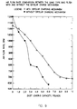
- Fig. 10 is a chart illustrating a DOP collection efficiency comparison between the same type bag filters with and without the bipolar charge mechanism.
DETAILED DESCRIPTION OF THE PREFERRED EMBODIMENTS
-
Fig. 1 is a schematic diagram of the elements used in the bipolar charged filter of the present invention.
-
A conventional prefilter 3 may be arranged upstream and used to intercept large size particles. It is typical in an air cleaning system to install a prefilter to prevent the main filtering system from being overloaded prematurely. Fine particles, e.g., less than 5 microns in diameter, usually pass through the crude prefilter and enter the ionizer 1.
-
The ionizer 1 includes two rows of ionizing wires 47, 48, one being connected to a positive output high voltage DC power supply 5 and the other to a negative output high voltage DC power supply 4, respectively. These two sets of ionizing wires 47, 48 are preferably not powered simultaneously. Instead, a repeated cycle time relay 6 is used to control the cycle time of both the positive and negative ionizations. Adjusting knobs 11 and 12 are used to set the cycle times for both the positive and negative power supplies. The cycles can be continued indefinitely until the input power to the relay 6 is cut off.
-
As an alternative embodiment, a single ionizer, or set of ionizing wires, may be used together with a high voltage relay. The relay will alternately connect the single set of ionizing wires to the positive high voltage source 5 and the negative high voltage source 4.
-
Another alternative embodiment uses a single ionizer, or set of ionizing wires, and a single high voltage power source. The high voltage power source can be configured to alternately emit a positive high voltage and a negative high voltage.
-
A pleated bag filter 2 is placed downstream of the ionizer 1 to collect the particles. It should be noted that any media filters, preferably those made of high dielectric strength material, can be used in this invention regardless the size, shape and configuration of the filter. For example, the filter 2 can be a panel filter or a cylindrical cartridge filter. The filter material can be polypropylene, polyethylene, or any other material with good dielectric strength.
-
The fibrous bag filter 2 initially may not carry any electronic charges in this system. However, as the power is turned on, either the negative power supply 4 or the positive power supply 5 is energized first.
-
For this description, it is assumed that the negative power supply 4 is energized first. Energization of the negative power supply 4 creates negative ions in high concentration (about 10 to 100 millions per cubic centimeter) in the ionizer 1. Airborne particles passing through the ionizer are thus charged negatively. These negatively charged particles 7 will be collected by the bag filter 2 by mechanical collection mechanisms such as inertia impaction, interception, diffusion as well as by the electrical image force.
-
The electric charges are sustained on the deposited particles due to the high electrical resistance of the fibers. The charges in turn charge the fibers negatively. This negative charging process continues until the time relay 6 kicks in the positive power supply 5 and shuts down the negative power supply 4. As soon as this power alternation happens, particles passing through the ionizer 1 are then charged positively. These positively charged particles 8 react to the negatively charged fiber surfaces of the bag filter 2 by the Coulomb force. This reaction enhances significantly the collection efficiency of the bag filter 2.
-
The collection efficiency of a 40% bag filter was increased to 99% by this effect in the test. The collection of the positively charged particles 8 on the negatively charged bag filter 2 tends to neutralize the net charge of the bag filter 2 to an extent. However, the two charge cycles can be set at different intervals. For example, the negative power cycle can be set for a period that is twice as long as the positive power cycle (or vice versa), so that the negative charges generated on the fiber surfaces are sufficiently more than the positive charges (or vice versa). In this situation, the bag filter 2 will consistently maintain a net negative (or positive) charge status throughout the operation.
-
Fig. 2 is a top view of a filtration system utilizing the bipolar charged filter of the present invention. It shows sequentially in the air flow direction (arrow A), the prefilter 3, the bipolar charge ionizer 1, the pleated bag filter 2, a motor 18, a blower 19, and an exhaust grill 20. These elements may be installed in a metal cabinet 13. A power supply and electrical control compartment 28 may be mounted behind an access door 52, which can be opened to service the prefilter 3, the ionizer 1, and the bag filter 2. Inside the compartment 28 are power supplies 27, power indicating lights 24 and 26, a time relay 23, a main switch 25, and other accessories necessary to provide a complete system. Latches 30 are used to lock the access door 52 to the cabinet. Another access door 21 is provided to service the blower section. The blower system shown is driven by belt 22. However, a direct drive type of blower also can be used. An electrical wiring box 17 is used to connect the system to a power source. The high voltage outputs are connected from the power supplies to the bipolar ionizer 1 through two high voltage contacts 29.
-
Fig. 3 is a front view of the same bipolar charged filter unit with the access doors and the power supply compartment removed, giving a clear view of the prefilter 3, the bipolar ionizer 1, the charged bag filter 2, the motor 18 and the blower in the cabinet. Both the motor 18 and the blower 19 are mounted to the cabinet by bolts and nuts 31, 32. Electrical wires 33 are to be connected to the power supply and electrical control compartment for proper control and operation.
-
Fig. 4 shows a top view of the bipolar ionizer. Four corner braces 35 are used to hold the structure of the ionizer 1. Ground plates 41 are riveted to the braces 35. High voltage insulators 36 are used to hold the ionizing wire supports 39 and 40. The insulators 36 are secured to the braces 35 by screws 38. There are two rows of ionizing wires 47, 48.
-
Fig. 5 is section on line AA of Fig. 4, showing one of the sets of ionizing wires 47, 48. The top and bottom ionizing wire supports 40, 46 and 39, 54 hold the ionizing wires 47, 48 in position.
-
The ionizing wires 47, 48 are preferably fine tungsten wires about 7 to 10 mil in diameter. They are cut to a specified length and coiled to give a spring effect. Crunching nuts 44 are put at the ends of the wires. One end of each of the ionizing wires 47, 48 is preferably placed into a slot made on the top support 40. The wire is then stretched to meet the respective slot on the bottom support 46. The spring effect of the coiled tungsten wire creates a tension that holds the wire in position, typically along a center line between two adjacent ground plates.
-
Alternatively, instead of ionizing wires 47, 48, other corona discharging configurations may be used. For example, corona discharging surfaces such as sharp needles or spikes formed on thin sheet metal may be used instead of, or in addition to, ionizing wires.
-
When high voltage is applied, the ionizing wires 47, 48 begin to discharge corona and charge the particles passing through the ionizer 1. The two sets of ionizing wires 47, 48 are separate and independent from each other. As described above, they are connected to two different power supplies, one positive 5 and the other negative 4 in output and powered in alternate timing with respect to one another to create the bipolar charge effect.
-
Fig. 6 is section on line BB of Fig 4. It shows one of the ground plates 41, the ionizing wires 47, 48, the corner braces 35, insulators 36 holding the ionizing wire supports 39, 40, 46, 54 and the screws 38 that hold the insulators 36 to the braces 35, and the ionizing wire supports 39, 40, 46, 54 to the insulators 36.
-
As shown in Fig. 5, the corner braces 35 are held at each end by end pieces 55. The end pieces 55 are fastened to the corner braces 35 by bolts 56, or other suitable means. The ground plates 41 are mounted to the corner braces 35 by plates 42.
-
Since the two sets of ionizing wires 47, 48 are independent from each other and connected to two different power supplies 4, 5, it is possible to use two separate ionizers to achieve the same purpose, such as shown in Fig. 7. Such arrangement should also be considered as part of this invention.
TEST RESULTS
-
The invention will be further illustrated by the following examples. DOP (dioctyl phthalate) droplets were generated by an atomizer and challenged the invention device. The collection efficiency was measured by a Quartz Crystal Microbalance (QCM) 10-Stage Cascade Impactor (California Measurements, Inc.).
-
A fibrous bag filter 18 "W x 18 "L x 12"D was placed in a test duct and its DOP collection efficiency was measured at an air flow rate of 1150 cfm. Upstream and downstream DOP concentrations were measured and the collection efficiency was 40%. Then the bipolar charge ionizer was installed in front of the bag filter. The time relay was set to give 60 seconds negative and 30 seconds positive power cycles and the power was turned on. The output voltage and current measured from the negative power supply cycle was -11.8 kv and -1.8 mA, and 12.2 kv and 1.9 mA from the positive power cycle, respectively. With the ionizer on, the DOP collection efficiency was increased to 99%. The bipolar charge effect showed a significant enhancement in the efficiency.
-
The effect of the bipolar charge on the loading capacity and pressure drop of the fibrous filter was then studied. A prototype bipolar charged filter system as that described in Fig. 2 was used in the study. Flour powders were fed into the system. The metal mesh prefilter was not able to capture the fine powders and practically all of the powders went into the ionizer and the bag filter.
-
Fig. 8 and Fig. 9 show the pressure drop curves and the air flow rate of two similar type bag filters, with and without activating the bipolar charge ionizer, respectively. As seen, the bipolar charged filter showed a smaller increase in pressure drop, more dust loading, and higher air flow rate. These distinct advantages are largely the result of electrical deposition.
-
More specifically, the electrical forces change the morphology of particle deposition. Instead of clogging the porosity of the fibrous filter, charged particles deposit on top of each other and develop a chain-like deposition pattern. These "dendrites" extend themselves away from the fiber surface, forming fine irregular shape cylinders, which become very effective collectors themselves and thus greatly enhance the particle collection efficiency of the filter. However, they cause little pressure drop increase because they do not clog the porosity among the fibers as much as when the ionizer is not used.
-
The effect of dust loading on the efficiency was also studied. The bipolar charged filter was placed in the test duct and flour powders fed from upstream at 1100 cfm one pound at a time. At the end of each pound dust loading, the DOP aerosols were generated and DOP collection efficiency of the bipolar charge filter measured. The same test was then repeated for another new bag filter of the same type without the bipolar charge ionizer. Fig. 10 shows the DOP collection efficiency comparison between two identical bag filters with and without the bipolar charge effect.
-
Table 1 lists the positive and negative cycle voltage, current, and DOP collection efficiencies up to 10 pounds of powder loading for the bipolar charge filter. Each DOP efficiency shown is an average of three consecutive samples. The cycle times were 30 seconds positive ionization and 60 seconds negative ionization, respectively. And Table 2 lists the test result for the bag filter without the bipolar charge ionizer. As can be seen, the efficiency was maintained very high throughout the load test for the bipolar charged filter. The pressure drop increased from 0.25 inches of water at the beginning of the loading test to 2.75 inches of water at the end of 10 pounds dust loading. In contrast, the DOP efficiency for the conventional bag filter without the bipolar charge effect was very low at the beginning (41%). Both the pressure drop and the efficiency increased as the filter was loaded, to 2.5 inches of water and 88%, respectively at the end of 3 pounds of powder loading. However, at the end of the 4th pound of loading, when the pressure drop measured 4.4 inches of water, the filter busted open and the test was terminated.
-
The ability to run with a very high initial efficiency, maintain at high efficiency and low pressure drop levels throughout a severe loading, is the unique advantage of this invention. As a further comparison to another air cleaning technique commonly used, the electrostatic precipitator (ESP), it is also more advantageous. Because for an ESP comparable in size, which handles about the same level of air flow rate, the ESP would have been loaded down by such a heavy loading. The corona current would have been diminished, and the cake formation in the collecting cell would have caused short-circuited or arc-over situations. And, the ESP would have to be shut down for cleaning and maintenance at about one or two pounds loading level.
-
Although the present invention has been described in connection with preferred embodiments thereof, it will be appreciated by those skilled in the art that additions, deletions, modifications, and substitutions not specifically described may be made without departing from the spirit and scope of the invention as defined in the appended claims.
TABLE 1 | total dust loading, lb | positive kv/ma | negative kv/ma | DOP efficiency percent |
| 0 | 12.2/1.87 | -11.8/-1.82 | 99.4% |
| 1 | 13.1/1.24 | -12.5/-1.51 | 88.9% |
| 2 | 13.1/1.15 | -12.9/-1.23 | 95.1% |
| 3 | 13.7/0.51 | -13.3/-0.82 | 95.3% |
| 4 | 13.9/0.28 | -13.5/-0.53 | 98.1% |
| 5 | 13.9/0.17 | -13.7/-0.40 | 96.6% |
| 6 | 14.0/0.14 | -13.8/-0.26 | 97.3% |
| 7 | 13.9/0.28 | -13.6/-0.45 | 91.2% |
| 8 | 13.9/0.23 | -13.7/-0.20 | 92.6% |
| 9 | 13.9/0.15 | -14.1/-0.07 | 94.6% |
| 10 | 13.9/0.14 | -14.2/-0.06 | 93.6% |
TABLE 2 | total dust loading, lb | positive kv/ma | negative kv/m | DOP efficiency percent |
| 0 | --- | --- | 41.1% |
| 1 | | | 45.1% |
| 2 | --- | --- | 79.2% |
| 3 | --- | --- | 88.0% |
| 4 | --- | --- | filter busted open |