EP0647918B1 - Carte portable multi-applications pour ordinateur personnel - Google Patents
Carte portable multi-applications pour ordinateur personnel Download PDFInfo
- Publication number
- EP0647918B1 EP0647918B1 EP94402200A EP94402200A EP0647918B1 EP 0647918 B1 EP0647918 B1 EP 0647918B1 EP 94402200 A EP94402200 A EP 94402200A EP 94402200 A EP94402200 A EP 94402200A EP 0647918 B1 EP0647918 B1 EP 0647918B1
- Authority
- EP
- European Patent Office
- Prior art keywords
- card
- connector
- tokens
- drawer
- token
- Prior art date
- Legal status (The legal status is an assumption and is not a legal conclusion. Google has not performed a legal analysis and makes no representation as to the accuracy of the status listed.)
- Expired - Lifetime
Links
Images

Classifications
-
- G—PHYSICS
- G06—COMPUTING; CALCULATING OR COUNTING
- G06K—GRAPHICAL DATA READING; PRESENTATION OF DATA; RECORD CARRIERS; HANDLING RECORD CARRIERS
- G06K19/00—Record carriers for use with machines and with at least a part designed to carry digital markings
- G06K19/06—Record carriers for use with machines and with at least a part designed to carry digital markings characterised by the kind of the digital marking, e.g. shape, nature, code
- G06K19/067—Record carriers with conductive marks, printed circuits or semiconductor circuit elements, e.g. credit or identity cards also with resonating or responding marks without active components
- G06K19/07—Record carriers with conductive marks, printed circuits or semiconductor circuit elements, e.g. credit or identity cards also with resonating or responding marks without active components with integrated circuit chips
- G06K19/072—Record carriers with conductive marks, printed circuits or semiconductor circuit elements, e.g. credit or identity cards also with resonating or responding marks without active components with integrated circuit chips the record carrier comprising a plurality of integrated circuit chips
-
- G—PHYSICS
- G06—COMPUTING; CALCULATING OR COUNTING
- G06K—GRAPHICAL DATA READING; PRESENTATION OF DATA; RECORD CARRIERS; HANDLING RECORD CARRIERS
- G06K19/00—Record carriers for use with machines and with at least a part designed to carry digital markings
- G06K19/06—Record carriers for use with machines and with at least a part designed to carry digital markings characterised by the kind of the digital marking, e.g. shape, nature, code
- G06K19/067—Record carriers with conductive marks, printed circuits or semiconductor circuit elements, e.g. credit or identity cards also with resonating or responding marks without active components
- G06K19/07—Record carriers with conductive marks, printed circuits or semiconductor circuit elements, e.g. credit or identity cards also with resonating or responding marks without active components with integrated circuit chips
- G06K19/077—Constructional details, e.g. mounting of circuits in the carrier
- G06K19/07737—Constructional details, e.g. mounting of circuits in the carrier the record carrier consisting of two or more mechanically separable parts
- G06K19/07741—Constructional details, e.g. mounting of circuits in the carrier the record carrier consisting of two or more mechanically separable parts comprising a first part operating as a regular record carrier and a second attachable part that changes the functional appearance of said record carrier, e.g. a contact-based smart card with an adapter part which, when attached to the contact card makes the contact card function as a non-contact card
-
- Y—GENERAL TAGGING OF NEW TECHNOLOGICAL DEVELOPMENTS; GENERAL TAGGING OF CROSS-SECTIONAL TECHNOLOGIES SPANNING OVER SEVERAL SECTIONS OF THE IPC; TECHNICAL SUBJECTS COVERED BY FORMER USPC CROSS-REFERENCE ART COLLECTIONS [XRACs] AND DIGESTS
- Y10—TECHNICAL SUBJECTS COVERED BY FORMER USPC
- Y10S—TECHNICAL SUBJECTS COVERED BY FORMER USPC CROSS-REFERENCE ART COLLECTIONS [XRACs] AND DIGESTS
- Y10S439/00—Electrical connectors
- Y10S439/946—Memory card cartridge
Definitions
- the invention relates to portable cards multi-applications intended to be inserted temporarily in a card reader doing part, in particular, of a microcomputer or computer personal, or PC (from English "personal computer").
- cards could replace in the near future floppy disks or other means of storing mass of magnetic type, as well as cards portable electronic cards such as smart cards.
- PCMCIA cards are not not sure.
- the information they contain is largely more accessible than the information that would in particular contain a smart card.
- the object of the present invention is to remedy these drawbacks of connection and complexity of manipulation, by proposing a PCMCIA card with a drawer capable of receiving such a token.
- such portable cards advantageously include a cover provided with receptacles intended to receive the tokens.
- the invention applies more particularly to PCMCIA format portable cards referenced 1 in the set of figures.
- PCMCIA format cards form a box 2 rectangular and rectangular whose dimensions are substantially equal to 5 x 8 cm for a thickness of the order of 3 mm.
- This case 2 can include, a microprocessor, and mass memory.
- a first 68-pin female 3 connector standardized is arranged on the periphery of the housing 2 on one of its short sides, in order to be plugged into a corresponding male connector of a computer staff.
- this side is a large side of the PCMCIA card.
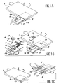
- This cavity 4 is intended to receive a drawer 5 shown in the open position in Figures 1A and 1B, and in the closed position in FIG. 1C.
- Drawer 5 is full except where cavity cutout or imprint referenced 6 in its together.
- This cutout 6 has a bottom 6a and substantially vertical edges 6b, having advantageously a slight draft.
- the bottom of the drawer 5 is in fact the bottom 6a of the cutout 6.
- Chips 7 to flush contacts or metallizations 15 can be deposited in the cavity cutter 6. These contacts are type of those typically found on maps mainly used for security access to premises, for banking transactions, or for services such as telephone communications.
- the chips 7 are themselves arranged each on an 8 token with a format smaller than the smart card format.
- the cutout 6 then advantageously takes the form tokens 8. These are, for example, part of a about 15 mm wide, 25 mm parallelepiped length, and 0.8 mm thick. One of the corners is cut to allow correct orientation of the token 8 or chip 7 relative to drawer 5.
- the scope of the invention is not limited not just portable cards with a single cavity 4 provided with a drawer 5, but it includes furthermore portable cards which have several cavities each with a drawer 5.
- the number of PCMCIA card pins may allow such a variant, given what the chips have usually 8 contacts at most. In this case, a possible microprocessor contained in the PCMCIA card can even multiplex between chips connected in the drawers.
- the portable cards of the invention have a second connector intended to make a connection between on the one hand, the eight contact pads flush 15 that conventionally comprises a chip and, on the other hand, the active elements of the PCMCIA card, to the first 68-pin connector.
- This second connector therefore has eight conductive wires connected either directly to the 68-pin connector, i.e. at a dialogue interface managed by the microprocessor of the card and in particular carrying out a conversion of protocol between signals sent or received by the chip and signals recognized by the personal computer.
- the second connector is arranged, as desired, in cavity 4, as shown on the right of FIG. 1B, or at the bottom of the drawer 5, in the cutout 6, as shown on the left side of this same figure.
- Token 8 is then oriented, in drawer 5, with metallizations 15 from chip 7 pointing upwards.
- the representation of second connector in FIG. 1B is then referenced 12.
- the connector 12 can in this case be fixed.
- the contact with chip 7 is formed as soon as the drawer 5, by a very precise adjustment, and with second connector contact pads with flexible parts such as, for example, contacts forming metal and elastic blades referenced 19 in FIG. 1C, in the right part, which shows a longitudinal section of the drawer 5 engaged in the card 1.
- the second connector can also be mobile. In this case, closing drawer 5 causes displacement contact pads from the second connector to the chip.
- the first case is that of a simple realization but chip 7 can be scratched by repeated contact with the connector blades 12.
- the second case does not include not this drawback but it is an achievement mechanically more difficult.
- the second realization is possible. In principle, it is that which is implemented in the connectors known smart cards of the so-called landing type.
- the second connector is disposed at the level of drawer 5, it is fixed on the bottom of the cutout 6. Its representation in FIG. 1B is then referenced 13.
- the token 8 must be removed with the chip connector 7 facing down.
- the second connector is then connected to flexible conductive wires 14, the length is sufficient to allow opening and closing of the drawer 5, without constraint.
- cavity 4 has a free space in the bottom to receive the strands of connection wires when the drawer is in the closed position. In practice, these wires exert an effort tending naturally to open the drawer. This solution is particularly interesting because chip 7 will not be crossed out by the connector 13, and the production of this connector is simple, relatively to what the achievement would be a movable connector.
- the side walls of the introductory slot of this player exercise advantageously a holding effort on a stopper 16 mounted at the end of this drawer, to keep it closed.
- the stopper 16 comprises a chamfer 17 to the front, in the direction of the introduction, to favor the engagement of the drawer 5. It is also possible to provide between the drawer 5 and the cavity 4, a slight friction or an elastic cleat to maintain the closed drawer. In this case, from below the drawer, there there is a tab to remove it.
- the drawer is preferably pierced, at its bottom, with a through hole 18 allowing the removal of the token 8.
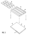
- the map 1 can receive a cover 9 provided with receptacles 10 intended to receive chips each supported by a token 8.
- This cover 9 is suitable for covering one of the two main faces of the PCMCIA card. he advantageously has a slightly longer length modest than this one, so as to leave the first connector 3 discovered.
- the cover 9 advantageously snaps onto the PCMCIA card thanks to to all the means that the man of the profession: small hooks, ledges, ..., and that not describe here.
- the cover 9 may include a slide in which we will introduce the PCMCIA card.
- this cover 9 can be fixed to a bottom constituting a box intended to receive the PCMCIA card.
- the receptacles shown in Figure 2 are cavities for example rubberized or provided with edges flexible, suitable for inserting chips 7 supported by their tokens 8, by manual snap-fastening.
- the cover 9 according to the invention has 9 tokens more.
- the bottom of each receptacle 10 has advantageously an orifice 11, for example circular, to enter a token.
- the receptacles 10 represented on the Figure 3 are formed by slides.
- the cover 9 comprises for example three slides intended for receive three tokens each 8.
- a user provided with a portable card according to the invention wishing to set up implements the determined application of a chip carried by a token 8 of the cover 9. This user must remove cover 9 from the PCMCIA card, select the appropriate token on cover 9, collect this token, open drawer 5, insert token 8 into this drawer, and close the drawer before engaging the card in the reader.
- the tokens 8 preferably include particular inscriptions or logos, which allows immediately select the token corresponding to the desired application.
- recovery of a token 8 is done either by dragging it into its receptacle (case of Figure 3), either by applying light finger pressure through hole 11 in order to release it (case of figure 2).
- connection between eight pads of the chip 7 forming the metallizations 15, and the active elements of the PCMCIA card towards the first connector 3, will be carried out respectively on the drawer 5 or in the cavity 4.
- the card can then be inserted in the reader and chip 7 will be in direct communication with the personal computer.
- the PCMCIA card can advantageously include a recognition system of the wearer such as a recognition system or by identification code.
- the card laptop could have tokens whose functions are different and for example a token telephone, a health token, a television token, a video game token, an identification token.
- Memory mass can be used for different applications, in combination with the associated tokens.
- memories associated with the card microprocessor PCMCIA then advantageously contain a directory personalized.
- the health token would make it possible for example payments for medical purposes, while the card PCMCIA would contain the medical file of its holder, emergency numbers.
- the television token would be used in particular in Pay-TV cases.
- Card memory PCMCIA would also contain programs television of the week, the preferences of user or subscriptions pending validation.
- the video games token would allow the purchase of games via a computer network, said games would then be immediately integrated into the mass memory of the PCMCIA card, possibly in compacted form.
- the identification token would allow access to information distributed over the network, or access physical to premises.
- the card PCMCIA would also contain an antenna for contactless access.
Description
- les figures 1A, 1B, 1C représentent respectivement l'ouverture du tiroir de la carte portable, le placement du jeton dans celui-ci, et sa fermeture ;
- la figure 2 illustre la superposition à une carte portable selon l'invention, d'un couvercle à réceptacles, et d'un ensemble de jetons ; et
- la figure 3 illustre la superposition à une carte portable selon l'invention, d'un couvercle à glissières, et d'un ensemble de jetons.
Claims (11)
- Carte portable multi-applications enfichable notamment dans un lecteur d'un ordinateur personnel, comportant un premier connecteur (3) destiné à une connexion avec ledit lecteur et disposé à la périphérie d'un boítier (2), de plus comportant d'une part, un tiroir mobile (5), disposé sur un chant de la carte (1), s'engageant dans une cavité (4) du boítier (2), comportant une découpe-cavité (6) destiné à recevoir une puce (7) supportée par un jeton (8) et, d'autre part, un second connecteur (12, 13) en relation électronique avec le premier connecteur (3), caractérisé en ce que la découpe-cavité (6) est munie d'un fond (6a) et en ce que le second connecteur (12,13) est fixé sur le fond du tiroir (5), ledit connecteur étant relié au premier connecteur (3) par l'intermédiaire de fils conducteurs (14) souples.
- Carte portable selon la revendication 1, caractérisée en ce que les dimensions du jeton (8) s'inscrivent dans un parallélépipède d'environ : 15 mm de largeur, 25 mm de longueur, et de 0,8 mm d'épaisseur.
- Carte portable selon l'une des revendications précédentes, caractérisée en ce qu'elle est basée sur le format PCMCIA.
- Carte portable selon l'une des revendications 1 à 3, caractérisée en ce que le tiroir (5) comporte un trou pour désengager le jeton (8) de la découpe-cavité (6).
- Carte portable selon l'une des revendications précédentes, caractérisée en ce qu'elle comporte en outre un couvercle (9) muni de réceptacles (10) pour les jetons (8).
- Carte portable selon la revendication 5, caractérisée en ce que les réceptacles (10) sont des glissières adaptées à la mise en place des jetons (8).
- Carte portable selon la revendication 5, caractérisée en ce que les réceptacles (10) sont des cavités munies de rebords souples adaptées à la mise en place des jetons (8) par encliquetage manuel et munis de trous pour permettre l'enlèvement des jetons (8).
- Carte portable selon l'une des revendications 5 à 7, caractérisée en ce que le couvercle (9) comporte des réceptacles (10) pour neuf jetons (8).
- Carte portable selon l'une des revendications précédentes, caractérisée en ce qu'un micro-processeur comporte un mécanisme de reconnaissance du porteur.
- Carte portable selon l'une des revendications précédentes, caractérisée en ce que la mémoire sécurisée du microprocesseur comporte les codes d'accès aux services des différentes puces (7) des jetons (8).
- Carte portable selon l'une des revendications précédentes, caractérisée en ce que la mémoire de masse peut être utilisée pour les différentes applications en combinaison avec les jetons (8) associés.
Applications Claiming Priority (3)
| Application Number | Priority Date | Filing Date | Title |
|---|---|---|---|
| FR9311925A FR2710996B1 (fr) | 1993-10-06 | 1993-10-06 | Carte portable multi-applications pour ordinateur personnel. |
| FR9311925 | 1993-10-06 | ||
| US08/321,679 US5563400A (en) | 1993-10-06 | 1994-10-12 | Multi-applications portable card for personal computer |
Publications (2)
| Publication Number | Publication Date |
|---|---|
| EP0647918A1 EP0647918A1 (fr) | 1995-04-12 |
| EP0647918B1 true EP0647918B1 (fr) | 1999-06-02 |
Family
ID=26230655
Family Applications (1)
| Application Number | Title | Priority Date | Filing Date |
|---|---|---|---|
| EP94402200A Expired - Lifetime EP0647918B1 (fr) | 1993-10-06 | 1994-10-03 | Carte portable multi-applications pour ordinateur personnel |
Country Status (7)
| Country | Link |
|---|---|
| US (1) | US5563400A (fr) |
| EP (1) | EP0647918B1 (fr) |
| JP (1) | JP3935975B2 (fr) |
| DE (1) | DE69418810T2 (fr) |
| ES (1) | ES2136178T3 (fr) |
| FR (1) | FR2710996B1 (fr) |
| SG (1) | SG48176A1 (fr) |
Families Citing this family (152)
| Publication number | Priority date | Publication date | Assignee | Title |
|---|---|---|---|---|
| JPH04329415A (ja) * | 1991-04-30 | 1992-11-18 | Fujitsu Ltd | カード型入出力インタフェース装置及びシステム |
| JPH08202835A (ja) * | 1995-01-24 | 1996-08-09 | Mitsubishi Electric Corp | Pcカード |
| KR960032232A (ko) * | 1995-02-25 | 1996-09-17 | 김광호 | 메모리 카드와 스마트카드 겸용 가능한 카드 리드/라이트 장치 |
| US5918163A (en) * | 1995-03-31 | 1999-06-29 | Compaq Computer Corporation | Electronic card assembly having a retractable antenna |
| FR2732790B1 (fr) * | 1995-04-05 | 1997-05-09 | Gemplus Card Int | Systeme de collecte d'informations pour lecteurs de cartes |
| JP3020020B2 (ja) * | 1995-05-18 | 2000-03-15 | モレックス インコーポレーテッド | カ−ド用コネクタ |
| JPH0950497A (ja) * | 1995-08-09 | 1997-02-18 | Hitachi Ltd | 電子マネー情報転送装置 |
| DE19530363A1 (de) * | 1995-08-18 | 1997-02-20 | Deutsche Telekom Ag | Modul |
| FR2738367B1 (fr) * | 1995-09-05 | 1997-10-17 | Scm Microsystems | Procede et appareil de telechargement rapide de fonctions dans une memoire volatile |
| WO1997010566A1 (fr) * | 1995-09-11 | 1997-03-20 | Elonex Plc | Carte a puce destinee a la communication avec un ordinateur personnel par l'intermediaire d'une interface pcmcia |
| US6076124A (en) | 1995-10-10 | 2000-06-13 | The Foxboro Company | Distributed control system including a compact easily-extensible and serviceable field controller |
| US6033257A (en) | 1995-11-20 | 2000-03-07 | The Foxboro Company | I/O connector module for a field controller in a distributed control system |
| FR2747847B1 (fr) * | 1996-04-18 | 1998-07-03 | Itt Composants Instr | Boitier de raccordement electronique, a un ordinateur individuel, equipe d'un connecteur pour une carte a puce |
| US5752857A (en) * | 1996-05-24 | 1998-05-19 | Itt Corporation | Smart card computer adaptor |
| JPH09315061A (ja) * | 1996-06-03 | 1997-12-09 | Minolta Co Ltd | Icカードおよびicカード装着装置 |
| DE19629351C2 (de) * | 1996-07-20 | 2002-10-24 | Wolfgang Neifer | Mobiles Chipkarten-Lesemodul |
| NL1003802C1 (nl) | 1996-07-24 | 1998-01-28 | Chiptec International Ltd | Identiteitsbewijs en identificatiesysteem bestemd voor toepassing daarmee. |
| EP0825506B1 (fr) | 1996-08-20 | 2013-03-06 | Invensys Systems, Inc. | Méthodes et appareil de commande à distance de processus |
| EP0833268A3 (fr) * | 1996-09-20 | 1999-01-20 | Siemens Aktiengesellschaft | Dispositif de lecture de carte |
| EP0849695A3 (fr) * | 1996-12-20 | 2000-09-06 | Tyco Electronics Logistics AG | Partie d'un porteur de carte |
| US7787647B2 (en) | 1997-01-13 | 2010-08-31 | Micro Ear Technology, Inc. | Portable system for programming hearing aids |
| US5954808A (en) * | 1997-09-17 | 1999-09-21 | Micron Electronics, Inc. | Method for configuring a computer-based system with a configuration card |
| US5991875A (en) * | 1997-09-17 | 1999-11-23 | Micron Electronics, Inc. | System configuration card |
| FR2771199B1 (fr) * | 1997-11-20 | 2002-11-15 | Sagem | Carte portable et systeme d'exploitation d'une telle carte |
| US6366863B1 (en) * | 1998-01-09 | 2002-04-02 | Micro Ear Technology Inc. | Portable hearing-related analysis system |
| US6015092A (en) * | 1998-02-05 | 2000-01-18 | Postlewaite; William M. | Smart card reader having angled smart card holder |
| US6173405B1 (en) | 1998-05-29 | 2001-01-09 | 3Com Corporation | Secure communications card modem and method of using same |
| JP2000207470A (ja) * | 1998-08-26 | 2000-07-28 | Hitachi Ltd | Icカ―ド、端末、サ―バ |
| US6460772B1 (en) * | 1998-09-01 | 2002-10-08 | Intertex Data Ab | PCMCIA smart card reader |
| EP1131759A2 (fr) | 1998-11-13 | 2001-09-12 | The Chase Manhattan Bank | Systeme et procede de traitement multidevises et multibanques via un reseau non protege |
| US6705529B1 (en) * | 1998-11-26 | 2004-03-16 | Nokia Mobile Phones, Ltd. | Data card holder and reader therefor |
| EP1188135A2 (fr) | 1998-12-23 | 2002-03-20 | The Chase Manhattan Bank | Systeme et procede d'integration d'operations commerciales comprenant la generation, le traitement et le suivi de documents commerciaux et documents concernes |
| JP2000357210A (ja) * | 1999-05-03 | 2000-12-26 | Amphenol Tuchel Electronics Gmbh | 接触装置 |
| US7068832B1 (en) | 1999-05-11 | 2006-06-27 | The Chase Manhattan Bank | Lockbox imaging system |
| US6353870B1 (en) * | 1999-05-11 | 2002-03-05 | Socket Communications Inc. | Closed case removable expansion card having interconnect and adapter circuitry for both I/O and removable memory |
| US6599147B1 (en) | 1999-05-11 | 2003-07-29 | Socket Communications, Inc. | High-density removable expansion module having I/O and second-level-removable expansion memory |
| WO2000070417A1 (fr) | 1999-05-17 | 2000-11-23 | The Foxboro Company | Systeme de configuration de commande de processus via des objets parametres |
| US7089530B1 (en) | 1999-05-17 | 2006-08-08 | Invensys Systems, Inc. | Process control configuration system with connection validation and configuration |
| DE19925146C2 (de) * | 1999-06-02 | 2003-01-09 | Itt Mfg Enterprises Inc | Steckkarte für elektronische Geräte |
| US6788980B1 (en) | 1999-06-11 | 2004-09-07 | Invensys Systems, Inc. | Methods and apparatus for control using control devices that provide a virtual machine environment and that communicate via an IP network |
| FR2795194B1 (fr) * | 1999-06-15 | 2002-08-23 | Gemplus Card Int | Extension pour module electronique de type pcmcia |
| US6315205B1 (en) | 1999-07-06 | 2001-11-13 | Itt Manufacturing Enterprises, Inc. | Adaptor for smart card |
| US6259409B1 (en) * | 1999-07-22 | 2001-07-10 | 3Com Corporation | Retractable sliding antenna assembly for wireless communication |
| EP1073006A1 (fr) | 1999-07-26 | 2001-01-31 | Molex Incorporated | Ejecteur de carte à puce |
| US6213403B1 (en) | 1999-09-10 | 2001-04-10 | Itt Manufacturing Enterprises, Inc. | IC card with fingerprint sensor |
| US7487908B1 (en) * | 1999-10-23 | 2009-02-10 | Ultracard, Inc. | Article having an embedded accessible storage member, apparatus and method for using same |
| US8397998B1 (en) | 1999-10-23 | 2013-03-19 | Ultracard, Inc. | Data storage device, apparatus and method for using same |
| US7805365B1 (en) | 1999-10-25 | 2010-09-28 | Jpmorgan Chase Bank, N.A. | Automated statement presentation, adjustment and payment system and method therefor |
| FR2800923A1 (fr) * | 1999-11-08 | 2001-05-11 | Framatome Connectors Int | Lecteur de carte a micro-circuit |
| GB2357189B (en) * | 1999-11-15 | 2001-11-07 | Psion Connect Ltd | Removable wireless device |
| JP3601686B2 (ja) * | 1999-12-17 | 2004-12-15 | 日本電気株式会社 | ディスクドライブシステム、ディスクドライブ及びメディアカートリッジ |
| EP1252799B2 (fr) | 2000-01-20 | 2022-11-02 | Starkey Laboratories, Inc. | Procédé et appareil pour l'adaptation des prothèses auditives |
| JP4339477B2 (ja) * | 2000-01-24 | 2009-10-07 | 日本圧着端子製造株式会社 | カード接続用アダプタ |
| US7822656B2 (en) | 2000-02-15 | 2010-10-26 | Jpmorgan Chase Bank, N.A. | International banking system and method |
| US8768836B1 (en) | 2000-02-18 | 2014-07-01 | Jpmorgan Chase Bank, N.A. | System and method for electronic deposit of a financial instrument by banking customers from remote locations by use of a digital image |
| JP2002008778A (ja) | 2000-04-20 | 2002-01-11 | Kel Corp | カードコネクタ |
| US7584125B2 (en) | 2000-06-26 | 2009-09-01 | Jpmorgan Chase Bank, N.A. | Electronic check presentment system and method having an item sequence capability |
| US8468071B2 (en) | 2000-08-01 | 2013-06-18 | Jpmorgan Chase Bank, N.A. | Processing transactions using a register portion to track transactions |
| WO2002015098A2 (fr) | 2000-08-11 | 2002-02-21 | Loy John J | Appareil et methode de traitement de comptes clients |
| US7206768B1 (en) | 2000-08-14 | 2007-04-17 | Jpmorgan Chase Bank, N.A. | Electronic multiparty accounts receivable and accounts payable system |
| US7107378B1 (en) | 2000-09-01 | 2006-09-12 | Sandisk Corporation | Cooperative interconnection and operation of a non-volatile memory card and an input-output card |
| AT501651B1 (de) * | 2000-09-27 | 2007-02-15 | Omnikey Gmbh | Elektronisches modul mit einem steckverbinder zu einer übergeordneten recheneinheit |
| US7587363B2 (en) | 2000-11-06 | 2009-09-08 | Jpmorgan Chase Bank, N.A. | System and method for optimized funding of electronic transactions |
| WO2002037386A1 (fr) | 2000-11-06 | 2002-05-10 | First Usa Bank, N.A. | Systeme et procede de financement selectif de transactions electroniques |
| JP2002189992A (ja) * | 2000-12-20 | 2002-07-05 | Sony Corp | メモリカードドライブと携帯型メモリカードドライブ |
| US8805739B2 (en) | 2001-01-30 | 2014-08-12 | Jpmorgan Chase Bank, National Association | System and method for electronic bill pay and presentment |
| US6494366B2 (en) * | 2001-01-31 | 2002-12-17 | Hewlett-Packard Company | Removable merchant card drawer and method for using same |
| US7401048B2 (en) | 2001-06-01 | 2008-07-15 | Jpmorgan Chase Bank, N.A. | System and method for trade settlement tracking and relative ranking |
| GB0123677D0 (en) * | 2001-10-03 | 2001-11-21 | Ibm | Device connecting card |
| US7822684B2 (en) | 2001-10-05 | 2010-10-26 | Jpmorgan Chase Bank, N.A. | Personalized bank teller machine |
| US7243853B1 (en) * | 2001-12-04 | 2007-07-17 | Visa U.S.A. Inc. | Method and system for facilitating memory and application management on a secured token |
| TW507950U (en) * | 2001-12-26 | 2002-10-21 | Hon Hai Prec Ind Co Ltd | Electronic card connector |
| US7440774B2 (en) | 2002-04-08 | 2008-10-21 | Socket Mobile, Inc. | Wireless enabled memory module |
| CN1472698A (zh) * | 2002-05-20 | 2004-02-04 | 奎德诺威申有限公司 | 非接触交易卡及其适配器 |
| US7689482B2 (en) | 2002-05-24 | 2010-03-30 | Jp Morgan Chase Bank, N.A. | System and method for payer (buyer) defined electronic invoice exchange |
| US6808396B2 (en) * | 2002-05-24 | 2004-10-26 | Symbol Technologies, Inc. | Connection of a user identity module to a compact card case |
| US7519560B2 (en) | 2002-05-24 | 2009-04-14 | Jpmorgan Chase Bank, N.A. | System and method for electronic authorization of batch checks |
| US7437327B2 (en) | 2002-05-24 | 2008-10-14 | Jp Morgan Chase Bank | Method and system for buyer centric dispute resolution in electronic payment system |
| US20030220863A1 (en) | 2002-05-24 | 2003-11-27 | Don Holm | System and method for varying electronic settlements between buyers and suppliers with dynamic discount terms |
| US20040139021A1 (en) | 2002-10-07 | 2004-07-15 | Visa International Service Association | Method and system for facilitating data access and management on a secure token |
| US7367503B2 (en) * | 2002-11-13 | 2008-05-06 | Sandisk Corporation | Universal non-volatile memory card used with various different standard cards containing a memory controller |
| US20050055479A1 (en) * | 2002-11-21 | 2005-03-10 | Aviad Zer | Multi-module circuit card with inter-module direct memory access |
| US8037229B2 (en) * | 2002-11-21 | 2011-10-11 | Sandisk Technologies Inc. | Combination non-volatile memory and input-output card with direct memory access |
| US7769650B2 (en) | 2002-12-03 | 2010-08-03 | Jp Morgan Chase Bank | Network-based sub-allocation systems and methods for swaps |
| US10311412B1 (en) | 2003-03-28 | 2019-06-04 | Jpmorgan Chase Bank, N.A. | Method and system for providing bundled electronic payment and remittance advice |
| US8630947B1 (en) | 2003-04-04 | 2014-01-14 | Jpmorgan Chase Bank, N.A. | Method and system for providing electronic bill payment and presentment |
| US7305535B2 (en) * | 2003-04-17 | 2007-12-04 | Sandisk Corporation | Memory cards including a standard security function |
| DE60331596D1 (de) * | 2003-04-23 | 2010-04-15 | Panasonic Corp | Halbleiteraufzeichnungsvorrichtung |
| DE10324996A1 (de) * | 2003-06-03 | 2005-02-17 | Giesecke & Devrient Gmbh | Chipkarte mit wenigstens einer Applikation |
| US7613656B2 (en) | 2003-08-11 | 2009-11-03 | Jp Morgan Chase Bank | Coupon payment system |
| FR2858866B1 (fr) * | 2003-08-14 | 2005-12-02 | Datacard Inc | Element d'adaptation pour supports electroniques programmables et utilisation dans une machine de personnalisation universelle |
| US7792717B1 (en) | 2003-10-31 | 2010-09-07 | Jpmorgan Chase Bank, N.A. | Waterfall prioritized payment processing |
| US7702577B1 (en) | 2003-11-06 | 2010-04-20 | Jp Morgan Chase Bank, N.A. | System and method for conversion of initial transaction to final transaction |
| FR2862409B1 (fr) * | 2003-11-17 | 2006-04-14 | Datacard Inc | Element d'adaptation pour supports electroniques programmables |
| US7209995B2 (en) * | 2003-12-09 | 2007-04-24 | Sandisk Corporation | Efficient connection between modules of removable electronic circuit cards |
| US7814003B2 (en) | 2003-12-15 | 2010-10-12 | Jp Morgan Chase | Billing workflow system for crediting charges to entities creating derivatives exposure |
| ATE453168T1 (de) * | 2004-01-13 | 2010-01-15 | Seiko Instr Inc | System mit elektronischer vorrichtung von kartentyp und elektronische vorrichtung von kartentyp |
| US7380707B1 (en) | 2004-02-25 | 2008-06-03 | Jpmorgan Chase Bank, N.A. | Method and system for credit card reimbursements for health care transactions |
| US7761923B2 (en) | 2004-03-01 | 2010-07-20 | Invensys Systems, Inc. | Process control methods and apparatus for intrusion detection, protection and network hardening |
| US7240144B2 (en) * | 2004-04-02 | 2007-07-03 | Arm Limited | Arbitration of data transfer requests |
| US8554673B2 (en) | 2004-06-17 | 2013-10-08 | Jpmorgan Chase Bank, N.A. | Methods and systems for discounts management |
| US8121944B2 (en) | 2004-06-24 | 2012-02-21 | Jpmorgan Chase Bank, N.A. | Method and system for facilitating network transaction processing |
| US8290862B2 (en) | 2004-07-23 | 2012-10-16 | Jpmorgan Chase Bank, N.A. | Method and system for expediting payment delivery |
| US8290863B2 (en) | 2004-07-23 | 2012-10-16 | Jpmorgan Chase Bank, N.A. | Method and system for expediting payment delivery |
| FR2875625B1 (fr) * | 2004-09-20 | 2006-12-08 | Gemplus Sa | Support adaptateur de carte a puce deverrouillable et procede de fabrication du support |
| WO2006093294A1 (fr) * | 2005-03-04 | 2006-09-08 | Nec Corporation | Connecteur de carte et appareil electronique |
| US7822682B2 (en) | 2005-06-08 | 2010-10-26 | Jpmorgan Chase Bank, N.A. | System and method for enhancing supply chain transactions |
| US7676409B1 (en) | 2005-06-20 | 2010-03-09 | Jpmorgan Chase Bank, N.A. | Method and system for emulating a private label over an open network |
| US8301529B1 (en) | 2005-11-02 | 2012-10-30 | Jpmorgan Chase Bank, N.A. | Method and system for implementing effective governance of transactions between trading partners |
| US7860857B2 (en) | 2006-03-30 | 2010-12-28 | Invensys Systems, Inc. | Digital data processing apparatus and methods for improving plant performance |
| US20070240178A1 (en) * | 2006-04-07 | 2007-10-11 | Kleker Richard G | Apparatus and method for storing digital data |
| US7734545B1 (en) | 2006-06-14 | 2010-06-08 | Jpmorgan Chase Bank, N.A. | Method and system for processing recurring payments |
| CA2601662A1 (fr) | 2006-09-18 | 2008-03-18 | Matthias Mullenborn | Interface sans fil pour programmer des dispositifs d'aide auditive |
| US7916925B2 (en) | 2007-02-09 | 2011-03-29 | Jpmorgan Chase Bank, N.A. | System and method for generating magnetic ink character recognition (MICR) testing documents |
| US8762640B2 (en) * | 2007-06-27 | 2014-06-24 | Sandisk Il Ltd. | Method for operating a memory interface with SIM functions |
| US8762270B1 (en) | 2007-08-10 | 2014-06-24 | Jpmorgan Chase Bank, N.A. | System and method for providing supplemental payment or transaction information |
| US7841538B2 (en) * | 2007-10-31 | 2010-11-30 | Target Brands, Inc. | Transaction product with memory |
| US8788281B1 (en) | 2007-12-03 | 2014-07-22 | Jp Morgan Chase Bank, N.A. | System and method for processing qualified healthcare account related financial transactions |
| US7766244B1 (en) | 2007-12-31 | 2010-08-03 | Jpmorgan Chase Bank, N.A. | System and method for processing transactions using a multi-account transactions device |
| US8622308B1 (en) | 2007-12-31 | 2014-01-07 | Jpmorgan Chase Bank, N.A. | System and method for processing transactions using a multi-account transactions device |
| EP2304536A4 (fr) | 2008-06-20 | 2012-08-15 | Invensys Sys Inc | Systèmes et procédés pour une interaction immersive avec des équipements réels et/ou simulés pour un contrôle de processus, environnemental et industriel |
| US8112355B1 (en) | 2008-09-05 | 2012-02-07 | Jpmorgan Chase Bank, N.A. | Method and system for buyer centric dispute resolution in electronic payment system |
| US7996613B2 (en) * | 2008-09-10 | 2011-08-09 | Portwell Inc. | Electronic device using memory to expand storage capacity |
| US7713091B2 (en) * | 2008-09-12 | 2010-05-11 | Getac Technology Corp. | Adaptor device for connecting and accessing data card and computer device incorporating the adaptor device |
| US20100078485A1 (en) * | 2008-09-29 | 2010-04-01 | Dynacard Co., Ltd. | Subscriber identity module card |
| US8391584B2 (en) | 2008-10-20 | 2013-03-05 | Jpmorgan Chase Bank, N.A. | Method and system for duplicate check detection |
| US9092447B1 (en) | 2008-10-20 | 2015-07-28 | Jpmorgan Chase Bank, N.A. | Method and system for duplicate detection |
| US8463964B2 (en) | 2009-05-29 | 2013-06-11 | Invensys Systems, Inc. | Methods and apparatus for control configuration with enhanced change-tracking |
| US8127060B2 (en) | 2009-05-29 | 2012-02-28 | Invensys Systems, Inc | Methods and apparatus for control configuration with control objects that are fieldbus protocol-aware |
| CN102111464A (zh) * | 2009-12-28 | 2011-06-29 | 鸿富锦精密工业(深圳)有限公司 | 卡片组件及具有该卡片组件的电子设备 |
| US8447641B1 (en) | 2010-03-29 | 2013-05-21 | Jpmorgan Chase Bank, N.A. | System and method for automatically enrolling buyers into a network |
| US8589288B1 (en) | 2010-10-01 | 2013-11-19 | Jpmorgan Chase Bank, N.A. | System and method for electronic remittance of funds |
| US8543504B1 (en) | 2011-03-30 | 2013-09-24 | Jpmorgan Chase Bank, N.A. | Systems and methods for automated invoice entry |
| US8543503B1 (en) | 2011-03-30 | 2013-09-24 | Jpmorgan Chase Bank, N.A. | Systems and methods for automated invoice entry |
| USD702692S1 (en) * | 2011-11-23 | 2014-04-15 | Digital Hard Copy | Card for holding a digital storage medium |
| USD702693S1 (en) * | 2011-11-23 | 2014-04-15 | Digital Hard Copy | Digital storage medium card |
| US8654535B2 (en) * | 2012-03-08 | 2014-02-18 | Proconn Technology Co., Ltd. | Card holder |
| CN103377680B (zh) * | 2012-04-24 | 2016-03-09 | 神讯电脑(昆山)有限公司 | 光盘读取装置 |
| USD678653S1 (en) | 2012-07-19 | 2013-03-19 | Jpmorgan Chase Bank, N.A. | Drive-up financial transaction machine |
| CN103700380A (zh) * | 2012-09-28 | 2014-04-02 | 鸿富锦精密工业(深圳)有限公司 | 具有存储设备的光驱 |
| USD707682S1 (en) * | 2012-12-05 | 2014-06-24 | Logomotion, S.R.O. | Memory card |
| US8814582B2 (en) * | 2013-01-18 | 2014-08-26 | Proconn Technology Co., Ltd. | Card connector |
| USD758372S1 (en) | 2013-03-13 | 2016-06-07 | Nagrastar Llc | Smart card interface |
| USD759022S1 (en) * | 2013-03-13 | 2016-06-14 | Nagrastar Llc | Smart card interface |
| USD729808S1 (en) | 2013-03-13 | 2015-05-19 | Nagrastar Llc | Smart card interface |
| US9647997B2 (en) | 2013-03-13 | 2017-05-09 | Nagrastar, Llc | USB interface for performing transport I/O |
| US9888283B2 (en) | 2013-03-13 | 2018-02-06 | Nagrastar Llc | Systems and methods for performing transport I/O |
| USD690074S1 (en) | 2013-03-13 | 2013-09-17 | Jpmorgan Chase Bank, N.A. | Financial transaction machine |
| US9058626B1 (en) | 2013-11-13 | 2015-06-16 | Jpmorgan Chase Bank, N.A. | System and method for financial services device usage |
| USD780763S1 (en) | 2015-03-20 | 2017-03-07 | Nagrastar Llc | Smart card interface |
| USD864968S1 (en) | 2015-04-30 | 2019-10-29 | Echostar Technologies L.L.C. | Smart card interface |
| JP6613130B2 (ja) * | 2015-12-22 | 2019-11-27 | モレックス エルエルシー | カード保持部材及びカード用コネクタセット |
Family Cites Families (13)
| Publication number | Priority date | Publication date | Assignee | Title |
|---|---|---|---|---|
| JPS6228892A (ja) * | 1985-07-31 | 1987-02-06 | Toshiba Corp | Icカ−ドホルダ |
| FR2632752B1 (fr) * | 1988-06-08 | 1991-12-06 | Parienti Raoul | Carte a puce bi-module memoire |
| US5296692A (en) * | 1988-10-24 | 1994-03-22 | Sharp Kabushiki Kaisha | IC card adapter for use in memory card slot with or without superimposed memory card |
| FR2653248B1 (fr) * | 1989-10-13 | 1991-12-20 | Gemolus Card International | Systeme de paiement ou de transfert d'information par carte a memoire electronique porte monnaie. |
| JPH03141486A (ja) * | 1989-10-27 | 1991-06-17 | Hitachi Ltd | メモリカード受コネクタ |
| JPH03194680A (ja) * | 1989-12-22 | 1991-08-26 | Omron Corp | メモリカード用アダプタ |
| FR2657445B1 (fr) * | 1990-01-25 | 1992-04-10 | Gemplus Card Int | Procede de chargement de programmes d'application dans un lecteur de carte a memoire a microprocesseur et systeme destine a sa mise en óoeuvre. |
| FR2657706B1 (fr) * | 1990-01-30 | 1992-11-27 | Gemplus Card Internal Sa | Procede et dispositif de gestion de transactions utilisant des cartes a microcircuit. |
| US5049728A (en) * | 1990-04-04 | 1991-09-17 | Rovin George H | IC card system with removable IC modules |
| US5430617A (en) * | 1991-09-30 | 1995-07-04 | Hsu; Winston | Modular electronic packaging for internal I/O modules |
| JP3173171B2 (ja) * | 1991-12-19 | 2001-06-04 | カシオ計算機株式会社 | 情報転送システム |
| US5334030A (en) * | 1992-06-01 | 1994-08-02 | National Semiconductor Corporation | PCMCIA bus extender card for PCMCIA system development |
| US5436621A (en) * | 1993-07-02 | 1995-07-25 | Motorola, Inc. | Messaging peripheral with secure message data function |
-
1993
- 1993-10-06 FR FR9311925A patent/FR2710996B1/fr not_active Expired - Lifetime
-
1994
- 1994-10-03 SG SG1996007626A patent/SG48176A1/en unknown
- 1994-10-03 DE DE69418810T patent/DE69418810T2/de not_active Expired - Lifetime
- 1994-10-03 ES ES94402200T patent/ES2136178T3/es not_active Expired - Lifetime
- 1994-10-03 EP EP94402200A patent/EP0647918B1/fr not_active Expired - Lifetime
- 1994-10-06 JP JP26838594A patent/JP3935975B2/ja not_active Expired - Fee Related
- 1994-10-12 US US08/321,679 patent/US5563400A/en not_active Expired - Lifetime
Also Published As
| Publication number | Publication date |
|---|---|
| SG48176A1 (en) | 1998-04-17 |
| JPH07239924A (ja) | 1995-09-12 |
| US5563400A (en) | 1996-10-08 |
| ES2136178T3 (es) | 1999-11-16 |
| JP3935975B2 (ja) | 2007-06-27 |
| FR2710996B1 (fr) | 1995-12-01 |
| DE69418810D1 (de) | 1999-07-08 |
| FR2710996A1 (fr) | 1995-04-14 |
| EP0647918A1 (fr) | 1995-04-12 |
| DE69418810T2 (de) | 1999-10-21 |
Similar Documents
| Publication | Publication Date | Title |
|---|---|---|
| EP0647918B1 (fr) | Carte portable multi-applications pour ordinateur personnel | |
| EP0696010B2 (fr) | Interface portable pour carte à puce électronique | |
| EP0552078B1 (fr) | Carte enfichable pour microordinateur formant lecteur de carte à contacts affleurants | |
| CA1147413A (fr) | Connecteur pour objets portatifs | |
| WO2003027946A1 (fr) | Cle electronique destinee a etre connectee a un port d'un dispositif de telecommunication | |
| FR2903514A1 (fr) | Boitier pour clef electronique et systeme comportant un tel boitier | |
| EP1181663B1 (fr) | Lecteur portatif de modules au format mini-carte pour une connexion a un port d'un ordinateur personnel | |
| EP0338900A1 (fr) | Dispositif de mise en contact électrique de conducteurs répartis sur deux éléments et notamment entre ceux d'une carte à mémoire et ceux de son lecteur | |
| EP0263746B1 (fr) | Système à lecture de cartes d'identification à contacts électriques | |
| EP0980561B2 (fr) | Carte amovible a connecteur enfichable, formant lecteur de carte a puce pour micro-ordinateur | |
| EP2239691B1 (fr) | Ensemble à clé mémoire comprenant une carte à microcircuit | |
| EP2926292B1 (fr) | Trappe pour terminal | |
| FR2696863A1 (fr) | Cartouche intermédiaire polyvalente. | |
| EP0867011B1 (fr) | Lecteur portable de carte a puce apte a fonctionner meme range | |
| FR2722589A1 (fr) | Interface portable pour carte a puce electronique | |
| FR2941807A1 (fr) | Dispositif electronique, de type a connecteur usb, personnalisable. | |
| EP1374163B1 (fr) | Carrousel a puces electroniques | |
| EP1252845A1 (fr) | Module de récupérateur de supports de données numériques à puce sans contact | |
| WO2000019368A1 (fr) | Carte a module secable | |
| FR2763718A1 (fr) | Connecteur avec insertion directe ou indirecte d'une carte a puce en son sein | |
| EP1053529B1 (fr) | Lecteur de cartes a memoire electronique protege contre le vandalisme | |
| FR2861483A1 (fr) | Procede de fabrication d'une cle electronique a connecteur usb et cle electronique obtenue | |
| EP1556833B2 (fr) | Jeu de cartes à microcircuit prédécoupées dans un même support plastique et comportant des fonctions complémentaires | |
| WO2001031574A1 (fr) | Support de donnees numeriques compressees, dispositif lecteur et/ou enregistreur dudit support | |
| WO2010031917A1 (fr) | Objet portable pourvu d'une personnalisation graphique verrouillée à l'intérieur de son boîtier |
Legal Events
| Date | Code | Title | Description |
|---|---|---|---|
| PUAI | Public reference made under article 153(3) epc to a published international application that has entered the european phase |
Free format text: ORIGINAL CODE: 0009012 |
|
| AK | Designated contracting states |
Kind code of ref document: A1 Designated state(s): DE ES GB IT |
|
| 17P | Request for examination filed |
Effective date: 19950314 |
|
| 17Q | First examination report despatched |
Effective date: 19970425 |
|
| GRAG | Despatch of communication of intention to grant |
Free format text: ORIGINAL CODE: EPIDOS AGRA |
|
| GRAG | Despatch of communication of intention to grant |
Free format text: ORIGINAL CODE: EPIDOS AGRA |
|
| GRAH | Despatch of communication of intention to grant a patent |
Free format text: ORIGINAL CODE: EPIDOS IGRA |
|
| GRAH | Despatch of communication of intention to grant a patent |
Free format text: ORIGINAL CODE: EPIDOS IGRA |
|
| GRAA | (expected) grant |
Free format text: ORIGINAL CODE: 0009210 |
|
| AK | Designated contracting states |
Kind code of ref document: B1 Designated state(s): DE ES GB IT |
|
| REF | Corresponds to: |
Ref document number: 69418810 Country of ref document: DE Date of ref document: 19990708 |
|
| GBT | Gb: translation of ep patent filed (gb section 77(6)(a)/1977) |
Effective date: 19990730 |
|
| ITF | It: translation for a ep patent filed |
Owner name: PORTA CHECCACCI & ASSOCIATI S.P.A. |
|
| REG | Reference to a national code |
Ref country code: ES Ref legal event code: FG2A Ref document number: 2136178 Country of ref document: ES Kind code of ref document: T3 |
|
| PLBE | No opposition filed within time limit |
Free format text: ORIGINAL CODE: 0009261 |
|
| STAA | Information on the status of an ep patent application or granted ep patent |
Free format text: STATUS: NO OPPOSITION FILED WITHIN TIME LIMIT |
|
| 26N | No opposition filed | ||
| REG | Reference to a national code |
Ref country code: GB Ref legal event code: IF02 |
|
| PGFP | Annual fee paid to national office [announced via postgrant information from national office to epo] |
Ref country code: GB Payment date: 20120924 Year of fee payment: 19 |
|
| PGFP | Annual fee paid to national office [announced via postgrant information from national office to epo] |
Ref country code: IT Payment date: 20120921 Year of fee payment: 19 |
|
| PGFP | Annual fee paid to national office [announced via postgrant information from national office to epo] |
Ref country code: DE Payment date: 20120924 Year of fee payment: 19 |
|
| PGFP | Annual fee paid to national office [announced via postgrant information from national office to epo] |
Ref country code: ES Payment date: 20121005 Year of fee payment: 19 |
|
| GBPC | Gb: european patent ceased through non-payment of renewal fee |
Effective date: 20131003 |
|
| PG25 | Lapsed in a contracting state [announced via postgrant information from national office to epo] |
Ref country code: GB Free format text: LAPSE BECAUSE OF NON-PAYMENT OF DUE FEES Effective date: 20131003 |
|
| REG | Reference to a national code |
Ref country code: DE Ref legal event code: R119 Ref document number: 69418810 Country of ref document: DE Effective date: 20140501 |
|
| PG25 | Lapsed in a contracting state [announced via postgrant information from national office to epo] |
Ref country code: DE Free format text: LAPSE BECAUSE OF NON-PAYMENT OF DUE FEES Effective date: 20140501 Ref country code: IT Free format text: LAPSE BECAUSE OF NON-PAYMENT OF DUE FEES Effective date: 20131003 |
|
| REG | Reference to a national code |
Ref country code: ES Ref legal event code: FD2A Effective date: 20141107 |
|
| PG25 | Lapsed in a contracting state [announced via postgrant information from national office to epo] |
Ref country code: ES Free format text: LAPSE BECAUSE OF NON-PAYMENT OF DUE FEES Effective date: 20131004 |