EP0650036A2 - Ultrasonic pulsed Doppler flow measurement system with two dimensional autocorrelation processing - Google Patents
Ultrasonic pulsed Doppler flow measurement system with two dimensional autocorrelation processing Download PDFInfo
- Publication number
- EP0650036A2 EP0650036A2 EP94307502A EP94307502A EP0650036A2 EP 0650036 A2 EP0650036 A2 EP 0650036A2 EP 94307502 A EP94307502 A EP 94307502A EP 94307502 A EP94307502 A EP 94307502A EP 0650036 A2 EP0650036 A2 EP 0650036A2
- Authority
- EP
- European Patent Office
- Prior art keywords
- samples
- echo
- autocorrelation
- ultrasonic
- dimension
- Prior art date
- Legal status (The legal status is an assumption and is not a legal conclusion. Google has not performed a legal analysis and makes no representation as to the accuracy of the status listed.)
- Granted
Links
- 238000012545 processing Methods 0.000 title description 18
- 238000005259 measurement Methods 0.000 title description 4
- 238000005314 correlation function Methods 0.000 claims abstract description 9
- 230000004044 response Effects 0.000 claims abstract description 8
- 238000005070 sampling Methods 0.000 claims description 18
- 238000005311 autocorrelation function Methods 0.000 claims description 15
- 230000010363 phase shift Effects 0.000 claims description 4
- 238000004519 manufacturing process Methods 0.000 claims description 2
- 230000003252 repetitive effect Effects 0.000 claims 1
- 230000001131 transforming effect Effects 0.000 claims 1
- 238000000034 method Methods 0.000 abstract description 32
- 230000005540 biological transmission Effects 0.000 abstract description 17
- 230000001419 dependent effect Effects 0.000 abstract description 6
- 230000001427 coherent effect Effects 0.000 abstract description 5
- 230000007423 decrease Effects 0.000 abstract description 4
- 238000004364 calculation method Methods 0.000 abstract description 2
- 239000000523 sample Substances 0.000 description 66
- 238000002592 echocardiography Methods 0.000 description 12
- 239000013598 vector Substances 0.000 description 12
- 238000013507 mapping Methods 0.000 description 8
- 238000013459 approach Methods 0.000 description 6
- 230000002123 temporal effect Effects 0.000 description 5
- 230000009466 transformation Effects 0.000 description 5
- 239000012530 fluid Substances 0.000 description 4
- 230000008030 elimination Effects 0.000 description 3
- 238000003379 elimination reaction Methods 0.000 description 3
- 238000003384 imaging method Methods 0.000 description 3
- 230000017531 blood circulation Effects 0.000 description 2
- 238000010586 diagram Methods 0.000 description 2
- 230000000694 effects Effects 0.000 description 2
- 230000035945 sensitivity Effects 0.000 description 2
- 230000003595 spectral effect Effects 0.000 description 2
- 238000001228 spectrum Methods 0.000 description 2
- 238000012935 Averaging Methods 0.000 description 1
- 238000007476 Maximum Likelihood Methods 0.000 description 1
- 238000009825 accumulation Methods 0.000 description 1
- 230000006978 adaptation Effects 0.000 description 1
- 238000004458 analytical method Methods 0.000 description 1
- 238000010420 art technique Methods 0.000 description 1
- 230000015572 biosynthetic process Effects 0.000 description 1
- 239000008280 blood Substances 0.000 description 1
- 210000004369 blood Anatomy 0.000 description 1
- 230000008859 change Effects 0.000 description 1
- 150000001875 compounds Chemical class 0.000 description 1
- 238000012937 correction Methods 0.000 description 1
- 230000003247 decreasing effect Effects 0.000 description 1
- 230000003111 delayed effect Effects 0.000 description 1
- 229910000078 germane Inorganic materials 0.000 description 1
- 230000008569 process Effects 0.000 description 1
- 238000005096 rolling process Methods 0.000 description 1
- 238000007493 shaping process Methods 0.000 description 1
- 230000008054 signal transmission Effects 0.000 description 1
- 238000000638 solvent extraction Methods 0.000 description 1
Images


Classifications
-
- G—PHYSICS
- G01—MEASURING; TESTING
- G01S—RADIO DIRECTION-FINDING; RADIO NAVIGATION; DETERMINING DISTANCE OR VELOCITY BY USE OF RADIO WAVES; LOCATING OR PRESENCE-DETECTING BY USE OF THE REFLECTION OR RERADIATION OF RADIO WAVES; ANALOGOUS ARRANGEMENTS USING OTHER WAVES
- G01S15/00—Systems using the reflection or reradiation of acoustic waves, e.g. sonar systems
- G01S15/88—Sonar systems specially adapted for specific applications
- G01S15/89—Sonar systems specially adapted for specific applications for mapping or imaging
- G01S15/8906—Short-range imaging systems; Acoustic microscope systems using pulse-echo techniques
- G01S15/8979—Combined Doppler and pulse-echo imaging systems
-
- G—PHYSICS
- G01—MEASURING; TESTING
- G01S—RADIO DIRECTION-FINDING; RADIO NAVIGATION; DETERMINING DISTANCE OR VELOCITY BY USE OF RADIO WAVES; LOCATING OR PRESENCE-DETECTING BY USE OF THE REFLECTION OR RERADIATION OF RADIO WAVES; ANALOGOUS ARRANGEMENTS USING OTHER WAVES
- G01S15/00—Systems using the reflection or reradiation of acoustic waves, e.g. sonar systems
- G01S15/02—Systems using the reflection or reradiation of acoustic waves, e.g. sonar systems using reflection of acoustic waves
- G01S15/50—Systems of measurement, based on relative movement of the target
- G01S15/52—Discriminating between fixed and moving objects or between objects moving at different speeds
-
- G—PHYSICS
- G01—MEASURING; TESTING
- G01S—RADIO DIRECTION-FINDING; RADIO NAVIGATION; DETERMINING DISTANCE OR VELOCITY BY USE OF RADIO WAVES; LOCATING OR PRESENCE-DETECTING BY USE OF THE REFLECTION OR RERADIATION OF RADIO WAVES; ANALOGOUS ARRANGEMENTS USING OTHER WAVES
- G01S15/00—Systems using the reflection or reradiation of acoustic waves, e.g. sonar systems
- G01S15/02—Systems using the reflection or reradiation of acoustic waves, e.g. sonar systems using reflection of acoustic waves
- G01S15/50—Systems of measurement, based on relative movement of the target
- G01S15/58—Velocity or trajectory determination systems; Sense-of-movement determination systems
- G01S15/582—Velocity or trajectory determination systems; Sense-of-movement determination systems using transmission of interrupted pulse-modulated waves and based upon the Doppler effect resulting from movement of targets
-
- G—PHYSICS
- G01—MEASURING; TESTING
- G01S—RADIO DIRECTION-FINDING; RADIO NAVIGATION; DETERMINING DISTANCE OR VELOCITY BY USE OF RADIO WAVES; LOCATING OR PRESENCE-DETECTING BY USE OF THE REFLECTION OR RERADIATION OF RADIO WAVES; ANALOGOUS ARRANGEMENTS USING OTHER WAVES
- G01S7/00—Details of systems according to groups G01S13/00, G01S15/00, G01S17/00
- G01S7/52—Details of systems according to groups G01S13/00, G01S15/00, G01S17/00 of systems according to group G01S15/00
- G01S7/52017—Details of systems according to groups G01S13/00, G01S15/00, G01S17/00 of systems according to group G01S15/00 particularly adapted to short-range imaging
- G01S7/52023—Details of receivers
- G01S7/52034—Data rate converters
-
- G—PHYSICS
- G01—MEASURING; TESTING
- G01S—RADIO DIRECTION-FINDING; RADIO NAVIGATION; DETERMINING DISTANCE OR VELOCITY BY USE OF RADIO WAVES; LOCATING OR PRESENCE-DETECTING BY USE OF THE REFLECTION OR RERADIATION OF RADIO WAVES; ANALOGOUS ARRANGEMENTS USING OTHER WAVES
- G01S7/00—Details of systems according to groups G01S13/00, G01S15/00, G01S17/00
- G01S7/52—Details of systems according to groups G01S13/00, G01S15/00, G01S17/00 of systems according to group G01S15/00
- G01S7/52017—Details of systems according to groups G01S13/00, G01S15/00, G01S17/00 of systems according to group G01S15/00 particularly adapted to short-range imaging
- G01S7/52053—Display arrangements
- G01S7/52057—Cathode ray tube displays
- G01S7/52071—Multicolour displays; using colour coding; Optimising colour or information content in displays, e.g. parametric imaging
Definitions
- This invention relates to ultrasonic diagnostic systems which measure the flow of fluids by pulsed Doppler interrogation and, in particular, to the processing of pulsed Doppler information signals using two dimensional autocorrelation.
- Ultrasonic diagnostic systems which measure the flow of fluids through Doppler interrogation are in widespread use for the acquisition of medical patient data concerning the flow of blood and other fluids in the body.
- Doppler flow measurement systems may be characterized on the basis of the technique of ultrasonic wave transmission employed, which may be either continuous or pulsed wave transmission.
- a continuous wave Doppler system a wave of ultrasonic energy is continuously transmitted toward the target area. Returning echo signals are compared in phase or frequency to the transmitted wave with the shift in phase or frequency being proportionate to the velocity of the target along the axis of transmission.
- a pulsed Doppler system a sequence of ultrasonic wave pulses are transmitted toward the target area and the relative phase or frequency shift from one echo to another is calculated and is proportional to the velocity of fluid flow.
- the Doppler frequency shift f D is given by the Doppler velocity equation where f o is the frequency of the ultrasonic wave applied to the target, V is the velocity of the target which produced the echo, 0 is the angle of the axis of transmission relative to the direction of motion of the target, and C is the propagation velocity of the transmitted pulse. From this equation it is seen that the Doppler frequency shift f D is proportional to the velocity V of the moving target.
- the returning echo signals are generally not compared in phase or frequency to a specific continuous reference signal. Instead, the Doppler frequency information manifests itself in the repetition of the transmitted pulses, which are transmitted at sampling times T s and exhibit a repetition frequency known as the pulse repetition frequency or PRF.
- a sequence or ensemble of pulses produces a corresponding time sequence of data values for analysis.
- the received echo signals are analyzed as a function ofT s .
- Two common processors which serve this purpose are fast Fourier transform and autocorrelation processors. These processors are one dimensional, as the echoes received from each sample volume are reduced to one data value per pulse interval T s . Examples of autocorrelation processing of Doppler signals may be found in U.S. Patents 4,573,477, 4,905,206, and 4,930,513.
- color flow mapping An area of the body such as the heart is repetitively interrogated with ultrasonic waves and returning echo signals are compared to determine the velocity of blood flow. This interrogation is performed over a two-dimensional sector of the heart to determine flow velocities at all of the points offlow in the sector, called sample volumes, throughout the interrogated area. The resultant flow velocity values are then displayed in a color image format as a function of measurement location, where different shades and intensities of color represent blood flow of different velocities and directions at each point in the image where flow is occurring.
- Color flow mapping systems provide a real-time color-encoded display of the mean axial velocity component of flow within each sample volume in the image.
- the frequency of the transmitted pulse f o . Since this frequency is meant to be the center frequency of the pulse which actually insonifies the sample volume, the transmitted pulse length is generally long, giving a narrow, sharply defined bandwidth to the transmitted pulse.
- this conventional narrowband approach to Doppler signal transmission runs contrary to the demands of B mode imaging, where broad bandwidths with high frequency content are desired for good axial resolution and accurate tissue signature identification.
- Another two dimensional technique is shown in U.S. Patents 4,930,513 and 5,048,528 in which successive lines of echoes are processed by two dimensional Fourier transformation.
- a two dimensional array of echo data is Fourier transformed as a function of Doppler frequency and RF frequency to yield an array of discrete Fourier transform sample points in the frequency domain.
- constant velocity Doppler spectral components are represented as radial lines and the transformed echoes are mapped as generally elliptical spread of sample points.
- To calculate velocity a radial projection is made through the major axis of the elliptical spread of points, with the angle of the radial projection being associated with the velocity of the target.
- the two dimensional Fourier transformation technique is broadband in nature, it is also computationally intensive, a drawback in economical real-time systems.
- the Fourier technique requires compound estimations, a Fourier transformation followed by a radial projection in Fourier space.
- Broadband pulse techniques are subject to two further phenomena which can lead to inaccuracy in the estimation of the Doppler frequency shift.
- One is the attenuation of higher transmit frequencies as a function of tissue depth. This rolling off of the higher frequency content of received echoes with depth can result in a continual shifting of the center frequency of received echoes to lower frequencies as a function of the depth from which they were received.
- a second phenomenon is due to the coherent nature of ultrasonic waves. Echoes returning from scatterers in the vicinity of the target area can destructively interfere with each other, resulting in the elimination of components of the received signal spectrum. Components at the centerfrequency can undergo such cancellation, thereby distorting or changing the spectrum of the received echo signals.
- a Doppler processing system should provide a means for accurate determination of the actual centerfrequency of the echo signals emanating from the sample volume at every different sample volume in the color flow map, in spite of the effects of these phenomena.
- a processing technique for pulsed Doppler echo information which exhibits increased accuracy with broadband pulse transmission.
- a number of pulses are transmitted to a sample volume at regular sampling intervals T s and the received lines of echo signals are sampled as a function of depth, stored and operated upon in a two dimensional array format, where one dimension corresponds to depth and the other dimension corresponds to the pulse intervals.
- a two dimensional autocorrelation is then performed on the array in these two dimensions.
- the autocorrelation processing in the depth dimension yields a correlation function related to the mean centerfrequency f c of the echoes of the sample volume
- the autocorrelation processing in the pulse interval dimension yields a correlation function related to the mean Doppler shift frequency f D .
- Mean axial velocity is then estimated using the analytically derived values of f c and f D in the Doppler velocity equation.
- the technique advantageously utilizes autocorrelation techniques efficiently applied to Doppler velocity estimation and overcomes the shortcoming of the time domain technique of false velocity peak estimation.
- the present technique exhibits better performance under conditions of slow flow, better temporal and spatial resolution, and improved noise sensitivity.
- Autocorrelation processing has been a primary technique for estimating Doppler frequency shifts utilized in color flow mapping.
- Autocorrelation processing is often preferred for computation- intensive color flow mapping in place of the fast Fourier transform (FFT) spectral estimation technique which has long been in use for Doppler measuring systems which preceded color flow mapping.
- FFT fast Fourier transform
- the principles of autocorrelation processing of Doppler signals are well know.
- a narrowband (long duration) ultrasonic pulse is transmitted toward a target or discrete sample volume within the body.
- the echo signal returning from the sample volume is received and demodulated, usually into I and Q quadrature components.
- This transmit-receive sequence is followed by a number of like sequences separated from the first and from one another by time intervals T s ; the frequency of pulses at intervals T s is the pulse repetition frequency PRF.
- the group of pulses transmitted to a particular sample volume is called an ensemble, and the number of pulses in the group is referred to herein as the ensemble length.
- the signals from the sample volume are then processed by one dimensional autocorrelation in the sequence in which they were received. When represented by subscripts denoting the sequence of reception, the sequence would appear as
- the Doppler frequency shift f D is determined by dividing the phase shift 0D by the product of the pulse interval T and 2 ⁇ .
- the velocity of the target is then estimated from the Doppler velocity equation using the estimated value for f D and assuming f o to be the center frequency of the transmitted pulses.
- Narrowband transmission pulses of long duration are employed to maintain, to as great a degree as possible, an equivalency between the pulse transmission frequency and the frequency of the echo pulses emanating from the target area. This enables one to ascribe minimal credence to the assumption off o as being equal to the pulse frequency which actually insonifies the target. But due to depth dependent attenuation higherfre- quency components of the echo signal and the center frequency of the received echo signal frequencies are continually decreasing as echoes are received from greater and greater depths. Even at shallow depths the band of echo frequencies can exhibit irregularities in signal content due to coherent interference of signal components concurrently returning from a number of scatterers in the target area.
- An embodiment of the present invention overcomes these limitations by acquiring a two dimensional array of signal samples for a sample volume rather than a single sequence of samples.
- the two dimensions of the array are depth, or the sampling interval direction of the echo signals and the pulse time dimension, the direction of time intervals T s .
- Two autocorrelation calculations are performed, one in each of these orthogonal dimensions of the array of signal samples.
- the autocorrelation in the pulse time dimension yields an autocorrelation function related to the Doppler frequency
- the autocorrelation in the depth dimension yields an autocorrelation function related to the frequency of the received echo signals.
- the two empirically determined frequencies are then employed in the Doppler velocity estimation to give an estimate of the velocity of motion at the given sample volume.
- the technique of the present invention preferably employs broadband transmit pulses compatible with those commonly employed in ultrasonic imaging. Because an embodiment of the present invention utilizes the full information present in the bandwidth of the received echo signal, its performance improves as the bandwidth is increased. Rather than assuming a constant value for the pulse insonification frequency, the autocorrelation in the depth dimension empirically estimates the true center frequency of the echo signals received from the sample volume in question. This estimation will account for any depth dependent frequency decline or coherent signal component cancellation. Moreover, an embodiment of the present invention will provide better slow flow performance and noise sensitivity as compared with equivalent one dimensional autocorrelation. Furthermore, the window of array samples can be varied in shape, as discussed below in greater detail, to offer performance tradeoffs in frame rate versus axial resolution while maintaining constant Doppler accuracy.
- a target area is interrogated with a number of transmitted pulses with a repetition interval of T s .
- the line of echo signals returning after each pulse transmission is sampled at sampling intervals t s , either in the RF frequency domain or after demodulation.
- Each line of samples is stored as one column of a two dimensional array store in parallel with the preceding received lines.
- the lines are aligned as a function of depth so that a row of samples across the columns will correspond to a common depth. This correspondence may be accomplished by maintaining a constant relationship between sampling times and depth of returning echoes for each line.
- the two dimensional array of samples will thus have orthogonal dimensions of the line sampling intervals t, and the pulse repetition intervals T s .
- the array is subdivided vertically into one or more windows of samples corresponding to the desired sample volume or volumes.
- the sample volume will thus be defined by the two dimensional array of samples in the window, which has the vertical dimension of samples in the depth dimension and the horizontal dimension of the number of lines acquired over the pulse repetition intervals T s .
- the samples of the sample volume window are then operated upon by two orthogonal autocorrelations in the two dimensions to calculate the mean center frequency f c of the received echo signal and the mean Doppler shift frequency f D at the sample volume.
- the autocorrelations perform the operations and where t s is the autocorrelation spacing in the vertical or depth dimension and T s is the autocorrelation spacing in the horizontal or ensemble time dimension.
- Each resulting autocorrelation function can be expressed in complex notation having both real and imaginary terms.
- the echo center and Doppler frequencies are then estimated by computing the arc tangents of the quotients of the respective imaginary and real terms of the correlation functions divided by the respective sampling interval:
- angle correction may be employed in the estimation of off axis velocity as is well known in the art.
- the demodulating frequency f dem When the inventive technique is applied to demodulated signals, the demodulating frequency f dem must be added to the measured mean RF frequency to account for the demodulating frequency shift of f dem .
- the full velocity equation would then be expressed as
- FIGURE 1 An ultrasonic signal processing system embodying the principles of the present invention is shown in block diagram form in FIGURE 1.
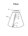
- a scan head 10 containing a multielement transducer 10a transmits ultrasonic pulses into a sector area 26 of the body of a patient.
- a driver 12 actuates the individual elements of the transducer at predetermined times designated by pulse timing circuitry 15 for the transmission of pulses of desired frequencies, lengths, and pulse shapes as designated by pulse shaper 13.
- the characteristics of pulse shaping and pulse timing are under control of a beamformer 16 such that pulses are appropriately shaped and steered along predetermined lines or vectors into the sector 26.
- FIGURE 2 illustrates a spatial vector V n along which pulses are transmitted to insonify a sequence of sample volumes C 1 , C 2 , C 3 , ... C n spatially located along that vector.
- Echoes returning from the sample volumes in response to each pulse transmission are converted into electrical signals by the transducer 10a.
- the electrical echo signals are amplified and digitized into discrete echo samples by a receiver 14.
- the digitized echo signals are appropriately delayed, weighted and combined by the beamformer 16 to form a sequential line of coherent echo information samples from along the vector V n in response to each transmitted pulse.
- the echo information samples produced by the beamformer 16 are initially at RF frequencies.
- the information is transformed into complex form by a demodulator and filter 18 which also demodulates the information to a lower frequency range.
- a demodulator and filter 18 which also demodulates the information to a lower frequency range.
- the principles of the present invention can be applied to demodulated Doppler information signals, or to undemodulated (RF) Doppler information signals using the analytic (complex) form of the RF signal; the utilization of demodulation in the illustrated embodiment is dictated by data handling requirements and other considerations not germane to the present invention.
- the sequence of echo information samples is initially processed by a wall filter and motion elimination processor 20. Details of the wall filter and motion elimination processor may be found in U.S. Patent 5,197,477.
- Each line of echo information samples taken along the spatial vector V n is stored in one vertical column of a two dimensional array store 22.
- a portion of the line sequence of samples may be designated as a unique sample volume by a depth dependent range gate signal enabling the array store, and the gated samples are clocked into the store 22 by an I,Q sample clock.
- the separate lines in the store 22 are aligned horizontally as a function of depth so that each horizontal row across the columns corresponds to samples taken from the same depth along the vector V n .
- the full line of samples is stored and later partitioned into sample volume ranges, and depth alignment is provided by sampling each returning line at the same depth dependent sampling times.
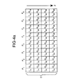
- the samples taken from vector V n by separate pulses P m are stored in the two dimensional array store 22 as shown in FIGURE 3.
- the store 22 spatially and temporally corresponds to the vector V n in that the vertical dimension of the store corresponds to depth along the vector and the horizontal dimension of the store corresponds to the pulse insonifications of the vector.
- eight lines were acquired by the transmission of eight pulses numbered P 1 through P 8 .
- the column of I and Q samples below each pulse number represents the samples taken for that particular line.
- the pulses were transmitted at pulse time intervals T s .
- the samples down each column, which were acquired at increasing depths z along the vector V n were acquired by a sampling clock t by which each successive sample is separated in time from the previous one by sampling period t s .
- FIGURE 3 shows a portion of the two dimensional array store 22 which has been partitioned into contiguous sample volumes. A portion of the samples of sample volumes C 1 and C 3 are shown, and the entire subarray of samples comprising sample volume C 2 is shown. Each sample has an I and a Q component with the same subscripts of the form ly x ,Qy x where y designates the line sampling time (at intervals t s ) and x designates the pulse number (m of P m ).
- sample volume C 2 is seen to be a two dimensional window of samples having a vertical dimension which is depth and a horizontal dimension which is the pulse time.
- the C 2 window is seen to be an eight by eight array of sixty-four samples.
- the samples of the C 2 window are used to estimate the velocity of flow at the sample volume C 2 by performing two dimensional autocorrelation.
- a row autocorrelator 32 operates upon the samples in the C 2 window to determine an autocorrelation function for the Doppler frequency shift as expressed by where WL is the length of the C 2 window (expressed as the general case, Cd in the depth dimension and EL is the number of samples in the time, or ensemble length dimension.
- the index k counts pulses transmitted in the direction of the vector Vn and the index i counts samples in the depth dimension of the sample volume C L .
- a line autocorrelator 34 operates upon the sixty-four samples in the C 2 window to determine an autocorrelation function for the pulse frequency of the sample volume.
- This second autocorrelation can be expressed as
- the row autocorrelator 32 forms products of adjacent or uniformly spaced samples in each horizontal row of the array, the number of such products per row being one less than the number of samples employed.
- the product terms of each row are summed and these sums are accumulated from all the rows to yield the a first autocorrelation function.
- the line autocorrelator 34 forms products of adjacent or uniformly spaced samples in each vertical column of the array, the number of such products per column being one less than the number of samples employed.
- the product terms of each column are summed and these sums are accumulated from all columns to yield a second autocorrelation function.
- the signal samples applied to the autocorrelators can be weighted to further shape the response, as by spatially weighting samples toward the center of the window more greatly than samples at the perimeters.
- Each autocorrelation function is in complex form I+jQ, having both a real and an imaginary term.
- velocity processor 36 the Doppler shift frequency f D and the echo center frequency f c are calculated by computing the arc tangent of the quotient of the imaginary and real terms, divided by the appropriate sampling interval: and
- the estimated velocity value for the sample volume C 2 is then made available for subsequent processing and image formation.
- the generalized expression for higher order lags in determining the Doppler frequency shift can be expressed as where the term P represents the incremental spacing of the higher order lag.
- the expression for computing pulse frequency with a higher order lag would correspondingly show the additional increment in the depth dimension.
- the accuracy of the estimation is determined principally by the number of pulses in the ensemble of pulses interrogating the sample volume. Each pulse and consequent sample adds another sample to the sequence of samples upon which autocorrelation is performed. Increase the number of pulses in the ensemble and accuracy improves; decrease the number of pulses and accuracy decreases. Increased accuracy is seen to come, however, at the expense of greater acquisition time, resulting in slower frame rates.
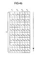
- FIGURES 4a and 4b illustrate two different sample windows for a sample volume C.
- the sample window of FIGURE 4a has four samples in the depth dimension along each line and was acquired in eight lines in response to eight pulse transmissions.
- the sample window of FIGURE 4b has eight samples in the depth dimension and was acquired in four pulse intervals.
- a color flow map composed of sample volume windows such as that of FIGURE 4a will have greater spatial resolution than that of FIGURE 4b by reason of the smaller size of the sample length in the depth dimension.
- Acolorflow map composed of sample volume windows such as FIGURE 4b will have greater temporal resolution than that of FIGURE 4a by reason of the fewer pulse transmission, resulting in a higher frame rate.
- a tradeoff has been made favoring either spatial or temporal resolution.
- the accuracy of the velocity estimate from each window is the same, however, as the number of samples in each window is a constant.
- the two dimensional autocorrelation technique of the present invention can offer improved accuracy and noise performance in comparison with conventional one dimensional Doppler autocorrelation by reason of the fact that the inventive technique utilizes the full information present in the bandwidth of the received echo signals. Unlike one dimensional autocorrelation, the accuracy and noise performance of the technique of the present invention improves with broader band pulses. In comparison with two dimensional Fourier transformation, the two dimensional autocorrelation technique is less sensitive to noise, does not require two sequential estimations (Fourier transformation followed by radial projection), and is less computationally intensive. Accordingly it is better suited to color flow mapping and M mode Doppler applications than either prior art technique.
- analytic techniques may be used to operate upon the two dimensional array of samples of FIGURE 3, 4a or 4b in order to calculate estimates of the RF frequency and Doppler shift terms.
- an analytic technique which calculates instantaneous phase change from sample to sample in the array such as by measuring the instantaneous phase at each sample, taking differences between adjacent sample phases across each row, accumulating the differences, and averaging the accumulation to compute an estimate of Doppier shift.
- differences are taken between adjacent sample phases down each column, these differences are accumulated and averaged, and an estimate of RF frequency is computed.
- the estimates from the array of Doppler shift and RF frequency are then used in the velocity equation to calculate a velocity at the sample volume from which the array of samples was acquired.
Abstract
Description
- This invention relates to ultrasonic diagnostic systems which measure the flow of fluids by pulsed Doppler interrogation and, in particular, to the processing of pulsed Doppler information signals using two dimensional autocorrelation.
- Ultrasonic diagnostic systems which measure the flow of fluids through Doppler interrogation are in widespread use for the acquisition of medical patient data concerning the flow of blood and other fluids in the body. Doppler flow measurement systems may be characterized on the basis of the technique of ultrasonic wave transmission employed, which may be either continuous or pulsed wave transmission. In a continuous wave Doppler system a wave of ultrasonic energy is continuously transmitted toward the target area. Returning echo signals are compared in phase or frequency to the transmitted wave with the shift in phase or frequency being proportionate to the velocity of the target along the axis of transmission. In a pulsed Doppler system a sequence of ultrasonic wave pulses are transmitted toward the target area and the relative phase or frequency shift from one echo to another is calculated and is proportional to the velocity of fluid flow. The Doppler frequency shift fD is given by the Doppler velocity equation

where fo is the frequency of the ultrasonic wave applied to the target, V is the velocity of the target which produced the echo, 0 is the angle of the axis of transmission relative to the direction of motion of the target, and C is the propagation velocity of the transmitted pulse. From this equation it is seen that the Doppler frequency shift fD is proportional to the velocity V of the moving target. - In pulsed Doppler systems the returning echo signals are generally not compared in phase or frequency to a specific continuous reference signal. Instead, the Doppler frequency information manifests itself in the repetition of the transmitted pulses, which are transmitted at sampling times Ts and exhibit a repetition frequency known as the pulse repetition frequency or PRF. A sequence or ensemble of pulses produces a corresponding time sequence of data values for analysis. To extract the Doppler frequency information the received echo signals are analyzed as a function ofTs. Two common processors which serve this purpose are fast Fourier transform and autocorrelation processors. These processors are one dimensional, as the echoes received from each sample volume are reduced to one data value per pulse interval Ts. Examples of autocorrelation processing of Doppler signals may be found in U.S. Patents 4,573,477, 4,905,206, and 4,930,513.
- One current adaptation of Doppler measurement which makes intensive use of Doppler signal processing is color flow mapping. In color flow mapping, an area of the body such as the heart is repetitively interrogated with ultrasonic waves and returning echo signals are compared to determine the velocity of blood flow. This interrogation is performed over a two-dimensional sector of the heart to determine flow velocities at all of the points offlow in the sector, called sample volumes, throughout the interrogated area. The resultant flow velocity values are then displayed in a color image format as a function of measurement location, where different shades and intensities of color represent blood flow of different velocities and directions at each point in the image where flow is occurring. Color flow mapping systems provide a real-time color-encoded display of the mean axial velocity component of flow within each sample volume in the image.
- In order to yield an accurate estimate of flow velocity in the foregoing Doppler velocity equation it is desirable to know as precisely as possible the frequency of the transmitted pulse, fo. Since this frequency is meant to be the center frequency of the pulse which actually insonifies the sample volume, the transmitted pulse length is generally long, giving a narrow, sharply defined bandwidth to the transmitted pulse. However, this conventional narrowband approach to Doppler signal transmission runs contrary to the demands of B mode imaging, where broad bandwidths with high frequency content are desired for good axial resolution and accurate tissue signature identification.
- A number of approaches have been proposed which are broadband in nature, thereby addressing the preceding shortcoming of narrowband processing techniques. These approaches estimate the axial velocity of moving targets by operating on a two dimensional data set of the received echo signals. One of these approaches, shown in U.S. Patents 4,803,990 and 4,928,698, operates in the time domain by performing a crosscorrelation of successive lines of echoes taken rapidly along a common transmission axis. This technique looks for the peak of the crosscorrelation function corresponding to the best match between the two lines of echoes after a relative time shifting of the two lines. While this technique is generally accurate when detecting single velocity flow, it is subject to the production of false peaks when a number of different flow velocity components are present at the sample volume. Another two dimensional technique is shown in U.S. Patents 4,930,513 and 5,048,528 in which successive lines of echoes are processed by two dimensional Fourier transformation. A two dimensional array of echo data is Fourier transformed as a function of Doppler frequency and RF frequency to yield an array of discrete Fourier transform sample points in the frequency domain. In this Fourier frequency domain, constant velocity Doppler spectral components are represented as radial lines and the transformed echoes are mapped as generally elliptical spread of sample points. To calculate velocity a radial projection is made through the major axis of the elliptical spread of points, with the angle of the radial projection being associated with the velocity of the target. While the two dimensional Fourier transformation technique is broadband in nature, it is also computationally intensive, a drawback in economical real-time systems. Moreover, the Fourier technique requires compound estimations, a Fourier transformation followed by a radial projection in Fourier space.
- Other broadband processing techniques which have been proposed in the literature include maximum likelihood estimators which are based on a matched filter approach that takes into account all velocities present in the signal; interpolation methods which rely on a model of the expected correlation between RF echo lines and a few measured sampling intervals to estimate the mean time shift; and angle- independent velocity estimation techniques.
- Broadband pulse techniques are subject to two further phenomena which can lead to inaccuracy in the estimation of the Doppler frequency shift. One is the attenuation of higher transmit frequencies as a function of tissue depth. This rolling off of the higher frequency content of received echoes with depth can result in a continual shifting of the center frequency of received echoes to lower frequencies as a function of the depth from which they were received. A second phenomenon is due to the coherent nature of ultrasonic waves. Echoes returning from scatterers in the vicinity of the target area can destructively interfere with each other, resulting in the elimination of components of the received signal spectrum. Components at the centerfrequency can undergo such cancellation, thereby distorting or changing the spectrum of the received echo signals. A Doppler processing system should provide a means for accurate determination of the actual centerfrequency of the echo signals emanating from the sample volume at every different sample volume in the color flow map, in spite of the effects of these phenomena.
- In accordance with the principles of the present invention, a processing technique for pulsed Doppler echo information is provided which exhibits increased accuracy with broadband pulse transmission. A number of pulses are transmitted to a sample volume at regular sampling intervals Ts and the received lines of echo signals are sampled as a function of depth, stored and operated upon in a two dimensional array format, where one dimension corresponds to depth and the other dimension corresponds to the pulse intervals. A two dimensional autocorrelation is then performed on the array in these two dimensions. The autocorrelation processing in the depth dimension yields a correlation function related to the mean centerfrequency fc of the echoes of the sample volume, and the autocorrelation processing in the pulse interval dimension yields a correlation function related to the mean Doppler shift frequency fD. Mean axial velocity is then estimated using the analytically derived values of fc and fD in the Doppler velocity equation. The technique advantageously utilizes autocorrelation techniques efficiently applied to Doppler velocity estimation and overcomes the shortcoming of the time domain technique of false velocity peak estimation. In comparison with the autocorrelation approaches of the prior art, the present technique exhibits better performance under conditions of slow flow, better temporal and spatial resolution, and improved noise sensitivity.
- In the drawings:
- FIGURE 1 illustrates in block diagram form a two dimensional Doppler autocorrelation processing system constructed in accordance with the principles of the present invention;
- FIGURE 2 illustrates the spatial location of sample volumes in a scan plane of a scanhead;
- FIGURE 3 is a two dimensional array of complex echo information samples from a number of interrogating pulse repetitions; and
- FIGURES 4a and 4b illustrate signal sample array windows which provide differing spatial and temporal resolution when processed in accordance with the principles of the present invention.
- For a number of years autocorrelation processing has been a primary technique for estimating Doppler frequency shifts utilized in color flow mapping. Autocorrelation processing is often preferred for computation- intensive color flow mapping in place of the fast Fourier transform (FFT) spectral estimation technique which has long been in use for Doppler measuring systems which preceded color flow mapping. The principles of autocorrelation processing of Doppler signals are well know. A narrowband (long duration) ultrasonic pulse is transmitted toward a target or discrete sample volume within the body. The echo signal returning from the sample volume is received and demodulated, usually into I and Q quadrature components. This transmit-receive sequence is followed by a number of like sequences separated from the first and from one another by time intervals Ts; the frequency of pulses at intervals Ts is the pulse repetition frequency PRF. The group of pulses transmitted to a particular sample volume is called an ensemble, and the number of pulses in the group is referred to herein as the ensemble length. The signals from the sample volume are then processed by one dimensional autocorrelation in the sequence in which they were received. When represented by subscripts denoting the sequence of reception, the sequence would appear as
-


where Xk=lk+jQk and n is the number of samples in the sequence. From the complex result the Doppler phase shift 0D is calculated as the arc tangent of the quotient of Q' and I', or
- The Doppler frequency shift fD is determined by dividing the phase shift 0D by the product of the pulse interval T and 2π. The velocity of the target is then estimated from the Doppler velocity equation using the estimated value for fD and assuming fo to be the center frequency of the transmitted pulses.
- The use of one dimensional autocorrelation processing is imprecise and limiting in several respects, however. Narrowband transmission pulses of long duration are employed to maintain, to as great a degree as possible, an equivalency between the pulse transmission frequency and the frequency of the echo pulses emanating from the target area. This enables one to ascribe minimal credence to the assumption offo as being equal to the pulse frequency which actually insonifies the target. But due to depth dependent attenuation higherfre- quency components of the echo signal and the center frequency of the received echo signal frequencies are continually decreasing as echoes are received from greater and greater depths. Even at shallow depths the band of echo frequencies can exhibit irregularities in signal content due to coherent interference of signal components concurrently returning from a number of scatterers in the target area. These factors cast aspersions on the assumption of equality between the transducer frequency and the target insonification frequencies that actually reach the sample volume. When broadband, higher frequency content pulses are employed for greater resolution or compatibility with imaging pulse techniques, the dilemma is exacerbated. As the pulses are shortened and their bandwidth is broadened, the accuracy of the one dimensional autocorrelator deteriorates. Furthermore, the performance of one dimensional autocorrelation deteriorates significantly under noise conditions, particularly for small frequency shifts corresponding to low velocity flow. Moreover, the accuracy of one dimensional autocorrelation is dependent upon the use of a significant number of samples taken over an equal number of pulse intervals Ts. As the number of sampling intervals is reduced, the accuracy of the technique declines correspondingly. This limits the performance and flexibility of the frame rate and/or line density performance of the color flow mapping system.
- An embodiment of the present invention overcomes these limitations by acquiring a two dimensional array of signal samples for a sample volume rather than a single sequence of samples. The two dimensions of the array are depth, or the sampling interval direction of the echo signals and the pulse time dimension, the direction of time intervals Ts. Two autocorrelation calculations are performed, one in each of these orthogonal dimensions of the array of signal samples. The autocorrelation in the pulse time dimension yields an autocorrelation function related to the Doppler frequency, and the autocorrelation in the depth dimension yields an autocorrelation function related to the frequency of the received echo signals. The two empirically determined frequencies are then employed in the Doppler velocity estimation to give an estimate of the velocity of motion at the given sample volume.
- Unlike the one dimensional autocorrelation technique, the technique of the present invention preferably employs broadband transmit pulses compatible with those commonly employed in ultrasonic imaging. Because an embodiment of the present invention utilizes the full information present in the bandwidth of the received echo signal, its performance improves as the bandwidth is increased. Rather than assuming a constant value for the pulse insonification frequency, the autocorrelation in the depth dimension empirically estimates the true center frequency of the echo signals received from the sample volume in question. This estimation will account for any depth dependent frequency decline or coherent signal component cancellation. Moreover, an embodiment of the present invention will provide better slow flow performance and noise sensitivity as compared with equivalent one dimensional autocorrelation. Furthermore, the window of array samples can be varied in shape, as discussed below in greater detail, to offer performance tradeoffs in frame rate versus axial resolution while maintaining constant Doppler accuracy.
- Mathematically, the present invention can be described as follows. A target area is interrogated with a number of transmitted pulses with a repetition interval of Ts. The line of echo signals returning after each pulse transmission is sampled at sampling intervals ts, either in the RF frequency domain or after demodulation. Each line of samples is stored as one column of a two dimensional array store in parallel with the preceding received lines. The lines are aligned as a function of depth so that a row of samples across the columns will correspond to a common depth. This correspondence may be accomplished by maintaining a constant relationship between sampling times and depth of returning echoes for each line. The two dimensional array of samples will thus have orthogonal dimensions of the line sampling intervals t, and the pulse repetition intervals Ts.
- The array is subdivided vertically into one or more windows of samples corresponding to the desired sample volume or volumes. The sample volume will thus be defined by the two dimensional array of samples in the window, which has the vertical dimension of samples in the depth dimension and the horizontal dimension of the number of lines acquired over the pulse repetition intervals Ts. The samples of the sample volume window are then operated upon by two orthogonal autocorrelations in the two dimensions to calculate the mean center frequency fc of the received echo signal and the mean Doppler shift frequency fD at the sample volume. The autocorrelations perform the operations

and
where ts is the autocorrelation spacing in the vertical or depth dimension and Ts is the autocorrelation spacing in the horizontal or ensemble time dimension. Each resulting autocorrelation function can be expressed in complex notation having both real and imaginary terms. - The echo center and Doppler frequencies are then estimated by computing the arc tangents of the quotients of the respective imaginary and real terms of the correlation functions divided by the respective sampling interval:

and
- The velocity of motion in the direction of pulse transmission at the sample volume is then estimated by using fc and fD in the velocity equation v = c.fD/2, fc. If desired, angle correction may be employed in the estimation of off axis velocity as is well known in the art.
- When the inventive technique is applied to demodulated signals, the demodulating frequency fdem must be added to the measured mean RF frequency to account for the demodulating frequency shift of fdem. The full velocity equation would then be expressed as

- An ultrasonic signal processing system embodying the principles of the present invention is shown in block diagram form in FIGURE 1. A
scan head 10 containing amultielement transducer 10a transmits ultrasonic pulses into asector area 26 of the body of a patient. Adriver 12 actuates the individual elements of the transducer at predetermined times designated bypulse timing circuitry 15 for the transmission of pulses of desired frequencies, lengths, and pulse shapes as designated bypulse shaper 13. The characteristics of pulse shaping and pulse timing are under control of abeamformer 16 such that pulses are appropriately shaped and steered along predetermined lines or vectors into thesector 26. FIGURE 2 illustrates a spatial vector Vn along which pulses are transmitted to insonify a sequence of sample volumes C1, C2, C3, ... Cn spatially located along that vector. - Echoes returning from the sample volumes in response to each pulse transmission are converted into electrical signals by the
transducer 10a. The electrical echo signals are amplified and digitized into discrete echo samples by areceiver 14. The digitized echo signals are appropriately delayed, weighted and combined by thebeamformer 16 to form a sequential line of coherent echo information samples from along the vector Vn in response to each transmitted pulse. - The echo information samples produced by the
beamformer 16 are initially at RF frequencies. The information is transformed into complex form by a demodulator and filter 18 which also demodulates the information to a lower frequency range. It should be noted that the principles of the present invention can be applied to demodulated Doppler information signals, or to undemodulated (RF) Doppler information signals using the analytic (complex) form of the RF signal; the utilization of demodulation in the illustrated embodiment is dictated by data handling requirements and other considerations not germane to the present invention. Since flow velocity information is often contaminated by artifacts of tissue motion and relative motional effects between the body and the scanhead, the sequence of echo information samples is initially processed by a wall filter andmotion elimination processor 20. Details of the wall filter and motion elimination processor may be found in U.S. Patent 5,197,477. - Each line of echo information samples taken along the spatial vector Vn is stored in one vertical column of a two
dimensional array store 22. A portion of the line sequence of samples may be designated as a unique sample volume by a depth dependent range gate signal enabling the array store, and the gated samples are clocked into thestore 22 by an I,Q sample clock. The separate lines in thestore 22 are aligned horizontally as a function of depth so that each horizontal row across the columns corresponds to samples taken from the same depth along the vector Vn. In a preferred embodiment the full line of samples is stored and later partitioned into sample volume ranges, and depth alignment is provided by sampling each returning line at the same depth dependent sampling times. - The samples taken from vector Vn by separate pulses Pm are stored in the two
dimensional array store 22 as shown in FIGURE 3. Thestore 22 spatially and temporally corresponds to the vector Vn in that the vertical dimension of the store corresponds to depth along the vector and the horizontal dimension of the store corresponds to the pulse insonifications of the vector. In this example eight lines were acquired by the transmission of eight pulses numbered P1 through P8. The column of I and Q samples below each pulse number represents the samples taken for that particular line. The pulses were transmitted at pulse time intervals Ts. The samples down each column, which were acquired at increasing depths z along the vector Vn, were acquired by a sampling clock t by which each successive sample is separated in time from the previous one by sampling period ts. - FIGURE 3 shows a portion of the two
dimensional array store 22 which has been partitioned into contiguous sample volumes. A portion of the samples of sample volumes C1 and C3 are shown, and the entire subarray of samples comprising sample volume C2 is shown. Each sample has an I and a Q component with the same subscripts of the form lyx,Qyx where y designates the line sampling time (at intervals ts) and x designates the pulse number (m of Pm). - While the boundaries of the sample volumes are shown as being contiguous it should be understood that the sample volumes could be partitioned to overlap. For instance the upper eight samples in the array of FIGURE 3 could comprise sample volume C1, the lower eight samples could comprise sample volume C3, and the middle eight samples could comprise sample volume C2 (which thus overlaps the lower half of C1 and the upper half of C3.) In the illustrated partitioning of FIGURE 3, sample volume C2 is seen to be a two dimensional window of samples having a vertical dimension which is depth and a horizontal dimension which is the pulse time. The C2 window is seen to be an eight by eight array of sixty-four samples.
- The samples of the C2 window are used to estimate the velocity of flow at the sample volume C2 by performing two dimensional autocorrelation. A
row autocorrelator 32 operates upon the samples in the C2 window to determine an autocorrelation function for the Doppler frequency shift as expressed by
where WL is the length of the C2 window (expressed as the general case, Cd in the depth dimension and EL is the number of samples in the time, or ensemble length dimension. The index k counts pulses transmitted in the direction of the vector Vn and the index i counts samples in the depth dimension of the sample volume CL. - In a similar manner a
line autocorrelator 34 operates upon the sixty-four samples in the C2 window to determine an autocorrelation function for the pulse frequency of the sample volume. This second autocorrelation can be expressed as
- In essence, the
row autocorrelator 32 forms products of adjacent or uniformly spaced samples in each horizontal row of the array, the number of such products per row being one less than the number of samples employed. The product terms of each row are summed and these sums are accumulated from all the rows to yield the a first autocorrelation function. Correspondingly, theline autocorrelator 34 forms products of adjacent or uniformly spaced samples in each vertical column of the array, the number of such products per column being one less than the number of samples employed. The product terms of each column are summed and these sums are accumulated from all columns to yield a second autocorrelation function. If desired, the signal samples applied to the autocorrelators can be weighted to further shape the response, as by spatially weighting samples toward the center of the window more greatly than samples at the perimeters. - Each autocorrelation function is in complex form I+jQ, having both a real and an imaginary term. In
velocity processor 36 the Doppler shift frequency fD and the echo center frequency fc are calculated by computing the arc tangent of the quotient of the imaginary and real terms, divided by the appropriate sampling interval:
and -

velocity processor 36 estimates the velocity at the sample volume C2 from v = c.fD/2fc. The estimated velocity value for the sample volume C2 is then made available for subsequent processing and image formation. - It may be desirable for certain applications that the autocorrelations be computed for higher order lags than single increment sample spacing. The generalized expression for higher order lags in determining the Doppler frequency shift can be expressed as

where the term P represents the incremental spacing of the higher order lag. The expression for computing pulse frequency with a higher order lag would correspondingly show the additional increment in the depth dimension. - In the conventional one dimensional autocorrelation velocity estimator the accuracy of the estimation is determined principally by the number of pulses in the ensemble of pulses interrogating the sample volume. Each pulse and consequent sample adds another sample to the sequence of samples upon which autocorrelation is performed. Increase the number of pulses in the ensemble and accuracy improves; decrease the number of pulses and accuracy decreases. Increased accuracy is seen to come, however, at the expense of greater acquisition time, resulting in slower frame rates.
- With two dimensional autocorrelation processing, however, tradeoffs in temporal and spatial resolution can be made without sacrificing the accuracy of velocity estimation. This is because accuracy is determined by the number of samples in the sample volume window, not solely by the pulse ensemble length. Thus, the shape of the window can be tailored to meet particular performance requirements. FIGURES 4a and 4b illustrate two different sample windows for a sample volume C. The sample window of FIGURE 4a has four samples in the depth dimension along each line and was acquired in eight lines in response to eight pulse transmissions. The sample window of FIGURE 4b has eight samples in the depth dimension and was acquired in four pulse intervals. A color flow map composed of sample volume windows such as that of FIGURE 4a will have greater spatial resolution than that of FIGURE 4b by reason of the smaller size of the sample length in the depth dimension. Acolorflow map composed of sample volume windows such as FIGURE 4b will have greater temporal resolution than that of FIGURE 4a by reason of the fewer pulse transmission, resulting in a higher frame rate. In each case a tradeoff has been made favoring either spatial or temporal resolution. The accuracy of the velocity estimate from each window is the same, however, as the number of samples in each window is a constant.
- The two dimensional autocorrelation technique of the present invention can offer improved accuracy and noise performance in comparison with conventional one dimensional Doppler autocorrelation by reason of the fact that the inventive technique utilizes the full information present in the bandwidth of the received echo signals. Unlike one dimensional autocorrelation, the accuracy and noise performance of the technique of the present invention improves with broader band pulses. In comparison with two dimensional Fourier transformation, the two dimensional autocorrelation technique is less sensitive to noise, does not require two sequential estimations (Fourier transformation followed by radial projection), and is less computationally intensive. Accordingly it is better suited to color flow mapping and M mode Doppler applications than either prior art technique.
- One skilled in the art will recognize that alternative analytic techniques may be used to operate upon the two dimensional array of samples of FIGURE 3, 4a or 4b in order to calculate estimates of the RF frequency and Doppler shift terms. For instance, one could apply an analytic technique which calculates instantaneous phase change from sample to sample in the array such as by measuring the instantaneous phase at each sample, taking differences between adjacent sample phases across each row, accumulating the differences, and averaging the accumulation to compute an estimate of Doppier shift. Likewise, differences are taken between adjacent sample phases down each column, these differences are accumulated and averaged, and an estimate of RF frequency is computed. The estimates from the array of Doppler shift and RF frequency are then used in the velocity equation to calculate a velocity at the sample volume from which the array of samples was acquired.
Claims (19)
Applications Claiming Priority (2)
| Application Number | Priority Date | Filing Date | Title |
|---|---|---|---|
| US142784 | 1980-04-22 | ||
| US08/142,784 US5386830A (en) | 1993-10-25 | 1993-10-25 | Ultrasonic pulsed doppler flow measurement system with two dimensional autocorrelation processing |
Publications (3)
| Publication Number | Publication Date |
|---|---|
| EP0650036A2 true EP0650036A2 (en) | 1995-04-26 |
| EP0650036A3 EP0650036A3 (en) | 1996-01-31 |
| EP0650036B1 EP0650036B1 (en) | 2004-01-21 |
Family
ID=22501264
Family Applications (1)
| Application Number | Title | Priority Date | Filing Date |
|---|---|---|---|
| EP94307502A Expired - Lifetime EP0650036B1 (en) | 1993-10-25 | 1994-10-13 | Ultrasonic pulsed Doppler flow measurement system with two dimensional autocorrelation processing |
Country Status (6)
| Country | Link |
|---|---|
| US (1) | US5386830A (en) |
| EP (1) | EP0650036B1 (en) |
| JP (1) | JPH07250835A (en) |
| AT (1) | ATE258307T1 (en) |
| AU (1) | AU7753394A (en) |
| DE (1) | DE69433497T2 (en) |
Families Citing this family (46)
| Publication number | Priority date | Publication date | Assignee | Title |
|---|---|---|---|---|
| US5454372A (en) * | 1994-06-17 | 1995-10-03 | Siemens Medical Systems, Inc. | Angle independent doppler in ultrasound imaging |
| NO944736D0 (en) * | 1994-12-07 | 1994-12-07 | Vingmed Sound As | Method of determining blood velocity |
| US5957846A (en) * | 1995-06-29 | 1999-09-28 | Teratech Corporation | Portable ultrasound imaging system |
| US7500952B1 (en) | 1995-06-29 | 2009-03-10 | Teratech Corporation | Portable ultrasound imaging system |
| US5964709A (en) * | 1995-06-29 | 1999-10-12 | Teratech Corporation | Portable ultrasound imaging system |
| US5590658A (en) * | 1995-06-29 | 1997-01-07 | Teratech Corporation | Portable ultrasound imaging system |
| US8241217B2 (en) | 1995-06-29 | 2012-08-14 | Teratech Corporation | Portable ultrasound imaging data |
| AU1983397A (en) * | 1996-02-29 | 1997-09-16 | Acuson Corporation | Multiple ultrasound image registration system, method and transducer |
| US5846202A (en) * | 1996-07-30 | 1998-12-08 | Acuson Corporation | Ultrasound method and system for imaging |
| US5669386A (en) * | 1996-07-31 | 1997-09-23 | Hewlett-Packard Company | Ultrasonic flow measurement system employing cross-correlation of baseband reflection data |
| US6030344A (en) * | 1996-12-04 | 2000-02-29 | Acuson Corporation | Methods and apparatus for ultrasound image quantification |
| US6111816A (en) * | 1997-02-03 | 2000-08-29 | Teratech Corporation | Multi-dimensional beamforming device |
| US6721235B2 (en) | 1997-02-03 | 2004-04-13 | Teratech Corporation | Steerable beamforming system |
| US6292433B1 (en) | 1997-02-03 | 2001-09-18 | Teratech Corporation | Multi-dimensional beamforming device |
| US7789841B2 (en) | 1997-02-06 | 2010-09-07 | Exogen, Inc. | Method and apparatus for connective tissue treatment |
| US7108663B2 (en) * | 1997-02-06 | 2006-09-19 | Exogen, Inc. | Method and apparatus for cartilage growth stimulation |
| US6050944A (en) * | 1997-06-17 | 2000-04-18 | Acuson Corporation | Method and apparatus for frequency control of an ultrasound system |
| US6023977A (en) * | 1997-08-01 | 2000-02-15 | Acuson Corporation | Ultrasonic imaging aberration correction system and method |
| US6132374A (en) * | 1997-08-01 | 2000-10-17 | Acuson Corporation | Ultrasonic imaging method and system |
| US5944666A (en) * | 1997-08-21 | 1999-08-31 | Acuson Corporation | Ultrasonic method for imaging blood flow including disruption or activation of contrast agent |
| US6106465A (en) * | 1997-08-22 | 2000-08-22 | Acuson Corporation | Ultrasonic method and system for boundary detection of an object of interest in an ultrasound image |
| US5928151A (en) * | 1997-08-22 | 1999-07-27 | Acuson Corporation | Ultrasonic system and method for harmonic imaging in three dimensions |
| US5873830A (en) * | 1997-08-22 | 1999-02-23 | Acuson Corporation | Ultrasound imaging system and method for improving resolution and operation |
| US5935069A (en) * | 1997-10-10 | 1999-08-10 | Acuson Corporation | Ultrasound system and method for variable transmission of ultrasonic signals |
| US5860931A (en) * | 1997-10-10 | 1999-01-19 | Acuson Corporation | Ultrasound method and system for measuring perfusion |
| US5897500A (en) * | 1997-12-18 | 1999-04-27 | Acuson Corporation | Ultrasonic imaging system and method for displaying composite fundamental and harmonic images |
| US5961462A (en) * | 1998-05-18 | 1999-10-05 | Atl Ultrasound | Ultrasonic doppler imaging at high frame rates of display |
| US6001063A (en) * | 1998-06-23 | 1999-12-14 | Acuson Corporation | Ultrasonic imaging method and apparatus for providing doppler energy correction |
| US6585647B1 (en) | 1998-07-21 | 2003-07-01 | Alan A. Winder | Method and means for synthetic structural imaging and volume estimation of biological tissue organs |
| US6048316A (en) * | 1998-10-16 | 2000-04-11 | Acuson Corporation | Medical diagnostic ultrasonic imaging system and method for displaying composite fundamental and harmonic images |
| JP4574790B2 (en) * | 1999-03-30 | 2010-11-04 | 東芝医用システムエンジニアリング株式会社 | Ultrasonic diagnostic apparatus and ultrasonic diagnostic method |
| US6842401B2 (en) | 2000-04-06 | 2005-01-11 | Teratech Corporation | Sonar beamforming system |
| JP4126228B2 (en) * | 2000-10-25 | 2008-07-30 | エクソジェン インコーポレイテッド | Transmitter mounting assembly |
| JP2006505321A (en) * | 2002-11-06 | 2006-02-16 | コーニンクレッカ フィリップス エレクトロニクス エヌ ヴィ | Phased array acoustic system for 3D imaging of moving parts |
| US7527591B2 (en) * | 2003-11-21 | 2009-05-05 | General Electric Company | Ultrasound probe distributed beamformer |
| US20050113698A1 (en) * | 2003-11-21 | 2005-05-26 | Kjell Kristoffersen | Ultrasound probe transceiver circuitry |
| US7527592B2 (en) * | 2003-11-21 | 2009-05-05 | General Electric Company | Ultrasound probe sub-aperture processing |
| US20050171429A1 (en) * | 2004-01-16 | 2005-08-04 | Mathew Prakash P. | Method and system for very high frame rates in ultrasound B-Mode imaging |
| AU2005205820B2 (en) * | 2004-09-04 | 2011-04-14 | Smith & Nephew Plc | Ultrasound device and method of use |
| US7152490B1 (en) * | 2005-08-15 | 2006-12-26 | Daniel Measurement And Control, Inc. | Methods for determining transducer delay time and transducer separation in ultrasonic flow meters |
| US7591787B2 (en) * | 2005-09-15 | 2009-09-22 | Piero Tortoli | Method for removing Doppler angle ambiguity |
| CN101375178A (en) * | 2006-01-27 | 2009-02-25 | 皇家飞利浦电子股份有限公司 | Automatic ultrasonic doppler measurements |
| US20100228130A1 (en) * | 2009-03-09 | 2010-09-09 | Teratech Corporation | Portable ultrasound imaging system |
| JP7231541B2 (en) | 2016-11-14 | 2023-03-01 | コーニンクレッカ フィリップス エヌ ヴェ | Triple-mode ultrasound imaging for anatomical, functional and hemodynamic imaging |
| CN110456362B (en) * | 2019-07-17 | 2021-07-06 | 北京大学 | Target acoustic imaging and speed measuring method and system based on pulse pair emission |
| CN111189445B (en) * | 2020-01-14 | 2023-05-05 | 哈尔滨工业大学 | Pulsar identification method based on stochastic resonance |
Citations (4)
| Publication number | Priority date | Publication date | Assignee | Title |
|---|---|---|---|---|
| DE3605163A1 (en) * | 1985-02-19 | 1986-08-21 | Hitachi Medical Corp., Tokio/Tokyo | ULTRASONIC DIAGNOSTIC DEVICE |
| EP0228070A2 (en) * | 1985-12-26 | 1987-07-08 | Aloka Co. Ltd. | Ultrasonic doppler diagnostic apparatus |
| US5170791A (en) * | 1991-03-28 | 1992-12-15 | Hewlett-Packard Company | Method and apparatus for calculating the fetal heart rate |
| US5228009A (en) * | 1992-04-10 | 1993-07-13 | Diasonics, Inc. | Parametric clutter elimination |
Family Cites Families (18)
| Publication number | Priority date | Publication date | Assignee | Title |
|---|---|---|---|---|
| US2053841A (en) * | 1935-08-05 | 1936-09-08 | Continental Oil Co | Method and apparatus for making geophysical explorations |
| US4324258A (en) * | 1980-06-24 | 1982-04-13 | Werner Huebscher | Ultrasonic doppler flowmeters |
| JPS5897347A (en) * | 1981-12-03 | 1983-06-09 | 株式会社東芝 | Ultrasonic diagnostic apparatus |
| JPS58188433A (en) * | 1982-04-28 | 1983-11-02 | アロカ株式会社 | Ultrasonic diagnostic apparatus |
| US4612937A (en) * | 1983-11-10 | 1986-09-23 | Siemens Medical Laboratories, Inc. | Ultrasound diagnostic apparatus |
| JPH0693890B2 (en) * | 1985-04-30 | 1994-11-24 | 株式会社東芝 | Ultrasonic diagnostic equipment |
| US4803990A (en) * | 1985-12-03 | 1989-02-14 | U.S. Philips Corporation | Examining moving objects by ultrasound echograpy |
| US4799490A (en) * | 1986-03-04 | 1989-01-24 | Aloka Co., Ltd. | Doppler ultrasonic diagnostic apparatus |
| US4790323A (en) * | 1986-11-03 | 1988-12-13 | Hewlett-Packard Company | Flow imaging detector |
| JPH01110351A (en) * | 1987-10-23 | 1989-04-27 | Aloka Co Ltd | Ultrasonic doppler diagnostic apparatus |
| US4800891A (en) * | 1987-11-13 | 1989-01-31 | Siemens Medical Laboratories, Inc. | Doppler velocity processing method and apparatus |
| FR2629997B1 (en) * | 1988-04-19 | 1990-08-17 | Labo Electronique Physique | CORRELATION MEASUREMENT DEVICE FOR SPEED OF MOVING ORGANS AND BLOOD FLOWS |
| US4905206A (en) * | 1988-06-22 | 1990-02-27 | Hitachi Medical Corporation | Ultrasonic doppler flow meter |
| US4972838A (en) * | 1988-07-13 | 1990-11-27 | Kabushiki Kaisha Toshiba | Ultrasonic diagnostic apparatus |
| US4930513A (en) * | 1988-07-26 | 1990-06-05 | U.S. Philips Corporation | Two dimensional processing of pulsed Doppler signals |
| US5197477A (en) * | 1990-10-12 | 1993-03-30 | Advanced Technology Laboratories, Inc. | Ultrasonic doppler flow measurement system with tissue motion discrimination |
| US5048528A (en) * | 1990-11-15 | 1991-09-17 | North American Philips Corp. | Alias suppression in pulsed doppler systems |
| US5121364A (en) * | 1991-08-07 | 1992-06-09 | General Electric Company | Time frequency control filter for an ultrasonic imaging system |
-
1993
- 1993-10-25 US US08/142,784 patent/US5386830A/en not_active Expired - Lifetime
-
1994
- 1994-10-13 EP EP94307502A patent/EP0650036B1/en not_active Expired - Lifetime
- 1994-10-13 AT AT94307502T patent/ATE258307T1/en not_active IP Right Cessation
- 1994-10-13 DE DE69433497T patent/DE69433497T2/en not_active Expired - Fee Related
- 1994-10-25 JP JP6283920A patent/JPH07250835A/en not_active Ceased
- 1994-10-28 AU AU77533/94A patent/AU7753394A/en not_active Abandoned
Patent Citations (4)
| Publication number | Priority date | Publication date | Assignee | Title |
|---|---|---|---|---|
| DE3605163A1 (en) * | 1985-02-19 | 1986-08-21 | Hitachi Medical Corp., Tokio/Tokyo | ULTRASONIC DIAGNOSTIC DEVICE |
| EP0228070A2 (en) * | 1985-12-26 | 1987-07-08 | Aloka Co. Ltd. | Ultrasonic doppler diagnostic apparatus |
| US5170791A (en) * | 1991-03-28 | 1992-12-15 | Hewlett-Packard Company | Method and apparatus for calculating the fetal heart rate |
| US5228009A (en) * | 1992-04-10 | 1993-07-13 | Diasonics, Inc. | Parametric clutter elimination |
Also Published As
| Publication number | Publication date |
|---|---|
| US5386830A (en) | 1995-02-07 |
| JPH07250835A (en) | 1995-10-03 |
| DE69433497T2 (en) | 2004-12-02 |
| AU7753394A (en) | 1995-05-11 |
| ATE258307T1 (en) | 2004-02-15 |
| EP0650036A3 (en) | 1996-01-31 |
| EP0650036B1 (en) | 2004-01-21 |
| DE69433497D1 (en) | 2004-02-26 |
Similar Documents
| Publication | Publication Date | Title |
|---|---|---|
| US5386830A (en) | Ultrasonic pulsed doppler flow measurement system with two dimensional autocorrelation processing | |
| US20240081787A1 (en) | Motion detection using ping-based and multiple aperture doppler ultrasound | |
| US5107841A (en) | Maximum entropy velocity estimator for ultrasonic flow imaging system | |
| US5454372A (en) | Angle independent doppler in ultrasound imaging | |
| EP0358249B1 (en) | Method and apparatus for fourier processing of pulsed doppler signals | |
| US6860854B2 (en) | Synthetically focused ultrasonic diagnostic imaging system for tissue and flow imaging | |
| Walker et al. | A fundamental limit on delay estimation using partially correlated speckle signals | |
| US5899861A (en) | 3-dimensional volume by aggregating ultrasound fields of view | |
| US7238158B2 (en) | Pulse interleaving in doppler ultrasound imaging | |
| US5961462A (en) | Ultrasonic doppler imaging at high frame rates of display | |
| EP2830508B1 (en) | Methods and apparatus for ultrasound imaging | |
| US5606972A (en) | Ultrasonic doppler measurement of blood flow velocities by array transducers | |
| EP0008517A1 (en) | Duplex ultrasonic imaging system with repetitive excitation of common transducer in Doppler modality | |
| Torp et al. | Autocorrelation techniques in color flow imaging: Signal model and statistical properties of the autocorrelation estimates | |
| EP2691026A2 (en) | Methods and apparatus for ultrasound imaging | |
| WO2004042424A1 (en) | Phased array acoustic system for 3d imaging of moving parts_____ | |
| EP2555685A2 (en) | Methods and apparatus for ultrasound imaging | |
| Wilson | Description of broad-band pulsed Doppler ultrasound processing using the two-dimensional Fourier transform | |
| US6364838B1 (en) | Pulsed wave doppler processing using aliased spectral data | |
| US6293914B1 (en) | Ultrasonic system and method for measurement of fluid flow | |
| US20040220474A1 (en) | Determining the power of an ultrasound reflection using an autocorrelation technique | |
| EP0521498B1 (en) | Elutter rejection filter for an ultrasonic doppler system | |
| WO1995021572A1 (en) | Estimating target velocity from pulse echoes | |
| Jensen | Artifacts in blood velocity estimation using ultrasound and cross-correlation | |
| El-Fallah et al. | Ultrasonic measurement of breast tissue motion and the implications for velocity estimation |
Legal Events
| Date | Code | Title | Description |
|---|---|---|---|
| PUAI | Public reference made under article 153(3) epc to a published international application that has entered the european phase |
Free format text: ORIGINAL CODE: 0009012 |
|
| AK | Designated contracting states |
Kind code of ref document: A2 Designated state(s): AT BE CH DE DK ES FR GB GR IE IT LI LU MC NL PT SE |
|
| RTI1 | Title (correction) | ||
| PUAL | Search report despatched |
Free format text: ORIGINAL CODE: 0009013 |
|
| AK | Designated contracting states |
Kind code of ref document: A3 Designated state(s): AT BE CH DE DK ES FR GB GR IE IT LI LU MC NL PT SE |
|
| 17P | Request for examination filed |
Effective date: 19960705 |
|
| RAP1 | Party data changed (applicant data changed or rights of an application transferred) |
Owner name: THE COMMONWEALTH SCIENTIFIC AND INDUSTRIAL RESEAR Owner name: ADVANCED TECHNOLOGY LABORATORIES, INC. |
|
| 17Q | First examination report despatched |
Effective date: 19991020 |
|
| GRAH | Despatch of communication of intention to grant a patent |
Free format text: ORIGINAL CODE: EPIDOS IGRA |
|
| GRAS | Grant fee paid |
Free format text: ORIGINAL CODE: EPIDOSNIGR3 |
|
| GRAA | (expected) grant |
Free format text: ORIGINAL CODE: 0009210 |
|
| AK | Designated contracting states |
Kind code of ref document: B1 Designated state(s): AT BE CH DE DK ES FR GB GR IE IT LI LU MC NL PT SE |
|
| PG25 | Lapsed in a contracting state [announced via postgrant information from national office to epo] |
Ref country code: NL Free format text: LAPSE BECAUSE OF FAILURE TO SUBMIT A TRANSLATION OF THE DESCRIPTION OR TO PAY THE FEE WITHIN THE PRESCRIBED TIME-LIMIT Effective date: 20040121 Ref country code: LI Free format text: LAPSE BECAUSE OF FAILURE TO SUBMIT A TRANSLATION OF THE DESCRIPTION OR TO PAY THE FEE WITHIN THE PRESCRIBED TIME-LIMIT Effective date: 20040121 Ref country code: IT Free format text: LAPSE BECAUSE OF FAILURE TO SUBMIT A TRANSLATION OF THE DESCRIPTION OR TO PAY THE FEE WITHIN THE PRESCRIBED TIME-LIMIT;WARNING: LAPSES OF ITALIAN PATENTS WITH EFFECTIVE DATE BEFORE 2007 MAY HAVE OCCURRED AT ANY TIME BEFORE 2007. THE CORRECT EFFECTIVE DATE MAY BE DIFFERENT FROM THE ONE RECORDED. Effective date: 20040121 Ref country code: FR Free format text: LAPSE BECAUSE OF FAILURE TO SUBMIT A TRANSLATION OF THE DESCRIPTION OR TO PAY THE FEE WITHIN THE PRESCRIBED TIME-LIMIT Effective date: 20040121 Ref country code: CH Free format text: LAPSE BECAUSE OF FAILURE TO SUBMIT A TRANSLATION OF THE DESCRIPTION OR TO PAY THE FEE WITHIN THE PRESCRIBED TIME-LIMIT Effective date: 20040121 Ref country code: BE Free format text: LAPSE BECAUSE OF FAILURE TO SUBMIT A TRANSLATION OF THE DESCRIPTION OR TO PAY THE FEE WITHIN THE PRESCRIBED TIME-LIMIT Effective date: 20040121 Ref country code: AT Free format text: LAPSE BECAUSE OF FAILURE TO SUBMIT A TRANSLATION OF THE DESCRIPTION OR TO PAY THE FEE WITHIN THE PRESCRIBED TIME-LIMIT Effective date: 20040121 |
|
| REG | Reference to a national code |
Ref country code: GB Ref legal event code: FG4D |
|
| REG | Reference to a national code |
Ref country code: CH Ref legal event code: EP |
|
| REG | Reference to a national code |
Ref country code: IE Ref legal event code: FG4D Ref country code: GB Ref legal event code: 746 Effective date: 20040202 |
|
| REF | Corresponds to: |
Ref document number: 69433497 Country of ref document: DE Date of ref document: 20040226 Kind code of ref document: P |
|
| PG25 | Lapsed in a contracting state [announced via postgrant information from national office to epo] |
Ref country code: SE Free format text: LAPSE BECAUSE OF FAILURE TO SUBMIT A TRANSLATION OF THE DESCRIPTION OR TO PAY THE FEE WITHIN THE PRESCRIBED TIME-LIMIT Effective date: 20040421 Ref country code: GR Free format text: LAPSE BECAUSE OF FAILURE TO SUBMIT A TRANSLATION OF THE DESCRIPTION OR TO PAY THE FEE WITHIN THE PRESCRIBED TIME-LIMIT Effective date: 20040421 Ref country code: DK Free format text: LAPSE BECAUSE OF FAILURE TO SUBMIT A TRANSLATION OF THE DESCRIPTION OR TO PAY THE FEE WITHIN THE PRESCRIBED TIME-LIMIT Effective date: 20040421 |
|
| PG25 | Lapsed in a contracting state [announced via postgrant information from national office to epo] |
Ref country code: ES Free format text: LAPSE BECAUSE OF FAILURE TO SUBMIT A TRANSLATION OF THE DESCRIPTION OR TO PAY THE FEE WITHIN THE PRESCRIBED TIME-LIMIT Effective date: 20040502 |
|
| NLV1 | Nl: lapsed or annulled due to failure to fulfill the requirements of art. 29p and 29m of the patents act | ||
| REG | Reference to a national code |
Ref country code: CH Ref legal event code: PL |
|
| PG25 | Lapsed in a contracting state [announced via postgrant information from national office to epo] |
Ref country code: LU Free format text: LAPSE BECAUSE OF NON-PAYMENT OF DUE FEES Effective date: 20041013 Ref country code: IE Free format text: LAPSE BECAUSE OF NON-PAYMENT OF DUE FEES Effective date: 20041013 |
|
| PGFP | Annual fee paid to national office [announced via postgrant information from national office to epo] |
Ref country code: GB Payment date: 20041028 Year of fee payment: 11 |
|
| PG25 | Lapsed in a contracting state [announced via postgrant information from national office to epo] |
Ref country code: MC Free format text: LAPSE BECAUSE OF NON-PAYMENT OF DUE FEES Effective date: 20041031 |
|
| PLBE | No opposition filed within time limit |
Free format text: ORIGINAL CODE: 0009261 |
|
| STAA | Information on the status of an ep patent application or granted ep patent |
Free format text: STATUS: NO OPPOSITION FILED WITHIN TIME LIMIT |
|
| 26N | No opposition filed |
Effective date: 20041022 |
|
| EN | Fr: translation not filed | ||
| EN | Fr: translation not filed | ||
| PG25 | Lapsed in a contracting state [announced via postgrant information from national office to epo] |
Ref country code: DE Free format text: LAPSE BECAUSE OF NON-PAYMENT OF DUE FEES Effective date: 20050503 |
|
| REG | Reference to a national code |
Ref country code: FR Ref legal event code: ERR Free format text: BOPI DE PUBLICATION N: 05/03 PAGES: 237 PARTIE DU BULLETIN CONCERNEE: BREVETS EUROPEENS DONT LA TRADUCTION N'A PAS ETE REMISE A I'INPI IL Y A LIEU DE SUPPRIMER: LA MENTION DE LA NON REMISE. |
|
| PG25 | Lapsed in a contracting state [announced via postgrant information from national office to epo] |
Ref country code: GB Free format text: LAPSE BECAUSE OF NON-PAYMENT OF DUE FEES Effective date: 20051013 |
|
| REG | Reference to a national code |
Ref country code: IE Ref legal event code: MM4A |
|
| GBPC | Gb: european patent ceased through non-payment of renewal fee |
Effective date: 20051013 |
|
| PG25 | Lapsed in a contracting state [announced via postgrant information from national office to epo] |
Ref country code: PT Free format text: LAPSE BECAUSE OF NON-PAYMENT OF DUE FEES Effective date: 20040621 |