EP0650134B1 - Barcodeleser und Verfahren zu seinem Betrieb - Google Patents
Barcodeleser und Verfahren zu seinem Betrieb Download PDFInfo
- Publication number
- EP0650134B1 EP0650134B1 EP94115763A EP94115763A EP0650134B1 EP 0650134 B1 EP0650134 B1 EP 0650134B1 EP 94115763 A EP94115763 A EP 94115763A EP 94115763 A EP94115763 A EP 94115763A EP 0650134 B1 EP0650134 B1 EP 0650134B1
- Authority
- EP
- European Patent Office
- Prior art keywords
- scanning
- article
- scanner
- light beam
- scanned surface
- Prior art date
- Legal status (The legal status is an assumption and is not a legal conclusion. Google has not performed a legal analysis and makes no representation as to the accuracy of the status listed.)
- Expired - Lifetime
Links
Images

Classifications
-
- G—PHYSICS
- G06—COMPUTING; CALCULATING OR COUNTING
- G06K—GRAPHICAL DATA READING; PRESENTATION OF DATA; RECORD CARRIERS; HANDLING RECORD CARRIERS
- G06K7/00—Methods or arrangements for sensing record carriers, e.g. for reading patterns
- G06K7/10—Methods or arrangements for sensing record carriers, e.g. for reading patterns by electromagnetic radiation, e.g. optical sensing; by corpuscular radiation
Definitions
- the invention relates to a method for operating a Barcode reader according to the preamble of claim 1 and a barcode reader according to the preamble of claim 4.
- Barcode readers of this type are used in the transportation of General cargo, e.g. when conveying parcels or pieces of luggage on a conveyor belt, used to on the conveyed good recognize the appropriate bar codes and accordingly To be able to process the material being conveyed.
- Such barcode readers are generally next to the trajectory of the Conveyed goods arranged, and there is no problem that Side surfaces or the top surface of a funded Scanning the object with a scanner.
- Barcode readers give one to the Scanning surface of the object directed scanning light beam a double scanning movement perpendicular to each other standing directions, such that initially a high Frequency of e.g. 1 KHz along a scan line Scanning light beam a linear area on the Scanned area and that the scan line thus formed slow, i.e. for example within 0.1 to 2 seconds in the direction perpendicular to the scanning line over the Scanning surface is advanced so that each point of the Scanned area captured at least once by the scanning light beam becomes.
- a high Frequency e.g. 1 KHz along a scan line Scanning light beam a linear area on the Scanned area and that the scan line thus formed slow, i.e. for example within 0.1 to 2 seconds in the direction perpendicular to the scanning line over the Scanning surface is advanced so that each point of the Scanned area captured at least once by the scanning light beam becomes.
- the scanning light beam according to the invention now obliquely from in front or at an angle from behind onto the front and / or back scanning surface falls, changes during the scanning process the distance between the scanner and the scanning surface.
- the one on the Scanned light beam focused must therefore be a have sufficient depth of field, so also with yourself changing scanning distances always a sufficient sharpness of the There is a scanning light spot on the scanning surface.
- the Generation of a scanning light beam with great depth of field requires a high optical effort, which also with a comparatively voluminous structure of the scanner is linked.
- the aim of the present invention is to provide a another barcode reader and another method for his To create operation.
- the problem of Depth of field of such a barcode reader when scanning the front and / or rear scanning surface of a moving Object to be solved in a low-cost manner.
- the idea of the invention is that the Speed of movement of the objects Conveyor and the feed rate of the scanning line or the scanning area, in particular the scanning sector, so be coordinated so that the scan line is in each phase of the scanning process at least substantially the same distance from the scanner. That way dispenses with a scanner with a large depth of field be, so that a scanner of simple optical construction is sufficient for the purposes of the invention.
- the Synchronization of conveyor speed and Feed rate of the scanning line can be increased simple way by detecting the front or rear Scanning area of the object and the control of the Scan line feed depending on the Realize the speed of movement of the object.
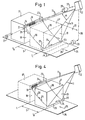
- 1 is an object 17 on a conveyor belt 35 arranged to from the in solid lines reproduced position in a direction of movement 26 to be promoted. At 17 'the same item is after the feed by a distance S a second time reproduced.
- a barcode stuck on which contains information necessary for e.g. a later sorting of the items 17 is important. It can e.g. information about the destination act on a checked package. So that the package 17 can be sorted correctly later, must be from the sorting point read the location information contained in barcode 16 and be recognized.
- S is in front of the reading range above Path of motion 20 of objects 17 preferably with arranged a laser-equipped scanner 12, which one Scanning light beam 11 in the direction of the front surface 18 sends out.
- the scanning light beam 11 leads in the direction of arrow 24 a scanning movement with a frequency of e.g. 1 KHz off and generated by the over the front surface 18th current scanning light spot a scanning line 23.
- the scanning light beam 11 is essential lower frequency of e.g. 0.1 to 2 Hz in the direction of Arrow 25 deflected downward such that the scan line 23 along the circular cylindrical surface 36 with the center in Scanner 12 down towards the conveyor belt 35 is pivoted.
- a light barrier 28 consisting of a light source 27 and a light receiver is provided above the conveyor belt 35, which informs the scanner 12 via a control line 37 as soon as the front surface 18 of an object 17 enters the reading section S at time T 0 .
- the inventive method now consists in that after the light barrier 27, 28 the entry of the front surface 18 of the object 17 in the reading range S recognizes the Laser scanner 12 is controlled via the control line 37 is that the scanning line 23 is initially in the upper region 21 is located near the front upper edge of the article 17. With increasing feed of the object 17 in the direction of Arrow 26 then pivots the scan line 23 controlled by Incremental encoder 29 via the control line 38 along the Circular cylinder surface 36 down until at time T1, to which the scanning surface 18 is the rear end of the reading distance S has reached the lower area 22 in the area has reached the front lower edge of the article 17. This state is in Fig. 1 in dashed lines at 17 ' indicated.
- the length of the reading distance S is now like this chosen that the scanning line 23 in each phase of movement of the Item 17 within the reading range S itself substantially the same distance from the center of the Scanning light beam 11 is located inside the scanner 12.
- the scanning light spot located on the scanning line 23, the at the beginning of the reading section S in the upper area 21 of the Object 17 is shown sharply, so remains during the total feed movement in the direction of arrow 25 sharp even when the depth of field of the Illustration of the scanning light spot is minimal.
- the reading distance S and the feed speed of the Scanning line 23 in the direction of arrow 25 ensures that the distance of the scanning light beam 11 from the center of the Scanning movement within the laser scanner 12 to front surface 18 of the moving object 17 at least in remains essentially constant.
- FIG. 1 A practical embodiment of the scanner 12 according to FIG. 1 is shown schematically in Figs. 2 and 3.
- a laser 39 does not have one Optics shown generated sharply focused light beam 33 runs through a semi-transparent mirror 40 a mirror wheel 32 which is about an axis 41 to a continuous rotation in the direction of the arrow is driven.
- the light beam 33 is at one of the Facets of the mirror wheel deflected by 90 °, for example, um as a reflected light beam 34 to an elongated Swinging mirror 31 to arrive, the length of which is so great that the whole by two dashed lines 34 ', 34' ' limited scanning range of the reflected light beam 34 is detected.
- the oscillating mirror 31 guides the reflected light beam 34 again, towards the front Scanning surface 18 of the object 17, where the barcode 16 is appropriate.
- a drive 30 gives the oscillating mirror 31 a back and forth Movement around one in the direction of its longitudinal axis extending pivot axis 42 in the direction of the double arrow.
- the swinging mirror 31 becomes the front surface 18 cast scanning light beam 11 in a in FIG. 3rd dashed indicated angle range from 11 'to 11' 'back and forth swung here.
- That reflected from the front surface 18 of the object 17 Light is z. B. in autocollimation via the oscillating mirror 31 and the mirror wheel 32 for partially permeable Mirror 40 thrown back and from this to a photo receiver 15 redirected to an evaluation and control electronics 14 is connected.
- the photo receiver 15 and the Evaluation and control electronics 14 together form one Signal processing arrangement 13, the content of the bar code 16 recognize and on a only schematically arranged at 43 Device delivers.
- the evaluation and control electronics 14 is also on the Control line 37 the output signal of the light barrier 27, 28th and via the control line 38 the output signal of the Incremental encoder 29 supplied. Via a control line 44 acts on the evaluation and control electronics 14 Drive unit 30 of the oscillating mirror 31.
- the incremental encoder 29 can be dispensed with and instead of the known feed rate corresponding fixed value in the evaluation and Control electronics 14 are entered.
- the oscillating mirror 31 begins its the advance of the scan line 23 along the Circular cylinder surface 36 causing movement in the area 21 of the Item 17 (Fig. 1) as soon as the light barrier 27, 28th the entry of the front surface 18 into the reading distance S recognized.
- Evaluation and control electronics 14 causes the drive 30 of the oscillating mirror 31 via the control line 44 so to drive that the distance of the scanning light beam 11 from the front surface 18 during the feed in Direction of arrow 25 remains essentially constant.
- the photoreceiver 15 receives because of the Scanning remains the same sharp scanning light spot perfect barcode signal, which is then in the connected evaluation and control electronics 14 safely can be evaluated and recognized.
- FIG. 4 to 6 denote the same reference numerals corresponding parts as in Figs. 1 and 2.
- Fig. 4th to 6 are not all of the components shown in FIG. 1 are shown, shown; however, they are the same Way as in the embodiment of FIG. 1 available.
- the direction of movement 26 of the conveyor belt 35 is reversed, such that the scanner 12 now scans the rear surface 19 of the object 17.
- the scanning line 23 is laid down at the time T 0 at the beginning of the reading path S and then swivels upwards in the direction of the arrow 25 at a speed predetermined according to the invention along the circular cylinder surface 36.
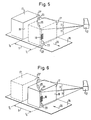
- FIG. 5 is the Direction of movement 26 of the objects again the same as in Fig. 1. Again, the front surface 18 of the Objects 17 are scanned, but the scanning line 23 now perpendicular to the direction of the scan line 23 Fig. 1 stands and therefore the feed direction 25 for the Scanning line 23 takes place in the lateral direction.
- the area 21 ', where the scan begins, is thus in Conveying direction seen on the left front edge of the Items 17 during the end portion 22 'of the scan in the area of the front right edge of the objects located.
- FIG. 6 largely corresponds to that 4, but analogous to FIG. 5 again lateral feed movement of the scanning line 23 by one Initial area 21 'on the rear left edge of the Item 17 to an area 22 'on the rear right Edge of the object 17 takes place.
- the Scans perpendicular to each other according to FIG. 4 and 6 preferably used in combination. It is also possible, depending on the shape and attachment of the barcode 16 several z. B. arrange three scanners at an angle of 60 ° each.
- the alignment of the scan lines 23 to a side edge of the preferably cuboid objects 17 is preferred, but fundamentally other directions are also Scanning line 23, for example possible in the diagonal direction. If two scans are used simultaneously, then in any case, they are perpendicular to each other.
Description
- Fig. 1
- eine schematische perspektivische Ansicht einer Fördervorrichtung mit darauf angeordnetem Gegenstand und einem erfindungsgemäßen Barcodeleser, wobei die vordere Fläche des Gegenstandes abgetastet wird,
- Fig. 2
- eine Seitenansicht eines beim erfindungsgemäßen Barcodeleser verwendeten Scanners in einer rein schematischen, nicht maßstabsgetreuen Darstellung,
- Fig. 3
- eine schematische Ansicht des Scanners nach Linie III-III in Fig. 2,
- Fig. 4
- eine zu Fig. 1 analoge perspektivische Ansicht, wobei jedoch die Förderrichtung umgekehrt ist und die hintere Fläche der Gegenstände abgetastet wird,
- Fig. 5
- eine zu Fig. 1 ähnliche Ansicht, bei der der Scanner so angeordnet ist, daß die Abtastung in einer Richtung senkrecht zur Abtastrichtung nach Fig. 1 liegenden Richtung erfolgt und
- Fig. 6
- eine zu Fig. 4 ähnliche Ansicht mit zur Abtastrichtung nach Fig. 4 senkrechter Richtung der hinteren Fläche von Gegenständen.
Claims (6)
- Verfahren zum Betreiben eines Barcodelesers für auf einem sich zumindest im wesentlichen in einer Richtung (26) bewegenden Gegenstand (17) angebrachte Codierungen (16) mit einem Scanner (12), der einen eine Abtastfläche (18, 19) des Gegenstandes (17) zeilenweise abfahrenden Abtastlichtstrahl (11) erzeugt, eine Lichtempfangsanordnung (13) aufweist, die eine Auswerte- und Steuerelektronik (14) umfaßt, mit der auf der Abtastfläche (18, 19) des Gegenstandes (17) angebrachte, vom Abtastlichtstrahl (11) abgetastete Barcodes (16) erkannt werden können, und welcher außerhalb der Bewegungsbahn (20) des Gegenstandes (17) angeordnet und auf die in Bewegungsrichtung gesehen vordere oder hintere Abtastfläche (18, 19) des Gegenstandes (17) gerichtet ist,
dadurch gekennzeichnet,
daß der Abtastlichtstrahl (11) vor Beginn der Abtastung bei sich auf dem Scanner (12) zu bewegenden Gegenstand (17) auf den dem Scanner (12) am nächsten liegenden Bereich (21) der Abtastfläche (18) und/oder bei von dem Scanner (12) weg bewegenden Gegenstand (17) auf den vom Scanner (12) am weitesten entfernten Bereich (22) der Abtastfläche (19) gerichtet ist, und daß der die zeilenweise Abtastung bewirkende Vorschub (25) der Abtastlinie (22) im wesentlichen senkrecht zur Abtastrichtung (24) mit der Bewegungsgeschwindigkeit des Gegenstandes (17) derart synchronisiert wird, daß der Abstand des Scanners (12) von der Abtastlinie (23) auf der Abtastfläche (18, 19) des Gegenstandes (17) zumindest im wesentlichen gleich bleibt. - Verfahren nach Anspruch 1,
dadurch gekennzeichnet,
daß die Abtastlinie (23) horizontal oder vertikal und ihr Vorschub (25) entsprechend vertikal bzw. horizontal verläuft. - Verfahren nach Anspruch 1 oder 2,
dadurch gekennzeichnet,
daß zwei Scanner (12) verwendet werden, deren Abtastlinien (23) zumindest im wesentlichen senkrecht aufeinander stehen. - Verfahren nach Anspruch 1 oder 2,
dadurch gekennzeichnet,
daß drei oder mehr Scanner (12) verwendet werden, deren Abtastlinien (23) zumindest im wesentlichen unter einem Winkel von 60° bzw. kleineren Winkeln verlaufen. - Barcodeleser für auf einem sich zumindest im wesentlichen in einer Richtung (26) bewegenden Gegenstand (17) angebrachte Codierungen (16) mit einem Scanner (12), der einen eine Abtastfläche (18, 19) des Gegenstandes (17) zeilenweise abfahrenden Abtastlichtstrahl (11) erzeugt, eine Lichtempfangsanordnung (13) aufweist, die eine Auswerte- und Steuerelektronik (14) umfaßt, mit der auf der Abtastfläche (18, 19) des Gegenstandes (17) angebrachte, vom Lichtstrahl (11) abgetastete Barcodes (16) erkannt werden können, und welcher außerhalb der Bewegungsbahn (20) des Gegenstandes (17) angeordnet und auf die in Bewegungsrichtung gesehen vordere oder hintere Abtastfläche (18, 19) des Gegenstandes (17) gerichtet ist, insbesondere zur Ausführung des Verfahrens nach einem der Ansprüche 1 bis 3
dadurch gekennzeichnet,
daß ein Empfangsmittel (27, 28) für den Ort der Abtastfläche (18, 19), an dem die Abtastung beginnen soll, und ein Eingabe- oder Detektionsmittel (29) für die Bewegungsgeschwindigkeit des Gegenstandes (17) vorgesehen und an die Auswerte- und Steuerelektronik (14) angeschlossen sind, und daß die Auswerte- und Steuerelektronik (14) ein Vorschubmittel (30, 31) für die Verschiebung der Abtastlinie (23) derart beaufschlagt, daß der Abstand des Scanners (12) von der Abtastlinie (23) auf der Abtastfläche (18, 19) des Gegenstandes (17) zumindest im wesentlichen gleich bleibt. - Vorrichtung nach Anspruch 5,
dadurch gekennzeichnet,
daß der Scanner (12) ein von einem Lichtstrahl (33) beaufschlagtes, die Abtastbewegung erzeugendes Lichtablenkmittel (32), insbesondere Spiegelrad (32) und ein den vom Lichtablenkmittel (32) reflektierten Lichtstrahl (34) erfassenden, den Vorschub (25) erzeugenden Lichtstrahlschwenkmittel, insbesondere Schwingspiegel (31) erfaßt, der das Licht auf die Abtastfläche (18, 19) richtet und die Abtastlinie (23) an der durch die Auswerte- und Steuerelektronik (14) bestimmten Stelle bildet.
Applications Claiming Priority (2)
| Application Number | Priority Date | Filing Date | Title |
|---|---|---|---|
| DE4336137A DE4336137A1 (de) | 1993-10-22 | 1993-10-22 | Barcodeleser und Verfahren zu seinem Betrieb |
| DE4336137 | 1993-10-22 |
Publications (3)
| Publication Number | Publication Date |
|---|---|
| EP0650134A2 EP0650134A2 (de) | 1995-04-26 |
| EP0650134A3 EP0650134A3 (de) | 1998-08-12 |
| EP0650134B1 true EP0650134B1 (de) | 1999-08-04 |
Family
ID=6500813
Family Applications (1)
| Application Number | Title | Priority Date | Filing Date |
|---|---|---|---|
| EP94115763A Expired - Lifetime EP0650134B1 (de) | 1993-10-22 | 1994-10-06 | Barcodeleser und Verfahren zu seinem Betrieb |
Country Status (4)
| Country | Link |
|---|---|
| US (1) | US5481096A (de) |
| EP (1) | EP0650134B1 (de) |
| JP (1) | JPH07282176A (de) |
| DE (2) | DE4336137A1 (de) |
Families Citing this family (20)
| Publication number | Priority date | Publication date | Assignee | Title |
|---|---|---|---|---|
| JP3072465B2 (ja) * | 1995-10-25 | 2000-07-31 | 富士通株式会社 | バーコード読取装置 |
| IT1289438B1 (it) * | 1996-12-11 | 1998-10-15 | Datalogic Spa | Lettore a scansione di un codice ottico posto su un articolo in movimento e metodo di scansione di detto codice ottico mediante detto |
| DE19700281A1 (de) * | 1997-01-07 | 1998-07-09 | Sick Ag | Optischer Codeleser mit einer optischen Abtastvorrichtung |
| JP3186696B2 (ja) * | 1998-05-28 | 2001-07-11 | 日本電気株式会社 | 光学式記号読取装置 |
| US6405929B1 (en) | 1998-05-29 | 2002-06-18 | Hand Held Products, Inc. | Material detection systems for security documents |
| DE29811486U1 (de) | 1998-06-26 | 1998-10-08 | Sick Ag | Optoelektronischer Sensor |
| DE19840455A1 (de) * | 1998-09-04 | 2000-03-09 | Sick Ag | Verfahren zum Betreiben eines Strichcodelesers |
| US6502750B1 (en) * | 1999-11-24 | 2003-01-07 | Microscan Systems, Inc. | Scanning beam system and method for reading information symbols |
| DE10050368A1 (de) * | 2000-10-11 | 2002-04-18 | Sick Ag | Vorrichtung und Verfahren zur Erkennung von Codes |
| WO2003005274A1 (en) * | 2001-07-03 | 2003-01-16 | Accu-Sort Systems, Inc. | Synchronously sweeping line scan imager |
| DE10222518B4 (de) * | 2002-05-22 | 2004-04-15 | Leuze Electronic Gmbh + Co Kg | Optoelektronische Vorrichtung |
| US6878896B2 (en) * | 2002-07-24 | 2005-04-12 | United Parcel Service Of America, Inc. | Synchronous semi-automatic parallel sorting |
| WO2004079546A2 (en) * | 2003-03-04 | 2004-09-16 | United Parcel Service Of America, Inc. | System for projecting a handling instruction onto a moving item or parcel |
| US7063256B2 (en) * | 2003-03-04 | 2006-06-20 | United Parcel Service Of America | Item tracking and processing systems and methods |
| US7561717B2 (en) * | 2004-07-09 | 2009-07-14 | United Parcel Service Of America, Inc. | System and method for displaying item information |
| US9102055B1 (en) * | 2013-03-15 | 2015-08-11 | Industrial Perception, Inc. | Detection and reconstruction of an environment to facilitate robotic interaction with the environment |
| US8579196B1 (en) * | 2013-03-15 | 2013-11-12 | Ray Lowe | Enhanced utility tag scan method |
| US10471478B2 (en) | 2017-04-28 | 2019-11-12 | United Parcel Service Of America, Inc. | Conveyor belt assembly for identifying an asset sort location and methods of utilizing the same |
| CN111157757A (zh) * | 2019-12-27 | 2020-05-15 | 苏州博田自动化技术有限公司 | 基于视觉的履带速度检测装置及方法 |
| CN114092020B (zh) * | 2022-01-20 | 2022-08-19 | 诚天国际供应链(深圳)有限公司 | 控制系统及基于控制系统的一体式仓储装置 |
Family Cites Families (7)
| Publication number | Priority date | Publication date | Assignee | Title |
|---|---|---|---|---|
| US4064390A (en) * | 1976-04-19 | 1977-12-20 | Spectra-Physics, Inc. | Method and apparatus for reading coded labels |
| SU907564A1 (ru) * | 1980-02-11 | 1982-02-23 | Предприятие П/Я В-8420 | Оптическое устройство распознавани номера движущегос объекта |
| US4483615A (en) * | 1981-12-18 | 1984-11-20 | Owens-Illinois, Inc. | Method and apparatus for detecting checks in glass tubes |
| FR2594982A1 (fr) * | 1986-02-21 | 1987-08-28 | Eram Sarl Manuf Fse Chaussures | Mode de realisation de codes a lecture optique, procede de lecture desdits codes et installation pour la mise en oeuvre du procede |
| DE3728211A1 (de) * | 1987-08-24 | 1989-03-16 | Sick Optik Elektronik Erwin | Scanner zur erfassung von strichcodes auf gegenstaenden |
| US5185822A (en) * | 1988-06-16 | 1993-02-09 | Asahi Kogaku Kogyo K.K. | Focusing structure in an information reading apparatus |
| DE4041336A1 (de) * | 1990-12-21 | 1992-07-02 | Siemens Nixdorf Inf Syst | Verfahren zum lesen einer code-markierung auf gegenstaenden |
-
1993
- 1993-10-22 DE DE4336137A patent/DE4336137A1/de not_active Withdrawn
-
1994
- 1994-10-06 EP EP94115763A patent/EP0650134B1/de not_active Expired - Lifetime
- 1994-10-06 DE DE59408574T patent/DE59408574D1/de not_active Expired - Lifetime
- 1994-10-20 US US08/325,974 patent/US5481096A/en not_active Expired - Lifetime
- 1994-10-24 JP JP6258166A patent/JPH07282176A/ja active Pending
Also Published As
| Publication number | Publication date |
|---|---|
| EP0650134A3 (de) | 1998-08-12 |
| DE59408574D1 (de) | 1999-09-09 |
| JPH07282176A (ja) | 1995-10-27 |
| DE4336137A1 (de) | 1995-04-27 |
| EP0650134A2 (de) | 1995-04-26 |
| US5481096A (en) | 1996-01-02 |
Similar Documents
| Publication | Publication Date | Title |
|---|---|---|
| EP0650134B1 (de) | Barcodeleser und Verfahren zu seinem Betrieb | |
| EP0338376B1 (de) | Verfahren zum optischen Abtasten von Markierungen auf Gegenständen und Vorrichtung zu seiner Durchführung | |
| EP0286080B1 (de) | Vorrichtung zum Steuern des Transportweges von Gegenständen | |
| EP0982083A2 (de) | Lineare Sortereinrichtung | |
| DE2541813A1 (de) | Einrichtung zum ordnen einer anzahl ungeordnet herangefuehrter behaelter zu einer einzigen sich fortbewegenden reihe | |
| EP0896290A2 (de) | Verfahren und Vorrichtung zum Lesen eines aus einer vorgegebenen Anzahl von Codeelementen bestehenden Strichcodes | |
| DE2530886C3 (de) | Vorrichtung zum Ordnen vereinzelter, in entgegengesetzten Richtungen ungeordnet orientierter Gegenstände | |
| DE19840455A1 (de) | Verfahren zum Betreiben eines Strichcodelesers | |
| DE3519312C2 (de) | ||
| DE3706836C2 (de) | ||
| DE69716393T3 (de) | Vorrichtung zum Abtasten eines sich auf einem bewegenden Artikel befindlichen optischen Kodes und Verfahren zum Abtasten eines solchen optischen Kodes mittels dieser Abtastvorrichtung | |
| DE4128733A1 (de) | Transportverfahren fuer in einem strom anfallende stueckgueter, transporteinrichtung hierfuer, verfahren zur positionsbestimmung einer markierung mittels eines derartigen transportverfahrens und anlage hierfuer | |
| EP0653365B1 (de) | Einrichtung für die Kommissionierung von Stückgut | |
| EP0574471A1 (de) | Codierverfahren und codiervorrichtung. | |
| DE4427477C2 (de) | Stauförderer für Transportkisten | |
| DE2200095A1 (de) | Lesevorrichtung fuer optisch erkennbare Zeichen | |
| EP0623835B1 (de) | Verfahren und Anordnung zum Winkeljustieren einer Linienabtastvorrichtung | |
| DE2627277C2 (de) | Verfahren zum geräuscharmen Zusammenführen von Gefäßen | |
| DE4424008C2 (de) | Optoelektronische Vorrichtung zum Erkennen von Marken | |
| DE19508397C2 (de) | Optoelektronische Vorrichtung zum Erkennen von Marken | |
| EP0643362B2 (de) | Vorrichtung zum Lesen von Informationen | |
| DE4313829B4 (de) | Vorrichtung zum Prüfen von Formteilen | |
| DE3310825C2 (de) | ||
| DE4143339A1 (de) | Verfahren zum aufbringen einer codemarkierung auf einer bewegten kunststoffflasche | |
| DE10126876A1 (de) | Verfahren und Vorrichtung zum Sortieren von Stückgütern |
Legal Events
| Date | Code | Title | Description |
|---|---|---|---|
| PUAI | Public reference made under article 153(3) epc to a published international application that has entered the european phase |
Free format text: ORIGINAL CODE: 0009012 |
|
| AK | Designated contracting states |
Kind code of ref document: A2 Designated state(s): DE FR GB IT |
|
| RAP1 | Party data changed (applicant data changed or rights of an application transferred) |
Owner name: SICK AG |
|
| PUAL | Search report despatched |
Free format text: ORIGINAL CODE: 0009013 |
|
| AK | Designated contracting states |
Kind code of ref document: A3 Designated state(s): DE FR GB IT |
|
| 17P | Request for examination filed |
Effective date: 19981012 |
|
| GRAG | Despatch of communication of intention to grant |
Free format text: ORIGINAL CODE: EPIDOS AGRA |
|
| 17Q | First examination report despatched |
Effective date: 19981215 |
|
| GRAG | Despatch of communication of intention to grant |
Free format text: ORIGINAL CODE: EPIDOS AGRA |
|
| GRAH | Despatch of communication of intention to grant a patent |
Free format text: ORIGINAL CODE: EPIDOS IGRA |
|
| GRAH | Despatch of communication of intention to grant a patent |
Free format text: ORIGINAL CODE: EPIDOS IGRA |
|
| GRAA | (expected) grant |
Free format text: ORIGINAL CODE: 0009210 |
|
| ITF | It: translation for a ep patent filed |
Owner name: BARZANO' E ZANARDO MILANO S.P.A. |
|
| AK | Designated contracting states |
Kind code of ref document: B1 Designated state(s): DE FR GB IT |
|
| GBT | Gb: translation of ep patent filed (gb section 77(6)(a)/1977) |
Effective date: 19990805 |
|
| REF | Corresponds to: |
Ref document number: 59408574 Country of ref document: DE Date of ref document: 19990909 |
|
| ET | Fr: translation filed | ||
| PLBE | No opposition filed within time limit |
Free format text: ORIGINAL CODE: 0009261 |
|
| STAA | Information on the status of an ep patent application or granted ep patent |
Free format text: STATUS: NO OPPOSITION FILED WITHIN TIME LIMIT |
|
| 26N | No opposition filed | ||
| PGFP | Annual fee paid to national office [announced via postgrant information from national office to epo] |
Ref country code: GB Payment date: 20000922 Year of fee payment: 7 |
|
| PGFP | Annual fee paid to national office [announced via postgrant information from national office to epo] |
Ref country code: FR Payment date: 20001017 Year of fee payment: 7 |
|
| PG25 | Lapsed in a contracting state [announced via postgrant information from national office to epo] |
Ref country code: GB Free format text: LAPSE BECAUSE OF NON-PAYMENT OF DUE FEES Effective date: 20011006 |
|
| REG | Reference to a national code |
Ref country code: GB Ref legal event code: IF02 |
|
| GBPC | Gb: european patent ceased through non-payment of renewal fee |
Effective date: 20011006 |
|
| PG25 | Lapsed in a contracting state [announced via postgrant information from national office to epo] |
Ref country code: FR Free format text: LAPSE BECAUSE OF NON-PAYMENT OF DUE FEES Effective date: 20020628 |
|
| REG | Reference to a national code |
Ref country code: FR Ref legal event code: ST |
|
| PG25 | Lapsed in a contracting state [announced via postgrant information from national office to epo] |
Ref country code: IT Free format text: LAPSE BECAUSE OF NON-PAYMENT OF DUE FEES;WARNING: LAPSES OF ITALIAN PATENTS WITH EFFECTIVE DATE BEFORE 2007 MAY HAVE OCCURRED AT ANY TIME BEFORE 2007. THE CORRECT EFFECTIVE DATE MAY BE DIFFERENT FROM THE ONE RECORDED. Effective date: 20051006 |
|
| PGFP | Annual fee paid to national office [announced via postgrant information from national office to epo] |
Ref country code: DE Payment date: 20131024 Year of fee payment: 20 |
|
| REG | Reference to a national code |
Ref country code: DE Ref legal event code: R071 Ref document number: 59408574 Country of ref document: DE |
|
| REG | Reference to a national code |
Ref country code: DE Ref legal event code: R071 Ref document number: 59408574 Country of ref document: DE |