EP0650738B1 - Multi-patient fluid dispensing - Google Patents
Multi-patient fluid dispensing Download PDFInfo
- Publication number
- EP0650738B1 EP0650738B1 EP94116908A EP94116908A EP0650738B1 EP 0650738 B1 EP0650738 B1 EP 0650738B1 EP 94116908 A EP94116908 A EP 94116908A EP 94116908 A EP94116908 A EP 94116908A EP 0650738 B1 EP0650738 B1 EP 0650738B1
- Authority
- EP
- European Patent Office
- Prior art keywords
- fluid
- flow
- patient
- delivery system
- sterile
- Prior art date
- Legal status (The legal status is an assumption and is not a legal conclusion. Google has not performed a legal analysis and makes no representation as to the accuracy of the status listed.)
- Expired - Lifetime
Links
- 0 CC*(C)NC Chemical compound CC*(C)NC 0.000 description 1
Images


Classifications
-
- A—HUMAN NECESSITIES
- A61—MEDICAL OR VETERINARY SCIENCE; HYGIENE
- A61M—DEVICES FOR INTRODUCING MEDIA INTO, OR ONTO, THE BODY; DEVICES FOR TRANSDUCING BODY MEDIA OR FOR TAKING MEDIA FROM THE BODY; DEVICES FOR PRODUCING OR ENDING SLEEP OR STUPOR
- A61M5/00—Devices for bringing media into the body in a subcutaneous, intra-vascular or intramuscular way; Accessories therefor, e.g. filling or cleaning devices, arm-rests
- A61M5/14—Infusion devices, e.g. infusing by gravity; Blood infusion; Accessories therefor
- A61M5/168—Means for controlling media flow to the body or for metering media to the body, e.g. drip meters, counters ; Monitoring media flow to the body
- A61M5/16804—Flow controllers
- A61M5/16827—Flow controllers controlling delivery of multiple fluids, e.g. sequencing, mixing or via separate flow-paths
Definitions
- a back flow valve and a sterile filter combination should give sufficient protection. Bacteria cannot penetrate the filter. Viruses and proteins can penetrate the filter but are not active, and so cannot swim upstream. They can only diffuse. The drawbacks to this approach involve the pressure drop through the filter and volume of fluid remaining in the filter. Also, there is no way to verify that the filter is not leaking.
- the present invention deals with additional methods of preventing contamination of the reusable fluid path by the patient being injected.
- the present invention embodies the concept of preventing back flow, by providing no open fluid path through which bacteria can migrate or viruses or pyrogens can diffuse. (If a path is open, the velocity can then be made sufficient to prevent back diffusion). Additionally, turbulence must be avoided since turbulence necessarily involves reverse flows and eddys that can carry material against the flow, unless the flow is high enough to prevent any part of the fluid from having a net upstream velocity vector.
- Prior art document US 4,750,643 discloses a system for delivering sterile fluid to a patient, comprising a source of sterile fluid, a fluid delivery system for directing the sterile fluid from the source to a point of use in conjunction with a patient, wherein a portion of said fluid delivery system including the portion in contact with the patient is disposable and the reminder of the system is reusable, flow interrupting means in each of the disposable portions of said fluid delivery system comprising physical means that cause the flow to exist as discrete quantities and to be discontinuous so that fluid free gaps exist in the delivery system to preclude cross-contamination and per patient hook-ups forming the disposable portions of the fluid delivery system for directing said sterile fluid into a plurality of patients. Further, spring clamps are provided in the reusable portion of the system which selectively close off the corresponding fluid path.
- FIGs. do not show back flow prevention means arranged in each of said per patient hook-ups for allowing flow in a forward direction while preventing flow in the backward direction.
- the patient hook-ups forming the disposable portions of the fluid delivery system for directing the sterile fluid into a plurality of patients are not shown.
- FIG. 1 a source of fluid medium which is contained within a bulk container 10.
- Numeral 11 represents a similar container that is used to hold a supply of diluent, in the event that it is desired to reduce the concentration of the fluid medium contained within source 10.
- a metering pump 12 draws fluid from the supply source 10 at the proper flow rate.
- the second metering pump 13 draws diluent (when desired) from the bulk reservoir 11 within which the supply of diluent is contained.
- a preferred metering pump is a precision peristaltic pump with santoprene tubing.
- a pump wall design similar to that of U.S. Patent No. 5,236,014 would minimize the pulsatile flow characteristics.
- the fluids are removed from containers 10 and 11, they are heated by means of heaters 14 and 15 so that they approximate body temperature. The heating, of course, can decrease the viscosity and make the fluid more comfortable for the patient.
- the fluids Upon leaving the metering pumps 12 and 13, the fluids meet as they are joined and flow through a static mixer 20 that contains helical vanes.
- the company ConProTech makes many sizes and lengths, some with polypropylene vanes and case. These static mixers are designed for mixing fluids with very different viscosities and varying dilution ratios. The exact length and diameter to be used will depend to some degree upon the viscosity of the substances being co-mingled.
- the mixture then flows through a fluid assurance device 22 which many be an ultrasonic detector so that the presence or absence of air in the fluid can be determined. Since these types of devices cannot detect small air bubbles, by being located before a pressurization pump 25, bubbles will be as large as possible. It helps minimize the chance that a broken line or human error can inject air into the patient.
- a supply conduit 26 leads to a rotary switch 27 that can distribute fluid between the individual or "per patient" hookups 30, 31 and 32.
- Each of the individual connections contains what has been diagrammatically shown as a section to mate with a peristaltic apparatus 35. Each per patient disposable tube 36 is placed in a peristaltic apparatus 35 before being connected to the patient.
- the disposable connector tube 36 is disconnected from the patient.
- the rotary valve is turned to seal off the opening and the tube removed from the peristaltic apparatus and the connection to the rotary valve. This portion is then discarded. The next tube should be placed in the peristaltic apparatus.
- the present apparatus includes an electronic control system (ECS) 40 to assure that the needs of the patient are met safely.
- ECS 40 gets information on the contents of the bulk reservoirs 10 and 11.
- the preferred method is to read bar codes indicated by numerals 10' and 11' respectively.
- Another way is to quiz the operator to enter the data each time a bulk reservoir is changed, and then store that information. The operator would read the label on or packaged with the bulk reservoir, and enter the appropriate data. This need only be done when a bulk reservoir is changed.
- a preferred set of information is: 1) the procedure being done, and 2) the patient weight. This way the contrast dose could be optimized for the patient.
- the algorithm would have been previously provided information on milligrams of iodine per kilogram of patient for each procedure when the system was first installed in the hospital. It could display concentration, flow rate and volume for operator verification, if the operator desired.
- An electronic interface 41 is shown which can connect to the hospital information system to get information on the patient, such as weight. Then the operator would only have to input the patient number.
- the electronic interface could also be connected to the imaging equipment.
- a hard copy printer may be optionally part of the user interface, receiving data from the ECS. This can print a record of the actual injection for insertion into the patient records.
- the output may be alphanumeric or be a graphical representation of the injection.
- the operation of delivering fluid to the patient can be started by the operator with a start switch on the contrast delivery system, or from the console of the scanner. There would need to be an arming procedure similar to that of present injectors to help assure patient safety.
- Another form of waste is using contrast to prime the fluid path which is disposed of with each patient, especially if the concentration has not yet been decided upon.
- the flush or diluent fluid is much cheaper than the contrast and of lower viscosity, so it can be used to prime the line and make sure that all air has been removed from the path to the patient.
- FIGS. 2 and 3 an alternative would be to make the peristaltic mechanism be fixed with the tubing, rather than separate as shown in FIG. 1. It would be disposable, but, it could be a very simple disposable with four wheels on a cross and a band which held the tubing for one or more turns. (It could be less than one turn, but one or more is preferred to equalize the lateral forces.)
- This type of construction is shown in FIGS. 4 and 3 with numeral 50 indicating the wheels mounted on cross 51 and in contact with supply tubing 52.
- FIG. 4 shows an even simpler arrangement where the wheels form a planetary gear set 60, with the inner gear free to rotate. In this embodiment, it might be easier to have the ratchet mechanism on the band as shown at 61 in FIG. 3.
- This whole assembly does not need to be more than 25.4 mm (1") across. While the peristaltic pump never has an open fluid path, turbulence can move material from the wall to the wall farther upstream. Thus, it is desirable, but not essential, that the tubing diameter be chosen to preserve laminar flow. Since the flow ranges differ by modality, the Reynolds number calculation, familiar to fluid mechanics, will need to be used to make this determination.
- the peristaltic mechanism could be used as a flow sensor. It could be coupled to a shaft on the durable equipment or an optical sensor could detect when the gears pass. Another use of the peristaltic flow sensor is as a mechanical stop. Peristaltic flow sensor could be placed on the durable equipment in such a way that the ECS 40 read the number of revolutions and stop its rotation when the appropriate volume was reached. Because the peristaltic flow sensor has some friction, it also prevents flow through caused by gravity when the system is off. The integral disposable peristaltic mechanism would limit dripping when the "per patient” disposable is removed. This "per patient” disposable peristaltic pump would also be a convenient pumping means for other low pressure IV fluid injections.
- any type of peristaltic motion is acceptable.
- a linear peristaltic mechanism would work. Two lines may be run in parallel through out of phase peristaltic mechanisms and their outputs combined to significantly decrease pulsations.
- a peristaltic mechanism while effective is not sufficient to prevent cross-contamination, if turned backwards, either by operator action or by back pressure, for example.
- a back flow prevention means in the line, or preferably in the peristaltic mechanism itself.
- FIG. 7 shows another means of dividing the fluid flow into discrete packets to prevent cross-contamination.
- This is a variation on the peristaltic idea, where the fluid path splits into two parts.
- fluid is flowing into chamber 1, it's outlet is blocked so the chamber expands and drives the pressure plate against chamber 2.
- This drives fluid out of chamber 2 and on to the patient.
- the inlet and outlet valves switch position, allowing chamber 2 to fill and chamber 1 to empty. This allows continuous fluid flow but never permits a continuously open fluid path to exist.
- the pressure plate upon reaching its end of travel mechanically triggers the inlet valves, and that there be a mechanical linkage between the valves so that they can not both simultaneously open to the same chamber.
- These controlling strategies could also be performed by the ECS, with redundancy and verification of valve positions. It is possible to extend this concept to using three or more chambers, to get a more even flow.
- FIG. 9 shows another implementation of packetizing of the fluid flow. In this embodiment it is accomplished via air separation rather than via an intervening solid. After the fluids are mixed, they flow through a back flow valve. The fluid then flows through a "y" where it is mixed with packets of air. The air packets separate fluid packets, preventing back diffusion or migration of contaminants if the flow slows or stops. The wall material and diameter of the tubing is chosen so that the air packets are stable. During operation, fluid and air flow down the line to the air separating chamber. Here air separates itself from the fluid and moves upward through a filter, returning to be used again. Fluid flows on to the pressurizing pump.
- the pulsatile air pump could be a peristaltic pump, possibly operating out of phase with the fluid metering pumps so that air is injected when liquid flow is minimum from the metering pumps.
- the liquid flows through a fluid assurance device, is pressurized by the pressurizing pump and flows into the patient.
- the ECS will stop the pumping if the fluid assurance detector detects any air in the line to the pressurizing pump. All of the tubing down stream from the "per patient" connector is disposed of after each patient. If the flow from the metering pumps is sufficiently pulsatile, it may not be necessary to have the air pump.
- the momentum of flowing fluid can be sufficient to entrain packets of air between packets of fluid.
- FIGS. 5a and 5b there is provided a spring loaded conical section 65 which is contained in at conical housing 66. Since this arrangement has an open fluid path when fluid is flowing, it is desireable to maintain laminar flow. This configuration has the advantage that the width of the flow path increases to accommodate increased flow.
- the frontal area at cross section (A), the slope of the cylinder walls and the strength of the spring can be chosen to assure that the Reynolds number stays in the laminar flow region over the designed operating range.
- the pressure drop and speed of flow need to be high enough that no material can diffuse against the flow.
- the conical surfaces need to be chosen so that they mate over a wide length. A single line of sealing is not desireable. Multiple lines of sealing are better but not the best.
- redundancy is achieved by having several conical blockers in series, or conical blocker in series with a peristaltic blocker. These could be combined with sterile filters or with air gaps as set forth below. While any one can be sufficient alone, the combinations may be needed to satisfy the perceptions of the patients or hospital personnel.
- this embodiment uses a similar principal but it has an air gap as the blocking means to preclude cross-contamination. Bacteria and viruses which are in a fluid cannot become airborne unless the fluid is dispersed into the air.
- drip chambers in which fluid drips through air. They are used with most IV injections. These drip chambers are designed for flow measuring. They are part of single use disposable devices and so have no relation to cross-contamination prevention.
- FIG. 8 disposable burettes which can be filled from a sterile container and fluid in them then subsequently sterilely dispensed. If filled once and then dispensed into a patient, the bulk source is protected from back flow of contaminants from the patient. But if any attempt is made to have fluid flow into the burette while connected to the patient and the bulk source, they do not provide a cross-contamination barrier. This is because fluid flowing into the burette falls some distance and can cause a splash which has a possibility of carrying fluid from the bottom of the burette to the inlet nozzle. When fluid is being let out, low flow rates allow back migration of bacteria or back diffusion of virus or pyrogens. Subsequent splashing can bring these contaminants to the inlet and contaminate the remainder of the fluid path. Thus, in the embodiments below, great care is taken to eliminate potential splashing which can carry fluid across the air gap.
- An embodiment for the class of blocking means forming a break in the fluid stream uses a collapsible bag 75, as shown in FIG. 6, or other large container.
- a collapsible bag 75 When the fluid injector is armed, a significant fraction of the fluid requested for the injection is pumped into the collapsible bag. This fraction could be operator controlled and depend upon the confidence the operator had that the full amount of fluid will be used.
- the start switch When the operator depresses the start switch, the injection starts.
- the metering pumps continue filling the bag at a slower rate than the pressurizing pump is withdrawing it, with the fill rate chosen so that filling is completed a few seconds before the injection is completed.
- the benefit of this over the funnel is the ability to start the injection and change flow rates instantaneously.
- the bag may be less costly than the funnel although neither part sees high pressures.
- a final benefit may be user perception. They may have more confidence in a device which fills an intermediate bag than in a system where there are just a few milliliters of fluid in a funnel, even though electronics and mechanics make them equally reliable.
- the bag needs to be made from hydrophobic material such as polypropylene so that no continuous stream of fluid remains after flow is stopped.
- the flow entering the bag needs to be slowed by choice of inlet diameter and tangential path so that it adheres to the wall and no splashing occurs.
Description
- In copending application EP 94 116 909.6 of even date herewith and assigned to the same Assignee as the present invention, discussion was undertaken with regard to the problems arising from the potential cross-contamination that can occur with a multi-patient fluid dispensing system. One facet of the system provided involves prevention of contamination of the multi-use segment of the fluid path during the time the system is connected to the patient. The disclosed system utilizes a back flow preventing valve and a sterile filter.
- A back flow valve and a sterile filter combination should give sufficient protection. Bacteria cannot penetrate the filter. Viruses and proteins can penetrate the filter but are not active, and so cannot swim upstream. They can only diffuse. The drawbacks to this approach involve the pressure drop through the filter and volume of fluid remaining in the filter. Also, there is no way to verify that the filter is not leaking.
- The present invention deals with additional methods of preventing contamination of the reusable fluid path by the patient being injected. To achieve the improved methods of preventing contamination, the present invention embodies the concept of preventing back flow, by providing no open fluid path through which bacteria can migrate or viruses or pyrogens can diffuse. (If a path is open, the velocity can then be made sufficient to prevent back diffusion). Additionally, turbulence must be avoided since turbulence necessarily involves reverse flows and eddys that can carry material against the flow, unless the flow is high enough to prevent any part of the fluid from having a net upstream velocity vector.
- Prior art document US 4,750,643 discloses a system for delivering sterile fluid to a patient, comprising a source of sterile fluid, a fluid delivery system for directing the sterile fluid from the source to a point of use in conjunction with a patient, wherein a portion of said fluid delivery system including the portion in contact with the patient is disposable and the reminder of the system is reusable, flow interrupting means in each of the disposable portions of said fluid delivery system comprising physical means that cause the flow to exist as discrete quantities and to be discontinuous so that fluid free gaps exist in the delivery system to preclude cross-contamination and per patient hook-ups forming the disposable portions of the fluid delivery system for directing said sterile fluid into a plurality of patients. Further, spring clamps are provided in the reusable portion of the system which selectively close off the corresponding fluid path.
- Means of preventing contamination of the fluid path by contaminants other than the patient being injected are presented in copending application EP 94 116 909.6. Any of the concepts presented there may be matched with any of the embodiments presented here. The relevant feature is the "per patient" connection.
- It is a principal object of this invention to provide an improved apparatus for injecting a fluid medium into a plurality of patients while minimizing the chance of cross-contamination.
- It is another object of this invention to provide an apparatus for injecting fluid mediums into patients in which there is no continuous stream of fluid existing between the source of the fluid and the patient.
- It is another object of this invention to provide an apparatus in which a peristaltic apparatus is present which precludes the reverse flow of substances from the patient towards the origin of the fluid to be injected.
- These objects are solved by a system for delivering sterile fluid to a patient in accordance to
claims 1 and 5. Further embodiments of this invention are the subject matter ofsubclaims 2 through 4 and 6 and 7. - Other objects and advantages of this invention will be in part obvious and in part explained by reference to the accompanying specification and drawings in which:
-
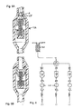
- FIG. 1 diagrammatically shows an apparatus and a system for injecting a fluid medium directly into a patient which minimizes the chance of patient-to-patient cross-contamination;
- FIG. 2 is a form of peristaltic control apparatus that can be used in the cross-contamination preventing system of FIG. 1;
- FIG. 3 is a front perspective of the apparatus of FIG. 2;
- FIG. 4 is another diagram showing another type of peristaltic apparatus for use in the present invention;
- FIGs. 5a and 5b are diagrammatic illustrations of an apparatus in which there is a biased element to preclude reverse flow of fluid from the patient towards the source of medical fluid;
- FIG. 6 is a diagrammatic showing of another type of apparatus having discontinuous flow and a plurality of patient connections;
- FIG. 7 is a diagrammatic showing of a packeted flow means;
- FIG. 8 is a diagrammatic showing of a disposable burette system; and
- FIG. 9 is a diagrammatic showing another system for packeting flow means.
-
- It is to be noted that the FIGs. do not show back flow prevention means arranged in each of said per patient hook-ups for allowing flow in a forward direction while preventing flow in the backward direction. In addition, in FIG. 9 the patient hook-ups forming the disposable portions of the fluid delivery system for directing the sterile fluid into a plurality of patients are not shown.
- To better understand the present invention, reference is made to the drawings, and specifically to FIG. 1 there is provided a source of fluid medium which is contained within a
bulk container 10.Numeral 11 represents a similar container that is used to hold a supply of diluent, in the event that it is desired to reduce the concentration of the fluid medium contained withinsource 10. Ametering pump 12 draws fluid from thesupply source 10 at the proper flow rate. Thesecond metering pump 13 draws diluent (when desired) from thebulk reservoir 11 within which the supply of diluent is contained. A preferred metering pump is a precision peristaltic pump with santoprene tubing. A pump wall design similar to that of U.S. Patent No. 5,236,014 would minimize the pulsatile flow characteristics. As the fluids are removed fromcontainers heaters metering pumps fluid assurance device 22 which many be an ultrasonic detector so that the presence or absence of air in the fluid can be determined. Since these types of devices cannot detect small air bubbles, by being located before apressurization pump 25, bubbles will be as large as possible. It helps minimize the chance that a broken line or human error can inject air into the patient. From pressurizingpump 25, asupply conduit 26 leads to arotary switch 27 that can distribute fluid between the individual or "per patient"hookups disposable tube 36 is placed in a peristaltic apparatus 35 before being connected to the patient. Then it is connected to the patient and the injection is completed. Thedisposable connector tube 36 is disconnected from the patient. The rotary valve is turned to seal off the opening and the tube removed from the peristaltic apparatus and the connection to the rotary valve. This portion is then discarded. The next tube should be placed in the peristaltic apparatus. - This is a good strategy but it requires operator vigilance to make sure that the line is in the peristaltic device before being connected to the patient and that the rotary valve is moved before the line is removed from the peristaltic device. Interlocks and intermediate all/off positions on the rotary switch could be provided. The rotary valve could have a) "no connection" position between each connection position. The interlocks could function such that the rotary valve cannot be moved to access an output line until the line is in the peristaltic device, and another interlock could require that the rotary valve be turned to the intermediate off before the tubing can be removed from the peristaltic pump.
- The present apparatus includes an electronic control system (ECS) 40 to assure that the needs of the patient are met safely. ECS 40 gets information on the contents of the
bulk reservoirs - With each injection, the operator needs to tell the system what to do. The data most similar to present practice is: 1) the concentration desired, 2) the flow rate, and 3) the total volume to be delivered. Present practice also includes multiple phases with various flow rates during each phase. This system would allow various contrast concentrations during each flow rate as well.
- However, given the capabilities of this system, a preferred set of information is: 1) the procedure being done, and 2) the patient weight. This way the contrast dose could be optimized for the patient. The algorithm would have been previously provided information on milligrams of iodine per kilogram of patient for each procedure when the system was first installed in the hospital. It could display concentration, flow rate and volume for operator verification, if the operator desired. An electronic interface 41 is shown which can connect to the hospital information system to get information on the patient, such as weight. Then the operator would only have to input the patient number. The electronic interface could also be connected to the imaging equipment. It could send or receive information so that, for instance, the operator only need to program the CT scanner with number of slices and body section, and this would be transmitted to the contrast delivery system to be used in determining flow rates and delays. The electronic interface would also be used to let the scanner trigger the contrast delivery system or vice versa, after the appropriate delays. A hard copy printer may be optionally part of the user interface, receiving data from the ECS. This can print a record of the actual injection for insertion into the patient records. The output may be alphanumeric or be a graphical representation of the injection.
- The operation of delivering fluid to the patient can be started by the operator with a start switch on the contrast delivery system, or from the console of the scanner. There would need to be an arming procedure similar to that of present injectors to help assure patient safety.
- In CT, usually only one injection is given, sometimes with pauses and changes in flow rates. As the end of the injection is reached, contrast can be conserved if the contrast flow is stopped and the diluent flow continued so the "bolus" of diluted contrast is flushed out of the tubing and into the patient. In angiography, several injections may be used. It is necessary to flush only after the last injection, although no harm, except injecting a little extra fluid, occurs if the flush follows each injection.
- Another form of waste is using contrast to prime the fluid path which is disposed of with each patient, especially if the concentration has not yet been decided upon. The flush or diluent fluid is much cheaper than the contrast and of lower viscosity, so it can be used to prime the line and make sure that all air has been removed from the path to the patient.
- Referring to FIGS. 2 and 3 an alternative would be to make the peristaltic mechanism be fixed with the tubing, rather than separate as shown in FIG. 1. It would be disposable, but, it could be a very simple disposable with four wheels on a cross and a band which held the tubing for one or more turns. (It could be less than one turn, but one or more is preferred to equalize the lateral forces.) This type of construction is shown in FIGS. 4 and 3 with
numeral 50 indicating the wheels mounted on cross 51 and in contact withsupply tubing 52. FIG. 4 shows an even simpler arrangement where the wheels form a planetary gear set 60, with the inner gear free to rotate. In this embodiment, it might be easier to have the ratchet mechanism on the band as shown at 61 in FIG. 3. This whole assembly does not need to be more than 25.4 mm (1") across. While the peristaltic pump never has an open fluid path, turbulence can move material from the wall to the wall farther upstream. Thus, it is desirable, but not essential, that the tubing diameter be chosen to preserve laminar flow. Since the flow ranges differ by modality, the Reynolds number calculation, familiar to fluid mechanics, will need to be used to make this determination. - The peristaltic mechanism could be used as a flow sensor. It could be coupled to a shaft on the durable equipment or an optical sensor could detect when the gears pass. Another use of the peristaltic flow sensor is as a mechanical stop. Peristaltic flow sensor could be placed on the durable equipment in such a way that the ECS 40 read the number of revolutions and stop its rotation when the appropriate volume was reached. Because the peristaltic flow sensor has some friction, it also prevents flow through caused by gravity when the system is off. The integral disposable peristaltic mechanism would limit dripping when the "per patient" disposable is removed. This "per patient" disposable peristaltic pump would also be a convenient pumping means for other low pressure IV fluid injections.
- In all the peristaltic mechanisms above, any type of peristaltic motion is acceptable. A linear peristaltic mechanism would work. Two lines may be run in parallel through out of phase peristaltic mechanisms and their outputs combined to significantly decrease pulsations.
- Also, it is important to note that a peristaltic mechanism while effective is not sufficient to prevent cross-contamination, if turned backwards, either by operator action or by back pressure, for example. There has to be a back flow prevention means in the line, or preferably in the peristaltic mechanism itself.
- FIG. 7 shows another means of dividing the fluid flow into discrete packets to prevent cross-contamination. This is a variation on the peristaltic idea, where the fluid path splits into two parts. In this picture, fluid is flowing into
chamber 1, it's outlet is blocked so the chamber expands and drives the pressure plate againstchamber 2. This drives fluid out ofchamber 2 and on to the patient. When the pressure plate reaches the maximum designed travel, the inlet and outlet valves switch position, allowingchamber 2 to fill andchamber 1 to empty. This allows continuous fluid flow but never permits a continuously open fluid path to exist. It is preferred that the pressure plate upon reaching its end of travel mechanically triggers the inlet valves, and that there be a mechanical linkage between the valves so that they can not both simultaneously open to the same chamber. These controlling strategies could also be performed by the ECS, with redundancy and verification of valve positions. It is possible to extend this concept to using three or more chambers, to get a more even flow. - FIG. 9 shows another implementation of packetizing of the fluid flow. In this embodiment it is accomplished via air separation rather than via an intervening solid. After the fluids are mixed, they flow through a back flow valve. The fluid then flows through a "y" where it is mixed with packets of air. The air packets separate fluid packets, preventing back diffusion or migration of contaminants if the flow slows or stops. The wall material and diameter of the tubing is chosen so that the air packets are stable. During operation, fluid and air flow down the line to the air separating chamber. Here air separates itself from the fluid and moves upward through a filter, returning to be used again. Fluid flows on to the pressurizing pump. The pulsatile air pump could be a peristaltic pump, possibly operating out of phase with the fluid metering pumps so that air is injected when liquid flow is minimum from the metering pumps. After the air is separated from the liquid, the liquid flows through a fluid assurance device, is pressurized by the pressurizing pump and flows into the patient. The ECS will stop the pumping if the fluid assurance detector detects any air in the line to the pressurizing pump. All of the tubing down stream from the "per patient" connector is disposed of after each patient. If the flow from the metering pumps is sufficiently pulsatile, it may not be necessary to have the air pump. The momentum of flowing fluid can be sufficient to entrain packets of air between packets of fluid.
- In another embodiment, see specifically FIGS. 5a and 5b, there is provided a spring loaded conical section 65 which is contained in at conical housing 66. Since this arrangement has an open fluid path when fluid is flowing, it is desireable to maintain laminar flow. This configuration has the advantage that the width of the flow path increases to accommodate increased flow. The frontal area at cross section (A), the slope of the cylinder walls and the strength of the spring can be chosen to assure that the Reynolds number stays in the laminar flow region over the designed operating range. The pressure drop and speed of flow need to be high enough that no material can diffuse against the flow. The conical surfaces need to be chosen so that they mate over a wide length. A single line of sealing is not desireable. Multiple lines of sealing are better but not the best.
- It may be that redundancy is achieved by having several conical blockers in series, or conical blocker in series with a peristaltic blocker. These could be combined with sterile filters or with air gaps as set forth below. While any one can be sufficient alone, the combinations may be needed to satisfy the perceptions of the patients or hospital personnel.
- Referring to FIG. 6 of the drawings, this embodiment uses a similar principal but it has an air gap as the blocking means to preclude cross-contamination. Bacteria and viruses which are in a fluid cannot become airborne unless the fluid is dispersed into the air.
- Present hospital practice uses drip chambers, in which fluid drips through air. They are used with most IV injections. These drip chambers are designed for flow measuring. They are part of single use disposable devices and so have no relation to cross-contamination prevention.
- Present art also included disposable burettes (FIG. 8) which can be filled from a sterile container and fluid in them then subsequently sterilely dispensed. If filled once and then dispensed into a patient, the bulk source is protected from back flow of contaminants from the patient. But if any attempt is made to have fluid flow into the burette while connected to the patient and the bulk source, they do not provide a cross-contamination barrier. This is because fluid flowing into the burette falls some distance and can cause a splash which has a possibility of carrying fluid from the bottom of the burette to the inlet nozzle. When fluid is being let out, low flow rates allow back migration of bacteria or back diffusion of virus or pyrogens. Subsequent splashing can bring these contaminants to the inlet and contaminate the remainder of the fluid path.
Thus, in the embodiments below, great care is taken to eliminate potential splashing which can carry fluid across the air gap. - An embodiment for the class of blocking means forming a break in the fluid stream uses a collapsible bag 75, as shown in FIG. 6, or other large container. When the fluid injector is armed, a significant fraction of the fluid requested for the injection is pumped into the collapsible bag. This fraction could be operator controlled and depend upon the confidence the operator had that the full amount of fluid will be used. When the operator depresses the start switch, the injection starts. The metering pumps continue filling the bag at a slower rate than the pressurizing pump is withdrawing it, with the fill rate chosen so that filling is completed a few seconds before the injection is completed. The benefit of this over the funnel is the ability to start the injection and change flow rates instantaneously. The bag may be less costly than the funnel although neither part sees high pressures. A final benefit may be user perception. They may have more confidence in a device which fills an intermediate bag than in a system where there are just a few milliliters of fluid in a funnel, even though electronics and mechanics make them equally reliable.
- The bag needs to be made from hydrophobic material such as polypropylene so that no continuous stream of fluid remains after flow is stopped. The flow entering the bag needs to be slowed by choice of inlet diameter and tangential path so that it adheres to the wall and no splashing occurs.
- While not ideal, it is possible to eliminate the static mixer by filling the bag, providing ultrasonic agitation and then pumping the mixture out. This is not as desirable because concentration cannot be changed during delivery.
- By properly sizing the bag, the need for a back flow preventer is eliminated. If the total volume of the fluid path down stream from the bag is less than the volume required to fill the bag, then back flow can never breach the air gap. If the bag volume is less than the down stream fluid path volume, then a back flow valve is needed.
- It is also important that the bag be held in the proper upright position during use, since gravity is being used to assure that air surround the inlet port.
Claims (7)
- A system for delivering sterile fluid to a patient, comprising:a) a source (10, 11) of sterile fluidb) a fluid delivery system for directing the sterile fluid from the source (10, 11) to a point of use in conjunction with a patient, wherein a portion of said fluid delivery system including the portion in contact with the patient is disposable and the remainder of the system is reusablec) flow interrupting means in each of the disposable portions of said fluid delivery system comprising physical means that cause the flow to exist as discrete quantities and to be discontinuous so that fluid free gaps exist in the delivery system to preclude cross-contamination,d) per patient hook-ups (30, 31, 32) forming the disposable portions of the fluid delivery system for directing said sterile fluid into a plurality of patients ande) backflow prevention means arranged in each of said per patient hook-ups (30, 31, 32) for allowing flow in a forward direction while preventing flow in a backward direction.
- A system as defined in claim 1, wherein said flow interrupting means comprises a peristaltic flow mechanism (35).
- A system as defined in claim 1 or 2, wherein said flow interrupting means comprises a valve (66) having a fluid flow control means (65) that is positively biased towards a flow interrupting position.
- A system as defined in claim 3, wherein said biased fluid flow control means (65) is shaped to create a laminar fluid flow in fluid passing therethrough.
- A system for delivering sterile fluid to a patient, comprising:a) a source (10, 11) of sterile fluid,b) a fluid delivery system for directing the sterile fluid from the source (10, 11) to a point of use in conjunction with a patient, wherein a portion of said fluid delivery system including the portion in contact with the patient is disposable and the remainder of the system is reusable,c) flow interrupting means in each of the disposable portions of said fluid delivery system comprising a hydrophobic surface over which the fluid is caused to flow and which prevents a string of fluid from remaining after flow is stopped to preclude cross-contamination, wherein said flow interrupting means is a collapsible bag (75) made from a hydrophobic material,d) per patient hook-ups (30, 31, 32) forming the disposable portions of the fluid delivery system for directing said sterile fluid into a plurality of patients ande) backflow prevention means arranged in each of said per patient hook-ups (30, 31, 32) for allowing flow in a forward direction while preventing flow in a backward direction.
- A system as defined in any one of claims 1 - 5, wherein valve means (27) is provided to selectively operate each of said per patient hook-ups (30, 31, 32).
- A system as defined in claim 5 or 6, wherein said hydrophobic material is polypropylene.
Applications Claiming Priority (2)
| Application Number | Priority Date | Filing Date | Title |
|---|---|---|---|
| US14446093A | 1993-10-28 | 1993-10-28 | |
| US144460 | 1993-10-28 |
Publications (2)
| Publication Number | Publication Date |
|---|---|
| EP0650738A1 EP0650738A1 (en) | 1995-05-03 |
| EP0650738B1 true EP0650738B1 (en) | 2003-05-02 |
Family
ID=22508691
Family Applications (1)
| Application Number | Title | Priority Date | Filing Date |
|---|---|---|---|
| EP94116908A Expired - Lifetime EP0650738B1 (en) | 1993-10-28 | 1994-10-26 | Multi-patient fluid dispensing |
Country Status (3)
| Country | Link |
|---|---|
| US (4) | US5843037A (en) |
| EP (1) | EP0650738B1 (en) |
| DE (1) | DE69432582T2 (en) |
Families Citing this family (140)
| Publication number | Priority date | Publication date | Assignee | Title |
|---|---|---|---|---|
| US5450847A (en) * | 1991-04-22 | 1995-09-19 | Schering Aktiengesellschaft | Process for making doses formulation of contrast media from concentrate |
| DE1258262T1 (en) * | 1993-10-28 | 2003-04-10 | Medrad Inc | Contrast delivery system |
| EP0650738B1 (en) * | 1993-10-28 | 2003-05-02 | Medrad, Inc. | Multi-patient fluid dispensing |
| US5840026A (en) * | 1994-09-21 | 1998-11-24 | Medrad, Inc. | Patient specific dosing contrast delivery systems and methods |
| US5540668A (en) * | 1995-01-20 | 1996-07-30 | Wilson, Jr.; Roland B. | Anti-cross contamination valve and fluid delivery systems using same |
| US8082018B2 (en) * | 1995-04-20 | 2011-12-20 | Acist Medical Systems, Inc. | System and method for multiple injection procedures on heart vessels |
| US6656157B1 (en) * | 1995-04-20 | 2003-12-02 | Acist Medical Systems, Inc. | Infinitely refillable syringe |
| US7267666B1 (en) * | 1995-04-20 | 2007-09-11 | Acist Medical Systems, Inc. | Angiographic injector system with multiple processor redundancy |
| US20030028145A1 (en) * | 1995-04-20 | 2003-02-06 | Duchon Douglas J. | Angiographic injector system with multiple processor redundancy |
| US6099502A (en) * | 1995-04-20 | 2000-08-08 | Acist Medical Systems, Inc. | Dual port syringe |
| EP1230902A1 (en) | 1996-11-15 | 2002-08-14 | Advanced Bio Surfaces, Inc. | Biomaterial system for in situ tissue repair |
| FR2757069A1 (en) * | 1996-12-18 | 1998-06-19 | Debiotech Sa | MEDICAL LIQUID INJECTION DEVICE |
| ATE420682T1 (en) * | 1997-11-07 | 2009-01-15 | Acist Medical Sys Inc | ANGIOGRAPHY SYRINGE WITH MULTIPLE REDUNDANT PROCESSORS |
| US6317623B1 (en) | 1999-03-12 | 2001-11-13 | Medrad, Inc. | Apparatus and method for controlling contrast enhanced imaging procedures |
| JP2002541563A (en) * | 1999-04-01 | 2002-12-03 | アシスト メディカル システムズ, インコーポレイテッド | System and method for integrated medical information management and medical device control |
| US6264601B1 (en) * | 1999-04-02 | 2001-07-24 | World Heart Corporation | Implantable ventricular assist device |
| US6355024B1 (en) | 1999-07-14 | 2002-03-12 | Mallinckrodt Inc. | Medical fluid delivery system |
| US6468261B1 (en) | 1999-07-14 | 2002-10-22 | Mallinckrodt Inc. | Medical fluid delivery system |
| ES2162573B1 (en) * | 1999-08-04 | 2002-08-01 | Probitas Pharma Sa | ANGIOGRAPHY DEVICE FOR CO2 INJECTION. |
| WO2001013785A2 (en) * | 1999-08-20 | 2001-03-01 | Acist Medical Systems, Inc. | Apparatus and method of detecting fluid |
| US6495366B1 (en) | 1999-09-03 | 2002-12-17 | Therakos, Inc. | Uninterrupted flow pump apparatus and method |
| US8722422B2 (en) | 1999-09-03 | 2014-05-13 | Therakos, Inc. | Uninterrupted flow pump apparatus and method |
| US6876991B1 (en) | 1999-11-08 | 2005-04-05 | Collaborative Decision Platforms, Llc. | System, method and computer program product for a collaborative decision platform |
| SE523272C2 (en) * | 1999-11-15 | 2004-04-06 | Aneo Ab | System for intravenous anesthesia for the control of a drug delivery to a patient |
| US6669679B1 (en) | 2000-01-07 | 2003-12-30 | Acist Medical Systems, Inc. | Anti-recoil catheter |
| US7204821B1 (en) | 2000-01-31 | 2007-04-17 | Ethicon, Inc. | Surgical fluid management system with suction control |
| US6595957B1 (en) | 2000-01-31 | 2003-07-22 | Ethicon, Inc. | Surgical fluid management system with a dampening chamber |
| US6396583B1 (en) * | 2000-01-31 | 2002-05-28 | Ethicon, Inc. | Optical fluid sensor |
| US6626862B1 (en) * | 2000-04-04 | 2003-09-30 | Acist Medical Systems, Inc. | Fluid management and component detection system |
| US6471674B1 (en) | 2000-04-21 | 2002-10-29 | Medrad, Inc. | Fluid delivery systems, injector systems and methods of fluid delivery |
| US6793643B1 (en) | 2000-04-21 | 2004-09-21 | Therakos, Inc. | Low extracorporeal volume treatment system |
| US6673048B1 (en) | 2000-05-24 | 2004-01-06 | Acist Medical Systems, Inc. | Pressure sleeve assembly |
| US6752789B2 (en) * | 2000-07-20 | 2004-06-22 | Acist Medical Systems, Inc. | Syringe plunger locking mechanism |
| US8565860B2 (en) | 2000-08-21 | 2013-10-22 | Biosensors International Group, Ltd. | Radioactive emission detector equipped with a position tracking system |
| US8489176B1 (en) | 2000-08-21 | 2013-07-16 | Spectrum Dynamics Llc | Radioactive emission detector equipped with a position tracking system and utilization thereof with medical systems and in medical procedures |
| US8909325B2 (en) | 2000-08-21 | 2014-12-09 | Biosensors International Group, Ltd. | Radioactive emission detector equipped with a position tracking system and utilization thereof with medical systems and in medical procedures |
| US7094216B2 (en) | 2000-10-18 | 2006-08-22 | Medrad, Inc. | Injection system having a pressure isolation mechanism and/or a handheld controller |
| DE50111352D1 (en) * | 2000-12-12 | 2006-12-14 | Jakob Boesherz | A medical fluid pumping device and medical treatment device for delivering a fluid to the human or animal body |
| US7018363B2 (en) * | 2001-01-18 | 2006-03-28 | Medrad, Inc. | Encoding and sensing of syringe information |
| WO2002064194A1 (en) * | 2001-02-14 | 2002-08-22 | Acist Medical Systems, Inc. | Fluid injector system |
| US20020143294A1 (en) * | 2001-02-14 | 2002-10-03 | Duchon Douglas J. | Catheter fluid control system |
| US6969865B2 (en) * | 2001-02-15 | 2005-11-29 | Acist Medical Systems, Inc. | Systems and methods for detection and measurement of elements in a medium |
| US7308300B2 (en) * | 2001-05-30 | 2007-12-11 | Acist Medical Systems, Inc. | Medical injection system |
| WO2003050491A2 (en) * | 2001-12-07 | 2003-06-19 | Acist Medical Systems, Inc. | Low pressure measurement devices in high pressure environments |
| WO2004069153A2 (en) * | 2003-01-27 | 2004-08-19 | Medrad, Inc. | Apparatus, system and method for generating bubbles on demand |
| US6880808B2 (en) | 2002-05-03 | 2005-04-19 | Acist Medical Systems, Inc. | Gamma-stable high pressure stopcock |
| US7240882B2 (en) * | 2002-11-25 | 2007-07-10 | Medrad, Inc. | Medical container loading system and method for use with fluid containers, syringes and medical injectors |
| WO2004091688A2 (en) | 2003-04-08 | 2004-10-28 | Medrad, Inc. | Fluid delivery systems, devices and methods for delivery of hazardous fluids |
| US7461968B2 (en) * | 2003-10-30 | 2008-12-09 | Deka Products Limited Partnership | System, device, and method for mixing liquids |
| CA2490970A1 (en) * | 2003-12-23 | 2005-06-23 | Douglas R. Dykaar | Apparatus and method for emitting light to a desired target location |
| US7968851B2 (en) | 2004-01-13 | 2011-06-28 | Spectrum Dynamics Llc | Dynamic spect camera |
| WO2005067383A2 (en) | 2004-01-13 | 2005-07-28 | Spectrum Dynamics Llc | Multi-dimensional image reconstruction |
| US8571881B2 (en) | 2004-11-09 | 2013-10-29 | Spectrum Dynamics, Llc | Radiopharmaceutical dispensing, administration, and imaging |
| US9470801B2 (en) | 2004-01-13 | 2016-10-18 | Spectrum Dynamics Llc | Gating with anatomically varying durations |
| US8586932B2 (en) | 2004-11-09 | 2013-11-19 | Spectrum Dynamics Llc | System and method for radioactive emission measurement |
| WO2008010227A2 (en) | 2006-07-19 | 2008-01-24 | Spectrum Dynamics Llc | Imaging protocols |
| US9627097B2 (en) * | 2004-03-02 | 2017-04-18 | General Electric Company | Systems, methods and apparatus for infusion of radiopharmaceuticals |
| EP1778957A4 (en) | 2004-06-01 | 2015-12-23 | Biosensors Int Group Ltd | Radioactive-emission-measurement optimization to specific body structures |
| EP1827505A4 (en) | 2004-11-09 | 2017-07-12 | Biosensors International Group, Ltd. | Radioimaging |
| US8615405B2 (en) | 2004-11-09 | 2013-12-24 | Biosensors International Group, Ltd. | Imaging system customization using data from radiopharmaceutical-associated data carrier |
| US9316743B2 (en) | 2004-11-09 | 2016-04-19 | Biosensors International Group, Ltd. | System and method for radioactive emission measurement |
| US8423125B2 (en) | 2004-11-09 | 2013-04-16 | Spectrum Dynamics Llc | Radioimaging |
| US9943274B2 (en) | 2004-11-09 | 2018-04-17 | Spectrum Dynamics Medical Limited | Radioimaging using low dose isotope |
| CN101084036B (en) | 2004-11-16 | 2011-10-26 | 梅德拉股份有限公司 | System and method for determining transmission function of patients and performing model to response patients of drug infusions |
| HUE038724T2 (en) | 2004-11-24 | 2018-11-28 | Bayer Healthcare Llc | Devices and systems for fluid delivery |
| US20060211989A1 (en) | 2005-03-04 | 2006-09-21 | Rhinehart Edward J | Fluid delivery systems, devices and methods for delivery of fluids |
| US9011377B2 (en) | 2008-11-05 | 2015-04-21 | Bayer Medical Care Inc. | Fluid mixing control device for a multi-fluid delivery system |
| US9433730B2 (en) | 2013-03-14 | 2016-09-06 | Bayer Healthcare Llc | Fluid mixing control device for a multi-fluid delivery system |
| US7766883B2 (en) * | 2007-10-30 | 2010-08-03 | Medrad, Inc. | System and method for proportional mixing and continuous delivery of fluids |
| US8837793B2 (en) | 2005-07-19 | 2014-09-16 | Biosensors International Group, Ltd. | Reconstruction stabilizer and active vision |
| US8644910B2 (en) | 2005-07-19 | 2014-02-04 | Biosensors International Group, Ltd. | Imaging protocols |
| WO2007076463A2 (en) * | 2005-12-27 | 2007-07-05 | Acist Medical Systems, Inc. | Balloon inflation device |
| US11478623B2 (en) | 2006-02-09 | 2022-10-25 | Deka Products Limited Partnership | Infusion pump assembly |
| US11027058B2 (en) * | 2006-02-09 | 2021-06-08 | Deka Products Limited Partnership | Infusion pump assembly |
| US8579884B2 (en) * | 2006-02-09 | 2013-11-12 | Deka Products Limited Partnership | Infusion pump assembly |
| WO2007105726A1 (en) * | 2006-03-14 | 2007-09-20 | Nemoto Kyorindo Co., Ltd. | Medical image system |
| NL2000032C2 (en) * | 2006-03-20 | 2007-09-21 | Bredel Hose Pumps B V | Peristaltic pump, method for manufacturing a hose therefor, and hose for such a pump. |
| US8894974B2 (en) | 2006-05-11 | 2014-11-25 | Spectrum Dynamics Llc | Radiopharmaceuticals for diagnosis and therapy |
| US8092536B2 (en) | 2006-05-24 | 2012-01-10 | Disc Dynamics, Inc. | Retention structure for in situ formation of an intervertebral prosthesis |
| CN101534713A (en) * | 2006-07-17 | 2009-09-16 | 梅德拉股份有限公司 | Integrated medical imaging systems |
| US20080208117A1 (en) * | 2006-10-25 | 2008-08-28 | Steinman Christopher P | System for delivering solutions and reducing waste |
| US8610075B2 (en) | 2006-11-13 | 2013-12-17 | Biosensors International Group Ltd. | Radioimaging applications of and novel formulations of teboroxime |
| WO2008075362A2 (en) | 2006-12-20 | 2008-06-26 | Spectrum Dynamics Llc | A method, a system, and an apparatus for using and processing multidimensional data |
| US20100030073A1 (en) * | 2006-12-29 | 2010-02-04 | Medrad, Inc. | Modeling of pharmaceutical propagation |
| WO2008085421A2 (en) | 2006-12-29 | 2008-07-17 | Medrad, Inc. | Patient-based parameter generation systems for medical injection procedures |
| ES2677024T3 (en) * | 2007-01-01 | 2018-07-27 | Bayer Healthcare Llc | Systems for generation, preparation, transport and administration of integrated radiopharmaceutical products |
| US9056164B2 (en) * | 2007-01-01 | 2015-06-16 | Bayer Medical Care Inc. | Radiopharmaceutical administration methods, fluid delivery systems and components thereof |
| US8172799B2 (en) * | 2007-01-10 | 2012-05-08 | Acist Medical Systems, Inc. | Volumetric pump |
| USD942005S1 (en) | 2007-03-14 | 2022-01-25 | Bayer Healthcare Llc | Orange syringe plunger cover |
| USD847985S1 (en) | 2007-03-14 | 2019-05-07 | Bayer Healthcare Llc | Syringe plunger cover |
| USD1002840S1 (en) | 2007-03-14 | 2023-10-24 | Bayer Healthcare Llc | Syringe plunger |
| DE102007025399A1 (en) * | 2007-05-31 | 2008-12-11 | Siemens Ag | Medical technical diagnostic system |
| EP2170165B1 (en) | 2007-07-17 | 2018-12-05 | Bayer Healthcare LLC | Systems for determination of parameters for a procedure, for estimation of cardiopulmonary function and for fluid delivery |
| EP2228084A1 (en) * | 2007-08-20 | 2010-09-15 | Mallinckrodt Inc. | Fluid driven medical injectors |
| US8521253B2 (en) | 2007-10-29 | 2013-08-27 | Spectrum Dynamics Llc | Prostate imaging |
| US8315449B2 (en) | 2008-06-24 | 2012-11-20 | Medrad, Inc. | Identification of regions of interest and extraction of time value curves in imaging procedures |
| US9421330B2 (en) | 2008-11-03 | 2016-08-23 | Bayer Healthcare Llc | Mitigation of contrast-induced nephropathy |
| CA2767007C (en) | 2009-07-01 | 2017-11-21 | Fresenius Medical Care Holdings, Inc. | Drug delivery devices and related systems and methods |
| JP5702383B2 (en) | 2009-07-24 | 2015-04-15 | バイエル メディカル ケア インコーポレーテッド | Multi-fluid medical injector system and method of operation |
| US8338788B2 (en) | 2009-07-29 | 2012-12-25 | Spectrum Dynamics Llc | Method and system of optimized volumetric imaging |
| US8281807B2 (en) * | 2009-08-31 | 2012-10-09 | Medrad, Inc. | Fluid path connectors and container spikes for fluid delivery |
| DK2506889T3 (en) * | 2009-12-03 | 2018-08-06 | Peters Jean Pierre | FLUID CONNECTION KIT WITH PARTICLE FILTER |
| EP3085402B1 (en) * | 2009-12-31 | 2018-05-09 | DEKA Products Limited Partnership | Infusion pump assembley |
| WO2011085287A1 (en) * | 2010-01-11 | 2011-07-14 | Waters Technologies Corporation | Apparatus and methods for controlling the composition of fluids in a fluid stream |
| AU2011261296C1 (en) | 2010-06-04 | 2016-08-18 | Bayer Healthcare, Llc. | System and method for planning and monitoring multi-dose radiopharmaceutical usage on radiopharmaceutical injectors |
| CA2803169C (en) | 2010-06-24 | 2020-09-22 | Medrad, Inc. | Modeling of pharmaceutical propagation and parameter generation for injection protocols |
| WO2012044837A2 (en) | 2010-10-01 | 2012-04-05 | Zevex, Inc. | Method for improving accuracy in a peristaltic pump system based on tubing material properties |
| WO2012106174A1 (en) | 2011-01-31 | 2012-08-09 | Fresenius Medical Care Holdings, Inc. | Preventing over-delivery of drug |
| US9987406B2 (en) | 2011-02-08 | 2018-06-05 | Fresenius Medical Care Holdings, Inc. | Magnetic sensors and related systems and methods |
| US9700672B2 (en) | 2011-09-21 | 2017-07-11 | Bayer Healthcare Llc | Continuous multi-fluid pump device, drive and actuating system and method |
| BR112014009807A8 (en) | 2011-10-19 | 2017-09-05 | Bayer Medical Care Inc | METHOD AND ASSEMBLY OF STERILITY RETAINING MEDICAL CONNECTOR |
| US9144646B2 (en) | 2012-04-25 | 2015-09-29 | Fresenius Medical Care Holdings, Inc. | Vial spiking devices and related assemblies and methods |
| HUE056182T2 (en) | 2012-05-14 | 2022-01-28 | Bayer Healthcare Llc | Systems and methods for determination of pharmaceutical fluid injection protocols based on x-ray tube voltage |
| DK2674177T3 (en) * | 2012-06-14 | 2021-08-30 | Stevanato Group Spa | MEDICINE INFUSION DEVICE |
| US9511186B1 (en) | 2012-10-23 | 2016-12-06 | Acist Medical Systems, Inc. | Medical injection systems and pumps |
| US9555379B2 (en) | 2013-03-13 | 2017-01-31 | Bayer Healthcare Llc | Fluid path set with turbulent mixing chamber, backflow compensator |
| WO2014201358A2 (en) | 2013-06-14 | 2014-12-18 | Bayer Medical Care Inc. | Portable fluid delivery system |
| CA3079162C (en) | 2014-01-10 | 2022-07-12 | Bayer Healthcare Llc | Single-use disposable set connector |
| BR112016018046A2 (en) * | 2014-02-18 | 2017-08-08 | Bayer Healthcare Llc | DISPOSABLE MULTIDOSE SYSTEM |
| CA2942754C (en) | 2014-03-19 | 2019-10-15 | Bayer Healthcare Llc | System for syringe engagement to an injector |
| AU2016205275B2 (en) | 2015-01-09 | 2020-11-12 | Bayer Healthcare Llc | Multiple fluid delivery system with multi-use disposable set and features thereof |
| HUE063561T2 (en) | 2015-08-28 | 2024-01-28 | Bayer Healthcare Llc | System and method for syringe fluid fill verification and image recognition of power injector system features |
| AU2016334242B2 (en) | 2015-10-09 | 2020-09-24 | Deka Products Limited Partnership | Fluid pumping and bioreactor system |
| WO2017152036A1 (en) | 2016-03-03 | 2017-09-08 | Bayer Healthcare Llc | System and method for improved fluid delivery in multi-fluid injector systems |
| WO2017218372A1 (en) | 2016-06-15 | 2017-12-21 | Bayer Healthcare Llc | Multi-use disposable system and syringe therefor |
| US11299705B2 (en) | 2016-11-07 | 2022-04-12 | Deka Products Limited Partnership | System and method for creating tissue |
| US11566614B2 (en) * | 2017-03-24 | 2023-01-31 | Fresenius Kabi Usa, Llc | Fluid flow control and delivery via multiple fluid pumps |
| US11542936B2 (en) | 2017-03-24 | 2023-01-03 | Fresenius Kabi Usa, Llc | Fluid flow control and delivery via multiple fluid pumps |
| US11598328B2 (en) | 2017-04-06 | 2023-03-07 | Biosense Webster (Israel) Ltd. | Disposable pump chamber for an infusion pump |
| US11786652B2 (en) | 2017-08-31 | 2023-10-17 | Bayer Healthcare Llc | System and method for drive member position and fluid injector system mechanical calibration |
| AU2018326379B2 (en) | 2017-08-31 | 2024-03-21 | Bayer Healthcare Llc | Method for dynamic pressure control in a fluid injector system |
| EP3676854A1 (en) | 2017-08-31 | 2020-07-08 | Bayer Healthcare LLC | Fluid path impedance assessment for improving fluid delivery performance |
| US11598664B2 (en) | 2017-08-31 | 2023-03-07 | Bayer Healthcare Llc | Injector pressure calibration system and method |
| US11478581B2 (en) | 2017-08-31 | 2022-10-25 | Bayer Healthcare Llc | Fluid injector system volume compensation system and method |
| DE102017216336A1 (en) * | 2017-09-14 | 2019-03-14 | Henkel Ag & Co. Kgaa | "System and method for producing a liquid mixture" |
| WO2019209963A1 (en) | 2018-04-24 | 2019-10-31 | Deka Products Limited Partnership | Apparatus and system for fluid delivery |
| US11938093B2 (en) | 2020-02-21 | 2024-03-26 | Bayer Healthcare Llc | Fluid path connectors for medical fluid delivery |
| KR20220147599A (en) | 2020-02-28 | 2022-11-03 | 바이엘 헬쓰케어 엘엘씨 | Fluid Mixing Set |
| CA3187431A1 (en) | 2020-06-18 | 2021-12-23 | Bayer Healthcare Llc | In-line air bubble suspension apparatus for angiography injector fluid paths |
| WO2023159229A1 (en) | 2022-02-21 | 2023-08-24 | Bayer Healthcare Llc | System, method and device for delivery of a therapeutic or diagnostic agent |
Family Cites Families (191)
| Publication number | Priority date | Publication date | Assignee | Title |
|---|---|---|---|---|
| DE1220394B (en) * | 1964-09-12 | 1966-07-07 | Glanzstoff Koeln Ges Mit Besch | Device for the continuous mixing and homogenizing of liquids of different viscosities |
| CH456051A (en) * | 1966-06-30 | 1968-05-15 | Contraves Ag | Medical contrast agent injection device |
| US3623474A (en) | 1966-07-25 | 1971-11-30 | Medrad Inc | Angiographic injection equipment |
| US3701345A (en) * | 1970-09-29 | 1972-10-31 | Medrad Inc | Angiographic injector equipment |
| US3793600A (en) * | 1971-03-16 | 1974-02-19 | Strategic Automated Systems In | Record medium with validating and cancelling feature and method |
| US4001549A (en) * | 1971-06-10 | 1977-01-04 | Corwin Edward J | Marking document and template assembly and method of making the assembly |
| US3927955A (en) * | 1971-08-23 | 1975-12-23 | East West Medical Products Inc | Medical cassette pump |
| US3755655A (en) * | 1971-10-26 | 1973-08-28 | Tac Ind Inc | Machine processed data card |
| US3812843A (en) * | 1973-03-12 | 1974-05-28 | Lear Siegler Inc | Method and apparatus for injecting contrast media into the vascular system |
| JPS5011296A (en) * | 1973-05-31 | 1975-02-05 | ||
| US3895220A (en) * | 1973-09-07 | 1975-07-15 | Docutronix Inc | Selectively encodable envelope insert and related apparatus |
| US3898983A (en) * | 1973-10-03 | 1975-08-12 | James O Elam | Device and method for detecting the degree of muscle relaxation of a medical patient |
| US3968195A (en) * | 1974-06-17 | 1976-07-06 | Marilyn Bishop | Method for making sterile connections |
| US3888239A (en) | 1974-06-21 | 1975-06-10 | Morton K Rubinstein | Fluid injection system |
| US4038981A (en) * | 1974-07-26 | 1977-08-02 | Burron Medical Products, Inc. | Electronically controlled intravenous infusion set |
| US3941126A (en) * | 1974-08-08 | 1976-03-02 | Dietrich Joseph W | Apparatus for long term intravenous administration of diluted incompatible multiple medications |
| US3995381A (en) * | 1975-06-27 | 1976-12-07 | Ken Max Manfred | Low visibility answer sheet and method of testing |
| JPS5226193A (en) | 1975-08-22 | 1977-02-26 | Houseikai | Remote control barium injector |
| US4284073A (en) | 1977-10-11 | 1981-08-18 | Krause Horst E | Method and apparatus for pumping blood within a vessel |
| US4191183A (en) * | 1977-10-31 | 1980-03-04 | Barry Mendelson | Mixing chamber for use in plural medical liquid intravenous administration set |
| US4151845A (en) * | 1977-11-25 | 1979-05-01 | Miles Laboratories, Inc. | Blood glucose control apparatus |
| US4187057A (en) * | 1978-01-11 | 1980-02-05 | Stewart-Naumann Laboratories, Inc. | Peristaltic infusion pump and disposable cassette for use therewith |
| US4262824A (en) * | 1978-02-17 | 1981-04-21 | Baxter Travenol Laboratories, Inc. | Low-current E-frame electronic magnet with a permanent magnet armature for an I. V. valving controller |
| US4207871A (en) * | 1978-06-07 | 1980-06-17 | Imed Corporation | System for controlling the flow of intravenous fluids to a patient |
| US4199000A (en) * | 1978-07-19 | 1980-04-22 | Edstrom William E | Cross-contamination isolator |
| US4223675A (en) * | 1978-07-24 | 1980-09-23 | Baxter Travenol Laboratories, Inc. | Solution containers such as blood bags and system for preparing same |
| EP0089404A1 (en) * | 1979-02-28 | 1983-09-28 | Abbott Laboratories | Gravitational flow system for the sequential administration of a plurality of medical liquids |
| US4280494A (en) * | 1979-06-26 | 1981-07-28 | Cosgrove Robert J Jun | System for automatic feedback-controlled administration of drugs |
| US4319568A (en) * | 1979-10-29 | 1982-03-16 | Vickers Limited | Liquid dispensing apparatus |
| CA1171030A (en) * | 1979-11-05 | 1984-07-17 | David Bellamy | Fluid transfer assembly |
| JPS5675131A (en) | 1979-11-22 | 1981-06-22 | Olympus Optical Co | Endoscope apparatus |
| US4341153A (en) * | 1980-01-08 | 1982-07-27 | Truswal Systems Corp. | Splicing and truss assembly apparatus and methods |
| US4479792A (en) * | 1980-08-22 | 1984-10-30 | Harrison Lazarus | Peritoneal fluid treatment apparatus, package and method |
| FR2492708A1 (en) | 1980-10-28 | 1982-04-30 | Inst Vysokikh Temperatur Akade | Electron beam welding - with superimposed electric arc discharge in direction opposite to electron motion |
| FR2493708A1 (en) * | 1980-11-07 | 1982-05-14 | Mecaserto | Appts. for preparing solns. for physiological injection - to automate mixing and transfer from remote control |
| US4340153A (en) * | 1980-11-28 | 1982-07-20 | Spivey David L | Method and apparatus for medication dispensing |
| US4396385A (en) * | 1980-12-05 | 1983-08-02 | Baxter Travenol Laboratories, Inc. | Flow metering apparatus for a fluid infusion system |
| US4409966A (en) | 1981-05-29 | 1983-10-18 | Lambrecht Richard M | Method and apparatus for injecting a substance into the bloodstream of a subject |
| US4392849A (en) * | 1981-07-27 | 1983-07-12 | The Cleveland Clinic Foundation | Infusion pump controller |
| US4447230A (en) * | 1981-08-05 | 1984-05-08 | Quest Medical, Inc. | Intravenous administration set assembly |
| US4444198A (en) | 1981-12-21 | 1984-04-24 | Petre John H | Circulatory monitoring system and method |
| JPS58152542A (en) * | 1982-03-05 | 1983-09-10 | 株式会社東芝 | X-ray diagnostic apparatus |
| US4823833A (en) * | 1982-06-24 | 1989-04-25 | Baxter Healthcare Corporation | Fluid communication device |
| US4515584A (en) * | 1982-07-06 | 1985-05-07 | Fujisawa Pharmaceutical Co., Ltd. | Artificial pancreas |
| US4512764A (en) | 1982-09-27 | 1985-04-23 | Wunsch Richard E | Manifold for controlling administration of multiple intravenous solutions and medications |
| US4655197A (en) | 1982-12-01 | 1987-04-07 | Snyder Laboratories, Inc. | Lavage system with variable frequency, flow rate and pressure |
| US4479761A (en) * | 1982-12-28 | 1984-10-30 | Baxter Travenol Laboratories, Inc. | Actuator apparatus for a prepackaged fluid processing module having pump and valve elements operable in response to externally applied pressures |
| US4479760A (en) * | 1982-12-28 | 1984-10-30 | Baxter Travenol Laboratories, Inc. | Actuator apparatus for a prepackaged fluid processing module having pump and valve elements operable in response to applied pressures |
| US4479762A (en) * | 1982-12-28 | 1984-10-30 | Baxter Travenol Laboratories, Inc. | Prepackaged fluid processing module having pump and valve elements operable in response to applied pressures |
| US4585009A (en) * | 1983-02-28 | 1986-04-29 | E. R. Squibb & Sons, Inc. | Strontium-rubidium infusion pump with in-line dosimetry |
| US4610670A (en) * | 1983-06-13 | 1986-09-09 | E. I. Du Pont De Nemours And Company | Sterile connection process, apparatus and system |
| GB8318670D0 (en) * | 1983-07-11 | 1983-08-10 | Ici Plc | Fluid delivery apparatus |
| US4798590A (en) * | 1983-11-22 | 1989-01-17 | Medical Technology Products, Inc. | Intravenous infusion pumping system including independent pump set |
| JPS60114987A (en) * | 1983-11-25 | 1985-06-21 | 株式会社東芝 | Fare receiver |
| US4559036A (en) * | 1983-12-14 | 1985-12-17 | Wunsch Richard E | Apparatus for controlling administration of multiple intravenous solutions and medications |
| US4563175A (en) * | 1983-12-19 | 1986-01-07 | Lafond Margaret | Multiple syringe pump |
| US4854324A (en) * | 1984-01-31 | 1989-08-08 | Medrad, Inc. | Processor-controlled angiographic injector device |
| US5100380A (en) * | 1984-02-08 | 1992-03-31 | Abbott Laboratories | Remotely programmable infusion system |
| US4610790A (en) * | 1984-02-10 | 1986-09-09 | Sterimatics Company Limited Partnership | Process and system for producing sterile water and sterile aqueous solutions |
| FR2561949B1 (en) * | 1984-03-29 | 1991-05-03 | Arc Services | PARCEL TRANSPORTATION SYSTEM |
| US4572724A (en) * | 1984-04-12 | 1986-02-25 | Pall Corporation | Blood filter |
| US4551133A (en) * | 1984-04-16 | 1985-11-05 | American Hospital Supply Corporation | Patient controlled medication infusion system |
| US5113904A (en) | 1984-07-13 | 1992-05-19 | Aslanian Jerry L | Flow control device for administration of intravenous fluids |
| JPH0614746B2 (en) | 1984-09-13 | 1994-02-23 | 株式会社東芝 | X-ray image processing device |
| US4634426A (en) * | 1984-12-11 | 1987-01-06 | Baxter Travenol Laboratories | Medical infusion controller and user interface |
| US5088981A (en) | 1985-01-18 | 1992-02-18 | Howson David C | Safety enhanced device and method for effecting application of a therapeutic agent |
| US4756706A (en) * | 1985-01-23 | 1988-07-12 | American Hospital Supply Corporation | Centrally managed modular infusion pump system |
| US4935005A (en) | 1985-06-05 | 1990-06-19 | Nestle, S.A. | Opthalmic fluid flow control system |
| WO1987000758A1 (en) | 1985-08-06 | 1987-02-12 | Baxter Travenol Laboratories, Inc. | Patient-controlled delivery of beneficial agents |
| US4710166A (en) * | 1985-11-08 | 1987-12-01 | Quest Medical, Inc. | Automated drug additive infusion system |
| JPH072182B2 (en) * | 1986-04-07 | 1995-01-18 | テルモ株式会社 | Infusion pump |
| US4937194A (en) * | 1986-05-12 | 1990-06-26 | Baxter International Inc. | Method for metering nutrient media to cell culture containers |
| US4750643A (en) * | 1986-08-04 | 1988-06-14 | Sugrin Surgical Instrumentation, Inc. | Sterile fluid dispensing system and method |
| US4754786A (en) * | 1986-09-05 | 1988-07-05 | Roderick Roberts | Sterile fluid storage and dispensing apparatus and method for filling same |
| US4781687A (en) | 1986-10-16 | 1988-11-01 | Baxter Travenol Laboratories, Inc. | Irrigation system utilizing air bladder pressure regulator and method of use |
| US4854301A (en) | 1986-11-13 | 1989-08-08 | Olympus Optical Co., Ltd. | Endoscope apparatus having a chair with a switch |
| US4936832A (en) | 1986-11-24 | 1990-06-26 | Vaillancourt Vincent L | Ambulatory disposable infusion delivery system |
| JPS63164931A (en) | 1986-12-27 | 1988-07-08 | 株式会社東芝 | Constant pressure apparatus of endoscope |
| SE457056B (en) * | 1987-01-29 | 1988-11-28 | Gambro Ab | SYSTEM FOR PREPARING A SCIENTIFIC INTENDED FOR MEDICAL TREATMENT |
| JP2602823B2 (en) | 1987-03-11 | 1997-04-23 | 株式会社東芝 | Liquid feeding device for endoscope |
| US4976687A (en) | 1987-05-11 | 1990-12-11 | James Martin | Apparatus for controlling the supplying of intravenous fluids |
| US4887554A (en) * | 1987-05-27 | 1989-12-19 | Whitford Darryl R | Animal drench |
| US4877034A (en) * | 1987-06-18 | 1989-10-31 | Smith & Nephew, Inc. | Method and device for detection of tissue infiltration |
| US4838856A (en) | 1987-07-02 | 1989-06-13 | Truckee Meadows Research & Development | Fluid infusion flow control system |
| US4925444A (en) * | 1987-08-07 | 1990-05-15 | Baxter Travenol Laboratories, Inc. | Closed multi-fluid delivery system and method |
| US5207642A (en) * | 1987-08-07 | 1993-05-04 | Baxter International Inc. | Closed multi-fluid delivery system and method |
| DE3726452A1 (en) * | 1987-08-08 | 1989-02-16 | Schael Wilfried | Peristaltic pump for medical purposes |
| US4880014A (en) * | 1987-08-14 | 1989-11-14 | Zarowitz Barbara J | Method for determining therapeutic drug dosage using bioelectrical resistance and reactance measurements |
| US4835521A (en) * | 1987-11-05 | 1989-05-30 | Emhart Industries, Inc. | Fluid status detector |
| US4874359A (en) | 1987-12-14 | 1989-10-17 | White Frederick R | Power infuser |
| US4887208A (en) * | 1987-12-18 | 1989-12-12 | Schneider Bruce H | Sales and inventory control system |
| US4853521A (en) * | 1987-12-28 | 1989-08-01 | Claeys Ronald W | System for verifying and recording drug administration to a patient |
| US5053002A (en) | 1988-01-11 | 1991-10-01 | Olympus Corporation | Irrigation system for angioscope |
| GB8808305D0 (en) | 1988-04-08 | 1988-05-11 | Nycomed As | Compositions |
| DE3812584A1 (en) * | 1988-04-13 | 1989-10-26 | Mic Medical Instr Corp | DEVICE FOR BIOFEEDBACK CONTROL OF BODY FUNCTIONS |
| DE3817411A1 (en) * | 1988-05-21 | 1989-11-30 | Fresenius Ag | MULTIPLE INFUSION SYSTEM |
| US4857056A (en) * | 1988-07-06 | 1989-08-15 | Sherwood Medical Company | Auto-flush syringe pump |
| US4950245A (en) * | 1988-07-08 | 1990-08-21 | I-Flow Corporation | Multiple fluid cartridge and pump |
| US4954129A (en) | 1988-07-25 | 1990-09-04 | Abbott Laboratories | Hydrodynamic clot flushing |
| US5021046A (en) | 1988-08-10 | 1991-06-04 | Utah Medical Products, Inc. | Medical pressure sensing and display system |
| JPH0251840A (en) * | 1988-08-11 | 1990-02-21 | Murata Mfg Co Ltd | Secondary electron multiplying apparatus |
| US4946439A (en) * | 1988-08-15 | 1990-08-07 | Critikon, Inc. | Dual source parenteral infusion system with secondary infusion module |
| US4943279A (en) * | 1988-09-30 | 1990-07-24 | C. R. Bard, Inc. | Medical pump with infusion controlled by a detachable coded label |
| US4929818A (en) * | 1988-11-15 | 1990-05-29 | Rainbarrel Corporation | Method and apparatus for vending a containerized product on multiple occasions following at least one refill of the container with the product |
| US4946256A (en) * | 1989-01-11 | 1990-08-07 | Nm Laser Products, Inc. | Right angle shutter for laser beam |
| US4879880A (en) * | 1989-01-17 | 1989-11-14 | Frank Harrison | Air temperature regulator |
| US5153827A (en) * | 1989-01-30 | 1992-10-06 | Omni-Flow, Inc. | An infusion management and pumping system having an alarm handling system |
| US5009654A (en) * | 1989-03-10 | 1991-04-23 | Baxter International Inc. | Sterile product and method for sterilizing and assembling such product |
| US5113905A (en) * | 1989-03-27 | 1992-05-19 | Michael D. Hoyle | Carbon dioxide fill manifold and method |
| US4978335A (en) * | 1989-09-29 | 1990-12-18 | Medex, Inc. | Infusion pump with bar code input to computer |
| US5084828A (en) | 1989-09-29 | 1992-01-28 | Healthtech Services Corp. | Interactive medication delivery system |
| US5267174A (en) | 1989-09-29 | 1993-11-30 | Healthtech Services Corp. | Interactive medication delivery system |
| US5032112A (en) * | 1989-11-22 | 1991-07-16 | Baxter International Inc. | Dual source intravenous administration set having an intravenous pump |
| US5104374A (en) | 1990-01-16 | 1992-04-14 | Bishko Jay R | Electronic fluid flow rate controller for controlling the infusion of intravenous drugs into a patient |
| US4981467A (en) * | 1990-02-27 | 1991-01-01 | Baxter International Inc. | Apparatus and method for the detection of air in fluid delivery systems |
| US5059173A (en) * | 1990-04-04 | 1991-10-22 | Sacco John J | IV apparatus |
| US5191878A (en) * | 1990-04-12 | 1993-03-09 | Olympus Optical Co., Ltd. | Endoscope device |
| US5199604A (en) * | 1990-05-04 | 1993-04-06 | Sultan Chemists, Inc. | Irrigation system and method for delivering a selected one of multiple liquid solutions to a treatment site |
| US5078683A (en) * | 1990-05-04 | 1992-01-07 | Block Medical, Inc. | Programmable infusion system |
| US5104387A (en) | 1990-05-25 | 1992-04-14 | St. Jude Medical, Inc. | Bi-planar fluid control valve |
| US5108365A (en) | 1990-06-20 | 1992-04-28 | Woods Jr Walter T | Transluminal infusion of magnesium during coronary angioplasty |
| CA2045070A1 (en) * | 1990-07-31 | 1992-02-01 | Kazuaki Mizoguchi | Control system for dsa and ptca |
| MY106779A (en) * | 1990-09-07 | 1995-07-31 | Mitsubishi Heavy Ind Ltd | Magnetic recording method and circuit for toll road ticket. |
| IL95743A (en) | 1990-09-19 | 1993-02-21 | Univ Ramot | Method of measuring blood flow |
| US5180896A (en) | 1990-10-11 | 1993-01-19 | University Of Florida | System and method for in-line heating of medical fluid |
| US5133336A (en) | 1990-10-22 | 1992-07-28 | Endoscopy Support Services, Inc. | Disposable liquid supply system for use in an endoscope |
| JPH04160469A (en) * | 1990-10-23 | 1992-06-03 | Matsushita Electric Ind Co Ltd | Automatic order vending management system using facsimile |
| US5163909A (en) * | 1991-01-28 | 1992-11-17 | Alan E. Jordan | Medical fluid delivery system |
| GB2252656B (en) * | 1991-02-11 | 1994-12-14 | Keymed | Improvements in endoscopy training apparatus |
| DE4121568C2 (en) * | 1991-04-22 | 1997-07-03 | Schering Ag | Method and device for producing a contrast medium from a concentrate |
| US5450847A (en) * | 1991-04-22 | 1995-09-19 | Schering Aktiengesellschaft | Process for making doses formulation of contrast media from concentrate |
| US5339799A (en) * | 1991-04-23 | 1994-08-23 | Olympus Optical Co., Ltd. | Medical system for reproducing a state of contact of the treatment section in the operation unit |
| US5242390A (en) * | 1991-05-03 | 1993-09-07 | Goldrath Milton H | Endometrium coagulating surgical method for thermal destruction of the endometrium |
| US5196007A (en) * | 1991-06-07 | 1993-03-23 | Alan Ellman | Electrosurgical handpiece with activator |
| AU3329793A (en) | 1991-12-20 | 1993-07-28 | Abbott Laboratories | Infusion pump security system |
| AU3415893A (en) | 1991-12-20 | 1993-07-28 | Abbott Laboratories | Automated drug infusion system with autopriming |
| US5273537A (en) * | 1992-03-06 | 1993-12-28 | Scimed Life Systems, Inc. | Power-assisted inflation apparatus |
| US5382232A (en) | 1992-03-13 | 1995-01-17 | Ivac Corporation | Infusion system with air-in-line clear function |
| DE4210120C1 (en) * | 1992-03-27 | 1993-08-05 | Siemens Ag, 8000 Muenchen, De | X=ray appts. for peripheral angiography - calculates relative positioning of appts. and patient support using data derived from patient |
| US5230614A (en) * | 1992-06-03 | 1993-07-27 | Allergan, Inc. | Reduced pulsation tapered ramp pump head |
| US5361761A (en) * | 1992-06-17 | 1994-11-08 | Wisconsin Alumni Research Foundation | Method and apparatus for measuring blood iodine concentration |
| US5310997A (en) * | 1992-09-10 | 1994-05-10 | Tandy Corporation | Automated order and delivery system |
| US5328463A (en) * | 1992-09-18 | 1994-07-12 | Namic U.S.A. Corporation | Contrast media and fluid introduction system |
| US5338662A (en) * | 1992-09-21 | 1994-08-16 | Bio-Preserve Medical Corporation | Organ perfusion device |
| US5376070A (en) * | 1992-09-29 | 1994-12-27 | Minimed Inc. | Data transfer system for an infusion pump |
| US5269756A (en) * | 1992-11-13 | 1993-12-14 | Medicpro Inc. | Irrigation apparatus and method for suction catheters |
| US5378231A (en) | 1992-11-25 | 1995-01-03 | Abbott Laboratories | Automated drug infusion system |
| JPH06211323A (en) * | 1992-11-30 | 1994-08-02 | Olympus Optical Co Ltd | Physical distribution control system |
| GB9225014D0 (en) * | 1992-11-30 | 1993-01-20 | Univ Hospital London Dev Corp | Pulse injector for quantitative angiographic blood-flow measurements |
| US5468240A (en) * | 1992-12-03 | 1995-11-21 | Conmed Corporation | Manual control device for laparoscopic instrument |
| US5313992A (en) | 1992-12-11 | 1994-05-24 | Abbott Laboratories | Transfer tubing set for compounding solutions |
| US5354273A (en) * | 1992-12-14 | 1994-10-11 | Mallinckrodt Medical, Inc. | Delivery apparatus with pressure controlled delivery |
| WO1994015664A1 (en) * | 1993-01-07 | 1994-07-21 | Man Fai Shiu | Manifold |
| US5474683A (en) | 1993-03-03 | 1995-12-12 | Deka Products Limited Partnership | Peritoneal dialysis systems and methods employing pneumatic pressure and temperature-corrected liquid volume measurements |
| US5310007A (en) * | 1993-04-09 | 1994-05-10 | Paul Munore Engineering International | Tensioning ring and riser assembly for an oil well platform tensioning apparatus |
| US5472403A (en) * | 1993-05-11 | 1995-12-05 | The Regents Of The University Of California | Device for automatic injection of radionuclide |
| US5385540A (en) | 1993-05-26 | 1995-01-31 | Quest Medical, Inc. | Cardioplegia delivery system |
| US5579767A (en) | 1993-06-07 | 1996-12-03 | Prince; Martin R. | Method for imaging abdominal aorta and aortic aneurysms |
| US5590654A (en) | 1993-06-07 | 1997-01-07 | Prince; Martin R. | Method and apparatus for magnetic resonance imaging of arteries using a magnetic resonance contrast agent |
| US5417213A (en) | 1993-06-07 | 1995-05-23 | Prince; Martin R. | Magnetic resonance arteriography with dynamic intravenous contrast agents |
| DE4320365C2 (en) | 1993-06-19 | 2000-07-13 | Uvo Hoelscher | Multi-channel dosing system |
| FR2708166A1 (en) * | 1993-07-22 | 1995-01-27 | Philips Laboratoire Electroniq | A method of processing digitized images for the automatic detection of stenoses. |
| DE4426387A1 (en) * | 1993-07-28 | 1995-08-24 | Manfred Linner | X=Ray contrast medium injection system using catheter |
| US5368562A (en) | 1993-07-30 | 1994-11-29 | Pharmacia Deltec, Inc. | Systems and methods for operating ambulatory medical devices such as drug delivery devices |
| US5515851A (en) * | 1993-07-30 | 1996-05-14 | Goldstein; James A. | Angiographic fluid control system |
| DE1258262T1 (en) * | 1993-10-28 | 2003-04-10 | Medrad Inc | Contrast delivery system |
| EP0650738B1 (en) * | 1993-10-28 | 2003-05-02 | Medrad, Inc. | Multi-patient fluid dispensing |
| US5431627A (en) | 1993-11-12 | 1995-07-11 | Abbott Laboratories | Cassette identification system for use with a multi-program drug infusion pump |
| US5460609A (en) | 1993-11-22 | 1995-10-24 | Advanced Cardiovascular Systems, Inc. | Electromechanical inflation/deflation system |
| US5531697A (en) | 1994-04-15 | 1996-07-02 | Sims Deltec, Inc. | Systems and methods for cassette identification for drug pumps |
| US5494036A (en) | 1993-11-26 | 1996-02-27 | Medrad, Inc. | Patient infusion system for use with MRI |
| US5464391A (en) | 1994-03-03 | 1995-11-07 | Northgate Technologies Inc. | Irrigation system for a surgical site |
| US5531679A (en) | 1994-03-14 | 1996-07-02 | Schulman; Joseph H. | Fluidic infusion system for catheter or probe |
| DE4415337A1 (en) * | 1994-05-02 | 1995-11-09 | Bayer Ag | Process for the continuous production of nitrosyl chloride |
| US5489265A (en) | 1994-06-15 | 1996-02-06 | Ivac Corporation | Restrictor fitting for an infusion pump |
| US5458128A (en) * | 1994-06-17 | 1995-10-17 | Polanyi; Michael | Method and apparatus for noninvasively measuring concentration of a dye in arterial blood |
| US5840026A (en) * | 1994-09-21 | 1998-11-24 | Medrad, Inc. | Patient specific dosing contrast delivery systems and methods |
| US5522798A (en) | 1994-10-17 | 1996-06-04 | Abbott Laboratories | Control of a multi-channel drug infusion pump using a pharmacokinetic model |
| US5560317A (en) * | 1994-10-19 | 1996-10-01 | N J Phillips Pty Limited | Mechanism to dispense medication to animals |
| US5533978A (en) | 1994-11-07 | 1996-07-09 | Teirstein; Paul S. | Method and apparatus for uninterrupted delivery of radiographic dye |
| US6099502A (en) * | 1995-04-20 | 2000-08-08 | Acist Medical Systems, Inc. | Dual port syringe |
| PT821566E (en) | 1995-04-20 | 2004-03-31 | Acist Medical Sys Inc | ANGIOGRAPHIC INJECTOR |
| US5573515A (en) | 1995-04-20 | 1996-11-12 | Invasatec, Inc. | Self purging angiographic injector |
| US5882343A (en) | 1995-04-20 | 1999-03-16 | Invasatec, Inc. | Dual port syringe |
| US6221045B1 (en) * | 1995-04-20 | 2001-04-24 | Acist Medical Systems, Inc. | Angiographic injector system with automatic high/low pressure switching |
| US6656157B1 (en) * | 1995-04-20 | 2003-12-02 | Acist Medical Systems, Inc. | Infinitely refillable syringe |
| US5569208A (en) | 1995-08-01 | 1996-10-29 | Merit Medical Systems, Inc. | System for managing delivery of contrast media |
| US5988587A (en) | 1997-10-10 | 1999-11-23 | Invasatec, Inc. | Control device for providing a variable control signal to a fluid-supplying machine |
| US5916165A (en) | 1997-11-06 | 1999-06-29 | Invasatec, Inc. | Pneumatic controller and method |
| KR100338276B1 (en) * | 1998-08-25 | 2002-05-27 | 야마모토 카즈모토 | Process for producing ethylene and propylene |
| US6626862B1 (en) * | 2000-04-04 | 2003-09-30 | Acist Medical Systems, Inc. | Fluid management and component detection system |
-
1994
- 1994-10-26 EP EP94116908A patent/EP0650738B1/en not_active Expired - Lifetime
- 1994-10-26 DE DE69432582T patent/DE69432582T2/en not_active Expired - Fee Related
-
1996
- 1996-10-21 US US08/755,755 patent/US5843037A/en not_active Expired - Lifetime
-
1998
- 1998-06-23 US US09/102,554 patent/US6149627A/en not_active Expired - Fee Related
-
2000
- 2000-05-22 US US09/575,809 patent/US6306117B1/en not_active Expired - Lifetime
-
2001
- 2001-08-28 US US09/939,656 patent/US7427281B2/en not_active Expired - Fee Related
Also Published As
| Publication number | Publication date |
|---|---|
| US7427281B2 (en) | 2008-09-23 |
| DE69432582T2 (en) | 2003-11-27 |
| US6306117B1 (en) | 2001-10-23 |
| US6149627A (en) | 2000-11-21 |
| US20020026148A1 (en) | 2002-02-28 |
| EP0650738A1 (en) | 1995-05-03 |
| US5843037A (en) | 1998-12-01 |
| DE69432582D1 (en) | 2003-06-05 |
Similar Documents
| Publication | Publication Date | Title |
|---|---|---|
| EP0650738B1 (en) | Multi-patient fluid dispensing | |
| US5885216A (en) | Total system for contrast delivery | |
| US5569181A (en) | Sterility assurance for contrast delivery system | |
| EP1003579B1 (en) | System and cassette for mixing and delivering intravenous drugs | |
| US9101705B2 (en) | Fluid delivery system having a plurality of resilient pressurizing chambers | |
| USRE45717E1 (en) | System and method for proportional mixing and continuous delivery of fluids | |
| EP0790842B1 (en) | Radiographic dye delivery apparatus | |
| US5575779A (en) | Liquid regulator and method of use | |
| EP0911045A2 (en) | Medical dye delivery system | |
| US3459337A (en) | Injection cartridge | |
| AU635409B2 (en) | Push back procedure for preventing drop-former droplet formation in a vacuum assisted solution transfer system with upstream occlusion |
Legal Events
| Date | Code | Title | Description |
|---|---|---|---|
| PUAI | Public reference made under article 153(3) epc to a published international application that has entered the european phase |
Free format text: ORIGINAL CODE: 0009012 |
|
| AK | Designated contracting states |
Kind code of ref document: A1 Designated state(s): DE FR GB NL |
|
| 17P | Request for examination filed |
Effective date: 19950705 |
|
| 17Q | First examination report despatched |
Effective date: 19960423 |
|
| GRAH | Despatch of communication of intention to grant a patent |
Free format text: ORIGINAL CODE: EPIDOS IGRA |
|
| RAP1 | Party data changed (applicant data changed or rights of an application transferred) |
Owner name: MEDRAD, INC. |
|
| GRAH | Despatch of communication of intention to grant a patent |
Free format text: ORIGINAL CODE: EPIDOS IGRA |
|
| GRAA | (expected) grant |
Free format text: ORIGINAL CODE: 0009210 |
|
| AK | Designated contracting states |
Designated state(s): DE FR GB NL |
|
| REG | Reference to a national code |
Ref country code: GB Ref legal event code: FG4D |
|
| REF | Corresponds to: |
Ref document number: 69432582 Country of ref document: DE Date of ref document: 20030605 Kind code of ref document: P |
|
| PG25 | Lapsed in a contracting state [announced via postgrant information from national office to epo] |
Ref country code: GB Free format text: LAPSE BECAUSE OF NON-PAYMENT OF DUE FEES Effective date: 20031026 |
|
| ET | Fr: translation filed | ||
| PLBE | No opposition filed within time limit |
Free format text: ORIGINAL CODE: 0009261 |
|
| STAA | Information on the status of an ep patent application or granted ep patent |
Free format text: STATUS: NO OPPOSITION FILED WITHIN TIME LIMIT |
|
| 26N | No opposition filed |
Effective date: 20040203 |
|
| PG25 | Lapsed in a contracting state [announced via postgrant information from national office to epo] |
Ref country code: NL Free format text: LAPSE BECAUSE OF NON-PAYMENT OF DUE FEES Effective date: 20040501 |
|
| GBPC | Gb: european patent ceased through non-payment of renewal fee |
Effective date: 20031026 |
|
| NLV4 | Nl: lapsed or anulled due to non-payment of the annual fee |
Effective date: 20040501 |
|
| REG | Reference to a national code |
Ref country code: FR Ref legal event code: ST Effective date: 20080229 |
|
| PG25 | Lapsed in a contracting state [announced via postgrant information from national office to epo] |
Ref country code: FR Free format text: LAPSE BECAUSE OF NON-PAYMENT OF DUE FEES Effective date: 20031031 |
|
| PGFP | Annual fee paid to national office [announced via postgrant information from national office to epo] |
Ref country code: DE Payment date: 20081201 Year of fee payment: 15 |
|
| PG25 | Lapsed in a contracting state [announced via postgrant information from national office to epo] |
Ref country code: DE Free format text: LAPSE BECAUSE OF NON-PAYMENT OF DUE FEES Effective date: 20100501 |