EP0650740B1 - Interventional catheter - Google Patents
Interventional catheter Download PDFInfo
- Publication number
- EP0650740B1 EP0650740B1 EP93117403A EP93117403A EP0650740B1 EP 0650740 B1 EP0650740 B1 EP 0650740B1 EP 93117403 A EP93117403 A EP 93117403A EP 93117403 A EP93117403 A EP 93117403A EP 0650740 B1 EP0650740 B1 EP 0650740B1
- Authority
- EP
- European Patent Office
- Prior art keywords
- catheter
- balloon
- catheter tube
- inner layer
- tube
- Prior art date
- Legal status (The legal status is an assumption and is not a legal conclusion. Google has not performed a legal analysis and makes no representation as to the accuracy of the status listed.)
- Expired - Lifetime
Links
Images
Classifications
-
- A—HUMAN NECESSITIES
- A61—MEDICAL OR VETERINARY SCIENCE; HYGIENE
- A61M—DEVICES FOR INTRODUCING MEDIA INTO, OR ONTO, THE BODY; DEVICES FOR TRANSDUCING BODY MEDIA OR FOR TAKING MEDIA FROM THE BODY; DEVICES FOR PRODUCING OR ENDING SLEEP OR STUPOR
- A61M25/00—Catheters; Hollow probes
- A61M25/10—Balloon catheters
- A61M25/1027—Making of balloon catheters
- A61M25/1034—Joining of shaft and balloon
-
- A—HUMAN NECESSITIES
- A61—MEDICAL OR VETERINARY SCIENCE; HYGIENE
- A61M—DEVICES FOR INTRODUCING MEDIA INTO, OR ONTO, THE BODY; DEVICES FOR TRANSDUCING BODY MEDIA OR FOR TAKING MEDIA FROM THE BODY; DEVICES FOR PRODUCING OR ENDING SLEEP OR STUPOR
- A61M25/00—Catheters; Hollow probes
- A61M25/0043—Catheters; Hollow probes characterised by structural features
- A61M25/0045—Catheters; Hollow probes characterised by structural features multi-layered, e.g. coated
-
- B—PERFORMING OPERATIONS; TRANSPORTING
- B29—WORKING OF PLASTICS; WORKING OF SUBSTANCES IN A PLASTIC STATE IN GENERAL
- B29C—SHAPING OR JOINING OF PLASTICS; SHAPING OF MATERIAL IN A PLASTIC STATE, NOT OTHERWISE PROVIDED FOR; AFTER-TREATMENT OF THE SHAPED PRODUCTS, e.g. REPAIRING
- B29C48/00—Extrusion moulding, i.e. expressing the moulding material through a die or nozzle which imparts the desired form; Apparatus therefor
- B29C48/03—Extrusion moulding, i.e. expressing the moulding material through a die or nozzle which imparts the desired form; Apparatus therefor characterised by the shape of the extruded material at extrusion
- B29C48/09—Articles with cross-sections having partially or fully enclosed cavities, e.g. pipes or channels
- B29C48/10—Articles with cross-sections having partially or fully enclosed cavities, e.g. pipes or channels flexible, e.g. blown foils
-
- B—PERFORMING OPERATIONS; TRANSPORTING
- B29—WORKING OF PLASTICS; WORKING OF SUBSTANCES IN A PLASTIC STATE IN GENERAL
- B29C—SHAPING OR JOINING OF PLASTICS; SHAPING OF MATERIAL IN A PLASTIC STATE, NOT OTHERWISE PROVIDED FOR; AFTER-TREATMENT OF THE SHAPED PRODUCTS, e.g. REPAIRING
- B29C48/00—Extrusion moulding, i.e. expressing the moulding material through a die or nozzle which imparts the desired form; Apparatus therefor
- B29C48/16—Articles comprising two or more components, e.g. co-extruded layers
- B29C48/18—Articles comprising two or more components, e.g. co-extruded layers the components being layers
-
- A—HUMAN NECESSITIES
- A61—MEDICAL OR VETERINARY SCIENCE; HYGIENE
- A61M—DEVICES FOR INTRODUCING MEDIA INTO, OR ONTO, THE BODY; DEVICES FOR TRANSDUCING BODY MEDIA OR FOR TAKING MEDIA FROM THE BODY; DEVICES FOR PRODUCING OR ENDING SLEEP OR STUPOR
- A61M25/00—Catheters; Hollow probes
- A61M25/0043—Catheters; Hollow probes characterised by structural features
- A61M25/0045—Catheters; Hollow probes characterised by structural features multi-layered, e.g. coated
- A61M2025/0046—Coatings for improving slidability
- A61M2025/0047—Coatings for improving slidability the inner layer having a higher lubricity
-
- A—HUMAN NECESSITIES
- A61—MEDICAL OR VETERINARY SCIENCE; HYGIENE
- A61M—DEVICES FOR INTRODUCING MEDIA INTO, OR ONTO, THE BODY; DEVICES FOR TRANSDUCING BODY MEDIA OR FOR TAKING MEDIA FROM THE BODY; DEVICES FOR PRODUCING OR ENDING SLEEP OR STUPOR
- A61M25/00—Catheters; Hollow probes
- A61M25/0009—Making of catheters or other medical or surgical tubes
-
- A—HUMAN NECESSITIES
- A61—MEDICAL OR VETERINARY SCIENCE; HYGIENE
- A61M—DEVICES FOR INTRODUCING MEDIA INTO, OR ONTO, THE BODY; DEVICES FOR TRANSDUCING BODY MEDIA OR FOR TAKING MEDIA FROM THE BODY; DEVICES FOR PRODUCING OR ENDING SLEEP OR STUPOR
- A61M25/00—Catheters; Hollow probes
- A61M25/10—Balloon catheters
- A61M25/1027—Making of balloon catheters
-
- B—PERFORMING OPERATIONS; TRANSPORTING
- B29—WORKING OF PLASTICS; WORKING OF SUBSTANCES IN A PLASTIC STATE IN GENERAL
- B29L—INDEXING SCHEME ASSOCIATED WITH SUBCLASS B29C, RELATING TO PARTICULAR ARTICLES
- B29L2009/00—Layered products
-
- B—PERFORMING OPERATIONS; TRANSPORTING
- B29—WORKING OF PLASTICS; WORKING OF SUBSTANCES IN A PLASTIC STATE IN GENERAL
- B29L—INDEXING SCHEME ASSOCIATED WITH SUBCLASS B29C, RELATING TO PARTICULAR ARTICLES
- B29L2031/00—Other particular articles
- B29L2031/753—Medical equipment; Accessories therefor
- B29L2031/7542—Catheters
Definitions
- This invention relates to an interventional catheter comprising a catheter tube having two superposed layers of materials secured in relation to one another and with mechanical properties differing from one another, a longitudinal lumen in said catheter tube for the sliding fit of a guide wire, and a balloon with a proximal end and a distal end, whereby the distal end sealingly surrounds said catheter tube, whereby the catheter tube has an inner layer forming the longitudinal lumen and an outer layer forming the outer surface of the catheter tube, and the inner layer is formed of a material with lower friction coefficient than the material forming the outer layer.
- the guide wire may clog into the longitudinal lumen of the catheter; as a result, the guide wire may follow the balloon upon withdrawal thereof after the inflation procedure, thereby making it necessary to re-insert the guide wire into the treated area of the blood vessel for re-positioning a balloon therein in case a second inflation is needed.
- the catheter has to achieve an acceptable compromise between the requirements of some stiffness to assure good pushability and of some flexibility to assure kink resistance.
- the catheter has to permit safe attachment of the balloon to the catheter tube.
- the document WO 92/11893 describes an intra-aortic balloon apparatus comprising a hollow catheter in which is located an elongated member forming a central lumen extending out of the catheter at the distal end thereof.
- An aortic pumping balloon is positioned over the elongated member; the distal end of the balloon is bonded to a tip affixed to the distal end of the elongated member, and its proximal end is bonded to the distal end of the catheter.
- the elongated member is formed of an inner layer comprised of a soft elastomeric material to impart flexibility to the tubing, and the outer layer is comprised of a hard plastic material to impart structural support to the elongated member.
- the combination of these two layers is made to achieve a very durable and flexible structure exhibiting a low kink radius.
- This balloon apparatus cannot be loaded with a guidewire and moved into tortuous vessels with the guidewire loaded inside the elongated tube. The friction between guidewire and the elongated member increases distinctively when the elongated member is shaped into curves.
- the spiral wound guidewire could be captured in the soft elastomeric plastic material of the inner layer of the elongated member.
- the outer layer of the elongated member that is coextruded onto the inner layer is formed from nylon, a material which is directly weldable to a wide variety of materials, this balloon apparatus cannot be introduced into narrow vessels or narrow stenoses nor can it be passed through narrow punctures to enter the blood vessels. This is because of the relatively large profile of the folded balloon. The large profile is due to the distal fixture of the balloon to the elongated member.
- the ballon is bonded to an intermediate tip element which in turn is bonded to the elongated member.
- US Patent N° 4,323,071 describes a combination guiding catheter assembly and dilating catheter assembly.
- the guiding catheter assembly comprises a first flexible tubular member formed of a material with low coefficient of friction and high flexibility; as this first tubular member is too flexible to serve as a guiding catheter because it could not be properly manipulated in the body of a patient, a second tubular member made of a heat shrinkable tubing is provided to encase the first tubular member.
- the distal end of this assembly is pre-shaped to form a shape corresponding to the standard coronary catheter and the proximal end of the assembly is provided with attachment means to provide a leak-proof adhesive-free connection.
- the dilating catheter assembly is disposed within the guiding catheter assembly and comprises a first tubular member coaxially disposed within a second tubular member having formed thereon a balloon at its distal end, both these tubular members being made of shrink tubing; an annular flow passage between the first and second tubular members allows introduction of fluid into the balloon for inflation thereof.
- the proximal end of this assembly is inserted in an adapter body for connection to an appropriate syringe system.
- a dilator consisting of a flexible plastic tube with a teflon coated guide wire therein is used to position the guiding catheter assembly in the proper location.
- the guide wire is first inserted conventionally into the blood vessel; the dilator is then positioned in the guiding catheter assembly to straighten it, and the dilator and guiding catheter are passed over the guide wire into the blood vessel; when the guiding catheter is in the proper location, the dilator and guide wire are withdrawn from the guiding catheter and the dilating catheter assembly can be inserted into the guiding catheter assembly, which operation is facilitated by the low coefficient of friction of the first tubular member of the guiding catheter assembly.
- a small guide wire may be utilized if necessary to precisely position the balloon of the diluting catheter assembly; if so, this small guide wire has to be inserted into the first tubular member of the dilating catheter assembly so that it extends from the distal portion thereof. This guide wire may be removed once the balloon is in the proper location.
- This publication shows a catheter shaft made from a composite material that is achieved by heat shrinking.
- the material for the inner layer of the composite material is selected from materials rendering low friction. Any instrument inserted into a catheter shaft made from this composite material can easily be moved inside the shaft even after the shaft has been bent and is kept in narrow curves.
- the shaft for the dilation balloon catheter shown in this publication does not use composite material for its construction. It uses conventional material in one single layer. Because the ballon must be welded or otherwise securely bonded to the catheter shaft to withstand the extraordinary high inflation pressures used in angioplasty, the shaft material for this dilatation balloon catheter has to be selected for good bond characteristics and cannot be selected for good friction characteristics.
- this catheter still presents the problem that in tortuous vessels, when the catheter shaft has to follow numerous bends of the vessel, the guidewire can be captured in the shaft. This is specifically troublesome since the dilation catheter has to advance much deeper into the branched vessel system than the guiding catheter which in this publication is shown as made from composite material.
- the length of the friction creating shaft is longer than the shaft of the guiding catheter and additionally the dilatation catheter shaft is exposed to more vessel curves.
- EP 0 351 687 which is the closest prior art, shows a dilatation catheter having an outer tubular member of low-density polyethylene with a balloon formed at the distal end thereof.
- An inner tubular member extends coaxially within the outer tubular member and defines an annular passageway therebetween for inflating the balloon.
- the distal end of the outer tubular member and the distal end of the inner tubular member are joined together by heat sealing or by adhesive to seal the distal end of the balloon.
- a guidewire extends through an inner lumen in the inner tubular member.
- the inner tubular member is formed of polyimide and it is provided with a lubricous inner coating or layer made of polytetrafluoroethylene (Teflon) to reduce the friction with the guidewire.
- Teflon coating or layer may be formed integral with the inner tubular member or formed as a lining within the tubing.
- US 5,041,100 pertains to a plastic catheter formed of a base material having a friction-reducing coating carried on the outer surface of the base material, the friction reducing coating being of the type that provides friction reduction on hydration thereof.
- the coating comprises an intimate physical mixture of a structural plastic material and polyethylene oxide.
- the purpose of this invention is to present an interventional low profile balloon catheter that can be moved into tortuous vessels with a guidewire inside the catheter without the risk of the guidewire being captured or clogging in the catheter.
- interventional catheter according to the invention complies with the definitions given in the claims.
- the inner layer and the outer layer may be congruent in length so that the catheter shaft can be produced in long tubes which are cut into length to form the individual catheter tube.
- the seal between the ballon and the catheter tube may be achieved by welding the balloon material to the outer layer of the catheter tube. This allows the design of balloon catheters that withstand the extraordinary high inflation pressures used in angioplasty so that these catheters also show the low clogging risk and the low profile given by the invention.
- the inner layer forming the longitudinal lumen of the catheter tube is made of a high density polyethylene which assures an extremely low friction coefficient and an appropriate kink resistance coefficient.
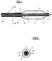
- the interventional catheter shown in Figs. 1 and 2 comprises a catheter tube 1 which is formed, in this embodiment, of two superposed continuous layers 2 and 3 extending all over the length of the tube 1; this tubing, which may be achieved by the known co-extrusion technology, i.e. by extruding the outer layer over the inner layer, is comprised of a polyethylene, preferably a high density polyethylene, for the inner layer 2, and of a polyamid for the outer layer 3.
- the inner layer 2 thus forms a longitudinal lumen 12 with a very low friction coefficient, lower than that of the material forming the outer layer 3, and a non kinking capacity, while the outer layer 3 is easily weldable to the materials commonly used for making balloons for angioplasty and the like.
- a balloon 4 Over the distal portion of the catheter tube 1 is positioned a balloon 4 the distal end 5 of which is sealed to the outer layer 3 of the catheter tube 1, for instance by welding.
- a tube 7 is arranged over the catheter tube 1, at a radial distance thereof, thus defining an inflating lumen 8 for the balloon 4.
- the proximal end 6 of the balloon 4 is welded onto the distal end of said tube 7.
- the tube 7 is exemplified here as being made of two tubes 9 and 10 longitudinally affixed to one another.
- the tubes 9 and 10 shall be made of a polyamid to achieve easy fixing by welding procedures and to obtain a stepped stiffness.
- the proximal end of tube 10 is connected to conventional fittings (not shown) to feed the balloon and drive the catheter assembly.
- a guide wire 11 Inside the catheter tube 1 is placed a guide wire 11 in sliding fit within the inner layer 2 forming the longitudinal lumen 12.
- the two tubes configuration of the tube 7 may be replaced by a single tube or by a configuration having more than two longitudinally affixed tubes.
Abstract
Description
- This invention relates to an interventional catheter comprising a catheter tube having two superposed layers of materials secured in relation to one another and with mechanical properties differing from one another, a longitudinal lumen in said catheter tube for the sliding fit of a guide wire, and a balloon with a proximal end and a distal end, whereby the distal end sealingly surrounds said catheter tube, whereby the catheter tube has an inner layer forming the longitudinal lumen and an outer layer forming the outer surface of the catheter tube, and the inner layer is formed of a material with lower friction coefficient than the material forming the outer layer.
- Over the wire catheters are now widely used for interventions such as percutaneous transluminal angioplasty. A problem with these catheters is that the guide wire may clog into the longitudinal lumen of the catheter; as a result, the guide wire may follow the balloon upon withdrawal thereof after the inflation procedure, thereby making it necessary to re-insert the guide wire into the treated area of the blood vessel for re-positioning a balloon therein in case a second inflation is needed. Apart of this, the catheter has to achieve an acceptable compromise between the requirements of some stiffness to assure good pushability and of some flexibility to assure kink resistance. In addition, the catheter has to permit safe attachment of the balloon to the catheter tube.
- The document WO 92/11893 describes an intra-aortic balloon apparatus comprising a hollow catheter in which is located an elongated member forming a central lumen extending out of the catheter at the distal end thereof. An aortic pumping balloon is positioned over the elongated member; the distal end of the balloon is bonded to a tip affixed to the distal end of the elongated member, and its proximal end is bonded to the distal end of the catheter. In order to achieve a balance of flexibility and remains and to avoid kinking, the elongated member is formed of an inner layer comprised of a soft elastomeric material to impart flexibility to the tubing, and the outer layer is comprised of a hard plastic material to impart structural support to the elongated member. The combination of these two layers is made to achieve a very durable and flexible structure exhibiting a low kink radius. This balloon apparatus cannot be loaded with a guidewire and moved into tortuous vessels with the guidewire loaded inside the elongated tube. The friction between guidewire and the elongated member increases distinctively when the elongated member is shaped into curves. The above procedure would therefore risk that the spiral wound guidewire could be captured in the soft elastomeric plastic material of the inner layer of the elongated member. Although the outer layer of the elongated member that is coextruded onto the inner layer is formed from nylon, a material which is directly weldable to a wide variety of materials, this balloon apparatus cannot be introduced into narrow vessels or narrow stenoses nor can it be passed through narrow punctures to enter the blood vessels. This is because of the relatively large profile of the folded balloon. The large profile is due to the distal fixture of the balloon to the elongated member. The ballon is bonded to an intermediate tip element which in turn is bonded to the elongated member.
- US Patent N° 4,323,071 describes a combination guiding catheter assembly and dilating catheter assembly. The guiding catheter assembly comprises a first flexible tubular member formed of a material with low coefficient of friction and high flexibility; as this first tubular member is too flexible to serve as a guiding catheter because it could not be properly manipulated in the body of a patient, a second tubular member made of a heat shrinkable tubing is provided to encase the first tubular member. The distal end of this assembly is pre-shaped to form a shape corresponding to the standard coronary catheter and the proximal end of the assembly is provided with attachment means to provide a leak-proof adhesive-free connection. The dilating catheter assembly is disposed within the guiding catheter assembly and comprises a first tubular member coaxially disposed within a second tubular member having formed thereon a balloon at its distal end, both these tubular members being made of shrink tubing; an annular flow passage between the first and second tubular members allows introduction of fluid into the balloon for inflation thereof. The proximal end of this assembly is inserted in an adapter body for connection to an appropriate syringe system. A dilator consisting of a flexible plastic tube with a teflon coated guide wire therein is used to position the guiding catheter assembly in the proper location. Within this frame, the guide wire is first inserted conventionally into the blood vessel; the dilator is then positioned in the guiding catheter assembly to straighten it, and the dilator and guiding catheter are passed over the guide wire into the blood vessel; when the guiding catheter is in the proper location, the dilator and guide wire are withdrawn from the guiding catheter and the dilating catheter assembly can be inserted into the guiding catheter assembly, which operation is facilitated by the low coefficient of friction of the first tubular member of the guiding catheter assembly. A small guide wire may be utilized if necessary to precisely position the balloon of the diluting catheter assembly; if so, this small guide wire has to be inserted into the first tubular member of the dilating catheter assembly so that it extends from the distal portion thereof. This guide wire may be removed once the balloon is in the proper location.
- This publication shows a catheter shaft made from a composite material that is achieved by heat shrinking. The material for the inner layer of the composite material is selected from materials rendering low friction. Any instrument inserted into a catheter shaft made from this composite material can easily be moved inside the shaft even after the shaft has been bent and is kept in narrow curves. The shaft for the dilation balloon catheter shown in this publication does not use composite material for its construction. It uses conventional material in one single layer. Because the ballon must be welded or otherwise securely bonded to the catheter shaft to withstand the extraordinary high inflation pressures used in angioplasty, the shaft material for this dilatation balloon catheter has to be selected for good bond characteristics and cannot be selected for good friction characteristics. Therefore this catheter still presents the problem that in tortuous vessels, when the catheter shaft has to follow numerous bends of the vessel, the guidewire can be captured in the shaft. This is specifically troublesome since the dilation catheter has to advance much deeper into the branched vessel system than the guiding catheter which in this publication is shown as made from composite material. For a dilatation catheter the length of the friction creating shaft is longer than the shaft of the guiding catheter and additionally the dilatation catheter shaft is exposed to more vessel curves.
- EP 0 351 687, which is the closest prior art, shows a dilatation catheter having an outer tubular member of low-density polyethylene with a balloon formed at the distal end thereof. An inner tubular member extends coaxially within the outer tubular member and defines an annular passageway therebetween for inflating the balloon. The distal end of the outer tubular member and the distal end of the inner tubular member are joined together by heat sealing or by adhesive to seal the distal end of the balloon. A guidewire extends through an inner lumen in the inner tubular member. The inner tubular member is formed of polyimide and it is provided with a lubricous inner coating or layer made of polytetrafluoroethylene (Teflon) to reduce the friction with the guidewire. The Teflon coating or layer may be formed integral with the inner tubular member or formed as a lining within the tubing.
- US 5,041,100 pertains to a plastic catheter formed of a base material having a friction-reducing coating carried on the outer surface of the base material, the friction reducing coating being of the type that provides friction reduction on hydration thereof. The coating comprises an intimate physical mixture of a structural plastic material and polyethylene oxide.
- The purpose of this invention is to present an interventional low profile balloon catheter that can be moved into tortuous vessels with a guidewire inside the catheter without the risk of the guidewire being captured or clogging in the catheter.
- To this effect, the interventional catheter according to the invention complies with the definitions given in the claims.
- In that way, there is no more risk of having the guide wire clogging in the longitudinal lumen of the catheter tube, in particular upon withdrawal of the balloon. Withdrawal and re-positioning of a balloon for repeated inflation is therefore rapid, safe and precise, because during withdrawal of the balloon the guidewire can be left in place with the tip of the guidewire at the site of the treatment in the vessel system. As the inner polyethylene layer forming the longitudinal lumen is separated from the balloon by the outer polyamid layer, the choice is made towards materials having the most appropriate friction and kink resistance coefficients, while safe attachment of the balloon may be made at will on the outer layer of the catheter tube which is chosen without being influenced by the properties of the inner layer. The outer layer made of a polyamid assures easy welding of the balloon and a good stiffness at that level.
- The inner layer and the outer layer may be congruent in length so that the catheter shaft can be produced in long tubes which are cut into length to form the individual catheter tube.
- Where the two layers of the catheter are produced by extruding the outer layer over the inner layer, a specifically reliable catheter tube is formed in a continuous process. To heat shrink the outer layer onto the inner layer would not allow a continuous process because of the presence of an inner core inside the inner layer. This core has to take up the radial pressure during the heat shrinking process and has to be removed after heat shrinking.
- The seal between the ballon and the catheter tube may be achieved by welding the balloon material to the outer layer of the catheter tube. This allows the design of balloon catheters that withstand the extraordinary high inflation pressures used in angioplasty so that these catheters also show the low clogging risk and the low profile given by the invention.
- In a preferred form of the invention, the inner layer forming the longitudinal lumen of the catheter tube is made of a high density polyethylene which assures an extremely low friction coefficient and an appropriate kink resistance coefficient.
- These and other objects will become readily apparent from the following detailed description with reference to the accompanying drawings which show, diagrammatically and by way of example only, a preferred embodiment of the invention.
- Fig. 1 is a longitudinal cut out of this embodiment.
- Fig. 2 is a section according to line I-I of Fig. 1.
-
- The interventional catheter shown in Figs. 1 and 2 comprises a catheter tube 1 which is formed, in this embodiment, of two superposed
continuous layers inner layer 2, and of a polyamid for theouter layer 3. Theinner layer 2 thus forms alongitudinal lumen 12 with a very low friction coefficient, lower than that of the material forming theouter layer 3, and a non kinking capacity, while theouter layer 3 is easily weldable to the materials commonly used for making balloons for angioplasty and the like. - Over the distal portion of the catheter tube 1 is positioned a balloon 4 the distal end 5 of which is sealed to the
outer layer 3 of the catheter tube 1, for instance by welding. - A
tube 7 is arranged over the catheter tube 1, at a radial distance thereof, thus defining an inflating lumen 8 for the balloon 4. The proximal end 6 of the balloon 4 is welded onto the distal end of saidtube 7. - The
tube 7 is exemplified here as being made of twotubes 9 and 10 longitudinally affixed to one another. Preferably thetubes 9 and 10 shall be made of a polyamid to achieve easy fixing by welding procedures and to obtain a stepped stiffness. The proximal end oftube 10 is connected to conventional fittings (not shown) to feed the balloon and drive the catheter assembly. Inside the catheter tube 1 is placed aguide wire 11 in sliding fit within theinner layer 2 forming thelongitudinal lumen 12. - As a variant, the two tubes configuration of the
tube 7 may be replaced by a single tube or by a configuration having more than two longitudinally affixed tubes.
Claims (3)
- An interventional catheter comprising a catheter tube (1) having two superposed layers (2, 3) of materials secured in relation to one another and with mechanical properties differing from one another, a longitudinal lumen (12) in said catheter tube for the sliding fit of a guide wire (11), and a balloon (4) with a proximal end (6) and a distal end (5), whereby the distal end (5) sealingly surrounds said catheter tube (1), whereby the catheter tube (1) has an inner layer (2) forming the longitudinal lumen (12) and an outer layer (3) forming the outer surface of the catheter tube (1), and the inner layer (2) is formed of a material with lower friction coefficient than the material forming the outer layer (3), characterized in that the inner layer (2) forming the longitudinal lumen (12) of the catheter tube (1) is a polyethylene, the outer layer (3) is made of a polyamid, and the distal end (5) of the balloon (4) is welded to the outer polyamid layer (3) of the catheter tube (1).
- An interventional catheter according to claim 1, wherein the two layers (2, 3) of the catheter tube (1) are produced by extruding the outer layer (3) over the inner layer (2).
- An interventional catheter according to claim 1, wherein the inner layer (2) forming the longitudinal lumen (12) of the catheter tube (1) is a high density polyethylene.
Priority Applications (17)
| Application Number | Priority Date | Filing Date | Title |
|---|---|---|---|
| DK93117403T DK0650740T3 (en) | 1993-10-27 | 1993-10-27 | intervention catheter |
| EP93117403A EP0650740B1 (en) | 1993-10-27 | 1993-10-27 | Interventional catheter |
| AT93117403T ATE184799T1 (en) | 1993-10-27 | 1993-10-27 | INTERVENTIONAL CATHETER |
| ES93117403T ES2136107T3 (en) | 1993-10-27 | 1993-10-27 | CATHETER FOR INTERVENTIONS. |
| DE69326551T DE69326551T2 (en) | 1993-10-27 | 1993-10-27 | Interventional catheter |
| JP6240243A JP2918459B2 (en) | 1993-10-27 | 1994-10-04 | Interventional catheter |
| CA002133698A CA2133698C (en) | 1993-10-27 | 1994-10-05 | Interventional catheter |
| AU77457/94A AU678293B2 (en) | 1993-10-27 | 1994-10-25 | Interventional cathether |
| US08/937,110 US5843032A (en) | 1993-10-27 | 1997-09-24 | Catheter with multilayer tube |
| US09/053,969 US6027477A (en) | 1993-10-27 | 1998-04-02 | Catheter with multilayer tube |
| US09/317,293 US6471673B1 (en) | 1993-10-27 | 1999-05-24 | Catheter with multilayer tube |
| US09/978,964 US6659977B2 (en) | 1993-10-27 | 2001-10-15 | Multilayer interventional catheter |
| US10/280,879 US6960187B2 (en) | 1993-10-27 | 2002-10-25 | Catheter with multilayer tube |
| US10/697,613 US7485108B2 (en) | 1993-10-27 | 2003-10-29 | Multilayer interventional catheter |
| US11/229,301 US7635347B2 (en) | 1993-10-27 | 2005-09-16 | Catheter with multilayer tube |
| US12/361,321 US8066666B2 (en) | 1993-10-27 | 2009-01-28 | Multilayer interventional catheter |
| US12/639,763 US7942849B2 (en) | 1993-10-27 | 2009-12-16 | Catheter with multilayer tube |
Applications Claiming Priority (1)
| Application Number | Priority Date | Filing Date | Title |
|---|---|---|---|
| EP93117403A EP0650740B1 (en) | 1993-10-27 | 1993-10-27 | Interventional catheter |
Publications (2)
| Publication Number | Publication Date |
|---|---|
| EP0650740A1 EP0650740A1 (en) | 1995-05-03 |
| EP0650740B1 true EP0650740B1 (en) | 1999-09-22 |
Family
ID=8213374
Family Applications (1)
| Application Number | Title | Priority Date | Filing Date |
|---|---|---|---|
| EP93117403A Expired - Lifetime EP0650740B1 (en) | 1993-10-27 | 1993-10-27 | Interventional catheter |
Country Status (9)
| Country | Link |
|---|---|
| US (2) | US5843032A (en) |
| EP (1) | EP0650740B1 (en) |
| JP (1) | JP2918459B2 (en) |
| AT (1) | ATE184799T1 (en) |
| AU (1) | AU678293B2 (en) |
| CA (1) | CA2133698C (en) |
| DE (1) | DE69326551T2 (en) |
| DK (1) | DK0650740T3 (en) |
| ES (1) | ES2136107T3 (en) |
Cited By (5)
| Publication number | Priority date | Publication date | Assignee | Title |
|---|---|---|---|---|
| US6165166A (en) | 1997-04-25 | 2000-12-26 | Schneider (Usa) Inc. | Trilayer, extruded medical tubing and medical devices incorporating such tubing |
| US6471673B1 (en) | 1993-10-27 | 2002-10-29 | Schneider (Europe) A.G. | Catheter with multilayer tube |
| US6659977B2 (en) | 1993-10-27 | 2003-12-09 | Schneider (Europe) A.G. | Multilayer interventional catheter |
| EP1941917A2 (en) | 2006-12-22 | 2008-07-09 | BIOTRONIK VI Patent AG | Catheter pipe element |
| US9126026B2 (en) | 2004-03-03 | 2015-09-08 | Innovation Holdings LLC | Rapid exchange balloon catheter with braided shaft |
Families Citing this family (80)
| Publication number | Priority date | Publication date | Assignee | Title |
|---|---|---|---|---|
| DE69002295T2 (en) * | 1989-09-25 | 1993-11-04 | Schneider Usa Inc | MULTILAYER EXTRUSION AS A METHOD FOR PRODUCING BALLOONS FOR VESSEL PLASTICS. |
| ATE184799T1 (en) * | 1993-10-27 | 1999-10-15 | Schneider Europ Gmbh | INTERVENTIONAL CATHETER |
| US5429605A (en) * | 1994-01-26 | 1995-07-04 | Target Therapeutics, Inc. | Microballoon catheter |
| JP3543027B2 (en) * | 1995-04-10 | 2004-07-14 | オリンパス株式会社 | Curved sheath for probe |
| EP0742029A1 (en) * | 1995-05-05 | 1996-11-13 | Schneider (Europe) Ag | Interventional catheter |
| JP3432060B2 (en) * | 1995-09-05 | 2003-07-28 | テルモ株式会社 | Vasodilator |
| DE69625329T3 (en) * | 1996-04-26 | 2012-05-10 | Schneider (Europe) Gmbh | An interventional catheter |
| US6913604B2 (en) * | 1997-02-27 | 2005-07-05 | Cryocath Technologies Inc. | Cryosurgical catheter |
| US6139525A (en) | 1997-07-08 | 2000-10-31 | Advanced Cardiovascular Systems, Inc. | Fusion bonding of catheter components |
| DE69725324T2 (en) * | 1997-10-23 | 2004-08-05 | Schneider (Europe) Gmbh | Seal for a catheter device with dilatation and occlusion balloon |
| US6010521A (en) * | 1997-11-25 | 2000-01-04 | Advanced Cardiovasular Systems, Inc. | Catheter member with bondable layer |
| US6171297B1 (en) | 1998-06-30 | 2001-01-09 | Schneider (Usa) Inc | Radiopaque catheter tip |
| US20020007145A1 (en) | 1998-10-23 | 2002-01-17 | Timothy Stivland | Catheter having improved bonding region |
| US6488655B1 (en) | 1999-06-30 | 2002-12-03 | Advanced Cardiovascular Systems, Inc. | Polymer jacket with adhesive inner layer |
| US6702802B1 (en) | 1999-11-10 | 2004-03-09 | Endovascular Technologies, Inc. | Catheters with improved transition |
| US6447835B1 (en) | 2000-02-15 | 2002-09-10 | Scimed Life Systems, Inc. | Method of coating polymeric tubes used in medical devices |
| US6756094B1 (en) * | 2000-02-28 | 2004-06-29 | Scimed Life Systems, Inc. | Balloon structure with PTFE component |
| US7947059B2 (en) | 2000-03-02 | 2011-05-24 | Boston Scientific Scimed, Inc. | Multilayer medical device |
| US6860960B1 (en) | 2000-09-05 | 2005-03-01 | Scimed Life Systems, Inc. | Method of applying a laser beam around the circumference of a catheter |
| CN1473057A (en) * | 2000-11-09 | 2004-02-04 | ��Ԩ��ѧ��ҵ��ʽ���� | Medical balloon catheter |
| US6436090B1 (en) * | 2000-12-21 | 2002-08-20 | Advanced Cardiovascular Systems, Inc. | Multi lumen catheter shaft |
| US6740191B2 (en) * | 2001-02-22 | 2004-05-25 | Medtronic Ave, Inc. | Through-transmission welding of catheter components |
| US7160432B2 (en) | 2001-03-14 | 2007-01-09 | Applied Materials, Inc. | Method and composition for polishing a substrate |
| US7128825B2 (en) | 2001-03-14 | 2006-10-31 | Applied Materials, Inc. | Method and composition for polishing a substrate |
| US7323416B2 (en) | 2001-03-14 | 2008-01-29 | Applied Materials, Inc. | Method and composition for polishing a substrate |
| US7582564B2 (en) | 2001-03-14 | 2009-09-01 | Applied Materials, Inc. | Process and composition for conductive material removal by electrochemical mechanical polishing |
| US6899804B2 (en) | 2001-12-21 | 2005-05-31 | Applied Materials, Inc. | Electrolyte composition and treatment for electrolytic chemical mechanical polishing |
| US6786886B2 (en) | 2001-08-03 | 2004-09-07 | Scimed Life Systems, Inc. | Method for stabilizing balloon during dilation |
| US20030032999A1 (en) * | 2001-08-07 | 2003-02-13 | Medtronic Ave, Inc. | Balloon stent assembly system and method |
| EP1429683B1 (en) * | 2001-09-28 | 2014-12-24 | Boston Scientific Limited | Medical devices comprising nanomaterials and therapeutic methods utilizing the same |
| US6923787B2 (en) * | 2001-12-20 | 2005-08-02 | Scimed Life Systems, Inc. | Catheter having an improved balloon-to-catheter bond |
| US7914486B2 (en) * | 2001-12-20 | 2011-03-29 | Boston Scientific Scimed, Inc. | Catheter having an improved balloon-to-catheter bond |
| US6855137B2 (en) * | 2002-03-07 | 2005-02-15 | Visionary Biomedical, Inc. | Catheter shaft with coextruded stiffener |
| US7488339B2 (en) | 2002-10-21 | 2009-02-10 | Boston Scientific Scimed, Inc. | Multilayer medical device |
| EP1435253B1 (en) | 2002-12-31 | 2007-01-17 | Abbott Laboratories Vascular Enterprises Limited | Catheter having a more flexible part between shaft and tip and method of manufacturing thereof |
| US6951675B2 (en) * | 2003-01-27 | 2005-10-04 | Scimed Life Systems, Inc. | Multilayer balloon catheter |
| US7393339B2 (en) | 2003-02-21 | 2008-07-01 | C. R. Bard, Inc. | Multi-lumen catheter with separate distal tips |
| DE20303982U1 (en) * | 2003-03-13 | 2003-05-15 | Rehau Ag & Co | Catheter with improved sliding properties |
| US20040243095A1 (en) | 2003-05-27 | 2004-12-02 | Shekhar Nimkar | Methods and apparatus for inserting multi-lumen spit-tip catheters into a blood vessel |
| US7390429B2 (en) | 2003-06-06 | 2008-06-24 | Applied Materials, Inc. | Method and composition for electrochemical mechanical polishing processing |
| US7166099B2 (en) | 2003-08-21 | 2007-01-23 | Boston Scientific Scimed, Inc. | Multilayer medical devices |
| US7491213B2 (en) * | 2004-01-13 | 2009-02-17 | Boston Scientific Scimed, Inc. | Catheter shaft having distal support |
| US8353867B2 (en) * | 2004-05-04 | 2013-01-15 | Boston Scientific Scimed, Inc. | Medical devices |
| US7527606B2 (en) * | 2004-05-27 | 2009-05-05 | Abbott Laboratories | Catheter having main body portion with coil-defined guidewire passage |
| US7815627B2 (en) * | 2004-05-27 | 2010-10-19 | Abbott Laboratories | Catheter having plurality of stiffening members |
| US7658723B2 (en) | 2004-05-27 | 2010-02-09 | Abbott Laboratories | Catheter having plurality of stiffening members |
| US7785318B2 (en) | 2004-05-27 | 2010-08-31 | Abbott Laboratories | Catheter having plurality of stiffening members |
| US7785439B2 (en) | 2004-09-29 | 2010-08-31 | Abbott Laboratories Vascular Enterprises Limited | Method for connecting a catheter balloon with a catheter shaft of a balloon catheter |
| US7794448B2 (en) | 2004-05-27 | 2010-09-14 | Abbott Laboratories | Multiple lumen catheter and method of making same |
| US7628769B2 (en) | 2004-05-27 | 2009-12-08 | Abbott Laboratories | Catheter having overlapping stiffening members |
| US7625353B2 (en) | 2004-05-27 | 2009-12-01 | Abbott Laboratories | Catheter having first and second guidewire tubes and overlapping stiffening members |
| US20070078439A1 (en) * | 2004-05-27 | 2007-04-05 | Axel Grandt | Multiple lumen catheter and method of making same |
| US8992454B2 (en) | 2004-06-09 | 2015-03-31 | Bard Access Systems, Inc. | Splitable tip catheter with bioresorbable adhesive |
| US7166100B2 (en) * | 2004-06-29 | 2007-01-23 | Cordis Neurovascular, Inc. | Balloon catheter shaft design |
| US20060030835A1 (en) * | 2004-06-29 | 2006-02-09 | Sherman Darren R | Catheter shaft tubes and methods of making |
| US8202245B2 (en) * | 2005-01-26 | 2012-06-19 | Boston Scientific Scimed, Inc. | Medical devices and methods of making the same |
| US20060165926A1 (en) * | 2005-01-27 | 2006-07-27 | Jan Weber | Medical devices including nanocomposites |
| US20060224115A1 (en) * | 2005-03-30 | 2006-10-05 | Boston Scientific Scimed, Inc. | Balloon catheter with expandable wire lumen |
| US9352133B2 (en) | 2005-06-09 | 2016-05-31 | Boston Scientific Scimed, Inc. | Balloon catheters with increased column strength |
| US8308711B2 (en) * | 2006-03-06 | 2012-11-13 | Advanced Cardiovascular Systems, Inc. | Catheter shaft with a lubricious surface |
| US7678223B2 (en) | 2006-04-17 | 2010-03-16 | Boston Scientific Scimed, Inc. | Catheter having a multi-section tubular member and method of making the same |
| US8043296B2 (en) * | 2006-08-25 | 2011-10-25 | Kyphon Sarl | Apparatus and methods for use of expandable members in surgical applications |
| MX2009007779A (en) * | 2007-01-22 | 2009-07-30 | Taylor Medical Inc | Catheter with guidewire lumen with tubular portion and sleeve. |
| EP2167180B1 (en) * | 2007-06-01 | 2015-03-04 | Covidien LP | Extension tubes for balloon catheters |
| US8500939B2 (en) * | 2007-10-17 | 2013-08-06 | Bard Access Systems, Inc. | Manufacture of split tip catheters |
| US8292841B2 (en) | 2007-10-26 | 2012-10-23 | C. R. Bard, Inc. | Solid-body catheter including lateral distal openings |
| US8066660B2 (en) | 2007-10-26 | 2011-11-29 | C. R. Bard, Inc. | Split-tip catheter including lateral distal openings |
| US9579485B2 (en) | 2007-11-01 | 2017-02-28 | C. R. Bard, Inc. | Catheter assembly including a multi-lumen configuration |
| WO2009059220A1 (en) | 2007-11-01 | 2009-05-07 | C.R. Bard, Inc. | Catheter assembly including triple lumen tip |
| US8216498B2 (en) | 2008-09-10 | 2012-07-10 | Boston Scientific Scimed, Inc. | Catheter having a coextruded fluoropolymer layer |
| DE102008043541A1 (en) | 2008-11-07 | 2010-05-12 | Biotronik Vi Patent Ag | catheter shaft |
| US8440090B2 (en) | 2010-04-29 | 2013-05-14 | Abbott Cardiovascular Systems Inc. | Apparatus and method of making a variable stiffness multilayer catheter tubing |
| USD748252S1 (en) | 2013-02-08 | 2016-01-26 | C. R. Bard, Inc. | Multi-lumen catheter tip |
| JP6401781B2 (en) | 2013-05-08 | 2018-10-10 | エンボルクス, インク.Embolx, Inc. | Apparatus and method for transvascular tumor embolization with integrated flow regulation |
| US9844383B2 (en) | 2013-05-08 | 2017-12-19 | Embolx, Inc. | Devices and methods for low pressure tumor embolization |
| WO2016011091A1 (en) | 2014-07-14 | 2016-01-21 | C. R. Bard, Inc. | Apparatuses, systems, and methods for inserting split tip catheters having enhanced stiffening and guiding features |
| JP6523727B2 (en) | 2015-03-20 | 2019-06-05 | テルモ株式会社 | catheter |
| US11464948B2 (en) | 2016-02-16 | 2022-10-11 | Embolx, Inc. | Balloon catheters and methods of manufacture and use |
| US10350382B1 (en) | 2018-06-08 | 2019-07-16 | Embolx, Inc. | High torque catheter and methods of manufacture |
| US9550046B1 (en) | 2016-02-16 | 2017-01-24 | Embolx, Inc. | Balloon catheter and methods of fabrication and use |
Citations (7)
| Publication number | Priority date | Publication date | Assignee | Title |
|---|---|---|---|---|
| US3561493A (en) * | 1965-04-21 | 1971-02-09 | Paul Maillard | Composite tubes and method of manufacturing same |
| US4211741A (en) * | 1977-04-07 | 1980-07-08 | Sunlite Plastics, Inc. | Extrusion process for laminated medical-surgical tubing |
| US4335723A (en) * | 1976-11-26 | 1982-06-22 | The Kendall Company | Catheter having inflatable retention means |
| EP0351687A2 (en) * | 1988-07-18 | 1990-01-24 | Advanced Cardiovascular Systems, Inc. | Vascular catheter |
| US4906244A (en) * | 1988-10-04 | 1990-03-06 | Cordis Corporation | Balloons for medical devices and fabrication thereof |
| US5195969A (en) * | 1991-04-26 | 1993-03-23 | Boston Scientific Corporation | Co-extruded medical balloons and catheter using such balloons |
| EP0669142A2 (en) * | 1994-01-31 | 1995-08-30 | Cordis Corporation | Catheter having coextruded tubing |
Family Cites Families (86)
| Publication number | Priority date | Publication date | Assignee | Title |
|---|---|---|---|---|
| US3618614A (en) * | 1969-05-06 | 1971-11-09 | Scient Tube Products Inc | Nontoxic radiopaque multiwall medical-surgical tubings |
| US3695921A (en) * | 1970-09-09 | 1972-10-03 | Nat Patent Dev Corp | Method of coating a catheter |
| US3890976A (en) * | 1972-10-26 | 1975-06-24 | Medical Products Corp | Catheter tip assembly |
| US3814137A (en) * | 1973-01-26 | 1974-06-04 | Baxter Laboratories Inc | Injection site for flow conduits containing biological fluids |
| US4323071A (en) * | 1978-04-24 | 1982-04-06 | Advanced Catheter Systems, Inc. | Vascular guiding catheter assembly and vascular dilating catheter assembly and a combination thereof and methods of making the same |
| US4282876A (en) * | 1979-05-18 | 1981-08-11 | Flynn Vincent J | Radiopaque polyurethane resin compositions |
| US4413989A (en) * | 1980-09-08 | 1983-11-08 | Angiomedics Corporation | Expandable occlusion apparatus |
| DE3337258A1 (en) * | 1982-10-14 | 1984-04-19 | Matburn (Holdings) Ltd., London | DILATATION CATHETER |
| US4596563A (en) * | 1983-06-09 | 1986-06-24 | Cordis Corporation | Thin-walled multi-layered catheter having a fuseless tip |
| US4707389A (en) * | 1983-09-30 | 1987-11-17 | Baxter Travenol Laboratories, Inc. | Multilayer tube, assembly and method |
| US4702252A (en) * | 1983-10-13 | 1987-10-27 | Smiths Industries Public Limited Company | Catheters |
| US4636346A (en) * | 1984-03-08 | 1987-01-13 | Cordis Corporation | Preparing guiding catheter |
| US4597755A (en) * | 1984-05-30 | 1986-07-01 | Advanced Cardiovascular Systems, Inc. | Large bore catheter having flexible tip construction |
| US4646719A (en) * | 1984-06-11 | 1987-03-03 | Aries Medical Incorporated | Intra-aortic balloon catheter having flexible torque transmitting tube |
| DE3442736A1 (en) * | 1984-11-23 | 1986-06-05 | Tassilo Dr.med. 7800 Freiburg Bonzel | DILATATION CATHETER |
| US4627844A (en) * | 1985-10-30 | 1986-12-09 | High Voltage Engineering Corporation | Tri-layer tubing |
| US4921483A (en) * | 1985-12-19 | 1990-05-01 | Leocor, Inc. | Angioplasty catheter |
| US4729914A (en) * | 1985-12-30 | 1988-03-08 | Tyndale Plains-Hunter Ltd. | Hydrophilic coating and substrate coated therewith |
| US4775371A (en) * | 1986-09-02 | 1988-10-04 | Advanced Cardiovascular Systems, Inc. | Stiffened dilatation catheter and method of manufacture |
| US4744366A (en) * | 1986-09-10 | 1988-05-17 | Jang G David | Concentric independently inflatable/deflatable multiple diameter balloon angioplasty catheter systems and method of use |
| US4763654A (en) * | 1986-09-10 | 1988-08-16 | Jang G David | Tandem independently inflatable/deflatable multiple diameter balloon angioplasty catheter systems and method of use |
| JPS63158064A (en) * | 1986-12-23 | 1988-07-01 | テルモ株式会社 | Blood vessel dilating catheter |
| EP0279959B1 (en) * | 1987-01-06 | 1993-08-11 | Advanced Cardiovascular Systems, Inc. | Dilatation catheter with thin guide wire |
| US4782834A (en) * | 1987-01-06 | 1988-11-08 | Advanced Cardiovascular Systems, Inc. | Dual lumen dilatation catheter and method of manufacturing the same |
| US5250069A (en) * | 1987-02-27 | 1993-10-05 | Terumo Kabushiki Kaisha | Catheter equipped with expansible member and production method thereof |
| JPS6415056A (en) * | 1987-07-09 | 1989-01-19 | Hanarou Maeda | Body indwelling tube |
| US4820349A (en) * | 1987-08-21 | 1989-04-11 | C. R. Bard, Inc. | Dilatation catheter with collapsible outer diameter |
| GB2209121B (en) * | 1987-08-25 | 1991-02-13 | Warne Surgical Products Ltd | Catheter |
| JPH01145074A (en) * | 1987-12-01 | 1989-06-07 | Terumo Corp | Balloon catheter |
| US5041089A (en) * | 1987-12-11 | 1991-08-20 | Devices For Vascular Intervention, Inc. | Vascular dilation catheter construction |
| US4900314A (en) * | 1988-02-01 | 1990-02-13 | Fbk International Corporation | Collapse-resistant tubing for medical use |
| US5059269A (en) * | 1988-03-07 | 1991-10-22 | Becton, Dickinson And Company | Method of making an article having a hemocompatible surface |
| US4994047A (en) * | 1988-05-06 | 1991-02-19 | Menlo Care, Inc. | Multi-layer cannula structure |
| US4981478A (en) * | 1988-09-06 | 1991-01-01 | Advanced Cardiovascular Systems | Composite vascular catheter |
| DE68926862T2 (en) * | 1988-10-28 | 1996-11-21 | Kanji Inoue | Balloon catheter assembly |
| CA2007743A1 (en) * | 1989-01-26 | 1990-07-26 | Sachiko Hattori | Vascular catheter with durable lubricious coating |
| US5112304A (en) * | 1989-03-17 | 1992-05-12 | Angeion Corporation | Balloon catheter |
| US4960410A (en) * | 1989-03-31 | 1990-10-02 | Cordis Corporation | Flexible tubular member for catheter construction |
| US5100381A (en) * | 1989-11-13 | 1992-03-31 | Scimed Life Systems, Inc. | Angioplasty catheter |
| US5047045A (en) * | 1989-04-13 | 1991-09-10 | Scimed Life Systems, Inc. | Multi-section coaxial angioplasty catheter |
| US5041100A (en) * | 1989-04-28 | 1991-08-20 | Cordis Corporation | Catheter and hydrophilic, friction-reducing coating thereon |
| US5114423A (en) * | 1989-05-15 | 1992-05-19 | Advanced Cardiovascular Systems, Inc. | Dilatation catheter assembly with heated balloon |
| US5035694A (en) * | 1989-05-15 | 1991-07-30 | Advanced Cardiovascular Systems, Inc. | Dilatation catheter assembly with heated balloon |
| US5006119A (en) * | 1989-05-25 | 1991-04-09 | Engineering & Research Associates, Inc. | Hollow core coaxial catheter |
| US4994018A (en) * | 1989-05-31 | 1991-02-19 | Datascope Corporation | Intra-aortic balloon assembly |
| US5272012A (en) * | 1989-06-23 | 1993-12-21 | C. R. Bard, Inc. | Medical apparatus having protective, lubricious coating |
| GB8916158D0 (en) * | 1989-07-14 | 1989-08-31 | Smiths Industries Plc | Catheters |
| US4976690A (en) * | 1989-08-10 | 1990-12-11 | Scimed Life Systems, Inc. | Variable stiffness angioplasty catheter |
| DE69002295T2 (en) * | 1989-09-25 | 1993-11-04 | Schneider Usa Inc | MULTILAYER EXTRUSION AS A METHOD FOR PRODUCING BALLOONS FOR VESSEL PLASTICS. |
| US5478320A (en) * | 1989-11-29 | 1995-12-26 | Cordis Corporation | Puncture resistant balloon catheter and method of manufacturing |
| US5290306A (en) * | 1989-11-29 | 1994-03-01 | Cordis Corporation | Puncture resistant balloon catheter |
| JP2528011B2 (en) * | 1989-12-20 | 1996-08-28 | テルモ株式会社 | Catheter |
| US5120323A (en) * | 1990-01-12 | 1992-06-09 | Schneider (Usa) Inc. | Telescoping guide catheter system |
| WO1991013648A1 (en) * | 1990-03-15 | 1991-09-19 | W.L. Gore & Associates, Inc. | A catheter liner and a method of making the same |
| IE70756B1 (en) * | 1990-04-11 | 1996-12-30 | Becton Dickinson Co | Radiopaque optically transparent medical tubing |
| US5063018A (en) * | 1990-06-04 | 1991-11-05 | Cordis Corporation | Extrusion method |
| US5423754A (en) * | 1990-09-20 | 1995-06-13 | Scimed Life Systems, Inc. | Intravascular catheter |
| US5085649A (en) * | 1990-11-21 | 1992-02-04 | Flynn Vincent J | Torque controlled tubing |
| WO1992011893A1 (en) * | 1991-01-14 | 1992-07-23 | Kontron Instruments, Inc. | Durable and flexible catheter or central lumen having a low kink radius |
| US5254090A (en) * | 1991-01-14 | 1993-10-19 | Kontron Instruments, Inc. | Balloon catheter having a dual layer inner member |
| US5221270A (en) * | 1991-06-28 | 1993-06-22 | Cook Incorporated | Soft tip guiding catheter |
| US5267959A (en) * | 1991-11-29 | 1993-12-07 | Schneider, Inc. | Laser bonding of angioplasty balloon catheters |
| US5304134A (en) * | 1992-01-17 | 1994-04-19 | Danforth Biomedical, Inc. | Lubricious yet bondable catheter channel sleeve for over-the-wire catheters |
| US5195971A (en) * | 1992-02-10 | 1993-03-23 | Advanced Cardiovascular Systems, Inc. | Perfusion type dilatation catheter |
| US5334169A (en) * | 1992-05-11 | 1994-08-02 | American Interventional Technologies, Inc. | Reinforced catheter with thin monolithic walls |
| US5290230A (en) * | 1992-05-11 | 1994-03-01 | Advanced Cardiovascular Systems, Inc. | Intraluminal catheter with a composite shaft |
| US5439454A (en) * | 1992-05-14 | 1995-08-08 | Baxter International Inc. | Coextruded medical grade port tubing |
| US5356709A (en) * | 1992-05-14 | 1994-10-18 | Baxter International, Inc. | Non-PVC coextruded medical grade port tubing |
| JPH06190052A (en) * | 1992-09-18 | 1994-07-12 | Cordis Corp | Catheter insertion equipment of which fiber is reinforced |
| US5383853A (en) * | 1992-11-12 | 1995-01-24 | Medtronic, Inc. | Rapid exchange catheter |
| JP2735388B2 (en) * | 1993-04-09 | 1998-04-02 | シュナイダー・(ユーエスエイ)・インコーポレーテッド | Dilatation catheter with flexible bumper tip |
| US5348536A (en) * | 1993-08-02 | 1994-09-20 | Quinton Instrument Company | Coextruded catheter and method of forming |
| EP0712354B1 (en) * | 1993-08-06 | 1999-01-13 | Minnesota Mining And Manufacturing Company | Multilayered tubing |
| US5405338A (en) * | 1993-08-19 | 1995-04-11 | Cordis Corporation | Helically wound catheters |
| US5409495A (en) * | 1993-08-24 | 1995-04-25 | Advanced Cardiovascular Systems, Inc. | Apparatus for uniformly implanting a stent |
| EP0738168B1 (en) * | 1993-10-01 | 2004-01-21 | Boston Scientific Corporation | Medical device balloons containing thermoplastic elastomers |
| ATE184799T1 (en) * | 1993-10-27 | 1999-10-15 | Schneider Europ Gmbh | INTERVENTIONAL CATHETER |
| WO1995013110A1 (en) * | 1993-11-12 | 1995-05-18 | Micro Interventional Systems | Small diameter, high torque catheter |
| US5460608A (en) * | 1994-01-25 | 1995-10-24 | Scimed Life Systems, Inc. | Kink free catheter |
| US5533985A (en) * | 1994-04-20 | 1996-07-09 | Wang; James C. | Tubing |
| US5403292A (en) * | 1994-05-18 | 1995-04-04 | Schneider (Usa) Inc. | Thin wall catheter having enhanced torqueability characteristics |
| US5499973A (en) * | 1994-09-08 | 1996-03-19 | Saab; Mark A. | Variable stiffness balloon dilatation catheters |
| US5545151A (en) * | 1994-11-22 | 1996-08-13 | Schneider (Usa) Inc | Catheter having hydrophobic properties |
| ES2181802T3 (en) * | 1994-11-23 | 2003-03-01 | Micro Interventional Systems I | BALLOON CATHETER WITH STRONG TORSION. |
| US5549552A (en) * | 1995-03-02 | 1996-08-27 | Scimed Life Systems, Inc. | Balloon dilation catheter with improved pushability, trackability and crossability |
| US5837313A (en) * | 1995-04-19 | 1998-11-17 | Schneider (Usa) Inc | Drug release stent coating process |
-
1993
- 1993-10-27 AT AT93117403T patent/ATE184799T1/en active
- 1993-10-27 DE DE69326551T patent/DE69326551T2/en not_active Expired - Lifetime
- 1993-10-27 EP EP93117403A patent/EP0650740B1/en not_active Expired - Lifetime
- 1993-10-27 ES ES93117403T patent/ES2136107T3/en not_active Expired - Lifetime
- 1993-10-27 DK DK93117403T patent/DK0650740T3/en active
-
1994
- 1994-10-04 JP JP6240243A patent/JP2918459B2/en not_active Expired - Lifetime
- 1994-10-05 CA CA002133698A patent/CA2133698C/en not_active Expired - Fee Related
- 1994-10-25 AU AU77457/94A patent/AU678293B2/en not_active Ceased
-
1997
- 1997-09-24 US US08/937,110 patent/US5843032A/en not_active Expired - Lifetime
-
1998
- 1998-04-02 US US09/053,969 patent/US6027477A/en not_active Expired - Lifetime
Patent Citations (8)
| Publication number | Priority date | Publication date | Assignee | Title |
|---|---|---|---|---|
| US3561493A (en) * | 1965-04-21 | 1971-02-09 | Paul Maillard | Composite tubes and method of manufacturing same |
| US4335723A (en) * | 1976-11-26 | 1982-06-22 | The Kendall Company | Catheter having inflatable retention means |
| US4211741A (en) * | 1977-04-07 | 1980-07-08 | Sunlite Plastics, Inc. | Extrusion process for laminated medical-surgical tubing |
| EP0351687A2 (en) * | 1988-07-18 | 1990-01-24 | Advanced Cardiovascular Systems, Inc. | Vascular catheter |
| US4906244A (en) * | 1988-10-04 | 1990-03-06 | Cordis Corporation | Balloons for medical devices and fabrication thereof |
| EP0436501B1 (en) * | 1988-10-04 | 1993-04-21 | Cordis Corporation | Balloons for medical devices and fabrication thereof |
| US5195969A (en) * | 1991-04-26 | 1993-03-23 | Boston Scientific Corporation | Co-extruded medical balloons and catheter using such balloons |
| EP0669142A2 (en) * | 1994-01-31 | 1995-08-30 | Cordis Corporation | Catheter having coextruded tubing |
Non-Patent Citations (3)
| Title |
|---|
| "Encyclopedia of Polymer Science", JOHN WILEY , VOLUME 1 , 1985 * |
| "Polymer Handbook 1975", JOHN WILEY * |
| OPTI-Plast from Vas-Cath Inc 1991 * |
Cited By (5)
| Publication number | Priority date | Publication date | Assignee | Title |
|---|---|---|---|---|
| US6471673B1 (en) | 1993-10-27 | 2002-10-29 | Schneider (Europe) A.G. | Catheter with multilayer tube |
| US6659977B2 (en) | 1993-10-27 | 2003-12-09 | Schneider (Europe) A.G. | Multilayer interventional catheter |
| US6165166A (en) | 1997-04-25 | 2000-12-26 | Schneider (Usa) Inc. | Trilayer, extruded medical tubing and medical devices incorporating such tubing |
| US9126026B2 (en) | 2004-03-03 | 2015-09-08 | Innovation Holdings LLC | Rapid exchange balloon catheter with braided shaft |
| EP1941917A2 (en) | 2006-12-22 | 2008-07-09 | BIOTRONIK VI Patent AG | Catheter pipe element |
Also Published As
| Publication number | Publication date |
|---|---|
| CA2133698A1 (en) | 1995-04-28 |
| AU678293B2 (en) | 1997-05-22 |
| CA2133698C (en) | 1999-02-23 |
| DE69326551T2 (en) | 2000-03-02 |
| DE69326551D1 (en) | 1999-10-28 |
| EP0650740A1 (en) | 1995-05-03 |
| JPH07178178A (en) | 1995-07-18 |
| US6027477A (en) | 2000-02-22 |
| AU7745794A (en) | 1995-06-01 |
| ATE184799T1 (en) | 1999-10-15 |
| US5843032A (en) | 1998-12-01 |
| JP2918459B2 (en) | 1999-07-12 |
| DK0650740T3 (en) | 1999-12-20 |
| ES2136107T3 (en) | 1999-11-16 |
Similar Documents
| Publication | Publication Date | Title |
|---|---|---|
| EP0650740B1 (en) | Interventional catheter | |
| US7942849B2 (en) | Catheter with multilayer tube | |
| CA2199333C (en) | Interventional catheter | |
| US7815625B2 (en) | Catheter having improved bonding region | |
| US8066666B2 (en) | Multilayer interventional catheter | |
| US5961510A (en) | Flexible catheter | |
| US4932959A (en) | Vascular catheter with releasably secured guidewire | |
| EP1596898B1 (en) | Balloon catheter | |
| US5315747A (en) | Method of preparing a balloon dilatation catheter | |
| JP4833039B2 (en) | catheter | |
| US20020177841A1 (en) | Dilatation catheter with stiffening wire | |
| JP2003102841A (en) | Balloon catheter |
Legal Events
| Date | Code | Title | Description |
|---|---|---|---|
| PUAI | Public reference made under article 153(3) epc to a published international application that has entered the european phase |
Free format text: ORIGINAL CODE: 0009012 |
|
| 17P | Request for examination filed |
Effective date: 19931104 |
|
| AK | Designated contracting states |
Kind code of ref document: A1 Designated state(s): AT BE CH DE DK ES FR GB IE IT LI NL SE |
|
| 17Q | First examination report despatched |
Effective date: 19960626 |
|
| TPAD | Observations filed by third parties |
Free format text: ORIGINAL CODE: EPIDOS TIPA |
|
| RAP1 | Party data changed (applicant data changed or rights of an application transferred) |
Owner name: SCHNEIDER (EUROPE) GMBH |
|
| GRAG | Despatch of communication of intention to grant |
Free format text: ORIGINAL CODE: EPIDOS AGRA |
|
| GRAG | Despatch of communication of intention to grant |
Free format text: ORIGINAL CODE: EPIDOS AGRA |
|
| GRAH | Despatch of communication of intention to grant a patent |
Free format text: ORIGINAL CODE: EPIDOS IGRA |
|
| GRAH | Despatch of communication of intention to grant a patent |
Free format text: ORIGINAL CODE: EPIDOS IGRA |
|
| GRAA | (expected) grant |
Free format text: ORIGINAL CODE: 0009210 |
|
| AK | Designated contracting states |
Kind code of ref document: B1 Designated state(s): AT BE CH DE DK ES FR GB IE IT LI NL SE |
|
| ITF | It: translation for a ep patent filed |
Owner name: STUDIO APRA' BREVETTI |
|
| REF | Corresponds to: |
Ref document number: 184799 Country of ref document: AT Date of ref document: 19991015 Kind code of ref document: T |
|
| REG | Reference to a national code |
Ref country code: CH Ref legal event code: NV Representative=s name: A. MISRACHI Ref country code: CH Ref legal event code: EP |
|
| REF | Corresponds to: |
Ref document number: 69326551 Country of ref document: DE Date of ref document: 19991028 |
|
| REG | Reference to a national code |
Ref country code: ES Ref legal event code: FG2A Ref document number: 2136107 Country of ref document: ES Kind code of ref document: T3 |
|
| REG | Reference to a national code |
Ref country code: IE Ref legal event code: FG4D |
|
| ET | Fr: translation filed | ||
| REG | Reference to a national code |
Ref country code: DK Ref legal event code: T3 |
|
| PLAV | Examination of admissibility of opposition |
Free format text: ORIGINAL CODE: EPIDOS OPEX |
|
| PLBQ | Unpublished change to opponent data |
Free format text: ORIGINAL CODE: EPIDOS OPPO |
|
| PLBI | Opposition filed |
Free format text: ORIGINAL CODE: 0009260 |
|
| PLAV | Examination of admissibility of opposition |
Free format text: ORIGINAL CODE: EPIDOS OPEX |
|
| PLBF | Reply of patent proprietor to notice(s) of opposition |
Free format text: ORIGINAL CODE: EPIDOS OBSO |
|
| 26 | Opposition filed |
Opponent name: OBSERVAMED PALMA S.L. Effective date: 20000623 |
|
| NLR1 | Nl: opposition has been filed with the epo |
Opponent name: OBSERVAMED PALMA S.L. |
|
| PLBF | Reply of patent proprietor to notice(s) of opposition |
Free format text: ORIGINAL CODE: EPIDOS OBSO |
|
| PLBF | Reply of patent proprietor to notice(s) of opposition |
Free format text: ORIGINAL CODE: EPIDOS OBSO |
|
| REG | Reference to a national code |
Ref country code: GB Ref legal event code: IF02 |
|
| PLBQ | Unpublished change to opponent data |
Free format text: ORIGINAL CODE: EPIDOS OPPO |
|
| PLAB | Opposition data, opponent's data or that of the opponent's representative modified |
Free format text: ORIGINAL CODE: 0009299OPPO |
|
| PLBO | Opposition rejected |
Free format text: ORIGINAL CODE: EPIDOS REJO |
|
| R26 | Opposition filed (corrected) |
Opponent name: OBSERVAMED PALMA S.L. Effective date: 20000623 |
|
| NLR1 | Nl: opposition has been filed with the epo |
Opponent name: OBSERVAMED PALMA S.L. |
|
| PLBO | Opposition rejected |
Free format text: ORIGINAL CODE: EPIDOS REJO |
|
| PUAJ | Public notification under rule 129 epc |
Free format text: ORIGINAL CODE: 0009425 |
|
| 32PN | Public notification |
Free format text: DECISION REJECTING THE OPPOSITION (ART. 102(2) EPC) OF 10.04.2002 TO OBSERVAMED PALMA S.L., CALLE SAN JAIME NO. 6., 07012 PALMA DE MALLORCA, E |
|
| PLBO | Opposition rejected |
Free format text: ORIGINAL CODE: EPIDOS REJO |
|
| PLBN | Opposition rejected |
Free format text: ORIGINAL CODE: 0009273 |
|
| STAA | Information on the status of an ep patent application or granted ep patent |
Free format text: STATUS: OPPOSITION REJECTED |
|
| 27O | Opposition rejected |
Effective date: 20030716 |
|
| NLR2 | Nl: decision of opposition |
Effective date: 20030716 |
|
| PGFP | Annual fee paid to national office [announced via postgrant information from national office to epo] |
Ref country code: SE Payment date: 20100923 Year of fee payment: 18 |
|
| PGFP | Annual fee paid to national office [announced via postgrant information from national office to epo] |
Ref country code: DK Payment date: 20100923 Year of fee payment: 18 Ref country code: AT Payment date: 20100923 Year of fee payment: 18 |
|
| PGFP | Annual fee paid to national office [announced via postgrant information from national office to epo] |
Ref country code: DE Payment date: 20101029 Year of fee payment: 18 |
|
| PGFP | Annual fee paid to national office [announced via postgrant information from national office to epo] |
Ref country code: BE Payment date: 20101013 Year of fee payment: 18 Ref country code: IT Payment date: 20101016 Year of fee payment: 18 |
|
| PGFP | Annual fee paid to national office [announced via postgrant information from national office to epo] |
Ref country code: GB Payment date: 20110930 Year of fee payment: 19 Ref country code: FR Payment date: 20111005 Year of fee payment: 19 |
|
| PGFP | Annual fee paid to national office [announced via postgrant information from national office to epo] |
Ref country code: NL Payment date: 20111020 Year of fee payment: 19 Ref country code: IE Payment date: 20111005 Year of fee payment: 19 Ref country code: ES Payment date: 20111018 Year of fee payment: 19 Ref country code: CH Payment date: 20111026 Year of fee payment: 19 |
|
| BERE | Be: lapsed |
Owner name: *SCHNEIDER EUROPE G.M.B.H. Effective date: 20111031 |
|
| REG | Reference to a national code |
Ref country code: DK Ref legal event code: EBP |
|
| REG | Reference to a national code |
Ref country code: SE Ref legal event code: EUG |
|
| PG25 | Lapsed in a contracting state [announced via postgrant information from national office to epo] |
Ref country code: BE Free format text: LAPSE BECAUSE OF NON-PAYMENT OF DUE FEES Effective date: 20111031 |
|
| PG25 | Lapsed in a contracting state [announced via postgrant information from national office to epo] |
Ref country code: SE Free format text: LAPSE BECAUSE OF NON-PAYMENT OF DUE FEES Effective date: 20111028 Ref country code: DK Free format text: LAPSE BECAUSE OF NON-PAYMENT OF DUE FEES Effective date: 20111031 |
|
| REG | Reference to a national code |
Ref country code: AT Ref legal event code: MM01 Ref document number: 184799 Country of ref document: AT Kind code of ref document: T Effective date: 20111027 |
|
| PG25 | Lapsed in a contracting state [announced via postgrant information from national office to epo] |
Ref country code: AT Free format text: LAPSE BECAUSE OF NON-PAYMENT OF DUE FEES Effective date: 20111027 |
|
| REG | Reference to a national code |
Ref country code: NL Ref legal event code: V1 Effective date: 20130501 |
|
| REG | Reference to a national code |
Ref country code: CH Ref legal event code: PL |
|
| GBPC | Gb: european patent ceased through non-payment of renewal fee |
Effective date: 20121027 |
|
| REG | Reference to a national code |
Ref country code: FR Ref legal event code: ST Effective date: 20130628 |
|
| PG25 | Lapsed in a contracting state [announced via postgrant information from national office to epo] |
Ref country code: LI Free format text: LAPSE BECAUSE OF NON-PAYMENT OF DUE FEES Effective date: 20121031 Ref country code: DE Free format text: LAPSE BECAUSE OF NON-PAYMENT OF DUE FEES Effective date: 20130501 Ref country code: GB Free format text: LAPSE BECAUSE OF NON-PAYMENT OF DUE FEES Effective date: 20121027 Ref country code: CH Free format text: LAPSE BECAUSE OF NON-PAYMENT OF DUE FEES Effective date: 20121031 |
|
| REG | Reference to a national code |
Ref country code: IE Ref legal event code: MM4A |
|
| REG | Reference to a national code |
Ref country code: DE Ref legal event code: R119 Ref document number: 69326551 Country of ref document: DE Effective date: 20130501 |
|
| PG25 | Lapsed in a contracting state [announced via postgrant information from national office to epo] |
Ref country code: NL Free format text: LAPSE BECAUSE OF NON-PAYMENT OF DUE FEES Effective date: 20130501 Ref country code: FR Free format text: LAPSE BECAUSE OF NON-PAYMENT OF DUE FEES Effective date: 20121031 Ref country code: IT Free format text: LAPSE BECAUSE OF NON-PAYMENT OF DUE FEES Effective date: 20121027 |
|
| PG25 | Lapsed in a contracting state [announced via postgrant information from national office to epo] |
Ref country code: IE Free format text: LAPSE BECAUSE OF NON-PAYMENT OF DUE FEES Effective date: 20121027 |
|
| REG | Reference to a national code |
Ref country code: ES Ref legal event code: FD2A Effective date: 20140116 |
|
| PG25 | Lapsed in a contracting state [announced via postgrant information from national office to epo] |
Ref country code: ES Free format text: LAPSE BECAUSE OF NON-PAYMENT OF DUE FEES Effective date: 20121028 |