EP0653723B1 - Scan module with shock protection - Google Patents
Scan module with shock protection Download PDFInfo
- Publication number
- EP0653723B1 EP0653723B1 EP94117879A EP94117879A EP0653723B1 EP 0653723 B1 EP0653723 B1 EP 0653723B1 EP 94117879 A EP94117879 A EP 94117879A EP 94117879 A EP94117879 A EP 94117879A EP 0653723 B1 EP0653723 B1 EP 0653723B1
- Authority
- EP
- European Patent Office
- Prior art keywords
- scan module
- frame
- scanning component
- aperture
- scanning
- Prior art date
- Legal status (The legal status is an assumption and is not a legal conclusion. Google has not performed a legal analysis and makes no representation as to the accuracy of the status listed.)
- Expired - Lifetime
Links
Images


Classifications
-
- G—PHYSICS
- G06—COMPUTING; CALCULATING OR COUNTING
- G06K—GRAPHICAL DATA READING; PRESENTATION OF DATA; RECORD CARRIERS; HANDLING RECORD CARRIERS
- G06K7/00—Methods or arrangements for sensing record carriers, e.g. for reading patterns
- G06K7/10—Methods or arrangements for sensing record carriers, e.g. for reading patterns by electromagnetic radiation, e.g. optical sensing; by corpuscular radiation
- G06K7/10544—Methods or arrangements for sensing record carriers, e.g. for reading patterns by electromagnetic radiation, e.g. optical sensing; by corpuscular radiation by scanning of the records by radiation in the optical part of the electromagnetic spectrum
- G06K7/10821—Methods or arrangements for sensing record carriers, e.g. for reading patterns by electromagnetic radiation, e.g. optical sensing; by corpuscular radiation by scanning of the records by radiation in the optical part of the electromagnetic spectrum further details of bar or optical code scanning devices
- G06K7/10861—Methods or arrangements for sensing record carriers, e.g. for reading patterns by electromagnetic radiation, e.g. optical sensing; by corpuscular radiation by scanning of the records by radiation in the optical part of the electromagnetic spectrum further details of bar or optical code scanning devices sensing of data fields affixed to objects or articles, e.g. coded labels
- G06K7/10871—Methods or arrangements for sensing record carriers, e.g. for reading patterns by electromagnetic radiation, e.g. optical sensing; by corpuscular radiation by scanning of the records by radiation in the optical part of the electromagnetic spectrum further details of bar or optical code scanning devices sensing of data fields affixed to objects or articles, e.g. coded labels randomly oriented data-fields, code-marks therefore, e.g. concentric circles-code
-
- G—PHYSICS
- G06—COMPUTING; CALCULATING OR COUNTING
- G06K—GRAPHICAL DATA READING; PRESENTATION OF DATA; RECORD CARRIERS; HANDLING RECORD CARRIERS
- G06K7/00—Methods or arrangements for sensing record carriers, e.g. for reading patterns
- G06K7/10—Methods or arrangements for sensing record carriers, e.g. for reading patterns by electromagnetic radiation, e.g. optical sensing; by corpuscular radiation
- G06K7/10544—Methods or arrangements for sensing record carriers, e.g. for reading patterns by electromagnetic radiation, e.g. optical sensing; by corpuscular radiation by scanning of the records by radiation in the optical part of the electromagnetic spectrum
- G06K7/10554—Moving beam scanning
- G06K7/10564—Light sources
- G06K7/10584—Source control
-
- G—PHYSICS
- G06—COMPUTING; CALCULATING OR COUNTING
- G06K—GRAPHICAL DATA READING; PRESENTATION OF DATA; RECORD CARRIERS; HANDLING RECORD CARRIERS
- G06K7/00—Methods or arrangements for sensing record carriers, e.g. for reading patterns
- G06K7/10—Methods or arrangements for sensing record carriers, e.g. for reading patterns by electromagnetic radiation, e.g. optical sensing; by corpuscular radiation
- G06K7/10544—Methods or arrangements for sensing record carriers, e.g. for reading patterns by electromagnetic radiation, e.g. optical sensing; by corpuscular radiation by scanning of the records by radiation in the optical part of the electromagnetic spectrum
- G06K7/10554—Moving beam scanning
- G06K7/10594—Beam path
- G06K7/10603—Basic scanning using moving elements
- G06K7/10633—Basic scanning using moving elements by oscillation
- G06K7/10643—Activating means
- G06K7/10653—Activating means using flexible or piezoelectric means
-
- G—PHYSICS
- G06—COMPUTING; CALCULATING OR COUNTING
- G06K—GRAPHICAL DATA READING; PRESENTATION OF DATA; RECORD CARRIERS; HANDLING RECORD CARRIERS
- G06K7/00—Methods or arrangements for sensing record carriers, e.g. for reading patterns
- G06K7/10—Methods or arrangements for sensing record carriers, e.g. for reading patterns by electromagnetic radiation, e.g. optical sensing; by corpuscular radiation
- G06K7/10544—Methods or arrangements for sensing record carriers, e.g. for reading patterns by electromagnetic radiation, e.g. optical sensing; by corpuscular radiation by scanning of the records by radiation in the optical part of the electromagnetic spectrum
- G06K7/10554—Moving beam scanning
- G06K7/10594—Beam path
- G06K7/10603—Basic scanning using moving elements
- G06K7/10673—Parallel lines
-
- G—PHYSICS
- G06—COMPUTING; CALCULATING OR COUNTING
- G06K—GRAPHICAL DATA READING; PRESENTATION OF DATA; RECORD CARRIERS; HANDLING RECORD CARRIERS
- G06K7/00—Methods or arrangements for sensing record carriers, e.g. for reading patterns
- G06K7/10—Methods or arrangements for sensing record carriers, e.g. for reading patterns by electromagnetic radiation, e.g. optical sensing; by corpuscular radiation
- G06K7/10544—Methods or arrangements for sensing record carriers, e.g. for reading patterns by electromagnetic radiation, e.g. optical sensing; by corpuscular radiation by scanning of the records by radiation in the optical part of the electromagnetic spectrum
- G06K7/10554—Moving beam scanning
- G06K7/10594—Beam path
- G06K7/10683—Arrangement of fixed elements
- G06K7/10693—Arrangement of fixed elements for omnidirectional scanning
-
- G—PHYSICS
- G06—COMPUTING; CALCULATING OR COUNTING
- G06K—GRAPHICAL DATA READING; PRESENTATION OF DATA; RECORD CARRIERS; HANDLING RECORD CARRIERS
- G06K7/00—Methods or arrangements for sensing record carriers, e.g. for reading patterns
- G06K7/10—Methods or arrangements for sensing record carriers, e.g. for reading patterns by electromagnetic radiation, e.g. optical sensing; by corpuscular radiation
- G06K7/10544—Methods or arrangements for sensing record carriers, e.g. for reading patterns by electromagnetic radiation, e.g. optical sensing; by corpuscular radiation by scanning of the records by radiation in the optical part of the electromagnetic spectrum
- G06K7/10792—Special measures in relation to the object to be scanned
- G06K7/10801—Multidistance reading
- G06K7/10811—Focalisation
-
- G—PHYSICS
- G06—COMPUTING; CALCULATING OR COUNTING
- G06K—GRAPHICAL DATA READING; PRESENTATION OF DATA; RECORD CARRIERS; HANDLING RECORD CARRIERS
- G06K7/00—Methods or arrangements for sensing record carriers, e.g. for reading patterns
- G06K7/10—Methods or arrangements for sensing record carriers, e.g. for reading patterns by electromagnetic radiation, e.g. optical sensing; by corpuscular radiation
- G06K7/10544—Methods or arrangements for sensing record carriers, e.g. for reading patterns by electromagnetic radiation, e.g. optical sensing; by corpuscular radiation by scanning of the records by radiation in the optical part of the electromagnetic spectrum
- G06K7/10821—Methods or arrangements for sensing record carriers, e.g. for reading patterns by electromagnetic radiation, e.g. optical sensing; by corpuscular radiation by scanning of the records by radiation in the optical part of the electromagnetic spectrum further details of bar or optical code scanning devices
- G06K7/10851—Circuits for pulse shaping, amplifying, eliminating noise signals, checking the function of the sensing device
-
- G—PHYSICS
- G06—COMPUTING; CALCULATING OR COUNTING
- G06K—GRAPHICAL DATA READING; PRESENTATION OF DATA; RECORD CARRIERS; HANDLING RECORD CARRIERS
- G06K7/00—Methods or arrangements for sensing record carriers, e.g. for reading patterns
- G06K7/10—Methods or arrangements for sensing record carriers, e.g. for reading patterns by electromagnetic radiation, e.g. optical sensing; by corpuscular radiation
- G06K7/10544—Methods or arrangements for sensing record carriers, e.g. for reading patterns by electromagnetic radiation, e.g. optical sensing; by corpuscular radiation by scanning of the records by radiation in the optical part of the electromagnetic spectrum
- G06K7/10821—Methods or arrangements for sensing record carriers, e.g. for reading patterns by electromagnetic radiation, e.g. optical sensing; by corpuscular radiation by scanning of the records by radiation in the optical part of the electromagnetic spectrum further details of bar or optical code scanning devices
- G06K7/10881—Methods or arrangements for sensing record carriers, e.g. for reading patterns by electromagnetic radiation, e.g. optical sensing; by corpuscular radiation by scanning of the records by radiation in the optical part of the electromagnetic spectrum further details of bar or optical code scanning devices constructional details of hand-held scanners
- G06K7/10891—Methods or arrangements for sensing record carriers, e.g. for reading patterns by electromagnetic radiation, e.g. optical sensing; by corpuscular radiation by scanning of the records by radiation in the optical part of the electromagnetic spectrum further details of bar or optical code scanning devices constructional details of hand-held scanners the scanner to be worn on a finger or on a wrist
-
- G—PHYSICS
- G06—COMPUTING; CALCULATING OR COUNTING
- G06K—GRAPHICAL DATA READING; PRESENTATION OF DATA; RECORD CARRIERS; HANDLING RECORD CARRIERS
- G06K7/00—Methods or arrangements for sensing record carriers, e.g. for reading patterns
- G06K7/10—Methods or arrangements for sensing record carriers, e.g. for reading patterns by electromagnetic radiation, e.g. optical sensing; by corpuscular radiation
- G06K7/10544—Methods or arrangements for sensing record carriers, e.g. for reading patterns by electromagnetic radiation, e.g. optical sensing; by corpuscular radiation by scanning of the records by radiation in the optical part of the electromagnetic spectrum
- G06K7/10821—Methods or arrangements for sensing record carriers, e.g. for reading patterns by electromagnetic radiation, e.g. optical sensing; by corpuscular radiation by scanning of the records by radiation in the optical part of the electromagnetic spectrum further details of bar or optical code scanning devices
- G06K7/10881—Methods or arrangements for sensing record carriers, e.g. for reading patterns by electromagnetic radiation, e.g. optical sensing; by corpuscular radiation by scanning of the records by radiation in the optical part of the electromagnetic spectrum further details of bar or optical code scanning devices constructional details of hand-held scanners
- G06K7/109—Methods or arrangements for sensing record carriers, e.g. for reading patterns by electromagnetic radiation, e.g. optical sensing; by corpuscular radiation by scanning of the records by radiation in the optical part of the electromagnetic spectrum further details of bar or optical code scanning devices constructional details of hand-held scanners adaptations to make the hand-held scanner useable as a fixed scanner
-
- G—PHYSICS
- G06—COMPUTING; CALCULATING OR COUNTING
- G06K—GRAPHICAL DATA READING; PRESENTATION OF DATA; RECORD CARRIERS; HANDLING RECORD CARRIERS
- G06K7/00—Methods or arrangements for sensing record carriers, e.g. for reading patterns
- G06K7/10—Methods or arrangements for sensing record carriers, e.g. for reading patterns by electromagnetic radiation, e.g. optical sensing; by corpuscular radiation
- G06K7/10544—Methods or arrangements for sensing record carriers, e.g. for reading patterns by electromagnetic radiation, e.g. optical sensing; by corpuscular radiation by scanning of the records by radiation in the optical part of the electromagnetic spectrum
- G06K7/10821—Methods or arrangements for sensing record carriers, e.g. for reading patterns by electromagnetic radiation, e.g. optical sensing; by corpuscular radiation by scanning of the records by radiation in the optical part of the electromagnetic spectrum further details of bar or optical code scanning devices
- G06K7/1098—Methods or arrangements for sensing record carriers, e.g. for reading patterns by electromagnetic radiation, e.g. optical sensing; by corpuscular radiation by scanning of the records by radiation in the optical part of the electromagnetic spectrum further details of bar or optical code scanning devices the scanning arrangement having a modular construction
-
- G—PHYSICS
- G06—COMPUTING; CALCULATING OR COUNTING
- G06K—GRAPHICAL DATA READING; PRESENTATION OF DATA; RECORD CARRIERS; HANDLING RECORD CARRIERS
- G06K2207/00—Other aspects
- G06K2207/1011—Aiming
-
- G—PHYSICS
- G06—COMPUTING; CALCULATING OR COUNTING
- G06K—GRAPHICAL DATA READING; PRESENTATION OF DATA; RECORD CARRIERS; HANDLING RECORD CARRIERS
- G06K2207/00—Other aspects
- G06K2207/1016—Motor control or optical moving unit control
-
- G—PHYSICS
- G06—COMPUTING; CALCULATING OR COUNTING
- G06K—GRAPHICAL DATA READING; PRESENTATION OF DATA; RECORD CARRIERS; HANDLING RECORD CARRIERS
- G06K2207/00—Other aspects
- G06K2207/1018—Source control
Definitions
- This invention relates generally to scanning systems which "read” indicia, such as barcode symbols.
- the barcode symbol itself is a coded pattern of indicia comprised of a series of bars of various widths spaced apart from one another to bound spaces of various widths, the bars and spaces having different light-reflecting characteristics.
- the readers and scanning systems electro-optically transform the graphic indicia into electrical signals, which are decoded into alpha-numerical characters intended to be descriptive of the article or some characteristic of it. Such characters typically are represented in digital form, and utilized as an input to a data processing system for applications in point-of-sale processing, inventory control and the like. Scanning systems of this general type have been disclosed, for example, in U.S. Patent Nos. 4,251,798; 4,360,798; 4,369,361; 4,387,297; 4,409,470 and 4,460,120, all assigned to the assignee of the present invention.
- a scanning system resides in, inter alia, a hand-held, portable laser scanning head supported by a user.
- the scanning head is configured to enable the user to aim the head at a target to emit a light beam toward a symbol to be read.
- the light source is a laser scanner typically in the form of a gas or semiconductor laser element.
- Use of semiconductor devices as the light source in scanning systems is particularly desirable because of the small size, low cost and low power requirements of semiconductor lasers.
- the laser beam is optically modified, typically by a lens, to form a beam spot of a certain size at the target distance.
- the beam spot size at the target distance is approximately the same as the minimum width between regions of different light reflectivity, i.e., the bars and spaces of the symbol.
- a one-dimensional single-line scan functions by repetitively scanning the light beam in a line or series of lines across the symbol using a scanning component such as a mirror -disposed in the light path.
- the scanning component may either sweep the beam spot across the symbol and trace a scan line across and past the symbol, or scan the field in view of the scanner, or do both.
- Scanning systems also include a sensor or photodetector, usually of semiconductor type, which functions to detect light reflected from the symbol.
- the photo-detector is therefore positioned in the scanner or in an optical path in which it has a field of view which extends across and slightly past the symbol.
- a portion of the reflected light which is reflected off the symbol is detected and converted into an electrical signal, and electronic circuitry or software decodes the electrical signal into a digital representation of the data represented by the symbol that has been scanned.
- the analog electrical signal from the photodetector may typically be converted into a pulse width modulated digital signal, with the widths corresponding to the physical widths of the bars and spaces. Such a signal is then decoded according to the specific symbology into a binary representation of the data encoded in the symbol, and to the alphanumeric characters so represented.
- EP-A-0 456 095 discloses a scanner for reading indicia having parts of different light reflectivity by directing light toward the indicia, and by collecting reflected light returning from the indicia, an arrangement for scanning the indicia, comprising a scanner component; holder means for mounting the component for angular oscillating movement in first and second scan directions between first and second pairs of scan end positions; and a read-start means for simultaneously moving the component in the first and second scan directions to simultaneously angularly oscillate the component between the first and second pairs of scan end positions for directing light along the first and second scan directions to thereby effect a two-dimensional scan pattern over the indicia, wherein the holder means includes first and second vibratory means positioned to vibrate in two orthogonal planes and to cooperate for angular oscillating movement of the component in first and second orthogonal scan directions, wherein the actuator includes an electromagnetic coil having a passage, and a magnet mounted on one of the vibratory means and movable into and out of the passage during
- EP-A-0 548 951 discloses a scanning arrangement located within a scanning device which is operative for repetitively scanning indicia having parts of different light reflectivity, for example, bar code symbols, and more particularly, pertains to a novel scanning motor of the arrangement for enabling a scan element which is supported by a holder structure mounted on a Mylar® motor to implement angular oscillatory movements in a linear scan direction between a pair of scan end positions.
- the scanning arrangement is preferably mounted on a single printed circuit board located within a lightweight scanning device of a hand-held housing of gun-shaped configuration which may be readily held and manipulated by a user of the scanning device.
- the structure of the scanning motor and of the scanning arrangement which are mounted on a printed circuit board is considerably simplified through the construction of the various components being essentially of molded plastic material, and through the utilization of a mylar leaf spring which limits the end scan positions of a scan element or mirror which is oscillated by a read-start device including a permanent magnet mounted on an arm of the holder for the scan mirror.
- a scan module for use in a scanner for reading indicia having parts of differing light reflectivity, as set forth in claim 1.
- the scanning component comprises a main bracket (for example of a beryllium copper alloy) which includes a pair of hanging brackets by which the main bracket is secured to the frame.
- Each hanging bracket has attached to it a thin strip of a polyester film, the strip being secured at one end to the hanging bracket and at the other end to the frame.
- the main bracket therefore hangs from the frame on the strips. The strips can flex, allowing the main bracket to oscillate.
- the main bracket desirably carries the optical element, such as a mirror, for directing light shone on to it in a scanning pattern across the indicia to be read.
- the mirror may be secured to the main bracket by a further flexure, allowing the mirror to oscillate independently of the main bracket. If the flexure supporting the mirror and the strips are arranged to flex in mutually perpendicular directions, two dimensional scanning patterns (such as raster patterns) can be produced.
- the strips may be protected from mechanical shock by first and second anti-shock pins which pass through apertures in the hanging brackets.
- the diameter of the central portions of the pins is slightly smaller than the diameter of the apertures, thereby allowing the main bracket to oscillate in use.
- the pins prevent excessive movement of the main bracket, and hence prevent over-stressing of the strips.
- Each anti-shock pin may include an enlarged head portion, which is of substantially the same size and shape in cross section as the aperture in the respective hanging bracket. This allows the main bracket to be accurately positioned with respect to the frame during assembly of the scan module, when the pin is in a partially-inserted position. Once the position has been accurately determined, the main bracket may be secured to the frame, and the pins fully inserted.
- symbol and barcode are intended to be broadly construed and to cover not only patterns composed of alternating bars and spaces of various widths, but also other one or two dimensional graphic patterns, as well as alphanumeric characters.
- Figure 1 shows a scanner which comprises an electromagnetic coil 172 having a central opening into which partially extends and electromagnetic coil 174.
- the coil 172 is rigidly secured to a support member (not shown), and the magnet 174 is resiliently coupled to the same support by means of an arm 176.
- a U-shaped spring 178 is attached to the magnet 174 at one end, and the opposite end of the spring supports an optical element, preferably a reflector 180.
- Electrical leads (not shown) carry an energizing current or drive signal to the coil of electromagnet 174.
- the reflector 180 will oscillate in response to such electromagnet coil signal so as to scan in one or two dimensions, selectively.
- the spring 178 may be made of any suitable flexible materials, such as a leaf spring, a flexible metal coil or a flat bar having sufficient flexibility properties, and may be of a material such as a beryllium-copper alloy.
- the reflector 180 is positioned between a laser beam source and lens assembly 182 and a target (not shown in Figure 1). Between the reflector 180 and source 182 is a collector 184 having an opening through which a light beam emitted by the laser source 182 may pass to the reflector 180. The collector is oriented so as to direct incoming light, reflected by reflector 180 and then collector 184, to a photodetector 186.
- Figure 1 An important aspect of Figure 1 is that the mass of reflector 180 is considerably less than the mass of permanent magnet 174.
- the mass of the mirror is selected to be less than about one-fifth the mass of the magnet, and the angle of vibration of the mirror as shown in Figure 2, a diagram derived by computer simulation, is about seven times that of the permanent magnet.
- the reflector 180 is capable of 2-D scanning.
- the U-shaped spring 178 which may be formed of a plastic material, such as Mylar or Kapton, the arms of the U-shaped spring 178 and the planar spring 176 may be arranged to vibrate in planes . which are orthogonal to each other. Oscillatory forces applied to permanent magnet 174 by the electromagnetic 172 can initiate desired vibrations in both of the springs 178 and 176 by carefully selecting drive signals applied to various terminals of the coil, as discussed in the copending application. Because of the different frequency vibration characteristics of the two springs 178 and 176, each spring will oscillate only at its natural vibration frequency. Hence, when the electromagnetic 172 is driven by a super position signal of high and low frequency components, the U-shaped spring will vibrate at a frequency in the high range of frequencies, and the planar spring 176 will vibrate at a frequency in the low range of frequencies.
- Figure 1 Another important aspect of Figure 1 is in the folded or "retro" configuration shown, with the laser beam source 182 off axis from that of the beam directed from the reflector 180 to the target.
- the detector field of view follows the laser path to the target by way of collector 184.
- the folded configuration shown is made possible by opening 181 in the collector.
- the retro configuration enables the scanning mechanism to be considerably more compact than heretofore possible.
- the preferred scanner module consists of two separate sections: a chassis element 10 and a scan element 12. In Figure 3, these two sections are shown in exploded form, prior to their securement together during the assembly process.
- the chassis element 10 comprises a chassis 14 which carries the coil 172.
- the coil 172 is secured to a rear wall 16 of the chassis.
- At respective ends of the rear wall there are first and second forwardly-extending side supports 18, 20.
- the forward end of the side support 18 is provided with a vertical slot 22 ( Figure 5) into which is placed ( Figure 6) the collecting mirror 184 previously referred to.
- the forward part of the other side support 20 is provided with a larger vertical slot or cavity 24 ( Figure 5) into which the photodiode assembly 186 ( Figure 6) fits.
- the scan element 12 (which is during assembly secured to the chassis element 10) is best seen from a comparison of Figures 3, 4 and 6.
- the scan element comprises a beryllium-copper bracket generally shown at 26 having a vertical mounting portion 28 in a plane perpendicular to the axis of the coil 172.
- the upper part of the mounting portion is formed with two rearwardly-pointing prongs 30, 32 (not visible in Figure 6) which act a counterweights for the mirror 180.
- the spring 178 Secured to the mounting portion 28 is the spring 178, previously mentioned with reference to Figure 1, which carries the mirror 180.
- first and second hanging brackets 34, 36, best seen in Figures 3 and 4. Screwed to these hanging brackets are respective first and second sheets of Mylar film 38, only one of which is visible in Figures 3 to 5.
- At the top of the Mylar sheets are secured respective hangers 40, 42.
- the scanner module is assembled by bringing the scan element 12 up to the chassis element 10 and using screws 44, 46 to attach the hangers 40, 42 to respective bosses 48, 50 on the chassis side supports 18, 20.
- the relative positioning of the chassis element and the scan element, just prior to their securement together by the screws 44, 46 is shown most clearly in Figure 4.
- the entire weight of the scan element including the mirror 180, is supported by the hangers 40, 42 and the sheets of Mylar film 38.
- the entire scan element is accordingly free to rock back and forth about a horizontal axis perpendicular to the axis of the coil 172 as the Mylar film flexes.
- a laser beam emanating from the laser beam source and lens assembly 182, passes through the hole 181 in the collector 184, and impinges upon the mirror 180 from which it is reflected via a window 52 to a bar code symbol to be read (not shown).
- Energisation of the coil 172 causes oscillation of the mirror 180 in two directions: a first direction due to flexing of the spring 178 and a second direction due to flexing of the Mylar film 38.
- a variety of scanning patterns can be produced, for example a raster pattern or other types of two-dimensional pattern.
- the lower end of the hanging bracket 34 is located within a channel or cut out portion 54 formed in the side support 18 of the chassis. As the Mylar film 38 flexes, the hanging bracket 34 moves back and forth within the channel 54. The Mylar film 34 is prevented from over-flexing by the walls of the channel 54 which act as stops. A similar arrangement (not visible in the drawings) is provided on the other side.
- a second level of protection is provided by alignment pins 56, 58, best seen in Figure 3.
- Each pin comprises a threaded rear head portion 60, a reduced diameter smooth waist portion 62, and a smooth forward head portion 64.
- the waist portion 62 of the pin passes through a hole 68 in the hanging bracket 34, with the forward head portion 64 being received within a correspondingly-sized blind bore 70 within one side of the channel 54.
- the rear head portion 60 of the pin is screwed into and held in place by a threaded bore 66 which opens at its forward end into the channel 54 and at its rearward end into the rear surface of the rear wall 16.
- a threaded bore 66 which opens at its forward end into the channel 54 and at its rearward end into the rear surface of the rear wall 16.
- the diameter of the waist portion 62 of the pin is some 0.5 mm (0.02 inches) smaller than the diameter of the hole 68 in the hanging bracket. This provides sufficient tolerance for the Mylar to flex slightly during normal operation of the device. However, if the module is dropped the presence of the pin prevents over-stressing and perhaps breaking of the Mylar.
- the alignment pins have a further function of assisting accurate positioning of the scan element 12 with respect to the chassis during assembly.
- the scan element is brought up into approximately the correct position, and the alignment pins are then inserted as shown in Figure 4.
- the forward head portion 64 is a tight tolerance sliding fit both within the hole 68 in the hanging bracket and in the blind bore 70. This aligns the scan element to the pins and hence to the chassis.
- the scan element is then secured to the chassis, as previously described, using the screws 44, 46.
- the hangers 40, 42 provide a certain amount of adjustability or tolerance in positioning, thereby ensuring that the scan element can be attached to the chassis at the position defined by the alignment pins.
Description
- This invention relates generally to scanning systems which "read" indicia, such as barcode symbols.
- It further relates to a scan module for use in an optical scanner, for example, a bar code scanner.
- Various optical readers and scanning systems have been developed for reading barcode symbols appearing on a label or the surface of an article. The barcode symbol itself is a coded pattern of indicia comprised of a series of bars of various widths spaced apart from one another to bound spaces of various widths, the bars and spaces having different light-reflecting characteristics. The readers and scanning systems electro-optically transform the graphic indicia into electrical signals, which are decoded into alpha-numerical characters intended to be descriptive of the article or some characteristic of it. Such characters typically are represented in digital form, and utilized as an input to a data processing system for applications in point-of-sale processing, inventory control and the like. Scanning systems of this general type have been disclosed, for example, in U.S. Patent Nos. 4,251,798; 4,360,798; 4,369,361; 4,387,297; 4,409,470 and 4,460,120, all assigned to the assignee of the present invention.
- One embodiment of such a scanning system, as disclosed in some of the above patents, resides in, inter alia, a hand-held, portable laser scanning head supported by a user. The scanning head is configured to enable the user to aim the head at a target to emit a light beam toward a symbol to be read. The light source is a laser scanner typically in the form of a gas or semiconductor laser element. Use of semiconductor devices as the light source in scanning systems is particularly desirable because of the small size, low cost and low power requirements of semiconductor lasers. The laser beam is optically modified, typically by a lens, to form a beam spot of a certain size at the target distance.
Preferably, the beam spot size at the target distance is approximately the same as the minimum width between regions of different light reflectivity, i.e., the bars and spaces of the symbol. - A one-dimensional single-line scan, as ordinarily provided by hand-held readers, functions by repetitively scanning the light beam in a line or series of lines across the symbol using a scanning component such as a mirror -disposed in the light path. The scanning component may either sweep the beam spot across the symbol and trace a scan line across and past the symbol, or scan the field in view of the scanner, or do both.
- Scanning systems also include a sensor or photodetector, usually of semiconductor type, which functions to detect light reflected from the symbol. The photo-detector is therefore positioned in the scanner or in an optical path in which it has a field of view which extends across and slightly past the symbol. A portion of the reflected light which is reflected off the symbol is detected and converted into an electrical signal, and electronic circuitry or software decodes the electrical signal into a digital representation of the data represented by the symbol that has been scanned. For example, the analog electrical signal from the photodetector may typically be converted into a pulse width modulated digital signal, with the widths corresponding to the physical widths of the bars and spaces. Such a signal is then decoded according to the specific symbology into a binary representation of the data encoded in the symbol, and to the alphanumeric characters so represented.
- In recent years, it has become more common for bar code scanners to have within them a distinct scanner module containing all the necessary mechanical and optical elements needed to create the scanning of the laser beam and to deal with the incoming reflected beam from the bar code that is being scanned. Using a separate scanner module, within the housing of the bar code scanner, facilitates a modular approach to design and manufacture, thereby keeping costs down, improving reliability, and facilitating the transfer of scanning technology to a variety of scanner housings. A typical prior art scanner module is disclosed in US Patent 4 930 848.
- There are a large number of known ways of mounting a mirror within the scanning component to cause the necessary scanning motion of the laser beam. Some provide for oscillation in only a single direction, so that the scanning laser beam traces out a single path across the bar code being scanned. Others provide two dimensional scanning patterns, such as for example raster patterns or patterns of greater complexity. Examples of scanning components allowing two dimensional scanning are shown in US Patent 5 280 165, and in EP-A-0 540 781.
- EP-A-0 456 095 discloses a scanner for reading indicia having parts of different light reflectivity by directing light toward the indicia, and by collecting reflected light returning from the indicia, an arrangement for scanning the indicia, comprising a scanner component; holder means for mounting the component for angular oscillating movement in first and second scan directions between first and second pairs of scan end positions; and a read-start means for simultaneously moving the component in the first and second scan directions to simultaneously angularly oscillate the component between the first and second pairs of scan end positions for directing light along the first and second scan directions to thereby effect a two-dimensional scan pattern over the indicia, wherein the holder means includes first and second vibratory means positioned to vibrate in two orthogonal planes and to cooperate for angular oscillating movement of the component in first and second orthogonal scan directions, wherein the actuator includes an electromagnetic coil having a passage, and a magnet mounted on one of the vibratory means and movable into and out of the passage during actuation of the coil, wherein the single vibratory means comprises a generally planar spring means having a longitudinal axis and a pivot end secured to a base and wherein the component is mounted to the planar spring means such that the center of gravity of the component is offset from the longitudinal axis, wherein the first vibratory means includes a U-shaped spring means having a pair of arms on one of which is mounted the component and wherein the second vibratory means includes a generally planar spring means having one end secured to a base and a free end secured to the other arm of the U-shaped spring means, the arms of the U-shaped spring means vibrating in one plane and the planar spring torsionally vibrating in the other plane of the two orthogonal planes.
- EP-A-0 548 951 discloses a scanning arrangement located within a scanning device which is operative for repetitively scanning indicia having parts of different light reflectivity, for example, bar code symbols, and more particularly, pertains to a novel scanning motor of the arrangement for enabling a scan element which is supported by a holder structure mounted on a Mylar® motor to implement angular oscillatory movements in a linear scan direction between a pair of scan end positions. Hereby, pursuant to the structure of the scanning device, the scanning arrangement is preferably mounted on a single printed circuit board located within a lightweight scanning device of a hand-held housing of gun-shaped configuration which may be readily held and manipulated by a user of the scanning device. The structure of the scanning motor and of the scanning arrangement which are mounted on a printed circuit board is considerably simplified through the construction of the various components being essentially of molded plastic material, and through the utilization of a mylar leaf spring which limits the end scan positions of a scan element or mirror which is oscillated by a read-start device including a permanent magnet mounted on an arm of the holder for the scan mirror.
- As optical scanning systems have become more complex, and as the demand for smaller size and lower power consumption has increased, shock protection for the scanner modules has become more difficult. These highly efficient scan engines, with both resonant and non-resonant scanning elements are difficult to protect because the scanning element must be free to move for scanning but must be protected in the event of a shock (for example if the user drops the bar code scanner within which the scanner module is incorporated). Also, as sizes are reduced manufacturing tolerances begin to have more significant impacts on costs. Furthermore, it becomes more difficult to achieve accurate optical alignment during assembly, and to maintain that optical alignment during the life of the product.
- It is a general object of the invention at least to alleviate the problems of the prior art.
- It is an additional object to provide a scanner module in which the scanning element is protected against shock.
- It is a further object to provide a scanner module of increased compactness.
- It is a further object to provide a robust, compact scanner module having reduced manufacturing/assembly costs.
- Still other objects and advantages of the present invention will become readily apparent to those skilled in this art from the following detailed description, wherein only the preferred embodiment of the invention is shown and described, simply by way of illustration of the best mode contemplated of carrying out the invention. As will be realized, the invention is capable of other and different embodiments. Accordingly, the drawing and description are to be regarded as illustrative in nature, and not as restrictive.
- According to an aspect of the present invention there is provided a scan module for use in a scanner for reading indicia having parts of differing light reflectivity, as set forth in claim 1.
- According to a further aspect of the invention there is providing a method of assembling a scan module for use in a scanner for reading indicia having parts of differing reflectivity, as set forth in claim 19.
- Preferred embodiments of the present invention may be gathered from the dependent claims.
- Preferably, the scanning component comprises a main bracket (for example of a beryllium copper alloy) which includes a pair of hanging brackets by which the main bracket is secured to the frame. Each hanging bracket has attached to it a thin strip of a polyester film, the strip being secured at one end to the hanging bracket and at the other end to the frame. The main bracket therefore hangs from the frame on the strips. The strips can flex, allowing the main bracket to oscillate.
- The main bracket desirably carries the optical element, such as a mirror, for directing light shone on to it in a scanning pattern across the indicia to be read. The mirror may be secured to the main bracket by a further flexure, allowing the mirror to oscillate independently of the main bracket. If the flexure supporting the mirror and the strips are arranged to flex in mutually perpendicular directions, two dimensional scanning patterns (such as raster patterns) can be produced.
- The strips may be protected from mechanical shock by first and second anti-shock pins which pass through apertures in the hanging brackets. The diameter of the central portions of the pins is slightly smaller than the diameter of the apertures, thereby allowing the main bracket to oscillate in use. However, if a shock is applied to the scan module, the pins prevent excessive movement of the main bracket, and hence prevent over-stressing of the strips.
- Each anti-shock pin may include an enlarged head portion, which is of substantially the same size and shape in cross section as the aperture in the respective hanging bracket. This allows the main bracket to be accurately positioned with respect to the frame during assembly of the scan module, when the pin is in a partially-inserted position. Once the position has been accurately determined, the main bracket may be secured to the frame, and the pins fully inserted.
- The invention may be carried into practice in a number of ways, and one specific embodiment will now be described, by way of example, with reference to the accompanying drawings. The novel features which are considered as characteristic of the invention are set forth in particular in the appended claims. The preferred features of the invention, however, both as to its construction and its method of operation, together with additional objects and advantages thereof, will best be understood from the following description, when read in conjunction with the drawings.
- Figure 1 is a symbolic drawing of a scanning assembly having a low-mass reflector oscillated by a permanent magnet-electromagnet mechanism.
- Figure 2 is a diagram showing that the angle of oscillation of the low-mass reflector is considerably greater than that of the permanent magnet to which it is mechanically coupled.
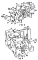
- Figure 3 is an exploded perspective view of a scanner module embodying the present invention;
- Figure 4 is a partially assembled view of the scanner module of Figure 3;
- Figure 5 is a fully assembled view of the scanner module of Figure 3; and
- Figure 6 is a view from below of the scanner module of Figure 3.
-
- As used in this specification, the terms "symbol" and "barcode" are intended to be broadly construed and to cover not only patterns composed of alternating bars and spaces of various widths, but also other one or two dimensional graphic patterns, as well as alphanumeric characters.
- Figure 1 shows a scanner which comprises an
electromagnetic coil 172 having a central opening into which partially extends andelectromagnetic coil 174. Thecoil 172 is rigidly secured to a support member (not shown), and themagnet 174 is resiliently coupled to the same support by means of anarm 176. - A
U-shaped spring 178 is attached to themagnet 174 at one end, and the opposite end of the spring supports an optical element, preferably areflector 180. Electrical leads (not shown) carry an energizing current or drive signal to the coil ofelectromagnet 174. Thereflector 180 will oscillate in response to such electromagnet coil signal so as to scan in one or two dimensions, selectively. Thespring 178 may be made of any suitable flexible materials, such as a leaf spring, a flexible metal coil or a flat bar having sufficient flexibility properties, and may be of a material such as a beryllium-copper alloy. - The
reflector 180 is positioned between a laser beam source andlens assembly 182 and a target (not shown in Figure 1). Between thereflector 180 andsource 182 is acollector 184 having an opening through which a light beam emitted by thelaser source 182 may pass to thereflector 180. The collector is oriented so as to direct incoming light, reflected byreflector 180 and thencollector 184, to aphotodetector 186. - An important aspect of Figure 1 is that the mass of
reflector 180 is considerably less than the mass ofpermanent magnet 174. The mass of the mirror is selected to be less than about one-fifth the mass of the magnet, and the angle of vibration of the mirror as shown in Figure 2, a diagram derived by computer simulation, is about seven times that of the permanent magnet. - The
reflector 180 is capable of 2-D scanning. TheU-shaped spring 178, which may be formed of a plastic material, such as Mylar or Kapton, the arms of theU-shaped spring 178 and theplanar spring 176 may be arranged to vibrate in planes . which are orthogonal to each other. Oscillatory forces applied topermanent magnet 174 by the electromagnetic 172 can initiate desired vibrations in both of thesprings springs planar spring 176 will vibrate at a frequency in the low range of frequencies. - An additional important aspect of Figure 1 is that the laser beam emitted by
source 182 impinges thereflector 180 at an angle that is orthogonal to the axis of rotation of the reflector. Hence, the system avoids droop in the 2-D scan pattern that tends to arise when the angle of incidence of the laser beam is non-orthogonal to the reflective surface. - Another important aspect of Figure 1 is in the folded or "retro" configuration shown, with the
laser beam source 182 off axis from that of the beam directed from thereflector 180 to the target. The detector field of view follows the laser path to the target by way ofcollector 184. The folded configuration shown is made possible by opening 181 in the collector. The retro configuration enables the scanning mechanism to be considerably more compact than heretofore possible. - Reference should next be made to Figures 3 to 6, which illustrate the preferred scanner module within which the scanning arrangement of Figures 1 and 2 may be incorporated. For ease of reference, parts of the module already described with reference to Figures 1 and 2 will be given the same reference numerals.
- As may best be seen in the exploded view of Figure 3, the preferred scanner module consists of two separate sections: a chassis element 10 and a scan element 12. In Figure 3, these two sections are shown in exploded form, prior to their securement together during the assembly process.
- As is best seen in Figures 5 and 6, the chassis element 10 comprises a
chassis 14 which carries thecoil 172. Thecoil 172 is secured to arear wall 16 of the chassis. At respective ends of the rear wall there are first and second forwardly-extending side supports 18, 20. The forward end of theside support 18 is provided with a vertical slot 22 (Figure 5) into which is placed (Figure 6) thecollecting mirror 184 previously referred to. The forward part of theother side support 20 is provided with a larger vertical slot or cavity 24 (Figure 5) into which the photodiode assembly 186 (Figure 6) fits. - The features of the scan element 12 (which is during assembly secured to the chassis element 10) is best seen from a comparison of Figures 3, 4 and 6. The scan element comprises a beryllium-copper bracket generally shown at 26 having a vertical mounting
portion 28 in a plane perpendicular to the axis of thecoil 172. The upper part of the mounting portion is formed with two rearwardly-pointingprongs 30, 32 (not visible in Figure 6) which act a counterweights for themirror 180. Secured to the mountingportion 28 is thespring 178, previously mentioned with reference to Figure 1, which carries themirror 180. On either side of theprongs portion 28 is bent backwardly to form first and second hanging brackets (34, 36, best seen in Figures 3 and 4. Screwed to these hanging brackets are respective first and second sheets ofMylar film 38, only one of which is visible in Figures 3 to 5. At the top of the Mylar sheets are securedrespective hangers - The scanner module is assembled by bringing the scan element 12 up to the chassis element 10 and using
screws hangers respective bosses screws - It will be appreciated that once the scanner module has . been assembled, as described, the entire weight of the scan element, including the
mirror 180, is supported by thehangers Mylar film 38. The entire scan element is accordingly free to rock back and forth about a horizontal axis perpendicular to the axis of thecoil 172 as the Mylar film flexes. - The operation of the device will now be described, with reference to Figure 6. A laser beam, emanating from the laser beam source and
lens assembly 182, passes through thehole 181 in thecollector 184, and impinges upon themirror 180 from which it is reflected via awindow 52 to a bar code symbol to be read (not shown). Energisation of thecoil 172 causes oscillation of themirror 180 in two directions: a first direction due to flexing of thespring 178 and a second direction due to flexing of theMylar film 38. By appropriate control of the coil, a variety of scanning patterns can be produced, for example a raster pattern or other types of two-dimensional pattern. - Light reflected back from the bar code symbol passes back through the
window 52, impinges on themirror 180, and is reflected to thecollector 184. The collector concentrates the light and reflects it back to thephoto detector 186. Decoding circuitry and/or a microprocessor (not shown) then decode the signals received by thephoto detector 186, to determine the data represented by the bar code. - It might be thought that because the entire weight of the scan element 12 is taken by the
Mylar film 38, the system is likely to be very vulnerable to shocks, for example if the user accidentally knocks or even drops the bar code scanner within which the module is contained. However, provision has been made for that contingency by way of an anti-shock feature which will now be described. - First, as may be seen in Figures 4 and 5, the lower end of the hanging
bracket 34 is located within a channel or cut outportion 54 formed in theside support 18 of the chassis. As theMylar film 38 flexes, the hangingbracket 34 moves back and forth within thechannel 54. TheMylar film 34 is prevented from over-flexing by the walls of thechannel 54 which act as stops. A similar arrangement (not visible in the drawings) is provided on the other side. - A second level of protection is provided by
alignment pins rear head portion 60, a reduced diametersmooth waist portion 62, and a smoothforward head portion 64. - In its operational position, shown in Figure 5, the
waist portion 62 of the pin passes through a hole 68 in the hangingbracket 34, with theforward head portion 64 being received within a correspondingly-sized blind bore 70 within one side of thechannel 54. Therear head portion 60 of the pin is screwed into and held in place by a threadedbore 66 which opens at its forward end into thechannel 54 and at its rearward end into the rear surface of therear wall 16. There is a similar arrangement on the other side (not shown) for thesecond alignment pin 58. - The diameter of the
waist portion 62 of the pin is some 0.5 mm (0.02 inches) smaller than the diameter of the hole 68 in the hanging bracket. This provides sufficient tolerance for the Mylar to flex slightly during normal operation of the device. However, if the module is dropped the presence of the pin prevents over-stressing and perhaps breaking of the Mylar. - The alignment pins have a further function of assisting accurate positioning of the scan element 12 with respect to the chassis during assembly. During assembly, the scan element is brought up into approximately the correct position, and the alignment pins are then inserted as shown in Figure 4. At this point, the
forward head portion 64 is a tight tolerance sliding fit both within the hole 68 in the hanging bracket and in theblind bore 70. This aligns the scan element to the pins and hence to the chassis. The scan element is then secured to the chassis, as previously described, using thescrews hangers rear face 16 of the chassis. At this point, as is shown in Figure 5, the forward head portion of the pin has been received within thebore 70, and the waist portion has moved up to its final position within the hole 68 of the hanging bracket.
Claims (28)
- A scan module for use in a scanner for reading indicia having parts of differing light reflectivity, the scan module comprising:a) a framed (10);b) a scanning component (12) mounted to the frame for oscillatory motion, the scanning component including an optical element (180) for directing light in a scanning pattern across an indicia to be read, the scanning component having an aperture (68) therein; andc) an anti-shock member (56, 58), characterized in that said anti-shock member passes through the aperture in the scanning component, the anti-shock member being smaller in cross section than the size of the aperture, thereby providing clearance for the scanning component to oscillate in use, but preventing excessive movement of the scanning component with respect to the frame in the event that the module is subjected to a mechanical shock.
- A scan module as defined in claim 1 wherein the anti-shock member (56, 58) is a pin having a first head portion (60), a second head portion (64), and a waist portion (62) having a smaller cross section than the first and second head portions, the waist portion being located within the aperture (68) during normal operation of the scan module.
- A scan module as defined in claim 2 wherein the first head portion (60) carries an external screw thread which is arranged to be screwed in to a bore (66) in the frame.
- A scan module as defined in claim 2 wherein the second head portion (64) is arranged to be received within a correspondingly-sized bore (70) within the frame.
- A scan module as defined in claim 2 wherein the cross sectional size and shape of the second head portion (64) corresponds with the size and shape of the aperture (68).
- A scan module as defined in claim 5 wherein the second head portion (64) is of such a length that the pin may be positioned with the second head portion contained within the aperture and extending from the aperture in to a correspondingly-sized bore within the frame, thereby locating the scanning component with respect to the frame.
- A scan module as defined in claim 3 wherein the first head portion (60) is substantially flush with the frame when the pin is in a position for normal operation of the scan module.
- A scan module as defined in claim 2 wherein the pin (56, 58) extends across a cut out portion (54) of the frame, the aperture (68) being in a portion of the scanning component which extends into the said cut out portion.
- A scan module as defined in claim 8 wherein the said portion of the scanning component comprises a hanging bracket (34, 36).
- A scan module as defined in claim 1 wherein the aperture (68) is in a portion of the scanning component comprising a hanging bracket (34, 36).
- A scan module as defined in claim 9 or 10 wherein the hanging bracket (34, 36) is supported from the frame by a flexure member (38).
- A scan module as defined in claim 11 wherein the flexure member (38) comprises a polyester material film.
- A scan module as defined in claim 1 wherein the scanning component (12) is supported from the frame (10) by a flexure member (38), the scanning component (12) further including counterweight means (30, 32) balancing the mass of the optical element (180) at the flexure member (38).
- A scan module as defined in claim 13 further including an electromagnetic coil (172) mounted to the frame (10), the counterweight means (30, 32) at least partially overlying the coil (172).
- A scan module as defined in claim 1 wherein the scanning component (12) is supported from the frame (10) by a flexure member (38), and the optical element (180) is supported from the scanning component by a further flexure member (178), the flexure member (38) and the further flexure member (178) being arranged to flex in mutually perpendicular directions.
- A scan module as defined in claim 1 including first and second anti-shock members (56, 58), the first anti-shock member (56) being adjacent a first side of the frame, and the second anti-shock member (58) being adjacent a second side of the frame.
- A scan module as defined in claim 1 wherein the anti-shock member (56, 58) has a longitudinal axis, the movement of the scanning component at the aperture (68), during oscillation, being substantially parallel to said longitudinal axis.
- A scan module as defined in claim 1 wherein the anti-shock member (56, 58) comprises a pin.
- A method of assembling a scan module for use in a scanner for reading indicia having parts of differing reflectivity, the scan module comprising: a frame (10); a scanning component (12) to be mounted to the frame for oscillatory motion, the scanning component including an optical element (180) for directing light in a scanning pattern across an indicia to be read, the scanning component having an aperture (68) therein; and an anti-shock pin (56, 58) having a first head portion (60), a second head portion (64) and a waist portion (62) having a smaller cross section than the first and second head portions; the method comprising:a) positioning the scanning component (12) adjacent to the frame (10);b) partially inserting the pin (56, 58) into the frame so that the second head portion (64) passes through the aperture (68) and extends from the aperture in to a correspondingly-shaped bore (70) in the frame, thereby aligning the scanning component with respect to the frame;c) securing the scanning component (12) to the frame (10);d) continuing insertion of the pin (56, 58) into the frame so that the waist portion (62) of the pin becomes located within the aperture (68), thereby providing clearance for the scanning component to oscillate in use, but preventing excessive movement of the scanning component with respect to the frame in the event that the module is subjected to a mechanical shock.
- A method as defined in claim 19 wherein the first head portion (60) of the pin is threaded, and is received within a corresponding threaded bore (66) within the frame.
- A method as defined in claim 20 wherein the final location of the pin (56, 58), for normal operation of the scan module, is defined by a position in which the first head portion (60) of the pin lies flush with the frame.
- A scan module as defined in any of claims 1 et 18, for use in a scanner for reading indicia having parts of differing light reflectivity,wherein said scanning component (12) comprises a main bracket (26) mounted to the frame by flexible support means (38) for oscillatory motion, the main bracket (26) carrying said optical element for directing light in a scanning pattern across an indicia to be read, the main the bracket (26) having said aperture (68) therein;
the scan module further comprising :d) an electromagnetic coil (172) mounted to the frame;e) magnet means (174) secured to the main bracket (26) adjacent the coil (172);
andf) the main bracket (26) further including a counterweight portion (30, 32) balancing the mass of the optical element (180) at the flexible support means (38), the counterweight portion (30, 32) at least partially overlying the coil (172). - A scan module as defined in claim 22 wherein the frame (10) comprises a first side portion (18), a second side portion (20), and a rear portion (16) connecting the first and second side portions, the electromagnetic coil (172) being mounted between the side portions (18, 20).
- A scan module as defined in claim 23 including an optical collector element (184) mounted to the first side portion (18).
- A scan module as defined in claim 23 including a photodetector unit (186) mounted to the second side portion(20).
- A scan module as defined in claim 23 wherein the first and second side portions (18, 20) have respective cut out portions (54), within which are received respective hanging brackets (34, 36) of the main bracket (26).
- A scan module as defined in claim 26 wherein the hanging brackets (34, 36) are mounted to the frame by respective flexure members (38).
- A scan module as defined in claim 27 wherein the flexure members (38) are polyester material films.
Priority Applications (1)
| Application Number | Priority Date | Filing Date | Title |
|---|---|---|---|
| EP03003186A EP1310903B1 (en) | 1993-11-17 | 1994-11-11 | Compact bar code scanning module with shock protection |
Applications Claiming Priority (4)
| Application Number | Priority Date | Filing Date | Title |
|---|---|---|---|
| US08/153,053 US5504316A (en) | 1990-05-08 | 1993-11-17 | Laser scanning system and scanning method for reading 1-D and 2-D barcode symbols |
| US153053 | 1993-11-17 | ||
| US326328 | 1994-10-20 | ||
| US08/326,328 US5581067A (en) | 1990-05-08 | 1994-10-20 | Compact bar code scanning module with shock protection |
Related Child Applications (1)
| Application Number | Title | Priority Date | Filing Date |
|---|---|---|---|
| EP03003186A Division EP1310903B1 (en) | 1993-11-17 | 1994-11-11 | Compact bar code scanning module with shock protection |
Publications (3)
| Publication Number | Publication Date |
|---|---|
| EP0653723A2 EP0653723A2 (en) | 1995-05-17 |
| EP0653723A3 EP0653723A3 (en) | 2000-02-09 |
| EP0653723B1 true EP0653723B1 (en) | 2003-10-01 |
Family
ID=26850112
Family Applications (2)
| Application Number | Title | Priority Date | Filing Date |
|---|---|---|---|
| EP03003186A Expired - Lifetime EP1310903B1 (en) | 1993-11-17 | 1994-11-11 | Compact bar code scanning module with shock protection |
| EP94117879A Expired - Lifetime EP0653723B1 (en) | 1993-11-17 | 1994-11-11 | Scan module with shock protection |
Family Applications Before (1)
| Application Number | Title | Priority Date | Filing Date |
|---|---|---|---|
| EP03003186A Expired - Lifetime EP1310903B1 (en) | 1993-11-17 | 1994-11-11 | Compact bar code scanning module with shock protection |
Country Status (5)
| Country | Link |
|---|---|
| US (2) | US5581067A (en) |
| EP (2) | EP1310903B1 (en) |
| JP (1) | JPH07254041A (en) |
| CA (1) | CA2136046A1 (en) |
| DE (2) | DE69433196T2 (en) |
Families Citing this family (42)
| Publication number | Priority date | Publication date | Assignee | Title |
|---|---|---|---|---|
| US6575370B1 (en) * | 1990-05-08 | 2003-06-10 | Symbol Technologies, Inc. | Electro-optical scanning assembly with one-piece, oscillatable, focusing/scan element |
| US6227450B1 (en) | 1990-09-11 | 2001-05-08 | Metrologic Instruments, Inc. | Electronically-controlled mechanically-damped off-resonant light beam scanning mechanism and code symbol readers employing the same |
| US6742709B2 (en) | 1990-09-11 | 2004-06-01 | Metrologic Instruments, Inc. | Bar code symbol reading system employing electronically-controlled raster-type laser scanner for reading bar code symbols during hands-on and hands-free modes of operation |
| US6874689B2 (en) | 1990-09-11 | 2005-04-05 | Metrologic Instruments, Inc. | Laser beam scanning device employing a scanning element having a flexible photo-etched gap region disposed between an anchored base portion and a light beam deflecting portion having a natural frequency of oscillation tuned by the physical dimensions of said flexible photo-etched gap region and forcibly oscillated about a fixed pivot point at an electronically-controlled frequency of oscillation substantially different from said natural resonant frequency of oscillation |
| US6114712A (en) * | 1996-10-09 | 2000-09-05 | Symbol Technologies, Inc. | One piece optical assembly for low cost optical scanner |
| NL9400924A (en) * | 1994-06-08 | 1996-01-02 | Scantech Bv | Apparatus for scanning encoded information. |
| US6085978A (en) * | 1994-08-17 | 2000-07-11 | Metrologic Instruments, Inc. | Holographic laser scanners of modular construction and method and apparatus for designing and manufacturing the same |
| JP3379837B2 (en) * | 1994-10-27 | 2003-02-24 | 富士通株式会社 | Optical reader |
| JPH0991368A (en) * | 1995-07-20 | 1997-04-04 | Fujitsu Ltd | Optical reader |
| EP0745950A1 (en) * | 1995-05-30 | 1996-12-04 | Opticon Sensors Europe B.V. | Optical scanning apparatus for generating a helical scanning patern on an external (cylindrical) surface |
| EP0753823A1 (en) * | 1995-07-05 | 1997-01-15 | Opticon Sensors Europe B.V. | Optical scanner for generating scanning lines on all sides of an object |
| US6811086B1 (en) | 1995-07-20 | 2004-11-02 | Fujitsu Limited | Stand for pivotably mounting an optical reading device |
| US6360949B1 (en) | 1995-10-10 | 2002-03-26 | Symbol Technologies, Inc. | Retro-reflective scan module for electro-optical readers |
| US20020014533A1 (en) | 1995-12-18 | 2002-02-07 | Xiaxun Zhu | Automated object dimensioning system employing contour tracing, vertice detection, and forner point detection and reduction methods on 2-d range data maps |
| US5909302A (en) * | 1996-08-02 | 1999-06-01 | Guissin; Rami | Staring scanner |
| US7124950B2 (en) * | 1997-09-16 | 2006-10-24 | Metrologic Instruments, Inc. | Bar code symbol reading system employing electronically-controlled raster-type laser scanner for reading bar code symbols during on hands-on and hands-free modes of operation |
| US7028899B2 (en) | 1999-06-07 | 2006-04-18 | Metrologic Instruments, Inc. | Method of speckle-noise pattern reduction and apparatus therefore based on reducing the temporal-coherence of the planar laser illumination beam before it illuminates the target object by applying temporal phase modulation techniques during the transmission of the plib towards the target |
| US6592040B2 (en) * | 1998-03-20 | 2003-07-15 | Symbol Technologies, Inc. | Hand-held bar code reader with single printed circuit board |
| US6612496B1 (en) | 2000-03-16 | 2003-09-02 | Symbol Technologies, Inc. | Scan module |
| US6941026B1 (en) | 2000-06-13 | 2005-09-06 | Cognex Corporation | Method and apparatus using intensity gradients for visual identification of 2D matrix symbols |
| JP3993094B2 (en) * | 2000-07-27 | 2007-10-17 | 株式会社荏原製作所 | Sheet beam inspection system |
| US6523751B2 (en) * | 2000-12-15 | 2003-02-25 | Yu-Chun Chang | Scanning apparatus |
| JP4364482B2 (en) | 2002-04-23 | 2009-11-18 | 株式会社キーエンス | Optical unit for optical symbol reader |
| US7086596B2 (en) | 2003-01-09 | 2006-08-08 | Hand Held Products, Inc. | Decoder board for an optical reader utilizing a plurality of imaging formats |
| US8002183B2 (en) | 2005-10-20 | 2011-08-23 | Metrologic Instruments, Inc. | Scanner flipper integrity indicator |
| US7614561B2 (en) * | 2005-12-16 | 2009-11-10 | Metrologic Instruments, Inc. | Scanner flipper oscillation frequency detection and adjustment thereof |
| US7832641B2 (en) | 2007-05-24 | 2010-11-16 | Metrologic Instruments, Inc. | Scanner switched to active state by sensed movement in quiescent scanning mechanism |
| US7726575B2 (en) * | 2007-08-10 | 2010-06-01 | Hand Held Products, Inc. | Indicia reading terminal having spatial measurement functionality |
| US8643717B2 (en) * | 2009-03-04 | 2014-02-04 | Hand Held Products, Inc. | System and method for measuring irregular objects with a single camera |
| US8059324B2 (en) | 2009-09-23 | 2011-11-15 | Metrologic Instruments, Inc. | Scan element for use in scanning light and method of making the same |
| US8390909B2 (en) | 2009-09-23 | 2013-03-05 | Metrologic Instruments, Inc. | Molded elastomeric flexural elements for use in a laser scanning assemblies and scanners, and methods of manufacturing, tuning and adjusting the same |
| US8294969B2 (en) * | 2009-09-23 | 2012-10-23 | Metrologic Instruments, Inc. | Scan element for use in scanning light and method of making the same |
| US8748741B2 (en) | 2010-10-25 | 2014-06-10 | Tyco Electronics Corporation | Corrosion resistant multiple tap connectors |
| US8589801B2 (en) * | 2010-11-29 | 2013-11-19 | International Business Machines Corporation | Display screen user identification card for access to secured databases |
| US8915439B2 (en) | 2012-02-06 | 2014-12-23 | Metrologic Instruments, Inc. | Laser scanning modules embodying silicone scan element with torsional hinges |
| WO2013137882A2 (en) * | 2012-03-15 | 2013-09-19 | Optoelectronics Co., Ltd. | Scan unit for a scanning module |
| US8746563B2 (en) | 2012-06-10 | 2014-06-10 | Metrologic Instruments, Inc. | Laser scanning module with rotatably adjustable laser scanning assembly |
| BR112015022386A2 (en) * | 2013-03-15 | 2017-07-18 | Koninklijke Philips Nv | monitor defibrillator |
| US9310609B2 (en) | 2014-07-25 | 2016-04-12 | Hand Held Products, Inc. | Axially reinforced flexible scan element |
| WO2018071684A1 (en) * | 2016-10-12 | 2018-04-19 | Cubic Corporation | Optical sensor for range finding and wind sensing measurements |
| JP7152147B2 (en) * | 2017-12-04 | 2022-10-12 | パイオニア株式会社 | rangefinder |
| US11288469B2 (en) | 2019-12-13 | 2022-03-29 | Zebra Technologies Corporation | Industrial digital barcode reader |
Citations (2)
| Publication number | Priority date | Publication date | Assignee | Title |
|---|---|---|---|---|
| US5235167A (en) * | 1988-10-21 | 1993-08-10 | Symbol Technologies, Inc. | Laser scanning system and scanning method for reading bar codes |
| EP0574024A2 (en) * | 1992-06-12 | 1993-12-15 | Symbol Technologies, Inc. | Adaptive bar code scanner |
Family Cites Families (19)
| Publication number | Priority date | Publication date | Assignee | Title |
|---|---|---|---|---|
| US4845350B1 (en) * | 1982-01-25 | 1991-04-30 | Narrow-bodied,single-and twin-windowed portable laser scanning head for reading bar code symbols | |
| US5122644A (en) * | 1988-11-17 | 1992-06-16 | Alps Electric Co., Ltd. | Optical code reading device with autofocussing |
| US4962980A (en) * | 1989-01-23 | 1990-10-16 | Metrologic Instruments, Inc. | Laser scanner engine with folded beam path |
| US4971410A (en) * | 1989-07-27 | 1990-11-20 | Ncr Corporation | Scanning and collection system for a compact laser |
| JP2808735B2 (en) * | 1989-10-25 | 1998-10-08 | 富士通株式会社 | Separate reader |
| US5206492A (en) * | 1989-10-30 | 1993-04-27 | Symbol Technologies, Inc. | Bar code symbol scanner with reduced power usage to effect reading |
| US5262627A (en) * | 1989-10-30 | 1993-11-16 | Symbol Technologies, Inc. | Scanning arrangement and method |
| US5168149A (en) * | 1989-10-30 | 1992-12-01 | Symbol Technologies, Inc. | Scan pattern generators for bar code symbol readers |
| JP2711158B2 (en) * | 1989-11-13 | 1998-02-10 | 富士写真フイルム株式会社 | Resonant frequency stabilizing method and resonant optical deflector |
| US5115120A (en) * | 1990-06-26 | 1992-05-19 | Photographic Sciences Corporation | Scan modules for bar code readers and in which scan elements are flexurally supported |
| US5268564A (en) * | 1990-08-03 | 1993-12-07 | Symbol Technologies, Inc. | Bar code scanner actuated by detection of scanner motion |
| US5149949A (en) * | 1990-12-10 | 1992-09-22 | Ncr Corporation | Optical scanner with counterrotating reflector elements |
| US5212371A (en) * | 1991-03-01 | 1993-05-18 | Psc, Inc. | Hand held bar code scanner with improved aiming means |
| US5198651A (en) * | 1991-05-03 | 1993-03-30 | Symbol Technologies, Inc. | Laser diode device incorporating structure with integral scanning motor |
| CA2056272C (en) * | 1991-06-14 | 2001-10-16 | Patrick Salatto, Jr. | Combined range laser scanner |
| US5179271A (en) * | 1991-09-19 | 1993-01-12 | Ncr Corporation | Compact optical scan pattern generator for bar code reading systems |
| US5298729A (en) * | 1992-02-14 | 1994-03-29 | Ncr Corporation | Multiple depth of field optical scanner |
| IT1264733B1 (en) * | 1993-11-04 | 1996-10-04 | Datalogic Spa | LASER READING DEVICE OR SCANNER FOR READING CHARACTERS HAVING A DIFFERENT DEGREE OF REFLECTENCE, IN PARTICULAR OF CODES A |
| US5475208A (en) * | 1994-01-27 | 1995-12-12 | Symbol Technologies, Inc. | Barcode scanner having a dead zone reducing system and a multifocal length collector |
-
1994
- 1994-10-20 US US08/326,328 patent/US5581067A/en not_active Expired - Lifetime
- 1994-11-11 EP EP03003186A patent/EP1310903B1/en not_active Expired - Lifetime
- 1994-11-11 DE DE69433196T patent/DE69433196T2/en not_active Expired - Lifetime
- 1994-11-11 DE DE69435305T patent/DE69435305D1/en not_active Expired - Lifetime
- 1994-11-11 EP EP94117879A patent/EP0653723B1/en not_active Expired - Lifetime
- 1994-11-17 CA CA002136046A patent/CA2136046A1/en not_active Abandoned
- 1994-11-17 JP JP6283700A patent/JPH07254041A/en active Pending
-
1996
- 1996-06-05 US US08/658,383 patent/US5763863A/en not_active Expired - Lifetime
Patent Citations (2)
| Publication number | Priority date | Publication date | Assignee | Title |
|---|---|---|---|---|
| US5235167A (en) * | 1988-10-21 | 1993-08-10 | Symbol Technologies, Inc. | Laser scanning system and scanning method for reading bar codes |
| EP0574024A2 (en) * | 1992-06-12 | 1993-12-15 | Symbol Technologies, Inc. | Adaptive bar code scanner |
Also Published As
| Publication number | Publication date |
|---|---|
| DE69435305D1 (en) | 2010-09-02 |
| DE69433196T2 (en) | 2004-07-29 |
| EP1310903B1 (en) | 2010-07-21 |
| EP0653723A3 (en) | 2000-02-09 |
| US5763863A (en) | 1998-06-09 |
| EP0653723A2 (en) | 1995-05-17 |
| JPH07254041A (en) | 1995-10-03 |
| DE69433196D1 (en) | 2003-11-06 |
| US5581067A (en) | 1996-12-03 |
| CA2136046A1 (en) | 1995-05-18 |
| EP1310903A1 (en) | 2003-05-14 |
Similar Documents
| Publication | Publication Date | Title |
|---|---|---|
| EP0653723B1 (en) | Scan module with shock protection | |
| US5486944A (en) | Scanner module for symbol scanning system | |
| EP0368254B1 (en) | Scan modules for bar code readers and the like | |
| EP0818750B1 (en) | Slim scan module | |
| US6527183B2 (en) | One piece optical assembly for low cost optical scanner | |
| US6142379A (en) | Compact bar code scanner with scan mirror jointly movable with drive component | |
| CA2084212C (en) | Scanning arrangement and method | |
| US6929184B2 (en) | Monitoring bi-directional motor drive failure in electro-optical reader | |
| US6491222B1 (en) | Optical path design for scanning assembly in compact bar code readers | |
| US5665954A (en) | Electro-optical scanner module having dual electro-magnetic coils | |
| AU780839B2 (en) | Compact dual optical and scan modules in bar code readers | |
| EP1854045B1 (en) | Scan module | |
| US6722566B1 (en) | Electro-optical scan module using selectable mirrors | |
| US5543609A (en) | Arrangement for and method of providing shock protection and vibration isolation for a scan module | |
| US20050242187A1 (en) | Synchronous and resonant drives for producing multiple scan line pattern for electro-optically reading indicia | |
| EP1209613B1 (en) | Compact bar code scanning arrangement | |
| US6112993A (en) | Flexible dither mount with rotation | |
| CA2111934C (en) | Scanner module for symbol scanning system | |
| WO2006124210A1 (en) | Method and apparatus for shock protection | |
| US7017815B2 (en) | Compact externally-driven scanner | |
| US20060255142A1 (en) | Methods and apparatus for shock protection |
Legal Events
| Date | Code | Title | Description |
|---|---|---|---|
| PUAI | Public reference made under article 153(3) epc to a published international application that has entered the european phase |
Free format text: ORIGINAL CODE: 0009012 |
|
| AK | Designated contracting states |
Kind code of ref document: A2 Designated state(s): DE FR GB IT |
|
| PUAL | Search report despatched |
Free format text: ORIGINAL CODE: 0009013 |
|
| AK | Designated contracting states |
Kind code of ref document: A3 Designated state(s): DE FR GB IT |
|
| 17P | Request for examination filed |
Effective date: 20000802 |
|
| 17Q | First examination report despatched |
Effective date: 20010116 |
|
| GRAG | Despatch of communication of intention to grant |
Free format text: ORIGINAL CODE: EPIDOS AGRA |
|
| RTI1 | Title (correction) |
Free format text: SCAN MODULE WITH SHOCK PROTECTION |
|
| GRAG | Despatch of communication of intention to grant |
Free format text: ORIGINAL CODE: EPIDOS AGRA |
|
| GRAH | Despatch of communication of intention to grant a patent |
Free format text: ORIGINAL CODE: EPIDOS IGRA |
|
| GRAS | Grant fee paid |
Free format text: ORIGINAL CODE: EPIDOSNIGR3 |
|
| GRAA | (expected) grant |
Free format text: ORIGINAL CODE: 0009210 |
|
| AK | Designated contracting states |
Kind code of ref document: B1 Designated state(s): DE FR GB IT |
|
| REG | Reference to a national code |
Ref country code: GB Ref legal event code: FG4D |
|
| REF | Corresponds to: |
Ref document number: 69433196 Country of ref document: DE Date of ref document: 20031106 Kind code of ref document: P |
|
| RAP2 | Party data changed (patent owner data changed or rights of a patent transferred) |
Owner name: SYMBOL TECHNOLOGIES, INC. |
|
| ET | Fr: translation filed | ||
| PLBE | No opposition filed within time limit |
Free format text: ORIGINAL CODE: 0009261 |
|
| STAA | Information on the status of an ep patent application or granted ep patent |
Free format text: STATUS: NO OPPOSITION FILED WITHIN TIME LIMIT |
|
| 26N | No opposition filed |
Effective date: 20040702 |
|
| REG | Reference to a national code |
Ref country code: DE Ref legal event code: R082 Ref document number: 69433196 Country of ref document: DE Representative=s name: SCHUMACHER & WILLSAU PATENTANWALTSGESELLSCHAFT, DE |
|
| PGFP | Annual fee paid to national office [announced via postgrant information from national office to epo] |
Ref country code: DE Payment date: 20121130 Year of fee payment: 19 Ref country code: FR Payment date: 20121113 Year of fee payment: 19 |
|
| PGFP | Annual fee paid to national office [announced via postgrant information from national office to epo] |
Ref country code: IT Payment date: 20121119 Year of fee payment: 19 Ref country code: GB Payment date: 20121025 Year of fee payment: 19 |
|
| GBPC | Gb: european patent ceased through non-payment of renewal fee |
Effective date: 20131111 |
|
| REG | Reference to a national code |
Ref country code: FR Ref legal event code: ST Effective date: 20140731 |
|
| REG | Reference to a national code |
Ref country code: DE Ref legal event code: R119 Ref document number: 69433196 Country of ref document: DE Effective date: 20140603 |
|
| PG25 | Lapsed in a contracting state [announced via postgrant information from national office to epo] |
Ref country code: IT Free format text: LAPSE BECAUSE OF NON-PAYMENT OF DUE FEES Effective date: 20131111 Ref country code: DE Free format text: LAPSE BECAUSE OF NON-PAYMENT OF DUE FEES Effective date: 20140603 |
|
| PG25 | Lapsed in a contracting state [announced via postgrant information from national office to epo] |
Ref country code: GB Free format text: LAPSE BECAUSE OF NON-PAYMENT OF DUE FEES Effective date: 20131111 Ref country code: FR Free format text: LAPSE BECAUSE OF NON-PAYMENT OF DUE FEES Effective date: 20131202 |