EP0656190B1 - Apparatus for applying surgical clips - Google Patents
Apparatus for applying surgical clips Download PDFInfo
- Publication number
- EP0656190B1 EP0656190B1 EP94115677A EP94115677A EP0656190B1 EP 0656190 B1 EP0656190 B1 EP 0656190B1 EP 94115677 A EP94115677 A EP 94115677A EP 94115677 A EP94115677 A EP 94115677A EP 0656190 B1 EP0656190 B1 EP 0656190B1
- Authority
- EP
- European Patent Office
- Prior art keywords
- clip
- jaw
- jaw mechanism
- handle
- rack
- Prior art date
- Legal status (The legal status is an assumption and is not a legal conclusion. Google has not performed a legal analysis and makes no representation as to the accuracy of the status listed.)
- Expired - Lifetime
Links
- 0 C[C@](C1=C)C1=C(C)C(C(C=CC=C/C=[N+](/N(C)N=*)\[O-])=C)=C Chemical compound C[C@](C1=C)C1=C(C)C(C(C=CC=C/C=[N+](/N(C)N=*)\[O-])=C)=C 0.000 description 1
Images


Classifications
-
- A—HUMAN NECESSITIES
- A61—MEDICAL OR VETERINARY SCIENCE; HYGIENE
- A61B—DIAGNOSIS; SURGERY; IDENTIFICATION
- A61B17/00—Surgical instruments, devices or methods, e.g. tourniquets
- A61B17/12—Surgical instruments, devices or methods, e.g. tourniquets for ligaturing or otherwise compressing tubular parts of the body, e.g. blood vessels, umbilical cord
- A61B17/128—Surgical instruments, devices or methods, e.g. tourniquets for ligaturing or otherwise compressing tubular parts of the body, e.g. blood vessels, umbilical cord for applying or removing clamps or clips
- A61B17/1285—Surgical instruments, devices or methods, e.g. tourniquets for ligaturing or otherwise compressing tubular parts of the body, e.g. blood vessels, umbilical cord for applying or removing clamps or clips for minimally invasive surgery
-
- A—HUMAN NECESSITIES
- A61—MEDICAL OR VETERINARY SCIENCE; HYGIENE
- A61B—DIAGNOSIS; SURGERY; IDENTIFICATION
- A61B17/00—Surgical instruments, devices or methods, e.g. tourniquets
- A61B17/28—Surgical forceps
- A61B17/29—Forceps for use in minimally invasive surgery
- A61B2017/2926—Details of heads or jaws
- A61B2017/2927—Details of heads or jaws the angular position of the head being adjustable with respect to the shaft
- A61B2017/2929—Details of heads or jaws the angular position of the head being adjustable with respect to the shaft with a head rotatable about the longitudinal axis of the shaft
-
- Y—GENERAL TAGGING OF NEW TECHNOLOGICAL DEVELOPMENTS; GENERAL TAGGING OF CROSS-SECTIONAL TECHNOLOGIES SPANNING OVER SEVERAL SECTIONS OF THE IPC; TECHNICAL SUBJECTS COVERED BY FORMER USPC CROSS-REFERENCE ART COLLECTIONS [XRACs] AND DIGESTS
- Y10—TECHNICAL SUBJECTS COVERED BY FORMER USPC
- Y10S—TECHNICAL SUBJECTS COVERED BY FORMER USPC CROSS-REFERENCE ART COLLECTIONS [XRACs] AND DIGESTS
- Y10S227/00—Elongated-member-driving apparatus
- Y10S227/901—Surgical clip appliers
Definitions
- This invention relates to an apparatus for applying surgical clips to body tissue during laparoscopic or endoscopic procedures, and more particularly, to a surgical clip applier adapted to apply fully crimped clips as well as a partially formed clip during surgical procedures.
- a surgical clip applier adapted to apply fully crimped clips as well as a partially formed clip during surgical procedures.
- Such apparatus is diclosed in US-A-5084057, in relation to which prior art, claim 1 below is differentiated.
- a small incision is made in the patient's body to provide access for a tube or cannula device.
- the cannula Once extended into the patient's body, the cannula provides an access port which allows insertion of various surgical instruments through the cannula for acting on organs, blood vessels, ducts, or body tissue far removed from the incision.
- the surgical procedure may necessitate the temporary implantation of shunts or tubes into ducts or vessels.
- Such procedures, such as gall bladder surgery often require the placement of a shunt into the ducts during excision of the organ.
- a clip To secure the shunt, a clip must be applied which is partially closed so as to avoid occluding the shunt. While instruments for performing surgical clip application are known in the art, none provide indication of the successful application of a partially crimped clip, such as is necessary to secure the shunt. Fully crimping a clip over a shunt will obviously occlude the shunt and defeat its purpose.
- the jaw members are constructed so as to have a gap between the crimping surface of each jaw member which is slightly less than the distance between the legs of a clip, so that the clip is slightly pinched between the jaws to hold the clip therein.
- Another method of maintaining the clip within the jaws is to machine the crimping surfaces of the jaw members to have a clip accepting slot.
- This increases cost and requires precision during the machining process to provide the proper dimensions for end use.
- the jaw members are typically a costly item since they are machined from a single piece to form the crimping surfaces.
- the clip tends to fall out of the jaws, and potentially, into the patient's body.
- the clip advancement mechanism may not properly orient the clip if the jaws are not properly spaced.
- some instruments may provide some clip alignment feature or clip stop mechanism, these are typically internal mechanisms which operate in conjunction with the clip supply, not the jaw mechanisms, such as disclosed in U.S. Patent Nos. 5,192,288 and 4,616,650.
- the clip may become dislodged, or slightly deviate off-line, there is no provision in the prior art for holding or guiding the clip into the jaws.
- some instruments may provide tabs to align the clip at the clip supply, such as disclosed in U.S. Patent No. 4,492,262, there is no provision to support the clip outside the instrument at the jaws.
- a clip applicator which may be used in endoscopic or laparoscopic procedures such as gall bladder operations which is configured to partially close and release a clip to secure shunts during the procedure.
- a need exists for a clip applier which accurately advances and holds a clip in the jaw mechanism and which prevents splaying of the jaws in the event of a clip over clip application.
- An instrument is also needed which provides a visual indication of the position of the jaw mechanism, and may also provide an audible and tactile indication.
- An instrument is also needed which prevents feeding of a clip in the event the jaws are not fully opened, as well as an instrument which provides for facile rotation of the instrument's body portion.
- a novel clip applier of the present invention obviates the disadvantages encountered in the prior art and provides a cost-effective instrument which ensures accurate and efficient application of clips during a surgical procedure.
- the clip applier of the present invention provides an instrument which allows the surgeon to apply partially closed clips during a gall bladder operation to permit securement of shunts in organs without occluding the shunt, and provides visual, audible and/or tactile indication of when the jaws are in a predetermined position to permit the surgeon to release pressure on the handles to release the partially closed clip.
- the instrument of the present invention substantially reduces the possibility of clips inadvertently falling out of the jaws, and prevents splaying of the jaws beyond the initial clip-receiving gap between the crimping surfaces in the event a clip is applied over a previously applied clip.
- the instrument also prevents a clip from being fed to the jaws in the event the jaws are not fully opened, and includes a clip holding feature associated with the clip advancing mechanism to hold a clip to ensure correct positioning between the jaw members.
- the instrument also permits facile rotation of body portion with respect to its longitudinal orientation through the provision of a novel rotation collar.
- the present invention provides an apparatus for applying surgical clips to vessels and ducts in a patient which comprises a handle portion, a body portion which extends distally from the handle portion, a clip supply for storing a plurality of surgical clips in a position for sequential advancement towards a distal end of the body portion, a jaw mechanism disposed at the distal end of the body portion which is movable between an open position for receiving a clip and a closed position for forming a clip in response to movement of the handle portion, means for advancing a clip from the clip supply to the jaw mechanism and means which will affect a partial closure of a clip positioned in the jaw mechanism.
- the closing mechanism provides a means for affecting a closing stroke of the jaw mechanism from the open position to the closed position and includes means for permitting at least a partial opening stroke of the jaw mechanism after at least a partial closing stroke is completed.
- the instrument provides the surgeon with a means for crimping a clip partially and then opening the jaws a sufficient distance to release the partially closed clip.
- the closing mechanism of the instrument requires a full closing stroke of the handle mechanism prior to feeding a subsequent clip to the jaw mechanism.
- the present invention provides the surgeon with an apparatus which will allow him to apply surgical clips to ducts within the body and further provides a means for the temporary implantation of shunts or tubes in ducts by allowing partial closure of a clip without fully forming the clip to prevent occlusion of the duct or implanted shunt.
- the instrument provides a tactile indication of the position of the jaw mechanism so that the surgeon knows when the jaw mechanism has closed a sufficient distance to place the jaws in a predetermined zone or position in which the clip is partially closed for application to the duct or shunt at the surgical site.
- the instrument may further provide audible indication of the position of the jaws in the predetermined zone, and further may include visual indication means which will give the surgeon a visual indication of when the jaws are in the predetermined zone.
- the instrument allows the surgeon to partially open the handle mechanism to release pressure on the partially closed clip to allow the clip to be removed or released from the jaw mechanism. Upon release of the partially closed clip, the surgeon continues the closing stroke to reset the instrument to place it in a position for a subsequent use.
- the tactile and audible indicators essentially comprise a ratchet mechanism positioned within the handle portion of the clip applying instrument of the present invention.
- the ratchet mechanism includes a rack member positioned within the handle portion and a pawl member which is preferably positioned on the pivoting handle of the handle portion. The pawl member engages the rack member upon commencement of the closing stroke of the handle portion. Once the pawl member engages the rack, the movable handle is permitted to move in a closing direction towards the stationary hand grip, but is prevented from moving in an opening stroke away from the stationary hand grip.
- the pawl member is released from the rack member, which allows the surgeon to effect a partial opening stroke of the movable handle, which provides a corresponding partial opening stroke of the jaw mechanism, and the partially closed clip is released from the jaw mechanism.
- the partial opening stroke of the handle portion will terminate when the pawl member re-engages the rack member and in order to reuse the instrument, the surgeon must complete the closing stroke of the movable handle of the handle portion.
- the rack and pawl assembly provides an audible indication of when the jaw members are in the proper zone to effect release of the partially closed clip.
- an audible clicking sound may be heard as the pawl passes over the teeth of the rack member.
- the jaw members are in the proper position, i.e., the jaws are partially closed to partially close a clip position therebetween, the pawl member leaves the teeth of the rack member so that the clicking sound has ceased.
- the surgeon will know that a partial opening stroke may be affected to release the clip positioned between the jaws.
- the pawl will then re-engage the rack member to terminate the opening stroke, and the surgeon knows that he must complete the closing stroke to reload the instrument.
- the pawl and rack mechanism also provides the surgeon with a tactile indication by allowing him to "feel" the instrument when it is in the predetermined zone for partial closure of a clip.
- the surgeon moves the movable handle towards the stationary hand grip and the pawl passes over the teeth of the rack, the surgeon can feel the clicking of the pawl over the teeth of the rack.
- the surgeon no longer feels the pawl passing over the teeth of the rack, he will know that the jaws are in the predetermined zone for partially closing a clip, and can release the force on the movable handle to effect a partial opening stroke of the movable handle and allow the partially closed clip to be released from the jaw mechanism.
- the ratchet mechanism disclosed in the handle portion preferably comprises a rack member having a plurality of teeth over a first distance and a plurality of teeth over a second distance which is separated by a space having no teeth.
- the rack member may comprise a pair of rack members positioned in a series relationship which is separated by a distance. As the pawl member travels the distance between the two rack members, the surgeon will know that the jaw members are in the predetermined zone to release the partially closed clip.
- the rack member may include teeth over a distance corresponding to a partial closing stroke so that once the pawl member passes the rack member, the surgeon will know that the jaw members are in the predetermined zone for releasing a partially closed clip. The rack member will ensure that the partial opening stroke which will release the partially closed clip will be terminated once the pawl member re-engages the rack member. The surgeon must then fully close the handle portion to reset the instrument to position a subsequent clip in the jaw mechanism for the next use.
- the ratchet mechanism include a pair of rack members positioned in parallel relationship, where the first rack includes teeth over at least a partial closing distance and does not provide teeth for a portion of the closing stroke which will allow the surgeon to partially open the handle portion to release a partially closed clip positioned in the jaw mechanism.
- the second rack member positioned next to the first rack member will include teeth over the distance in which the first rack member is devoid of teeth.
- the teeth of the second rack member are spaced differently from the teeth of the first rack member so that the surgeon knows from the audible indication of the change in rack members that the jaw mechanism is in the predetermined zone for effecting a partial opening stroke of the handle portion to release the clip which is partially closed in the jaw mechanism.
- one or two pawl members may be provided, or when a single pawl member is provided, a portion of the movable handle may engage the second rack member to provide the audible indication of the predetermined zone of the jaw mechanism.
- the present invention also contemplates the provision of a visual indication for the surgeon, outside the patient's body, of the position of the jaw members, particularly when the jaw members are in the predetermined position or zone for partially closing a clip positioned between the jaw members.
- the visual indication may be provided on an instrument having the ratchet mechanism inside the handle.
- the instrument may provide visible, audible and tactile indications of the position of the jaw mechanism.
- a first transmission means is provided for a linearly transferring motion from the movable handle to the clip advancing means, and a second transmission means for linearly transferring motion from the movable handle to the jaw closing means.
- the first transmission means which operates the clip advancement means comprises a pusher tube which is operatively connected to a pusher bar which extends the length of the instrument to push clips from the clip supply to the jaw mechanism.
- the second transmission means which operates the jaw closing means comprises a channel tube which is operatively connected to a sliding channel which extends the length of the body portion to effect opening and closing of the jaw members.
- an indicator or flag is provided on the channel tube which is visible through an aperture or window in the handle portion. When the instrument is at rest, such that the jaw members are fully opened to receive a clip therebetween, the flag on the channel tube is positioned within the handle away from the window or aperture.
- the channel tube moves forward to urge the sliding channel forward to commence closing of the jaws and closure of a clip therebetween.
- the flag will appear in the aperture or window to indicate to the surgeon that a partial closure of the clip has been completed.
- the surgeon may commence a partial opening stroke of the handle portion to partially open the jaw mechanism to release the clip from between the jaw members.
- the visual indication may be used in conjunction with the ratchet mechanism described above, such that when the pawl member disengages from the rack member the flag will appear in the window to give the surgeon a visual, audible and tactile indication of the position of the jaw mechanism.
- a clutch mechanism may be provided on the handle portion, in particular on the movable handle, which may be manually set to provide the surgeon with the jaw positioning feature.
- a pivotable clutch block may be provided on the movable handle which is positionable between an armed and a disarmed position. In the disarmed position, the clutch block is hidden within the structure of the movable handle, and may be pivoted to the armed position when the surgeon desires to utilize the jaw positioning feature. Once pivoted to the armed position, the clutch block protrudes from the movable handle towards the stationary hand grip. As the surgeon begins the closing stroke, the movable handle moves towards the stationary hand grip and the jaw mechanism begins to close.
- this clutch block feature may be utilized with the internal ratchet mechanism within the handle and/or the flag mechanism associated with the channel tube. Accordingly, the surgeon may have a visual, audible and/or tactile indication of the position of the jaw members during the surgical procedure.
- an audible indicator in the form of a beeper may be provided to indicate the positioning of the jaw members with respect to the predetermined zone for partially crimping a clip.
- the stationary hand grip houses a small power cell such as a battery and the beeper itself.
- a small switch having a spring metal contact arm is provided to close the circuit and activate the beeper.
- the beeper will sound when the jaws have been closed a sufficient distance to partially close the clip.
- the partial opening stroke will be completed when the beeper shuts off, indicating to the surgeon that the partially closed clip has been released and the complete closing stroke may be effected.
- a light or LED be provided in place of the beeper, although both the light and beeper may be provided together, providing the surgeon with the visible and audible indication of the jaw position.
- An additional feature of the present invention is the provision of a novel rotation collar which allows for facile rotation of the body portion and jaw mechanism during use of the instrument.
- the rotation collar of the present invention includes an external surface having a plurality of scalloped portions into which the fingertip of the surgeon's index finger may comfortably fit.
- the scalloped portions are dimensioned and configured to accept the volar surface, or fingerprint portion, of the distalmost phalange of the surgeon's index finger.
- the raised walls of the individual scalloped portions provide comfortable seating for the tip of the finger of the surgeon to prevent slipping during rotation of the collar.
- the instrument of the present invention also includes a number of novel features which are associated with the jaw mechanism of the instrument.
- typical jaw mechanisms for surgical clip appliers provide a pair of jaw members which are machined from a single sheet of material and then secured to the distal end of the body portion of the instrument so that the jaw members may be flexed toward one another during closure of the instrument.
- the present invention provides a novel construction for the jaw mechanism in which the jaw members are constructed separately in mirror image so that the jaw members each include a clip crimping region and a mounting region.
- a dovetail connection assembly to join the two jaw members together and a mounting means is also provided which includes a spacing between several of the dovetail joints which provides for mounting to the body portion of the instrument. Construction of the jaw members in accordance with this dovetail mounting feature allows the jaw members to be fabricated in simpler, more cost efficient manners, which eliminates the expensive machining process and increases the precision with which these jaw members are fabricated.
- the present invention also provides, adjacent the jaw mechanism, a tissue stop which will contact a vessel or duct in the event the clip is not positioned in the jaw mechanism.
- the tissue stop of the present invention also includes a clip stop provision which will arrest the forward advancement of the clip into the jaw mechanism by the clip advancement means to prevent a clip from being pushed too far into and through the jaw mechanism.
- the clip stop means may comprise a tab member which extends upwardly to engage an inside surface of the clip, or may also comprise, in an alternate embodiment, a raised wall which engages at least the inside surface of the clip member as it is inserted into the jaws.
- the present invention also provides a means for preventing splaying or over-opening of the jaw members, e.g., in the event that a clip is applied over a previously applied clip at the surgical site.
- the present invention provides a jaw stop mechanism which prevents the jaws from opening further than the at rest gap between the jaw members prior to the receipt of a clip.
- the jaw stop may comprise a bracket which surrounds the jaw members, or preferably, comprises a bracket having a pair of upstanding tabs which extend from the tissue stop member and engage into recesses provided in the jaw members to prevent the unwanted outward splaying of the jaws.
- the jaw members of the present invention also include a clip blocking means which prevents the advancement of a clip into the jaw mechanism in the event the jaws are not fully opened in the clip receiving position.
- the present invention provides the crimping region with a blocking wall which prevents advancement of a clip by engaging the leg portions of the clip in the event the jaws are not opened to their clip receiving position.
- the present invention also provides a means for accurately guiding a clip into the jaw mechanism from the clip supply.
- the clip advancing means in the present invention comprises a pusher bar which includes a cradling mechanism for holding and guiding a clip as it moves from the clip supply to the jaw mechanism.
- the cradling means engages at least an outside surface of the bight portion of the clip, which is the portion of the clip between the two legs.
- the cradling means comprises a notch in the pusher bar whereby the pusher bar rides over the clip until the bight portion of the clip is engaged in the notch.
- the notch includes a ramped forward portion which allows the pusher bar to move rearwardly off the clip so that the clip remains in the jaws after the pusher bar is retracted.
- the distalmost end of the pusher bar is provided with clip engaging fingers which may be integral with the pusher bar or which may be provided as a snap-on piece which will grasp and hold the clip as it is guided from the clip supply to the jaw mechanism.
- a single finger may pass over the bight portion of the clip, and since it is attached to or integral with the distalmost end of the pusher bar, guide the clip from the clip supply to the jaw mechanism.
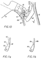
- FIG. 1 illustrates the clip applying instrument 10 of the present invention.
- Clip applying instrument 10 includes a handle portion 12 having a movable handle 14 and a stationary hand grip 16, which serves to operate a jaw mechanism 20 through the provision of an elongated body portion 18.
- the junction at which body portion 18 is joined to handle portion 12 includes a rotation collar 22 for varying the orientation of the jaw mechanism at the surgical site.
- Handle portion 12 further includes an aperture or window 24 which provides a visual indication of at least one position of the jaw members during a closing stroke of the handle portion.
- Fig. 2a illustrates the components of the handle portion 12 of instrument 10 of Fig. 1.
- the handle portion 12 includes a housing 12a and 12b within which the components of the handle portion are positioned.
- Rotation collar 22 includes a rotation ratchet mechanism 26 which provides for incremental rotation of rotation collar 22.
- a biasing spring 28 and a washer assembly 30 are provided to apply pressure to the ratchet mechanism 26.
- Rotation collar 22 is further described in detail with respect to the preferred embodiment of the rotation collar 22 as illustrated in Figs. 26 and 27 below.
- Movable handle 14 is secured to the housing halves by a pin 31 which permits rotation of movable handle 14 with respect to stationary hand grip 16.
- a handle spring 32 is provided to bias movable handle 14 to the open position, and movable handle 14 is connected through a series of linkages to effect loading of a clip into the jaw mechanism as well as crimping of a clip as will be described below.
- a pusher tube 52 and a channel tube 50 are provided in nested arrangement and are operatively connected to the movable handle 14 through channel tube links 34 and pusher tube links 36.
- a spring member 54 secures pusher tube 52 and channel tube 50 to each other, which are held in place by a C-clamp 56.
- Movable handle 14 further includes a pawl member 40 which is secured with a pawl spring 42 to the pawl housing 38 which is part of movable handle 14. As will be described below, pawl member 40 engages rack member 48 to provide for incremental closure of the movable handle 14, which in turn effects incremental closure of the jaw mechanism at the distal end of the instrument.
- a lever 44 is provided along with a latch plate 46 to coordinate the movements of pusher tube 52 and channel tube 50 with respect to the movable handle 14.
- channel tube 50 is operatively connected to a camming mechanism which includes a slidable channel to effect camming or closing of the jaw members to crimp a clip therebetween.
- Pusher tube 52 is operatively connected to a pusher bar mechanism which serves as the clip advancement means to advance a clip from the clip supply to the jaw mechanism. The operation of the handle mechanism with respect to the jaw mechanism will be discussed below.
- Fig. 2b illustrates the body portion 18 and jaw mechanism 20 of the instrument 10 of Fig. 1.
- Body portion 18 includes an upper housing half 58 and a lower housing half 86, within which are enclosed the operative elements of the body portion for advancing a clip to the jaw mechanism and for camming the jaw members closed to crimp a clip positioned therebetween.
- a pusher bar 60 is provided which is operatively connected at handle engagement means 85 to the pusher tube 52 illustrated in Fig. 2a.
- a clip feed spring 62 is provided for urging individual clips from the clip supply 70 through the provision of pin holder 66 and clip follower 68.
- a seal block 69 is provided toward the proximal end of upper housing half 58 and lower housing half 86 to obstruct the passage of gaseous media therethrough. Sealing block 69 preferably receives a sealing material, e.g., silicone grease, to improve its sealing function. As is known in the art, when all the clips have been delivered, clip follower 68 prevents further advancement of pusher bar 60 to give an indication to the surgeon that the instrument is no longer operative and has been emptied of its clips.
- a cover plate 72 is also provided to overlay the jaw mechanism 20 when the instrument is assembled to facilitate crimping of a clip positioned between the jaws.
- Jaw mechanism 20 which will be described in detail below, includes the jaw members 75, a tissue stop 78, a channel slide plate 80, and a camming channel 82 which is operatively connected at the handle engagement means 84 to the channel tube 50 discussed above with respect to Fig. 2a.
- a crimping bracket 76 is spot welded to the distal end of camming channel 82 to assist the camming of the jaw members 75 towards each other to crimp a clip positioned therebetween. The entire body portion is secured together with the assistance of C-clamp 88.
- FIG. 3 shows the instrument 10 in its initial position prior to the advancement of a clip to the jaw mechanism 20.
- the jaw mechanism is in its initial at-rest position in which the jaw members 75 are separated an initial distance D 1 where the jaw members 75 are in their clip receiving position.
- Pusher bar 60 is in its retracted position out of the vicinity of the jaw members 75, and behind a clip in anticipation of feeding the clip to the jaw mechanism 20.
- pusher tube 52 is in its fully retracted position awaiting slight movement of movable handle 14 to feed a clip to the jaw mechanism 20. Pusher tube 52 is held in the position shown in Fig.
- channel tube 50 is advanced through the provision of channel tube link 34, while pusher tube link 36 simultaneously moves pusher tube 52 in the direction towards the proximal end of the handle portion 12.
- channel tube 50 is fully advanced, thus moving camming channel 82 fully forward to cam the jaw members 75 closed to crimp clip 144 positioned therebetween.
- pusher tube 52 is moved to its proximalmost position, it has consequently withdrawn pusher bar 60 out of the jaw mechanism to the clip supply 70 to be in position to feed a subsequent clip to the jaw mechanism 20.
- pusher tube 52 is moved to the position shown in Fig.
- lever 44 is pivoted back into slot 53 to maintain pusher tube 52 in the position shown in Fig. 5.
- channel tube 50 returns to its initial position under the influence of channel tube link 34, while pusher tube 52 is maintained in a proximal position due to lever 44.
- the pusher bar 60 has not yet been advanced so that the jaws 75 are empty, awaiting a slight closing stroke of movable handle 14 to feed the next clip to the jaw mechanism 20.
- Figs. 7 and 8 illustrate the partial crimping feature of the present invention.
- a shunt or tube into a duct to introduce media to the duct, while at the same time maintaining the shunt in place. Accordingly, it becomes necessary to secure the shunt in place through the application of a clip, but it is necessary to prevent occlusion of the shunt through the provision of a partially closed clip.
- the surgeon's reliance on the endoscope to determine when a clip has been partially crimped introduces additional challenges.
- the surgical site is viewed on a video monitor, the field is somewhat distorted and it may be difficult to accurately determine when the clip is partially crimped about the duct or shunt.
- the closing mechanism for the instrument must ensure that the partially closed clip does not disengage from the instrument prior to securement on the duct or shunt.
- the mechanism of the present invention allows the surgeon to know when the jaw members are at a predetermined position indicating a partial closure of the clip for proper securement on the shunt and/or duct.
- Figs. 3-6 disclosed above After a clip has been fed to the jaw mechanism, the instrument is in the position as shown in Fig. 4 above. In this position, the jaw members 75 are separated by an initial distance D 1 which indicates the clip receiving position of the jaw mechanism 20.
- the pawl member 40 engages rack member 48 to provide for incremental closure of the handle mechanism, and consequently the jaw mechanism 20 as the surgeon continuously moves handle member 14 towards stationary hand grip 16.
- the rack member allows for a closing stroke as pawl member 40 passes over teeth 100 of rack member 48.
- the teeth 100 prevent movement of the handle in the opening direction, or away from stationary hand grip 16.
- the jaw mechanism slowly closes to crimp the clip 144 that is positioned between jaw members.
- pawl member 40 passes over teeth 100, the surgeon is provided with a tactile indication of the position of the jaw mechanism by feeling the clicks of the pawl member 40 over the teeth 100. The clicking also provides an audible indication of the position of the jaw members as they begin the crimping of the clip.
- the surgeon will know through the tactile indication of the cessation of the clicking of the pawl member 40 over the teeth 100, as well as the cessation of the audible clicking sound, that the jaw members are in the predetermined position having the distance D 2 between them corresponding to a partial crimping of the clip.
- the surgeon may effect a partial opening stroke of the handle member which will permit the clip 144 to be disengaged from the jaw mechanism 20.
- the opening stroke will of course be regulated by the distance of the space 104, since once the pawl member 40 re-engages the teeth 100, the opening stroke will no longer be permitted.
- the instrument After the clip has been released from the jaw mechanism in a partially closed manner over the duct, or the shunt that is positioned in the duct, the instrument must be reset to allow subsequent clip applications by completing the closing stroke so that the pawl member 40 passes through the space 104 and completely over the second set of teeth 102.
- teeth 102 still prevent pawl member 40 from traveling in a direction opposite arrow A, thus preventing an opening stroke of the movable handle 14. Accordingly, upon fully closing movable handle 14 to stationary hand grip 16, pawl member 40 engages blocking wall 106, which causes pawl member 40 to rotate in a clockwise direction with respect to Fig. 9. Rotation in the clockwise direction moves pawl detent 110 over handle detent 112 to the position shown in Fig. 10. When pawl detent 110 is in the position shown in Fig. 10 with respect to handle detent 112, the pawl member 40 is held in a position that fully disengages pawl member 40 from rack member 48.
- the present invention provides a window 24, preferably on either side of handle portion 12, which provides for a visual indication of the spacing between the jaws so the surgeon knows when the jaw members are in the predetermined position D 2 for the application of a partially closed clip.
- channel tube 50 includes a shroud portion 92 upon which is positioned a flag 94.
- channel tube 50 moves in the direction towards the distal end of the instrument through the provision of channel tube link 34.
- flag 94 appearing in the window 24 of the handle 12.
- the visual indicator flag 94 may be utilized with the audible and tactile indicators comprising the ratchet mechanism in the handle 12 described above. Once the surgeon sees the flag 94 in the window 24, he will know that the jaws are in the predetermined position D 2 and a partial opening stroke may be effected to release the partially closed clip 144 from the jaw mechanism 20. After the partially closed clip is released, the handle is fully closed to reset the instrument as described above.
- the visual indicator may be used by itself to provide the surgeon with a purely visual indication of the position of the jaw members.
- FIG. 24 and Figs. 25a-25b illustrate a further mechanism for providing indication to the surgeon of the predetermined distance D 2 for the application of a partially closed clip.
- a handle block member 180 for positioning in movable handle 14 as seen in Fig. 25a.
- Block 180 includes a flexible notch lock 182 and a handle engagement notch 184.
- a pivot pin 186 is provided, along with an eccentric pin slot 188.
- the entire mechanism is biased by a spring member 190.
- the block 180 is stored in a recess 200 of handle member 14.
- Spring 190 maintains block 180 in the recess 200 until the surgeon desires to move the block 180 into an armed position.
- the surgeon moves block 180 through the provision of finger notch 191 in the direction of arrow B to an armed position where notch lock 182 engages pin 202.
- the handle engagement notch 184 contacts stationary hand grip 16 as shown in Fig. 25b.
- the handle has closed a sufficient distance to close the jaw mechanism to the predetermined position so that the distance between the jaw members is equal to D 2 .
- the clip has been crimped sufficiently to partially close the clip about a duct or shunt.
- pin slot 188 has shifted with respect to pin 186, and in order to release handle block 180, the surgeon partially opens the handle mechanism so that a partial opening stroke of handle 14 is commenced. In this position, spring 190 returns block 180 into the recess 200 so that the block 180 is in the position shown in Fig. 25a. The handle may then be fully closed to reset the instrument for application of a subsequent clip.
- the handle block 180 may be utilized with the visual, audible, and tactile indicators as addressed above, or may be used by itself.
- an audible indicator comprising a small speaker or beeper 250 is provided in the stationary hand grip 16 and is associated with a battery pack 252 and a switch 254 having a spring contact arm 256 which is actuated by a shoulder 258 on the movable handle 14.
- the shoulder 258 on the movable handle 14 will have traveled to the position of engagement with the spring arm 256 of the switch 252 to close the switch contacts and create an audible sound through the beeper 250.
- activation means e.g., a toggle switch, may be associated with handle portion 12 to allow the surgeon to activate the electronic mechanism when it is desired to benefit from the audible indicator provided thereby.
- a similar arrangement is provided as that disclosed in Fig. 28.
- a small light bulb or LED 260 is provided within the handle 16 which will provide a visible indication of the position of the jaw mechanism with respect to the predetermined position D 2 .
- movement of the movable handle 14 towards the stationary handgrip 16 a sufficient distance will close the contacts of the switch 254 as the shoulder 258 of the movable handle 14 contacts the spring arm 256 of the switch 254.
- the light 260 will be illuminated, through the provision of the battery 252, and the surgeon will have a visual indication that the jaw mechanism is now in the predetermined position D 2 and that the partial opening stroke may be commenced to release the partially closed clip from the jaw mechanism.
- the embodiment of Fig. 29 may be utilized by itself, or in combination with the embodiment of Fig. 28, or any of the other position indicator embodiments described above.
- Figs. 11a-11d illustrate various embodiments of the rack member 48. Since it is desirable to ensure a partial closing stroke prior to the partial opening stroke to release the partially crimped clip, the first set of teeth 100 are provided to ensure the partial closing stroke as the pawl member 40 moves across rack member 48. As seen in Fig. 11a, the embodiment disclosed above, once the partial closing stroke is completed as the pawl member 40 passes over teeth 100, the space 104 provides a means for effecting the partial opening stroke to allow the partially closed clip to be released from the jaw mechanism. After release of the clip, teeth 100 prevent further opening of the handle mechanism, and requires the surgeon to fully close the instrument by ensuring that the pawl member 40 passes over second set of teeth 102. Fig.
- FIG. 11b illustrates an alternate embodiment of the rack member 48, and illustrates rack member 48a which includes teeth 100 and an elongate space 104.
- the opening stroke may be effected anywhere within space 104.
- the surgeon fully completes the closing stroke as the pawl member 40 passes over the space 104.
- Teeth 100 prevent a full opening stroke without the full closing stroke.
- Fig. 11c illustrates a further embodiment of rack member 48b where two rack members are positioned in series relation with respect to each other and the space 104 is actually the area between the two separate rack members 114 and 116.
- Rack 114 includes the first set of teeth 100 and rack 116 includes the second set of teeth 102.
- Fig. 11d illustrates a further embodiment of the rack mechanism of the present invention.
- Rack member 48 is provided with a parallel rack 118 which is positioned in parallel relationship.
- Rack member 118 includes a plurality of teeth 124 which are positioned adjacent space 104.
- parallel rack 118 includes spring arm 120 which provides for flexible movement of parallel rack 118 at its connection point 123 with rack 48.
- pawl member 40 passes over teeth 100 to ensure the partial closing stroke.
- a shoulder portion of the movable handle 14 (not shown), or a second pawl member (not shown) may engage teeth 124 to provide the surgeon with a tactile or audible indication that the jaw mechanism is in the predetermined position D 2 .
- the teeth 124 provide a different feel and different sound than that associated with the teeth 100 and 102 of rack 48.
- the flexibility of parallel rack 118 due to the spring arm 120 will provide the surgeon with a different feel to indicate that the jaw mechanism 20 is in the predetermined position D 2 .
- Fig. 12 there is illustrated the novel jaw mechanism of the present invention.
- jaw mechanisms are constructed from a single sheet of material in which the jaw structure is machined in an expensive and time-consuming process to form the individual jaw members 75.
- the present invention provides a pair of jaw members 126 and 128 which are constructed in mirror image and include a crimping region 130 and a mounting region 134.
- the individual jaw members 126 and 128 are secured together by a dovetail connection arrangement 132 which secures the two jaw members together and provide a mounting means 136 through the provision of spaces between the dove-tail portions.
- the present invention provides a simple and cost efficient means for constructing the jaw mechanism which is assembled prior to assembly on the instrument itself.
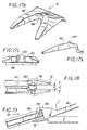
- Fig. 13 there is illustrated the novel tissue stop 78 of the present invention.
- Figs. 13-17 illustrate various embodiments of the tissue stop, which includes a vessel contacting region 138 which will contact a vessel, duct, or tissue in the event a clip is not positioned in the jaw mechanism.
- tissue stop 78 having clip stop 140 which provides a means for arresting the advancement of a clip from the clip advancing means to prevent the clip from being over-advanced to the jaw mechanism and insures the proper alignment of the clip once it is positioned in the jaws.
- Clip stop 140 includes a raised portion which will engage an inside surface of the clip, preferably at the bight portion, to properly align the clip within the jaws and prevent its over-advancement through the jaw mechanism.
- the tissue stop 78 of Fig. 13 also includes a jaw stop, which comprises a pair of raised arms which engage recesses in the underside of the jaw members 75 to prevent splaying of the jaw members, as will be described below with reference to Fig. 23.
- Figs. 14a-14c disclose an alternate embodiment of the tissue stop 78 which includes an upstanding hook member 150 which comprises the clip stop for arresting the advancement of the clip into the jaw mechanism.
- Clip member 150 engages at least an inside surface of the clip at the bight portion to prevent over-advancement of the clip into the jaw mechanism and properly align the clip with respect to the jaw members.
- Figs. 15a-15c illustrate a further embodiment of the clip stop assembly positioned on the tissue stop 78.
- a pair of detents 146 are provided which engage an inside surface of the clip in the region of the bight portion to arrest its advancement into the jaw mechanism.
- Figs. 16a-16c show a further embodiment of the clip stop positioned on the tissue stop 78, in which a pair of upstanding walls are provided for engaging at least the inside surface of the legs of the clip as it is advanced into the jaw mechanism.
- a further embodiment is disclosed in Figs. 17a-17c in which a contoured surface 152 is provided to properly align the clip in the jaw mechanism.
- a notch 153 is provided to engage the clip on the inside surface of the bight portion to slow the clip as it is advancing to the jaws.
- Fig. 18 there is illustrated the clip blocking mechanism associated with the jaw members 75 which prevents advancement of a clip into the jaws unless the jaws are fully opened in the clip receiving position, having a gap between them at a distance D 1 which is indicative of the clip receiving position.
- the jaw mechanism is shown in phantom in the fully opened, clip receiving position.
- a clip block member 156 is provided on each jaw member 75 which will engage the forward portion of the clip legs as the clip 144 is inserted into the partially closed jaws.
- distance D 3 is less than distance D 1 which indicates the clip receiving position.
- Fig. 19 illustrates the clip engaging feature of the pusher bar 60 of the present invention.
- clip 144 is cradled by pusher bar 60 at the cradle notch 158 as it is inserted into jaw mechanism 20.
- Cradle notch 158 includes a ramped forward portion 159 which facilitates removal of the pusher bar from the jaw assembly without pulling the clip 144 out of the jaw assembly 20.
- An alternate embodiment of the cradling means is illustrated in Figs. 20, 21 and 22. In Fig.
- clip engaging fingers 162 are pivotally secured to pusher 60 at pivot pin 160. This permits some play in the clip engaging fingers 162 to insure proper alignment of the clip 144 in the jaw mechanism 20.
- fingers 162 are constructed of a flexible plastic material which permits retraction of the pusher bar and fingers without dislodging the clip from the jaw mechanism.
- Fig. 21 illustrates a further cradling mechanism 164 which is secured to pusher bar 60 at clasp 166. It is contemplated that this embodiment can also be constructed of a flexible plastic material or a springy metal material, and may be permanently secured to pusher bar 60 or as a snap on feature when such a cradling mechanism 164 is desired.
- Fig. 21 illustrates a further cradling mechanism 164 which is secured to pusher bar 60 at clasp 166. It is contemplated that this embodiment can also be constructed of a flexible plastic material or a springy metal material, and may be permanently secured to pusher bar 60 or as a snap on feature when such a cradling mechanism
- cradling means 168 is preferably constructed of a spring metal material which is spot welded at weld 170 and includes a flexible notch portion 172 which cradles the clip 144 but permits retraction of the pusher bar 60 without dislodging the clip 144 from the jaw mechanism 20.
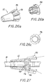
- Figs. 23a and 23b illustrate the jaw stop mechanism of the present invention.
- application of a clip over a previously applied clip is sometimes unavoidable.
- many times the jaw mechanism may be damaged in that the individual jaw members 75 splay outwardly a distance further than the initial clip receiving distance D 1 .
- a subsequently fed clip to the jaw mechanism may become disoriented or dislodged due to the overspacing between the jaws.
- the instrument of the present invention provides a jaw stop mechanism which includes jaw stop bracket 174 as seen in Fig.
- FIG. 23a which is part of tissue stop 78.
- This embodiment is similar to that shown above with respect to Figs. 13a-13c.
- the bracket engages recesses 176 in the underside of the jaw members, and prevents splaying of the jaws to a distance that is greater than D 1 .
- Fig. 23b illustrates a similar embodiment, in which bracket 178 is spot welded to tissue stop 78 instead of being integrally formed.
- Rotation collar 22 includes the collar 22, inner sleeve 194, and outer sleeve 196.
- inner sleeve 194 is positioned against body portion 18 and surrounded by outer sleeve 196, both of which are nested inside rotation collar 22.
- the plurality of planar surfaces which make up inner sleeve 194 cooperate with the plurality of planar surfaces 198 about the circumference of body portion 18 to provide for incremental rotation of the collar 22, and consequently the body portion 18, about a longitudinal axis of the instrument.
- Collar 22 includes a plurality of indentations 192 which have a scalloped cross-section and are dimensioned and configured to accommodate the finger tip of the surgeon.
- the scalloped walls 193 have a sufficient height to substantially enclose the volar surface, or the finger print portion of the distal most phalange of the index finger of the surgeon.
- the surgical clip applying instrument of the present invention provides a number of novel features which enhance the performance of the instrument during laparoscopic or endoscopic surgical procedures. Each of the features of the present invention simplify the operation of the instrument and substantially eliminates inadvertent misapplication of clips during the surgical procedure.
- the instrument provides a visible, audible, and tactile indication of the position of the jaw members during application of a clip, particularly during application of clips during such surgical procedures as gall bladder operations.
Description
- This invention relates to an apparatus for applying surgical clips to body tissue during laparoscopic or endoscopic procedures, and more particularly, to a surgical clip applier adapted to apply fully crimped clips as well as a partially formed clip during surgical procedures. Such apparatus is diclosed in US-A-5084057, in relation to which prior art, claim 1 below is differentiated.
- In laparoscopic and endoscopic surgical procedures, a small incision is made in the patient's body to provide access for a tube or cannula device. Once extended into the patient's body, the cannula provides an access port which allows insertion of various surgical instruments through the cannula for acting on organs, blood vessels, ducts, or body tissue far removed from the incision. Often during these procedures, it is necessary to apply hemostatic clips to blood vessels or various ducts to prevent the flow of body fluids therethrough during the procedure. Many times, the surgical procedure may necessitate the temporary implantation of shunts or tubes into ducts or vessels. Such procedures, such as gall bladder surgery, often require the placement of a shunt into the ducts during excision of the organ. To secure the shunt, a clip must be applied which is partially closed so as to avoid occluding the shunt. While instruments for performing surgical clip application are known in the art, none provide indication of the successful application of a partially crimped clip, such as is necessary to secure the shunt. Fully crimping a clip over a shunt will obviously occlude the shunt and defeat its purpose.
- One clip applier known well in the art is described in U.S. Patent No. 5,084,057, mentioned above. This instrument includes a mechanism for sequentially advancing a plurality of surgical clips towards a pair of distal jaw meters. Through actuation of handle structure, the jaw meters are closed to advantageously crimp the clip. The instrument does not provide an indication of the spacing between the jaws during the closing of the jaw members, other than through visual examination of the jaw members through an endoscope. Thus, when attempting to detachably secure a shunt to tissue, e.g., for cholangiography, it can be difficult to ascertain whether the jaw members have closed to an appropriate gap for securing the shunt.
- Furthermore, many instruments now incorporate ratchet mechanisms to prevent inadvertent opening of the handles and jaws until the clip is fully crimped, requiring a full closing stroke. Thus, the instruments are not designed to deliver a partially crimped clip.
- It has been common for clip appliers to rely on friction to capture a clip between the jaw members following advancement of the clip from the clip supply. Accordingly, the jaw members are constructed so as to have a gap between the crimping surface of each jaw member which is slightly less than the distance between the legs of a clip, so that the clip is slightly pinched between the jaws to hold the clip therein.
- Another method of maintaining the clip within the jaws is to machine the crimping surfaces of the jaw members to have a clip accepting slot. However, this increases cost and requires precision during the machining process to provide the proper dimensions for end use. The jaw members are typically a costly item since they are machined from a single piece to form the crimping surfaces.
- In view of this, it has been known to fabricate the jaw members separately, and then to assemble the jaw mechanism in the clip applying instrument. However, in instruments such as those disclosed in U.S. Patent Nos. 5,047,038; 4,246,903 and 4,228,895, the jaws are hinged at a pivot point and do not provide reliable securements and accurate camming.
- Should the jaw members be improperly gapped or aligned, the clip tends to fall out of the jaws, and potentially, into the patient's body. In addition, the clip advancement mechanism may not properly orient the clip if the jaws are not properly spaced. While some instruments may provide some clip alignment feature or clip stop mechanism, these are typically internal mechanisms which operate in conjunction with the clip supply, not the jaw mechanisms, such as disclosed in U.S. Patent Nos. 5,192,288 and 4,616,650. Finally, should the clip become dislodged, or slightly deviate off-line, there is no provision in the prior art for holding or guiding the clip into the jaws. While some instruments may provide tabs to align the clip at the clip supply, such as disclosed in U.S. Patent No. 4,492,262, there is no provision to support the clip outside the instrument at the jaws.
- It is also common, due to the restricted space at the surgical site in which the clip appliers are used, that at times a clip may be applied which is interfered with by a clip that has previously been applied, leading to a splaying of the jaws beyond the original gap between the jaw members. Depending on the strength of the jaw members, this may lead to an improper feeding of a subsequent clip to the jaws, resulting in potential instrument malfunction.
- It has been long known to provide instruments having a means for rotating the instrument with respect to its longitudinal orientation, typically through the provision of a rotation collar positioned at the juncture between the handle and elongated body portions of the instrument. Despite the multitude of prior art rotatable surgical instruments, a need exists to optimize the rotation collar to provide for more facile rotation capabilities.
- Those skilled in the surgical arts have recognized the need for a clip applicator which may be used in endoscopic or laparoscopic procedures such as gall bladder operations which is configured to partially close and release a clip to secure shunts during the procedure. In addition, a need exists for a clip applier which accurately advances and holds a clip in the jaw mechanism and which prevents splaying of the jaws in the event of a clip over clip application. An instrument is also needed which provides a visual indication of the position of the jaw mechanism, and may also provide an audible and tactile indication. An instrument is also needed which prevents feeding of a clip in the event the jaws are not fully opened, as well as an instrument which provides for facile rotation of the instrument's body portion.
- A novel clip applier of the present invention, as defined in claim 1 below, obviates the disadvantages encountered in the prior art and provides a cost-effective instrument which ensures accurate and efficient application of clips during a surgical procedure. The clip applier of the present invention provides an instrument which allows the surgeon to apply partially closed clips during a gall bladder operation to permit securement of shunts in organs without occluding the shunt, and provides visual, audible and/or tactile indication of when the jaws are in a predetermined position to permit the surgeon to release pressure on the handles to release the partially closed clip. The instrument of the present invention substantially reduces the possibility of clips inadvertently falling out of the jaws, and prevents splaying of the jaws beyond the initial clip-receiving gap between the crimping surfaces in the event a clip is applied over a previously applied clip. The instrument also prevents a clip from being fed to the jaws in the event the jaws are not fully opened, and includes a clip holding feature associated with the clip advancing mechanism to hold a clip to ensure correct positioning between the jaw members. The instrument also permits facile rotation of body portion with respect to its longitudinal orientation through the provision of a novel rotation collar.
- The present invention provides an apparatus for applying surgical clips to vessels and ducts in a patient which comprises a handle portion, a body portion which extends distally from the handle portion, a clip supply for storing a plurality of surgical clips in a position for sequential advancement towards a distal end of the body portion, a jaw mechanism disposed at the distal end of the body portion which is movable between an open position for receiving a clip and a closed position for forming a clip in response to movement of the handle portion, means for advancing a clip from the clip supply to the jaw mechanism and means which will affect a partial closure of a clip positioned in the jaw mechanism. The closing mechanism provides a means for affecting a closing stroke of the jaw mechanism from the open position to the closed position and includes means for permitting at least a partial opening stroke of the jaw mechanism after at least a partial closing stroke is completed. The instrument provides the surgeon with a means for crimping a clip partially and then opening the jaws a sufficient distance to release the partially closed clip. The closing mechanism of the instrument requires a full closing stroke of the handle mechanism prior to feeding a subsequent clip to the jaw mechanism. The present invention provides the surgeon with an apparatus which will allow him to apply surgical clips to ducts within the body and further provides a means for the temporary implantation of shunts or tubes in ducts by allowing partial closure of a clip without fully forming the clip to prevent occlusion of the duct or implanted shunt.
- The instrument provides a tactile indication of the position of the jaw mechanism so that the surgeon knows when the jaw mechanism has closed a sufficient distance to place the jaws in a predetermined zone or position in which the clip is partially closed for application to the duct or shunt at the surgical site. The instrument may further provide audible indication of the position of the jaws in the predetermined zone, and further may include visual indication means which will give the surgeon a visual indication of when the jaws are in the predetermined zone. The instrument allows the surgeon to partially open the handle mechanism to release pressure on the partially closed clip to allow the clip to be removed or released from the jaw mechanism. Upon release of the partially closed clip, the surgeon continues the closing stroke to reset the instrument to place it in a position for a subsequent use.
- The tactile and audible indicators essentially comprise a ratchet mechanism positioned within the handle portion of the clip applying instrument of the present invention. The ratchet mechanism includes a rack member positioned within the handle portion and a pawl member which is preferably positioned on the pivoting handle of the handle portion. The pawl member engages the rack member upon commencement of the closing stroke of the handle portion. Once the pawl member engages the rack, the movable handle is permitted to move in a closing direction towards the stationary hand grip, but is prevented from moving in an opening stroke away from the stationary hand grip. When the movable handle has travelled a sufficient distance, and the jaw mechanism has closed a corresponding sufficient distance so that a clip positioned between the jaw members is partially closed, the pawl member is released from the rack member, which allows the surgeon to effect a partial opening stroke of the movable handle, which provides a corresponding partial opening stroke of the jaw mechanism, and the partially closed clip is released from the jaw mechanism. The partial opening stroke of the handle portion will terminate when the pawl member re-engages the rack member and in order to reuse the instrument, the surgeon must complete the closing stroke of the movable handle of the handle portion.
- The rack and pawl assembly provides an audible indication of when the jaw members are in the proper zone to effect release of the partially closed clip. As the pawl travels over the rack, an audible clicking sound may be heard as the pawl passes over the teeth of the rack member. When the jaw members are in the proper position, i.e., the jaws are partially closed to partially close a clip position therebetween, the pawl member leaves the teeth of the rack member so that the clicking sound has ceased. Upon this audible indication, the surgeon will know that a partial opening stroke may be affected to release the clip positioned between the jaws. The pawl will then re-engage the rack member to terminate the opening stroke, and the surgeon knows that he must complete the closing stroke to reload the instrument. The pawl and rack mechanism also provides the surgeon with a tactile indication by allowing him to "feel" the instrument when it is in the predetermined zone for partial closure of a clip. As the surgeon moves the movable handle towards the stationary hand grip and the pawl passes over the teeth of the rack, the surgeon can feel the clicking of the pawl over the teeth of the rack. When the pawl leaves the rack, and the surgeon no longer feels the pawl passing over the teeth of the rack, he will know that the jaws are in the predetermined zone for partially closing a clip, and can release the force on the movable handle to effect a partial opening stroke of the movable handle and allow the partially closed clip to be released from the jaw mechanism.
- The ratchet mechanism disclosed in the handle portion preferably comprises a rack member having a plurality of teeth over a first distance and a plurality of teeth over a second distance which is separated by a space having no teeth. When the pawl member travels to the space having no teeth, the surgeon will know that the jaw mechanism is positioned within the predetermined zone for releasing the partially closed clip. Alternatively, the rack member may comprise a pair of rack members positioned in a series relationship which is separated by a distance. As the pawl member travels the distance between the two rack members, the surgeon will know that the jaw members are in the predetermined zone to release the partially closed clip. As a further alternative embodiment, the rack member may include teeth over a distance corresponding to a partial closing stroke so that once the pawl member passes the rack member, the surgeon will know that the jaw members are in the predetermined zone for releasing a partially closed clip. The rack member will ensure that the partial opening stroke which will release the partially closed clip will be terminated once the pawl member re-engages the rack member. The surgeon must then fully close the handle portion to reset the instrument to position a subsequent clip in the jaw mechanism for the next use.
- It is also contemplated that the ratchet mechanism include a pair of rack members positioned in parallel relationship, where the first rack includes teeth over at least a partial closing distance and does not provide teeth for a portion of the closing stroke which will allow the surgeon to partially open the handle portion to release a partially closed clip positioned in the jaw mechanism. The second rack member, positioned next to the first rack member will include teeth over the distance in which the first rack member is devoid of teeth. Preferably, the teeth of the second rack member are spaced differently from the teeth of the first rack member so that the surgeon knows from the audible indication of the change in rack members that the jaw mechanism is in the predetermined zone for effecting a partial opening stroke of the handle portion to release the clip which is partially closed in the jaw mechanism. In this embodiment, one or two pawl members may be provided, or when a single pawl member is provided, a portion of the movable handle may engage the second rack member to provide the audible indication of the predetermined zone of the jaw mechanism.
- The present invention also contemplates the provision of a visual indication for the surgeon, outside the patient's body, of the position of the jaw members, particularly when the jaw members are in the predetermined position or zone for partially closing a clip positioned between the jaw members. The visual indication may be provided on an instrument having the ratchet mechanism inside the handle. Moreover, the instrument may provide visible, audible and tactile indications of the position of the jaw mechanism. Within the handle portion, a first transmission means is provided for a linearly transferring motion from the movable handle to the clip advancing means, and a second transmission means for linearly transferring motion from the movable handle to the jaw closing means. The first transmission means which operates the clip advancement means comprises a pusher tube which is operatively connected to a pusher bar which extends the length of the instrument to push clips from the clip supply to the jaw mechanism. The second transmission means which operates the jaw closing means comprises a channel tube which is operatively connected to a sliding channel which extends the length of the body portion to effect opening and closing of the jaw members. In the preferred embodiment, an indicator or flag is provided on the channel tube which is visible through an aperture or window in the handle portion. When the instrument is at rest, such that the jaw members are fully opened to receive a clip therebetween, the flag on the channel tube is positioned within the handle away from the window or aperture. As the movable handle is moved through its closing stroke, the channel tube moves forward to urge the sliding channel forward to commence closing of the jaws and closure of a clip therebetween. Once the jaws have been closed a sufficient distance to effect a partial closure of the clip, the flag will appear in the aperture or window to indicate to the surgeon that a partial closure of the clip has been completed. At this point, the surgeon may commence a partial opening stroke of the handle portion to partially open the jaw mechanism to release the clip from between the jaw members. The visual indication may be used in conjunction with the ratchet mechanism described above, such that when the pawl member disengages from the rack member the flag will appear in the window to give the surgeon a visual, audible and tactile indication of the position of the jaw mechanism.
- In a further embodiment of the present invention, a clutch mechanism may be provided on the handle portion, in particular on the movable handle, which may be manually set to provide the surgeon with the jaw positioning feature. Preferably, a pivotable clutch block may be provided on the movable handle which is positionable between an armed and a disarmed position. In the disarmed position, the clutch block is hidden within the structure of the movable handle, and may be pivoted to the armed position when the surgeon desires to utilize the jaw positioning feature. Once pivoted to the armed position, the clutch block protrudes from the movable handle towards the stationary hand grip. As the surgeon begins the closing stroke, the movable handle moves towards the stationary hand grip and the jaw mechanism begins to close. Once the clutch block engages the stationary hand grip, the surgeon will no longer be able to close the two handles. At this point, the surgeon will know that the jaw members are positioned a distance corresponding to a partial closure of a clip positioned therebetween, and he will know that in order to release the clip from the jaw mechanism he must ease up on the force for closing the movable handle. As the surgeon eases the force, and a partial opening stroke is commenced, the clip is released from the jaw mechanism and the clutch block will automatically move from the armed position to the disarmed position, thus allowing the surgeon to complete the closing stroke. As stated with the embodiments described above, this clutch block feature may be utilized with the internal ratchet mechanism within the handle and/or the flag mechanism associated with the channel tube. Accordingly, the surgeon may have a visual, audible and/or tactile indication of the position of the jaw members during the surgical procedure.
- In an additional embodiment, an audible indicator in the form of a beeper may be provided to indicate the positioning of the jaw members with respect to the predetermined zone for partially crimping a clip. The stationary hand grip houses a small power cell such as a battery and the beeper itself. In addition, a small switch having a spring metal contact arm is provided to close the circuit and activate the beeper. As the pivoting handle is moved in the closing stroke, the beeper will sound when the jaws have been closed a sufficient distance to partially close the clip. The partial opening stroke will be completed when the beeper shuts off, indicating to the surgeon that the partially closed clip has been released and the complete closing stroke may be effected. It is also contemplated that a light or LED be provided in place of the beeper, although both the light and beeper may be provided together, providing the surgeon with the visible and audible indication of the jaw position.
- An additional feature of the present invention is the provision of a novel rotation collar which allows for facile rotation of the body portion and jaw mechanism during use of the instrument. As the surgeon grips the handle portion of the instrument, he may rotate the body portion using his index finger to move the rotation collar which couples the body portion to the handle portion. The rotation collar of the present invention includes an external surface having a plurality of scalloped portions into which the fingertip of the surgeon's index finger may comfortably fit. In particular, the scalloped portions are dimensioned and configured to accept the volar surface, or fingerprint portion, of the distalmost phalange of the surgeon's index finger. The raised walls of the individual scalloped portions provide comfortable seating for the tip of the finger of the surgeon to prevent slipping during rotation of the collar.
- The instrument of the present invention also includes a number of novel features which are associated with the jaw mechanism of the instrument. In particular, typical jaw mechanisms for surgical clip appliers provide a pair of jaw members which are machined from a single sheet of material and then secured to the distal end of the body portion of the instrument so that the jaw members may be flexed toward one another during closure of the instrument. The present invention provides a novel construction for the jaw mechanism in which the jaw members are constructed separately in mirror image so that the jaw members each include a clip crimping region and a mounting region. At the mounting region, there is provided a dovetail connection assembly to join the two jaw members together and a mounting means is also provided which includes a spacing between several of the dovetail joints which provides for mounting to the body portion of the instrument. Construction of the jaw members in accordance with this dovetail mounting feature allows the jaw members to be fabricated in simpler, more cost efficient manners, which eliminates the expensive machining process and increases the precision with which these jaw members are fabricated.
- The present invention also provides, adjacent the jaw mechanism, a tissue stop which will contact a vessel or duct in the event the clip is not positioned in the jaw mechanism. The tissue stop of the present invention also includes a clip stop provision which will arrest the forward advancement of the clip into the jaw mechanism by the clip advancement means to prevent a clip from being pushed too far into and through the jaw mechanism. The clip stop means may comprise a tab member which extends upwardly to engage an inside surface of the clip, or may also comprise, in an alternate embodiment, a raised wall which engages at least the inside surface of the clip member as it is inserted into the jaws.
- The present invention also provides a means for preventing splaying or over-opening of the jaw members, e.g., in the event that a clip is applied over a previously applied clip at the surgical site. The present invention provides a jaw stop mechanism which prevents the jaws from opening further than the at rest gap between the jaw members prior to the receipt of a clip. The jaw stop may comprise a bracket which surrounds the jaw members, or preferably, comprises a bracket having a pair of upstanding tabs which extend from the tissue stop member and engage into recesses provided in the jaw members to prevent the unwanted outward splaying of the jaws.
- The jaw members of the present invention also include a clip blocking means which prevents the advancement of a clip into the jaw mechanism in the event the jaws are not fully opened in the clip receiving position. The present invention provides the crimping region with a blocking wall which prevents advancement of a clip by engaging the leg portions of the clip in the event the jaws are not opened to their clip receiving position.
- The present invention also provides a means for accurately guiding a clip into the jaw mechanism from the clip supply. The clip advancing means in the present invention comprises a pusher bar which includes a cradling mechanism for holding and guiding a clip as it moves from the clip supply to the jaw mechanism. The cradling means engages at least an outside surface of the bight portion of the clip, which is the portion of the clip between the two legs. In one embodiment, the cradling means comprises a notch in the pusher bar whereby the pusher bar rides over the clip until the bight portion of the clip is engaged in the notch. Preferably, the notch includes a ramped forward portion which allows the pusher bar to move rearwardly off the clip so that the clip remains in the jaws after the pusher bar is retracted. In a second embodiment, the distalmost end of the pusher bar is provided with clip engaging fingers which may be integral with the pusher bar or which may be provided as a snap-on piece which will grasp and hold the clip as it is guided from the clip supply to the jaw mechanism. In a further embodiment, a single finger may pass over the bight portion of the clip, and since it is attached to or integral with the distalmost end of the pusher bar, guide the clip from the clip supply to the jaw mechanism.
- The foregoing features and further features of the present invention will become more readily apparent and may be understood by referring to the following detailed description of an illustrative embodiment of the clip applying instrument, taken in conjunction with the accompanying drawings, in which:
- Fig. 1 illustrates a perspective view of the clip applying instrument of the present invention;
- Fig. 2a illustrates an exploded perspective view of the handle portion of the instrument of Fig. 1;
- Fig. 2b illustrates an exploded perspective view of the body portion and jaw mechanism of the instrument of Fig. 1;
- Fig. 3 illustrates a side plan view in partial cutaway of the handle of the instrument of Fig. 1 in its initial, or at-rest, position;
- Fig. 4 illustrates a side plan view in partial cutaway of the handle of Fig. 3 in a position in which a clip is loaded into the jaw mechanism;
- Fig. 5 illustrates a side plan view in partial cutaway of the handle of the instrument of Fig. 1 in the clip crimping position;
- Fig. 6 illustrates a side plan view in partial cutaway of the handle of the instrument of Fig. 1 in the at-rest position after crimping of a clip and prior to subsequent feeding of a successive clip;
- Fig. 7 illustrates a side plan view in partial cutaway of the handle of the instrument of Fig. 1 in which the jaw mechanism is in a predetermined position indicative of a partial closing stroke to partially crimp a clip positioned in the jaws;
- Fig. 8 illustrates a top plan view of the handle of the instrument of Fig. 1 showing the visual indication of the predetermined position of the jaw mechanism of the embodiment of Fig. 7;
- Fig. 9 illustrates the ratchet mechanism of the present invention during a closing stroke of the handle mechanism;
- Fig. 10 illustrates the ratchet mechanism of the present invention during an opening stroke of the handle mechanism;
- Figs. 11a-11d illustrate the rack member of the ratchet mechanism of the present invention;
- Figs. 12a and 12b illustrate the jaw mechanism of the present invention;
- Figs. 13a-13c illustrate a first embodiment of the tissue stop of the present invention having a clip stop member and a jaw stop member positioned thereon;
- Figs. 14a-14c illustrate another embodiment of the tissue stop of the present invention having a clip stop positioned thereon;
- Figs. 15a-15c illustrate another embodiment of the tissue stop of the present invention having a clip stop positioned thereon;
- Figs. 16a-16c illustrate a further embodiment of the tissue stop of the present invention having a clip stop positioned thereon;
- Figs. 17a-17c illustrate a further embodiment of the tissue stop of the present invention having a clip stop positioned thereon;
- Fig. 18 illustrates the jaw mechanism of the present invention having a clip blocking member according to the present invention;
- Fig. 19 illustrates a first embodiment of the pusher bar of the present invention having a clip cradling means positioned thereon;
- Fig. 20 illustrates the pusher bar of the present invention having an alternate embodiment of the clip cradling means;
- Fig. 21 illustrates a further embodiment of the pusher bar having a clip cradling means;
- Fig. 22 illustrates the pusher bar of the present invention having a further embodiment of the clip cradling means positioned thereon;
- Figs. 23a and 23b illustrate the jaw stop mechanism of the present invention;
- Fig. 24 illustrates a plan view of the handle block mechanism;
- Figs. 25a and 25b illustrate a side plan view in partial cutaway of the movable handle of the present invention employing the handle block member of Fig. 24;
- Figs. 26a-26c illustrate the components of the rotation collar of the present invention;
- Fig. 27 illustrates a side cross-sectional view of the rotation collar of the present invention as it is positioned at the junction of the body portion and the handle portion;
- Fig. 28 illustrates a side plan view in cutaway of the handle mechanism of the present invention employing an audible indicator of the position of the jaw members in relation to a predetermined position; and
- Fig. 29 illustrates a side plan view in cutaway of the handle of the present invention employing a visual indication of the position of the jaw members in relation to a predetermined position.
-
- Referring now in specific detail to the drawings, in which like reference numerals identify similar or identical elements throughout the views, Fig. 1 illustrates the
clip applying instrument 10 of the present invention.Clip applying instrument 10 includes ahandle portion 12 having amovable handle 14 and astationary hand grip 16, which serves to operate ajaw mechanism 20 through the provision of anelongated body portion 18. The junction at whichbody portion 18 is joined to handleportion 12 includes arotation collar 22 for varying the orientation of the jaw mechanism at the surgical site.Handle portion 12 further includes an aperture orwindow 24 which provides a visual indication of at least one position of the jaw members during a closing stroke of the handle portion. These elements will be described in detail below. - Fig. 2a illustrates the components of the
handle portion 12 ofinstrument 10 of Fig. 1. Thehandle portion 12 includes ahousing 12a and 12b within which the components of the handle portion are positioned.Rotation collar 22 includes a rotation ratchet mechanism 26 which provides for incremental rotation ofrotation collar 22. A biasing spring 28 and awasher assembly 30 are provided to apply pressure to the ratchet mechanism 26.Rotation collar 22 is further described in detail with respect to the preferred embodiment of therotation collar 22 as illustrated in Figs. 26 and 27 below. -
Movable handle 14 is secured to the housing halves by apin 31 which permits rotation ofmovable handle 14 with respect tostationary hand grip 16. Ahandle spring 32 is provided to biasmovable handle 14 to the open position, andmovable handle 14 is connected through a series of linkages to effect loading of a clip into the jaw mechanism as well as crimping of a clip as will be described below. Apusher tube 52 and achannel tube 50 are provided in nested arrangement and are operatively connected to themovable handle 14 throughchannel tube links 34 and pusher tube links 36. Aspring member 54 securespusher tube 52 andchannel tube 50 to each other, which are held in place by a C-clamp 56. -
Movable handle 14 further includes apawl member 40 which is secured with apawl spring 42 to the pawl housing 38 which is part ofmovable handle 14. As will be described below,pawl member 40 engagesrack member 48 to provide for incremental closure of themovable handle 14, which in turn effects incremental closure of the jaw mechanism at the distal end of the instrument. Alever 44 is provided along with a latch plate 46 to coordinate the movements ofpusher tube 52 andchannel tube 50 with respect to themovable handle 14. - As will be described below,
channel tube 50 is operatively connected to a camming mechanism which includes a slidable channel to effect camming or closing of the jaw members to crimp a clip therebetween.Pusher tube 52 is operatively connected to a pusher bar mechanism which serves as the clip advancement means to advance a clip from the clip supply to the jaw mechanism. The operation of the handle mechanism with respect to the jaw mechanism will be discussed below. - Fig. 2b illustrates the
body portion 18 andjaw mechanism 20 of theinstrument 10 of Fig. 1.Body portion 18 includes anupper housing half 58 and alower housing half 86, within which are enclosed the operative elements of the body portion for advancing a clip to the jaw mechanism and for camming the jaw members closed to crimp a clip positioned therebetween. Apusher bar 60 is provided which is operatively connected at handle engagement means 85 to thepusher tube 52 illustrated in Fig. 2a. Aclip feed spring 62 is provided for urging individual clips from theclip supply 70 through the provision of pin holder 66 andclip follower 68. Aseal block 69 is provided toward the proximal end ofupper housing half 58 andlower housing half 86 to obstruct the passage of gaseous media therethrough. Sealingblock 69 preferably receives a sealing material, e.g., silicone grease, to improve its sealing function. As is known in the art, when all the clips have been delivered,clip follower 68 prevents further advancement ofpusher bar 60 to give an indication to the surgeon that the instrument is no longer operative and has been emptied of its clips. Acover plate 72 is also provided to overlay thejaw mechanism 20 when the instrument is assembled to facilitate crimping of a clip positioned between the jaws. -
Jaw mechanism 20, which will be described in detail below, includes thejaw members 75, atissue stop 78, achannel slide plate 80, and acamming channel 82 which is operatively connected at the handle engagement means 84 to thechannel tube 50 discussed above with respect to Fig. 2a. A crimpingbracket 76 is spot welded to the distal end ofcamming channel 82 to assist the camming of thejaw members 75 towards each other to crimp a clip positioned therebetween. The entire body portion is secured together with the assistance of C-clamp 88. - Turning now to Fig. 3, the operation of the handle mechanism of the
instrument 10 will be described. Fig. 3 shows theinstrument 10 in its initial position prior to the advancement of a clip to thejaw mechanism 20. As can be seen in Fig. 3, the jaw mechanism is in its initial at-rest position in which thejaw members 75 are separated an initial distance D1 where thejaw members 75 are in their clip receiving position.Pusher bar 60 is in its retracted position out of the vicinity of thejaw members 75, and behind a clip in anticipation of feeding the clip to thejaw mechanism 20. As can be seen in Fig. 3,pusher tube 52 is in its fully retracted position awaiting slight movement ofmovable handle 14 to feed a clip to thejaw mechanism 20.Pusher tube 52 is held in the position shown in Fig. 3 bypusher tube lever 44 which is engaged in aslot 53 inpusher tube 52.Lever 44 is maintained in this position untilmovable handle 14 is moved slightly in the direction ofstationary hand grip 16 so thatdetent 90 onlever 44 engages a corresponding detent on an end ofhandle 14 to effect a slight pivoting motion oflever 44 out ofslot 53, to permit advancement ofpusher tube 52 under the influence ofpusher tube spring 54 to the position shown in Fig. 4. As seen in Fig. 4,movable handle 14 is still substantially in the at-rest position, and in fact handlepawl member 40 has not yet engagedrack member 48. In this position,pusher tube 52 is fully advanced, thus moving thepusher bar 60 in a distal direction to advance aclip 144 to thejaw mechanism 20. - As seen in Fig. 5, as a full closing stroke of
movable handle 14 is effected towardsstationary hand grip 16,channel tube 50 is advanced through the provision ofchannel tube link 34, whilepusher tube link 36 simultaneously movespusher tube 52 in the direction towards the proximal end of thehandle portion 12. In the position shown in Fig. 5,channel tube 50 is fully advanced, thus movingcamming channel 82 fully forward to cam thejaw members 75 closed to crimpclip 144 positioned therebetween. Sincepusher tube 52 is moved to its proximalmost position, it has consequently withdrawnpusher bar 60 out of the jaw mechanism to theclip supply 70 to be in position to feed a subsequent clip to thejaw mechanism 20. However, aspusher tube 52 is moved to the position shown in Fig. 5,lever 44 is pivoted back intoslot 53 to maintainpusher tube 52 in the position shown in Fig. 5. As themovable handle 14 returns to its fully open position, as seen in Fig. 6,channel tube 50 returns to its initial position under the influence ofchannel tube link 34, whilepusher tube 52 is maintained in a proximal position due tolever 44. In this position, as seen in Fig. 6, thepusher bar 60 has not yet been advanced so that thejaws 75 are empty, awaiting a slight closing stroke ofmovable handle 14 to feed the next clip to thejaw mechanism 20. - Having thus described the operation of the internal components of the
handle portion 12, reference will be made to Figs. 7 and 8 which illustrate the partial crimping feature of the present invention. As discussed previously, it is often times desirable to provide a means for applying a partially closed clip during certain surgical procedures, in particular during a cholecystectomy procedure, more commonly known as gall bladder surgery. In such a procedure, it is sometimes necessary to place a shunt or tube into a duct to introduce media to the duct, while at the same time maintaining the shunt in place. Accordingly, it becomes necessary to secure the shunt in place through the application of a clip, but it is necessary to prevent occlusion of the shunt through the provision of a partially closed clip. Furthermore, since the cholecystectomy procedure has now gained increased popularity as an endoscopic procedure, the surgeon's reliance on the endoscope to determine when a clip has been partially crimped introduces additional challenges. Although the surgical site is viewed on a video monitor, the field is somewhat distorted and it may be difficult to accurately determine when the clip is partially crimped about the duct or shunt. In addition, the closing mechanism for the instrument must ensure that the partially closed clip does not disengage from the instrument prior to securement on the duct or shunt. - Turning now to Fig. 7, and with particular reference to Figs. 9 and 10, there is illustrated the mechanism of the present invention which provides for a partial closure of a clip for application to tissue, in particular a duct within the body to secure the duct or to place a shunt in the duct during the surgical procedure. The mechanism of the present invention allows the surgeon to know when the jaw members are at a predetermined position indicating a partial closure of the clip for proper securement on the shunt and/or duct. Reference is also made to Figs. 3-6 disclosed above. After a clip has been fed to the jaw mechanism, the instrument is in the position as shown in Fig. 4 above. In this position, the
jaw members 75 are separated by an initial distance D1 which indicates the clip receiving position of thejaw mechanism 20. As themovable handle 14 is moved towards thestationary hand grip 16, thepawl member 40 engagesrack member 48 to provide for incremental closure of the handle mechanism, and consequently thejaw mechanism 20 as the surgeon continuously moveshandle member 14 towardsstationary hand grip 16. As seen in Fig. 9, the rack member allows for a closing stroke aspawl member 40 passes overteeth 100 ofrack member 48. Theteeth 100 prevent movement of the handle in the opening direction, or away fromstationary hand grip 16. As thepawl member 40 is moved overteeth 100 in the direction of arrow A, the jaw mechanism slowly closes to crimp theclip 144 that is positioned between jaw members. Aspawl member 40 passes overteeth 100, the surgeon is provided with a tactile indication of the position of the jaw mechanism by feeling the clicks of thepawl member 40 over theteeth 100. The clicking also provides an audible indication of the position of the jaw members as they begin the crimping of the clip. - Once the
pawl member 40 reaches the position shown in Fig. 7, such that thepawl member 40 is positioned over thespace 104 between thefirst teeth 100 and thesecond teeth 102, the surgeon will know through the tactile indication of the cessation of the clicking of thepawl member 40 over theteeth 100, as well as the cessation of the audible clicking sound, that the jaw members are in the predetermined position having the distance D2 between them corresponding to a partial crimping of the clip. When thepawl member 40 is positioned overspace 104, the surgeon may effect a partial opening stroke of the handle member which will permit theclip 144 to be disengaged from thejaw mechanism 20. The opening stroke will of course be regulated by the distance of thespace 104, since once thepawl member 40 re-engages theteeth 100, the opening stroke will no longer be permitted. After the clip has been released from the jaw mechanism in a partially closed manner over the duct, or the shunt that is positioned in the duct, the instrument must be reset to allow subsequent clip applications by completing the closing stroke so that thepawl member 40 passes through thespace 104 and completely over the second set ofteeth 102. - Once the closing stroke is completed,
teeth 102 still preventpawl member 40 from traveling in a direction opposite arrow A, thus preventing an opening stroke of themovable handle 14. Accordingly, upon fully closingmovable handle 14 tostationary hand grip 16,pawl member 40 engages blockingwall 106, which causespawl member 40 to rotate in a clockwise direction with respect to Fig. 9. Rotation in the clockwise direction movespawl detent 110 overhandle detent 112 to the position shown in Fig. 10. Whenpawl detent 110 is in the position shown in Fig. 10 with respect to handledetent 112, thepawl member 40 is held in a position that fully disengagespawl member 40 fromrack member 48. This allows an opening stroke of the handle mechanism so that the handle may return to the position shown in Fig. 6 to await feeding and application of the next clip. Referring once again to Fig. 10, as the handle mechanism fully opens,boot portion 108 ofpawl member 40 will engage the wall ofstationary hand grip 16, which causespawl member 40 to rotatng described the audible and tactile indicators which allow the surgeon to determine when the jaw mechanism is in the predetermined position D2 for the application of a partially closed clip, reference is once again made to Fig. 7, along with Fig. 8, so that the visual indicator may now be described. As seen in Figs. 7 and 8, the present invention provides awindow 24, preferably on either side ofhandle portion 12, which provides for a visual indication of the spacing between the jaws so the surgeon knows when the jaw members are in the predetermined position D2 for the application of a partially closed clip. As can be seen in Fig. 7,channel tube 50 includes ashroud portion 92 upon which is positioned aflag 94. As thehandle member 14 is moved towardsstationary hand grip 16, as described above,channel tube 50 moves in the direction towards the distal end of the instrument through the provision ofchannel tube link 34. As the handle is closed,channel tube 50 moves forward withflag 94 appearing in thewindow 24 of thehandle 12. Once theflag 94 is visible in theindicator window 24, the surgeon knows thatjaw members 75 have been sufficiently closed to partially crimp aclip 144 positioned therebetween. It is contemplated that thevisual indicator flag 94 may be utilized with the audible and tactile indicators comprising the ratchet mechanism in thehandle 12 described above. Once the surgeon sees theflag 94 in thewindow 24, he will know that the jaws are in the predetermined position D2 and a partial opening stroke may be effected to release the partially closedclip 144 from thejaw mechanism 20. After the partially closed clip is released, the handle is fully closed to reset the instrument as described above. Of course, it is also contemplated that the visual indicator may be used by itself to provide the surgeon with a purely visual indication of the position of the jaw members. - Fig. 24 and Figs. 25a-25b illustrate a further mechanism for providing indication to the surgeon of the predetermined distance D2 for the application of a partially closed clip. In Fig. 24, there is shown a
handle block member 180 for positioning inmovable handle 14 as seen in Fig. 25a.Block 180 includes aflexible notch lock 182 and ahandle engagement notch 184. Apivot pin 186 is provided, along with aneccentric pin slot 188. The entire mechanism is biased by aspring member 190. Turning to Fig. 25a, theblock 180 is stored in arecess 200 ofhandle member 14.Spring 190 maintainsblock 180 in therecess 200 until the surgeon desires to move theblock 180 into an armed position. To do so, the surgeon movesblock 180 through the provision offinger notch 191 in the direction of arrow B to an armed position wherenotch lock 182 engagespin 202. As themovable handle 14 is moved towardstationary hand grip 16, thehandle engagement notch 184 contactsstationary hand grip 16 as shown in Fig. 25b. In this position, the handle has closed a sufficient distance to close the jaw mechanism to the predetermined position so that the distance between the jaw members is equal to D2. In this position, the clip has been crimped sufficiently to partially close the clip about a duct or shunt. When thehandle block 180 is in the position shown in Fig. 25b, it can be seen thatpin slot 188 has shifted with respect to pin 186, and in order to releasehandle block 180, the surgeon partially opens the handle mechanism so that a partial opening stroke ofhandle 14 is commenced. In this position,spring 190 returns block 180 into therecess 200 so that theblock 180 is in the position shown in Fig. 25a. The handle may then be fully closed to reset the instrument for application of a subsequent clip. As discussed above with the various indicator means, thehandle block 180 may be utilized with the visual, audible, and tactile indicators as addressed above, or may be used by itself. - Turning now to Figs. 28 and 29, alternate embodiments of the indicators are disclosed. In Fig. 28, an audible indicator comprising a small speaker or
beeper 250 is provided in thestationary hand grip 16 and is associated with abattery pack 252 and aswitch 254 having aspring contact arm 256 which is actuated by ashoulder 258 on themovable handle 14. As the handle is closed, and the jaw members reach the predetermined position D2 indicative of a partially closed clip, theshoulder 258 on themovable handle 14 will have traveled to the position of engagement with thespring arm 256 of theswitch 252 to close the switch contacts and create an audible sound through thebeeper 250. When the surgeon hears the beeper, thejaw members 75 will be in the predetermined position D2 and the surgeon will know to begin the partial opening stroke to release the partially closed clip. The partial opening stroke will be terminated when the beeper shuts off. The partially closed clip is then released, and the full closing stroke may be completed to reset the instrument. It is contemplated that activation means, e.g., a toggle switch, may be associated withhandle portion 12 to allow the surgeon to activate the electronic mechanism when it is desired to benefit from the audible indicator provided thereby. - With reference to Fig. 29, a similar arrangement is provided as that disclosed in Fig. 28. However, instead of a
beeper 250, a small light bulb orLED 260 is provided within thehandle 16 which will provide a visible indication of the position of the jaw mechanism with respect to the predetermined position D2. In this embodiment, movement of themovable handle 14 towards the stationary handgrip 16 a sufficient distance will close the contacts of theswitch 254 as theshoulder 258 of themovable handle 14 contacts thespring arm 256 of theswitch 254. Once the contacts are closed, the light 260 will be illuminated, through the provision of thebattery 252, and the surgeon will have a visual indication that the jaw mechanism is now in the predetermined position D2 and that the partial opening stroke may be commenced to release the partially closed clip from the jaw mechanism. Of course, it is contemplated that the embodiment of Fig. 29 may be utilized by itself, or in combination with the embodiment of Fig. 28, or any of the other position indicator embodiments described above. - Figs. 11a-11d illustrate various embodiments of the
rack member 48. Since it is desirable to ensure a partial closing stroke prior to the partial opening stroke to release the partially crimped clip, the first set ofteeth 100 are provided to ensure the partial closing stroke as thepawl member 40 moves acrossrack member 48. As seen in Fig. 11a, the embodiment disclosed above, once the partial closing stroke is completed as thepawl member 40 passes overteeth 100, thespace 104 provides a means for effecting the partial opening stroke to allow the partially closed clip to be released from the jaw mechanism. After release of the clip,teeth 100 prevent further opening of the handle mechanism, and requires the surgeon to fully close the instrument by ensuring that thepawl member 40 passes over second set ofteeth 102. Fig. 11b illustrates an alternate embodiment of therack member 48, and illustrates rack member 48a which includesteeth 100 and anelongate space 104. After thepawl member 40 passes overteeth 100, the opening stroke may be effected anywhere withinspace 104. After the clip that is partially closed has been released from thejaw mechanism 20, the surgeon fully completes the closing stroke as thepawl member 40 passes over thespace 104.Teeth 100 prevent a full opening stroke without the full closing stroke. Fig. 11c illustrates a further embodiment of rack member 48b where two rack members are positioned in series relation with respect to each other and thespace 104 is actually the area between the twoseparate rack members Rack 114 includes the first set ofteeth 100 andrack 116 includes the second set ofteeth 102. Once the partial closing stroke is completed as thepawl member 40 passes overteeth 100, the surgeon may effect the partial opening stroke as thepawl member 40 is positioned at the location of thespace 104 between the two rack members. The partial opening stroke will be completed when thepawl member 40 re-engagesteeth 100, and the surgeon must fully close the handle by passingpawl member 40 overteeth 102 to return the instrument to the set position for further use. Fig. 11d illustrates a further embodiment of the rack mechanism of the present invention.Rack member 48 is provided with aparallel rack 118 which is positioned in parallel relationship.Rack member 118 includes a plurality ofteeth 124 which are positionedadjacent space 104. It is contemplated in this arrangement thatparallel rack 118 includesspring arm 120 which provides for flexible movement ofparallel rack 118 at itsconnection point 123 withrack 48. As the handle mechanism is moved in a closing stroke,pawl member 40 passes overteeth 100 to ensure the partial closing stroke. Aspawl member 40 passes intospace 104, a shoulder portion of the movable handle 14 (not shown), or a second pawl member (not shown) may engageteeth 124 to provide the surgeon with a tactile or audible indication that the jaw mechanism is in the predetermined position D2. It is contemplated that theteeth 124 provide a different feel and different sound than that associated with theteeth rack 48. In addition, the flexibility ofparallel rack 118 due to thespring arm 120 will provide the surgeon with a different feel to indicate that thejaw mechanism 20 is in the predetermined position D2. - Turning now to Fig. 12, there is illustrated the novel jaw mechanism of the present invention. Typically, jaw mechanisms are constructed from a single sheet of material in which the jaw structure is machined in an expensive and time-consuming process to form the
individual jaw members 75. The present invention provides a pair ofjaw members region 130 and a mountingregion 134. Theindividual jaw members dovetail connection arrangement 132 which secures the two jaw members together and provide a mounting means 136 through the provision of spaces between the dove-tail portions. The present invention provides a simple and cost efficient means for constructing the jaw mechanism which is assembled prior to assembly on the instrument itself. - Turning now to Fig. 13, there is illustrated the novel tissue stop 78 of the present invention. Figs. 13-17 illustrate various embodiments of the tissue stop, which includes a
vessel contacting region 138 which will contact a vessel, duct, or tissue in the event a clip is not positioned in the jaw mechanism. In Fig. 13a-13c, there is illustratedtissue stop 78 having clip stop 140 which provides a means for arresting the advancement of a clip from the clip advancing means to prevent the clip from being over-advanced to the jaw mechanism and insures the proper alignment of the clip once it is positioned in the jaws.Clip stop 140 includes a raised portion which will engage an inside surface of the clip, preferably at the bight portion, to properly align the clip within the jaws and prevent its over-advancement through the jaw mechanism. Thetissue stop 78 of Fig. 13 also includes a jaw stop, which comprises a pair of raised arms which engage recesses in the underside of thejaw members 75 to prevent splaying of the jaw members, as will be described below with reference to Fig. 23. - Figs. 14a-14c disclose an alternate embodiment of the
tissue stop 78 which includes anupstanding hook member 150 which comprises the clip stop for arresting the advancement of the clip into the jaw mechanism.Clip member 150 engages at least an inside surface of the clip at the bight portion to prevent over-advancement of the clip into the jaw mechanism and properly align the clip with respect to the jaw members. - Figs. 15a-15c illustrate a further embodiment of the clip stop assembly positioned on the
tissue stop 78. In this embodiment, a pair ofdetents 146 are provided which engage an inside surface of the clip in the region of the bight portion to arrest its advancement into the jaw mechanism. - Figs. 16a-16c show a further embodiment of the clip stop positioned on the
tissue stop 78, in which a pair of upstanding walls are provided for engaging at least the inside surface of the legs of the clip as it is advanced into the jaw mechanism. A further embodiment is disclosed in Figs. 17a-17c in which acontoured surface 152 is provided to properly align the clip in the jaw mechanism. Anotch 153 is provided to engage the clip on the inside surface of the bight portion to slow the clip as it is advancing to the jaws. - Turning now to Fig. 18, there is illustrated the clip blocking mechanism associated with the
jaw members 75 which prevents advancement of a clip into the jaws unless the jaws are fully opened in the clip receiving position, having a gap between them at a distance D1 which is indicative of the clip receiving position. As seen in Fig. 18, the jaw mechanism is shown in phantom in the fully opened, clip receiving position. Aclip block member 156 is provided on eachjaw member 75 which will engage the forward portion of the clip legs as theclip 144 is inserted into the partially closed jaws. As indicated in Fig. 18, distance D3 is less than distance D1 which indicates the clip receiving position. - Fig. 19 illustrates the clip engaging feature of the
pusher bar 60 of the present invention. In order to prevent improper insertion of a clip into the jaw mechanism, it is desirable to provide a cradling mechanism to engage the clip and keep it in proper alignment as it is inserted into the jaws. As seen in Fig. 19,clip 144 is cradled bypusher bar 60 at thecradle notch 158 as it is inserted intojaw mechanism 20.Cradle notch 158 includes a rampedforward portion 159 which facilitates removal of the pusher bar from the jaw assembly without pulling theclip 144 out of thejaw assembly 20. An alternate embodiment of the cradling means is illustrated in Figs. 20, 21 and 22. In Fig. 20,clip engaging fingers 162 are pivotally secured topusher 60 atpivot pin 160. This permits some play in theclip engaging fingers 162 to insure proper alignment of theclip 144 in thejaw mechanism 20. Preferably,fingers 162 are constructed of a flexible plastic material which permits retraction of the pusher bar and fingers without dislodging the clip from the jaw mechanism. Fig. 21 illustrates afurther cradling mechanism 164 which is secured topusher bar 60 atclasp 166. It is contemplated that this embodiment can also be constructed of a flexible plastic material or a springy metal material, and may be permanently secured topusher bar 60 or as a snap on feature when such acradling mechanism 164 is desired. Fig. 22 shows a further embodiment of the cradling means 168, and is preferably constructed of a spring metal material which is spot welded atweld 170 and includes a flexible notch portion 172 which cradles theclip 144 but permits retraction of thepusher bar 60 without dislodging theclip 144 from thejaw mechanism 20. - Figs. 23a and 23b illustrate the jaw stop mechanism of the present invention. In certain surgical procedures utilizing surgical clip appliers, due to the cramped spacing inside the body during the endoscopic procedure, coupled with the sometimes distorted field of view through an endoscope or fiber optic system, application of a clip over a previously applied clip is sometimes unavoidable. When this occurs, many times the jaw mechanism may be damaged in that the
individual jaw members 75 splay outwardly a distance further than the initial clip receiving distance D1. When this occurs, a subsequently fed clip to the jaw mechanism may become disoriented or dislodged due to the overspacing between the jaws. In order to prevent this possibility, the instrument of the present invention provides a jaw stop mechanism which includesjaw stop bracket 174 as seen in Fig. 23a, which is part oftissue stop 78. This embodiment is similar to that shown above with respect to Figs. 13a-13c. The bracket engagesrecesses 176 in the underside of the jaw members, and prevents splaying of the jaws to a distance that is greater than D1. Fig. 23b illustrates a similar embodiment, in whichbracket 178 is spot welded to tissue stop 78 instead of being integrally formed. - Figs. 26 and 27 illustrate the rotation collar of the present invention.
Rotation collar 22 includes thecollar 22,inner sleeve 194, andouter sleeve 196. As can be seen in Fig. 27,inner sleeve 194 is positioned againstbody portion 18 and surrounded byouter sleeve 196, both of which are nested insiderotation collar 22. The plurality of planar surfaces which make upinner sleeve 194 cooperate with the plurality ofplanar surfaces 198 about the circumference ofbody portion 18 to provide for incremental rotation of thecollar 22, and consequently thebody portion 18, about a longitudinal axis of the instrument. -
Collar 22 includes a plurality ofindentations 192 which have a scalloped cross-section and are dimensioned and configured to accommodate the finger tip of the surgeon. The scallopedwalls 193 have a sufficient height to substantially enclose the volar surface, or the finger print portion of the distal most phalange of the index finger of the surgeon. By substantially enclosing the volar surface of the finger tip of the surgeon, slippage is substantially reduced and for all practical purposes eliminated, so that single finger rotation of the body portion, and consequently the jaw mechanism is provided for the surgeon. - The surgical clip applying instrument of the present invention provides a number of novel features which enhance the performance of the instrument during laparoscopic or endoscopic surgical procedures. Each of the features of the present invention simplify the operation of the instrument and substantially eliminates inadvertent misapplication of clips during the surgical procedure. The instrument provides a visible, audible, and tactile indication of the position of the jaw members during application of a clip, particularly during application of clips during such surgical procedures as gall bladder operations.
- The claims which follow identify embodiments of the invention additional to those described in detail above.
Claims (20)
- An apparatus (10) for applying surgical clips which includes a handle portion (12); a body portion (18) extending from said handle portion; a jaw mechanism (20) extending from said body portion at an end opposite said handle portion and movable between an open position for receiving a clip and a closed position for forming a clip in response to movement of said handle portion, such movement from the open to the closed position defining a closing stroke of the jaw mechanism; a clip supply (70) disposed within said body portion; and means (60) for advancing a clip from said clip supply to said jaw mechanism; said apparatus being characterized by:
a ratchet mechanism for completion of the closing stroke of said jaw mechanism, the ratchet mechanism (48, 40) permitting a partial opening stroke of said jaw mechanism after at least a partial closing stroke is effected, to permit release of a partially-formed clip from said jaw mechanism. - An apparatus according to Claim 1, wherein said ratchet mechanism is disposed within said handle portion, said ratchet mechanism including at least one rack member (48) and at least one pawl member (40).
- An apparatus according to Claim 2, wherein said rack member has a length which corresponds to a partial closing stroke of said jaw mechanism.
- An apparatus according to Claims 2 or 3, wherein said rack member (48) includes a plurality of teeth (100, 102) over a portion of a length of said rack member, a remaining portion (104) of said length of said rack member being devoid of teeth, such that said plurality of teeth permit incremental closure and said remaining portion of said rack member permits said partial opening stroke during said closing stroke.
- An apparatus according to claims 2, 3 or 4, wherein said ratchet mechanism includes at least two rack members (114, 116).
- An apparatus according to claim 5, wherein said rack members are arranged in a series relation having a space (104) therebetween, such that said pawl member engages and traverses a first (114) of said rack members, said space, and a second (116) of said rack member in sequence during the closing stroke.
- An apparatus according to claims 5 or 6, wherein said a partial opening stroke of said jaw mechanism is at least partially formed within said space between said rack members.
- An apparatus according to Claims 5, 6 or 7, wherein two side by side rack members (48, 118) include a plurality of teeth and are positioned in a parallel relationship, on of the rack members (48) having teeth over a portion of its length and a remaining portion of said length being devoid of teeth, and the other rack member (118) having teeth over its length.
- An apparatus according to Claim 8, wherein said first rack member is engaged by said pawl member, and said second rack member is engaged by a portion of said movable handle member (14).
- An apparatus according to any one of claims 2 to 9, wherein said pawl member includes means for maintaining said pawl member out of engagement with said rack member subsequent to a complete closing stroke to permit a complete opening stroke.
- An apparatus according to any one of the preceding claims, further comprising visual indicator means (24, 260) associated with a camming means for providing indication of a predetermined position of said jaw mechanism between said open position and said closed position.
- An apparatus according to any one of the preceding claims, wherein said jaw mechanism comprises a pair of jaw members (126, 128) and further comprising means (174) for engaging said jaw members to prevent said jaw members from being spaced apart from each other a distance which is greater than said gap defined by said jaw members in said open position.
- An apparatus according to claim 12, wherein said engaging means comprises a bracket (174) including a pair of tab members for engaging a portion of said jaw members to restrict splaying of said jaw members away from each other a distance greater than said gap.
- An apparatus according to any of the preceding claims, further comprising tissue stop means (78) disposed adjacent said jaw mechanism for aligning said jaw mechanism with respect to a vessel, said tissue stop means contacting said vessel only when said jaw mechansim is devoid of a clip.
- An apparatus according to Claim 14, further comprising means (150) disposed on said tissue stop means for arresting advancement of a clip into said jaw mechanism, said arresting means engaging at least an inside surface of said clip during advancement to said jaw mechanism to arrest advancement and align said clip within said jaw mechanism.
- An apparatus according to any one of the preceding claims, further comprising means (150) associated with said jaw mechanism for blocking advancement of a clip into said jaw mechanism unless said jaw mechanism is in said open position.
- An apparatus according to any of the preceding claims, further comprising cradling means (158, 162) associated with said advancing means (60) for engaging at least an outside surface of a clip during advancement of said clip to said jaw mechanism.
- An apparatus according to claim 17, wherein said advancing means comprises a pusher bar (60) and said cradling means comprises a notch (158) in a distal end of said pusher bar, said notch being dimensioned and configured to overlay and engage at least a bight portion of said clip during advancement of said clip.
- An apparatus according to claim 17, wherein said advancing means comprises a pusher bar and said cradling means comprises clip engaging fingers (162) depending from a distal end of said pusher bar, said fingers being dimensioned and configured to grasp at least a bight portion of said clip during advancement of said clip.
- An apparatus according to any of the preceding claims, further comprising collar means (22) for coupling said body portion to said handle portion, said collar means being rotatable about a longitudinal axis to effect rotation of said body portion about said longitudinal axis, an external surface of said collar means having finger engageable means (192) including a plurality of indentations dimensioned and configured to substantially enclose the volar surface of a distalmost phalange of an index finger of a user for effecting single finger rotation of said collar means and said body portion about said longitudinal axis.
Applications Claiming Priority (2)
| Application Number | Priority Date | Filing Date | Title |
|---|---|---|---|
| US134347 | 1993-10-08 | ||
| US08/134,347 US5607436A (en) | 1993-10-08 | 1993-10-08 | Apparatus for applying surgical clips |
Publications (3)
| Publication Number | Publication Date |
|---|---|
| EP0656190A2 EP0656190A2 (en) | 1995-06-07 |
| EP0656190A3 EP0656190A3 (en) | 1995-12-13 |
| EP0656190B1 true EP0656190B1 (en) | 2000-08-02 |
Family
ID=22462944
Family Applications (1)
| Application Number | Title | Priority Date | Filing Date |
|---|---|---|---|
| EP94115677A Expired - Lifetime EP0656190B1 (en) | 1993-10-08 | 1994-10-05 | Apparatus for applying surgical clips |
Country Status (5)
| Country | Link |
|---|---|
| US (3) | US5607436A (en) |
| EP (1) | EP0656190B1 (en) |
| CA (1) | CA2131973C (en) |
| DE (1) | DE69425417T2 (en) |
| ES (1) | ES2148263T3 (en) |
Families Citing this family (843)
| Publication number | Priority date | Publication date | Assignee | Title |
|---|---|---|---|---|
| US5582616A (en) * | 1994-08-05 | 1996-12-10 | Origin Medsystems, Inc. | Surgical helical fastener with applicator |
| US5803089A (en) | 1994-09-15 | 1998-09-08 | Visualization Technology, Inc. | Position tracking and imaging system for use in medical applications |
| US5700271A (en) | 1995-10-20 | 1997-12-23 | United States Surgical Corporation | Apparatus for applying surgical clips |
| DE29616632U1 (en) * | 1996-09-24 | 1996-11-28 | Aesculap Ag | Surgical application device for U-shaped clips |
| US5833696A (en) * | 1996-10-03 | 1998-11-10 | United States Surgical Corporation | Apparatus for applying surgical clips |
| US6099547A (en) * | 1997-02-13 | 2000-08-08 | Scimed Life Systems, Inc. | Method and apparatus for minimally invasive pelvic surgery |
| US6551328B2 (en) * | 1997-11-03 | 2003-04-22 | Symbiosis Corporation | Surgical instrument for invagination and fundoplication |
| US6660010B2 (en) * | 1998-01-27 | 2003-12-09 | Scimed Life Systems, Inc. | Bone anchor placement device with recessed anchor mount |
| US5976160A (en) * | 1998-03-31 | 1999-11-02 | Design Standards Corporation | Handle mechanism with two distinct pivot points |
| DE69916045T2 (en) | 1998-05-12 | 2004-08-05 | Boston Scientific Ltd., St. Michael | HAND-OPERATED BONE ANCHOR SETTING DEVICE |
| US6228098B1 (en) | 1998-07-10 | 2001-05-08 | General Surgical Innovations, Inc. | Apparatus and method for surgical fastening |
| US7364577B2 (en) | 2002-02-11 | 2008-04-29 | Sherwood Services Ag | Vessel sealing system |
| US6193732B1 (en) | 1999-01-08 | 2001-02-27 | Cardiothoracic System | Surgical clips and apparatus and method for clip placement |
| US9579091B2 (en) | 2000-01-05 | 2017-02-28 | Integrated Vascular Systems, Inc. | Closure system and methods of use |
| US7842068B2 (en) | 2000-12-07 | 2010-11-30 | Integrated Vascular Systems, Inc. | Apparatus and methods for providing tactile feedback while delivering a closure device |
| US8758400B2 (en) | 2000-01-05 | 2014-06-24 | Integrated Vascular Systems, Inc. | Closure system and methods of use |
| US6391048B1 (en) | 2000-01-05 | 2002-05-21 | Integrated Vascular Systems, Inc. | Integrated vascular device with puncture site closure component and sealant and methods of use |
| US6461364B1 (en) | 2000-01-05 | 2002-10-08 | Integrated Vascular Systems, Inc. | Vascular sheath with bioabsorbable puncture site closure apparatus and methods of use |
| WO2001056455A2 (en) | 2000-02-04 | 2001-08-09 | Imagyn Medical Technologies California, Inc. | Surgical clip applier |
| US6569171B2 (en) * | 2001-02-28 | 2003-05-27 | Microline, Inc. | Safety locking mechanism for a medical clip device |
| US6840945B2 (en) * | 2001-02-28 | 2005-01-11 | Microline, Inc. | Medical clip applier safety arrangement |
| US7141056B2 (en) * | 2000-02-15 | 2006-11-28 | Microline Pentax Inc. | Multiplier extension arrangement |
| IL135571A0 (en) * | 2000-04-10 | 2001-05-20 | Doron Adler | Minimal invasive surgery imaging system |
| AU8800801A (en) | 2000-09-08 | 2002-03-22 | James E Coleman | Surgical staple |
| US6626918B1 (en) | 2000-10-06 | 2003-09-30 | Medical Technology Group | Apparatus and methods for positioning a vascular sheath |
| US6599298B1 (en) | 2000-10-23 | 2003-07-29 | Vitalitec International, S.A. | Automatic surgical clip applier |
| US20020068945A1 (en) * | 2000-12-06 | 2002-06-06 | Robert Sixto | Surgical clips particularly useful in the endoluminal treatment of gastroesophageal reflux disease (GERD) |
| US7727246B2 (en) * | 2000-12-06 | 2010-06-01 | Ethicon Endo-Surgery, Inc. | Methods for endoluminal treatment |
| US7232445B2 (en) * | 2000-12-06 | 2007-06-19 | Id, Llc | Apparatus for the endoluminal treatment of gastroesophageal reflux disease (GERD) |
| US8062314B2 (en) * | 2000-12-06 | 2011-11-22 | Ethicon Endo-Surgery, Inc. | Methods for the endoluminal treatment of gastroesophageal reflux disease (GERD) |
| US6716226B2 (en) * | 2001-06-25 | 2004-04-06 | Inscope Development, Llc | Surgical clip |
| US20020138086A1 (en) * | 2000-12-06 | 2002-09-26 | Robert Sixto | Surgical clips particularly useful in the endoluminal treatment of gastroesophageal reflux disease (GERD) |
| US7211101B2 (en) | 2000-12-07 | 2007-05-01 | Abbott Vascular Devices | Methods for manufacturing a clip and clip |
| US6623510B2 (en) | 2000-12-07 | 2003-09-23 | Integrated Vascular Systems, Inc. | Closure device and methods for making and using them |
| US6695867B2 (en) | 2002-02-21 | 2004-02-24 | Integrated Vascular Systems, Inc. | Plunger apparatus and methods for delivering a closure device |
| US7905900B2 (en) | 2003-01-30 | 2011-03-15 | Integrated Vascular Systems, Inc. | Clip applier and methods of use |
| US7806904B2 (en) | 2000-12-07 | 2010-10-05 | Integrated Vascular Systems, Inc. | Closure device |
| US8690910B2 (en) | 2000-12-07 | 2014-04-08 | Integrated Vascular Systems, Inc. | Closure device and methods for making and using them |
| EP1365679B1 (en) * | 2001-03-09 | 2007-11-14 | Boston Scientific Limited | Medical slings |
| DE60121229T2 (en) | 2001-04-06 | 2007-05-24 | Sherwood Services Ag | DEVICE FOR SEALING AND SHARING A VESSEL WITH NON-LASTING END STOP |
| US6808491B2 (en) * | 2001-05-21 | 2004-10-26 | Syntheon, Llc | Methods and apparatus for on-endoscope instruments having end effectors and combinations of on-endoscope and through-endoscope instruments |
| IES20010547A2 (en) | 2001-06-07 | 2002-12-11 | Christy Cummins | Surgical Staple |
| US11229472B2 (en) | 2001-06-12 | 2022-01-25 | Cilag Gmbh International | Modular battery powered handheld surgical instrument with multiple magnetic position sensors |
| US6824547B2 (en) * | 2001-07-13 | 2004-11-30 | Pilling Weck Incorporated | Endoscopic clip applier and method |
| US7179265B2 (en) * | 2001-08-21 | 2007-02-20 | Microline Pentax, Inc. | Reduced diameter clip applying arrangement |
| US10285694B2 (en) | 2001-10-20 | 2019-05-14 | Covidien Lp | Surgical stapler with timer and feedback display |
| US7464847B2 (en) | 2005-06-03 | 2008-12-16 | Tyco Healthcare Group Lp | Surgical stapler with timer and feedback display |
| ES2360938T3 (en) * | 2002-04-17 | 2011-06-10 | Tyco Healthcare Group Lp | SEWING TOOL. |
| US7229452B2 (en) * | 2002-04-22 | 2007-06-12 | Tyco Healthcare Group Lp | Tack and tack applier |
| ES2335582T3 (en) * | 2002-04-29 | 2010-03-30 | Tyco Healthcare Group Lp | LIQUID CLIPS APPLICATOR. |
| JP2005525896A (en) * | 2002-05-16 | 2005-09-02 | シー2キュア インコーポレイティド | Small camera head |
| US7850709B2 (en) | 2002-06-04 | 2010-12-14 | Abbott Vascular Inc. | Blood vessel closure clip and delivery device |
| US7931649B2 (en) | 2002-10-04 | 2011-04-26 | Tyco Healthcare Group Lp | Vessel sealing instrument with electrical cutting mechanism |
| US7105004B2 (en) * | 2002-10-21 | 2006-09-12 | Start Llc | One-hand locking and releasing handheld medical instrument |
| US7799026B2 (en) | 2002-11-14 | 2010-09-21 | Covidien Ag | Compressible jaw configuration with bipolar RF output electrodes for soft tissue fusion |
| US7211092B2 (en) * | 2002-11-19 | 2007-05-01 | Pilling Weck Incorporated | Automated-feed surgical clip applier and related methods |
| US8758398B2 (en) | 2006-09-08 | 2014-06-24 | Integrated Vascular Systems, Inc. | Apparatus and method for delivering a closure element |
| US8905937B2 (en) | 2009-02-26 | 2014-12-09 | Integrated Vascular Systems, Inc. | Methods and apparatus for locating a surface of a body lumen |
| US8398656B2 (en) | 2003-01-30 | 2013-03-19 | Integrated Vascular Systems, Inc. | Clip applier and methods of use |
| US8821534B2 (en) | 2010-12-06 | 2014-09-02 | Integrated Vascular Systems, Inc. | Clip applier having improved hemostasis and methods of use |
| US7857828B2 (en) | 2003-01-30 | 2010-12-28 | Integrated Vascular Systems, Inc. | Clip applier and methods of use |
| US8202293B2 (en) | 2003-01-30 | 2012-06-19 | Integrated Vascular Systems, Inc. | Clip applier and methods of use |
| US20040193213A1 (en) * | 2003-03-11 | 2004-09-30 | Ernest Aranyi | Clip applying apparatus with curved jaws, and clip |
| EP1608272B1 (en) | 2003-03-11 | 2017-01-25 | Covidien LP | Clip applying apparatus with angled jaw |
| CA2523675C (en) | 2003-05-01 | 2016-04-26 | Sherwood Services Ag | Electrosurgical instrument which reduces thermal damage to adjacent tissue |
| US20070084897A1 (en) | 2003-05-20 | 2007-04-19 | Shelton Frederick E Iv | Articulating surgical stapling instrument incorporating a two-piece e-beam firing mechanism |
| US9060770B2 (en) | 2003-05-20 | 2015-06-23 | Ethicon Endo-Surgery, Inc. | Robotically-driven surgical instrument with E-beam driver |
| US7875040B2 (en) * | 2003-10-15 | 2011-01-25 | Femcare Limited | Visual indication of a trigger intermediate position on an applicator |
| AU2004283529B2 (en) * | 2003-10-15 | 2008-12-04 | Femcare Limited | Applicator |
| US9848938B2 (en) | 2003-11-13 | 2017-12-26 | Covidien Ag | Compressible jaw configuration with bipolar RF output electrodes for soft tissue fusion |
| US7367976B2 (en) | 2003-11-17 | 2008-05-06 | Sherwood Services Ag | Bipolar forceps having monopolar extension |
| US7131970B2 (en) | 2003-11-19 | 2006-11-07 | Sherwood Services Ag | Open vessel sealing instrument with cutting mechanism |
| US7585304B2 (en) * | 2004-02-02 | 2009-09-08 | Teleflex Medical Incorporated | Endoscopic clip applying apparatus with improved aperture for clip release and related method |
| US8182501B2 (en) | 2004-02-27 | 2012-05-22 | Ethicon Endo-Surgery, Inc. | Ultrasonic surgical shears and method for sealing a blood vessel using same |
| US7780662B2 (en) | 2004-03-02 | 2010-08-24 | Covidien Ag | Vessel sealing system using capacitive RF dielectric heating |
| US8517921B2 (en) * | 2004-04-16 | 2013-08-27 | Gyrus Acmi, Inc. | Endoscopic instrument having reduced diameter flexible shaft |
| US7621926B2 (en) * | 2004-04-16 | 2009-11-24 | Applied Medical Resources Corporation | Multi-fire surgical clip applier |
| IES20040368A2 (en) | 2004-05-25 | 2005-11-30 | James E Coleman | Surgical stapler |
| US11890012B2 (en) | 2004-07-28 | 2024-02-06 | Cilag Gmbh International | Staple cartridge comprising cartridge body and attached support |
| US8215531B2 (en) | 2004-07-28 | 2012-07-10 | Ethicon Endo-Surgery, Inc. | Surgical stapling instrument having a medical substance dispenser |
| WO2006034403A2 (en) | 2004-09-23 | 2006-03-30 | Tyco Healthcare Group, Lp | Clip applying apparatus and ligation clip |
| US8409222B2 (en) | 2004-10-08 | 2013-04-02 | Covidien Lp | Endoscopic surgical clip applier |
| US7819886B2 (en) * | 2004-10-08 | 2010-10-26 | Tyco Healthcare Group Lp | Endoscopic surgical clip applier |
| US9763668B2 (en) | 2004-10-08 | 2017-09-19 | Covidien Lp | Endoscopic surgical clip applier |
| JP5009159B2 (en) * | 2004-10-08 | 2012-08-22 | エシコン・エンド−サージェリィ・インコーポレイテッド | Ultrasonic surgical instrument |
| AU2005294178B2 (en) * | 2004-10-08 | 2009-06-11 | Covidien Lp | Apparatus for applying surgical clips |
| JP4833988B2 (en) | 2004-10-08 | 2011-12-07 | タイコ ヘルスケア グループ リミテッド パートナーシップ | Endoscopic surgical clip applier |
| NO322694B1 (en) * | 2004-12-29 | 2006-11-27 | Surgitech Norway As | Apparatus, especially for use in laparoscopic surgery |
| NO322695B1 (en) * | 2004-12-29 | 2006-11-27 | Surgitech Norway As | Instrument especially for use in laparoscopic surgical procedure |
| US7686804B2 (en) | 2005-01-14 | 2010-03-30 | Covidien Ag | Vessel sealer and divider with rotating sealer and cutter |
| US7909823B2 (en) | 2005-01-14 | 2011-03-22 | Covidien Ag | Open vessel sealing instrument |
| US20060184191A1 (en) | 2005-02-11 | 2006-08-17 | Boston Scientific Scimed, Inc. | Cutting balloon catheter having increased flexibility regions |
| US7740641B2 (en) * | 2005-04-14 | 2010-06-22 | Ethicon Endo-Surgery, Inc. | Clip applier with migrational resistance features |
| US7686820B2 (en) * | 2005-04-14 | 2010-03-30 | Ethicon Endo-Surgery, Inc. | Surgical clip applier ratchet mechanism |
| US7699860B2 (en) * | 2005-04-14 | 2010-04-20 | Ethicon Endo-Surgery, Inc. | Surgical clip |
| US20090014002A1 (en) * | 2005-04-14 | 2009-01-15 | Honeywell International Inc. | Air filter assembly |
| US7288098B2 (en) * | 2005-04-14 | 2007-10-30 | Ethicon Endo-Surgery, Inc. | Force limiting mechanism for medical instrument |
| US7297149B2 (en) | 2005-04-14 | 2007-11-20 | Ethicon Endo-Surgery, Inc. | Surgical clip applier methods |
| US8038686B2 (en) * | 2005-04-14 | 2011-10-18 | Ethicon Endo-Surgery, Inc. | Clip applier configured to prevent clip fallout |
| US7261724B2 (en) * | 2005-04-14 | 2007-08-28 | Ethicon Endo-Surgery, Inc. | Surgical clip advancement mechanism |
| US7731724B2 (en) * | 2005-04-14 | 2010-06-08 | Ethicon Endo-Surgery, Inc. | Surgical clip advancement and alignment mechanism |
| US8523882B2 (en) | 2005-04-14 | 2013-09-03 | Ethicon Endo-Surgery, Inc. | Clip advancer mechanism with alignment features |
| US8025668B2 (en) * | 2005-04-28 | 2011-09-27 | C. R. Bard, Inc. | Medical device removal system |
| US11291443B2 (en) | 2005-06-03 | 2022-04-05 | Covidien Lp | Surgical stapler with timer and feedback display |
| CA2609970C (en) | 2005-06-03 | 2014-08-12 | Tyco Healthcare Group Lp | Battery powered surgical instrument |
| US8926633B2 (en) | 2005-06-24 | 2015-01-06 | Abbott Laboratories | Apparatus and method for delivering a closure element |
| US8313497B2 (en) | 2005-07-01 | 2012-11-20 | Abbott Laboratories | Clip applier and methods of use |
| US8025621B2 (en) * | 2005-07-26 | 2011-09-27 | Microline Surgical, Inc. | Medical device with adjustable inner shaft movement |
| US8920442B2 (en) | 2005-08-24 | 2014-12-30 | Abbott Vascular Inc. | Vascular opening edge eversion methods and apparatuses |
| US9456811B2 (en) | 2005-08-24 | 2016-10-04 | Abbott Vascular Inc. | Vascular closure methods and apparatuses |
| US20070060895A1 (en) | 2005-08-24 | 2007-03-15 | Sibbitt Wilmer L Jr | Vascular closure methods and apparatuses |
| US7419495B2 (en) * | 2005-08-25 | 2008-09-02 | Microline Pentax Inc. | Trigger lockout device for clip applying instrument |
| US11484312B2 (en) | 2005-08-31 | 2022-11-01 | Cilag Gmbh International | Staple cartridge comprising a staple driver arrangement |
| US9237891B2 (en) | 2005-08-31 | 2016-01-19 | Ethicon Endo-Surgery, Inc. | Robotically-controlled surgical stapling devices that produce formed staples having different lengths |
| US7669746B2 (en) | 2005-08-31 | 2010-03-02 | Ethicon Endo-Surgery, Inc. | Staple cartridges for forming staples having differing formed staple heights |
| US11246590B2 (en) | 2005-08-31 | 2022-02-15 | Cilag Gmbh International | Staple cartridge including staple drivers having different unfired heights |
| US7934630B2 (en) | 2005-08-31 | 2011-05-03 | Ethicon Endo-Surgery, Inc. | Staple cartridges for forming staples having differing formed staple heights |
| US10159482B2 (en) | 2005-08-31 | 2018-12-25 | Ethicon Llc | Fastener cartridge assembly comprising a fixed anvil and different staple heights |
| US9326776B2 (en) * | 2005-09-29 | 2016-05-03 | Applied Medical Resources Corporation | Manually actuated surgical clip applier |
| CA2561034C (en) | 2005-09-30 | 2014-12-09 | Sherwood Services Ag | Flexible endoscopic catheter with an end effector for coagulating and transfecting tissue |
| US7722607B2 (en) | 2005-09-30 | 2010-05-25 | Covidien Ag | In-line vessel sealer and divider |
| US7922953B2 (en) | 2005-09-30 | 2011-04-12 | Covidien Ag | Method for manufacturing an end effector assembly |
| US7846161B2 (en) | 2005-09-30 | 2010-12-07 | Covidien Ag | Insulating boot for electrosurgical forceps |
| US7879035B2 (en) | 2005-09-30 | 2011-02-01 | Covidien Ag | Insulating boot for electrosurgical forceps |
| US20070191713A1 (en) | 2005-10-14 | 2007-08-16 | Eichmann Stephen E | Ultrasonic device for cutting and coagulating |
| US7738401B2 (en) * | 2005-10-20 | 2010-06-15 | At&T Intellectual Property I, L.P. | System and method for overlaying a hierarchical network design on a full mesh network |
| US20070089433A1 (en) * | 2005-10-20 | 2007-04-26 | Smurfit-Stone Container Enterprises, Inc. | Methods and systems for monitoring a shelf life of a product stored within a container |
| US20070106317A1 (en) | 2005-11-09 | 2007-05-10 | Shelton Frederick E Iv | Hydraulically and electrically actuated articulation joints for surgical instruments |
| US20070162030A1 (en) * | 2006-01-06 | 2007-07-12 | Ernest Aranyi | Multi-pronged compressive absorbable tack |
| US7621930B2 (en) | 2006-01-20 | 2009-11-24 | Ethicon Endo-Surgery, Inc. | Ultrasound medical instrument having a medical ultrasonic blade |
| US20070173866A1 (en) * | 2006-01-23 | 2007-07-26 | Tyco Healthcare Group, Lp | Surgical hemostatic clip |
| US11278279B2 (en) | 2006-01-31 | 2022-03-22 | Cilag Gmbh International | Surgical instrument assembly |
| US20110024477A1 (en) | 2009-02-06 | 2011-02-03 | Hall Steven G | Driven Surgical Stapler Improvements |
| US20120292367A1 (en) | 2006-01-31 | 2012-11-22 | Ethicon Endo-Surgery, Inc. | Robotically-controlled end effector |
| US7845537B2 (en) | 2006-01-31 | 2010-12-07 | Ethicon Endo-Surgery, Inc. | Surgical instrument having recording capabilities |
| US8820603B2 (en) | 2006-01-31 | 2014-09-02 | Ethicon Endo-Surgery, Inc. | Accessing data stored in a memory of a surgical instrument |
| US20110290856A1 (en) | 2006-01-31 | 2011-12-01 | Ethicon Endo-Surgery, Inc. | Robotically-controlled surgical instrument with force-feedback capabilities |
| US11224427B2 (en) | 2006-01-31 | 2022-01-18 | Cilag Gmbh International | Surgical stapling system including a console and retraction assembly |
| US8186555B2 (en) | 2006-01-31 | 2012-05-29 | Ethicon Endo-Surgery, Inc. | Motor-driven surgical cutting and fastening instrument with mechanical closure system |
| US7753904B2 (en) | 2006-01-31 | 2010-07-13 | Ethicon Endo-Surgery, Inc. | Endoscopic surgical instrument with a handle that can articulate with respect to the shaft |
| US8708213B2 (en) | 2006-01-31 | 2014-04-29 | Ethicon Endo-Surgery, Inc. | Surgical instrument having a feedback system |
| US11793518B2 (en) | 2006-01-31 | 2023-10-24 | Cilag Gmbh International | Powered surgical instruments with firing system lockout arrangements |
| DE102006007107B4 (en) * | 2006-02-16 | 2007-10-18 | Peter Lazic Gmbh | Pipe tongs with power transmission |
| US8992422B2 (en) | 2006-03-23 | 2015-03-31 | Ethicon Endo-Surgery, Inc. | Robotically-controlled endoscopic accessory channel |
| USD629101S1 (en) | 2006-03-24 | 2010-12-14 | Tyco Healthcare Group Lp | Surgical clip applier |
| USD625009S1 (en) | 2006-03-24 | 2010-10-05 | Tyco Healthcare Group Lp | Surgical clip applier |
| US8808310B2 (en) * | 2006-04-20 | 2014-08-19 | Integrated Vascular Systems, Inc. | Resettable clip applier and reset tools |
| EP2015681B1 (en) | 2006-05-03 | 2018-03-28 | Datascope Corp. | Tissue closure device |
| US8322455B2 (en) | 2006-06-27 | 2012-12-04 | Ethicon Endo-Surgery, Inc. | Manually driven surgical cutting and fastening instrument |
| US8556930B2 (en) | 2006-06-28 | 2013-10-15 | Abbott Laboratories | Vessel closure device |
| US10568652B2 (en) | 2006-09-29 | 2020-02-25 | Ethicon Llc | Surgical staples having attached drivers of different heights and stapling instruments for deploying the same |
| EP2314232B1 (en) | 2006-10-17 | 2015-03-25 | Covidien LP | Apparatus for applying surgical clips |
| US8684253B2 (en) | 2007-01-10 | 2014-04-01 | Ethicon Endo-Surgery, Inc. | Surgical instrument with wireless communication between a control unit of a robotic system and remote sensor |
| US11291441B2 (en) | 2007-01-10 | 2022-04-05 | Cilag Gmbh International | Surgical instrument with wireless communication between control unit and remote sensor |
| US8652120B2 (en) | 2007-01-10 | 2014-02-18 | Ethicon Endo-Surgery, Inc. | Surgical instrument with wireless communication between control unit and sensor transponders |
| US11039836B2 (en) | 2007-01-11 | 2021-06-22 | Cilag Gmbh International | Staple cartridge for use with a surgical stapling instrument |
| US8540128B2 (en) | 2007-01-11 | 2013-09-24 | Ethicon Endo-Surgery, Inc. | Surgical stapling device with a curved end effector |
| JP2008192187A (en) * | 2007-01-31 | 2008-08-21 | Fujitsu Ltd | Head controller, memory device, and contact detection method |
| US7473258B2 (en) * | 2007-03-08 | 2009-01-06 | Cardica, Inc. | Surgical stapler |
| US7533790B1 (en) * | 2007-03-08 | 2009-05-19 | Cardica, Inc. | Surgical stapler |
| US7431188B1 (en) | 2007-03-15 | 2008-10-07 | Tyco Healthcare Group Lp | Surgical stapling apparatus with powered articulation |
| US8727197B2 (en) | 2007-03-15 | 2014-05-20 | Ethicon Endo-Surgery, Inc. | Staple cartridge cavity configuration with cooperative surgical staple |
| US8911460B2 (en) | 2007-03-22 | 2014-12-16 | Ethicon Endo-Surgery, Inc. | Ultrasonic surgical instruments |
| US8142461B2 (en) | 2007-03-22 | 2012-03-27 | Ethicon Endo-Surgery, Inc. | Surgical instruments |
| US8226675B2 (en) * | 2007-03-22 | 2012-07-24 | Ethicon Endo-Surgery, Inc. | Surgical instruments |
| US8057498B2 (en) | 2007-11-30 | 2011-11-15 | Ethicon Endo-Surgery, Inc. | Ultrasonic surgical instrument blades |
| US20080234709A1 (en) | 2007-03-22 | 2008-09-25 | Houser Kevin L | Ultrasonic surgical instrument and cartilage and bone shaping blades therefor |
| CN102327138B (en) | 2007-03-26 | 2014-09-10 | 柯惠Lp公司 | Endoscopic surgical clip applier |
| WO2008127968A2 (en) | 2007-04-11 | 2008-10-23 | Tyco Healthcare Group Lp | Surgical clip applier |
| US8800837B2 (en) | 2007-04-13 | 2014-08-12 | Covidien Lp | Powered surgical instrument |
| US7950560B2 (en) | 2007-04-13 | 2011-05-31 | Tyco Healthcare Group Lp | Powered surgical instrument |
| US20080255413A1 (en) | 2007-04-13 | 2008-10-16 | Michael Zemlok | Powered surgical instrument |
| US11259801B2 (en) | 2007-04-13 | 2022-03-01 | Covidien Lp | Powered surgical instrument |
| US7823760B2 (en) | 2007-05-01 | 2010-11-02 | Tyco Healthcare Group Lp | Powered surgical stapling device platform |
| US20080277445A1 (en) * | 2007-05-07 | 2008-11-13 | Zergiebel Earl M | Single fire tacker instrument |
| US7931660B2 (en) | 2007-05-10 | 2011-04-26 | Tyco Healthcare Group Lp | Powered tacker instrument |
| US8931682B2 (en) | 2007-06-04 | 2015-01-13 | Ethicon Endo-Surgery, Inc. | Robotically-controlled shaft based rotary drive systems for surgical instruments |
| US11857181B2 (en) | 2007-06-04 | 2024-01-02 | Cilag Gmbh International | Robotically-controlled shaft based rotary drive systems for surgical instruments |
| US20080312649A1 (en) * | 2007-06-18 | 2008-12-18 | Paul Guerra | Illuminated instrument buttons |
| US7753245B2 (en) | 2007-06-22 | 2010-07-13 | Ethicon Endo-Surgery, Inc. | Surgical stapling instruments |
| US8226681B2 (en) | 2007-06-25 | 2012-07-24 | Abbott Laboratories | Methods, devices, and apparatus for managing access through tissue |
| US11849941B2 (en) | 2007-06-29 | 2023-12-26 | Cilag Gmbh International | Staple cartridge having staple cavities extending at a transverse angle relative to a longitudinal cartridge axis |
| JP2009045428A (en) | 2007-07-25 | 2009-03-05 | Terumo Corp | Operating mechanism, medical manipulator and surgical robot system |
| US8808319B2 (en) | 2007-07-27 | 2014-08-19 | Ethicon Endo-Surgery, Inc. | Surgical instruments |
| US8257377B2 (en) * | 2007-07-27 | 2012-09-04 | Ethicon Endo-Surgery, Inc. | Multiple end effectors ultrasonic surgical instruments |
| US8523889B2 (en) | 2007-07-27 | 2013-09-03 | Ethicon Endo-Surgery, Inc. | Ultrasonic end effectors with increased active length |
| US8882791B2 (en) | 2007-07-27 | 2014-11-11 | Ethicon Endo-Surgery, Inc. | Ultrasonic surgical instruments |
| US8348967B2 (en) * | 2007-07-27 | 2013-01-08 | Ethicon Endo-Surgery, Inc. | Ultrasonic surgical instruments |
| US9044261B2 (en) | 2007-07-31 | 2015-06-02 | Ethicon Endo-Surgery, Inc. | Temperature controlled ultrasonic surgical instruments |
| US8430898B2 (en) | 2007-07-31 | 2013-04-30 | Ethicon Endo-Surgery, Inc. | Ultrasonic surgical instruments |
| US8252012B2 (en) | 2007-07-31 | 2012-08-28 | Ethicon Endo-Surgery, Inc. | Ultrasonic surgical instrument with modulator |
| US8512365B2 (en) | 2007-07-31 | 2013-08-20 | Ethicon Endo-Surgery, Inc. | Surgical instruments |
| US8623027B2 (en) | 2007-10-05 | 2014-01-07 | Ethicon Endo-Surgery, Inc. | Ergonomic surgical instruments |
| USD594983S1 (en) | 2007-10-05 | 2009-06-23 | Ethicon Endo-Surgery, Inc. | Handle assembly for surgical instrument |
| US7922063B2 (en) | 2007-10-31 | 2011-04-12 | Tyco Healthcare Group, Lp | Powered surgical instrument |
| US10010339B2 (en) | 2007-11-30 | 2018-07-03 | Ethicon Llc | Ultrasonic surgical blades |
| US7901423B2 (en) | 2007-11-30 | 2011-03-08 | Ethicon Endo-Surgery, Inc. | Folded ultrasonic end effectors with increased active length |
| US8893947B2 (en) | 2007-12-17 | 2014-11-25 | Abbott Laboratories | Clip applier and methods of use |
| US20090157101A1 (en) | 2007-12-17 | 2009-06-18 | Abbott Laboratories | Tissue closure system and methods of use |
| US7841502B2 (en) | 2007-12-18 | 2010-11-30 | Abbott Laboratories | Modular clip applier |
| US7866527B2 (en) | 2008-02-14 | 2011-01-11 | Ethicon Endo-Surgery, Inc. | Surgical stapling apparatus with interlockable firing system |
| US9179912B2 (en) | 2008-02-14 | 2015-11-10 | Ethicon Endo-Surgery, Inc. | Robotically-controlled motorized surgical cutting and fastening instrument |
| BRPI0901282A2 (en) | 2008-02-14 | 2009-11-17 | Ethicon Endo Surgery Inc | surgical cutting and fixation instrument with rf electrodes |
| US8636736B2 (en) | 2008-02-14 | 2014-01-28 | Ethicon Endo-Surgery, Inc. | Motorized surgical cutting and fastening instrument |
| US7819298B2 (en) | 2008-02-14 | 2010-10-26 | Ethicon Endo-Surgery, Inc. | Surgical stapling apparatus with control features operable with one hand |
| US9770245B2 (en) | 2008-02-15 | 2017-09-26 | Ethicon Llc | Layer arrangements for surgical staple cartridges |
| US8733611B2 (en) * | 2008-03-12 | 2014-05-27 | Covidien Lp | Ratcheting mechanism for surgical stapling device |
| US8021375B2 (en) * | 2008-04-21 | 2011-09-20 | Conmed Corporation | Surgical clip applicator |
| US9282965B2 (en) | 2008-05-16 | 2016-03-15 | Abbott Laboratories | Apparatus and methods for engaging tissue |
| US8058771B2 (en) | 2008-08-06 | 2011-11-15 | Ethicon Endo-Surgery, Inc. | Ultrasonic device for cutting and coagulating with stepped output |
| US9089360B2 (en) | 2008-08-06 | 2015-07-28 | Ethicon Endo-Surgery, Inc. | Devices and techniques for cutting and coagulating tissue |
| US8056565B2 (en) | 2008-08-25 | 2011-11-15 | Tyco Healthcare Group Lp | Surgical clip applier and method of assembly |
| US8465502B2 (en) | 2008-08-25 | 2013-06-18 | Covidien Lp | Surgical clip applier and method of assembly |
| US20110208212A1 (en) | 2010-02-19 | 2011-08-25 | Zergiebel Earl M | Surgical clip applier |
| US8585717B2 (en) | 2008-08-29 | 2013-11-19 | Covidien Lp | Single stroke endoscopic surgical clip applier |
| US9358015B2 (en) | 2008-08-29 | 2016-06-07 | Covidien Lp | Endoscopic surgical clip applier with wedge plate |
| US8267944B2 (en) | 2008-08-29 | 2012-09-18 | Tyco Healthcare Group Lp | Endoscopic surgical clip applier with lock out |
| EP2543324B1 (en) | 2008-08-29 | 2015-10-21 | Covidien LP | Endoscopic clip applier |
| US8409223B2 (en) | 2008-08-29 | 2013-04-02 | Covidien Lp | Endoscopic surgical clip applier with clip retention |
| US8113405B2 (en) * | 2008-09-03 | 2012-02-14 | Tyco Healthcare Group, Lp | Surgical instrument with indicator |
| US20100051668A1 (en) * | 2008-09-03 | 2010-03-04 | Milliman Keith L | Surgical instrument with indicator |
| US20100057118A1 (en) * | 2008-09-03 | 2010-03-04 | Dietz Timothy G | Ultrasonic surgical blade |
| US11648005B2 (en) | 2008-09-23 | 2023-05-16 | Cilag Gmbh International | Robotically-controlled motorized surgical instrument with an end effector |
| US8210411B2 (en) | 2008-09-23 | 2012-07-03 | Ethicon Endo-Surgery, Inc. | Motor-driven surgical cutting instrument |
| US9005230B2 (en) | 2008-09-23 | 2015-04-14 | Ethicon Endo-Surgery, Inc. | Motorized surgical instrument |
| US9386983B2 (en) | 2008-09-23 | 2016-07-12 | Ethicon Endo-Surgery, Llc | Robotically-controlled motorized surgical instrument |
| US8142473B2 (en) | 2008-10-03 | 2012-03-27 | Tyco Healthcare Group Lp | Method of transferring rotational motion in an articulating surgical instrument |
| US8016827B2 (en) | 2008-10-09 | 2011-09-13 | Tyco Healthcare Group Lp | Apparatus, system, and method for performing an electrosurgical procedure |
| US8608045B2 (en) | 2008-10-10 | 2013-12-17 | Ethicon Endo-Sugery, Inc. | Powered surgical cutting and stapling apparatus with manually retractable firing system |
| US8398676B2 (en) | 2008-10-30 | 2013-03-19 | Abbott Vascular Inc. | Closure device |
| US9795442B2 (en) | 2008-11-11 | 2017-10-24 | Shifamed Holdings, Llc | Ablation catheters |
| DE102008058207A1 (en) * | 2008-11-19 | 2010-05-20 | Dannoritzer Medizintechnik Gmbh & Co. Kg | Handle device |
| US20100137845A1 (en) * | 2008-12-03 | 2010-06-03 | Immersion Corporation | Tool Having Multiple Feedback Devices |
| US8323312B2 (en) | 2008-12-22 | 2012-12-04 | Abbott Laboratories | Closure device |
| US8858594B2 (en) | 2008-12-22 | 2014-10-14 | Abbott Laboratories | Curved closure device |
| US9173644B2 (en) | 2009-01-09 | 2015-11-03 | Abbott Vascular Inc. | Closure devices, systems, and methods |
| US20100179589A1 (en) | 2009-01-09 | 2010-07-15 | Abbott Vascular Inc. | Rapidly eroding anchor |
| US9414820B2 (en) | 2009-01-09 | 2016-08-16 | Abbott Vascular Inc. | Closure devices, systems, and methods |
| US9486191B2 (en) | 2009-01-09 | 2016-11-08 | Abbott Vascular, Inc. | Closure devices |
| US9089311B2 (en) | 2009-01-09 | 2015-07-28 | Abbott Vascular Inc. | Vessel closure devices and methods |
| US8114122B2 (en) | 2009-01-13 | 2012-02-14 | Tyco Healthcare Group Lp | Apparatus, system, and method for performing an electrosurgical procedure |
| US20100185234A1 (en) | 2009-01-16 | 2010-07-22 | Abbott Vascular Inc. | Closure devices, systems, and methods |
| US8517239B2 (en) | 2009-02-05 | 2013-08-27 | Ethicon Endo-Surgery, Inc. | Surgical stapling instrument comprising a magnetic element driver |
| CN102341048A (en) | 2009-02-06 | 2012-02-01 | 伊西康内外科公司 | Driven surgical stapler improvements |
| CA2757870C (en) * | 2009-04-30 | 2016-02-02 | Cook Medical Technologies Llc | System and method for fiducial deployment |
| US8187273B2 (en) | 2009-05-07 | 2012-05-29 | Tyco Healthcare Group Lp | Apparatus, system, and method for performing an electrosurgical procedure |
| US8894669B2 (en) | 2009-05-12 | 2014-11-25 | Ethicon, Inc. | Surgical fasteners, applicator instruments, and methods for deploying surgical fasteners |
| US9055945B2 (en) | 2009-05-12 | 2015-06-16 | Ethicon, Inc. | Surgical fasteners having articulating joints and deflectable tips |
| US8728099B2 (en) * | 2009-05-12 | 2014-05-20 | Ethicon, Inc. | Surgical fasteners, applicator instruments, and methods for deploying surgical fasteners |
| US8920439B2 (en) * | 2009-05-12 | 2014-12-30 | Ethicon, Inc. | Applicator instruments having curved and articulating shafts for deploying surgical fasteners and methods therefor |
| USD744646S1 (en) | 2009-05-12 | 2015-12-01 | Ethicon, Inc. | Surgical fastener |
| USD698021S1 (en) | 2009-05-12 | 2014-01-21 | Ethicon, Inc. | Surgical fastener |
| US8728098B2 (en) * | 2009-05-12 | 2014-05-20 | Ethicon, Inc. | Surgical fasteners, applicator instruments, and methods for deploying surgical fasteners |
| US8579920B2 (en) | 2009-05-12 | 2013-11-12 | Ethicon, Inc. | Surgical fasteners, applicator instruments, and methods for deploying surgical fasteners |
| US9700339B2 (en) * | 2009-05-20 | 2017-07-11 | Ethicon Endo-Surgery, Inc. | Coupling arrangements and methods for attaching tools to ultrasonic surgical instruments |
| US20100298743A1 (en) * | 2009-05-20 | 2010-11-25 | Ethicon Endo-Surgery, Inc. | Thermally-activated coupling arrangements and methods for attaching tools to ultrasonic surgical instruments |
| US8221433B2 (en) | 2009-05-26 | 2012-07-17 | Zimmer, Inc. | Bone fixation tool |
| US8821514B2 (en) | 2009-06-08 | 2014-09-02 | Covidien Lp | Powered tack applier |
| US8344596B2 (en) | 2009-06-24 | 2013-01-01 | Ethicon Endo-Surgery, Inc. | Transducer arrangements for ultrasonic surgical instruments |
| US8246618B2 (en) | 2009-07-08 | 2012-08-21 | Tyco Healthcare Group Lp | Electrosurgical jaws with offset knife |
| US8663220B2 (en) * | 2009-07-15 | 2014-03-04 | Ethicon Endo-Surgery, Inc. | Ultrasonic surgical instruments |
| US9017326B2 (en) * | 2009-07-15 | 2015-04-28 | Ethicon Endo-Surgery, Inc. | Impedance monitoring apparatus, system, and method for ultrasonic surgical instruments |
| US8461744B2 (en) * | 2009-07-15 | 2013-06-11 | Ethicon Endo-Surgery, Inc. | Rotating transducer mount for ultrasonic surgical instruments |
| US8342378B2 (en) | 2009-08-17 | 2013-01-01 | Covidien Lp | One handed stapler |
| US20110054492A1 (en) | 2009-08-26 | 2011-03-03 | Abbott Laboratories | Medical device for repairing a fistula |
| US8133254B2 (en) | 2009-09-18 | 2012-03-13 | Tyco Healthcare Group Lp | In vivo attachable and detachable end effector assembly and laparoscopic surgical instrument and methods therefor |
| US8112871B2 (en) | 2009-09-28 | 2012-02-14 | Tyco Healthcare Group Lp | Method for manufacturing electrosurgical seal plates |
| US8430892B2 (en) | 2009-10-06 | 2013-04-30 | Covidien Lp | Surgical clip applier having a wireless clip counter |
| US8262679B2 (en) * | 2009-10-09 | 2012-09-11 | Ethicon Endo-Surgery, Inc. | Clip advancer |
| US11090104B2 (en) | 2009-10-09 | 2021-08-17 | Cilag Gmbh International | Surgical generator for ultrasonic and electrosurgical devices |
| US10441345B2 (en) | 2009-10-09 | 2019-10-15 | Ethicon Llc | Surgical generator for ultrasonic and electrosurgical devices |
| US10172669B2 (en) | 2009-10-09 | 2019-01-08 | Ethicon Llc | Surgical instrument comprising an energy trigger lockout |
| US8986302B2 (en) | 2009-10-09 | 2015-03-24 | Ethicon Endo-Surgery, Inc. | Surgical generator for ultrasonic and electrosurgical devices |
| US9168054B2 (en) | 2009-10-09 | 2015-10-27 | Ethicon Endo-Surgery, Inc. | Surgical generator for ultrasonic and electrosurgical devices |
| US8267945B2 (en) * | 2009-10-09 | 2012-09-18 | Ethicon Endo-Surgery, Inc. | Clip advancer with lockout mechanism |
| USRE47996E1 (en) | 2009-10-09 | 2020-05-19 | Ethicon Llc | Surgical generator for ultrasonic and electrosurgical devices |
| US8734469B2 (en) * | 2009-10-13 | 2014-05-27 | Covidien Lp | Suture clip applier |
| US9186136B2 (en) | 2009-12-09 | 2015-11-17 | Covidien Lp | Surgical clip applier |
| US8545486B2 (en) | 2009-12-15 | 2013-10-01 | Covidien Lp | Surgical clip applier |
| US8851354B2 (en) | 2009-12-24 | 2014-10-07 | Ethicon Endo-Surgery, Inc. | Surgical cutting instrument that analyzes tissue thickness |
| US8561871B2 (en) * | 2009-12-31 | 2013-10-22 | Covidien Lp | Indicators for surgical staplers |
| US8714430B2 (en) | 2009-12-31 | 2014-05-06 | Covidien Lp | Indicator for surgical stapler |
| US8531064B2 (en) * | 2010-02-11 | 2013-09-10 | Ethicon Endo-Surgery, Inc. | Ultrasonically powered surgical instruments with rotating cutting implement |
| US8951272B2 (en) | 2010-02-11 | 2015-02-10 | Ethicon Endo-Surgery, Inc. | Seal arrangements for ultrasonically powered surgical instruments |
| US8419759B2 (en) * | 2010-02-11 | 2013-04-16 | Ethicon Endo-Surgery, Inc. | Ultrasonic surgical instrument with comb-like tissue trimming device |
| US8579928B2 (en) | 2010-02-11 | 2013-11-12 | Ethicon Endo-Surgery, Inc. | Outer sheath and blade arrangements for ultrasonic surgical instruments |
| US8382782B2 (en) * | 2010-02-11 | 2013-02-26 | Ethicon Endo-Surgery, Inc. | Ultrasonic surgical instruments with partially rotating blade and fixed pad arrangement |
| US8486096B2 (en) * | 2010-02-11 | 2013-07-16 | Ethicon Endo-Surgery, Inc. | Dual purpose surgical instrument for cutting and coagulating tissue |
| US8961547B2 (en) | 2010-02-11 | 2015-02-24 | Ethicon Endo-Surgery, Inc. | Ultrasonic surgical instruments with moving cutting implement |
| US9259234B2 (en) | 2010-02-11 | 2016-02-16 | Ethicon Endo-Surgery, Llc | Ultrasonic surgical instruments with rotatable blade and hollow sheath arrangements |
| US8323302B2 (en) * | 2010-02-11 | 2012-12-04 | Ethicon Endo-Surgery, Inc. | Methods of using ultrasonically powered surgical instruments with rotatable cutting implements |
| US8469981B2 (en) | 2010-02-11 | 2013-06-25 | Ethicon Endo-Surgery, Inc. | Rotatable cutting implement arrangements for ultrasonic surgical instruments |
| US8683895B2 (en) * | 2010-02-23 | 2014-04-01 | Kensey Nash Corporation | Single revolution snap action drive for surgical fasteners |
| US8403945B2 (en) | 2010-02-25 | 2013-03-26 | Covidien Lp | Articulating endoscopic surgical clip applier |
| US10136898B2 (en) | 2010-03-09 | 2018-11-27 | Teleflex Medical Incorporated | Narrow profile surgical ligation clip |
| US9597089B2 (en) | 2010-03-10 | 2017-03-21 | Conmed Corporation | Surgical clips for laparoscopic procedures |
| US8303624B2 (en) | 2010-03-15 | 2012-11-06 | Abbott Cardiovascular Systems, Inc. | Bioabsorbable plug |
| WO2011127137A1 (en) | 2010-04-06 | 2011-10-13 | Pavel Menn | Articulating steerable clip applier for laparoscopic procedures |
| US9655677B2 (en) | 2010-05-12 | 2017-05-23 | Shifamed Holdings, Llc | Ablation catheters including a balloon and electrodes |
| JP5792802B2 (en) | 2010-05-12 | 2015-10-14 | シファメド・ホールディングス・エルエルシー | Low profile electrode assembly |
| GB2480498A (en) | 2010-05-21 | 2011-11-23 | Ethicon Endo Surgery Inc | Medical device comprising RF circuitry |
| US8795327B2 (en) | 2010-07-22 | 2014-08-05 | Ethicon Endo-Surgery, Inc. | Electrosurgical instrument with separate closure and cutting members |
| US9192431B2 (en) | 2010-07-23 | 2015-11-24 | Ethicon Endo-Surgery, Inc. | Electrosurgical cutting and sealing instrument |
| US8403946B2 (en) | 2010-07-28 | 2013-03-26 | Covidien Lp | Articulating clip applier cartridge |
| US8968337B2 (en) | 2010-07-28 | 2015-03-03 | Covidien Lp | Articulating clip applier |
| US8783543B2 (en) | 2010-07-30 | 2014-07-22 | Ethicon Endo-Surgery, Inc. | Tissue acquisition arrangements and methods for surgical stapling devices |
| US8758399B2 (en) | 2010-08-02 | 2014-06-24 | Abbott Cardiovascular Systems, Inc. | Expandable bioabsorbable plug apparatus and method |
| US8603116B2 (en) | 2010-08-04 | 2013-12-10 | Abbott Cardiovascular Systems, Inc. | Closure device with long tines |
| US9016542B2 (en) | 2010-09-30 | 2015-04-28 | Ethicon Endo-Surgery, Inc. | Staple cartridge comprising compressible distortion resistant components |
| US11812965B2 (en) | 2010-09-30 | 2023-11-14 | Cilag Gmbh International | Layer of material for a surgical end effector |
| US9282962B2 (en) | 2010-09-30 | 2016-03-15 | Ethicon Endo-Surgery, Llc | Adhesive film laminate |
| US10945731B2 (en) | 2010-09-30 | 2021-03-16 | Ethicon Llc | Tissue thickness compensator comprising controlled release and expansion |
| US11849952B2 (en) | 2010-09-30 | 2023-12-26 | Cilag Gmbh International | Staple cartridge comprising staples positioned within a compressible portion thereof |
| US9629814B2 (en) | 2010-09-30 | 2017-04-25 | Ethicon Endo-Surgery, Llc | Tissue thickness compensator configured to redistribute compressive forces |
| US9386988B2 (en) | 2010-09-30 | 2016-07-12 | Ethicon End-Surgery, LLC | Retainer assembly including a tissue thickness compensator |
| US9211120B2 (en) | 2011-04-29 | 2015-12-15 | Ethicon Endo-Surgery, Inc. | Tissue thickness compensator comprising a plurality of medicaments |
| US11298125B2 (en) | 2010-09-30 | 2022-04-12 | Cilag Gmbh International | Tissue stapler having a thickness compensator |
| US8695866B2 (en) | 2010-10-01 | 2014-04-15 | Ethicon Endo-Surgery, Inc. | Surgical instrument having a power control circuit |
| US8979890B2 (en) | 2010-10-01 | 2015-03-17 | Ethicon Endo-Surgery, Inc. | Surgical instrument with jaw member |
| US8888809B2 (en) | 2010-10-01 | 2014-11-18 | Ethicon Endo-Surgery, Inc. | Surgical instrument with jaw member |
| US8568425B2 (en) | 2010-11-01 | 2013-10-29 | Covidien Lp | Wire spool for passing of wire through a rotational coupling |
| US9011464B2 (en) | 2010-11-02 | 2015-04-21 | Covidien Lp | Self-centering clip and jaw |
| US9113940B2 (en) | 2011-01-14 | 2015-08-25 | Covidien Lp | Trigger lockout and kickback mechanism for surgical instruments |
| US9186153B2 (en) | 2011-01-31 | 2015-11-17 | Covidien Lp | Locking cam driver and jaw assembly for clip applier |
| US8496157B2 (en) | 2011-02-18 | 2013-07-30 | Covidien Lp | Tilting anvil for annular surgical stapler |
| US9149276B2 (en) | 2011-03-21 | 2015-10-06 | Abbott Cardiovascular Systems, Inc. | Clip and deployment apparatus for tissue closure |
| DE102011001706A1 (en) | 2011-03-31 | 2012-10-04 | Aesculap Ag | Surgical clip applicator |
| US8968293B2 (en) | 2011-04-12 | 2015-03-03 | Covidien Lp | Systems and methods for calibrating power measurements in an electrosurgical generator |
| US9775623B2 (en) | 2011-04-29 | 2017-10-03 | Covidien Lp | Surgical clip applier including clip relief feature |
| CA2834649C (en) | 2011-04-29 | 2021-02-16 | Ethicon Endo-Surgery, Inc. | Staple cartridge comprising staples positioned within a compressible portion thereof |
| US11207064B2 (en) | 2011-05-27 | 2021-12-28 | Cilag Gmbh International | Automated end effector component reloading system for use with a robotic system |
| US9072535B2 (en) | 2011-05-27 | 2015-07-07 | Ethicon Endo-Surgery, Inc. | Surgical stapling instruments with rotatable staple deployment arrangements |
| US8702749B2 (en) | 2011-06-09 | 2014-04-22 | Covidien Lp | Lever latch assemblies for vessel sealer and divider |
| US20120330326A1 (en) | 2011-06-22 | 2012-12-27 | Tyco Healthcare Group Lp | Surgical clip applier including atraumatic jaw feature |
| US8838208B2 (en) | 2011-06-28 | 2014-09-16 | Cook Medical Technologies Llc | Fiducial deployment needle system |
| US8917084B2 (en) * | 2011-07-01 | 2014-12-23 | Synergistic Technology Solutions, Inc. | High voltage sensing mechanism with integrated on-off switch |
| US9259265B2 (en) | 2011-07-22 | 2016-02-16 | Ethicon Endo-Surgery, Llc | Surgical instruments for tensioning tissue |
| USD700967S1 (en) | 2011-08-23 | 2014-03-11 | Covidien Ag | Handle for portable surgical device |
| JP2014531248A (en) | 2011-09-15 | 2014-11-27 | テレフレックス メディカル インコーポレイテッドTeleflex Medical Incorporated | Automatic surgical ligation clip applier |
| CN104039248A (en) | 2011-09-15 | 2014-09-10 | 泰利福医疗公司 | Manual surgical ligation clip applier |
| WO2013059432A1 (en) | 2011-10-19 | 2013-04-25 | Ethicon Endo-Surgery, Inc. | Clip applier adapted for use with a surgical robot |
| USD687549S1 (en) | 2011-10-24 | 2013-08-06 | Ethicon Endo-Surgery, Inc. | Surgical instrument |
| US9314292B2 (en) | 2011-10-24 | 2016-04-19 | Ethicon Endo-Surgery, Llc | Trigger lockout mechanism |
| US20130131697A1 (en) | 2011-11-21 | 2013-05-23 | Covidien Lp | Surgical clip applier |
| US9332976B2 (en) | 2011-11-30 | 2016-05-10 | Abbott Cardiovascular Systems, Inc. | Tissue closure device |
| US9364239B2 (en) | 2011-12-19 | 2016-06-14 | Covidien Lp | Jaw closure mechanism for a surgical clip applier |
| US9364216B2 (en) | 2011-12-29 | 2016-06-14 | Covidien Lp | Surgical clip applier with integrated clip counter |
| USD680220S1 (en) | 2012-01-12 | 2013-04-16 | Coviden IP | Slider handle for laparoscopic device |
| EP2811932B1 (en) | 2012-02-10 | 2019-06-26 | Ethicon LLC | Robotically controlled surgical instrument |
| CN104379068B (en) | 2012-03-28 | 2017-09-22 | 伊西康内外科公司 | Holding device assembly including tissue thickness compensation part |
| BR112014024102B1 (en) | 2012-03-28 | 2022-03-03 | Ethicon Endo-Surgery, Inc | CLAMP CARTRIDGE ASSEMBLY FOR A SURGICAL INSTRUMENT AND END ACTUATOR ASSEMBLY FOR A SURGICAL INSTRUMENT |
| BR112014024098B1 (en) | 2012-03-28 | 2021-05-25 | Ethicon Endo-Surgery, Inc. | staple cartridge |
| US9226766B2 (en) | 2012-04-09 | 2016-01-05 | Ethicon Endo-Surgery, Inc. | Serial communication protocol for medical device |
| US9724118B2 (en) | 2012-04-09 | 2017-08-08 | Ethicon Endo-Surgery, Llc | Techniques for cutting and coagulating tissue for ultrasonic surgical instruments |
| US9237921B2 (en) | 2012-04-09 | 2016-01-19 | Ethicon Endo-Surgery, Inc. | Devices and techniques for cutting and coagulating tissue |
| US9439668B2 (en) | 2012-04-09 | 2016-09-13 | Ethicon Endo-Surgery, Llc | Switch arrangements for ultrasonic surgical instruments |
| US9241731B2 (en) | 2012-04-09 | 2016-01-26 | Ethicon Endo-Surgery, Inc. | Rotatable electrical connection for ultrasonic surgical instruments |
| US9408610B2 (en) | 2012-05-04 | 2016-08-09 | Covidien Lp | Surgical clip applier with dissector |
| US9364228B2 (en) | 2012-05-11 | 2016-06-14 | Ethicon, Llc | Applicator instruments having distal end caps for facilitating the accurate placement of surgical fasteners during open repair procedures |
| US8518055B1 (en) | 2012-05-11 | 2013-08-27 | Ethicon, Inc. | Applicator instruments for dispensing surgical fasteners during open repair procedures |
| US10575716B2 (en) | 2012-05-11 | 2020-03-03 | Ethicon Llc | Applicator instruments with imaging systems for dispensing surgical fasteners during open repair procedures |
| US8679140B2 (en) | 2012-05-30 | 2014-03-25 | Covidien Lp | Surgical clamping device with ratcheting grip lock |
| US9532787B2 (en) | 2012-05-31 | 2017-01-03 | Covidien Lp | Endoscopic clip applier |
| US9101358B2 (en) | 2012-06-15 | 2015-08-11 | Ethicon Endo-Surgery, Inc. | Articulatable surgical instrument comprising a firing drive |
| BR112014032776B1 (en) | 2012-06-28 | 2021-09-08 | Ethicon Endo-Surgery, Inc | SURGICAL INSTRUMENT SYSTEM AND SURGICAL KIT FOR USE WITH A SURGICAL INSTRUMENT SYSTEM |
| US11278284B2 (en) | 2012-06-28 | 2022-03-22 | Cilag Gmbh International | Rotary drive arrangements for surgical instruments |
| US9226751B2 (en) | 2012-06-28 | 2016-01-05 | Ethicon Endo-Surgery, Inc. | Surgical instrument system including replaceable end effectors |
| US20140005705A1 (en) | 2012-06-29 | 2014-01-02 | Ethicon Endo-Surgery, Inc. | Surgical instruments with articulating shafts |
| US20140001231A1 (en) | 2012-06-28 | 2014-01-02 | Ethicon Endo-Surgery, Inc. | Firing system lockout arrangements for surgical instruments |
| US9282974B2 (en) | 2012-06-28 | 2016-03-15 | Ethicon Endo-Surgery, Llc | Empty clip cartridge lockout |
| US9289256B2 (en) | 2012-06-28 | 2016-03-22 | Ethicon Endo-Surgery, Llc | Surgical end effectors having angled tissue-contacting surfaces |
| JP6290201B2 (en) | 2012-06-28 | 2018-03-07 | エシコン・エンド−サージェリィ・インコーポレイテッドEthicon Endo−Surgery,Inc. | Lockout for empty clip cartridge |
| US20140005702A1 (en) | 2012-06-29 | 2014-01-02 | Ethicon Endo-Surgery, Inc. | Ultrasonic surgical instruments with distally positioned transducers |
| US9408622B2 (en) | 2012-06-29 | 2016-08-09 | Ethicon Endo-Surgery, Llc | Surgical instruments with articulating shafts |
| US9820768B2 (en) | 2012-06-29 | 2017-11-21 | Ethicon Llc | Ultrasonic surgical instruments with control mechanisms |
| US9226767B2 (en) | 2012-06-29 | 2016-01-05 | Ethicon Endo-Surgery, Inc. | Closed feedback control for electrosurgical device |
| US9351754B2 (en) | 2012-06-29 | 2016-05-31 | Ethicon Endo-Surgery, Llc | Ultrasonic surgical instruments with distally positioned jaw assemblies |
| US9283045B2 (en) | 2012-06-29 | 2016-03-15 | Ethicon Endo-Surgery, Llc | Surgical instruments with fluid management system |
| US9393037B2 (en) | 2012-06-29 | 2016-07-19 | Ethicon Endo-Surgery, Llc | Surgical instruments with articulating shafts |
| US9198714B2 (en) | 2012-06-29 | 2015-12-01 | Ethicon Endo-Surgery, Inc. | Haptic feedback devices for surgical robot |
| US9326788B2 (en) | 2012-06-29 | 2016-05-03 | Ethicon Endo-Surgery, Llc | Lockout mechanism for use with robotic electrosurgical device |
| EP3225205A2 (en) | 2012-07-11 | 2017-10-04 | Zimmer, Inc. | Bone fixation tool |
| BR112015007010B1 (en) | 2012-09-28 | 2022-05-31 | Ethicon Endo-Surgery, Inc | end actuator |
| US10201365B2 (en) | 2012-10-22 | 2019-02-12 | Ethicon Llc | Surgeon feedback sensing and display methods |
| US9095367B2 (en) | 2012-10-22 | 2015-08-04 | Ethicon Endo-Surgery, Inc. | Flexible harmonic waveguides/blades for surgical instruments |
| US20140135804A1 (en) | 2012-11-15 | 2014-05-15 | Ethicon Endo-Surgery, Inc. | Ultrasonic and electrosurgical devices |
| US9364209B2 (en) | 2012-12-21 | 2016-06-14 | Abbott Cardiovascular Systems, Inc. | Articulating suturing device |
| US9968362B2 (en) | 2013-01-08 | 2018-05-15 | Covidien Lp | Surgical clip applier |
| US9113892B2 (en) | 2013-01-08 | 2015-08-25 | Covidien Lp | Surgical clip applier |
| US9750500B2 (en) | 2013-01-18 | 2017-09-05 | Covidien Lp | Surgical clip applier |
| EP2967642B1 (en) | 2013-02-26 | 2017-02-01 | Cook Medical Technologies LLC | Ratchet-slide handle and system for fiducial deployment |
| JP6345707B2 (en) | 2013-03-01 | 2018-06-20 | エシコン・エンド−サージェリィ・インコーポレイテッドEthicon Endo−Surgery,Inc. | Surgical instrument with soft stop |
| JP6382235B2 (en) | 2013-03-01 | 2018-08-29 | エシコン・エンド−サージェリィ・インコーポレイテッドEthicon Endo−Surgery,Inc. | Articulatable surgical instrument with a conductive path for signal communication |
| US10226273B2 (en) | 2013-03-14 | 2019-03-12 | Ethicon Llc | Mechanical fasteners for use with surgical energy devices |
| US9629629B2 (en) | 2013-03-14 | 2017-04-25 | Ethicon Endo-Surgey, LLC | Control systems for surgical instruments |
| US9241728B2 (en) | 2013-03-15 | 2016-01-26 | Ethicon Endo-Surgery, Inc. | Surgical instrument with multiple clamping mechanisms |
| US10098694B2 (en) | 2013-04-08 | 2018-10-16 | Apama Medical, Inc. | Tissue ablation and monitoring thereof |
| US10349824B2 (en) | 2013-04-08 | 2019-07-16 | Apama Medical, Inc. | Tissue mapping and visualization systems |
| CN110141177B (en) | 2013-04-08 | 2021-11-23 | 阿帕玛医疗公司 | Ablation catheter |
| BR112015026109B1 (en) | 2013-04-16 | 2022-02-22 | Ethicon Endo-Surgery, Inc | surgical instrument |
| US9844368B2 (en) | 2013-04-16 | 2017-12-19 | Ethicon Llc | Surgical system comprising first and second drive systems |
| US10085746B2 (en) | 2013-06-28 | 2018-10-02 | Covidien Lp | Surgical instrument including rotating end effector and rotation-limiting structure |
| US9351728B2 (en) * | 2013-06-28 | 2016-05-31 | Covidien Lp | Articulating apparatus for endoscopic procedures |
| US9358004B2 (en) * | 2013-06-28 | 2016-06-07 | Covidien Lp | Articulating apparatus for endoscopic procedures |
| US9257763B2 (en) | 2013-07-02 | 2016-02-09 | Gyrus Acmi, Inc. | Hybrid interconnect |
| US9510739B2 (en) | 2013-07-12 | 2016-12-06 | Gyrus Acmi, Inc. | Endoscope small imaging system |
| US20150053746A1 (en) | 2013-08-23 | 2015-02-26 | Ethicon Endo-Surgery, Inc. | Torque optimization for surgical instruments |
| JP6416260B2 (en) | 2013-08-23 | 2018-10-31 | エシコン エルエルシー | Firing member retractor for a powered surgical instrument |
| US9775624B2 (en) | 2013-08-27 | 2017-10-03 | Covidien Lp | Surgical clip applier |
| US9814514B2 (en) | 2013-09-13 | 2017-11-14 | Ethicon Llc | Electrosurgical (RF) medical instruments for cutting and coagulating tissue |
| CN103536324B (en) * | 2013-09-29 | 2017-02-15 | 北京派尔特医疗科技股份有限公司 | Anastomat and indicating device of anastomat |
| US9265926B2 (en) | 2013-11-08 | 2016-02-23 | Ethicon Endo-Surgery, Llc | Electrosurgical devices |
| US10779838B1 (en) | 2013-11-13 | 2020-09-22 | Joseph W Blake, III | Instrument for serially applying clips to a surgical site |
| WO2015077356A1 (en) | 2013-11-19 | 2015-05-28 | Wheeler William K | Fastener applicator with interlock |
| GB2521229A (en) | 2013-12-16 | 2015-06-17 | Ethicon Endo Surgery Inc | Medical device |
| GB2521228A (en) | 2013-12-16 | 2015-06-17 | Ethicon Endo Surgery Inc | Medical device |
| US9795436B2 (en) | 2014-01-07 | 2017-10-24 | Ethicon Llc | Harvesting energy from a surgical generator |
| ES2771848T3 (en) * | 2014-01-10 | 2020-07-07 | Endodynamix Inc | Devices for applying surgical forceps |
| US9707005B2 (en) | 2014-02-14 | 2017-07-18 | Ethicon Llc | Lockout mechanisms for surgical devices |
| US9554854B2 (en) | 2014-03-18 | 2017-01-31 | Ethicon Endo-Surgery, Llc | Detecting short circuits in electrosurgical medical devices |
| US9733663B2 (en) | 2014-03-26 | 2017-08-15 | Ethicon Llc | Power management through segmented circuit and variable voltage protection |
| BR112016021943B1 (en) | 2014-03-26 | 2022-06-14 | Ethicon Endo-Surgery, Llc | SURGICAL INSTRUMENT FOR USE BY AN OPERATOR IN A SURGICAL PROCEDURE |
| US10463421B2 (en) | 2014-03-27 | 2019-11-05 | Ethicon Llc | Two stage trigger, clamp and cut bipolar vessel sealer |
| US10092310B2 (en) | 2014-03-27 | 2018-10-09 | Ethicon Llc | Electrosurgical devices |
| US9737355B2 (en) | 2014-03-31 | 2017-08-22 | Ethicon Llc | Controlling impedance rise in electrosurgical medical devices |
| CN106456225B (en) | 2014-04-03 | 2019-02-26 | 捷迈有限公司 | Shaping tool for bone fixation |
| US9913680B2 (en) | 2014-04-15 | 2018-03-13 | Ethicon Llc | Software algorithms for electrosurgical instruments |
| BR112016023825B1 (en) | 2014-04-16 | 2022-08-02 | Ethicon Endo-Surgery, Llc | STAPLE CARTRIDGE FOR USE WITH A SURGICAL STAPLER AND STAPLE CARTRIDGE FOR USE WITH A SURGICAL INSTRUMENT |
| JP6532889B2 (en) | 2014-04-16 | 2019-06-19 | エシコン エルエルシーEthicon LLC | Fastener cartridge assembly and staple holder cover arrangement |
| JP6636452B2 (en) | 2014-04-16 | 2020-01-29 | エシコン エルエルシーEthicon LLC | Fastener cartridge including extension having different configurations |
| US20150297223A1 (en) | 2014-04-16 | 2015-10-22 | Ethicon Endo-Surgery, Inc. | Fastener cartridges including extensions having different configurations |
| CN106456213B (en) | 2014-06-09 | 2019-04-12 | 库克医药技术有限责任公司 | Screw drive-type handle and system for primary standard substance deployment |
| JP6302573B2 (en) | 2014-06-16 | 2018-03-28 | クック・メディカル・テクノロジーズ・リミテッド・ライアビリティ・カンパニーCook Medical Technologies Llc | Plunger-driven collet handle and fiducial deployment system |
| US9700333B2 (en) | 2014-06-30 | 2017-07-11 | Ethicon Llc | Surgical instrument with variable tissue compression |
| US10285724B2 (en) | 2014-07-31 | 2019-05-14 | Ethicon Llc | Actuation mechanisms and load adjustment assemblies for surgical instruments |
| US10098641B1 (en) | 2014-08-21 | 2018-10-16 | Joseph W Blake, III | Jaws and cams for clip applying instruments |
| US10111679B2 (en) | 2014-09-05 | 2018-10-30 | Ethicon Llc | Circuitry and sensors for powered medical device |
| BR112017004361B1 (en) | 2014-09-05 | 2023-04-11 | Ethicon Llc | ELECTRONIC SYSTEM FOR A SURGICAL INSTRUMENT |
| US11311294B2 (en) | 2014-09-05 | 2022-04-26 | Cilag Gmbh International | Powered medical device including measurement of closure state of jaws |
| US10105142B2 (en) | 2014-09-18 | 2018-10-23 | Ethicon Llc | Surgical stapler with plurality of cutting elements |
| US11523821B2 (en) | 2014-09-26 | 2022-12-13 | Cilag Gmbh International | Method for creating a flexible staple line |
| JP6648119B2 (en) | 2014-09-26 | 2020-02-14 | エシコン エルエルシーEthicon LLC | Surgical stapling buttress and accessory materials |
| US9924944B2 (en) | 2014-10-16 | 2018-03-27 | Ethicon Llc | Staple cartridge comprising an adjunct material |
| US9968363B2 (en) | 2014-10-20 | 2018-05-15 | Joseph W. Blake, III | Multi-clip applier |
| US20160113655A1 (en) | 2014-10-24 | 2016-04-28 | Covidien Lp | Reposable multiplatform endoscopic surgical clip applier |
| US10517594B2 (en) | 2014-10-29 | 2019-12-31 | Ethicon Llc | Cartridge assemblies for surgical staplers |
| US11141153B2 (en) | 2014-10-29 | 2021-10-12 | Cilag Gmbh International | Staple cartridges comprising driver arrangements |
| US9844376B2 (en) | 2014-11-06 | 2017-12-19 | Ethicon Llc | Staple cartridge comprising a releasable adjunct material |
| US10702278B2 (en) | 2014-12-02 | 2020-07-07 | Covidien Lp | Laparoscopic surgical ligation clip applier |
| WO2016089667A1 (en) | 2014-12-03 | 2016-06-09 | Cook Medical Technologies Llc | Endoscopic ultrasound fiducial needle stylet handle assembly |
| US10639092B2 (en) | 2014-12-08 | 2020-05-05 | Ethicon Llc | Electrode configurations for surgical instruments |
| US10736636B2 (en) | 2014-12-10 | 2020-08-11 | Ethicon Llc | Articulatable surgical instrument system |
| US9987000B2 (en) | 2014-12-18 | 2018-06-05 | Ethicon Llc | Surgical instrument assembly comprising a flexible articulation system |
| US9844374B2 (en) | 2014-12-18 | 2017-12-19 | Ethicon Llc | Surgical instrument systems comprising an articulatable end effector and means for adjusting the firing stroke of a firing member |
| US9844375B2 (en) | 2014-12-18 | 2017-12-19 | Ethicon Llc | Drive arrangements for articulatable surgical instruments |
| MX2017008108A (en) | 2014-12-18 | 2018-03-06 | Ethicon Llc | Surgical instrument with an anvil that is selectively movable about a discrete non-movable axis relative to a staple cartridge. |
| US10085748B2 (en) | 2014-12-18 | 2018-10-02 | Ethicon Llc | Locking arrangements for detachable shaft assemblies with articulatable surgical end effectors |
| US10004501B2 (en) | 2014-12-18 | 2018-06-26 | Ethicon Llc | Surgical instruments with improved closure arrangements |
| US10159524B2 (en) | 2014-12-22 | 2018-12-25 | Ethicon Llc | High power battery powered RF amplifier topology |
| US9931124B2 (en) | 2015-01-07 | 2018-04-03 | Covidien Lp | Reposable clip applier |
| CN107205747B (en) | 2015-01-15 | 2020-09-08 | 柯惠有限合伙公司 | Reusable endoscopic surgical clip applier |
| US10292712B2 (en) | 2015-01-28 | 2019-05-21 | Covidien Lp | Surgical clip applier with integrated cutter |
| US10245095B2 (en) | 2015-02-06 | 2019-04-02 | Ethicon Llc | Electrosurgical instrument with rotation and articulation mechanisms |
| US11154301B2 (en) | 2015-02-27 | 2021-10-26 | Cilag Gmbh International | Modular stapling assembly |
| US10441279B2 (en) | 2015-03-06 | 2019-10-15 | Ethicon Llc | Multiple level thresholds to modify operation of powered surgical instruments |
| US10548504B2 (en) | 2015-03-06 | 2020-02-04 | Ethicon Llc | Overlaid multi sensor radio frequency (RF) electrode system to measure tissue compression |
| US9993248B2 (en) | 2015-03-06 | 2018-06-12 | Ethicon Endo-Surgery, Llc | Smart sensors with local signal processing |
| US10245033B2 (en) | 2015-03-06 | 2019-04-02 | Ethicon Llc | Surgical instrument comprising a lockable battery housing |
| JP2020121162A (en) | 2015-03-06 | 2020-08-13 | エシコン エルエルシーEthicon LLC | Time dependent evaluation of sensor data to determine stability element, creep element and viscoelastic element of measurement |
| US10159491B2 (en) | 2015-03-10 | 2018-12-25 | Covidien Lp | Endoscopic reposable surgical clip applier |
| US10321950B2 (en) | 2015-03-17 | 2019-06-18 | Ethicon Llc | Managing tissue treatment |
| US10342602B2 (en) | 2015-03-17 | 2019-07-09 | Ethicon Llc | Managing tissue treatment |
| US10595929B2 (en) | 2015-03-24 | 2020-03-24 | Ethicon Llc | Surgical instruments with firing system overload protection mechanisms |
| US10213201B2 (en) | 2015-03-31 | 2019-02-26 | Ethicon Llc | Stapling end effector configured to compensate for an uneven gap between a first jaw and a second jaw |
| US10314638B2 (en) | 2015-04-07 | 2019-06-11 | Ethicon Llc | Articulating radio frequency (RF) tissue seal with articulating state sensing |
| US10034684B2 (en) | 2015-06-15 | 2018-07-31 | Ethicon Llc | Apparatus and method for dissecting and coagulating tissue |
| US11020140B2 (en) | 2015-06-17 | 2021-06-01 | Cilag Gmbh International | Ultrasonic surgical blade for use with ultrasonic surgical instruments |
| US11141213B2 (en) | 2015-06-30 | 2021-10-12 | Cilag Gmbh International | Surgical instrument with user adaptable techniques |
| US11129669B2 (en) | 2015-06-30 | 2021-09-28 | Cilag Gmbh International | Surgical system with user adaptable techniques based on tissue type |
| US10357303B2 (en) | 2015-06-30 | 2019-07-23 | Ethicon Llc | Translatable outer tube for sealing using shielded lap chole dissector |
| US10034704B2 (en) | 2015-06-30 | 2018-07-31 | Ethicon Llc | Surgical instrument with user adaptable algorithms |
| US10898256B2 (en) | 2015-06-30 | 2021-01-26 | Ethicon Llc | Surgical system with user adaptable techniques based on tissue impedance |
| US11051873B2 (en) | 2015-06-30 | 2021-07-06 | Cilag Gmbh International | Surgical system with user adaptable techniques employing multiple energy modalities based on tissue parameters |
| US10154852B2 (en) | 2015-07-01 | 2018-12-18 | Ethicon Llc | Ultrasonic surgical blade with improved cutting and coagulation features |
| WO2017031712A1 (en) | 2015-08-26 | 2017-03-02 | Covidien Lp | Electrosurgical end effector assemblies and electrosurgical forceps configured to reduce thermal spread |
| US10105139B2 (en) | 2015-09-23 | 2018-10-23 | Ethicon Llc | Surgical stapler having downstream current-based motor control |
| US10238386B2 (en) | 2015-09-23 | 2019-03-26 | Ethicon Llc | Surgical stapler having motor control based on an electrical parameter related to a motor current |
| US10299878B2 (en) | 2015-09-25 | 2019-05-28 | Ethicon Llc | Implantable adjunct systems for determining adjunct skew |
| US11890015B2 (en) | 2015-09-30 | 2024-02-06 | Cilag Gmbh International | Compressible adjunct with crossing spacer fibers |
| US10285699B2 (en) | 2015-09-30 | 2019-05-14 | Ethicon Llc | Compressible adjunct |
| US10327777B2 (en) | 2015-09-30 | 2019-06-25 | Ethicon Llc | Implantable layer comprising plastically deformed fibers |
| US10980539B2 (en) | 2015-09-30 | 2021-04-20 | Ethicon Llc | Implantable adjunct comprising bonded layers |
| US11033322B2 (en) | 2015-09-30 | 2021-06-15 | Ethicon Llc | Circuit topologies for combined generator |
| CN108135622B (en) | 2015-10-10 | 2020-11-27 | 柯惠有限合伙公司 | Endoscopic surgical clip applier |
| US10595930B2 (en) | 2015-10-16 | 2020-03-24 | Ethicon Llc | Electrode wiping surgical device |
| US10959771B2 (en) | 2015-10-16 | 2021-03-30 | Ethicon Llc | Suction and irrigation sealing grasper |
| CA2998890A1 (en) | 2015-11-03 | 2017-05-11 | Covidien Lp | Endoscopic surgical clip applier |
| US10213250B2 (en) | 2015-11-05 | 2019-02-26 | Covidien Lp | Deployment and safety mechanisms for surgical instruments |
| AU2015414380B2 (en) | 2015-11-10 | 2020-10-15 | Covidien Lp | Endoscopic reposable surgical clip applier |
| WO2017079890A1 (en) | 2015-11-10 | 2017-05-18 | Covidien Lp | Endoscopic reposable surgical clip applier |
| US10390831B2 (en) | 2015-11-10 | 2019-08-27 | Covidien Lp | Endoscopic reposable surgical clip applier |
| WO2017087549A1 (en) | 2015-11-16 | 2017-05-26 | Apama Medical, Inc. | Energy delivery devices |
| US10292704B2 (en) | 2015-12-30 | 2019-05-21 | Ethicon Llc | Mechanisms for compensating for battery pack failure in powered surgical instruments |
| US10368865B2 (en) | 2015-12-30 | 2019-08-06 | Ethicon Llc | Mechanisms for compensating for drivetrain failure in powered surgical instruments |
| US10179022B2 (en) | 2015-12-30 | 2019-01-15 | Ethicon Llc | Jaw position impedance limiter for electrosurgical instrument |
| US10265068B2 (en) | 2015-12-30 | 2019-04-23 | Ethicon Llc | Surgical instruments with separable motors and motor control circuits |
| US10959806B2 (en) | 2015-12-30 | 2021-03-30 | Ethicon Llc | Energized medical device with reusable handle |
| US10575892B2 (en) | 2015-12-31 | 2020-03-03 | Ethicon Llc | Adapter for electrical surgical instruments |
| WO2017123584A1 (en) * | 2016-01-11 | 2017-07-20 | GYRUS ACMI, INC. (d/b/a OLYMPUS SURGICAL TECHNOLOGIES AMERICA) | Forceps with tissue stops |
| EP3402417A4 (en) | 2016-01-11 | 2019-12-04 | Covidien LP | Endoscopic reposable surgical clip applier |
| US11229471B2 (en) | 2016-01-15 | 2022-01-25 | Cilag Gmbh International | Modular battery powered handheld surgical instrument with selective application of energy based on tissue characterization |
| US11051840B2 (en) | 2016-01-15 | 2021-07-06 | Ethicon Llc | Modular battery powered handheld surgical instrument with reusable asymmetric handle housing |
| US10716615B2 (en) | 2016-01-15 | 2020-07-21 | Ethicon Llc | Modular battery powered handheld surgical instrument with curved end effectors having asymmetric engagement between jaw and blade |
| US11129670B2 (en) | 2016-01-15 | 2021-09-28 | Cilag Gmbh International | Modular battery powered handheld surgical instrument with selective application of energy based on button displacement, intensity, or local tissue characterization |
| EP3405116B1 (en) | 2016-01-18 | 2022-04-20 | Covidien LP | Endoscopic surgical clip applier |
| US11213293B2 (en) | 2016-02-09 | 2022-01-04 | Cilag Gmbh International | Articulatable surgical instruments with single articulation link arrangements |
| BR112018016098B1 (en) | 2016-02-09 | 2023-02-23 | Ethicon Llc | SURGICAL INSTRUMENT |
| US10448948B2 (en) | 2016-02-12 | 2019-10-22 | Ethicon Llc | Mechanisms for compensating for drivetrain failure in powered surgical instruments |
| US11224426B2 (en) | 2016-02-12 | 2022-01-18 | Cilag Gmbh International | Mechanisms for compensating for drivetrain failure in powered surgical instruments |
| US10555769B2 (en) | 2016-02-22 | 2020-02-11 | Ethicon Llc | Flexible circuits for electrosurgical instrument |
| CA2958160A1 (en) | 2016-02-24 | 2017-08-24 | Covidien Lp | Endoscopic reposable surgical clip applier |
| US10456137B2 (en) | 2016-04-15 | 2019-10-29 | Ethicon Llc | Staple formation detection mechanisms |
| US10492783B2 (en) | 2016-04-15 | 2019-12-03 | Ethicon, Llc | Surgical instrument with improved stop/start control during a firing motion |
| US10426467B2 (en) | 2016-04-15 | 2019-10-01 | Ethicon Llc | Surgical instrument with detection sensors |
| US10357247B2 (en) | 2016-04-15 | 2019-07-23 | Ethicon Llc | Surgical instrument with multiple program responses during a firing motion |
| US10335145B2 (en) | 2016-04-15 | 2019-07-02 | Ethicon Llc | Modular surgical instrument with configurable operating mode |
| US11607239B2 (en) | 2016-04-15 | 2023-03-21 | Cilag Gmbh International | Systems and methods for controlling a surgical stapling and cutting instrument |
| US10828028B2 (en) | 2016-04-15 | 2020-11-10 | Ethicon Llc | Surgical instrument with multiple program responses during a firing motion |
| US11179150B2 (en) | 2016-04-15 | 2021-11-23 | Cilag Gmbh International | Systems and methods for controlling a surgical stapling and cutting instrument |
| US11317917B2 (en) | 2016-04-18 | 2022-05-03 | Cilag Gmbh International | Surgical stapling system comprising a lockable firing assembly |
| US20170296173A1 (en) | 2016-04-18 | 2017-10-19 | Ethicon Endo-Surgery, Llc | Method for operating a surgical instrument |
| US10368867B2 (en) | 2016-04-18 | 2019-08-06 | Ethicon Llc | Surgical instrument comprising a lockout |
| EP3445256B1 (en) | 2016-04-21 | 2024-01-10 | Applied Medical Resources Corporation | Laparoscopic clip applier |
| US10702329B2 (en) | 2016-04-29 | 2020-07-07 | Ethicon Llc | Jaw structure with distal post for electrosurgical instruments |
| US10485607B2 (en) | 2016-04-29 | 2019-11-26 | Ethicon Llc | Jaw structure with distal closure for electrosurgical instruments |
| US10987156B2 (en) | 2016-04-29 | 2021-04-27 | Ethicon Llc | Electrosurgical instrument with electrically conductive gap setting member and electrically insulative tissue engaging members |
| US10646269B2 (en) | 2016-04-29 | 2020-05-12 | Ethicon Llc | Non-linear jaw gap for electrosurgical instruments |
| US10856934B2 (en) | 2016-04-29 | 2020-12-08 | Ethicon Llc | Electrosurgical instrument with electrically conductive gap setting and tissue engaging members |
| US10456193B2 (en) | 2016-05-03 | 2019-10-29 | Ethicon Llc | Medical device with a bilateral jaw configuration for nerve stimulation |
| US20170340325A1 (en) | 2016-05-31 | 2017-11-30 | Covidien Lp | Endoscopic reposable surgical clip applier |
| US20180008277A1 (en) | 2016-07-11 | 2018-01-11 | Covidien Lp | Endoscopic reposable surgical clip applier |
| US10245064B2 (en) | 2016-07-12 | 2019-04-02 | Ethicon Llc | Ultrasonic surgical instrument with piezoelectric central lumen transducer |
| US10893883B2 (en) | 2016-07-13 | 2021-01-19 | Ethicon Llc | Ultrasonic assembly for use with ultrasonic surgical instruments |
| US10842522B2 (en) | 2016-07-15 | 2020-11-24 | Ethicon Llc | Ultrasonic surgical instruments having offset blades |
| US10376305B2 (en) | 2016-08-05 | 2019-08-13 | Ethicon Llc | Methods and systems for advanced harmonic energy |
| US10285723B2 (en) | 2016-08-09 | 2019-05-14 | Ethicon Llc | Ultrasonic surgical blade with improved heel portion |
| WO2018027788A1 (en) | 2016-08-11 | 2018-02-15 | Covidien Lp | Endoscopic surgical clip applier and clip applying systems |
| USD847990S1 (en) | 2016-08-16 | 2019-05-07 | Ethicon Llc | Surgical instrument |
| JP2019524326A (en) | 2016-08-25 | 2019-09-05 | コヴィディエン リミテッド パートナーシップ | Endoscopic surgical clip applier and clip application system |
| US10952759B2 (en) | 2016-08-25 | 2021-03-23 | Ethicon Llc | Tissue loading of a surgical instrument |
| US10828056B2 (en) | 2016-08-25 | 2020-11-10 | Ethicon Llc | Ultrasonic transducer to waveguide acoustic coupling, connections, and configurations |
| US10751117B2 (en) | 2016-09-23 | 2020-08-25 | Ethicon Llc | Electrosurgical instrument with fluid diverter |
| CN106361396B (en) * | 2016-09-27 | 2018-11-23 | 熊力 | A kind of liver vessel folder closes device |
| US11298123B2 (en) | 2016-10-21 | 2022-04-12 | Covidien Lp | Surgical end effectors |
| US10743859B2 (en) | 2016-10-21 | 2020-08-18 | Covidien Lp | Surgical end effectors |
| US10617409B2 (en) | 2016-10-21 | 2020-04-14 | Covidien Lp | Surgical end effectors |
| US10660651B2 (en) | 2016-10-31 | 2020-05-26 | Covidien Lp | Endoscopic reposable surgical clip applier |
| US10639044B2 (en) | 2016-10-31 | 2020-05-05 | Covidien Lp | Ligation clip module and clip applier |
| US10610236B2 (en) | 2016-11-01 | 2020-04-07 | Covidien Lp | Endoscopic reposable surgical clip applier |
| US10492795B2 (en) | 2016-11-01 | 2019-12-03 | Covidien Lp | Endoscopic surgical clip applier |
| US10426489B2 (en) | 2016-11-01 | 2019-10-01 | Covidien Lp | Endoscopic reposable surgical clip applier |
| US10966704B2 (en) | 2016-11-09 | 2021-04-06 | Biomet Sports Medicine, Llc | Methods and systems for stitching soft tissue to bone |
| US10603064B2 (en) | 2016-11-28 | 2020-03-31 | Ethicon Llc | Ultrasonic transducer |
| US11266430B2 (en) | 2016-11-29 | 2022-03-08 | Cilag Gmbh International | End effector control and calibration |
| JP7010956B2 (en) | 2016-12-21 | 2022-01-26 | エシコン エルエルシー | How to staple tissue |
| US11419606B2 (en) | 2016-12-21 | 2022-08-23 | Cilag Gmbh International | Shaft assembly comprising a clutch configured to adapt the output of a rotary firing member to two different systems |
| MX2019007311A (en) | 2016-12-21 | 2019-11-18 | Ethicon Llc | Surgical stapling systems. |
| US11134942B2 (en) | 2016-12-21 | 2021-10-05 | Cilag Gmbh International | Surgical stapling instruments and staple-forming anvils |
| US10588631B2 (en) | 2016-12-21 | 2020-03-17 | Ethicon Llc | Surgical instruments with positive jaw opening features |
| US10959727B2 (en) | 2016-12-21 | 2021-03-30 | Ethicon Llc | Articulatable surgical end effector with asymmetric shaft arrangement |
| CN110099619B (en) | 2016-12-21 | 2022-07-15 | 爱惜康有限责任公司 | Lockout device for surgical end effector and replaceable tool assembly |
| US10973516B2 (en) | 2016-12-21 | 2021-04-13 | Ethicon Llc | Surgical end effectors and adaptable firing members therefor |
| US20180168615A1 (en) | 2016-12-21 | 2018-06-21 | Ethicon Endo-Surgery, Llc | Method of deforming staples from two different types of staple cartridges with the same surgical stapling instrument |
| US20180168625A1 (en) | 2016-12-21 | 2018-06-21 | Ethicon Endo-Surgery, Llc | Surgical stapling instruments with smart staple cartridges |
| US11090048B2 (en) | 2016-12-21 | 2021-08-17 | Cilag Gmbh International | Method for resetting a fuse of a surgical instrument shaft |
| US10568624B2 (en) | 2016-12-21 | 2020-02-25 | Ethicon Llc | Surgical instruments with jaws that are pivotable about a fixed axis and include separate and distinct closure and firing systems |
| US10918385B2 (en) | 2016-12-21 | 2021-02-16 | Ethicon Llc | Surgical system comprising a firing member rotatable into an articulation state to articulate an end effector of the surgical system |
| US10888309B2 (en) | 2017-01-31 | 2021-01-12 | Covidien Lp | Surgical fastener devices with geometric tubes |
| US10709455B2 (en) | 2017-02-02 | 2020-07-14 | Covidien Lp | Endoscopic surgical clip applier |
| US10758244B2 (en) * | 2017-02-06 | 2020-09-01 | Covidien Lp | Endoscopic surgical clip applier |
| CN110267606B (en) | 2017-02-06 | 2022-06-03 | 柯惠有限合伙公司 | Surgical clip applier with user feedback feature |
| US10660725B2 (en) | 2017-02-14 | 2020-05-26 | Covidien Lp | Endoscopic surgical clip applier including counter assembly |
| US11033325B2 (en) | 2017-02-16 | 2021-06-15 | Cilag Gmbh International | Electrosurgical instrument with telescoping suction port and debris cleaner |
| US10603038B2 (en) | 2017-02-22 | 2020-03-31 | Covidien Lp | Surgical clip applier including inserts for jaw assembly |
| US11583291B2 (en) | 2017-02-23 | 2023-02-21 | Covidien Lp | Endoscopic surgical clip applier |
| US10548602B2 (en) * | 2017-02-23 | 2020-02-04 | Covidien Lp | Endoscopic surgical clip applier |
| US10799284B2 (en) | 2017-03-15 | 2020-10-13 | Ethicon Llc | Electrosurgical instrument with textured jaws |
| WO2018175605A1 (en) | 2017-03-21 | 2018-09-27 | Teleflex Medical Incorporated | Clip applier with replaceable tips |
| EP3600077A4 (en) | 2017-03-21 | 2020-12-30 | Teleflex Medical Incorporated | Clip applier having stabilizing member |
| US11160559B2 (en) * | 2017-03-21 | 2021-11-02 | Teleflex Medical Incorporated | Clip applier with stabilizing member |
| CN110740695A (en) | 2017-03-21 | 2020-01-31 | 泰利福医疗公司 | Surgical clip and clip applier |
| CN110868944A (en) | 2017-03-21 | 2020-03-06 | 泰利福医疗公司 | Flexible stabilizing member for clip applier |
| US20180271526A1 (en) | 2017-03-22 | 2018-09-27 | Covidien Lp | Endoscopic surgical clip applier |
| US11497546B2 (en) | 2017-03-31 | 2022-11-15 | Cilag Gmbh International | Area ratios of patterned coatings on RF electrodes to reduce sticking |
| US10675043B2 (en) | 2017-05-04 | 2020-06-09 | Covidien Lp | Reposable multi-fire surgical clip applier |
| US10722235B2 (en) | 2017-05-11 | 2020-07-28 | Covidien Lp | Spring-release surgical clip |
| US11311295B2 (en) | 2017-05-15 | 2022-04-26 | Covidien Lp | Adaptive powered stapling algorithm with calibration factor |
| US11071554B2 (en) | 2017-06-20 | 2021-07-27 | Cilag Gmbh International | Closed loop feedback control of motor velocity of a surgical stapling and cutting instrument based on magnitude of velocity error measurements |
| US11090046B2 (en) | 2017-06-20 | 2021-08-17 | Cilag Gmbh International | Systems and methods for controlling displacement member motion of a surgical stapling and cutting instrument |
| US10881399B2 (en) | 2017-06-20 | 2021-01-05 | Ethicon Llc | Techniques for adaptive control of motor velocity of a surgical stapling and cutting instrument |
| US11517325B2 (en) | 2017-06-20 | 2022-12-06 | Cilag Gmbh International | Closed loop feedback control of motor velocity of a surgical stapling and cutting instrument based on measured displacement distance traveled over a specified time interval |
| US10307170B2 (en) | 2017-06-20 | 2019-06-04 | Ethicon Llc | Method for closed loop control of motor velocity of a surgical stapling and cutting instrument |
| US10779820B2 (en) | 2017-06-20 | 2020-09-22 | Ethicon Llc | Systems and methods for controlling motor speed according to user input for a surgical instrument |
| US11382638B2 (en) | 2017-06-20 | 2022-07-12 | Cilag Gmbh International | Closed loop feedback control of motor velocity of a surgical stapling and cutting instrument based on measured time over a specified displacement distance |
| US11653914B2 (en) | 2017-06-20 | 2023-05-23 | Cilag Gmbh International | Systems and methods for controlling motor velocity of a surgical stapling and cutting instrument according to articulation angle of end effector |
| US11266405B2 (en) | 2017-06-27 | 2022-03-08 | Cilag Gmbh International | Surgical anvil manufacturing methods |
| US11324503B2 (en) | 2017-06-27 | 2022-05-10 | Cilag Gmbh International | Surgical firing member arrangements |
| US10993716B2 (en) | 2017-06-27 | 2021-05-04 | Ethicon Llc | Surgical anvil arrangements |
| US20180368844A1 (en) | 2017-06-27 | 2018-12-27 | Ethicon Llc | Staple forming pocket arrangements |
| US11246592B2 (en) | 2017-06-28 | 2022-02-15 | Cilag Gmbh International | Surgical instrument comprising an articulation system lockable to a frame |
| US11564686B2 (en) | 2017-06-28 | 2023-01-31 | Cilag Gmbh International | Surgical shaft assemblies with flexible interfaces |
| EP3420947B1 (en) | 2017-06-28 | 2022-05-25 | Cilag GmbH International | Surgical instrument comprising selectively actuatable rotatable couplers |
| US11259805B2 (en) | 2017-06-28 | 2022-03-01 | Cilag Gmbh International | Surgical instrument comprising firing member supports |
| US11484310B2 (en) | 2017-06-28 | 2022-11-01 | Cilag Gmbh International | Surgical instrument comprising a shaft including a closure tube profile |
| US10765427B2 (en) | 2017-06-28 | 2020-09-08 | Ethicon Llc | Method for articulating a surgical instrument |
| US11478242B2 (en) | 2017-06-28 | 2022-10-25 | Cilag Gmbh International | Jaw retainer arrangement for retaining a pivotable surgical instrument jaw in pivotable retaining engagement with a second surgical instrument jaw |
| US10603117B2 (en) | 2017-06-28 | 2020-03-31 | Ethicon Llc | Articulation state detection mechanisms |
| USD906355S1 (en) | 2017-06-28 | 2020-12-29 | Ethicon Llc | Display screen or portion thereof with a graphical user interface for a surgical instrument |
| US10932772B2 (en) | 2017-06-29 | 2021-03-02 | Ethicon Llc | Methods for closed loop velocity control for robotic surgical instrument |
| US10660723B2 (en) | 2017-06-30 | 2020-05-26 | Covidien Lp | Endoscopic reposable surgical clip applier |
| US10639032B2 (en) | 2017-06-30 | 2020-05-05 | Covidien Lp | Endoscopic surgical clip applier including counter assembly |
| US10820920B2 (en) | 2017-07-05 | 2020-11-03 | Ethicon Llc | Reusable ultrasonic medical devices and methods of their use |
| US11471155B2 (en) | 2017-08-03 | 2022-10-18 | Cilag Gmbh International | Surgical system bailout |
| US11944300B2 (en) | 2017-08-03 | 2024-04-02 | Cilag Gmbh International | Method for operating a surgical system bailout |
| US11304695B2 (en) | 2017-08-03 | 2022-04-19 | Cilag Gmbh International | Surgical system shaft interconnection |
| US10675112B2 (en) | 2017-08-07 | 2020-06-09 | Covidien Lp | Endoscopic surgical clip applier including counter assembly |
| US10932790B2 (en) | 2017-08-08 | 2021-03-02 | Covidien Lp | Geared actuation mechanism and surgical clip applier including the same |
| US10863992B2 (en) | 2017-08-08 | 2020-12-15 | Covidien Lp | Endoscopic surgical clip applier |
| US10786262B2 (en) | 2017-08-09 | 2020-09-29 | Covidien Lp | Endoscopic reposable surgical clip applier |
| US10786263B2 (en) | 2017-08-15 | 2020-09-29 | Covidien Lp | Endoscopic reposable surgical clip applier |
| US10835341B2 (en) | 2017-09-12 | 2020-11-17 | Covidien Lp | Endoscopic surgical clip applier and handle assemblies for use therewith |
| US10653429B2 (en) | 2017-09-13 | 2020-05-19 | Covidien Lp | Endoscopic surgical clip applier |
| US10835260B2 (en) | 2017-09-13 | 2020-11-17 | Covidien Lp | Endoscopic surgical clip applier and handle assemblies for use therewith |
| US10758245B2 (en) | 2017-09-13 | 2020-09-01 | Covidien Lp | Clip counting mechanism for surgical clip applier |
| US11399829B2 (en) | 2017-09-29 | 2022-08-02 | Cilag Gmbh International | Systems and methods of initiating a power shutdown mode for a surgical instrument |
| US11484358B2 (en) | 2017-09-29 | 2022-11-01 | Cilag Gmbh International | Flexible electrosurgical instrument |
| US11033323B2 (en) | 2017-09-29 | 2021-06-15 | Cilag Gmbh International | Systems and methods for managing fluid and suction in electrosurgical systems |
| US11490951B2 (en) | 2017-09-29 | 2022-11-08 | Cilag Gmbh International | Saline contact with electrodes |
| WO2019089305A1 (en) * | 2017-10-30 | 2019-05-09 | Ethicon Llc | Surgical suturing instrument configured to manipulate tissue using mechanical and electrical power |
| US11134944B2 (en) | 2017-10-30 | 2021-10-05 | Cilag Gmbh International | Surgical stapler knife motion controls |
| US11207066B2 (en) | 2017-10-30 | 2021-12-28 | Covidien Lp | Apparatus for endoscopic procedures |
| US11090075B2 (en) | 2017-10-30 | 2021-08-17 | Cilag Gmbh International | Articulation features for surgical end effector |
| US11129636B2 (en) | 2017-10-30 | 2021-09-28 | Cilag Gmbh International | Surgical instruments comprising an articulation drive that provides for high articulation angles |
| US10987104B2 (en) | 2017-10-30 | 2021-04-27 | Covidien Lp | Apparatus for endoscopic procedures |
| US10842490B2 (en) | 2017-10-31 | 2020-11-24 | Ethicon Llc | Cartridge body design with force reduction based on firing completion |
| US11116513B2 (en) | 2017-11-03 | 2021-09-14 | Covidien Lp | Modular surgical clip cartridge |
| US11376015B2 (en) * | 2017-11-03 | 2022-07-05 | Covidien Lp | Endoscopic surgical clip applier and handle assemblies for use therewith |
| US10828036B2 (en) * | 2017-11-03 | 2020-11-10 | Covidien Lp | Endoscopic surgical clip applier and handle assemblies for use therewith |
| US10932791B2 (en) | 2017-11-03 | 2021-03-02 | Covidien Lp | Reposable multi-fire surgical clip applier |
| US10945734B2 (en) | 2017-11-03 | 2021-03-16 | Covidien Lp | Rotation knob assemblies and surgical instruments including the same |
| US10722236B2 (en) | 2017-12-12 | 2020-07-28 | Covidien Lp | Endoscopic reposable surgical clip applier |
| US10959737B2 (en) | 2017-12-13 | 2021-03-30 | Covidien Lp | Reposable multi-fire surgical clip applier |
| US10743887B2 (en) | 2017-12-13 | 2020-08-18 | Covidien Lp | Reposable multi-fire surgical clip applier |
| US10849630B2 (en) | 2017-12-13 | 2020-12-01 | Covidien Lp | Reposable multi-fire surgical clip applier |
| US10779826B2 (en) | 2017-12-15 | 2020-09-22 | Ethicon Llc | Methods of operating surgical end effectors |
| US11071543B2 (en) | 2017-12-15 | 2021-07-27 | Cilag Gmbh International | Surgical end effectors with clamping assemblies configured to increase jaw aperture ranges |
| US11197670B2 (en) | 2017-12-15 | 2021-12-14 | Cilag Gmbh International | Surgical end effectors with pivotal jaws configured to touch at their respective distal ends when fully closed |
| US10835330B2 (en) | 2017-12-19 | 2020-11-17 | Ethicon Llc | Method for determining the position of a rotatable jaw of a surgical instrument attachment assembly |
| US11179152B2 (en) | 2017-12-21 | 2021-11-23 | Cilag Gmbh International | Surgical instrument comprising a tissue grasping system |
| US11076853B2 (en) | 2017-12-21 | 2021-08-03 | Cilag Gmbh International | Systems and methods of displaying a knife position during transection for a surgical instrument |
| US11311290B2 (en) | 2017-12-21 | 2022-04-26 | Cilag Gmbh International | Surgical instrument comprising an end effector dampener |
| US11903601B2 (en) | 2017-12-28 | 2024-02-20 | Cilag Gmbh International | Surgical instrument comprising a plurality of drive systems |
| US11896322B2 (en) | 2017-12-28 | 2024-02-13 | Cilag Gmbh International | Sensing the patient position and contact utilizing the mono-polar return pad electrode to provide situational awareness to the hub |
| US20190201139A1 (en) | 2017-12-28 | 2019-07-04 | Ethicon Llc | Communication arrangements for robot-assisted surgical platforms |
| US11026751B2 (en) | 2017-12-28 | 2021-06-08 | Cilag Gmbh International | Display of alignment of staple cartridge to prior linear staple line |
| US11864728B2 (en) | 2017-12-28 | 2024-01-09 | Cilag Gmbh International | Characterization of tissue irregularities through the use of mono-chromatic light refractivity |
| US11051827B2 (en) | 2018-01-16 | 2021-07-06 | Covidien Lp | Endoscopic surgical instrument and handle assemblies for use therewith |
| CN108420506B (en) * | 2018-03-21 | 2023-11-24 | 汕头大学 | But washing attracts and quick replacement catheter's abdominal cavity pincers |
| US11653928B2 (en) | 2018-03-28 | 2023-05-23 | Datascope Corp. | Device for atrial appendage exclusion |
| US11090047B2 (en) | 2018-03-28 | 2021-08-17 | Cilag Gmbh International | Surgical instrument comprising an adaptive control system |
| US10993721B2 (en) | 2018-04-25 | 2021-05-04 | Covidien Lp | Surgical clip applier |
| US11298126B2 (en) | 2018-05-02 | 2022-04-12 | Covidien Lp | Shipping wedge for end effector installation onto surgical devices |
| US11116500B2 (en) | 2018-06-28 | 2021-09-14 | Covidien Lp | Surgical fastener applying device, kits and methods for endoscopic procedures |
| US11497490B2 (en) | 2018-07-09 | 2022-11-15 | Covidien Lp | Powered surgical devices including predictive motor control |
| US10786273B2 (en) | 2018-07-13 | 2020-09-29 | Covidien Lp | Rotation knob assemblies for handle assemblies |
| US11259887B2 (en) | 2018-08-10 | 2022-03-01 | Covidien Lp | Feedback mechanisms for handle assemblies |
| US11219463B2 (en) | 2018-08-13 | 2022-01-11 | Covidien Lp | Bilateral spring for surgical instruments and surgical instruments including the same |
| US11246601B2 (en) | 2018-08-13 | 2022-02-15 | Covidien Lp | Elongated assemblies for surgical clip appliers and surgical clip appliers incorporating the same |
| US11033256B2 (en) | 2018-08-13 | 2021-06-15 | Covidien Lp | Linkage assembly for reusable surgical handle assemblies |
| US11253267B2 (en) | 2018-08-13 | 2022-02-22 | Covidien Lp | Friction reduction mechanisms for handle assemblies |
| US11344316B2 (en) | 2018-08-13 | 2022-05-31 | Covidien Lp | Elongated assemblies for surgical clip appliers and surgical clip appliers incorporating the same |
| US11278267B2 (en) | 2018-08-13 | 2022-03-22 | Covidien Lp | Latch assemblies and surgical instruments including the same |
| US11051828B2 (en) | 2018-08-13 | 2021-07-06 | Covidien Lp | Rotation knob assemblies and surgical instruments including same |
| WO2020034130A1 (en) * | 2018-08-16 | 2020-02-20 | 台湾先进手术医疗器材股份有限公司 | Driving device of vascular clip applier |
| US11207065B2 (en) | 2018-08-20 | 2021-12-28 | Cilag Gmbh International | Method for fabricating surgical stapler anvils |
| US11291440B2 (en) | 2018-08-20 | 2022-04-05 | Cilag Gmbh International | Method for operating a powered articulatable surgical instrument |
| US11045192B2 (en) | 2018-08-20 | 2021-06-29 | Cilag Gmbh International | Fabricating techniques for surgical stapler anvils |
| US11083458B2 (en) | 2018-08-20 | 2021-08-10 | Cilag Gmbh International | Powered surgical instruments with clutching arrangements to convert linear drive motions to rotary drive motions |
| US11039834B2 (en) | 2018-08-20 | 2021-06-22 | Cilag Gmbh International | Surgical stapler anvils with staple directing protrusions and tissue stability features |
| US11324501B2 (en) | 2018-08-20 | 2022-05-10 | Cilag Gmbh International | Surgical stapling devices with improved closure members |
| US11253256B2 (en) | 2018-08-20 | 2022-02-22 | Cilag Gmbh International | Articulatable motor powered surgical instruments with dedicated articulation motor arrangements |
| US11147566B2 (en) | 2018-10-01 | 2021-10-19 | Covidien Lp | Endoscopic surgical clip applier |
| US11197734B2 (en) | 2018-10-30 | 2021-12-14 | Covidien Lp | Load sensing devices for use in surgical instruments |
| US11369372B2 (en) | 2018-11-28 | 2022-06-28 | Covidien Lp | Surgical stapler adapter with flexible cable assembly, flexible fingers, and contact clips |
| CN109674500B (en) * | 2018-12-25 | 2024-04-02 | 上海逸思医疗科技股份有限公司 | Safety device of surgical instrument |
| US11141777B2 (en) | 2018-12-31 | 2021-10-12 | Cilag Gmbh International | Multi-piece jaw assembly for surgical clip applier |
| US11202635B2 (en) | 2019-02-04 | 2021-12-21 | Covidien Lp | Programmable distal tilt position of end effector for powered surgical devices |
| US11376006B2 (en) | 2019-02-06 | 2022-07-05 | Covidien Lp | End effector force measurement with digital drive circuit |
| US11291444B2 (en) | 2019-02-19 | 2022-04-05 | Cilag Gmbh International | Surgical stapling assembly with cartridge based retainer configured to unlock a closure lockout |
| US11219461B2 (en) | 2019-03-08 | 2022-01-11 | Covidien Lp | Strain gauge stabilization in a surgical device |
| US11524398B2 (en) | 2019-03-19 | 2022-12-13 | Covidien Lp | Gear drive mechanisms for surgical instruments |
| US11696761B2 (en) | 2019-03-25 | 2023-07-11 | Cilag Gmbh International | Firing drive arrangements for surgical systems |
| US11147553B2 (en) | 2019-03-25 | 2021-10-19 | Cilag Gmbh International | Firing drive arrangements for surgical systems |
| US11147551B2 (en) | 2019-03-25 | 2021-10-19 | Cilag Gmbh International | Firing drive arrangements for surgical systems |
| US11172929B2 (en) | 2019-03-25 | 2021-11-16 | Cilag Gmbh International | Articulation drive arrangements for surgical systems |
| US11426251B2 (en) | 2019-04-30 | 2022-08-30 | Cilag Gmbh International | Articulation directional lights on a surgical instrument |
| US11253254B2 (en) | 2019-04-30 | 2022-02-22 | Cilag Gmbh International | Shaft rotation actuator on a surgical instrument |
| US11452528B2 (en) | 2019-04-30 | 2022-09-27 | Cilag Gmbh International | Articulation actuators for a surgical instrument |
| US11903581B2 (en) | 2019-04-30 | 2024-02-20 | Cilag Gmbh International | Methods for stapling tissue using a surgical instrument |
| US11471157B2 (en) | 2019-04-30 | 2022-10-18 | Cilag Gmbh International | Articulation control mapping for a surgical instrument |
| US11648009B2 (en) | 2019-04-30 | 2023-05-16 | Cilag Gmbh International | Rotatable jaw tip for a surgical instrument |
| US11432816B2 (en) | 2019-04-30 | 2022-09-06 | Cilag Gmbh International | Articulation pin for a surgical instrument |
| US11523817B2 (en) | 2019-06-27 | 2022-12-13 | Covidien Lp | Endoluminal pursestring device |
| US11771419B2 (en) | 2019-06-28 | 2023-10-03 | Cilag Gmbh International | Packaging for a replaceable component of a surgical stapling system |
| US11478241B2 (en) | 2019-06-28 | 2022-10-25 | Cilag Gmbh International | Staple cartridge including projections |
| US11464601B2 (en) | 2019-06-28 | 2022-10-11 | Cilag Gmbh International | Surgical instrument comprising an RFID system for tracking a movable component |
| US11399837B2 (en) | 2019-06-28 | 2022-08-02 | Cilag Gmbh International | Mechanisms for motor control adjustments of a motorized surgical instrument |
| US11350938B2 (en) | 2019-06-28 | 2022-06-07 | Cilag Gmbh International | Surgical instrument comprising an aligned rfid sensor |
| US11684434B2 (en) | 2019-06-28 | 2023-06-27 | Cilag Gmbh International | Surgical RFID assemblies for instrument operational setting control |
| US11426167B2 (en) | 2019-06-28 | 2022-08-30 | Cilag Gmbh International | Mechanisms for proper anvil attachment surgical stapling head assembly |
| US11298127B2 (en) | 2019-06-28 | 2022-04-12 | Cilag GmbH Interational | Surgical stapling system having a lockout mechanism for an incompatible cartridge |
| US11660163B2 (en) | 2019-06-28 | 2023-05-30 | Cilag Gmbh International | Surgical system with RFID tags for updating motor assembly parameters |
| US11497492B2 (en) | 2019-06-28 | 2022-11-15 | Cilag Gmbh International | Surgical instrument including an articulation lock |
| US11553971B2 (en) | 2019-06-28 | 2023-01-17 | Cilag Gmbh International | Surgical RFID assemblies for display and communication |
| US11291451B2 (en) | 2019-06-28 | 2022-04-05 | Cilag Gmbh International | Surgical instrument with battery compatibility verification functionality |
| US11298132B2 (en) | 2019-06-28 | 2022-04-12 | Cilag GmbH Inlernational | Staple cartridge including a honeycomb extension |
| US11219455B2 (en) | 2019-06-28 | 2022-01-11 | Cilag Gmbh International | Surgical instrument including a lockout key |
| US11627959B2 (en) | 2019-06-28 | 2023-04-18 | Cilag Gmbh International | Surgical instruments including manual and powered system lockouts |
| US11224497B2 (en) | 2019-06-28 | 2022-01-18 | Cilag Gmbh International | Surgical systems with multiple RFID tags |
| US11246678B2 (en) | 2019-06-28 | 2022-02-15 | Cilag Gmbh International | Surgical stapling system having a frangible RFID tag |
| US11376098B2 (en) | 2019-06-28 | 2022-07-05 | Cilag Gmbh International | Surgical instrument system comprising an RFID system |
| US11051807B2 (en) | 2019-06-28 | 2021-07-06 | Cilag Gmbh International | Packaging assembly including a particulate trap |
| US11853835B2 (en) | 2019-06-28 | 2023-12-26 | Cilag Gmbh International | RFID identification systems for surgical instruments |
| US11259803B2 (en) | 2019-06-28 | 2022-03-01 | Cilag Gmbh International | Surgical stapling system having an information encryption protocol |
| US11523822B2 (en) | 2019-06-28 | 2022-12-13 | Cilag Gmbh International | Battery pack including a circuit interrupter |
| US11638587B2 (en) | 2019-06-28 | 2023-05-02 | Cilag Gmbh International | RFID identification systems for surgical instruments |
| US11504122B2 (en) | 2019-12-19 | 2022-11-22 | Cilag Gmbh International | Surgical instrument comprising a nested firing member |
| US11464512B2 (en) | 2019-12-19 | 2022-10-11 | Cilag Gmbh International | Staple cartridge comprising a curved deck surface |
| US11701111B2 (en) | 2019-12-19 | 2023-07-18 | Cilag Gmbh International | Method for operating a surgical stapling instrument |
| US11559304B2 (en) | 2019-12-19 | 2023-01-24 | Cilag Gmbh International | Surgical instrument comprising a rapid closure mechanism |
| US11844520B2 (en) | 2019-12-19 | 2023-12-19 | Cilag Gmbh International | Staple cartridge comprising driver retention members |
| US11607219B2 (en) | 2019-12-19 | 2023-03-21 | Cilag Gmbh International | Staple cartridge comprising a detachable tissue cutting knife |
| US11446029B2 (en) | 2019-12-19 | 2022-09-20 | Cilag Gmbh International | Staple cartridge comprising projections extending from a curved deck surface |
| US11911032B2 (en) | 2019-12-19 | 2024-02-27 | Cilag Gmbh International | Staple cartridge comprising a seating cam |
| USD944985S1 (en) | 2019-12-19 | 2022-03-01 | Covidien Lp | Positioning guide cuff |
| USD944984S1 (en) | 2019-12-19 | 2022-03-01 | Covidien Lp | Tubular positioning guide |
| US11291447B2 (en) | 2019-12-19 | 2022-04-05 | Cilag Gmbh International | Stapling instrument comprising independent jaw closing and staple firing systems |
| US11304696B2 (en) | 2019-12-19 | 2022-04-19 | Cilag Gmbh International | Surgical instrument comprising a powered articulation system |
| US11576672B2 (en) | 2019-12-19 | 2023-02-14 | Cilag Gmbh International | Surgical instrument comprising a closure system including a closure member and an opening member driven by a drive screw |
| US11197675B2 (en) | 2019-12-19 | 2021-12-14 | Covidien Lp | Positioning guide for surgical instruments and surgical instrument systems |
| US11529137B2 (en) | 2019-12-19 | 2022-12-20 | Cilag Gmbh International | Staple cartridge comprising driver retention members |
| US11529139B2 (en) | 2019-12-19 | 2022-12-20 | Cilag Gmbh International | Motor driven surgical instrument |
| US11234698B2 (en) | 2019-12-19 | 2022-02-01 | Cilag Gmbh International | Stapling system comprising a clamp lockout and a firing lockout |
| US11931033B2 (en) | 2019-12-19 | 2024-03-19 | Cilag Gmbh International | Staple cartridge comprising a latch lockout |
| US11950797B2 (en) | 2019-12-30 | 2024-04-09 | Cilag Gmbh International | Deflectable electrode with higher distal bias relative to proximal bias |
| US11660089B2 (en) | 2019-12-30 | 2023-05-30 | Cilag Gmbh International | Surgical instrument comprising a sensing system |
| US11812957B2 (en) | 2019-12-30 | 2023-11-14 | Cilag Gmbh International | Surgical instrument comprising a signal interference resolution system |
| US11786294B2 (en) | 2019-12-30 | 2023-10-17 | Cilag Gmbh International | Control program for modular combination energy device |
| US11744636B2 (en) | 2019-12-30 | 2023-09-05 | Cilag Gmbh International | Electrosurgical systems with integrated and external power sources |
| US11452525B2 (en) | 2019-12-30 | 2022-09-27 | Cilag Gmbh International | Surgical instrument comprising an adjustment system |
| US11684412B2 (en) | 2019-12-30 | 2023-06-27 | Cilag Gmbh International | Surgical instrument with rotatable and articulatable surgical end effector |
| US11944366B2 (en) | 2019-12-30 | 2024-04-02 | Cilag Gmbh International | Asymmetric segmented ultrasonic support pad for cooperative engagement with a movable RF electrode |
| US11779329B2 (en) | 2019-12-30 | 2023-10-10 | Cilag Gmbh International | Surgical instrument comprising a flex circuit including a sensor system |
| US11911063B2 (en) | 2019-12-30 | 2024-02-27 | Cilag Gmbh International | Techniques for detecting ultrasonic blade to electrode contact and reducing power to ultrasonic blade |
| US11696776B2 (en) | 2019-12-30 | 2023-07-11 | Cilag Gmbh International | Articulatable surgical instrument |
| US11937866B2 (en) | 2019-12-30 | 2024-03-26 | Cilag Gmbh International | Method for an electrosurgical procedure |
| US11937863B2 (en) | 2019-12-30 | 2024-03-26 | Cilag Gmbh International | Deflectable electrode with variable compression bias along the length of the deflectable electrode |
| US11786291B2 (en) | 2019-12-30 | 2023-10-17 | Cilag Gmbh International | Deflectable support of RF energy electrode with respect to opposing ultrasonic blade |
| US11779387B2 (en) | 2019-12-30 | 2023-10-10 | Cilag Gmbh International | Clamp arm jaw to minimize tissue sticking and improve tissue control |
| US20210196361A1 (en) | 2019-12-30 | 2021-07-01 | Ethicon Llc | Electrosurgical instrument with monopolar and bipolar energy capabilities |
| US11779340B2 (en) | 2020-01-02 | 2023-10-10 | Covidien Lp | Ligation clip loading device |
| US11723669B2 (en) | 2020-01-08 | 2023-08-15 | Covidien Lp | Clip applier with clip cartridge interface |
| US11458244B2 (en) | 2020-02-07 | 2022-10-04 | Covidien Lp | Irrigating surgical apparatus with positive pressure fluid |
| US11553913B2 (en) | 2020-02-11 | 2023-01-17 | Covidien Lp | Electrically-determining tissue cut with surgical stapling apparatus |
| USD974560S1 (en) | 2020-06-02 | 2023-01-03 | Cilag Gmbh International | Staple cartridge |
| USD967421S1 (en) | 2020-06-02 | 2022-10-18 | Cilag Gmbh International | Staple cartridge |
| USD975851S1 (en) | 2020-06-02 | 2023-01-17 | Cilag Gmbh International | Staple cartridge |
| USD975278S1 (en) | 2020-06-02 | 2023-01-10 | Cilag Gmbh International | Staple cartridge |
| USD976401S1 (en) | 2020-06-02 | 2023-01-24 | Cilag Gmbh International | Staple cartridge |
| USD966512S1 (en) | 2020-06-02 | 2022-10-11 | Cilag Gmbh International | Staple cartridge |
| USD975850S1 (en) | 2020-06-02 | 2023-01-17 | Cilag Gmbh International | Staple cartridge |
| US11622768B2 (en) | 2020-07-13 | 2023-04-11 | Covidien Lp | Methods and structure for confirming proper assembly of powered surgical stapling systems |
| US20220031320A1 (en) | 2020-07-28 | 2022-02-03 | Cilag Gmbh International | Surgical instruments with flexible firing member actuator constraint arrangements |
| USD1013170S1 (en) | 2020-10-29 | 2024-01-30 | Cilag Gmbh International | Surgical instrument assembly |
| US11779330B2 (en) | 2020-10-29 | 2023-10-10 | Cilag Gmbh International | Surgical instrument comprising a jaw alignment system |
| US11717289B2 (en) | 2020-10-29 | 2023-08-08 | Cilag Gmbh International | Surgical instrument comprising an indicator which indicates that an articulation drive is actuatable |
| US11517390B2 (en) | 2020-10-29 | 2022-12-06 | Cilag Gmbh International | Surgical instrument comprising a limited travel switch |
| US11534259B2 (en) | 2020-10-29 | 2022-12-27 | Cilag Gmbh International | Surgical instrument comprising an articulation indicator |
| US11844518B2 (en) | 2020-10-29 | 2023-12-19 | Cilag Gmbh International | Method for operating a surgical instrument |
| US11452526B2 (en) | 2020-10-29 | 2022-09-27 | Cilag Gmbh International | Surgical instrument comprising a staged voltage regulation start-up system |
| USD980425S1 (en) | 2020-10-29 | 2023-03-07 | Cilag Gmbh International | Surgical instrument assembly |
| US11931025B2 (en) | 2020-10-29 | 2024-03-19 | Cilag Gmbh International | Surgical instrument comprising a releasable closure drive lock |
| US11896217B2 (en) | 2020-10-29 | 2024-02-13 | Cilag Gmbh International | Surgical instrument comprising an articulation lock |
| US11617577B2 (en) | 2020-10-29 | 2023-04-04 | Cilag Gmbh International | Surgical instrument comprising a sensor configured to sense whether an articulation drive of the surgical instrument is actuatable |
| US11744580B2 (en) | 2020-11-24 | 2023-09-05 | Covidien Lp | Long stapler reloads with continuous cartridge |
| US11653919B2 (en) | 2020-11-24 | 2023-05-23 | Covidien Lp | Stapler line reinforcement continuity |
| US11678882B2 (en) | 2020-12-02 | 2023-06-20 | Cilag Gmbh International | Surgical instruments with interactive features to remedy incidental sled movements |
| US11890010B2 (en) | 2020-12-02 | 2024-02-06 | Cllag GmbH International | Dual-sided reinforced reload for surgical instruments |
| US11653920B2 (en) | 2020-12-02 | 2023-05-23 | Cilag Gmbh International | Powered surgical instruments with communication interfaces through sterile barrier |
| US11737751B2 (en) | 2020-12-02 | 2023-08-29 | Cilag Gmbh International | Devices and methods of managing energy dissipated within sterile barriers of surgical instrument housings |
| US11744581B2 (en) | 2020-12-02 | 2023-09-05 | Cilag Gmbh International | Powered surgical instruments with multi-phase tissue treatment |
| US11653915B2 (en) | 2020-12-02 | 2023-05-23 | Cilag Gmbh International | Surgical instruments with sled location detection and adjustment features |
| US11944296B2 (en) | 2020-12-02 | 2024-04-02 | Cilag Gmbh International | Powered surgical instruments with external connectors |
| US11849943B2 (en) | 2020-12-02 | 2023-12-26 | Cilag Gmbh International | Surgical instrument with cartridge release mechanisms |
| US11627960B2 (en) | 2020-12-02 | 2023-04-18 | Cilag Gmbh International | Powered surgical instruments with smart reload with separately attachable exteriorly mounted wiring connections |
| US11701113B2 (en) | 2021-02-26 | 2023-07-18 | Cilag Gmbh International | Stapling instrument comprising a separate power antenna and a data transfer antenna |
| US11751869B2 (en) | 2021-02-26 | 2023-09-12 | Cilag Gmbh International | Monitoring of multiple sensors over time to detect moving characteristics of tissue |
| US11723657B2 (en) | 2021-02-26 | 2023-08-15 | Cilag Gmbh International | Adjustable communication based on available bandwidth and power capacity |
| US11744583B2 (en) | 2021-02-26 | 2023-09-05 | Cilag Gmbh International | Distal communication array to tune frequency of RF systems |
| US11730473B2 (en) | 2021-02-26 | 2023-08-22 | Cilag Gmbh International | Monitoring of manufacturing life-cycle |
| US11696757B2 (en) | 2021-02-26 | 2023-07-11 | Cilag Gmbh International | Monitoring of internal systems to detect and track cartridge motion status |
| US11749877B2 (en) | 2021-02-26 | 2023-09-05 | Cilag Gmbh International | Stapling instrument comprising a signal antenna |
| US11812964B2 (en) | 2021-02-26 | 2023-11-14 | Cilag Gmbh International | Staple cartridge comprising a power management circuit |
| US11950779B2 (en) | 2021-02-26 | 2024-04-09 | Cilag Gmbh International | Method of powering and communicating with a staple cartridge |
| US11950777B2 (en) | 2021-02-26 | 2024-04-09 | Cilag Gmbh International | Staple cartridge comprising an information access control system |
| US11925349B2 (en) | 2021-02-26 | 2024-03-12 | Cilag Gmbh International | Adjustment to transfer parameters to improve available power |
| US11793514B2 (en) | 2021-02-26 | 2023-10-24 | Cilag Gmbh International | Staple cartridge comprising sensor array which may be embedded in cartridge body |
| US11826042B2 (en) | 2021-03-22 | 2023-11-28 | Cilag Gmbh International | Surgical instrument comprising a firing drive including a selectable leverage mechanism |
| US11737749B2 (en) | 2021-03-22 | 2023-08-29 | Cilag Gmbh International | Surgical stapling instrument comprising a retraction system |
| US11717291B2 (en) | 2021-03-22 | 2023-08-08 | Cilag Gmbh International | Staple cartridge comprising staples configured to apply different tissue compression |
| US11723658B2 (en) | 2021-03-22 | 2023-08-15 | Cilag Gmbh International | Staple cartridge comprising a firing lockout |
| US11826012B2 (en) | 2021-03-22 | 2023-11-28 | Cilag Gmbh International | Stapling instrument comprising a pulsed motor-driven firing rack |
| US11806011B2 (en) | 2021-03-22 | 2023-11-07 | Cilag Gmbh International | Stapling instrument comprising tissue compression systems |
| US11759202B2 (en) | 2021-03-22 | 2023-09-19 | Cilag Gmbh International | Staple cartridge comprising an implantable layer |
| US11849945B2 (en) | 2021-03-24 | 2023-12-26 | Cilag Gmbh International | Rotary-driven surgical stapling assembly comprising eccentrically driven firing member |
| US11849944B2 (en) | 2021-03-24 | 2023-12-26 | Cilag Gmbh International | Drivers for fastener cartridge assemblies having rotary drive screws |
| US11903582B2 (en) | 2021-03-24 | 2024-02-20 | Cilag Gmbh International | Leveraging surfaces for cartridge installation |
| US11786243B2 (en) | 2021-03-24 | 2023-10-17 | Cilag Gmbh International | Firing members having flexible portions for adapting to a load during a surgical firing stroke |
| US11857183B2 (en) | 2021-03-24 | 2024-01-02 | Cilag Gmbh International | Stapling assembly components having metal substrates and plastic bodies |
| US11896219B2 (en) | 2021-03-24 | 2024-02-13 | Cilag Gmbh International | Mating features between drivers and underside of a cartridge deck |
| US11896218B2 (en) | 2021-03-24 | 2024-02-13 | Cilag Gmbh International | Method of using a powered stapling device |
| US11744603B2 (en) | 2021-03-24 | 2023-09-05 | Cilag Gmbh International | Multi-axis pivot joints for surgical instruments and methods for manufacturing same |
| US11832816B2 (en) | 2021-03-24 | 2023-12-05 | Cilag Gmbh International | Surgical stapling assembly comprising nonplanar staples and planar staples |
| US11793516B2 (en) | 2021-03-24 | 2023-10-24 | Cilag Gmbh International | Surgical staple cartridge comprising longitudinal support beam |
| US11786239B2 (en) | 2021-03-24 | 2023-10-17 | Cilag Gmbh International | Surgical instrument articulation joint arrangements comprising multiple moving linkage features |
| US11944336B2 (en) | 2021-03-24 | 2024-04-02 | Cilag Gmbh International | Joint arrangements for multi-planar alignment and support of operational drive shafts in articulatable surgical instruments |
| US11655792B2 (en) | 2021-04-30 | 2023-05-23 | Trillium Worldwide, Inc. | Voltage sensing mechanism |
| US11826047B2 (en) | 2021-05-28 | 2023-11-28 | Cilag Gmbh International | Stapling instrument comprising jaw mounts |
| US11684362B2 (en) | 2021-06-07 | 2023-06-27 | Covidien Lp | Handheld electromechanical surgical system |
| US11771432B2 (en) | 2021-06-29 | 2023-10-03 | Covidien Lp | Stapling and cutting to default values in the event of strain gauge data integrity loss |
| US11877745B2 (en) | 2021-10-18 | 2024-01-23 | Cilag Gmbh International | Surgical stapling assembly having longitudinally-repeating staple leg clusters |
| US11937816B2 (en) | 2021-10-28 | 2024-03-26 | Cilag Gmbh International | Electrical lead arrangements for surgical instruments |
| US11832823B2 (en) | 2022-02-08 | 2023-12-05 | Covidien Lp | Determination of anvil release during anastomosis |
Family Cites Families (79)
| Publication number | Priority date | Publication date | Assignee | Title |
|---|---|---|---|---|
| US2968041A (en) * | 1958-09-25 | 1961-01-17 | John F Skold | Applicator for surgical clamps |
| US3777538A (en) * | 1972-03-15 | 1973-12-11 | Weck & Co Edward | Surgical clip applicator |
| US3780416A (en) * | 1972-07-10 | 1973-12-25 | G Rider | Surgical tubing clip clenching tool |
| US4027510A (en) * | 1974-05-15 | 1977-06-07 | Siegfried Hiltebrandt | Forceps |
| US3955581A (en) * | 1974-10-18 | 1976-05-11 | United States Surgical Corporation | Three-stage surgical instrument |
| US4226242A (en) * | 1977-09-13 | 1980-10-07 | United States Surgical Corporation | Repeating hemostatic clip applying instruments and multi-clip cartridges therefor |
| US4166466A (en) * | 1976-10-08 | 1979-09-04 | Jarvik Robert K | Repeating hemostatic clip applying instruments and multi-clip cartridges therefor |
| US4412539A (en) * | 1976-10-08 | 1983-11-01 | United States Surgical Corporation | Repeating hemostatic clip applying instruments and multi-clip cartridges therefor |
| US4452376A (en) * | 1977-08-05 | 1984-06-05 | Charles H. Klieman | Hemostatic clip applicator |
| US4188953A (en) * | 1977-08-05 | 1980-02-19 | Charles H. Klieman, M.D. | Hemostatic clip |
| US4316468A (en) * | 1977-08-05 | 1982-02-23 | Charles H. Klieman | Surgical stapler |
| US4611595A (en) * | 1977-08-05 | 1986-09-16 | Charles H. Klieman | Spring activated hemostatic clip applicator |
| CA1082552A (en) * | 1977-08-05 | 1980-07-29 | Charles H. Klieman | Hemostatic clip applicator |
| US4152920A (en) * | 1977-10-17 | 1979-05-08 | United States Surgical Corporation | System for applying surgical clips |
| US4242902A (en) * | 1978-05-11 | 1981-01-06 | United States Surgical Corporation | Surgical clip applicator |
| US4196836A (en) * | 1978-02-14 | 1980-04-08 | Senco Products Inc. | Surgical stapling instrument |
| US4185762A (en) * | 1978-03-27 | 1980-01-29 | Minnesota Mining And Manufacturing Company | Medical stapling device |
| US4228895A (en) * | 1979-04-02 | 1980-10-21 | American Cyanamid Company | Magazine tape containing a plurality of hemostatic clips |
| US4246903A (en) * | 1979-04-02 | 1981-01-27 | American Cyanamid Company | Surgical instrument to apply a hemostatic clip to a vessel and method of using the same |
| US4299224A (en) * | 1979-06-06 | 1981-11-10 | United States Surgical Corporation | Disposable clip applier |
| US4296751A (en) * | 1979-08-02 | 1981-10-27 | Blake Joseph W Iii | Surgical device |
| US4372316A (en) * | 1979-08-02 | 1983-02-08 | Blake Joseph W Iii | Surgical device |
| US4532925A (en) * | 1979-08-02 | 1985-08-06 | Joseph W. Blake, III | Ligator device |
| US4452357A (en) * | 1980-07-22 | 1984-06-05 | Charles H. Klieman | Surgical stapler |
| US4430997A (en) * | 1980-11-19 | 1984-02-14 | Ethicon, Inc. | Multiple clip applier |
| US4522207A (en) * | 1981-02-06 | 1985-06-11 | Charles H. Klieman | Spring activated hemostatic clip applicator |
| US4646740A (en) * | 1981-02-23 | 1987-03-03 | Edward Weck & Co., Inc. | Automatic hemoclip applier |
| US4394864A (en) * | 1981-04-15 | 1983-07-26 | Jeffrey Sandhaus | Apparatus and method for effecting occlusion of the vas deferens |
| US4576166A (en) * | 1981-06-29 | 1986-03-18 | American Cyanamid Company | Surgical ligating instrument |
| US4662373A (en) * | 1981-06-29 | 1987-05-05 | American Cyanamid Company | Surgical ligating instrument |
| AR230173A1 (en) * | 1981-06-29 | 1984-03-01 | American Cyanamid Co | INSTRUMENT FOR SURGICAL LINKS |
| US4480641A (en) * | 1982-02-05 | 1984-11-06 | Ethicon, Inc. | Tip configuration for a ligating clip applier |
| US4471780A (en) * | 1982-02-05 | 1984-09-18 | Ethicon, Inc. | Multiple ligating clip applier instrument |
| US4509518A (en) * | 1982-02-17 | 1985-04-09 | United States Surgical Corporation | Apparatus for applying surgical clips |
| US4450839A (en) * | 1982-02-26 | 1984-05-29 | Ethicon, Inc. | Surgical clip applier with serpentine spring clip feeder |
| US4425915A (en) * | 1982-02-26 | 1984-01-17 | Ethicon, Inc. | Surgical clip applier with in-line cartridge and interruptable biased feeder |
| US4512345A (en) * | 1982-09-30 | 1985-04-23 | United States Surgical Corporation | Surgical clip applying apparatus, and clips and clip train for use therein |
| US4492232A (en) * | 1982-09-30 | 1985-01-08 | United States Surgical Corporation | Surgical clip applying apparatus having fixed jaws |
| US4674504A (en) * | 1982-10-06 | 1987-06-23 | Klieman Charles H | Spring activated hemostatic clip applicator |
| US4534351A (en) * | 1982-10-20 | 1985-08-13 | Senmed, Inc. | Ligator |
| US4556058A (en) * | 1983-08-17 | 1985-12-03 | United States Surgical Corporation | Apparatus for ligation and division with fixed jaws |
| US4944443A (en) * | 1988-04-22 | 1990-07-31 | Innovative Surgical Devices, Inc. | Surgical suturing instrument and method |
| US4549544A (en) * | 1983-10-31 | 1985-10-29 | Senmed, Inc. | Clip stop for a surgical ligating instrument |
| US4557263A (en) * | 1984-01-23 | 1985-12-10 | United States Surgical Corporation | Apparatus for applying surgical clips |
| US4616650A (en) * | 1984-07-27 | 1986-10-14 | United States Surgical Corporation | Apparatus for applying surgical clips |
| US4598711A (en) * | 1984-08-09 | 1986-07-08 | American Cyanamid Company | Surgical instrument |
| US4572183A (en) * | 1984-11-26 | 1986-02-25 | Senmed, Inc. | Positive feed system for a surgical ligating instrument |
| US4712549A (en) * | 1985-07-01 | 1987-12-15 | Edward Weck & Co. | Automatic hemostatic clip applier |
| US5047038A (en) * | 1985-07-01 | 1991-09-10 | Edward Weck Incorporated | Automatic hemostatic clip applier |
| US5067958A (en) * | 1986-07-11 | 1991-11-26 | The Population Counsil, Inc. | Apparatus for effecting occlusion of target vessels or tissue |
| US4967949A (en) * | 1986-07-11 | 1990-11-06 | Vastech Medical Products Inc. | Apparatus for effecting occlusion of the vas deferens |
| US4850355A (en) * | 1987-04-06 | 1989-07-25 | Richard-Allan Medical Industries, Inc. | Hemostatic clip applicator for applying multiple hemostatic clips |
| US5100418A (en) * | 1987-05-14 | 1992-03-31 | Inbae Yoon | Suture tie device system and applicator therefor |
| US5100420A (en) * | 1989-07-18 | 1992-03-31 | United States Surgical Corporation | Apparatus and method for applying surgical clips in laparoscopic or endoscopic procedures |
| US5030226A (en) * | 1988-01-15 | 1991-07-09 | United States Surgical Corporation | Surgical clip applicator |
| US5084057A (en) * | 1989-07-18 | 1992-01-28 | United States Surgical Corporation | Apparatus and method for applying surgical clips in laparoscopic or endoscopic procedures |
| US5049152A (en) * | 1989-03-07 | 1991-09-17 | Richard-Allan Medical Industries | Hemostatic clip applicator |
| CA2018472A1 (en) * | 1989-07-03 | 1991-01-03 | Curtis W. Thornton | Automatic hemostatic clip applicator |
| US5104395A (en) * | 1989-07-03 | 1992-04-14 | Edward Weck Incorporated | Automatic hemostatic clip applicator |
| US5104394A (en) * | 1990-11-05 | 1992-04-14 | Knoepfler Dennis J | Automatic stapler for laparoscopic procedure with selective cutter and suction irrigator |
| US5282807A (en) * | 1990-11-05 | 1994-02-01 | Knoepfler Dennis J | Automatic stapler for laparoscopic procedure with selective cutter, nontraumatic jaws and suction irrigator |
| CA2060281A1 (en) * | 1991-02-20 | 1992-08-21 | John C. Phillips | Hemostatic clip applier |
| US5246156A (en) * | 1991-09-12 | 1993-09-21 | Ethicon, Inc. | Multiple fire endoscopic stapling mechanism |
| US5171249A (en) * | 1991-04-04 | 1992-12-15 | Ethicon, Inc. | Endoscopic multiple ligating clip applier |
| US5176702A (en) * | 1991-04-04 | 1993-01-05 | Symbiosis Corporation | Ratchet locking mechanism for surgical instruments |
| US5171247A (en) * | 1991-04-04 | 1992-12-15 | Ethicon, Inc. | Endoscopic multiple ligating clip applier with rotating shaft |
| US5112343A (en) * | 1991-04-05 | 1992-05-12 | Edward Weck Incorporated | Endoscopic clip appliers |
| FR2679763B1 (en) * | 1991-07-31 | 1994-02-04 | Vitacorp | SURGICAL PLIERS FOR POSITIONING SUTURE CLIPS. |
| US5163945A (en) * | 1991-10-18 | 1992-11-17 | Ethicon, Inc. | Surgical clip applier |
| US5199566A (en) * | 1991-10-18 | 1993-04-06 | Ethicon, Inc. | Surgical clip applier |
| US5289963A (en) * | 1991-10-18 | 1994-03-01 | United States Surgical Corporation | Apparatus and method for applying surgical staples to attach an object to body tissue |
| US5356064A (en) * | 1991-10-18 | 1994-10-18 | United States Surgical Corporation | Apparatus and method for applying surgical staples to attach an object to body tissue |
| US5207691A (en) * | 1991-11-01 | 1993-05-04 | Medical Scientific, Inc. | Electrosurgical clip applicator |
| US5290299A (en) * | 1991-12-11 | 1994-03-01 | Ventritex, Inc. | Double jaw apparatus for attaching implanted materials to body tissue |
| US5171251A (en) * | 1992-03-02 | 1992-12-15 | Ethicon, Inc. | Surgical clip having hole therein and method of anchoring suture |
| US5246450A (en) * | 1992-03-10 | 1993-09-21 | Edward Weck Incorporated | High capacity medical clip feeding and dispensing mechanism |
| GR1002336B (en) * | 1992-05-06 | 1996-05-21 | Ethicon Inc. | Endoscopic surgical apparatus capable of ligation and division. |
| US5258007A (en) * | 1992-05-14 | 1993-11-02 | Robert F. Spetzler | Powered surgical instrument |
| US5192288A (en) * | 1992-05-26 | 1993-03-09 | Origin Medsystems, Inc. | Surgical clip applier |
-
1993
- 1993-10-08 US US08/134,347 patent/US5607436A/en not_active Expired - Lifetime
-
1994
- 1994-09-13 CA CA002131973A patent/CA2131973C/en not_active Expired - Lifetime
- 1994-10-05 EP EP94115677A patent/EP0656190B1/en not_active Expired - Lifetime
- 1994-10-05 DE DE69425417T patent/DE69425417T2/en not_active Expired - Lifetime
- 1994-10-05 ES ES94115677T patent/ES2148263T3/en not_active Expired - Lifetime
-
1995
- 1995-06-07 US US08/476,607 patent/US5792150A/en not_active Expired - Lifetime
-
1996
- 1996-08-01 US US08/691,887 patent/US5755726A/en not_active Expired - Lifetime
Also Published As
| Publication number | Publication date |
|---|---|
| EP0656190A3 (en) | 1995-12-13 |
| ES2148263T3 (en) | 2000-10-16 |
| DE69425417D1 (en) | 2000-09-07 |
| CA2131973A1 (en) | 1995-04-09 |
| EP0656190A2 (en) | 1995-06-07 |
| US5792150A (en) | 1998-08-11 |
| US5607436A (en) | 1997-03-04 |
| CA2131973C (en) | 2005-05-24 |
| DE69425417T2 (en) | 2001-01-25 |
| US5755726A (en) | 1998-05-26 |
Similar Documents
| Publication | Publication Date | Title |
|---|---|---|
| EP0656190B1 (en) | Apparatus for applying surgical clips | |
| EP3366237B1 (en) | Endoscopic surgical clip applier | |
| CA2102346C (en) | Rotatable articulating endoscopic fastening instrument | |
| US5383881A (en) | Safety device for use with endoscopic instrumentation | |
| EP0594003B1 (en) | Apparatus for applying surgical clips | |
| JP5478150B2 (en) | Surgical clip applier and assembly method | |
| EP0704190B1 (en) | Surgical clip applicator | |
| EP2263570B1 (en) | Surgical clip applier | |
| US5382253A (en) | Clip applier tool | |
| EP0656191B1 (en) | Surgical clip applier | |
| US5381943A (en) | Endoscopic surgical stapling instrument with pivotable and rotatable staple cartridge | |
| EP1712187B1 (en) | Force limiting mechanism for medical instrument | |
| US5437645A (en) | Surgical instrument positioning device | |
| JP5478149B2 (en) | Surgical clip applier and assembly method | |
| AU638666B2 (en) | Improvements in endoscopic clip appliers | |
| EP2263571B1 (en) | Surgical clip applier ratchet mechanism | |
| CA2155801C (en) | Suture clip applier | |
| EP0596429A1 (en) | Apparatus and method for applying surgical clips in laparoscopic or endoscopic procedures | |
| US20030014060A1 (en) | Endoscopic clip applier and method | |
| JPH06315486A (en) | Operating device method for surgical staples to attach objective to somatic tissue |
Legal Events
| Date | Code | Title | Description |
|---|---|---|---|
| PUAI | Public reference made under article 153(3) epc to a published international application that has entered the european phase |
Free format text: ORIGINAL CODE: 0009012 |
|
| AK | Designated contracting states |
Kind code of ref document: A2 Designated state(s): DE ES FR GB IT |
|
| PUAL | Search report despatched |
Free format text: ORIGINAL CODE: 0009013 |
|
| AK | Designated contracting states |
Kind code of ref document: A3 Designated state(s): DE ES FR GB IT |
|
| 17P | Request for examination filed |
Effective date: 19960410 |
|
| 17Q | First examination report despatched |
Effective date: 19980916 |
|
| GRAG | Despatch of communication of intention to grant |
Free format text: ORIGINAL CODE: EPIDOS AGRA |
|
| GRAG | Despatch of communication of intention to grant |
Free format text: ORIGINAL CODE: EPIDOS AGRA |
|
| GRAH | Despatch of communication of intention to grant a patent |
Free format text: ORIGINAL CODE: EPIDOS IGRA |
|
| GRAH | Despatch of communication of intention to grant a patent |
Free format text: ORIGINAL CODE: EPIDOS IGRA |
|
| GRAA | (expected) grant |
Free format text: ORIGINAL CODE: 0009210 |
|
| AK | Designated contracting states |
Kind code of ref document: B1 Designated state(s): DE ES FR GB IT |
|
| REF | Corresponds to: |
Ref document number: 69425417 Country of ref document: DE Date of ref document: 20000907 |
|
| REG | Reference to a national code |
Ref country code: ES Ref legal event code: FG2A Ref document number: 2148263 Country of ref document: ES Kind code of ref document: T3 |
|
| ET | Fr: translation filed | ||
| ITF | It: translation for a ep patent filed |
Owner name: UFFICIO BREVETTI RICCARDI & C. |
|
| PLBE | No opposition filed within time limit |
Free format text: ORIGINAL CODE: 0009261 |
|
| STAA | Information on the status of an ep patent application or granted ep patent |
Free format text: STATUS: NO OPPOSITION FILED WITHIN TIME LIMIT |
|
| 26N | No opposition filed | ||
| REG | Reference to a national code |
Ref country code: GB Ref legal event code: IF02 |
|
| PGFP | Annual fee paid to national office [announced via postgrant information from national office to epo] |
Ref country code: IT Payment date: 20101028 Year of fee payment: 17 |
|
| PGFP | Annual fee paid to national office [announced via postgrant information from national office to epo] |
Ref country code: ES Payment date: 20111026 Year of fee payment: 18 |
|
| PG25 | Lapsed in a contracting state [announced via postgrant information from national office to epo] |
Ref country code: IT Free format text: LAPSE BECAUSE OF NON-PAYMENT OF DUE FEES Effective date: 20121005 |
|
| REG | Reference to a national code |
Ref country code: ES Ref legal event code: FD2A Effective date: 20140116 |
|
| PGFP | Annual fee paid to national office [announced via postgrant information from national office to epo] |
Ref country code: FR Payment date: 20131017 Year of fee payment: 20 Ref country code: DE Payment date: 20131029 Year of fee payment: 20 Ref country code: GB Payment date: 20131028 Year of fee payment: 20 |
|
| PG25 | Lapsed in a contracting state [announced via postgrant information from national office to epo] |
Ref country code: ES Free format text: LAPSE BECAUSE OF NON-PAYMENT OF DUE FEES Effective date: 20121006 |
|
| REG | Reference to a national code |
Ref country code: DE Ref legal event code: R071 Ref document number: 69425417 Country of ref document: DE |
|
| REG | Reference to a national code |
Ref country code: GB Ref legal event code: PE20 Expiry date: 20141004 |
|
| PG25 | Lapsed in a contracting state [announced via postgrant information from national office to epo] |
Ref country code: GB Free format text: LAPSE BECAUSE OF EXPIRATION OF PROTECTION Effective date: 20141004 |