EP0656959B2 - Electrolysis apparatus for producing hydrogen - Google Patents
Electrolysis apparatus for producing hydrogen Download PDFInfo
- Publication number
- EP0656959B2 EP0656959B2 EP93919347A EP93919347A EP0656959B2 EP 0656959 B2 EP0656959 B2 EP 0656959B2 EP 93919347 A EP93919347 A EP 93919347A EP 93919347 A EP93919347 A EP 93919347A EP 0656959 B2 EP0656959 B2 EP 0656959B2
- Authority
- EP
- European Patent Office
- Prior art keywords
- pressure
- liquid
- hydrogen
- oxygen
- gas
- Prior art date
- Legal status (The legal status is an assumption and is not a legal conclusion. Google has not performed a legal analysis and makes no representation as to the accuracy of the status listed.)
- Expired - Lifetime
Links
Images

Classifications
-
- C—CHEMISTRY; METALLURGY
- C25—ELECTROLYTIC OR ELECTROPHORETIC PROCESSES; APPARATUS THEREFOR
- C25B—ELECTROLYTIC OR ELECTROPHORETIC PROCESSES FOR THE PRODUCTION OF COMPOUNDS OR NON-METALS; APPARATUS THEREFOR
- C25B15/00—Operating or servicing cells
-
- C—CHEMISTRY; METALLURGY
- C25—ELECTROLYTIC OR ELECTROPHORETIC PROCESSES; APPARATUS THEREFOR
- C25B—ELECTROLYTIC OR ELECTROPHORETIC PROCESSES FOR THE PRODUCTION OF COMPOUNDS OR NON-METALS; APPARATUS THEREFOR
- C25B1/00—Electrolytic production of inorganic compounds or non-metals
- C25B1/01—Products
- C25B1/02—Hydrogen or oxygen
- C25B1/04—Hydrogen or oxygen by electrolysis of water
-
- C—CHEMISTRY; METALLURGY
- C25—ELECTROLYTIC OR ELECTROPHORETIC PROCESSES; APPARATUS THEREFOR
- C25B—ELECTROLYTIC OR ELECTROPHORETIC PROCESSES FOR THE PRODUCTION OF COMPOUNDS OR NON-METALS; APPARATUS THEREFOR
- C25B9/00—Cells or assemblies of cells; Constructional parts of cells; Assemblies of constructional parts, e.g. electrode-diaphragm assemblies; Process-related cell features
- C25B9/05—Pressure cells
-
- Y—GENERAL TAGGING OF NEW TECHNOLOGICAL DEVELOPMENTS; GENERAL TAGGING OF CROSS-SECTIONAL TECHNOLOGIES SPANNING OVER SEVERAL SECTIONS OF THE IPC; TECHNICAL SUBJECTS COVERED BY FORMER USPC CROSS-REFERENCE ART COLLECTIONS [XRACs] AND DIGESTS
- Y02—TECHNOLOGIES OR APPLICATIONS FOR MITIGATION OR ADAPTATION AGAINST CLIMATE CHANGE
- Y02E—REDUCTION OF GREENHOUSE GAS [GHG] EMISSIONS, RELATED TO ENERGY GENERATION, TRANSMISSION OR DISTRIBUTION
- Y02E60/00—Enabling technologies; Technologies with a potential or indirect contribution to GHG emissions mitigation
- Y02E60/30—Hydrogen technology
- Y02E60/36—Hydrogen production from non-carbon containing sources, e.g. by water electrolysis
-
- Y—GENERAL TAGGING OF NEW TECHNOLOGICAL DEVELOPMENTS; GENERAL TAGGING OF CROSS-SECTIONAL TECHNOLOGIES SPANNING OVER SEVERAL SECTIONS OF THE IPC; TECHNICAL SUBJECTS COVERED BY FORMER USPC CROSS-REFERENCE ART COLLECTIONS [XRACs] AND DIGESTS
- Y02—TECHNOLOGIES OR APPLICATIONS FOR MITIGATION OR ADAPTATION AGAINST CLIMATE CHANGE
- Y02P—CLIMATE CHANGE MITIGATION TECHNOLOGIES IN THE PRODUCTION OR PROCESSING OF GOODS
- Y02P20/00—Technologies relating to chemical industry
- Y02P20/10—Process efficiency
- Y02P20/133—Renewable energy sources, e.g. sunlight
Abstract
Description
- The present invention relates to an electrolysis apparatus for producing hydrogen by decomposing electrolytic liquid into hydrogen and oxygen in a pressurized electrotytic cell.
- Hydrogen is an ideal and non-polluting source of energy in special applications in which no conventional energy sources are available. Therefore, for instance in devices using electric current and located in sparsely populated and rough regions photovoltaic modules can be used for producing electric current. Such installations are frequently unmanned and require automatic or remole control operation. Also such installations have to be operated when there is no sunlight. Storing electricity merely in batteries would require a large number of batteries, which are heavy in weight and require maintenance.
- Using hydrogen for storing energy is one of the means to recover the surplus energy produced by solar cells, whereby water is decomposed into hydrogen and oxygen. Thereby, electricity may, if needed, be produced with the aid of a fuel cell from hydrogen. In order to reduce the size of the hydrogen storages required, the hydrogen must, however, be pressurized, and additional energy must be used in the pressurization.
- It is known in the art to accomplish the decomposition of water into hydrogen and oxygen in electrolytic cells operating under pressure and thus producing hydrogen directly in pressurized form, so that no separate pressurization is needed. However increased leackage is a drawback of pressurizing electrolytic cells.
- It is also known in the art to place an electrolytic cell into a separate pressure shell, whereby the differential pressure between the inside and outside of the electrolytic cell substantially reduces and the leakages decrease. Thus, in an apparatus as for instance in patent publication FR-2466515, the pressure shell is pressurized with the aid of nitrogen gas, and the apparatus comprises members for maintaining the pressure within the electrolytic cell lower than the pressure of the pressure shell. Use of separate pressurizing gas requires, however, containers for the pressurizing gases and need for supplementing the pressurizing gas. Thus the system disclosed in the patent is not suitable for installations operating e.g. automatically in remote areas.
- It is known from GB patent No. 1518234 to place the electrolytic plates inside a pressure shell, whereby the pressure of hydrogen gas prevails inside the pressure shell. However, in the design according to said patent there is not a closed electrolytic cell placed within a pressure shell but the electrodes used in decomposing an electrolytic liquid (HCl) are positioned to be hanging directly inside the pressure shell. The apparatus disclosed in GB patent No. 1518234 is an apparatus intended for large-scale production of hydrogen, having a great need of power, a complicated and expensive design, e.g. due to apparatus needed in purification.
- In the Finnish patent application FI-923903 an electrolysis apparatus is disclosed for producing hydrogen from water, in which apparatus, an electrolytic cell is placed inside a pressure shell and in which the pressure shell is pressurized by conducting oxygen produced in the electrolysis into the pressure shell. The great compressibility of gas causes. however, that the control of the pressure may be slow because the volume of the mantle can be great, particularly if within the pressure shell also other devices are placed in addition to the electrolytic cell, such as water separators. Oxygen may moreover cause, for instance, electrochemical corrosion in moist spaces, for instance in a space between the mantle and the electrolytic cells. EP-A-0 478 980 discloses a corresponding technique.
- The present invention relates to a pressurized electrolysis apparatus used for producing hydrogen in which drawbacks occurring in the systems as those described above have been solved, and which can be advantageously applied in automatic solar energy applications operating without surveillance and continuous maintenance.
- The electrolysis apparatus according to the invention for producing hydrogen by decomposing an electrolytic liquid with the aid of electric current into hydrogen and oxygen is defined in its broadest terms in claim 1.
- The electrolytic liquid fed into the electrolytic cell contains water but it may contain any auxiliary substances promoting the operation of the electrolytic cell used, such as acids or bases. The term "water" will below refer to any such electrolytic liquid.
- In an apparatus according to the invention, normal advantages provided by pressurization are gained, i.e. the occurrence of leakages from the electrolytic cell can be minimized. In addition, a great number of other advantages are achieved with the aid of the invention. With the aid of the present invention pressurization with variable pressures can be provided without having to use a separate protective gas for the pressurization and the control thereof. The amount of gas required in pressurization is very small. It is to be noted particularly that in the apparatus of the invention, not only hydrogen produced in the electrolytic cell can be used for the pressurization gas but also oxygen without any risk of corrosion.
- In the most common embodiment of the invention the electrolytic cell is placed within a pressure-resistant pressure shell, and the pressure shell is filled with a liquid. In addition, the pressure shell is connected with a pipe to the pressure gas source, this being a gas produced in the electrolytic cell. Naturally, either oxygen or hydrogen may be used as pressurizing gas. The pressure shell is entirely filled with a liquid, whereby the inertia of the control caused by the compressibility of the gas can be avoided, which may occur if only gas were used for the pressurization of the pressure shell.
- In the pressure shell any liquid can be used which is non-conducting, inert to hydrogen or oxygen, non-corroding for the materials used, and resistant to working temperature conditions. The price and non-toxicity are also aspects to be considered.
- Thus, in the apparatus of the invention, for instance silicon oil or fats, fluorized oils, oil-based or synthetic lubricants, or mixtures of any one mentioned can be used for the pressurization liquid. The problem of distilled or ion-exchanged water is, however, its poor frost-resistance and that it may cause electrochemical corrosion, especially in association with oxygen. Conventional hydrocarbon containing oils cannot be used with oxygen, either.
- Examples of pressurization liquids particularly appropriate also for use with oxygen are especially silicon oils and fats, such as "Dow Corning 200 Fluid" manufactured by Company Dow Corning or "Rhodosil" oil by Company Rhone-Poulenc.
- It is conventional that the hydrogen gas and the oxygen gas from the electrolytic cell are first conducted through water separators for separating the water following the gases. The water separators in the apparatus according to the invention can be preferably placed within the pressure shell, whereby the water separators need not be pressure-resistant. However the water separators are preferably placed outside the pressure shell so that the volume of the pressure shell and the volume of the requisite pressurization liquid is as small as possible.
- The water separated in the water separators from the gases is returned into the electrolytic cell. According to one advantageous procedure, the water from the water separator of the hydrogen gas is conducted to the water separator of the oxygen gas, from which the water is returned into the electrolytic cell. Hereby the water separator of the hydrogen gas can be provided with a liquid surface height sensor to control the valve placed in the water return line. As the surface rises to the top height, the valve opens, and the water is able to flow from the water separator of the hydrogen gas to the water separator of the oxygen gas. After the surface has gone down into the lower height, the valve shuts down.
- As mentioned in the foregoing, the liquid-filled interior space of the pressure shell is connected with a pipe to a gas source provided by a hydrogen or oxygen gas under pressure produced in the electrolytic cell. Therefore, the pressure shell can be in conjunction with any point which is located in the pipes between the gas containers and the electrolytic cell. According to an advantageous alternative, the pressure shell is connected by means of a pipe with the upper part of the water separator used in the water removal from a gas. The pressurization liquid is preferably used in such quantity that the liquid surface rises at least to some extent into the pipe between the pressure shell and the gas pressure source, however considering a potential thermal expansion of the pressurization liquid.
- As regards the operation, the pressure prevailing within the apparatus according to the invention is controlled directly with the pressure of a gas produced in the electrolytic cell. Since hydrogen and oxygen are produced in the electrolytic cell in volumetric ratio of 2:1, the volumes of the hydrogen storage and the oxygen storage are preferably in the same ratio. It is equally advantageous that the gaseous volumes of the water separators and the hydrogen and oxygen pipes in association therewith are in said ratio.
- The invention is described below in greater detail, referring to the accompanying figures, in which:-
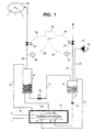
- Fig. 1 shows the principal design of an electrolysis apparatus according to the invention in which hydrogen pressure is used for controlling the pressure, and
- Fig. 2 presents an alternative embodiment in which oxygen pressure is used for controlling the pressure.
-
- Figure 1 presents a
pressure container 10 serving as a pressure shell. Inside thepressure shell 10 there is placed anelectrolytic cell 11 provided with aninlet connector 12 of the electrolytic liquid, withoutlet connectors electricity feeding lines 15. The interior of thepressure shell 10 is moreover filled with a liquid, e.g. silicon oil. Electrolytic liquid, such as water, is conducted by means of gravitation into theelectrolytic cell 11. The embodiment according to Figure 1 presentswater separators - Water is fed into the
electrolytic cell 11 from awater pipe 18 and pump 19 through thepressure shell 10 through awater inlet line 20 conducted into thewater separator 17 of the oxygen gas and further therefrom through awater Inlet line 21 and aback pressure valve 22 positioned therein into aninlet connector 12, and further, into theelectrolytic cell 11. The oxygen gas produced in theelectrolytic cell 11 is conducted through anoxygen outlet connector 13 and anoxygen outlet line 23 to thewater separator 17 of oxygen. The water following the oxygen gas is separated in thewater separator 17 and returns into theelectrolytic cell 11 throughline 21. - The hydrogen gas produced in the
electrolytic cell 11 is conducted through ahydrogen outlet connector 14 and ahydrogen outlet line 25 to awater separator 16 of the hydrogen gas. From the water separator 16 ahydrogen outlet line 28 provided with apressure sensor 26 and avalve 27 leads to a hydrogengas storage container 29. Further, apipe 24 transmitting pressure is led from thewater separator 16 to the interior space of thepressure shell 10 for pressurizing thereof. In addition, awater pipe 31 provided with avalve 30 is conducted from thewater separator 16 of the hydrogen gas to thewater separator 17 of the oxygen gas, whereby the water following the hydrogen gas can be returned to theelectrolytic cell 11 in the above-described manner. - The oxygen gas is conducted from the
water separator 17 to theoxygen outlet line 32 and further for instance into an oxygen container (not shown) when also the oxygen is stored for later use. Theoxygen outlet line 32 is provided with apressure sensor 33 and avalve 34. - The pressure control in the apparatus as shown in Figure 1 can be accomplished preferably so that a
pressure controller 35 has been connected with signal leads 36 and 37 to hydrogen and oxygen pressure sensors 26.33 and according to the signal provided by saidpressure sensors pressure controller 35 opens and shuts throughsignal line valves - Figure 2 presents an apparatus according to figure 1 modified so that oxygen is used for pressurizing. The apparatus according to the invention is otherwise similar as in figure 1, except that the
oxygen outlet pipe 24 is conducted into thepressure shell 10 from the water separator for oxygen. - The above-described embodiments are intended merely to demonstrate, not to limit, the invention.
Claims (7)
- An electrolysis apparatus for producing hydrogen by decomposing electrolytic liquid with the aid of electric current into hydrogen and oxygen in a closed pressurized electrolytic cell (11) placed within a pressure shell (10) filled with a pressurizing liquid, and the pressure shell (10) is communicating with a gas source (16; 17) containing pressurized oxygen or hydrogen produced in the electrolytic cell (11) by a pipe line (24) so that the liquid in the pressure shell (10) is maintained pressurized by means of the pressure of the gas produced in the electrolysis
wherein,
by said pipe line (24), the pressure of the product gas in the gas source is transmitted from said gas source (16; 17) directly to the liquid in the pressure shell (10) to thus directly control the pressure in the pressure shell (10),
the pressure shell (10) is entirely filled with the pressurizing liquid which is kept separate from the electrolytic liquid,
and
a pressure controller (35) is provided and connected to hydrogen and oxygen pressure sensors (26; 33), respectively
said pressure controller controlling the hydrogen and/or oxygen pressure responsive to the measurement results of said pressure sensors. - Electrolysis apparatus according to claim 1, characterized in that said liquid is selected among the following group: silicon oils and fats, fluorized oils, crude oil-based or synthetic oils, water and mixtures thereof.
- Electrolysis apparatus according to claim 1 or 2, characterized in that the said gas is hydrogen.
- Electrolysis apparatus according to claim 1 or 2, characterized in that the said gas is oxygen.
- Electrolysis apparatus according to any one of the preceding claims, characterized in that the hydrogen and oxygen produced in the electrolytic cell (11) are conducted into liquid separators (16 and 17) for separating the electrolysis liquid from the gases and returning them into the electrolytic cell (11).
- Electrolysis apparatus according to claim 5, characterized in that at least one of said liquid separators (16 and 17) is placed outside the pressure shell (10).
- Electrolysis apparatus according to claim 5, characterized in that at least one of said liquid separators (16 and 17) is placed inside the pressure shell (10).
Applications Claiming Priority (3)
| Application Number | Priority Date | Filing Date | Title |
|---|---|---|---|
| FI923904A FI90569C (en) | 1992-08-31 | 1992-08-31 | Electrolyser for hydrogen production |
| FI923904 | 1992-08-31 | ||
| PCT/FI1993/000343 WO1994005830A1 (en) | 1992-08-31 | 1993-08-31 | Electrolysis apparatus for producing hydrogen |
Publications (3)
| Publication Number | Publication Date |
|---|---|
| EP0656959A1 EP0656959A1 (en) | 1995-06-14 |
| EP0656959B1 EP0656959B1 (en) | 1997-04-16 |
| EP0656959B2 true EP0656959B2 (en) | 2004-11-10 |
Family
ID=8535790
Family Applications (1)
| Application Number | Title | Priority Date | Filing Date |
|---|---|---|---|
| EP93919347A Expired - Lifetime EP0656959B2 (en) | 1992-08-31 | 1993-08-31 | Electrolysis apparatus for producing hydrogen |
Country Status (8)
| Country | Link |
|---|---|
| US (1) | US5665211A (en) |
| EP (1) | EP0656959B2 (en) |
| AT (1) | ATE151820T1 (en) |
| AU (1) | AU4961193A (en) |
| CA (1) | CA2143448C (en) |
| DE (1) | DE69309937T3 (en) |
| FI (1) | FI90569C (en) |
| WO (1) | WO1994005830A1 (en) |
Families Citing this family (11)
| Publication number | Priority date | Publication date | Assignee | Title |
|---|---|---|---|---|
| CA2329672C (en) | 2000-12-27 | 2009-12-22 | Donald W. Kirk | Bifurcated electrode of use in electrolytic cells |
| CA2333859A1 (en) | 2001-02-01 | 2002-08-01 | Donald W. Kirk | Electrochemical cell stacks |
| US7559978B2 (en) * | 2005-09-19 | 2009-07-14 | General Electric Company | Gas-liquid separator and method of operation |
| US7727373B2 (en) * | 2006-03-17 | 2010-06-01 | Lawrence Curtin | Hydrogen absorption rod |
| US20070215201A1 (en) * | 2006-03-17 | 2007-09-20 | Lawrence Curtin | Photovoltaic cell with integral light transmitting waveguide in a ceramic sleeve |
| DE102007051230B4 (en) * | 2006-10-23 | 2010-04-08 | SETT Solare Energietechnologien Thüringen GmbH | electrolyzer |
| EP2060661A1 (en) * | 2007-11-16 | 2009-05-20 | AccaGen SA | Electrolyser for producing substances |
| US9011651B2 (en) | 2010-12-09 | 2015-04-21 | Ut-Battelle, Llc | Apparatus and method for the electrolysis of water |
| TWI465301B (en) * | 2012-09-25 | 2014-12-21 | Univ Southern Taiwan Sci & Tec | Preparation device of porous alumina template |
| DE102018213404A1 (en) * | 2018-08-09 | 2020-02-13 | Siemens Aktiengesellschaft | Electrolyser and method for operating an electrolyzer |
| GB2612067A (en) * | 2021-10-20 | 2023-04-26 | Francis Geary Paul | Pressurised electrolyser |
Family Cites Families (7)
| Publication number | Priority date | Publication date | Assignee | Title |
|---|---|---|---|---|
| DE529068C (en) * | 1928-10-02 | 1933-02-01 | Karl Hoffmann | Decomposers, in particular for the electrolysis of water under pressure |
| DE755942C (en) * | 1940-09-06 | 1954-02-01 | Siemens & Halske A G | Electrolytic production of hydrogen and oxygen in the pressure decomposer |
| US3382167A (en) * | 1964-04-01 | 1968-05-07 | Trw Inc | High pressure electrolytic cell module |
| DE2548699C3 (en) * | 1975-10-30 | 1980-06-26 | Linde Ag, 6200 Wiesbaden | Device for the electrolysis of a liquid under pressure |
| FR2448583A1 (en) * | 1979-02-09 | 1980-09-05 | Creusot Loire | IMPROVEMENTS ON A WATER ELECTROLYSIS APPARATUS |
| FR2608715B1 (en) * | 1986-12-19 | 1989-12-01 | Srti Soc Rech Tech Ind | LIQUID LEAKAGE PREVENTION METHOD, AND DEVICE PROVIDED WITH MEANS FOR CARRYING OUT SAID METHOD |
| DE4029634A1 (en) * | 1990-09-19 | 1992-03-26 | Linde Ag | METHOD FOR OPERATING A PRINT ELECTROLYSIS SYSTEM |
-
1992
- 1992-08-31 FI FI923904A patent/FI90569C/en not_active IP Right Cessation
-
1993
- 1993-08-31 EP EP93919347A patent/EP0656959B2/en not_active Expired - Lifetime
- 1993-08-31 AT AT93919347T patent/ATE151820T1/en not_active IP Right Cessation
- 1993-08-31 CA CA002143448A patent/CA2143448C/en not_active Expired - Fee Related
- 1993-08-31 US US08/392,939 patent/US5665211A/en not_active Expired - Fee Related
- 1993-08-31 WO PCT/FI1993/000343 patent/WO1994005830A1/en active IP Right Grant
- 1993-08-31 DE DE69309937T patent/DE69309937T3/en not_active Expired - Fee Related
- 1993-08-31 AU AU49611/93A patent/AU4961193A/en not_active Abandoned
Non-Patent Citations (1)
| Title |
|---|
| Linde "Berichte aus Technik und Wissenschaft" Nr. 66, 1991, ISSN 0024-3728, pages 50 to 54, R. Glatthaar et al, "Konzept einer Hochleistungselektrolyse" † |
Also Published As
| Publication number | Publication date |
|---|---|
| DE69309937T3 (en) | 2005-04-07 |
| FI90569C (en) | 1994-02-25 |
| WO1994005830A1 (en) | 1994-03-17 |
| FI923904A0 (en) | 1992-08-31 |
| US5665211A (en) | 1997-09-09 |
| DE69309937D1 (en) | 1997-05-22 |
| EP0656959A1 (en) | 1995-06-14 |
| AU4961193A (en) | 1994-03-29 |
| CA2143448A1 (en) | 1994-03-17 |
| DE69309937T2 (en) | 1997-10-16 |
| ATE151820T1 (en) | 1997-05-15 |
| CA2143448C (en) | 2000-02-01 |
| EP0656959B1 (en) | 1997-04-16 |
| FI90569B (en) | 1993-11-15 |
Similar Documents
| Publication | Publication Date | Title |
|---|---|---|
| EP0656959B2 (en) | Electrolysis apparatus for producing hydrogen | |
| CN1751139B (en) | Electrolyzer apparatus and method for hydrogen production | |
| US7097748B2 (en) | Electrolyzer pressure equalization system | |
| CN1330792C (en) | High pressure hydrogen producing apparatus and producing method | |
| JP2001130901A (en) | Hydrogen energy supplying unit | |
| EP0659218B1 (en) | Procedure for controlling pressure in electrolysis apparatus and electrolysis apparatus for producing hydrogen and oxygen | |
| US20050109394A1 (en) | Solar electrolysis power co-generation system | |
| CN212315530U (en) | Hydrogen production device by hydrolysis of sodium borohydride of kilowatt-level fuel cell | |
| AU758684B2 (en) | Pressure control system in a water electrolytic cell | |
| CN113594525A (en) | Energy storage, carbon sequestration and new energy recycling | |
| RU2095474C1 (en) | Electrolytic liquid-supply system in pressure electrolysis plant | |
| WO1994005829A1 (en) | Electrolysis apparatus for producing hydrogen | |
| CN2422543Y (en) | Light hydrocarbon liquid fuel vaporising device | |
| CN214890472U (en) | Comprehensive hydrogen station based on hydrogen production by photovoltaic power generation | |
| CN112879152B (en) | Intelligent comprehensive energy management system for oil and gas field | |
| CN109252984A (en) | A kind of energy storage and distributed generation resource electricity generation system based on organic liquid hydrogen storage material | |
| US20230390724A1 (en) | Photocatalyst suspension reactor for solar fuel formation | |
| CA1199668A (en) | Energy conversion system | |
| Gillis et al. | Survey of hydrogen production and utilization methods. Volume 2. Discussion. Final report | |
| FI90884B (en) | Electrolysis apparatus for producing hydrogen | |
| CN2451603Y (en) | Hydrogen fuel generator | |
| Christiansen et al. | Large Scale Hydrogen Production | |
| Ruzz et al. | On-Site Generation of Hydrogen for Generator Cooling | |
| WO2005020352A1 (en) | Electricity production system |
Legal Events
| Date | Code | Title | Description |
|---|---|---|---|
| PUAI | Public reference made under article 153(3) epc to a published international application that has entered the european phase |
Free format text: ORIGINAL CODE: 0009012 |
|
| 17P | Request for examination filed |
Effective date: 19950227 |
|
| AK | Designated contracting states |
Kind code of ref document: A1 Designated state(s): AT CH DE FR GB IT LI SE |
|
| GRAG | Despatch of communication of intention to grant |
Free format text: ORIGINAL CODE: EPIDOS AGRA |
|
| 17Q | First examination report despatched |
Effective date: 19960710 |
|
| GRAH | Despatch of communication of intention to grant a patent |
Free format text: ORIGINAL CODE: EPIDOS IGRA |
|
| GRAH | Despatch of communication of intention to grant a patent |
Free format text: ORIGINAL CODE: EPIDOS IGRA |
|
| GRAA | (expected) grant |
Free format text: ORIGINAL CODE: 0009210 |
|
| AK | Designated contracting states |
Kind code of ref document: B1 Designated state(s): AT CH DE FR GB IT LI SE |
|
| PG25 | Lapsed in a contracting state [announced via postgrant information from national office to epo] |
Ref country code: LI Free format text: LAPSE BECAUSE OF FAILURE TO SUBMIT A TRANSLATION OF THE DESCRIPTION OR TO PAY THE FEE WITHIN THE PRESCRIBED TIME-LIMIT Effective date: 19970416 Ref country code: CH Free format text: LAPSE BECAUSE OF FAILURE TO SUBMIT A TRANSLATION OF THE DESCRIPTION OR TO PAY THE FEE WITHIN THE PRESCRIBED TIME-LIMIT Effective date: 19970416 Ref country code: AT Free format text: LAPSE BECAUSE OF FAILURE TO SUBMIT A TRANSLATION OF THE DESCRIPTION OR TO PAY THE FEE WITHIN THE PRESCRIBED TIME-LIMIT Effective date: 19970416 |
|
| REF | Corresponds to: |
Ref document number: 151820 Country of ref document: AT Date of ref document: 19970515 Kind code of ref document: T |
|
| REG | Reference to a national code |
Ref country code: CH Ref legal event code: EP |
|
| REF | Corresponds to: |
Ref document number: 69309937 Country of ref document: DE Date of ref document: 19970522 |
|
| REG | Reference to a national code |
Ref country code: CH Ref legal event code: NV Representative=s name: R. A. EGLI & CO. PATENTANWAELTE |
|
| ET | Fr: translation filed | ||
| PLBQ | Unpublished change to opponent data |
Free format text: ORIGINAL CODE: EPIDOS OPPO |
|
| PLBI | Opposition filed |
Free format text: ORIGINAL CODE: 0009260 |
|
| PLBF | Reply of patent proprietor to notice(s) of opposition |
Free format text: ORIGINAL CODE: EPIDOS OBSO |
|
| 26 | Opposition filed |
Opponent name: LINDE AKTIENGESELLSCHAFT Effective date: 19980116 |
|
| PLBF | Reply of patent proprietor to notice(s) of opposition |
Free format text: ORIGINAL CODE: EPIDOS OBSO |
|
| PLAW | Interlocutory decision in opposition |
Free format text: ORIGINAL CODE: EPIDOS IDOP |
|
| APAC | Appeal dossier modified |
Free format text: ORIGINAL CODE: EPIDOS NOAPO |
|
| APAE | Appeal reference modified |
Free format text: ORIGINAL CODE: EPIDOS REFNO |
|
| APAC | Appeal dossier modified |
Free format text: ORIGINAL CODE: EPIDOS NOAPO |
|
| RAP2 | Party data changed (patent owner data changed or rights of a patent transferred) |
Owner name: FORTUM OIL AND GAS OY |
|
| REG | Reference to a national code |
Ref country code: CH Ref legal event code: PFA Free format text: NESTE OY TRANSFER- FORTUM OIL AND GAS OY |
|
| REG | Reference to a national code |
Ref country code: GB Ref legal event code: IF02 |
|
| PGFP | Annual fee paid to national office [announced via postgrant information from national office to epo] |
Ref country code: AT Payment date: 20030811 Year of fee payment: 11 |
|
| PGFP | Annual fee paid to national office [announced via postgrant information from national office to epo] |
Ref country code: GB Payment date: 20030827 Year of fee payment: 11 |
|
| PGFP | Annual fee paid to national office [announced via postgrant information from national office to epo] |
Ref country code: CH Payment date: 20031127 Year of fee payment: 11 |
|
| APBU | Appeal procedure closed |
Free format text: ORIGINAL CODE: EPIDOSNNOA9O |
|
| PGFP | Annual fee paid to national office [announced via postgrant information from national office to epo] |
Ref country code: FR Payment date: 20040728 Year of fee payment: 12 |
|
| PGFP | Annual fee paid to national office [announced via postgrant information from national office to epo] |
Ref country code: SE Payment date: 20040817 Year of fee payment: 12 |
|
| PG25 | Lapsed in a contracting state [announced via postgrant information from national office to epo] |
Ref country code: GB Free format text: LAPSE BECAUSE OF NON-PAYMENT OF DUE FEES Effective date: 20040831 |
|
| PUAH | Patent maintained in amended form |
Free format text: ORIGINAL CODE: 0009272 |
|
| STAA | Information on the status of an ep patent application or granted ep patent |
Free format text: STATUS: PATENT MAINTAINED AS AMENDED |
|
| PGFP | Annual fee paid to national office [announced via postgrant information from national office to epo] |
Ref country code: DE Payment date: 20040929 Year of fee payment: 12 |
|
| 27A | Patent maintained in amended form |
Effective date: 20041110 |
|
| AK | Designated contracting states |
Kind code of ref document: B2 Designated state(s): AT CH DE FR GB IT LI SE |
|
| REG | Reference to a national code |
Ref country code: CH Ref legal event code: AEN Free format text: AUFRECHTERHALTUNG DES PATENTES IN GEAENDERTER FORM |
|
| REG | Reference to a national code |
Ref country code: SE Ref legal event code: RPEO |
|
| PLAQ | Examination of admissibility of opposition: information related to despatch of communication + time limit deleted |
Free format text: ORIGINAL CODE: EPIDOSDOPE2 |
|
| PLAR | Examination of admissibility of opposition: information related to receipt of reply deleted |
Free format text: ORIGINAL CODE: EPIDOSDOPE4 |
|
| PLBQ | Unpublished change to opponent data |
Free format text: ORIGINAL CODE: EPIDOS OPPO |
|
| PLAB | Opposition data, opponent's data or that of the opponent's representative modified |
Free format text: ORIGINAL CODE: 0009299OPPO |
|
| GBPC | Gb: european patent ceased through non-payment of renewal fee |
Effective date: 20040831 |
|
| REG | Reference to a national code |
Ref country code: CH Ref legal event code: PL |
|
| R26 | Opposition filed (corrected) |
Opponent name: LINDE AKTIENGESELLSCHAFT Effective date: 19980116 |
|
| PG25 | Lapsed in a contracting state [announced via postgrant information from national office to epo] |
Ref country code: IT Free format text: LAPSE BECAUSE OF NON-PAYMENT OF DUE FEES;WARNING: LAPSES OF ITALIAN PATENTS WITH EFFECTIVE DATE BEFORE 2007 MAY HAVE OCCURRED AT ANY TIME BEFORE 2007. THE CORRECT EFFECTIVE DATE MAY BE DIFFERENT FROM THE ONE RECORDED. Effective date: 20050831 |
|
| PG25 | Lapsed in a contracting state [announced via postgrant information from national office to epo] |
Ref country code: SE Free format text: LAPSE BECAUSE OF NON-PAYMENT OF DUE FEES Effective date: 20050901 |
|
| APAH | Appeal reference modified |
Free format text: ORIGINAL CODE: EPIDOSCREFNO |
|
| ET3 | Fr: translation filed ** decision concerning opposition | ||
| PG25 | Lapsed in a contracting state [announced via postgrant information from national office to epo] |
Ref country code: DE Free format text: LAPSE BECAUSE OF NON-PAYMENT OF DUE FEES Effective date: 20060301 |
|
| PG25 | Lapsed in a contracting state [announced via postgrant information from national office to epo] |
Ref country code: FR Free format text: LAPSE BECAUSE OF NON-PAYMENT OF DUE FEES Effective date: 20060428 |
|
| EUG | Se: european patent has lapsed | ||
| REG | Reference to a national code |
Ref country code: FR Ref legal event code: ST Effective date: 20060428 |