EP0657304B1 - A binding machine using a tape and a binding tape - Google Patents
A binding machine using a tape and a binding tape Download PDFInfo
- Publication number
- EP0657304B1 EP0657304B1 EP94307034A EP94307034A EP0657304B1 EP 0657304 B1 EP0657304 B1 EP 0657304B1 EP 94307034 A EP94307034 A EP 94307034A EP 94307034 A EP94307034 A EP 94307034A EP 0657304 B1 EP0657304 B1 EP 0657304B1
- Authority
- EP
- European Patent Office
- Prior art keywords
- tape
- binding
- aperture
- bonding
- paper
- Prior art date
- Legal status (The legal status is an assumption and is not a legal conclusion. Google has not performed a legal analysis and makes no representation as to the accuracy of the status listed.)
- Expired - Lifetime
Links
- 230000007246 mechanism Effects 0.000 claims description 42
- 238000003780 insertion Methods 0.000 claims description 22
- 230000037431 insertion Effects 0.000 claims description 22
- 230000008275 binding mechanism Effects 0.000 claims description 10
- 239000000853 adhesive Substances 0.000 claims description 5
- 230000001070 adhesive effect Effects 0.000 claims description 5
- 239000004744 fabric Substances 0.000 claims description 5
- 229920000298 Cellophane Polymers 0.000 claims description 2
- 239000011347 resin Substances 0.000 claims 1
- 229920005989 resin Polymers 0.000 claims 1
- 239000000463 material Substances 0.000 description 11
- 239000002184 metal Substances 0.000 description 9
- 238000000034 method Methods 0.000 description 7
- 230000000903 blocking effect Effects 0.000 description 6
- 238000010586 diagram Methods 0.000 description 5
- 210000004905 finger nail Anatomy 0.000 description 4
- 229920003002 synthetic resin Polymers 0.000 description 4
- 239000000057 synthetic resin Substances 0.000 description 4
- 241000221535 Pucciniales Species 0.000 description 2
- 230000008901 benefit Effects 0.000 description 2
- 230000006835 compression Effects 0.000 description 2
- 238000007906 compression Methods 0.000 description 2
- 239000003814 drug Substances 0.000 description 2
- 230000000694 effects Effects 0.000 description 2
- 239000000758 substrate Substances 0.000 description 2
- BZHJMEDXRYGGRV-UHFFFAOYSA-N Vinyl chloride Chemical compound ClC=C BZHJMEDXRYGGRV-UHFFFAOYSA-N 0.000 description 1
- 238000005452 bending Methods 0.000 description 1
- JEIPFZHSYJVQDO-UHFFFAOYSA-N iron(III) oxide Inorganic materials O=[Fe]O[Fe]=O JEIPFZHSYJVQDO-UHFFFAOYSA-N 0.000 description 1
- 238000012986 modification Methods 0.000 description 1
- 230000004048 modification Effects 0.000 description 1
- 239000000123 paper Substances 0.000 description 1
- 230000008569 process Effects 0.000 description 1
- QQONPFPTGQHPMA-UHFFFAOYSA-N propylene Natural products CC=C QQONPFPTGQHPMA-UHFFFAOYSA-N 0.000 description 1
- 125000004805 propylene group Chemical group [H]C([H])([H])C([H])([*:1])C([H])([H])[*:2] 0.000 description 1
- 230000009467 reduction Effects 0.000 description 1
- 238000009751 slip forming Methods 0.000 description 1
Images


Classifications
-
- B—PERFORMING OPERATIONS; TRANSPORTING
- B42—BOOKBINDING; ALBUMS; FILES; SPECIAL PRINTED MATTER
- B42F—SHEETS TEMPORARILY ATTACHED TOGETHER; FILING APPLIANCES; FILE CARDS; INDEXING
- B42F3/00—Sheets temporarily attached together involving perforations; Means therefor; Sheet details therefor
- B42F3/003—Perforated or punched sheets
- B42F3/006—Perforated or punched sheets with edge reinforcing means
-
- B—PERFORMING OPERATIONS; TRANSPORTING
- B42—BOOKBINDING; ALBUMS; FILES; SPECIAL PRINTED MATTER
- B42C—BOOKBINDING
- B42C9/00—Applying glue or adhesive peculiar to bookbinding
- B42C9/0056—Applying glue or adhesive peculiar to bookbinding applying tape or covers precoated with adhesive to a stack of sheets
-
- Y—GENERAL TAGGING OF NEW TECHNOLOGICAL DEVELOPMENTS; GENERAL TAGGING OF CROSS-SECTIONAL TECHNOLOGIES SPANNING OVER SEVERAL SECTIONS OF THE IPC; TECHNICAL SUBJECTS COVERED BY FORMER USPC CROSS-REFERENCE ART COLLECTIONS [XRACs] AND DIGESTS
- Y10—TECHNICAL SUBJECTS COVERED BY FORMER USPC
- Y10S—TECHNICAL SUBJECTS COVERED BY FORMER USPC CROSS-REFERENCE ART COLLECTIONS [XRACs] AND DIGESTS
- Y10S428/00—Stock material or miscellaneous articles
- Y10S428/906—Roll or coil
-
- Y—GENERAL TAGGING OF NEW TECHNOLOGICAL DEVELOPMENTS; GENERAL TAGGING OF CROSS-SECTIONAL TECHNOLOGIES SPANNING OVER SEVERAL SECTIONS OF THE IPC; TECHNICAL SUBJECTS COVERED BY FORMER USPC CROSS-REFERENCE ART COLLECTIONS [XRACs] AND DIGESTS
- Y10—TECHNICAL SUBJECTS COVERED BY FORMER USPC
- Y10T—TECHNICAL SUBJECTS COVERED BY FORMER US CLASSIFICATION
- Y10T428/00—Stock material or miscellaneous articles
- Y10T428/14—Layer or component removable to expose adhesive
- Y10T428/149—Sectional layer removable
-
- Y—GENERAL TAGGING OF NEW TECHNOLOGICAL DEVELOPMENTS; GENERAL TAGGING OF CROSS-SECTIONAL TECHNOLOGIES SPANNING OVER SEVERAL SECTIONS OF THE IPC; TECHNICAL SUBJECTS COVERED BY FORMER USPC CROSS-REFERENCE ART COLLECTIONS [XRACs] AND DIGESTS
- Y10—TECHNICAL SUBJECTS COVERED BY FORMER USPC
- Y10T—TECHNICAL SUBJECTS COVERED BY FORMER US CLASSIFICATION
- Y10T428/00—Stock material or miscellaneous articles
- Y10T428/24—Structurally defined web or sheet [e.g., overall dimension, etc.]
- Y10T428/24273—Structurally defined web or sheet [e.g., overall dimension, etc.] including aperture
- Y10T428/24322—Composite web or sheet
-
- Y—GENERAL TAGGING OF NEW TECHNOLOGICAL DEVELOPMENTS; GENERAL TAGGING OF CROSS-SECTIONAL TECHNOLOGIES SPANNING OVER SEVERAL SECTIONS OF THE IPC; TECHNICAL SUBJECTS COVERED BY FORMER USPC CROSS-REFERENCE ART COLLECTIONS [XRACs] AND DIGESTS
- Y10—TECHNICAL SUBJECTS COVERED BY FORMER USPC
- Y10T—TECHNICAL SUBJECTS COVERED BY FORMER US CLASSIFICATION
- Y10T428/00—Stock material or miscellaneous articles
- Y10T428/24—Structurally defined web or sheet [e.g., overall dimension, etc.]
- Y10T428/24752—Laterally noncoextensive components
Definitions
- the present invention relates to a machine for binding papers, a bag opening and so on and particularly to a binding machine using a tape, which bores an aperture through a bundle of papers and so on and binds the papers and so on with a tape by piercing the tape made of a paper, for example, through the aperture, and a binding tape.
- An existing binding machine is such that a Hotchkiss type stapling machine using a staple cartridge binds the papers by driving a metal staple into a bundle of the papers to an extent that needles of the staple are pierced therethrough and then projected from a rear surface of the papers and by bending f inward the needles of the staple projected from the rear surface of the papers.
- the binding machine using the staple (a stapling machine) according to this method is sometimes encountered by disadvantages such that the staple is stuck into a finger by mistake when the papers are bound and that the needles of the staple catch a cloth and injure a skin if they are not satisfactorily bent but projectingly kept.
- an equipment such as a remover for removing the staple is necessary. Without such remover, it is attempted to remove the staple with a fingernail. However, there is then the risk such that the fingernail is injured and, moreover, clacks if the staple is thick.
- An object of the present invention is to provide a binding machine using a tape, which employs a system of binding papers and so on with a tape made of a material such as paper or the like and eliminates disadvantages of a conventional stapling machine, and a binding tape.
- the binding machine consists of a tape coated with an adhesive, a boring mechanism for boring an aperture by a cutter body through papers and so on to be bound, a binding mechanism using the tape which winds the tape around or halfway around a portion between the bored aperture and an end portion of the papers and so on to be bound and bonds the tape to the papers by pressing the papers by a paper pressing body.
- the binding tape for use in the binding machine is formed by bonding a bonding tape cut at a predetermined interval to an auxiliary tape to be capable of being peeled off from the latter.
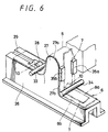
- FIG. 1 is a side view showing the binding machine using the tape according to the embodiment of the present invention in which one side surface portion (a right side surface portion) thereof is removed.
- reference numeral 1 represents the whole of the binding machine using the tape, which consists of a boring mechanism 2 and a binding mechanism 3 including a binding-tape forwarding and guiding mechanism 4 and a mechanism 5 for moving papers and so on to be bound. The papers and so on are bound by the binding machine 1 into which a binding tape 6 is loaded.
- FIG. 2 is a perspective view showing a part of the binding tape according to the embodiment of the present invention.
- reference numeral 6 represents a binding tape which consists of a bonding tape 7 and an auxiliary tape 8 which is mounted with and holds the bonding tape 7 such that the bonding tape 7 can be peeled off therefrom.
- the bonding tape 7 is coated on its rear surface with an adhesive 9 and cut at constant intervals.
- the unit length of the cut bonding tape 7 is determined on the basis of the thickness and binding width of the papers and so on to be bound.
- the unit length of the bonding tape 7 is a length obtained by adding a length twice a width from an end surface p 1 of papers P to be bound to a slit-shaped aperture h bored through the papers P, which will be described later on, and a length twice a thickness of the papers P.
- This unit length is a length calculated on the basis of requirement of a length of the bonding tape 7 sufficient for substantially surrounding a portion between the end surface p 1 of the papers P and the slit-shaped aperture h . Even if the thickness of the papers P to be bound and/or the binding width are a little larger than those obtained from calculation, it leads to only that the bonding tape 7 becomes a little shorter than the length for surrounding the above portion. Therefore, even if the bonding tape is not completely bonded to the above portion, it does not prevent the papers P from being bound satisfactorily.
- the thickness of the papers P and so on to be bound can be given with a room to some extent.
- tape forwarding apertures 10 are bored at constant intervals through the binding tape 6 in which the bonding tapes 7 each having the predetermined length are successively bonded to and held by the auxiliary tape 8 so as to be peeled from the auxiliary tape 8.
- the tape forwarding apertures 10 are positioned between the adjacent bonding tapes 7 and bored through both of the bonding tape 7 and the auxiliary tape 8.
- the tape forwarding apertures 10 are used to forward the bonding tape 7 to be subsequently used into the binding mechanism 3 of the binding machine 1.
- the tape forwarding aperture 10 is engaged with a forwarding projection provided at the moving mechanism 5 which forwards the binding tape 6 in a ganged relation with moving the moving mechanism 5 away from the boring mechanism 2, thereby peeling the bonding tape 7 from the auxiliary tape 8.
- the subsequent bonding tape 7 is prepared for the next binding operation.
- the auxiliary tape 8 is made such that its width is set larger than the width of the bonding tape 7 and both of the side edge portions of the auxiliary tape 8 are used as press edge surface portions 8a, 8b where the bonding tape 7 is not bonded.
- the bonding tape 7 of binding tape 6 described above is previously cut at predetermined intervals, while the bonding tape 7 can be arranged such that it is bonded to and held by the auxiliary tape 8 without being cut but able to be peeled from the auxiliary tape 8 and then only the bonding tape 7 is cut by a tape cutter at optional and random intervals before being inserted into the biding mechanism 3 of the binding machine 1. It can be considered that the bonding tape 7 is not mounted on and held by the auxiliary tape 8.
- the tape forwarding apertures 10 provided through the binding tape 6 are not limited to those shown in FIG. 2.
- the binding tape 6 can have notch portions, not shown, which are provided by cutting the side edge portion of the auxiliary tape 8 and engaged with the above projection or a similar projection to forward the binding tape 6.
- the bonding tape 7 or the auxiliary tape 8 can be gripped at both of its surfaces by roller-shaped members to forward it.
- the binding tape 6 is housed in a housing case C in a state in which the binding tape 6 is rolled around a cylindrical core and the bonding tape 6 can be loaded into and unloaded from the housing case C.
- the tape roll can be freely exchanged.
- a tape feeder (a tape feeding apparatus) can be provided separately.
- reference numeral 1 represents the whole of the binding machine using the tape.
- a housing 11 of the binding machine 1 is formed by combining substantially symmetrical left and right half housings 11a, 11b which can be detachably assembled.
- a main mechanism housing portion 12 for housing a main mechanism consisting of the boring mechanism 2 and the binding mechanism 3 is formed substantially at a center portion of the housing 11 so as to have a shape of an erect cylinder with an opening on its upper surface side.
- a housing portion 14 for housing the binding tape 6 is formed at a rear side of the main mechanism housing portion 12.
- a pressing member 15 is inserted into the main mechanism housing portion 12 of the housing 11 from its upper opening portion 12a so as to be slid in upward and downward directions.
- the pressing member 15 is formed of a holding frame portion 15a inserted into the main mechanism housing portion 12 for holding movable portion of the main mechanism and a pressing handle 15b which is fixed on an upper end of the holding frame portion 15a and projected upward from the main mechanism housing portion 12.
- the holding frame portion 15a of the pressing member 15 holds a blade body 16, which is a main member of the boring mechanism 2, for boring an aperture through the papers to be bound and a pressing body 17 which is a main member of the binding mechanism 3.
- the blade body 16 is formed as will described later on and held by the holding frame portion 15a so that its almost half portion on a blade edge 16a side should be projected downward relative to a lower end of the holding frame portion 15a and so as to be attached and detached.
- the pressing body 17 includes a shaft 17a, a pressing piece 17b horizontally fixed on a lower end of the shaft 17a, and a collar piece 17c fixed on the shaft 17a at a position displaced from its upper end by a predetermined length.
- the pressing body 17 is held by the holding frame portion 15a so as to be projected downward relative to the blade body 16 and to be slid in the upward and downward directions.
- a pressing spring member 18 formed of a compression coil spring, for example, is disposed between the upper end portion, i.e., the collar piece 17c fixed on the shaft 17a of the pressing body 17 and a lower surface of the pressing handle 15b.
- the pressing member 15 includes therein a first restoring spring member 19a and a second restoring spring member 19b which are formed of a compression coil spring, for example.
- the first restoring spring member 19a is fitted at its upper end portion to a lower surface side of the pressing handle 15b to thereby be held so as to be hung, and the second restoring spring member 19b is arranged such that a lower half portion of the first restoring spring member 19a is inserted into the second restoring spring member 19b.
- an insertion opening 12b into which the blade body 16 is inserted, a supporting hole 12c for supporting the shaft 17a of the pressing body 17 inserted thereinto and a dish-shaped bearing surface portion 12d for supporting lower ends of the first and second restoring spring member 19a, 19b are formed at a lower portion of the main mechanism housing portion 12 of the housing 11 into which the pressing member 15 is inserted.
- a contact piece portion 12e is formed at a front edge side of the insertion opening 12b so as to be projected downward.
- a positioning portion 20 for positioning a side of a bind portion of the papers and so on to be bound is provided so as to be located below the above-mentioned supporting aperture 12c.
- the positioning portion 20 is opposed to the above-mentioned pressing piece 17b of the pressing body 17 and consists of a mount surface 20a for mounting thereon the bind portion of the papers and so on and a projecting contact surface 20b along which a rear end edge of the pressing piece 17b is slid and with which the end surface of the bind portion is brought in contact, both of which allows the positioning portion 20 to have a cross section with its shape of a reversed L letter.
- the shaft 17a of the pressing body 17 is inserted into the supporting aperture 12c by inserting the pressing member 15 into the main mechanism housing portion 12 and the first and second restoring spring members 19a, 19b are mounted on and brought at their lower surfaces in contact with the bearing surface portion 12d. Then, the pressing member 15 is slidably pushed upward by a restoring spring force of the first restoring spring member 19a and then positioned on an upper side of the main mechanism housing portion 12 with being considerably projected upward from the upper opening portion 12a. In this state, the blade body 16 is located above the insertion opening 12b so as to be opposed thereto at a predetermined interval.
- the pressing piece 17b of the pressing body 17 is located above the positioning portion 20 so that its lower surface should be opposed to the mount surface 20a at a predetermined interval and its rear end edge should be slidably in contact with the projecting contact surface 20b.
- the pressing piece 17b of the pressing body 17 is brought in contact with the mount surface 20a of the positioning portion 20 and then presses the mount surface 20a because a spring force of the pressing spring member 18 is applied to the shaft 17a.
- the pressing member 15 is further pushed downward, the pressing member 15 is moved downward with contracting the second restoring spring member 19b and the blade body 16 reaches the guide surface 13a of the guide portion 13 through the insertion opening 12b and then is brought below the guide surface 13a after being passed through the insertion opening 12b.
- the pressing piece 17b of the pressing body 17 is strongly pressed on the mount surface 20a.
- the pressing member 15 When the pressing member 15 is released from being pressed from this state, the pressing member 15 is strongly slid and returned upward by the double restoring spring force obtained from the first and second restoring spring members 19a, 19b and the blade body 16 is passed through the guide surface 13a from a lower side thereof to an upper side thereof and then returned into the insertion opening 12b.
- the pressing piece 17b is kept being pressed on the mount surface 20a by the spring force of the pressing spring member 18, and the pressing member 15 is still comparatively slightly slid and returned by the restoring spring force of the first restoring spring force 19a.
- the pressing member 15 is stopped from being pressed on the mount surface 20a and then is moved upward.
- a supporting portion 21 with an opening at its lower end is formed on a front surface side of the main mechanism housing portion 12.
- a rotating pressing body 22 formed of a roller made of a synthetic resin, for example, is inserted into the supporting portion 21 together with a supporting body 22c including a bearing 22a and a spring member 22b therein and held by the supporting portion 21 so as to be projected from a lower opening portion 21a thereof.
- a press contact surface portion 23 which is located at the same level as the mount surface 20a of the positioning portion 20, is provided on the guide surface 13a of the guide portion 13 so as to be opposed to the rotating pressing body 22 springily projected from the lower opening portion 21a of the supporting portion 21.
- An opening 24 is formed between the press contact surface portion 23 and the positioning portion 20, being located below the above blade body 16 which is inserted thereinto.
- a long guide opening 25 extended in forward and backward directions is formed through the guide surface 13a of the guide portion 13 at its center portion to a front side from the press contact surface portion 23.
- the guide opening 25 is formed over both of the half housings 11a, 11b.
- a tape housing portion 14 for housing the binding tape 6 is formed at a rear side of the main mechanism housing portion 12 and houses a tape case C housing the binding tape 6 wound around a roll.
- the tape housing portion 14 is opened and hollow at its rear side, where opening portions 14a 1 , 14b 1 extended to a rear surface opening 14c are respectively formed at both side surface portions 14a, 14b.
- a lower surface portion 14d is formed so as to be inclined to become high in the backward direction, and a front surface 14e is formed perpendicularly to the inclined lower surface 14d. Since the tape housing portion 14 is thus formed, the tape housing case C can be inserted and ejected in a backward and slightly upward diagonal direction with being gripped at its both sides by fingers, so that the tape housing case C can be inserted and ejected smoothly.
- the tape housing portion 14 is communicated to a lower portion of the guide portion 13 through an opening portion 14f formed through a lower portion of the front surface 14e.
- a tape guiding body 26 is fitted to a lower portion of the guide portion 13 of the housing 11 so as to be rotated downward.
- the tape guiding body 26 is formed independently of the housing 11.
- the tape guiding body 26 is formed so as to be long block-shaped in forward and backward directions with being extended from a front end surface of the guide portion 13 to a front surface of the tape housing portion 14 and is engaged with the housing 11 at a lower surface side of the housing 11, i.e., between lower portions of both of the half housings 11a, 11b, thereby becoming integral with the housing 11.
- the tape guiding body 26 is formed as a tape guiding surface 26a at its upper surface side and formed at a portion corresponding to a front edge of the above-mentioned guide portion 13 side opening 24 as a ridge guiding portion 27 which has a top portion 27a formed as a curved surface and is sharply inclined at its rear surface 27b side.
- the tape guiding surface 26a of the tape guiding body 26 is formed at a front side of the ridge guiding portion 27 as a guide surface portion 26a 1 located at a higher position and at a rear side thereof as a guide surface portion 26a 2 located at a lower position.
- a reversing feed blocking click 28 for being engaged with the tape forwarding aperture 10 of the auxiliary tape 8 of the binding tape 6 is projectingly provided adjacent to the ridge guide portion 27 and a guide groove 29 extended to the front end of the tape guiding body 26 from the reversing feed blocking click 28 is formed.
- the tape guiding body 26 is located between both of the half housings 11a, 11b and pivotally supported at its rear end portion by a shaft 31 fixed on a front side lower portion of the front surface opening portion 14f of the tape housing portion 14 so as to be rotated downward.
- the tape guiding body 26 is attached with an engaging stopper 32 so as to be engaged with and held by both the half housings 11a, 11b with being fitted into the housing 11.
- a front side guide pin 33 positioned between the front surface 27a of the ridge guiding portion 27 of the tape guiding body 26 and the reversing feed blocking click 28 and a rear side guide pin 34 positioned so as to correspond to a bent portion between the rear surface 27b of the ridge guiding portion 27 and the rear side guide surface portion 26a 2 are projectingly provided so as to bridge the tape guide surface 26a. As shown in FIG.
- pressing pieces 35a, 35b corresponding to the press edge surface portions 8a, 8b provided at both sides of the auxiliary tape 8 are projectingly provided at an interval substantially equal to a thickness of the auxiliary tape 8 at a portion substantially corresponding to an upper half portion on the side of the rear surface 27b of the ridge guide portion 27.
- the ridge guide portion 27, the front and rear side guide pins 33, 34 and the pressing pieces 35a, 35b form a peeling unit for peeling the bonding tape 7 from the auxiliary tape 8.
- a movable gripping body 40 of the moving mechanism 5 for gripping the papers to be bound and for being moved toward the main mechanism housing portion 12, i.e., the boring mechanism 2 and the binding mechanism 3 is mounted so as to be slid in the forward and backward directions.
- the movable gripping body 40 has two quadrangular gripping boards 41, 42 which are connected to each other at their one sides by a shaft pin 43 in a hinge fashion.
- a guide opening groove 41a having a width substantially equal to the width of the above-mentioned press contact portion 23 on the guide portion 13 is formed through the one (lower side) gripping board 41 from its end edge center portion on the hinge connection side to its substantial center portion of a board surface.
- a pair of pressing springy pieces 42a, 42b located across the guide opening groove 41a of the one gripping board 41 are formed at the other (upper side) gripping board 42 so as to be bent upward in a direction from a free end side portion toward the connection side portion.
- Finger hooking projections 42c are formed on an upper surface of the other gripping board 42.
- the pressing springy pieces 42a, 42b may be formed of a part such as a plate spring or the like independent of the gripping board 42.
- a forwarding click piece 44 for being engaged with the tape forwarding apertures 10 of the auxiliary tape 8 is supported by a supporting frame 45 at a substantial center portion of a lower surface of the one gripping board 41 so as to be rotated in the upward and downward directions and is rotatably biased by a biasing member, not shown, such as a spring or the like so that its tip end engaging portion 44a should constantly be projected downward.
- the forwarding click piece 44 is inserted into the guide opening 25 together with the supporting frame 45 to insert the tip end engaging portion 44a thereof into the guide groove 29 of the tape guiding body 26.
- a long guide piece 46 extended in the forward and backward directions is projectingly provided at one side portion of the lower surface of the one gripping board 41 and is slidably in contact with one side surface of the housing 11, i.e., an outer surface of the right half housing 11b.
- a stopper cam 47 is pivotally fitted to a portion corresponding to the guide piece 46 on the outer side surface of the right side half housing 11b so as to be freely rotatable in the forward and backward directions.
- the stopper cam 47 is constantly rotatably biased by a springy biasing member 48 such as a coil spring or the like in the forward direction.
- the stopper cam 47 is slidably in contact with a lower surface of the guide piece 46 of the gripping board 41 with being rotated backward against a rotation biasing force.
- the stopper cam 47 is brought in contact with the rear end surface of the guide piece 46, which is pressed forward by the biasing force for forward rotation produced by the biasing member 48 of the stopper cam 47, so that the movable gripping body 40 is automatically returned to the front end of the guide portion 13 and then stopped.
- the movable gripping body 40 in the stopped state is moved backward, the movable gripping body 40 is pressed against the biasing force of the stopper cam 47 and then the guide piece 46 rotates the stopper cam 47 backward by pushing the stopper cam 47 backward and is brought slidably in contact with the stopper cam 47 with being located on the cam 47. Then, the movable gripping body 40 can be freely moved backward as described above.
- a cover 49 for covering these members is fitted to the outer side surface of the right half housing 11b with which the guide piece 46 is slidably in contact and to which the stopper cam 47 is pivotally fitted.
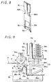
- the above-mentioned blade body 16 is formed as shown in FIG. 8 which shows an example thereof.
- the blade body 16 has a flat board having a wider width as compared with a predetermined width, i.e., the width of the bonding tape 7 of the binding tape 6, and is provided at its tip end with a blade edge 16a curved at its center.
- a tape insertion aperture 16b is bored through the blade body 16 adjacent to the blade edge 16a so as to have a little wider width as compared with the bonding tape 7.
- a tape guide groove 16c having the same width as that of the tape insertion aperture 16b is formed at a portion from the tape insertion aperture 16b to the blade edge 16a. Fitting engaging concave portions 16d 1 , 16d 2 are formed at both side portions of the blade body 16 displaced slightly toward a rear end thereof from a center thereof.
- the tape guide groove 16c is not always necessary.
- the blade body 16 is engaged with and fitted to the above-mentioned holding frame portion 15a of the pressing member 15.
- the tape case C is loaded into the tape housing portion 14 through its rear surface opening 14c. Then, the binding tape 6 housed in the tape case C in the form of the wound roll is drawn through a slit opening c located at a lower end of a case front surface and brought through the front surface opening 14f of the tape housing portion 14 to a portion below the guide portion 13 which is opened by rotating the tape guiding body 26 downward.
- the bonding tape 7 is located on the auxiliary tape 8.
- the binding tape 6 drawn toward the portion below the guide portion 13 is drawn so as to be located under the front and rear guide pins 33, 34 and the front and rear pressing pieces 35a, 35b.
- the tape guiding body 26 is closed, engaged with the housing 11 and stopped by the engaging stopper 32, the binding tape 6 is located along the tape guide surface 26a of the tape guiding body 26 and brought in contact with circumferential surface of the ridge guide portion 27 by being gripped by the front and rear guide pins 33, 34 located at the front and rear sides of the ridge guide portions 27, with being pressed at both side edges of the auxiliary tape 8, i.e., the press edge surface portions 8a, 8b by the pressing pieces 35a, 35b.
- the forwarding click 44 is engaged with one of the tape forwarding apertures 10 of the binding tape 6 in the guide groove 29 of the tape guiding body 26 while the movable gripping body 40 is being slid. Therefore, the binding tape 6 is drawn by an amount of one interval between the adjacent tape forwarding apertures 10 with the movable gripping body 40 being slid forward.
- the binding tape 6 While being drawn and moved, the binding tape 6 is sharply folded at the ridge guide portion 27 of the tape guiding body 26, i.e., folded and substantially turned up along a curved surface top portion 27a of the ridge guide portion 27 with the auxiliary tape 8 being pressed at its both side press edge surface portions 8a, 8b by the pressing pieces 35a, 35b. Therefore, since the bonding tape 7 is bonded to the auxiliary tape 8 with being divided into portions each having a predetermined length, the bonding tape 7 is peeled from the auxiliary tape 8 on its front end side at the curved portion formed by the ridge guide portion 27 and moved with being raised as the auxiliary tape 8 is folded and moved.
- the bonding tape 7 is upward projected from the opening 24 formed between the positioning portion 20 and the press contact surface portion 23 of the guide portion 13 and then located in front of the positioning portion 20. At this time, the bonding tape 7 is held with its front end being temporarily bonded to the contact piece 12e (see FIGS. 1 and 9) and its rear end portion being bonded to the auxiliary tape 8. In this state, the tape forwarding aperture 10 of the auxiliary tape 8 is engaged with the reversing feed blocking click 28 of the tape guiding body 26.
- the preparatory operations for the binding operation are completed.
- the papers P and so on are bound by the binding machine 1
- the papers P and so on are held by inserting its bind side surface p between both of the gripping boards 41, 42 of the movable gripping body 40 returned to the front position of the guide portion 13 and by holding the papers P with the pressing springy boards 42a, 42b of the upper side gripping board 42 (in a state shown by a two-dot chain line shown in FIG. 1).
- the movable gripping body 40 When, in this state, the movable gripping body 40 is slidably moved backward, i.e., toward the main mechanism housing portion 12 and forced so that the guide opening groove 41a of the lower side gripping board 41 should correspond to the press contact surface portion 23, the bind side surface p of the papers P and so on is gripped between the press contact surface portion 23 and the rotating pressing body 22 and then inserted into the lower portion of the main mechanism housing portion 12. At this time, the bonding tape 7 held in the above raised state is bonded to the end surface p 1 on the bind side surface p and then brought onto the positioning portion 20.
- the bonding tape 7 is folded and positioned at a portion slightly extended downward from the opening 24 with its front half portion being located between the bind side surface p and a sidewise U letter-shaped surface formed of a portion from the mount surface 20a and the projected contact surface 20b of the positioning portion 20 to the lower surface of the pressing piece 17b of the pressing body 17 and with its rear half portion being bonded to the auxiliary tape 8.
- the auxiliary tape 8 is pulled by the bonding tape 7 but engaged with and held by the reversing feed blocking click 28 because the tape forwarding aperture 10 is engaged with the reversing feed blocking click 28, so that the bonding tape 7 is smoothly peeled.
- the pressing body 17 When the pressing member 15 is pushed down by pressing the pressing handle 15b against a restoring spring force of the first restoring spring member 19a in this state, the pressing body 17 is pressed and lowered through the pressing spring member 18 with being in contact with a front end portion side of the front half portion of the bonding tape 7.
- the pressing body 17 is pressed onto the bind side surface p of the papers P and then presses the bind side surface p together with the mount surface 20a of the positioning portion 20. Therefore, the bonding tape 7 is tightly bonded at its front half portion side to the portion from an upper surface side of the bind side surface p through the end surface p 1 thereof to a lower surface side thereof (see FIG. 10).
- the pressing member 15 When the pressing member 15 is further pressed, the pressing member 15 is moved downward with contracting the second restoring spring member 19b as described above and the blade body 16 is lowered through the insertion opening 12b.
- the blade edge 16a of the blade body 16 reaches the bind side surface p of the papers P and is stuck by the pressing pressure of the pressing member 15 into the bind side surface p .
- the blade body 16 bores a slit-shaped aperture h having the same size as a lateral cross section of the blade body 16 through the bind side surface p and inserted through the opening 24 to a portion below the guide portion 13.
- the rear half portion of the bonding tape 7 At a position where the blade body 16 is inserted, the rear half portion of the bonding tape 7 is positioned with its rear end being bonded to the auxiliary tape 8 as described above.
- the rear half portion of the bonding tape 7 is slidably brought in contact with the blade body 16 and then peeled from the auxiliary tape 8, and at the same time the rear half portion thereof is inserted into the tape insertion aperture 16b of the blade body 16 by a restitution force of the rear half portion thereof caused by its being peeled off (see FIG. 11).
- the pressing body 17 is kept pressing the bind side surface p of the papers P by the contracted pressing spring member 18.
- the pressing member 15 When the pressing member 15 is stopped from being pressed in this state, the pressing member 15 is strongly slidably returned upward by the double restoring spring force obtained from the first and second restoring spring members 19a, 19b and at the same time the blade body 16 is also promptly lifted up together with the pressing member 15, so that the blade body 16 can be reliably drawn through the opening 24 from the aperture h bored through the bind side surface p of the papers P.
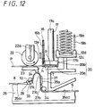
- the rear end portion of the bonding tape 7 inserted into the tape insertion aperture 16b of the blade body 16 is brought upward through the aperture h of the bind side surface p from its lower surface side to its upper surface side with following the blade body 16 which is being lifted (see FIG. 12).
- the rear end portion of the bonding tape 7 is kept inserted into the tape guide groove 16c between the blade edge 16a of the blade body 16 and the tape insertion aperture 16b thereof and hence accommodated therein so as not to be projected in a direction of the thickness of the blade body 16.
- the pressing body 17 is kept pressing the bind side surface p because being pressed by the spring force of the pressing spring member 18. Therefore, the rear end portion of the bonding tape 7 can be smoothly drawn from the aperture h having the same size as the lateral cross section of the blade body 16.
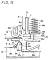
- the bind side surface p of the papers P is passed between the rotating pressing body 22 and the press contact surface portion 23 with following the sliding movable gripping body 40.
- the rear end portion of the bonding tape 7 drawn on the upper surface side of the bind side surface p is folded by the rotating pressing body 22 toward the upper surface side of the bind side surface p and the bonding tape 7 is bonded to the bind side surface p so as to have a shape of a substantially reversed C letter.
- the rear end portion of the bonding tape 7 is gripped and pressed together with the bind side surface p by the rotating pressing body 22, which is pressed by the spring member 22c, and the press contact portion 23, so that the whole surface of the bonding tape 7 is tightly bonded to the bind side surface p (see FIG. 13).
- the movable gripping body 40 is slid and drawn to the front end portion of the guide portion 13 to detach the papers P bound by the bonding tape 7.
- the papers P are bound by the bonding tape 7 in a state shown by an arrow a in FIG. 3.
- the forwarding click 44 provided in the movable gripping body 40 is engaged with the tape forwarding aperture 10 of the binding tape 6 to forward the auxiliary tape 8 from which the bonding tape 7 is peeled.
- the movable gripping body 40 is moved to the front end portion of the guide portion 13, as described above, the movable gripping body 40 is automatically moved because the guide piece 46 is pressed by the stopper cam 47 in the forward direction. The movement of the movable gripping body 40 permits the binding tape 6 to be forwarded by a length of the next one unit.
- the binding tape 6 is forwarded, i.e., the auxiliary tape 8 is moved, in order to prepare the next binding operation, the next bonding tape 7 is held with being peeled from the auxiliary tape 8 and raised similarly to the above-mentioned preparatory operations.
- the papers P and so on are bound by the bonding tape 7 as described above, so that the auxiliary tape 8 is successively forwarded and ejected from the front end surface side of the tape guiding body 26.
- the ejected auxiliary tape 8 can be cut and removed by engaging its tape forwarding aperture 10 with the cutting projection 30 projectingly provided on the front end surface of the tape guiding body 26 to pull out the auxiliary tape 8.
- the bonding tape 7 has a length obtained by adding the length twice the length from the end surface p 1 of the papers P to the aperture h to the length twice the thickness of the papers P to be bound, i.e., the length of the bonding tape 7 is set to a length sufficient to substantially surround the portion between the end surface p 1 of the papers P and the aperture h , while difference in thickness of the papers P to be bound can be solved by setting the length of the bonding tape 7 a little longer.
- the bonding tape 7 is inserted and bonded in the above embodiment in the following processes.
- One end of the bonding tape 7 is bonded to the upper surface of the end portion of the papers P to be bound and the bonding tape 7 is perpendicularly folded and then bonded to the end surface p 1 of the papers P.
- the bonding tape 7 is further perpendicularly folded and bonded to the lower surface of the papers P.
- the bonding tape 7 is inserted through the tape threading apertur e h bored by the blade body 16 and bonded to an end surface, where the aperture is provided, of the papers P.
- the bonding tape 7 is further perpendicularly folded to bond the other end thereof to the upper surface around the aperture h of the papers P.
- the bonding tape 7 is folded in a tube fashion and bonded to the papers P so as to surround a part of the papers P, and the bound bonding tape 7 has a cross section having a shape of the C letter counterclockwise turned at an angle of 90°.
- the bonding tape 7 bonded to the papers P does not always have a bind shape of the C letter clockwise turned at an angle of 90° and may have shapes of U letter counterclockwise or clockwise turned at an angle of 90° as shown by arrows b and c in FIG. 3, respectively.
- the tape threading apertures h can be bored by the blade body 16 at two optional positions which are not limited to the end portion of the papers P as shown by an arrow d in FIG. 3, thereby bonding the bonding tape 7 in a substantial shape of the C letter turned counterclockwise at an angle of 90°.
- Two methods of threading the bored aperture h with the bonding tape 7 can be considered: the former, as shown in FIG. 1, is that, as described in the above embodiment, the bonding tape 7 is inserted into the tape insertion aperture 16b provided through the center of the blade body 16 after the blade body 16 bores the aperture h through the papers P and when the blade body 16 is pulled out, the blade body 16 is drawn together with the bonding tape 7 to thread the tape insertion aperture 16b with the bonding tape 7; and the latter is that the bonding tape 7 is previously inserted into the tape insertion aperture 16b provided through the center of the blade body 16 before the boring operation and the blade body 16 bores the aperture h through the papers P with the bonding tape 7 being inserted thereinto to thread the aperture h with the bonding tape 7.
- the method of threading the tape insertion aperture 16b with the bonding tape 7 is not limited to these methods.
- This embodiment adopts the blade body 16 having the blade edge 16a which is reversed mountain-shaped and curved upward at its center.
- the shape of the blade body 16 is not limited to the above shape.
- an ordinary blade is formed in the form of a single blade edge which is mountain-shaped and sharply curved downward at its center.
- the number of the blade body is not limited to one, but the blade having a plurality of blade edges can be adopted. It can be freely selected whether the blade edge 16a is single-blade-edged or double-blade-edged and which direction the blade edge is directed in.
- this embodiment can adopt a method in which a small aperture with a predetermined width used for passing the bonding tape 7 therethrough is bored through the end portion of the papers P by using a box-shaped boring blade for boring a rectangular aperture or a circular shaped boring blade. In this case, it may be facilitated to pass the bonding tape 7 through the bored aperture h .
- the arranged blade portion lifts the bonding tape to the upper surface of the papers P to pass the bonding tape 7 through the bored aperture in this embodiment, if a wider aperture is formed, then the bonding tape 7 can be passed through the bored aperture h with ease, so that it is unnecessary to pass the bonding tape 7 through the bored aperture h as described in the embodiment.
- the blade body 16 can bore the aperture h in a vertical direction upward from a portion below the papers P.
- the bonding tape 7 is inserted into the tape insertion aperture 16b provided through the center of the blade body 16 after the aperture h is bored through the papers P, the bonding tape 7 can be previously inserted into the tape insertion aperture 16b before the blade body 16 bores the aperture h through the papers P.
- first restoring spring member 19a may be employed as the restoring springy body for slidably returning the pressing member 15, and there can be employed a spring member in which the first and second restoring spring members 19a, 19b are integrally formed, i.e., integrally continuously formed so that a spring force at its lower portion should be strong.
- the binding machine using the tape according to the present invention enjoys the following effects because it has an arrangement described in detail above and does not use a metal staple.
- the binding machine using the tape and the binding tape according to the present invention enjoys many advantages and effects as described above.
- the binding machine and a refill for the binding tape serving as the bind material can be provided with inexpensive prices as compared with that of the conventional stapling machine. Therefore, the binding machine using the tape and the binding tape according to the present invention is economical and excellent in practical use.
Description
Claims (14)
- A binding machine (1) for binding together a plurality of sheets of paper (P) comprising:said boring mechanism (2) comprises a blade body (16) for boring an aperture through a plurality of sheets of paper, said blade body (16) having a tape insertion aperture (16b) bored through the centre portion thereof for receiving said binding tape (6) and drawing said binding tape through the said paper aperture as the blade body (16) moves through the said paper aperture.a binding tape (6);a boring mechanism (2); anda binding mechanism (3); characterised in that
- The binding machine (1) as claimed in Claim 1, wherein the boring mechanism (2) further comprises a pressing member (15) for supporting said blade body (16) and a spring member (19a) for returning said pressing member upward.
- The binding machine (1) as claimed in Claim 1 or Claim 2, wherein said blade body (16) of said boring mechanism (2) has a blade edge (16a) which, in use, is sharply curved downward at its centre or a concave blade edge (16a) which, in use, is curved upward at its centre.
- The binding machine (1) as claimed in Claim 1 or Claim 2, wherein said blade body (16) of said boring mechanism (2) has a circular type or box type boring blade.
- The binding machine (1) as claimed in any one of Claims 1 to 4, wherein said binding mechanism (3) further comprises a peeling unit (27,33,34,35a,35b) for peeling a bonding tape (7) with a predetermined length of said binding tape (6) from an auxiliary tape (8), a first pressing body (17) for pressing and bonding a head end of said bonding tape (7) to a front surface of said sheets of paper (P), a rotating second pressing body (22) for pressing and bonding a tail end of said bonding tape (7) to a rear surface of said sheets of paper (P), a movable gripping body (40) for gripping the papers to be bound and for slidably inserting the said sheets of paper into said boring mechanism (2), and a projection portion (44) provided on a rear portion of said movable gripping body (40) for engaging with a forwarding aperture (10) of the binding tape (6) in a ganged relation with movement of the movable gripping body and for forwarding the binding tape.
- The binding machine (1) as claimed in Claim 5, wherein said movable gripping body (40) of the binding mechanism (3) has two rectangular boards (41,42) which are engaged at respective sides thereof in a hinge fashion so as to freely grip papers, and apertures at respective centres of the rectangular boards (41,42) to pass said bonding tape (7) therethrough.
- The binding machine (1) as claimed in any one of the preceding claims, further comprising threading means for threading the said paper aperture with said bonding tape (7) by inserting said bonding tape into the tape insertion aperture (16b) of the blade body (16) before the said paper aperture is bored through the said sheets of paper, whereby the bonding tape (7) is passed through the said paper aperture at the same time as when the said paper aperture is bored.
- The binding machine (1) as claimed in any one of Claims 1 to 6, further comprising threading means for threading the said paper aperture with said bonding tape (7) by inserting said bonding tape into the tape insertion aperture (16b) of the blade body (16) after the said paper aperture is bored through the said sheets of paper, whereby the inserted bonding tape (7) is passed through the said paper aperture when said blade body returns through the said paper aperture.
- The binding machine (1) as claimed in any one of the preceding claims, wherein the binding tape comprises:a bonding tape (7) coated on its rear surface with an adhesive (9) which is cut at predetermined intervals; andan auxiliary tape (8) on which said bonding tape (7) is bonded in a manner to be peeled therefrom.
- The binding machine (1) according to Claim 9, wherein tape forwarding apertures (10) are bored through at least said auxiliary tape (8) in a longitudinal direction at constant intervals.
- The binding machine (1) according to Claim 9 or Claim 10, wherein said auxiliary tape (18) is wider in width than said bonding tape (7) such that portions where no tape is to be bonded are formed at both side portions thereof.
- The binding machine (1) according to any one of Claims 9 to 11, wherein said bonding tape (7) is made of a paper tape coated on its rear surface with an adhesive (9).
- The binding machine (1) according to any one of Claims 9 to 11, wherein said bonding tape (7) is made of a transparent cellophane tape, a cloth tape or a resin tape coated on its rear surface with an adhesive (9).
- The binding machine (1) according to any one of Claims 9 to 14, wherein a tape forwarding notch portion is provided at a side end of said auxiliary tape (8).
Applications Claiming Priority (4)
| Application Number | Priority Date | Filing Date | Title |
|---|---|---|---|
| JP26780993A JPH07101178A (en) | 1993-10-01 | 1993-10-01 | Binder with tape |
| JP267809/93 | 1993-10-01 | ||
| JP06182446A JP3122807B2 (en) | 1994-08-03 | 1994-08-03 | Tape binding device |
| JP182446/94 | 1994-08-03 |
Publications (2)
| Publication Number | Publication Date |
|---|---|
| EP0657304A1 EP0657304A1 (en) | 1995-06-14 |
| EP0657304B1 true EP0657304B1 (en) | 1998-09-02 |
Family
ID=26501246
Family Applications (1)
| Application Number | Title | Priority Date | Filing Date |
|---|---|---|---|
| EP94307034A Expired - Lifetime EP0657304B1 (en) | 1993-10-01 | 1994-09-27 | A binding machine using a tape and a binding tape |
Country Status (4)
| Country | Link |
|---|---|
| US (2) | US5697747A (en) |
| EP (1) | EP0657304B1 (en) |
| DE (1) | DE69412976T2 (en) |
| ES (1) | ES2121155T3 (en) |
Families Citing this family (11)
| Publication number | Priority date | Publication date | Assignee | Title |
|---|---|---|---|---|
| JPH09327982A (en) * | 1996-06-10 | 1997-12-22 | Lintec Corp | Binding tape paper and binding tape |
| US6030166A (en) * | 1999-05-24 | 2000-02-29 | Tekpak Corporation | Mechanism for loading a lashing tape of a binding machine |
| US20040007317A1 (en) * | 2002-07-12 | 2004-01-15 | Chia-Hsiung Wu | Applying a hot melt band to paper sheet covering |
| US7320694B2 (en) * | 2004-03-11 | 2008-01-22 | Coopersurgical, Inc. | Obturator tip |
| US7217075B2 (en) * | 2004-07-16 | 2007-05-15 | Krdc Co., Ltd. | Tape feeder and method of controlling the same |
| JP4830478B2 (en) * | 2005-12-19 | 2011-12-07 | マックス株式会社 | Binding mechanism and paper staple of tape-type binding device |
| JP6040746B2 (en) | 2012-12-12 | 2016-12-07 | マックス株式会社 | Stapler |
| JP2015067407A (en) * | 2013-09-30 | 2015-04-13 | 株式会社リコー | Sheet binding device and image forming device |
| JP6645339B2 (en) * | 2016-04-22 | 2020-02-14 | マックス株式会社 | Stapler |
| CN108859252A (en) * | 2018-06-14 | 2018-11-23 | 安徽徽之润纸业有限公司 | A kind of carton binding device that can be used for producing on line |
| CN112026396B (en) * | 2020-08-06 | 2022-01-25 | 曹雪松 | Full-automatic financial binding machine |
Citations (2)
| Publication number | Priority date | Publication date | Assignee | Title |
|---|---|---|---|---|
| DE3509844A1 (en) * | 1983-09-09 | 1986-11-06 | Julius Bauer GmbH, 7129 Talheim | Device for processing a double-sided adhesive tape |
| US4906314A (en) * | 1988-12-30 | 1990-03-06 | Micron Technology, Inc. | Process for simultaneously applying precut swatches of precured polyimide film to each semiconductor die on a wafer |
Family Cites Families (13)
| Publication number | Priority date | Publication date | Assignee | Title |
|---|---|---|---|---|
| FR395161A (en) * | 1908-10-12 | 1909-02-13 | Otto Thaele | Binding and method and devices for making it |
| US1980267A (en) * | 1933-01-26 | 1934-11-13 | Nevett Ltd | Bookbinding |
| FR96182E (en) * | 1968-06-24 | 1972-05-19 | Koenig C | Apparatus for stitching registers, books or similar articles using adhesive tapes. |
| US3501365A (en) * | 1969-07-11 | 1970-03-17 | Litton Business Systems Inc | Pressure sensitive label strip construction |
| US4335172A (en) * | 1977-03-28 | 1982-06-15 | Kabushiki Kaisha Sato | Pressure sensitive label strip |
| DE3005625C2 (en) * | 1980-02-15 | 1986-08-14 | Esselte Pendaflex Corp. (n.d. Ges.d. Staates Calif.), Garden City, N.Y. | Label tape |
| AU543774B2 (en) * | 1982-09-30 | 1985-05-02 | Esselte Pendaflex Corp. | Label tape |
| US4552497A (en) * | 1984-05-21 | 1985-11-12 | The Mead Corporation | Apparatus and method for preparing multipage, taped, side-stitched documents |
| GB8510589D0 (en) * | 1985-04-25 | 1985-05-30 | Lawhill Design & Eng Services | Binding machine |
| US5153043A (en) * | 1989-10-04 | 1992-10-06 | Seal King Industrial Co., Ltd. | Laterally tearing tape strip |
| US5262216A (en) * | 1992-08-04 | 1993-11-16 | Avery Dennison Corporation | Pressure sensitive label assembly |
| US5366333A (en) * | 1992-09-11 | 1994-11-22 | Velo-Bind, Inc. | Motorized binding machine |
| US5413384A (en) * | 1993-03-08 | 1995-05-09 | Monarch Marking Systems, Inc. | Composite label for use in couponing |
-
1994
- 1994-09-23 US US08/311,188 patent/US5697747A/en not_active Expired - Fee Related
- 1994-09-27 ES ES94307034T patent/ES2121155T3/en not_active Expired - Lifetime
- 1994-09-27 DE DE69412976T patent/DE69412976T2/en not_active Expired - Fee Related
- 1994-09-27 EP EP94307034A patent/EP0657304B1/en not_active Expired - Lifetime
-
1995
- 1995-09-08 US US08/526,061 patent/US5679428A/en not_active Expired - Fee Related
Patent Citations (2)
| Publication number | Priority date | Publication date | Assignee | Title |
|---|---|---|---|---|
| DE3509844A1 (en) * | 1983-09-09 | 1986-11-06 | Julius Bauer GmbH, 7129 Talheim | Device for processing a double-sided adhesive tape |
| US4906314A (en) * | 1988-12-30 | 1990-03-06 | Micron Technology, Inc. | Process for simultaneously applying precut swatches of precured polyimide film to each semiconductor die on a wafer |
Also Published As
| Publication number | Publication date |
|---|---|
| US5697747A (en) | 1997-12-16 |
| DE69412976D1 (en) | 1998-10-08 |
| ES2121155T3 (en) | 1998-11-16 |
| DE69412976T2 (en) | 1999-01-14 |
| US5679428A (en) | 1997-10-21 |
| EP0657304A1 (en) | 1995-06-14 |
Similar Documents
| Publication | Publication Date | Title |
|---|---|---|
| EP0695648B1 (en) | A binding machine using a tape and a binding tape | |
| EP0657304B1 (en) | A binding machine using a tape and a binding tape | |
| JPH07101178A (en) | Binder with tape | |
| US7334620B2 (en) | Adhesive tape cutter | |
| US20060113043A1 (en) | Adhesive binding tape cutter | |
| US4274906A (en) | Apparatus for automatically applying reinforcing tabs to loose-leaf sheets | |
| JPH1024669A (en) | Binding device | |
| AU581250B2 (en) | Decollator for tearing off strip side/edges | |
| JPH10871A (en) | Binding tool using tape | |
| EP0096764A2 (en) | Portable label applying machine | |
| JP2018150160A (en) | Tape cutter | |
| US8684059B2 (en) | Method and apparatus for tabbing manually-manipulated folded material | |
| US4904333A (en) | Decorative binding apparatus | |
| JPH084307Y2 (en) | Cartridge of tape for backing | |
| JP2003011932A (en) | Tape binder | |
| JPH0732090Y2 (en) | Guide for booklet on back attachment device | |
| JPS625340Y2 (en) | ||
| JPH043935Y2 (en) | ||
| JPH0113043Y2 (en) | ||
| JP2003025753A (en) | Binder using tape | |
| JPH0732089Y2 (en) | Tape feeding device for spine attachment device | |
| JP2000302316A (en) | Pressure sensitive adhesive double coated tape sticker, and sticking method for the tape | |
| JP3124891U (en) | Tape binder | |
| GB2055346A (en) | Tab inserters | |
| TW201632369A (en) | Binding device |
Legal Events
| Date | Code | Title | Description |
|---|---|---|---|
| PUAI | Public reference made under article 153(3) epc to a published international application that has entered the european phase |
Free format text: ORIGINAL CODE: 0009012 |
|
| AK | Designated contracting states |
Kind code of ref document: A1 Designated state(s): DE ES FR GB IT |
|
| 17P | Request for examination filed |
Effective date: 19951120 |
|
| 17Q | First examination report despatched |
Effective date: 19970115 |
|
| GRAG | Despatch of communication of intention to grant |
Free format text: ORIGINAL CODE: EPIDOS AGRA |
|
| GRAG | Despatch of communication of intention to grant |
Free format text: ORIGINAL CODE: EPIDOS AGRA |
|
| GRAH | Despatch of communication of intention to grant a patent |
Free format text: ORIGINAL CODE: EPIDOS IGRA |
|
| GRAH | Despatch of communication of intention to grant a patent |
Free format text: ORIGINAL CODE: EPIDOS IGRA |
|
| GRAA | (expected) grant |
Free format text: ORIGINAL CODE: 0009210 |
|
| AK | Designated contracting states |
Kind code of ref document: B1 Designated state(s): DE ES FR GB IT |
|
| REF | Corresponds to: |
Ref document number: 69412976 Country of ref document: DE Date of ref document: 19981008 |
|
| REG | Reference to a national code |
Ref country code: ES Ref legal event code: FG2A Ref document number: 2121155 Country of ref document: ES Kind code of ref document: T3 |
|
| PG25 | Lapsed in a contracting state [announced via postgrant information from national office to epo] |
Ref country code: GB Free format text: LAPSE BECAUSE OF NON-PAYMENT OF DUE FEES Effective date: 19981202 |
|
| ET | Fr: translation filed | ||
| PLBE | No opposition filed within time limit |
Free format text: ORIGINAL CODE: 0009261 |
|
| STAA | Information on the status of an ep patent application or granted ep patent |
Free format text: STATUS: NO OPPOSITION FILED WITHIN TIME LIMIT |
|
| GBPC | Gb: european patent ceased through non-payment of renewal fee |
Effective date: 19981202 |
|
| 26N | No opposition filed | ||
| PGFP | Annual fee paid to national office [announced via postgrant information from national office to epo] |
Ref country code: DE Payment date: 20001009 Year of fee payment: 7 |
|
| PGFP | Annual fee paid to national office [announced via postgrant information from national office to epo] |
Ref country code: FR Payment date: 20001010 Year of fee payment: 7 |
|
| PGFP | Annual fee paid to national office [announced via postgrant information from national office to epo] |
Ref country code: ES Payment date: 20001013 Year of fee payment: 7 |
|
| PG25 | Lapsed in a contracting state [announced via postgrant information from national office to epo] |
Ref country code: ES Free format text: LAPSE BECAUSE OF NON-PAYMENT OF DUE FEES Effective date: 20010928 |
|
| PG25 | Lapsed in a contracting state [announced via postgrant information from national office to epo] |
Ref country code: DE Free format text: LAPSE BECAUSE OF NON-PAYMENT OF DUE FEES Effective date: 20020501 |
|
| PG25 | Lapsed in a contracting state [announced via postgrant information from national office to epo] |
Ref country code: FR Free format text: LAPSE BECAUSE OF NON-PAYMENT OF DUE FEES Effective date: 20020531 |
|
| REG | Reference to a national code |
Ref country code: FR Ref legal event code: ST |
|
| REG | Reference to a national code |
Ref country code: ES Ref legal event code: FD2A Effective date: 20021011 |
|
| PG25 | Lapsed in a contracting state [announced via postgrant information from national office to epo] |
Ref country code: IT Free format text: LAPSE BECAUSE OF NON-PAYMENT OF DUE FEES Effective date: 20050927 |