EP0659327B1 - Best server selection in layered cellular radio systems - Google Patents
Best server selection in layered cellular radio systems Download PDFInfo
- Publication number
- EP0659327B1 EP0659327B1 EP94921137A EP94921137A EP0659327B1 EP 0659327 B1 EP0659327 B1 EP 0659327B1 EP 94921137 A EP94921137 A EP 94921137A EP 94921137 A EP94921137 A EP 94921137A EP 0659327 B1 EP0659327 B1 EP 0659327B1
- Authority
- EP
- European Patent Office
- Prior art keywords
- cell
- base station
- signal strength
- preference
- radio
- Prior art date
- Legal status (The legal status is an assumption and is not a legal conclusion. Google has not performed a legal analysis and makes no representation as to the accuracy of the status listed.)
- Expired - Lifetime
Links
- 230000001413 cellular effect Effects 0.000 title claims abstract description 42
- 238000000034 method Methods 0.000 claims description 44
- 238000004891 communication Methods 0.000 claims description 31
- 230000010267 cellular communication Effects 0.000 claims description 7
- 238000012545 processing Methods 0.000 claims description 7
- 230000004044 response Effects 0.000 claims description 5
- 210000004027 cell Anatomy 0.000 description 264
- 238000011156 evaluation Methods 0.000 description 10
- 210000003850 cellular structure Anatomy 0.000 description 8
- 230000008569 process Effects 0.000 description 7
- 238000010586 diagram Methods 0.000 description 6
- 239000010410 layer Substances 0.000 description 6
- 238000005259 measurement Methods 0.000 description 5
- 239000002356 single layer Substances 0.000 description 4
- 230000007423 decrease Effects 0.000 description 3
- 238000013459 approach Methods 0.000 description 2
- 238000013461 design Methods 0.000 description 2
- 238000005516 engineering process Methods 0.000 description 2
- 238000005562 fading Methods 0.000 description 2
- 230000000977 initiatory effect Effects 0.000 description 2
- 238000012986 modification Methods 0.000 description 2
- 230000004048 modification Effects 0.000 description 2
- 230000011664 signaling Effects 0.000 description 2
- 238000012546 transfer Methods 0.000 description 2
- 230000033228 biological regulation Effects 0.000 description 1
- 230000005540 biological transmission Effects 0.000 description 1
- 230000001351 cycling effect Effects 0.000 description 1
- 230000003247 decreasing effect Effects 0.000 description 1
- 230000004069 differentiation Effects 0.000 description 1
- 239000011229 interlayer Substances 0.000 description 1
- 238000012423 maintenance Methods 0.000 description 1
- 238000001228 spectrum Methods 0.000 description 1
Images


Classifications
-
- H—ELECTRICITY
- H04—ELECTRIC COMMUNICATION TECHNIQUE
- H04W—WIRELESS COMMUNICATION NETWORKS
- H04W36/00—Hand-off or reselection arrangements
- H04W36/04—Reselecting a cell layer in multi-layered cells
-
- H—ELECTRICITY
- H04—ELECTRIC COMMUNICATION TECHNIQUE
- H04W—WIRELESS COMMUNICATION NETWORKS
- H04W36/00—Hand-off or reselection arrangements
- H04W36/24—Reselection being triggered by specific parameters
- H04W36/30—Reselection being triggered by specific parameters by measured or perceived connection quality data
- H04W36/304—Reselection being triggered by specific parameters by measured or perceived connection quality data due to measured or perceived resources with higher communication quality
-
- H—ELECTRICITY
- H04—ELECTRIC COMMUNICATION TECHNIQUE
- H04W—WIRELESS COMMUNICATION NETWORKS
- H04W16/00—Network planning, e.g. coverage or traffic planning tools; Network deployment, e.g. resource partitioning or cells structures
- H04W16/24—Cell structures
- H04W16/32—Hierarchical cell structures
-
- H—ELECTRICITY
- H04—ELECTRIC COMMUNICATION TECHNIQUE
- H04W—WIRELESS COMMUNICATION NETWORKS
- H04W36/00—Hand-off or reselection arrangements
- H04W36/24—Reselection being triggered by specific parameters
- H04W36/30—Reselection being triggered by specific parameters by measured or perceived connection quality data
Definitions
- the invention relates to handoff of mobile stations within cellular radio systems and, more particularly, to handoff within layered cell structures of such systems.
- a geographic area is divided into a plurality of individual regions referred to as cells, each of which is provided with radio service on a plurality of separate RF channels the frequencies of which are reused among different cells sufficiently separated from one another that there is a sufficiently low level of interference between them.
- a mobile station receiving radio service from a particular base station serving a particular cell moves from that cell into another adjacent cell, communication with the mobile station is "handed off" from the first base station to the second base station serving the adjacent cell.
- Such handoff is accomplished by a mobile switching center (MSC) to which all of the base stations are connected and which controls the allocation of communication channels to the individual mobiles moving throughout the region served by the cells.
- MSC mobile switching center
- TDMA time division multiple access
- Such microcells may have a coverage or service area on the order of a few hundred yards in contrast to a few kilometers of coverage by the base station of the overlying umbrella cell.
- a plurality of such microcells may be located adjacent to one another and form a contiguous coverage area of substantial width all of which is within the overall coverage area of the umbrella cell.
- a layered cell structure as described above in conjunction with umbrella cells and microcells, is used there is provided an enhanced level of radio capacity which can be configured for individual circumstances and which provides an assurance that users can receive service despite an extremely high demand within a very small geographic area.
- additional layers of radio coverage may be added, for example, by a plurality of either contiguous or separated "pico cells" positioned within the coverage or service area of the individual microcells, each of which are in turn within the overall umbrella cell.
- the base stations providing the radio coverage within the pico cells would be of even still lower power than the base stations serving the microcells and have a coverage or service area of, for example, a few hundred feet to provide coverage within a single building or a single floor within a large convention center.
- the issue of server selection and handoff of each mobile radio transceiver moving within a geographic area involves many more options. That is, it is possible for the mobile station to receive radio service at any given moment from either a pico cell base station, a microcell base station, or an umbrella cell base station.
- a pico cell base station a pico cell base station
- a microcell base station a microcell base station
- an umbrella cell base station a pico cell base station
- the ability to configure the handoff arrangement for maximum efficiency with respect to the utilization of channel availability and consistent with high quality radio service to each mobile subscriber is highly desirable.
- the principle criterion used is that the quality of the signal received from the mobile station by the respective base stations capable of providing radio service. That is, the quality of the signal received from the mobile station by the base station currently serving the mobile is compared with the quality of signal received by a base station serving an adjacent cell and when the quality of signal in the latter exceeds the former, the mobile is handed off to the base station serving the adjacent cell.
- a signal quality increment known as an offset or hysteresis, is also applied to the signal quality difference value so that unless the signal quality in the adjacent base station is at least "x" amount greater than the presently serving base station, handoff does not occur. This prevents oscillating handoffs due to signal quality perturbations in which the mobile is repeatedly handed back and forth between two adjacent base stations.
- Reference WO 92/02105 teaches a handover initiation system that utilizes mobile station distance from the base station and signal strength information to determine mobile user path and location within a microcell. This information may then be used to determine a handover to another microcell.
- Reference EP 0526436 teaches a method for interlayer handover. A handover from a microcell is made first to the overlying macrocell. Once accomplished, if the mobile is slow moving, a subsequent handover may be made to a different microcell.
- mobile subscribers are served by the base station of the cell level which is the preferred service provider for that mobile as long as the signal quality is above a selected minimum value. Should the signal quality deteriorate below that selected minimum value, best server selection possibilities are evaluated on the same level and such possibilities are first exhausted before handoff is made to a cell on a lower preference level.
- handoff is performed of a mobile station operating within a cellular radio system in a region in which radio channels are provided by multiple levels of cells having different service areas. Categories of preference are assigned within each cell with respect to each other associated cell within the system as to which said cell's service area is either adjacent, contiguous, or overlapping.
- the signal strength of the radio signals providing communication between the mobile station and the base station serving each of the associated cells within the system is measured and compared to a preselected threshold value. Whether or not to handoff the mobile to a base station serving an associated cell is determined based upon whether the signal strength of the radio signal therefrom is greater than the threshold value and the preference assigned to the associated cell.
- best server selection is performed for a mobile station served on a first radio channel by a first base station serving a first cell and operating within a cellular radio system in a region in which radio channels are provided by multiple levels of cells having different service areas. Categories of preference are assigned within each cell with respect to each other associated cell within the system as to which said cell's service area is either coextensive adjacent, contiguous, or overlapping. Each associated cell is assigned a category of preferred, equal preference or non-preferred based upon the size of its service area relative to that of the cell within which the assignment is made.
- Information on a second radio channel broadcast by a second base station serving a second associated cell is received and stored.
- the signal strength of the radio signals broadcast on the first and second radio channels, respectively, are measured.
- the preference category of the cell from which said second radio channel signal is received is determined.
- the second base station broadcasting the second radio channel is selected as the best server in response to any one of the following conditions, (a) the second cell having a preference category of preferred and the signal strength of the radio signal of said second radio channel being greater than a preselected value, (b) the second cell having a preference category of equal preference and the signal strength of the radio signal of the second radio channel being greater than the signal strength of the radio signal of the first radio channel, or (c) the second cell having a preference category of non-preferred and the signal strength of the first radio channel being less than a preselected value and the signal strength of the radio signal of the second radio channel being greater than that of the first radio channel.
- server selection is performed for a mobile station operating within a cellular radio system in a region in which radio channels are provided by multiple levels of cells.
- Each of the cells is provided with radio service by a base station the broadcast power of which and the resultant service area of which varies from larger to smaller.
- Each cell is provided with a list of neighboring cells the service areas of which are proximately associated with the service area of the cell.
- a minimum acceptable radio channel signal strength value is assigned for each cell.
- the strength of the radio signals providing communication between the mobile station and the base station is measured for the cell currently serving the mobile station as well for each of the neighboring cells thereof.
- a server is selected for the mobile station from among the currently serving cell and its neighboring cells by choosing the cell having both the smallest service area and a radio signal strength which is at least equal to the minimum acceptable value.
- FIG. 1 there is illustrated a conventional single layer cellular radio communication system of the type to which the present invention has a relationship.
- an arbitrary geographic area may be divided into a plurality of contiguous radio coverage areas, or cells C1-C10. While the system of FIG. 1 is illustratively shown to include only 10 cells, it should be clearly understood that in practice, the number of cells will be much larger.
- each of the base stations B1-B10 includes a transmitter, receiver, and base station controller as is well known in the art.
- the base stations B1-B10 are illustratively located at the center of each of the cells C1-C10, respectively, and are equipped with omni-directional antennas.
- the base stations B1-B10 may be located near the periphery, or otherwise away from the centers of the cells C1-C10 and may illuminate the cells C1-C10 with radio signals either omni-directionally or directionally. Therefore, the representation of the cellular radio system of FIG. 1 is for purposes of illustration of a single level cellular radio system only and is not intended as a limitation on the possible implementations of the cellular radio system within which the system of the present invention may find utility.
- a plurality of mobile stations M1-M10 may be found within the cells C1-C10. Again, only 10 mobile stations are shown in FIG. 1 but it should be understood that the actual number of mobile stations will be much larger in practice and will invariably greatly exceed the number of base stations. Moreover, while none of the mobile stations M1-M10 will be found in some the cells C1-C10, the presence or absence of the mobile stations M1-M10 in any particular one of the cells C1-C10 should be understood to depend, in practice on the individual desires of the mobile stations M1-M10 who may roam from one location in the cell to another or from one cell to an adjacent cell or neighboring cell, and even from one cellular radio system served by an MSC to another system.
- Each of the mobile stations M1-M10 is capable of initiating or receiving a telephone call to one or more of the base stations B1-B10 and a mobile switching center (MSC).
- a mobile switching center (MSC) is connected by communication links, e.g., cables, to each of the illustrative base stations B1-B10 and to the fixed public switch telephone network (PSTN), not shown, or a similar fixed network which may include an integrated system digital network (ISDN) facility.
- PSTN public switch telephone network
- ISDN integrated system digital network
- the relevant connections between the mobile switching center (MSC) and the base stations B1-B10, or between the mobile switching center (MSC) and the PSTN or ISDN, are not completely shown in FIG. 1 but are well known to those of ordinary skill in the art.
- Each of the cells C1-C10 is allocated a plurality of voice or speech channels and at least one access or control channel, such as a forward control channel (FOCC).
- the control channel is used to control or supervise the operation of mobile stations by means of information transmitted to and received from those units. Such information may include incoming call signals, outgoing call signals, page signals, page response signals, location registration signals, voice channel assignments, and maintenance instructions as the mobile station travels out of the radio coverage of one cell and into the radio coverage of another cell.
- the control or voice channels may operate either in an analog or digital mode or a combination thereof.
- FIG. 1 illustrates a relatively conventional single level cellular structure in which mobile stations are handed off from one cell to another by it being served with radio channels in communication with first one base station and then an adjacent base station based upon the signal level of the mobile station received from each of the respective base stations.
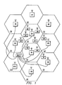
- FIG. 2 there is shown an illustrative multi-level layered cellular architecture in which a plurality of umbrella macrocells A-G, analogous to the cells C1-C10 of FIG. 1, overlie and include a plurality of microcells a-e located within the same service area of one or more of the umbrella cells.
- each of the umbrella cells A-G would be served respectively by a base station, similar to the base stations B1-B10 of FIG. 1, and it would include a service area within a cell on the order of, for example, several kilometers in diameter.
- each of the microcells a-e would also be served by a base station (not shown) located within the cell and providing a respective service area on the order of a few hundred meters for each.
- a base station located within the cell and providing a respective service area on the order of a few hundred meters for each.
- the service areas of the umbrella cells A-G are adjacent, contiguous or overlapping to one another, so also are the service areas of the respective microcells a-d contiguous to one another, with the service area of microcell e being isolated from the other microcells but coextensive within the service area of the umbrella cell A.
- Each of the base stations providing radio coverage for both the umbrella cells A-G and the microcells a-e could be operated under the control of a single MSC (not shown).
- a mobile station 21 moving along the path identified by arrow 22 would move from the region served by umbrella cell A through the regions served by microcell d and microcell c and into the coverage area of umbrella cell B.
- Providing radio service to the mobile station 21 as it moves along the path 22 could involve a number of different handoffs from different serving base stations at different points along the way depending upon the handoff criteria or handoff algorithm used to implement such handoffs.
- the mobile station 21 could only be provided with service by the base station serving the umbrella cell A, while at point 23 along the path 22 it could be served either by the base station of umbrella cell A or the base station of microcell d.
- the mobile station 21 when it reached point 24 on the path 22, it could be served either by the base station of umbrella cell A or the base station of microcell c. Further, at point 25, service could be provided by the base station of microcell c or the base station of umbrella cell B. Finally, at point 26 on path 22, the mobile station 21 could only be provided with service by the base station serving umbrella cell B.
- the decision criteria with respect to which cell the mobile station 21 should be handed off to and the criteria which should be used to determine both the timing and the result of that handoff are important considerations in configuring the efficiency and capacity of radio service to be provided to the mobile stations within the multi-layered cellular structure of FIG. 2.
- a mobile station in implementing the handoff process within a single layer cellular structure, is only located in one cell at a time and leaves the old cell behind when it enters and begins receiving service by virtue of handoff to the new cell. In such case, the signal strength received from the mobile station decreases for the old cell and increases for the new cell when the handoff border is crossed by the mobile station.
- a microcell when a microcell is placed within an umbrella cell and is totally surrounded by the umbrella cell, there is an entirely different situation with respect to the variation in signal strength as the mobile moves through the microcell located within the umbrella cell.
- both the serving cell signal strength and the candidate cell signal strength are increasing or decreasing, depending upon the direction of movement of the mobile station. This variation in signal strength becomes more and more of a problem the closer to the antenna site serving the umbrella cell site the microcell is located.
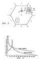
- an umbrella cell has 50 watts erp (47dbm) and an enclosed microcell 0.1 watt erp (20dbm).
- the microcell is placed 200 meters from the base station site of the umbrella cell.
- 0.1 watts is an appropriate power level for a 200 meter diameter microcell.
- signal offset value is set to 10db, i.e., 10db is subtracted from the measured umbrella cell signal strength before comparison to two cells in accordance with standard single level cell architecture handoff algorithms.
- the signal strength of the signal received by a mobile station from the umbrella cell moving from the base station location of the umbrella cell toward and through the base station site of the microcell begins quite high and decreases exponentially as a function of the distance between the mobile station and the umbrella cell base station.
- the signal strength received by the mobile station from the microcell increases exponentially until it passes through the base station serving the microcell at 200 meters distance from the base station of the umbrella cell and then decreases exponentially thereafter as a similar function of the distance from the microcell base station.
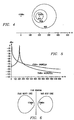
- the nominal handoff border offset value of 10d being applied when the signals are compared, meaning that the nominal handoff border is the line where the umbrella cell is 10d stronger than the microcell.
- the maximum and minimum cell size is found where the umbrella cell is 18db and 2db stronger, which are shown by the inner and outer line of FIG. 4, respectively.
- the lowest signal strength in the microcell is found to be around -97dbm. Such a case may work and might be acceptable in some cases, however, the uncertainty of the handoff borders is relatively high.
- FIG. 5 is a graph showing the signal strength from the two cells at the different distances from the respective base station of the umbrella cell and the microcell as the mobile travels from the base station of the umbrella cell through the base station of the microcell and then away from both. While the overall structure of the respective signal level curves is similar to that shown in FIG. 3, the overlapping relationship is somewhat different.
- the nominal handoff border i.e, the line where the umbrella signal strength is 17db higher than that of the microcell signal strength
- the straight line in FIG. 6 As discussed above, inaccuracies in the mobile and hysteresis values are added giving borders at 9db and 25db offsets, respectively.
- the umbrella cell and the microcell are equivalent.
- the umbrella cell In the worse case, the umbrella cell is the small one and the best case the microcell is the small one. This example illustrates what can easily happen if the offset is set too high in an attempt to get a reasonable coverage.
- the present algorithm used in the case of single level cellular structures functions adequately to use relative signal strength between current cells and neighboring cells in order to locate handoff borders when the cells are of equal preference and located side by side.
- Another criterion is needed for handoff between umbrella cells and microcells.
- the system of the present invention provides handoff criterions based on absolute signal strength. That is, when the serving cell is the umbrella cell and the signal strength for a microcell neighbor, measured by the mobile station in digital cellular systems and by the signal strength receiver in analog cellular systems, is above a "sufficient" signal level, so as to ensure a good speech quality in the microcell, a handoff can be made to the microcell. This criterion ensures that a handoff to the microcell is performed whenever it can give service of sufficient quality.
- a general approach inherent in the system of the present invention is to handle each of the cells as belonging to distinctly different layers, i.e., macrocells, microcells, pico cells, etc., without defining different layer types.
- three categories of neighboring cells (1) neighbors beside, (2) neighbors above, and (3) neighbors below, such a classification is useful.
- a "neighbor beside" will be an existing neighbor on the same level as the currently serving cell. Neighbors above for a microcell would be an umbrella cell and neighbors below for an umbrella cell would be microcells.
- handoff should be accomplished to a neighbor below whenever the signal strength in that neighbor is above a new "sufficient" threshold value to be defined as a cell parameter.
- handoff to a neighbor above for example, the umbrella cell, should only be done when the signal strength is below the same threshold provided that it is a better candidate.
- a hysteresis value will be applied to the threshold in order to avoid oscillating handoffs.
- new cell parameters and neighbor type information are sent by the exchange to the base station and, in the base station, these parameters must be added to the digital channel software as new criteria for sending handoff requests.
- analog channels such corresponding software criteria must be located in the exchange itself.
- a basic concept inherent in the present invention is that it is desirable to serve a mobile station by means of a cell level within a multi-cell structure which is at the lowest possible level provided the signal quality is sufficient to provide good service.
- a cell level within a multi-cell structure which is at the lowest possible level provided the signal quality is sufficient to provide good service.
- FIG. 2 including an array of umbrella cells and microcells positioned therein, and in which it possible to provide coverage from either the umbrella cell or the microcell, it is normally optimal to allow the microcell to handle the subscriber traffic whenever it is appropriate from the standpoint of quality transmission.
- the microcell i.e., the lowest level of cells in the multi-cell array, is preferred.
- one layer is generally preferred over the other primarily for capacity reasons.
- the system and method of the present invention is implemented based upon the processing of a list of neighbor cells and upon the differentiation between preferred cells, non-preferred cells and cells with equal preference in order to ascertain the most appropriate serving cell both at time of call setup as well as during the call itself.
- the microcells a, c, d, e are preferred to the umbrella cell A
- microcells a, b, c are preferred to the umbrella cell B
- umbrella cells A-G have equal preference to each other
- microcells a-e have equal preference to each other.
- one goal is to ensure that the mobile subscriber radio transceiver is tuned to the most appropriate cell both during the idle mode as well as during the call process.
- the algorithm used in the present invention is employed to select a cell which is the same in both idle and during the process of a call in order to make sure that the cell as selected at call setup is also accepted immediately after the call setup.
- Parameter Description 1 A selected signal strength threshold which defines a sufficiently "acceptable" signal strength for the cell 2
- a list of neighboring cells 4 For each neighbor, an assigned type, i.e., preferred, non-preferred, equal preference 5
- an assigned hysteresis value In case there is no qualified preferred neighbor and the signal strengths in the currently serving cell is below the threshold, then the "best" cell should be selected and handed off to. The hysteresis value of parameter 5 is used in this particular situation.
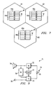
- each cell comprises a base station 44-46 each of which comprises a control channel transceiver 44a-46a as well as a plurality of voice channel transceivers 44b-46b.
- the control channel of the base station is used for communication with mobile stations during idle period when no call has been established.
- the signalling placed on the control channel includes the information to be broadcast to the mobile stations relating to neighboring cells.
- the voice channels are used after call setup to a mobile station and carry not only voice data but also certain signalling, for example, measurement channel numbers for the neighboring cells to the cell serving the mobile station, as well as a handoff order to the mobile and measured signal strength from the neighboring cells to the cell serving the mobile station in the case of mobile assisted handoff (MAHO) under the IS-54 digital standard.
- signalling for example, measurement channel numbers for the neighboring cells to the cell serving the mobile station, as well as a handoff order to the mobile and measured signal strength from the neighboring cells to the cell serving the mobile station in the case of mobile assisted handoff (MAHO) under the IS-54 digital standard.
- MAHO mobile assisted handoff
- FIG. 8 there is shown an overall block diagram of the equipment within the cellular network within which the present invention is incorporated, including the public switched telecommunication network (PSTN) 51, a mobile switching center (MSC) 52, and a pair of illustrative base stations 53-54.
- PSTN public switched telecommunication network
- MSC mobile switching center
- the interface 57 of the MSC 52 is coupled by means of data lines 51 and 60 to each of the respective base stations 53 and 54.
- Each base station includes a multiplexer/demultiplexer 60 connected to a plurality of transceivers 63-65 connected to an antenna 66.
- Each transceiver includes a control unit 67 and a transmit unit 68 along with a receive unit 69.
- Calls to or from subscribers in the PSTN 51 are connected to the switch 55 within the MSC 52 where they are routed to the correct cell and voice channel controlled by the central processor 56.
- the central processor 56 also administers and processes data regarding the location of the mobile, the neighboring cells to the cell within which the mobile is currently located, and control both call setup and handoff.
- the links between the MSC 52 and the base stations 53 and 54 (links 61 and 62) carries voice data, as well as control information to and from the control unit 67 within each of the different transceivers 63-65 of the base stations 53 and 54.
- the base station equipment 53 and 54 consists of the multiplexer 60 which administrates distribution of voice data and control information to and from the different transceivers 63-65.
- the transceivers include both control channel transceivers and voice channel transceivers.
- a mobile subscriber unit 71 including a receiver 72, a transmitter 73 connected to an antenna 74 through a duplexer 75.
- a control unit 76 is coupled to a synthesizer 77 which is also coupled to the transmitter 73 and receiver 72.
- a microphone 78 is connected to the transmitter 73 while a speaker 79 is connected to the receiver 72.
- the synthesizer 77 is used to tune the receiver 72 to the control channel frequencies before call setup and to different voice channel frequencies and measurement channel frequencies during the call and under control of the control unit 76.
- the control unit 76 measures by means of the receiver and the SYNT the signal strength of the signal being received by the receiver 72, receives neighbor list information from the base station via the receiver 72 and processes all of the information according to the algorithm and technique of the present invention.
- a mobile unit in idle searches the assigned frequency spectrum being broadcast for an appropriate control channel for communication with the cellular network. All control channels are continuously transmitting and are cyclically broadcasting neighbor cell information which is valid for the cell within which the mobile is currently located.
- the neighbor cell information consists of the following data:
- the mobile station measures the signal strength periodically for the current channel and at the frequencies defined for the current cell's neighbors. The mobile then tunes to a preferred neighbor as soon as the measured signal strength for this neighbor is above the threshold set for this neighbor cell. If more than one preferred neighbor is qualified, the mobile tunes to the neighbor with the best margin with respect to the threshold value. If, however, there is no qualified preferred neighbor cell and a neighbor cell with equal preference has a signal strength which is higher than the signal strength to the current channel with a margin which is defined by the hysteresis value for that particular neighbor, the mobile then retunes to this neighbor cell.
- the mobile tunes to this neighbor cell's control channel frequency.
- the mobile When a call setup from the mobile is attempted, the mobile is already on an appropriate control channel according to the procedure set forth above and the call can be set up in the corresponding cell according to the well-established procedures.
- Another way to provide the mobile with the frequencies, the neighbor types, two signal strength levels, i.e., the threshold and the hysteresis, and another hysteresis would be to broadcast the threshold and the hysteresis separately and let the mobile calculate the two levels.
- Another way to describe the algorithm is: (1) tune to a preferred neighbor when the measured signal strength is "good enough”; (2) do not tune to a non-preferred neighbor when the measured signal strength for the currently serving cell is "good enough”; and (3) tune to the best neighbor when the signal strength for the serving cell is not "good enough”.
- a mobile subscriber terminal moving from umbrella cell A to umbrella cell B will first be tuned to cell A's control channel frequency where it will receive broadcast information regarding control channel frequencies for neighboring cells B-G with equal preference as well as their hysteresis values together with the frequencies for the preferred neighbor microcells a, b, d, e and their corresponding threshold values.
- the mobile When the signal strength from microcell d is above the threshold value set for that cell, the mobile will retune to microcell d's control channel and receive information about microcell d's neighbor cells which are now microcell a and microcell c with equal preference, and umbrella cell A as a non-preferred neighbor cell.
- the neighbors with equal preference will be microcell a, microcell b, and microcell d and the non-preferred neighbors will be umbrella cell A and umbrella cell B.
- the mobile station When the mobile station has reached a location within umbrella cell B, it will have umbrella cells A, C and G as neighbors with equal preference and microcells a, b, c as preferred neighbors.
- the system of the present invention provides an easier and more natural way to control selection of a cell at call setup and at handoff.
- the system also provides a system for optimal cell selection within such a multi-layered cell structure.
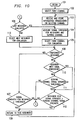
- FIG. 10 illustrates a process performed within the mobile during idle period as follows: the routine begins at 101 and moves to 102 at which it selects a first channel. Thereafter, the mobile moves to 103 where it receives and stores information broadcast on the selected channel. Next, at 104 the mobile station measures the signal strength for-the neighboring cells and for the serving channel. Thereafter, at 105 the mobile selects a first channel for evaluation and moves to 106 where it is determined whether or not that channel comes from a preferred neighbor cell.
- the system moves to 107 at which it is determined whether or not the signal strength for the neighbor cell is greater than a preselected threshold value plus the hysteresis, if any. If not, the system moves to 108 where it is determined whether or not the last neighbor has been evaluated. If, however, at 107, the signal strength for the neighbor cell is greater than the threshold value plus the hysteresis, if any, the system moves to 109 and the mobile station retunes to this neighbor cell value and returns to 103 to receive and store information broadcast on this newly selected channel.
- the system moves to 110 where it is determined whether or not the neighbor cell is one with equal preference. If not, i.e., the cell is a non-preferred neighbor cell, the system moves to 111 at which it determines whether or not the serving channel signal strength is less than a preselected threshold value plus the hysteresis, if any. If not, it moves to 108 to determine if the last neighbor has been evaluated.
- the system moves to 112 where it is determined whether or not the neighbor cell's signal strength is greater than the serving channel's signal strength and, if not, moves to 108 and determines whether or not the last neighbor has been evaluated. If, at 112 the neighbor cell's signal strength is determined to be greater than the serving channel's signal strength, then the mobile station retunes to this neighbor cell at 109 and returns to 103 to receive and store information broadcast on this channel. Similarly, if it is determined at 110 that this neighbor cell is a cell of equal preference, the system moves directly to 112 to evaluate the signal strength of that cell.
- the system determines if the last neighbor has been evaluated, the system returns to 104 and measures the signal strength for the neighboring cells in the serving channel as set forth above. If, however, the last neighbor cell is determined to have not been evaluated at 108, the system moves to 113 and selects the next neighbor for evaluation returning to 106 to determine the preference of that particular neighbor.
- the mobile station during idle period is continually cycling through the reception of channel information and determining whether or not it is appropriate to be handed off to a cell and applying a preference to those potential cells to which it may be handed off in accordance with the most efficient utilization of channel availability.
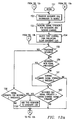
- the routine begins at 121 where the mobile selects a first channel at 122 and moves to 123 where it receives and stores information broadcast on that selected channel. Thereafter, the system moves to 124 and measures signal strength for the neighboring cells and serving channels thereof. Next, at 125 the system selects the first channel for evaluation and clears a candidate channel list. Thereafter, at 126 the system determines whether or not the selected channel is that of a preferred neighbor and, if so, moves to 127 where the signal strength for the neighboring cell is evaluated to determine whether or not it is above a preselected threshold value plus the hysteresis, if any.
- the system moves to 128 and it is determined whether or not the last neighbor has been evaluated. If, however, at 127, it has been determined that the signal strength for the neighboring cell was greater than the threshold value, the system moves to add this neighbor's cell to the candidate list at 129 and thereafter to decision 128 to evaluate whether or not the last neighbor has been evaluated. If, however, at 126 it is determined that the neighbor was not preferred, the system moves to 131 to determine whether or not the neighboring cell is one with equal preference or not.
- the system moves to 132 and determines whether or not the serving channel strength is less than a preselected threshold value minus the hysteresis, if any, and, if not, to decision 128 to determine if the last neighbor has been evaluated. If, however, at 132 the serving channel signal strength is determined to be greater than a threshold value plus the hysteresis, if any, the system moves to 133 at which it is determined whether or not the neighbor cell signal strength is greater than the serving channel signal strength and, if not, to a decision as to whether or not the last neighbor has been evaluated at 128.
- the system moves to 129 and adds this neighbor to the candidate list. If, at 131 it is determined that the cell is a neighbor with equal preference, the system moves directly to decision 133 to determine if the neighboring cell signal strength is greater than the serving channel signal strength.
- the system moves to 134 to select the next neighbor for evaluation and thereafter to decision 126 to begin that evaluation. If the last neighbor has been evaluated at 128, the system moves to 135 and determines whether or not any candidates have been found. If not, the system returns to 124 and, if so, moves to 136 to sort the candidate list. Thereafter, the system moves to 137 and retunes to the first candidate on the list followed by moving to 123 where it receives and stores the information broadcast on that selected channel.
- the system engages in an orderly evaluation of possible channels and selects a channel based upon criteria determined to provide maximum efficiency and channel utilization in a multi-layered cell structure.
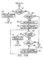
- FIGS. 12a-12b there is shown a routine which may be executable in the system by either the mobile station and/or base station during an established call within an exemplary digital cellular system.
- the system begins at 151 by moving to 152 at which it transfers neighbor cell information from the base station to the mobile. Thereafter, at 153 the system measures the signal strength for the neighboring cells and serving channels. Next, at 154 the system selects a first channel for evaluation and clears a candidate list. Thereafter, at 155 the system determines if the selected channel is from a preferred neighbor cell and, if so, moves to 156 where it determines whether or not the signal strength for that neighbor cell is greater than the preselected threshold value plus the hysteresis, if any.
- the system moves to 157 and determines if the last neighbor has been evaluated. If, at 156 the signal strength of the neighboring cell is greater than the threshold value plus the hysteresis, if any, the system moves to 158 and adds this neighbor to the candidate list. If, at 155 the cell is determined not to be a preferred neighbor, the system moves to 159 to determine if the neighboring cell is one with equal preference and, if not, to 161 to determine if the serving channel signal strength is less than the preselected value minus the hysteresis, if any. If not, the system moves to 157 to determine if the last neighbor has been evaluated.
- the system moves to 162 where it is determined whether or not the neighboring cell signal strength is greater than a serving channel signal strength plus the hysteresis, if any, and, if so, to 158 to add this neighbor to a candidate list and, if not, to 157 to determine if the last neighbor has been evaluated. If, at 159 it is determined that the neighboring cell is one with equal preference, the system moves directly to 162 to determine if that neighboring cell signal strength is greater than the serving channel signal strength plus the hysteresis, if any.
- the system moves to 163 to select the next neighbor for evaluation and thereafter evaluates it beginning at step 155. If, at 157 it is determined that the last neighbor has been evaluated, the system moves to 164 to determine if candidates are found and, if not, back to 153 to measure the signal strength for neighbors and the serving channels. If candidates are found at 164, the system moves to 165 to sort the candidate list and, thereafter to 166 to select a first candidate cell for a handoff attempt.
- the system determines whether or not an idle channel exists in the candidate cell and, if not, moves to 168 to determine if this is the last candidate and, if so, to 169 wherein it selects the next candidate cell for a handoff attempt. If the cell was the last candidate at 168, the system moves back to 153 to measure the signal strength for neighbors and serving channels. If the idle channel in the candidate cell exists, the system moves to 171 and hands off to this candidate cell and, thereafter, returns to 152 to transfer neighboring cell information to the mobile.
- the system of the present invention utilizes algorithms which maximize the channel utilization from various cells within a multi-layered cell structure in a highly efficient manner.
- the present invention allows a multi-layered cellular communication system to monitor channel signal strength in a plurality of cells on multiple levels and perform an evaluation in accordance with an algorithm which maximizes the channel availability within the multi-layered cellular structure.
Abstract
Description
- The invention relates to handoff of mobile stations within cellular radio systems and, more particularly, to handoff within layered cell structures of such systems.
- In cellular radio communication systems a geographic area is divided into a plurality of individual regions referred to as cells, each of which is provided with radio service on a plurality of separate RF channels the frequencies of which are reused among different cells sufficiently separated from one another that there is a sufficiently low level of interference between them. When a mobile station receiving radio service from a particular base station serving a particular cell moves from that cell into another adjacent cell, communication with the mobile station is "handed off" from the first base station to the second base station serving the adjacent cell. Such handoff is accomplished by a mobile switching center (MSC) to which all of the base stations are connected and which controls the allocation of communication channels to the individual mobiles moving throughout the region served by the cells.
- As the demand for cellular radio service increases over time, the capacity of existing systems has been severely stressed to serve all the subscribers who would like to have access to the system, particularly in major metropolitan areas. To address this demand, cellular radio technology is currently moving from analog based systems, in which each subscriber communication channel is allocated to a single radio channel, to digital based systems in which a plurality of subscriber channels can be assigned to each radio channel through time division multiple access (TDMA) radio technology. In TDMA radio, each radio channel is divided into a plurality of time slots and a digitized portion of each subscriber's conversation is broadcast in a different time slot. However, even with such improvements in channel capacity, there exist certain areas within major metropolitan areas in which the demands on the system are so great that it cannot be successfully satisfied by existing cellular radio architectures. For example, in the area in and around a convention center located in a major metropolitan area, the channel usage by portable cellular radio transceivers may be so great that the demands for service cannot be satisfied by the entire channel capacity of the base station serving the cell within which the convention center is located. In such situations, it has been proposed to provide additional "layers" of cellular radio coverage provided by additional lower powered base stations located within an existing, so-called "umbrella" cell and referred to as "microcells". Such microcells may have a coverage or service area on the order of a few hundred yards in contrast to a few kilometers of coverage by the base station of the overlying umbrella cell. A plurality of such microcells may be located adjacent to one another and form a contiguous coverage area of substantial width all of which is within the overall coverage area of the umbrella cell.
- When a layered cell structure, as described above in conjunction with umbrella cells and microcells, is used there is provided an enhanced level of radio capacity which can be configured for individual circumstances and which provides an assurance that users can receive service despite an extremely high demand within a very small geographic area. Moreover, additional layers of radio coverage may be added, for example, by a plurality of either contiguous or separated "pico cells" positioned within the coverage or service area of the individual microcells, each of which are in turn within the overall umbrella cell. The base stations providing the radio coverage within the pico cells would be of even still lower power than the base stations serving the microcells and have a coverage or service area of, for example, a few hundred feet to provide coverage within a single building or a single floor within a large convention center.
- Thus, in layered cell architectures, the issue of server selection and handoff of each mobile radio transceiver moving within a geographic area involves many more options. That is, it is possible for the mobile station to receive radio service at any given moment from either a pico cell base station, a microcell base station, or an umbrella cell base station. When conventional handoff criteria used in single layered cellular architectures are applied to this situation, problems arise and the solution is less than ideal. The ability to configure the handoff arrangement for maximum efficiency with respect to the utilization of channel availability and consistent with high quality radio service to each mobile subscriber is highly desirable.
- When handoff is effected between adjacent cells in a single layer cellular radio architecture, the principle criterion used is that the quality of the signal received from the mobile station by the respective base stations capable of providing radio service. That is, the quality of the signal received from the mobile station by the base station currently serving the mobile is compared with the quality of signal received by a base station serving an adjacent cell and when the quality of signal in the latter exceeds the former, the mobile is handed off to the base station serving the adjacent cell. In addition, a signal quality increment, known as an offset or hysteresis, is also applied to the signal quality difference value so that unless the signal quality in the adjacent base station is at least "x" amount greater than the presently serving base station, handoff does not occur. This prevents oscillating handoffs due to signal quality perturbations in which the mobile is repeatedly handed back and forth between two adjacent base stations.
- When conventional handoff techniques, based purely upon signal quality, are applied to the multiple layer cellular architecture, the resulting service quality is often not optimal and in many cases totally inappropriate. This is because it is generally preferable to serve a mobile station with the lowest possible level of base station as a preferred service provider primarily because of capacity reasons. That is, if sufficient signal quality exists from the microcell, it is preferred to serve the mobile from that cell rather than handing the mobile off to the umbrella cell which has fewer total channels available for service than a plurality of adjacent microcells would have.
- Because of the foregoing problems associated with the use of existing handoff algorithms within layered cellular architectures, it is desirable to introduce a system of handoff algorithms which maximize the efficient utilization of channel availability within a multi-level cellular radio architecture. The system of the present invention provides such a technique.
- Reference WO 92/02105 teaches a handover initiation system that utilizes mobile station distance from the base station and signal strength information to determine mobile user path and location within a microcell. This information may then be used to determine a handover to another microcell.
- Reference EP 0526436 teaches a method for interlayer handover. A handover from a microcell is made first to the overlying macrocell. Once accomplished, if the mobile is slow moving, a subsequent handover may be made to a different microcell.
- In one aspect of the invention, mobile subscribers are served by the base station of the cell level which is the preferred service provider for that mobile as long as the signal quality is above a selected minimum value. Should the signal quality deteriorate below that selected minimum value, best server selection possibilities are evaluated on the same level and such possibilities are first exhausted before handoff is made to a cell on a lower preference level.
- In another aspect of the present invention, handoff is performed of a mobile station operating within a cellular radio system in a region in which radio channels are provided by multiple levels of cells having different service areas. Categories of preference are assigned within each cell with respect to each other associated cell within the system as to which said cell's service area is either adjacent, contiguous, or overlapping. The signal strength of the radio signals providing communication between the mobile station and the base station serving each of the associated cells within the system is measured and compared to a preselected threshold value. Whether or not to handoff the mobile to a base station serving an associated cell is determined based upon whether the signal strength of the radio signal therefrom is greater than the threshold value and the preference assigned to the associated cell.
- In a still further aspect of the invention, best server selection is performed for a mobile station served on a first radio channel by a first base station serving a first cell and operating within a cellular radio system in a region in which radio channels are provided by multiple levels of cells having different service areas. Categories of preference are assigned within each cell with respect to each other associated cell within the system as to which said cell's service area is either coextensive adjacent, contiguous, or overlapping. Each associated cell is assigned a category of preferred, equal preference or non-preferred based upon the size of its service area relative to that of the cell within which the assignment is made. Information on a second radio channel broadcast by a second base station serving a second associated cell is received and stored. The signal strength of the radio signals broadcast on the first and second radio channels, respectively, are measured. The preference category of the cell from which said second radio channel signal is received is determined. The second base station broadcasting the second radio channel is selected as the best server in response to any one of the following conditions, (a) the second cell having a preference category of preferred and the signal strength of the radio signal of said second radio channel being greater than a preselected value, (b) the second cell having a preference category of equal preference and the signal strength of the radio signal of the second radio channel being greater than the signal strength of the radio signal of the first radio channel, or (c) the second cell having a preference category of non-preferred and the signal strength of the first radio channel being less than a preselected value and the signal strength of the radio signal of the second radio channel being greater than that of the first radio channel.
- In yet another aspect of the invention, server selection is performed for a mobile station operating within a cellular radio system in a region in which radio channels are provided by multiple levels of cells. Each of the cells is provided with radio service by a base station the broadcast power of which and the resultant service area of which varies from larger to smaller. Each cell is provided with a list of neighboring cells the service areas of which are proximately associated with the service area of the cell. A minimum acceptable radio channel signal strength value is assigned for each cell. The strength of the radio signals providing communication between the mobile station and the base station is measured for the cell currently serving the mobile station as well for each of the neighboring cells thereof. A server is selected for the mobile station from among the currently serving cell and its neighboring cells by choosing the cell having both the smallest service area and a radio signal strength which is at least equal to the minimum acceptable value.
- For a more complete understanding of the present invention and for further objects and advantages thereof, reference may now be had to the following description taken in conjunction with the accompanying drawings, in which:
- FIG. 1 is a pictorial representation of a single level cellular radio communication system including a mobile switching center, a plurality of base stations and a plurality of mobile stations;
- FIG. 2 is a pictorial representation of a multi-level cellular radio communication system illustrating a plurality of microcells and a plurality of overlying umbrella cells;
- FIG. 3 is a graph illustrating received signal strength from a mobile station moving within a microcell and an overlying umbrella cell within which it is included;
- FIG. 4 is a diagram of nominal minimum and maximum microcell sizes;
- FIG. 5 is a graph of receive signal strength from a microcell and an overlying umbrella cell reflecting different signal criteria;
- FIG. 6 is a diagram illustrating handoff border signal strengths for a microcell and an overlying umbrella cell;
- FIG. 7 is a block diagram illustrating a plurality of base stations located respectively within adjacent cells of a cellular radio system;
- FIG. 8 is a block diagram of the infrastructure equipment within a cellular radio system;
- FIG. 9 is a block diagram of a mobile radio transceiver for use within a cellular radio system; and
- FIGS. 10-12b are flow charts illustrating procedures used in the present invention.
-
- Referring first to FIG. 1, there is illustrated a conventional single layer cellular radio communication system of the type to which the present invention has a relationship. In FIG. 1, an arbitrary geographic area may be divided into a plurality of contiguous radio coverage areas, or cells C1-C10. While the system of FIG. 1 is illustratively shown to include only 10 cells, it should be clearly understood that in practice, the number of cells will be much larger.
- Associated with and located within each of the cells C1-C10 is a base station designated as a corresponding one of a plurality of base stations B1-B10. Each of the base stations B1-B10 includes a transmitter, receiver, and base station controller as is well known in the art. In FIG. 1, the base stations B1-B10 are illustratively located at the center of each of the cells C1-C10, respectively, and are equipped with omni-directional antennas. However, in other configurations of a cellular radio system, the base stations B1-B10 may be located near the periphery, or otherwise away from the centers of the cells C1-C10 and may illuminate the cells C1-C10 with radio signals either omni-directionally or directionally. Therefore, the representation of the cellular radio system of FIG. 1 is for purposes of illustration of a single level cellular radio system only and is not intended as a limitation on the possible implementations of the cellular radio system within which the system of the present invention may find utility.
- With continuing reference to FIG. 1, a plurality of mobile stations M1-M10 may be found within the cells C1-C10. Again, only 10 mobile stations are shown in FIG. 1 but it should be understood that the actual number of mobile stations will be much larger in practice and will invariably greatly exceed the number of base stations. Moreover, while none of the mobile stations M1-M10 will be found in some the cells C1-C10, the presence or absence of the mobile stations M1-M10 in any particular one of the cells C1-C10 should be understood to depend, in practice on the individual desires of the mobile stations M1-M10 who may roam from one location in the cell to another or from one cell to an adjacent cell or neighboring cell, and even from one cellular radio system served by an MSC to another system.
- Each of the mobile stations M1-M10 is capable of initiating or receiving a telephone call to one or more of the base stations B1-B10 and a mobile switching center (MSC). A mobile switching center (MSC) is connected by communication links, e.g., cables, to each of the illustrative base stations B1-B10 and to the fixed public switch telephone network (PSTN), not shown, or a similar fixed network which may include an integrated system digital network (ISDN) facility. The relevant connections between the mobile switching center (MSC) and the base stations B1-B10, or between the mobile switching center (MSC) and the PSTN or ISDN, are not completely shown in FIG. 1 but are well known to those of ordinary skill in the art. Similarly, it is also known to include more than one mobile switching center (MSC) in the cellular radio system and to connect each additional mobile switching center (MSC) to a different group of base stations and to other mobile switching centers (MSCs) via cable or radio links.
- Each of the cells C1-C10 is allocated a plurality of voice or speech channels and at least one access or control channel, such as a forward control channel (FOCC). The control channel is used to control or supervise the operation of mobile stations by means of information transmitted to and received from those units. Such information may include incoming call signals, outgoing call signals, page signals, page response signals, location registration signals, voice channel assignments, and maintenance instructions as the mobile station travels out of the radio coverage of one cell and into the radio coverage of another cell. The control or voice channels may operate either in an analog or digital mode or a combination thereof.
- FIG. 1 illustrates a relatively conventional single level cellular structure in which mobile stations are handed off from one cell to another by it being served with radio channels in communication with first one base station and then an adjacent base station based upon the signal level of the mobile station received from each of the respective base stations.
- Referring next to FIG. 2, there is shown an illustrative multi-level layered cellular architecture in which a plurality of umbrella macrocells A-G, analogous to the cells C1-C10 of FIG. 1, overlie and include a plurality of microcells a-e located within the same service area of one or more of the umbrella cells. In FIG. 2, each of the umbrella cells A-G would be served respectively by a base station, similar to the base stations B1-B10 of FIG. 1, and it would include a service area within a cell on the order of, for example, several kilometers in diameter. Similarly, each of the microcells a-e would also be served by a base station (not shown) located within the cell and providing a respective service area on the order of a few hundred meters for each. Just as the service areas of the umbrella cells A-G are adjacent, contiguous or overlapping to one another, so also are the service areas of the respective microcells a-d contiguous to one another, with the service area of microcell e being isolated from the other microcells but coextensive within the service area of the umbrella cell A. Each of the base stations providing radio coverage for both the umbrella cells A-G and the microcells a-e could be operated under the control of a single MSC (not shown).
- As shown in FIG. 2, a mobile station 21 moving along the path identified by
arrow 22 would move from the region served by umbrella cell A through the regions served by microcell d and microcell c and into the coverage area of umbrella cell B. Providing radio service to the mobile station 21 as it moves along thepath 22 could involve a number of different handoffs from different serving base stations at different points along the way depending upon the handoff criteria or handoff algorithm used to implement such handoffs. For example, at the beginning of its path, the mobile station 21 could only be provided with service by the base station serving the umbrella cell A, while atpoint 23 along thepath 22 it could be served either by the base station of umbrella cell A or the base station of microcell d. In addition, when it reachedpoint 24 on thepath 22, it could be served either by the base station of umbrella cell A or the base station of microcell c. Further, atpoint 25, service could be provided by the base station of microcell c or the base station of umbrella cell B. Finally, atpoint 26 onpath 22, the mobile station 21 could only be provided with service by the base station serving umbrella cell B. Thus, the decision criteria with respect to which cell the mobile station 21 should be handed off to and the criteria which should be used to determine both the timing and the result of that handoff are important considerations in configuring the efficiency and capacity of radio service to be provided to the mobile stations within the multi-layered cellular structure of FIG. 2. - As discussed above, in implementing the handoff process within a single layer cellular structure, a mobile station is only located in one cell at a time and leaves the old cell behind when it enters and begins receiving service by virtue of handoff to the new cell. In such case, the signal strength received from the mobile station decreases for the old cell and increases for the new cell when the handoff border is crossed by the mobile station. However, when a microcell is placed within an umbrella cell and is totally surrounded by the umbrella cell, there is an entirely different situation with respect to the variation in signal strength as the mobile moves through the microcell located within the umbrella cell. For example, if the handoff border for a microcell on the reverse side from the umbrella cell is crossed, both the serving cell signal strength and the candidate cell signal strength are increasing or decreasing, depending upon the direction of movement of the mobile station. This variation in signal strength becomes more and more of a problem the closer to the antenna site serving the umbrella cell site the microcell is located. These problems may be illustrated by two examples set forth below, both for digital radio channels.
- In the first example, assume that an umbrella cell has 50 watts erp (47dbm) and an enclosed microcell 0.1 watt erp (20dbm). The microcell is placed 200 meters from the base station site of the umbrella cell. 0.1 watts is an appropriate power level for a 200 meter diameter microcell. As shown in FIG. 3, there is illustrated the calculated signal strength received by a mobile station using the formula L=30+35log d as the path loss formula, with d being given in meters. In addition, in an attempt to have an appropriate cell size, and signal offset value is set to 10db, i.e., 10db is subtracted from the measured umbrella cell signal strength before comparison to two cells in accordance with standard single level cell architecture handoff algorithms. As illustrated, the signal strength of the signal received by a mobile station from the umbrella cell moving from the base station location of the umbrella cell toward and through the base station site of the microcell, begins quite high and decreases exponentially as a function of the distance between the mobile station and the umbrella cell base station. The signal strength received by the mobile station from the microcell increases exponentially until it passes through the base station serving the microcell at 200 meters distance from the base station of the umbrella cell and then decreases exponentially thereafter as a similar function of the distance from the microcell base station.
- Referring next to FIG. 4, there is shown the nominal handoff border offset value of 10d being applied when the signals are compared, meaning that the nominal handoff border is the line where the umbrella cell is 10d stronger than the microcell. Adding a plus or minus 5db inaccuracy in the mobile assisted handoff (MAHO) measurement by the mobile station and a +/- 3db hysteresis, the maximum and minimum cell size is found where the umbrella cell is 18db and 2db stronger, which are shown by the inner and outer line of FIG. 4, respectively. The lowest signal strength in the microcell is found to be around -97dbm. Such a case may work and might be acceptable in some cases, however, the uncertainty of the handoff borders is relatively high. Moreover, if some fading is introduced into the consideration of signal level, such a technique is likely to become unacceptable from a practical standpoint. These uncertainties in handoff borders will be even worse if fading is added to the signal strengths. Without any offset at all, the cell is much too small considering the ability to provide coverage with 20dbm output power.
- A second example of the problems associated with using the conventional single layer handoff algorithm for a multi-layer cellular structure, may be illustrated with the case of 200 meters between two separate cell sites but with 30dbm for the micro cell. In this case, the difference was that the microcell had 30dbm output power. FIG. 5 is a graph showing the signal strength from the two cells at the different distances from the respective base station of the umbrella cell and the microcell as the mobile travels from the base station of the umbrella cell through the base station of the microcell and then away from both. While the overall structure of the respective signal level curves is similar to that shown in FIG. 3, the overlapping relationship is somewhat different. Moreover, if a nominal offset value is selected to be 17db, the nominal handoff border, i.e, the line where the umbrella signal strength is 17db higher than that of the microcell signal strength, is represented by the straight line in FIG. 6. As discussed above, inaccuracies in the mobile and hysteresis values are added giving borders at 9db and 25db offsets, respectively. In this case, the umbrella cell and the microcell are equivalent. In the worse case, the umbrella cell is the small one and the best case the microcell is the small one. This example illustrates what can easily happen if the offset is set too high in an attempt to get a reasonable coverage.
- The above two examples illustrate that there are cases where the existing locating function and handoff algorithm gives highly inappropriate results in the case of multi-level cellular structures. Attempts to address these inadequacies may include: (1) providing design rules to be followed by cellular system operators to avoid dangerous situations; and (2) modification of the locating algorithms to better handle the umbrella/microcell situation. The use of design rules is not an acceptable approach since rules must define restrictions on microcell power levels and distances from the umbrella cell site. Such rules have to include a considerable margin of error in order to cover nominal situations and will be perceived as a limitation on the operation of the system. In addition, if the rules are not followed, either deliberately or accidentally, the system will be perceived to have a lower quality with degraded voice quality and more dropped calls leading to system complaints.
- As pointed out above, the present algorithm used in the case of single level cellular structures functions adequately to use relative signal strength between current cells and neighboring cells in order to locate handoff borders when the cells are of equal preference and located side by side. Another criterion is needed for handoff between umbrella cells and microcells.
- The system of the present invention provides handoff criterions based on absolute signal strength. That is, when the serving cell is the umbrella cell and the signal strength for a microcell neighbor, measured by the mobile station in digital cellular systems and by the signal strength receiver in analog cellular systems, is above a "sufficient" signal level, so as to ensure a good speech quality in the microcell, a handoff can be made to the microcell. This criterion ensures that a handoff to the microcell is performed whenever it can give service of sufficient quality.
- A general approach inherent in the system of the present invention is to handle each of the cells as belonging to distinctly different layers, i.e., macrocells, microcells, pico cells, etc., without defining different layer types. In order to achieve, for example, three categories of neighboring cells: (1) neighbors beside, (2) neighbors above, and (3) neighbors below, such a classification is useful. In such a definition, a "neighbor beside" will be an existing neighbor on the same level as the currently serving cell. Neighbors above for a microcell would be an umbrella cell and neighbors below for an umbrella cell would be microcells.
- Under the present system, handoff should be accomplished to a neighbor below whenever the signal strength in that neighbor is above a new "sufficient" threshold value to be defined as a cell parameter. On the other hand, handoff to a neighbor above, for example, the umbrella cell, should only be done when the signal strength is below the same threshold provided that it is a better candidate. A hysteresis value will be applied to the threshold in order to avoid oscillating handoffs.
- The modification of the handoff criteria employed in the application of the present invention to one exemplary implementation of a cellular radio system, the CMS 88 system of Ericsson Radio System, has an impact on both the exchange and the base station software in that in the exchange software handling of new cell parameters and neighbor type information must be added. Such new cell parameters and neighbor type information are sent by the exchange to the base station and, in the base station, these parameters must be added to the digital channel software as new criteria for sending handoff requests. In the case of analog channels, such corresponding software criteria must be located in the exchange itself.
- To be more general, there are two different methods implied in best server selection in accordance with the present invention: (a) Analog, in which the signal strengths for each call are measured in the neighbor cells, and these together with the signal strength for uplink in the serving channel are evaluated; and (b) Digital in which mobile assisted handoff (MAHO) is employed and similar measurements are made by the mobile and reported to the base station and evaluated.
- A basic concept inherent in the present invention is that it is desirable to serve a mobile station by means of a cell level within a multi-cell structure which is at the lowest possible level provided the signal quality is sufficient to provide good service. In the situation shown in FIG. 2, including an array of umbrella cells and microcells positioned therein, and in which it possible to provide coverage from either the umbrella cell or the microcell, it is normally optimal to allow the microcell to handle the subscriber traffic whenever it is appropriate from the standpoint of quality transmission. In other words, in such situations the microcell, i.e., the lowest level of cells in the multi-cell array, is preferred. In the case where multi-cell levels are implemented, one layer is generally preferred over the other primarily for capacity reasons.
- The system and method of the present invention is implemented based upon the processing of a list of neighbor cells and upon the differentiation between preferred cells, non-preferred cells and cells with equal preference in order to ascertain the most appropriate serving cell both at time of call setup as well as during the call itself. For example, as shown in FIG. 2, the microcells a, c, d, e are preferred to the umbrella cell A, microcells a, b, c are preferred to the umbrella cell B, while umbrella cells A-G have equal preference to each other and microcells a-e have equal preference to each other.
- Within the present system, one goal is to ensure that the mobile subscriber radio transceiver is tuned to the most appropriate cell both during the idle mode as well as during the call process. Preferably, the algorithm used in the present invention is employed to select a cell which is the same in both idle and during the process of a call in order to make sure that the cell as selected at call setup is also accepted immediately after the call setup.
- In the present invention, data are assigned to each cell as set forth below in the chart.
Parameter Description 1 A selected signal strength threshold which defines a sufficiently "acceptable" signal strength for the cell 2 A hysteresis value to be used together with the assigned threshold 3 A list of neighboring cells 4 For each neighbor, an assigned type, i.e., preferred, non-preferred, equal preference 5 For each neighbor, an assigned hysteresis value - Referring briefly to FIG. 7, there is shown a plurality of neighboring cells 41-43 which may be at any level within a multi-level cellular structure. Within each cell is a base station 44-46 each of which comprises a control channel transceiver 44a-46a as well as a plurality of
voice channel transceivers 44b-46b. The control channel of the base station is used for communication with mobile stations during idle period when no call has been established. The signalling placed on the control channel includes the information to be broadcast to the mobile stations relating to neighboring cells. The voice channels are used after call setup to a mobile station and carry not only voice data but also certain signalling, for example, measurement channel numbers for the neighboring cells to the cell serving the mobile station, as well as a handoff order to the mobile and measured signal strength from the neighboring cells to the cell serving the mobile station in the case of mobile assisted handoff (MAHO) under the IS-54 digital standard. - Referring now to FIG. 8, there is shown an overall block diagram of the equipment within the cellular network within which the present invention is incorporated, including the public switched telecommunication network (PSTN) 51, a mobile switching center (MSC) 52, and a pair of illustrative base stations 53-54. Within the
MSC 52 is aswitch 55 controlled by acentral processor 56 both of which are connected to aninterface 57. Theinterface 57 of theMSC 52 is coupled by means ofdata lines respective base stations demultiplexer 60 connected to a plurality of transceivers 63-65 connected to anantenna 66. Each transceiver includes acontrol unit 67 and a transmitunit 68 along with a receiveunit 69. Calls to or from subscribers in thePSTN 51 are connected to theswitch 55 within theMSC 52 where they are routed to the correct cell and voice channel controlled by thecentral processor 56. Thecentral processor 56 also administers and processes data regarding the location of the mobile, the neighboring cells to the cell within which the mobile is currently located, and control both call setup and handoff. The links between theMSC 52 and thebase stations 53 and 54 (links 61 and 62) carries voice data, as well as control information to and from thecontrol unit 67 within each of the different transceivers 63-65 of thebase stations base station equipment multiplexer 60 which administrates distribution of voice data and control information to and from the different transceivers 63-65. The transceivers include both control channel transceivers and voice channel transceivers. - Referring next to FIG. 9, there is shown a
mobile subscriber unit 71 including areceiver 72, atransmitter 73 connected to anantenna 74 through aduplexer 75. Acontrol unit 76 is coupled to asynthesizer 77 which is also coupled to thetransmitter 73 andreceiver 72. Amicrophone 78 is connected to thetransmitter 73 while aspeaker 79 is connected to thereceiver 72. Thesynthesizer 77 is used to tune thereceiver 72 to the control channel frequencies before call setup and to different voice channel frequencies and measurement channel frequencies during the call and under control of thecontrol unit 76. Thecontrol unit 76 measures by means of the receiver and the SYNT the signal strength of the signal being received by thereceiver 72, receives neighbor list information from the base station via thereceiver 72 and processes all of the information according to the algorithm and technique of the present invention. - In the present system a mobile unit in idle searches the assigned frequency spectrum being broadcast for an appropriate control channel for communication with the cellular network. All control channels are continuously transmitting and are cyclically broadcasting neighbor cell information which is valid for the cell within which the mobile is currently located. The neighbor cell information consists of the following data:
- 1) Control channel frequencies for the neighbor cells;
- 2) The type of neighbor, i.e.
- (a) Preferred neighbor,
- (b) Non-preferred neighbor, or
- (c) Neighbor with equal preference;
- 3) For preferred neighbors, a signal strength threshold value for each. This threshold value is the threshold of sufficient signal strength in the neighbor cell plus a corresponding hysteresis or offset value, which may be calculated in the central processor in the MSC or in the control unit of the base station before it is sent;
- 4) For each control channel (cell), a signal strength threshold which is the threshold for sufficient signal strength when served by the cell, i.e., preferred, cell but this time with the hysteresis value subtracted from that value; and
- 5) For all neighbors (with equal preference and for non-preferred neighbors) a hysteresis value.
-
- The mobile station measures the signal strength periodically for the current channel and at the frequencies defined for the current cell's neighbors. The mobile then tunes to a preferred neighbor as soon as the measured signal strength for this neighbor is above the threshold set for this neighbor cell. If more than one preferred neighbor is qualified, the mobile tunes to the neighbor with the best margin with respect to the threshold value. If, however, there is no qualified preferred neighbor cell and a neighbor cell with equal preference has a signal strength which is higher than the signal strength to the current channel with a margin which is defined by the hysteresis value for that particular neighbor, the mobile then retunes to this neighbor cell.
- If the signal strength for the current channel is below its threshold defining sufficient signal strength and there is no qualified preferred neighbor and there is also no qualified neighbor with equal preference, and a non-preferred neighbor has a signal strength which is higher than the signal strength for the current channel with a margin also added which is defined by the hysteresis value for that particular neighbor cell, the mobile tunes to this neighbor cell's control channel frequency.
- When a call setup from the mobile is attempted, the mobile is already on an appropriate control channel according to the procedure set forth above and the call can be set up in the corresponding cell according to the well-established procedures.
- Another way to provide the mobile with the frequencies, the neighbor types, two signal strength levels, i.e., the threshold and the hysteresis, and another hysteresis would be to broadcast the threshold and the hysteresis separately and let the mobile calculate the two levels.
- Another way to describe the algorithm is: (1) tune to a preferred neighbor when the measured signal strength is "good enough"; (2) do not tune to a non-preferred neighbor when the measured signal strength for the currently serving cell is "good enough"; and (3) tune to the best neighbor when the signal strength for the serving cell is not "good enough".
- As an illustration of the above-referenced procedure, an example may be set forth with reference to FIG. 2. A mobile subscriber terminal moving from umbrella cell A to umbrella cell B will first be tuned to cell A's control channel frequency where it will receive broadcast information regarding control channel frequencies for neighboring cells B-G with equal preference as well as their hysteresis values together with the frequencies for the preferred neighbor microcells a, b, d, e and their corresponding threshold values. When the signal strength from microcell d is above the threshold value set for that cell, the mobile will retune to microcell d's control channel and receive information about microcell d's neighbor cells which are now microcell a and microcell c with equal preference, and umbrella cell A as a non-preferred neighbor cell. After having retuned to microcell c, the neighbors with equal preference will be microcell a, microcell b, and microcell d and the non-preferred neighbors will be umbrella cell A and umbrella cell B. Finally, when the mobile station has reached a location within umbrella cell B, it will have umbrella cells A, C and G as neighbors with equal preference and microcells a, b, c as preferred neighbors.
- When a call is in progress within the system of the present invention and just after call setup and after handoff to a new cell, information about the control channel frequency or any other continuously transmitting frequency in each neighbor cell is sent to the mobile station. The mobile measures signal strength for the serving channel and the neighboring cells periodically and reports those values on the current voice channel to the base station. This information is processed in the control unit of the base station or in the central processor of the MSC according to precisely the same rules as was done in the mobile station during idle condition. As soon as a better serving base station is identified according to rules set forth above, a handoff is performed to this new serving base station. If the base station or the mobile station uses power regulation, the signal strength or the threshold must be adjusted in order to get a comparison result. As if the radio transmitter was using the maximum allowed power level in the cell.
- The system of the present invention provides an easier and more natural way to control selection of a cell at call setup and at handoff. The system also provides a system for optimal cell selection within such a multi-layered cell structure.
- Referring next to FIG. 10, there is shown a flow chart illustrating certain functional performance in the system of the present invention. FIG. 10 illustrates a process performed within the mobile during idle period as follows: the routine begins at 101 and moves to 102 at which it selects a first channel. Thereafter, the mobile moves to 103 where it receives and stores information broadcast on the selected channel. Next, at 104 the mobile station measures the signal strength for-the neighboring cells and for the serving channel. Thereafter, at 105 the mobile selects a first channel for evaluation and moves to 106 where it is determined whether or not that channel comes from a preferred neighbor cell. If so, the system moves to 107 at which it is determined whether or not the signal strength for the neighbor cell is greater than a preselected threshold value plus the hysteresis, if any. If not, the system moves to 108 where it is determined whether or not the last neighbor has been evaluated. If, however, at 107, the signal strength for the neighbor cell is greater than the threshold value plus the hysteresis, if any, the system moves to 109 and the mobile station retunes to this neighbor cell value and returns to 103 to receive and store information broadcast on this newly selected channel.
- If, however, at 106 the channel being evaluated is determined to not be a preferred neighbor cell, the system moves to 110 where it is determined whether or not the neighbor cell is one with equal preference. If not, i.e., the cell is a non-preferred neighbor cell, the system moves to 111 at which it determines whether or not the serving channel signal strength is less than a preselected threshold value plus the hysteresis, if any. If not, it moves to 108 to determine if the last neighbor has been evaluated. If, at 111, it is determined that the serving channel signal strength is lower than the threshold value minus the hysteresis value, if any, the system moves to 112 where it is determined whether or not the neighbor cell's signal strength is greater than the serving channel's signal strength and, if not, moves to 108 and determines whether or not the last neighbor has been evaluated. If, at 112 the neighbor cell's signal strength is determined to be greater than the serving channel's signal strength, then the mobile station retunes to this neighbor cell at 109 and returns to 103 to receive and store information broadcast on this channel. Similarly, if it is determined at 110 that this neighbor cell is a cell of equal preference, the system moves directly to 112 to evaluate the signal strength of that cell. If, at 108, the system determines if the last neighbor has been evaluated, the system returns to 104 and measures the signal strength for the neighboring cells in the serving channel as set forth above. If, however, the last neighbor cell is determined to have not been evaluated at 108, the system moves to 113 and selects the next neighbor for evaluation returning to 106 to determine the preference of that particular neighbor.
- It can thus be seen in FIG. 10 that the mobile station during idle period is continually cycling through the reception of channel information and determining whether or not it is appropriate to be handed off to a cell and applying a preference to those potential cells to which it may be handed off in accordance with the most efficient utilization of channel availability.
- It should be understood that the process described above relates to the implementation of the present invention within a digital cellular system employing mobile assisted handoff (MAHO) such as that specified by the IS-54 standard promulgated by EIA/TIA. It should be clear that the invention could also be implemented within other digital or analog cellular systems in which radio signal strength measurements are made by the base stations of the various associated cells.
- Referring next to FIG. 11, there is also shown an alternate procedure for the evaluation of handoff likelihood in the mobile during an idle period. The routine begins at 121 where the mobile selects a first channel at 122 and moves to 123 where it receives and stores information broadcast on that selected channel. Thereafter, the system moves to 124 and measures signal strength for the neighboring cells and serving channels thereof. Next, at 125 the system selects the first channel for evaluation and clears a candidate channel list. Thereafter, at 126 the system determines whether or not the selected channel is that of a preferred neighbor and, if so, moves to 127 where the signal strength for the neighboring cell is evaluated to determine whether or not it is above a preselected threshold value plus the hysteresis, if any. If not, the system moves to 128 and it is determined whether or not the last neighbor has been evaluated. If, however, at 127, it has been determined that the signal strength for the neighboring cell was greater than the threshold value, the system moves to add this neighbor's cell to the candidate list at 129 and thereafter to
decision 128 to evaluate whether or not the last neighbor has been evaluated. If, however, at 126 it is determined that the neighbor was not preferred, the system moves to 131 to determine whether or not the neighboring cell is one with equal preference or not. If not, i.e., it is a non-preferred neighbor, the system moves to 132 and determines whether or not the serving channel strength is less than a preselected threshold value minus the hysteresis, if any, and, if not, todecision 128 to determine if the last neighbor has been evaluated. If, however, at 132 the serving channel signal strength is determined to be greater than a threshold value plus the hysteresis, if any, the system moves to 133 at which it is determined whether or not the neighbor cell signal strength is greater than the serving channel signal strength and, if not, to a decision as to whether or not the last neighbor has been evaluated at 128. If the neighbor cell signal strength is greater than the serving channel signal strength, the system moves to 129 and adds this neighbor to the candidate list. If, at 131 it is determined that the cell is a neighbor with equal preference, the system moves directly todecision 133 to determine if the neighboring cell signal strength is greater than the serving channel signal strength. - If, at
decision 128 it is determined that the last neighbor has not been evaluated, the system moves to 134 to select the next neighbor for evaluation and thereafter todecision 126 to begin that evaluation. If the last neighbor has been evaluated at 128, the system moves to 135 and determines whether or not any candidates have been found. If not, the system returns to 124 and, if so, moves to 136 to sort the candidate list. Thereafter, the system moves to 137 and retunes to the first candidate on the list followed by moving to 123 where it receives and stores the information broadcast on that selected channel. - As shown in FIG. 11, again the system engages in an orderly evaluation of possible channels and selects a channel based upon criteria determined to provide maximum efficiency and channel utilization in a multi-layered cell structure.
- Referring next to FIGS. 12a-12b, there is shown a routine which may be executable in the system by either the mobile station and/or base station during an established call within an exemplary digital cellular system. The system begins at 151 by moving to 152 at which it transfers neighbor cell information from the base station to the mobile. Thereafter, at 153 the system measures the signal strength for the neighboring cells and serving channels. Next, at 154 the system selects a first channel for evaluation and clears a candidate list. Thereafter, at 155 the system determines if the selected channel is from a preferred neighbor cell and, if so, moves to 156 where it determines whether or not the signal strength for that neighbor cell is greater than the preselected threshold value plus the hysteresis, if any. If not, the system moves to 157 and determines if the last neighbor has been evaluated. If, at 156 the signal strength of the neighboring cell is greater than the threshold value plus the hysteresis, if any, the system moves to 158 and adds this neighbor to the candidate list. If, at 155 the cell is determined not to be a preferred neighbor, the system moves to 159 to determine if the neighboring cell is one with equal preference and, if not, to 161 to determine if the serving channel signal strength is less than the preselected value minus the hysteresis, if any. If not, the system moves to 157 to determine if the last neighbor has been evaluated. However, if so, the system moves to 162 where it is determined whether or not the neighboring cell signal strength is greater than a serving channel signal strength plus the hysteresis, if any, and, if so, to 158 to add this neighbor to a candidate list and, if not, to 157 to determine if the last neighbor has been evaluated. If, at 159 it is determined that the neighboring cell is one with equal preference, the system moves directly to 162 to determine if that neighboring cell signal strength is greater than the serving channel signal strength plus the hysteresis, if any.
- If it is determined at 157 that the last neighbor has not been evaluated, the system moves to 163 to select the next neighbor for evaluation and thereafter evaluates it beginning at
step 155. If, at 157 it is determined that the last neighbor has been evaluated, the system moves to 164 to determine if candidates are found and, if not, back to 153 to measure the signal strength for neighbors and the serving channels. If candidates are found at 164, the system moves to 165 to sort the candidate list and, thereafter to 166 to select a first candidate cell for a handoff attempt. At 167, the system determines whether or not an idle channel exists in the candidate cell and, if not, moves to 168 to determine if this is the last candidate and, if so, to 169 wherein it selects the next candidate cell for a handoff attempt. If the cell was the last candidate at 168, the system moves back to 153 to measure the signal strength for neighbors and serving channels. If the idle channel in the candidate cell exists, the system moves to 171 and hands off to this candidate cell and, thereafter, returns to 152 to transfer neighboring cell information to the mobile. - As can be seen, the system of the present invention utilizes algorithms which maximize the channel utilization from various cells within a multi-layered cell structure in a highly efficient manner.
- As can be seen from the above description, the present invention allows a multi-layered cellular communication system to monitor channel signal strength in a plurality of cells on multiple levels and perform an evaluation in accordance with an algorithm which maximizes the channel availability within the multi-layered cellular structure.
Claims (38)
- A method of performing handoff of a mobile station operating within a cellular radio system in a region in which radio channels are provided by multiple levels of cells having different service areas, said method comprising:measuring (153) the strength of the radio signals providing communication between the mobile station and the base station serving each of the associated cells within the system; andcomparing (156,161,162) the signal strength of each radio signal to a preselected threshold value;the method characterized by steps of:assigning within each cell categories of preference with respect to each other associated cell within the system as to which said cell's service area is either coextensive, adjacent, contiguous, or overlapping;
anddetermining (165,166,167) whether to handoff (171) the mobile to a base station serving an associated cell based upon whether the signal strength of the radio signal therefrom is greater than said threshold value and the preference assigned to said associated cell. - The method of performing handoff as set forth in claim 1 in which the categories of preference assigned with each cell to each associated cell includes preferred, equal preference and non-preferred.
- The method of performing handoff as set forth in claim 2 in which an associated cell is assigned a preferred preference category if its service area is substantially smaller than that of the cell, an equal preference category if its service areas is substantially the same as that of the cell and a non-preferred preference category if its service area is substantially larger than that of the cell.
- The method of performing handoff as set forth in claim 2 in which said cells include macrocells, microcells and picocells.
- The method of performing handoff as set forth in claim 1 in which the radio signal of which the signal strength is measured is the signal broadcast by the mobile station to the base station.
- The method of performing handoff as set forth in claims 2 in which said determining step comprises:first determining if the signal received from each cell comes from a preferred, equal or non-preferred cell having a particular preference and then, in response to said first determination, determining whether or not the received signal strength value is greater than said threshold value.
- A system for performing handoff of a mobile station operating within a cellular radio system in a region in which radio channels are provided by multiple levels of cells having different service areas, said system comprising:the system characterized by:means for measuring (153) the strength of the radio signals providing communication between the mobile station and the base station serving each of the associated cells within the system; andmeans for comparing (156,161,162) the signal strength of each radio signal to a preselected threshold value;means for assigning within each cell categories of preference with respect to each other associated cell within the system as to which said cell's service area is either coextensive, adjacent, contiguous, or overlapping; andmeans for determining (165,166,167) whether to handoff (171) the mobile to a base station serving an associated cell based upon whether the signal strength of the radio signal therefrom is greater than said threshold value and the preference assigned to said associated cell.
- The system for performing handoff as set forth in claim 7 in which the categories of preference assigned with each cell to each associated cell includes preferred, equal preference and non-preferred.
- The system for performing handoff as set forth in claim 8 in which an associated cell is assigned a preferred preference category if its service area is substantially smaller than that of the cell, an equal preference category if its service areas is substantially the same as that of the cell and a non-preferred preference category if its service area is substantially larger than that of the cell.
- The system for performing handoff as set forth in claim 8 in which said cells include macrocells, microcells and picocells.
- The system for performing handoff as set forth in claim 7 in which the radio signal of which the signal strength is measured is the signal broadcast by the mobile station to the base station.
- The system for performing handoff as set forth in claims 8 in which said means for determining includes:means for first determining if the signal received from each cell comes from a preferred, equal or non-preferred cell having a particular preference and means for then responding to said first determination, and determining whether or not the received signal strength value is greater than said threshold value.
- A method of performing server selection for a mobile station operating within a cellular radio system in a region in which radio channels are provided by multiple levels of cells having different service areas, said method comprising the steps of:the method characterized by the steps of:providing within each cell a list of neighboring cells the service areas of which are proximately associated with the service area of said cell;assigning a selected radio channel signal strength level which is acceptable for service of a mobile station by each of said cells; andmeasuring (104,124,153) the strength of the radio signals providing communication between the mobile station and the base station of the cell currently serving the mobile station as well of each of the neighboring cells thereof;assigning within each cell categories of preference with respect to each of said neighboring cells on said list; andselecting (109,137,166) as a server for the mobile station the base station of any neighboring cell on said list based on a comparison of the preference categories of the serving cell and neighboring cell and further based on a comparison of the measured signal strength to the assigned acceptable level.
- The method of performing server selection as in claim 13 wherein the step of selecting comprises the step of:selecting as a server for the mobile station the base station of any neighboring cell on said list the preference category of which is preferred to the currently serving cell and the measured strength of the radio signal providing communication therewith is at least equal to that assigned as an acceptable service level.
- The method of performing server selection as set forth in claim 14 which includes the additional step of assigning a selected radio channel signal strength level hysteresis value for each of said neighboring cells to said serving cell and in which said selecting step further comprises:only selecting a neighboring cell as a server for the mobile station in the event that the measured signal strength of the radio signal providing communication with said neighboring cell is greater than the assigned acceptable service signal strength level by an amount at least equal to the hysteresis value assigned thereto.
- The method of performing server selection as set forth in claim 15 in which the categories of preference assigned within each cell to each neighboring cell includes preferred, equal preference and non-preferred.
- The method of performing server selection as set forth in claim 13 wherein the step of selecting comprises the step of:selecting as a server for the mobile station the base station of any neighboring cell on said list the preference category of which is of equal preference to the currently serving cell and the measured strength of the radio signal providing communication therewith is greater than the measured signal strength of the radio signal providing communication with the currently serving cell.
- The method of performing server selection as set forth in claim 19 which includes the additional step of assigning a selected radio channel signal strength level hysteresis value for each of said neighboring cells to said serving cell and in which said selecting step further comprises:only selecting a neighboring cell as a server for the mobile station in the event that the measured signal strength of the radio signal providing communication with said neighboring cell is greater than that of the currently serving cell by an amount at least equal to the hysteresis value assigned thereto.
- The method of performing server selection as set forth in claim 13 wherein the step of selecting comprises the step of:selecting as a server for the mobile station from among the currently serving cell and its neighboring cells the cell whose preference category comparison indicates as having the smallest service area and whose measured strength of the radio signal is at least equal to said acceptable service level.
- The method of performing server selection as set forth in claim 12:
wherein the step of assigning comprises the step of:and wherein the step of selecting comprises the step of:assigning within each cell categories of preference with respect to each other associated cell within the system as to which said cell's service area is either coextensive, adjacent, contiguous, or overlapping, each associated cell being assigned a category of preferred, equal preference or non-preferred based upon the size of its service area relative to that of the cell within which said assignment is made;selecting (109,137,166) the base station of a neighboring cell in response to any one of the following conditions, (a) the neighboring cell having a preference category of preferred (106,126,155) and the signal strength with the neighboring cell being greater than a preselected value (107,127,156), (b) the neighboring cell having a preference category of equal preference (110,131,159) and the signal strength with the neighboring cell being greater than the signal strength of the currently serving cell (112,133,162), or (c) the neighboring cell having a preference category of non-preferred and the signal strength with the currently serving cell being less than a preselected value (111,132,161) and the signal strength with the neighboring cell being greater than that of the currently serving cell (112,133,162). - The method of performing server selection as set forth in claim 20 in which a neighboring cell is assigned a preferred preference category if its service area is substantially smaller than that of the serving cell, an equal preference category if its service areas is substantially the same as that of the serving cell and a non-preferred preference category if its service area is substantially larger than that of the serving cell.
- The method of performing server selection as set forth in claim 20 in which a neighboring cell is assigned a preferred preference category with respect to the serving cell if it is a cell which is either coextensive, adjacent, contiguous or overlapping said serving cell in its service area.
- The method of performing server selection as set forth in claim 22 in which said mobile station sequentially receives and stores information broadcast on a radio channel by each of the neighboring cells and thereafter evaluates the base station of each of said neighboring cells as a possible server in accordance with the additional steps of said method.
- The method of performing server selection as set forth in claim 20 in which said neighboring cells to said serving cell may include macrocells, microcells and picocells.
- The method of performing server selection as set forth in claim 20 in which the radio signals of which the signal strength is measured are the signals broadcast by the mobile station to the base station.
- The method of performing server selection as set forth in claim 20 in which the radio signals of which the signal strength is measured are the signals broadcast by the base station to the mobile station.
- A cellular communications system including a plurality of cells arranged in multiple layers, comprising:the system characterized by:a base station (53,54) for each of the plurality of cells, each base station further assigned a signal strength threshold for mobile station communications within the cell; anda plurality of mobile stations (71) moving through the plurality of cells and communicating with the plurality of base stationseach base station being assigned a category of preference for server selection with respect to each neighboring cell in the plurality of cells having either a coextensive, adjacent, contiguous, or overlapping service area;means (76,77,72) for measuring the signal strength of communications between the mobile station and each of the base stations within communications range; andprocessing means (76) connected to the means for measuring for making a server selection determination for the mobile station based on a comparison of the measured signal strength of communications with each candidate base station to the assigned signal strength threshold for those candidate base stations in conjunction with a comparison of the category of preference assigned to each candidate base station.
- The cellular communications system as in claim 27 wherein the base station further includes means for broadcasting (63,64,65) in a communication to the mobile stations the assigned category of preference for server selection and assigned signal strength threshold for communications to the base station.
- The cellular communications system as in claim 27 wherein the processing means of the mobile station further includes means for determining a server selection change from a currently serving base station to the candidate base station if the measured signal strength exceeds the assigned signal strength threshold (107,127,156) for the candidate base station and further if the candidate base station has a higher category of preference (106,126,155) than the currently serving base station.
- The cellular communications system as in claim 29 wherein the determination by the processing means of the server selection change is further based on a comparison of the measured signal strength of communications with the candidate base station to the measured signal strength of communications with the currently serving base station.
- The cellular communications system as in claim 30 wherein the processing means of the mobile station further includes means for determining the server selection change from the currently serving base station to the candidate base station if the measured signal strength for the candidate base station exceeds the measured signal strength for the currently serving base station (112,133,162) and further if the candidate base station has at least an equal category of preference to the currently serving base station (110,131,159).
- The cellular communications system as in claim 30 wherein the processing means of the mobile station further includes means for determining the server selection change from the currently serving base station to the candidate base station, even if the candidate base station has a lower category of preference than the currently serving base station, if the measured signal strength for the currently serving base station is below the assigned signal strength threshold for the currently serving base station (111,132,161), and further if the measured signal strength for the candidate base station exceeds the measured signal strength for the currently serving base station (112,133,162).
- The system for performing server selection as in claim 27 wherein the processing means includes:means for selecting (109,137,166) the candidate base station as the server in response to any one of the following conditions, (a) the candidate base station having a preference category of preferred (106,126,155) and the measured signal strength for the candidate base station being greater than a preselected value (107,127,156), (b) the candidate base station having a preference category of equal preference (110,131,159) and the measured signal strength for the candidate base station being greater than the measured signal strength for a currently serving base station (112,133,162), or (c) the candidate base station having a preference category of non-preferred and the measured signal strength for the currently serving base station being less than a preselected value (111,132,161) and the measured signal strength for the candidate base station being greater than that of the currently serving base station (112,133,162).
- The system for performing server selection as set forth in claim 33 in which a candidate base station is assigned a preferred preference category if its service area is substantially smaller than that of the currently serving base station, an equal preference category if its service areas is substantially the same as that of the currently serving base station and a non-preferred preference category if its service area is substantially larger than that of the currently serving base station.
- The system for performing server selection as set forth in claim 33 in which said system sequentially receives and stores information broadcast on a radio channel by each of the candidate base stations and thereafter evaluates the candidate base stations as a possible server.
- The system for performing server selection as set forth in claim 33 in which said candidate base stations may serve macrocells, microcells and picocells.
- The system for performing server selection as set forth in claim 33 in which the communications of which the signal strength is measured are signals broadcast by the mobile station to the base station.
- The system for performing server selection as set forth in claim 33 in which the communications of which the signal strength is measured are signals broadcast by the base station to the mobile station.
Applications Claiming Priority (3)
| Application Number | Priority Date | Filing Date | Title |
|---|---|---|---|
| US90734 | 1993-07-09 | ||
| US08/090,734 US5499386A (en) | 1993-07-09 | 1993-07-09 | Best server selection in layered cellular radio system |
| PCT/SE1994/000630 WO1995002309A1 (en) | 1993-07-09 | 1994-06-23 | Best server selection in layered cellular radio systems |
Publications (2)
| Publication Number | Publication Date |
|---|---|
| EP0659327A1 EP0659327A1 (en) | 1995-06-28 |
| EP0659327B1 true EP0659327B1 (en) | 2003-03-05 |
Family
ID=22224061
Family Applications (1)
| Application Number | Title | Priority Date | Filing Date |
|---|---|---|---|
| EP94921137A Expired - Lifetime EP0659327B1 (en) | 1993-07-09 | 1994-06-23 | Best server selection in layered cellular radio systems |
Country Status (20)
| Country | Link |
|---|---|
| US (2) | US5499386A (en) |
| EP (1) | EP0659327B1 (en) |
| JP (1) | JPH08501430A (en) |
| KR (1) | KR100352040B1 (en) |
| CN (1) | CN1071984C (en) |
| AT (1) | ATE233979T1 (en) |
| AU (1) | AU690566B2 (en) |
| BR (1) | BR9405506A (en) |
| CA (1) | CA2143198C (en) |
| DE (1) | DE69432211D1 (en) |
| FI (1) | FI114078B (en) |
| MX (1) | MX9405098A (en) |
| MY (1) | MY110921A (en) |
| NO (1) | NO316099B1 (en) |
| PH (1) | PH30014A (en) |
| RU (1) | RU2113772C1 (en) |
| SG (1) | SG46241A1 (en) |
| TW (1) | TW240364B (en) |
| WO (1) | WO1995002309A1 (en) |
| ZA (1) | ZA944607B (en) |
Families Citing this family (308)
| Publication number | Priority date | Publication date | Assignee | Title |
|---|---|---|---|---|
| US5499386A (en) * | 1993-07-09 | 1996-03-12 | Telefonaktiebolaget L M Ericsson | Best server selection in layered cellular radio system |
| US5761621A (en) | 1993-12-15 | 1998-06-02 | Spectrum Information Technologies, Inc. | Apparatus and methods for networking omni-modal radio devices |
| US6934558B1 (en) * | 1993-12-15 | 2005-08-23 | Mlr, Llc | Adaptive omni-modal radio apparatus and methods |
| CA2145044A1 (en) * | 1994-03-21 | 1995-09-22 | Paul Crichton | Method for determining handover in a multicellular environment |
| JP3450436B2 (en) * | 1994-05-30 | 2003-09-22 | キヤノン株式会社 | Facsimile machine |
| FI98692C (en) * | 1994-06-13 | 1997-07-25 | Nokia Telecommunications Oy | A method for controlling traffic in a hierarchical mobile communication system |
| FI98693C (en) * | 1994-06-14 | 1997-07-25 | Nokia Telecommunications Oy | Handover in a mobile system |
| FI96557C (en) * | 1994-09-27 | 1996-07-10 | Nokia Telecommunications Oy | Method for data transmission in a TDMA mobile radio system and a mobile radio system for carrying out the method |
| US5602903A (en) * | 1994-09-28 | 1997-02-11 | Us West Technologies, Inc. | Positioning system and method |
| SG69956A1 (en) * | 1994-10-04 | 2000-01-25 | Motorola Ltd | Method for handover in multicellular environment |
| CN1209935C (en) * | 1994-10-11 | 2005-07-06 | Ntt移动通信网株式会社 | Mobile communication system, communication method, and mobile station device |
| FI99184C (en) * | 1994-11-28 | 1997-10-10 | Nokia Telecommunications Oy | Method for allocating available frequency bands to different cells in a TDMA cellular radio system and a TDMA cellular radio system |
| GB2334185B (en) * | 1994-12-09 | 1999-09-29 | Motorola Inc | Method for determining handover in a communications system |
| AU5412396A (en) * | 1995-04-19 | 1996-11-07 | Telefonaktiebolaget Lm Ericsson (Publ) | Multiple hyperband cellular communications system and mobile station with band selection |
| US5666650A (en) * | 1995-04-19 | 1997-09-09 | Telefonaktiebolaget Lm Ericsson | Split neighbor lists for multiple hyperband capable cellular communications systems |
| US5633915A (en) * | 1995-05-16 | 1997-05-27 | Southern Methodist University | Multilayered arrangement for load sharing in a cellular communication system |
| US5822697A (en) * | 1995-06-05 | 1998-10-13 | Hitachi America, Ltd. | Hybrid cellular radio communication system |
| US6597913B2 (en) * | 1995-06-05 | 2003-07-22 | Motorola, Inc. | Distributed dynamic channel management in cellular systems |
| KR0142955B1 (en) * | 1995-06-17 | 1998-08-01 | 김광호 | Cordless calling method without a near-far problem |
| GB2303024B (en) * | 1995-07-01 | 2000-04-12 | Motorola Ltd | Method for determining handover in a multicellular communications system |
| GB2303998B (en) * | 1995-08-03 | 2000-03-01 | Nokia Mobile Phones Ltd | Radio telephones and methods of operation |
| US5854981A (en) * | 1995-08-08 | 1998-12-29 | Telefonaktiebolaget L M Ericsson | Adaptive neighbor cell list |
| EP0762669B1 (en) * | 1995-08-18 | 2011-06-15 | Ntt Mobile Communications Network Inc. | Communication mode switching method for mobile station |
| US6058289A (en) * | 1995-09-26 | 2000-05-02 | Pacific Communication Sciences, Inc. | Method and apparatus for low power mobile unit for cellular communications system |
| US5737330A (en) * | 1996-01-11 | 1998-04-07 | Meteor Communications Corporation | System and method for the efficient control of a radio communications network |
| US6549778B1 (en) * | 1996-01-31 | 2003-04-15 | Motorola, Inc. | Method of communication mode change notification |
| FI102447B (en) * | 1996-02-06 | 1998-11-30 | Nokia Telecommunications Oy | Method of establishing connection, subscriber terminal and radio system |
| US5774809A (en) * | 1996-02-12 | 1998-06-30 | Nokia Mobile Phones Limited | Simplified mobile assisted handoff of signal between cells |
| US5924036A (en) * | 1996-02-13 | 1999-07-13 | Airnet Communications Corp. | Code-division multiple-access cellular system employing overlaid cells |
| US5950125A (en) * | 1996-02-20 | 1999-09-07 | At&T Wireless Services | Location-dependent cellular service profile |
| US5930710A (en) * | 1996-03-07 | 1999-07-27 | Telefonaktiebolaget L M Ericsson | Control/pilot channel reselection between cells belonging to different registration areas |
| EP0800319A1 (en) * | 1996-04-02 | 1997-10-08 | Hewlett-Packard Company | Locating method for mobile radio systems |
| AU2456797A (en) * | 1996-04-10 | 1997-10-29 | Ericsson Inc. | Display and user interface operation for use in a multiple server environment |
| US5883884A (en) * | 1996-04-22 | 1999-03-16 | Roger F. Atkinson | Wireless digital communication system having hierarchical wireless repeaters with autonomous hand-off |
| US6178164B1 (en) * | 1996-06-07 | 2001-01-23 | Qualcomm Incorporated | Method and apparatus for performing idle handoff in a multiple access communication system |
| US6493561B1 (en) | 1996-06-24 | 2002-12-10 | Fujitsu Limited | Mobile communication system enabling efficient use of small-zone base stations |
| JP2809273B2 (en) * | 1996-06-25 | 1998-10-08 | 日本電気株式会社 | Mobile communication system |
| US6112093A (en) * | 1996-07-03 | 2000-08-29 | Telefonaktiebolaget Lm Ericsson | Radio communication system and method for analog and digital traffic channel allocation using a second higher threshold when allocating a digital channel |
| US5732358A (en) * | 1996-07-08 | 1998-03-24 | Motorola, Inc. | Method for selecting an optimal base transmitter in a radio communication system |
| ATE536588T1 (en) * | 1996-07-25 | 2011-12-15 | Xcelera Inc | WEB SERVER SYSTEM WITH PRIMARY AND SECONDARY SERVERS |
| US5711005A (en) * | 1996-08-06 | 1998-01-20 | Hughes Electronics | Method for implementing a personal access communication system in a high mobility environment |
| US5765103A (en) * | 1996-08-16 | 1998-06-09 | Northern Telecom Limited | Spatially-oriented subscriber configuration in a fixed wireless system |
| AU3944097A (en) * | 1996-08-23 | 1998-03-06 | Nokia Telecommunications Oy | Cellular radio system and a method for performing handoff |
| US5822696A (en) * | 1996-10-24 | 1998-10-13 | Telefonaktiebolaget L M Ericsson (Publ) | Selecting a communications channel for a mobile station based on handover intensity |
| CA2241363A1 (en) * | 1996-10-28 | 1998-05-07 | Northern Telecom Limited | A method for accessing a microcell using analog control channels |
| US6044249A (en) * | 1996-11-12 | 2000-03-28 | Motorola, Inc. | Method for determining handover margins in a cellular communication system |
| US5920818A (en) * | 1996-12-03 | 1999-07-06 | Telefonaktiebolaget L M Ericsson (Publ) | Apparatus and method for controlling communications in a multi-network, wireless communication system |
| US6021328A (en) * | 1996-12-19 | 2000-02-01 | Northern Telecom Limited | Radio link quality handoff trigger |
| US5995834A (en) * | 1996-12-24 | 1999-11-30 | At&T Wireless Services, Inc. | Method for controlling channel re-selection from a selected control channel to an alternative control channel |
| US5953665A (en) * | 1996-12-26 | 1999-09-14 | Nokia Mobile Phones Limited | Method and apparatus for digital control channel (DCCH) scanning and selection in a cellular telecommunications network |
| US5970407A (en) * | 1996-12-31 | 1999-10-19 | Telefonaktiebolaget L M Ericsson (Publ) | Compensation for mobile assisted handoff measurement inaccuracies |
| US6044272A (en) * | 1997-02-25 | 2000-03-28 | Sbc Technology Resources, Inc. | Mobile assisted handoff system and method |
| FI109510B (en) | 1997-02-28 | 2002-08-15 | Nokia Corp | Handover and call set-up in a mobile communication system |
| FI104780B (en) | 1997-02-28 | 2000-03-31 | Nokia Mobile Phones Ltd | Cell prioritization in a cellular radio system |
| US6334052B1 (en) | 1997-03-07 | 2001-12-25 | Telefonaktiebolaget Lm Ericsson (Publ) | Subscription-based mobile station idle mode cell selection |
| US6826394B1 (en) | 1997-04-22 | 2004-11-30 | Ericsson Inc. | Interaction between an adjunct positioning system and a radiocommunication system |
| US6040800A (en) * | 1997-04-22 | 2000-03-21 | Ericsson Inc. | Systems and methods for locating remote terminals in radiocommunication systems |
| US6477362B1 (en) | 1997-04-22 | 2002-11-05 | Ericsson Inc. | Systems and methods for providing information to emergency service centers |
| US6115596A (en) * | 1997-04-22 | 2000-09-05 | Ericsson Inc. | Systems and methods for handling emergency calls in hierarchical cell structures |
| US6374098B1 (en) | 1997-04-22 | 2002-04-16 | Ericsson Inc. | Systems and methods for locating remote units operating in a radiocommunication system using an adjunct system |
| US6633754B1 (en) | 1997-04-22 | 2003-10-14 | Ericsson Inc. | Systems and methods for increasing emergency call access speed in radiocommunication systems |
| US6073005A (en) * | 1997-04-22 | 2000-06-06 | Ericsson Inc. | Systems and methods for identifying emergency calls in radiocommunication systems |
| US5903839A (en) * | 1997-06-02 | 1999-05-11 | Nokia Mobile Phones Limited | Method and apparatus to provide manual reselection on a digital control channel |
| US6094581A (en) * | 1997-06-10 | 2000-07-25 | Telefonaktiebolaget Lm Ericsson | Tailored hierarchical cell structures in a communications system |
| FI105251B (en) * | 1997-06-18 | 2000-06-30 | Nokia Mobile Phones Ltd | A method for identifying base stations in a time division cellular network in a mobile station and a mobile station |
| GB2327013B (en) * | 1997-06-30 | 2002-02-13 | Ericsson Telefon Ab L M | Mobile communications system |
| US6069871A (en) * | 1997-07-21 | 2000-05-30 | Nortel Networks Corporation | Traffic allocation and dynamic load balancing in a multiple carrier cellular wireless communication system |
| US6038448A (en) * | 1997-07-23 | 2000-03-14 | Nortel Networks Corporation | Wireless communication system having hand-off based upon relative pilot signal strengths |
| US6163694A (en) * | 1997-08-22 | 2000-12-19 | Telefonaktiebolaget L M Ericsson (Publ) | Method and apparatus for standby state cell selection in a cellular telephone system |
| US6181946B1 (en) * | 1997-08-28 | 2001-01-30 | Motorola, Inc. | Method for subscriber based management of neighbor list information during a communication session |
| US6421328B1 (en) * | 1997-09-04 | 2002-07-16 | Northern Telecom Limited | Neighborhood list assimilation for cell-based microsystem |
| FI104685B (en) | 1997-09-05 | 2000-04-14 | Nokia Networks Oy | Method for selecting a cell in a cellular radio network, mobile telephone system and a mobile station |
| US6058302A (en) * | 1997-09-17 | 2000-05-02 | Telefonaktiebolaget L M Ericsson (Publ) | Limiting access to private networks in cellular communications systems |
| US6131031A (en) * | 1997-10-10 | 2000-10-10 | Watkins- Johnson Company | System and method for an underlay cellular system |
| US5937351A (en) * | 1997-10-24 | 1999-08-10 | Motorola, Inc. | Method for establishing a wireless communications link in a reduced time |
| US6075981A (en) * | 1997-10-29 | 2000-06-13 | Ericsson, Inc. | Method for responding to DCCH pointers |
| US6097957A (en) * | 1997-11-14 | 2000-08-01 | Motorola, Inc. | Radiotelephone service planning system and method for determining a best server for a communication connection |
| US6314082B1 (en) * | 1997-11-17 | 2001-11-06 | Telefonaktiebolaget Lm Ericsson (Publ) | Broadcast network selection techniques for radiocommunication systems |
| SE516296C2 (en) * | 1997-11-21 | 2001-12-17 | Ericsson Telefon Ab L M | Method of cell identification in a cellular mobile communication system |
| US6285883B1 (en) * | 1997-12-24 | 2001-09-04 | Telefonaktiebolaget Lm Ericsson (Publ) | Adaptive handoff hysteresis in wireless telecommunication networks |
| US6434186B2 (en) | 1998-03-27 | 2002-08-13 | Nokia Mobile Phones Limited | Priority channel search based on spectral analysis and signal recognition |
| US6292667B1 (en) * | 1998-05-05 | 2001-09-18 | Telefonaktiebolaget Lm Ericsson (Publ) | Multicell area paging for cellular telecommunications system |
| US6862449B1 (en) * | 1998-05-14 | 2005-03-01 | Fujitsu Limited | Reducing interference in cellular mobile communications networks |
| DE59910528D1 (en) * | 1998-06-23 | 2004-10-21 | Siemens Ag | METHOD FOR CONTROLLING THE RANGE OF TELECOMMUNICATION CONNECTIONS BETWEEN MOBILE PARTS AND BASE STATIONS IN CELLULAR TELECOMMUNICATION SYSTEMS WITH WIRELESS TELECOMMUNICATION |
| US6295450B1 (en) * | 1998-06-23 | 2001-09-25 | Motorola, Inc. | Method and apparatus for transferring communication within a communication system |
| US6154651A (en) * | 1998-07-28 | 2000-11-28 | Ericsson Inc. | Periodic reexamination of DCCH pointer channel while camped on an ACC |
| JP2000050335A (en) * | 1998-07-31 | 2000-02-18 | Nec Corp | Mobile communication system |
| US6205336B1 (en) | 1998-08-14 | 2001-03-20 | Telefonaktiebolaget Lm Ericsson (Publ) | Method and system for improving network resource utilization in a cellular communication system |
| US6097937A (en) * | 1998-08-17 | 2000-08-01 | Telefonaktiebolaget Lm Ericsson (Publ) | System and method of implementing a private charge rate in a radio telecommunications network |
| KR100308661B1 (en) * | 1998-08-28 | 2001-10-19 | 윤종용 | Hand-off apparatus and method of mobile comunication system |
| CA2278830A1 (en) * | 1998-08-31 | 2000-02-29 | Lucent Technologies Inc. | Handoffs in extended range concentric cell base station |
| US6212405B1 (en) * | 1998-08-31 | 2001-04-03 | Lucent Technologies Inc. | Extended range concentric cell base station |
| FI982000A (en) * | 1998-09-16 | 2000-03-17 | Nokia Mobile Phones Ltd | Improved method and arrangement for cell replacement |
| US6263211B1 (en) * | 1998-09-24 | 2001-07-17 | Telefonaktiebolaget L M Ericsson (Publ) | System and method of automatically conveying a Wireless Office System (WOS) frequency set to mobile stations |
| US6418313B1 (en) * | 1998-09-30 | 2002-07-09 | Ericsson Inc. | Systems and methods for tracking of a private communication system subject to retuning |
| US6453161B1 (en) * | 1998-10-23 | 2002-09-17 | Telefonaktiebolaget Lm Ericsson (Publ) | Agile service interaction manager for intelligent network services |
| EP1045599A4 (en) * | 1998-10-26 | 2004-03-31 | Mitsubishi Electric Corp | Method of selecting communication line and mobile communication device |
| US6782262B1 (en) | 1998-10-28 | 2004-08-24 | Telefonaktiebolaget Lm Ericsson | Self-tuning sufficient signal strength threshold |
| US7054635B1 (en) * | 1998-11-09 | 2006-05-30 | Telefonaktiebolaget Lm Ericsson (Publ) | Cellular communications network and method for dynamically changing the size of a cell due to speech quality |
| US6571096B2 (en) * | 1998-11-12 | 2003-05-27 | Fujitsu Limited | Method and device for preventing toggling between two zones of a wireless communications network |
| GB9827503D0 (en) * | 1998-12-14 | 1999-02-10 | Nokia Mobile Phones Ltd | Method for determining service availability |
| FI109956B (en) * | 1998-12-16 | 2002-10-31 | Nokia Corp | Procedure for communication of neighbor cell information and systems according to methods and mobile telephone |
| US7295669B1 (en) | 1999-01-21 | 2007-11-13 | Avaya Technology Corp. | Call center telephone and data flow connection system |
| EP1069793B1 (en) * | 1999-02-08 | 2006-04-26 | Mitsubishi Denki Kabushiki Kaisha | Mobile communication unit and method of switching radio communication systems |
| US7200219B1 (en) | 1999-02-10 | 2007-04-03 | Avaya Technology Corp. | Dynamically allocating server resources to competing classes of work based upon achievement of service goals |
| US6560649B1 (en) | 1999-02-10 | 2003-05-06 | Avaya Technology Corp. | Hierarchical service level remediation for competing classes based upon achievement of service level goals |
| US6175733B1 (en) * | 1999-03-05 | 2001-01-16 | Motorola, Inc. | Method for recovering communication service |
| US7555110B2 (en) | 1999-04-01 | 2009-06-30 | Callwave, Inc. | Methods and apparatus for providing expanded telecommunications service |
| US7103167B2 (en) | 2002-05-20 | 2006-09-05 | Callwave, Inc. | Systems and methods for call screening |
| US6477246B1 (en) | 1999-04-01 | 2002-11-05 | Callwave, Inc. | Method and apparatus for providing expanded telecommunications service |
| US7822188B1 (en) | 1999-04-01 | 2010-10-26 | Callwave, Inc. | Methods and apparatus for providing expanded telecommunications service |
| US6445917B1 (en) * | 1999-05-19 | 2002-09-03 | Telefonaktiebolaget Lm Ericsson (Publ) | Mobile station measurements with event-based reporting |
| US6574474B1 (en) * | 1999-05-20 | 2003-06-03 | Avaya Technology Corp. | Load balancing for cellular and wireless systems |
| US6304754B1 (en) * | 1999-06-02 | 2001-10-16 | Avaya Technology Corp. | System and method for laying out wireless cells to account for cell handoff |
| US6542741B2 (en) * | 1999-07-01 | 2003-04-01 | Ericsson, Inc. | Method of establishing an adaptive public neighbor cell list for mobile stations of a private cellular system |
| GB9916565D0 (en) * | 1999-07-14 | 1999-09-15 | Nokia Telecommunications Oy | A method of selecting a new cell |
| US7664492B1 (en) * | 1999-07-27 | 2010-02-16 | Cellco Partnership | Network engineering in a wireless network |
| US6940838B1 (en) | 1999-08-19 | 2005-09-06 | Invertix Corporation | Wireless telephone network optimization |
| SE522207C2 (en) * | 1999-08-31 | 2004-01-20 | Ericsson Telefon Ab L M | Method and apparatus in a cellular radio communication network to prepare a measurement order list of potential cells to which the mobile station can be assigned |
| JP3349477B2 (en) * | 1999-09-08 | 2002-11-25 | 三洋電機株式会社 | Mobile communication device, mobile communication system, and communication channel assignment request method |
| JP2001103531A (en) * | 1999-09-30 | 2001-04-13 | Nec Corp | Radio lan base station selecting device |
| US6477367B1 (en) * | 1999-11-05 | 2002-11-05 | Ericsson Inc. | System and method for identifying hot spots in the D-AMPS wireless system |
| US6751460B2 (en) * | 1999-12-07 | 2004-06-15 | Nokia Corporation | Methods and apparatus for performing cell reselection for supporting efficiently hierarchical cell structures |
| GB2357398B (en) * | 1999-12-16 | 2003-11-12 | Ericsson Telefon Ab L M | Telecommunications network |
| GB0000528D0 (en) * | 2000-01-11 | 2000-03-01 | Nokia Networks Oy | Location of a station in a telecommunications system |
| US6636743B1 (en) * | 2000-03-06 | 2003-10-21 | Verizon Laboratories Inc. | Method and system for associating a server with a location in a cellular network |
| EP1133077A1 (en) * | 2000-03-10 | 2001-09-12 | Mitsubishi Electric Information Technology Centre Europe B.V. | Methods for synchronizing between base stations and a mobile station in a cell-based mobile communications system |
| AU2001249287A1 (en) | 2000-03-21 | 2001-10-03 | Charles M. Leedom Jr. | A tiered wireless, multi-modal access system and method |
| US7688958B2 (en) * | 2000-03-31 | 2010-03-30 | Callwave, Inc. | Methods and apparatus for providing expanded telecommunications service |
| US7844504B1 (en) | 2000-04-27 | 2010-11-30 | Avaya Inc. | Routing based on the contents of a shopping cart |
| US7024200B2 (en) * | 2000-08-14 | 2006-04-04 | Vesuvius, Inc. | Communique system with active feedback for cellular communication networks |
| US6907023B2 (en) | 2000-08-14 | 2005-06-14 | Vesuvius, Inc. | Communique system with dynamic bandwidth allocation in cellular communication networks |
| US6954641B2 (en) * | 2000-08-14 | 2005-10-11 | Vesivius, Inc. | Communique wireless subscriber device for a cellular communication network |
| US7065361B1 (en) | 2000-12-08 | 2006-06-20 | Sprint Spectrum L.P. | Method of tuning handoff neighbor lists |
| US6553235B2 (en) * | 2000-12-22 | 2003-04-22 | Telefonaktiebolaget Lm Ericsson (Publ) | Method and apparatus for providing adaptive fast radio channel congestion control |
| ES2262668T3 (en) * | 2001-06-19 | 2006-12-01 | Nokia Corporation | METHOD AND SYSTEM TO SHARE THE LOAD BETWEEN A PLURALITY OF CELLS IN A SYSTEM OF A RADIOCOMMUNICATIONS NETWORK. |
| US20030003868A1 (en) * | 2001-06-29 | 2003-01-02 | Ilkka Juurikko | Method and system for short-range radio communication |
| KR100777878B1 (en) * | 2001-09-05 | 2007-11-21 | 엘지노텔 주식회사 | Soft handover decision method |
| CN100536355C (en) * | 2001-10-10 | 2009-09-02 | 三星电子株式会社 | Method for searching cells at discontinuous reception mode in mobile communication system |
| US6879677B2 (en) | 2001-11-01 | 2005-04-12 | Callwave, Inc. | Methods and systems for telephony call completion |
| US6738461B2 (en) | 2001-11-01 | 2004-05-18 | Callwave, Inc. | Methods and apparatus for returning a call over a telephony system |
| US7839987B1 (en) | 2001-11-01 | 2010-11-23 | Callwave, Inc. | Methods and systems for creating a dynamic call log and contact records |
| US8705710B2 (en) | 2001-11-01 | 2014-04-22 | Callwave Communications, Llc | Methods and systems for telephony call completion |
| PT1456810E (en) | 2001-12-18 | 2011-07-25 | L 1 Secure Credentialing Inc | Multiple image security features for identification documents and methods of making same |
| US7050803B2 (en) * | 2002-04-05 | 2006-05-23 | Telefonaktiebolaget Lm Ericsson (Publ) | Method and system for optimizing cell-neighbor lists |
| US8923191B2 (en) * | 2002-04-17 | 2014-12-30 | Northrop Grumman Systems Corporation | Internet protocol collaborative mobility |
| US7824029B2 (en) | 2002-05-10 | 2010-11-02 | L-1 Secure Credentialing, Inc. | Identification card printer-assembler for over the counter card issuing |
| DE10222970A1 (en) * | 2002-05-23 | 2004-02-05 | Philips Intellectual Property & Standards Gmbh | Method for network connection of a UMTS mobile radio device |
| US20030225873A1 (en) * | 2002-05-30 | 2003-12-04 | Wade Michael A. | Optimization of network performance through uni-directional encapsulation |
| KR100566208B1 (en) | 2002-06-14 | 2006-03-29 | 삼성전자주식회사 | Method and apparatus for soft combining of mbms service data in a cdma mobile communication system providing mbms service |
| JP4022744B2 (en) * | 2002-08-01 | 2007-12-19 | 日本電気株式会社 | Mobile communication system, best cell changing method, and base station control apparatus used therefor |
| JP4008301B2 (en) * | 2002-08-01 | 2007-11-14 | 株式会社エヌ・ティ・ティ・ドコモ | Base station connection method, radio network control apparatus, and mobile station |
| KR100958519B1 (en) | 2002-08-14 | 2010-05-17 | 엘지전자 주식회사 | Method for receive and transmission in mobile communications system |
| JP4397168B2 (en) | 2002-08-21 | 2010-01-13 | レノボ シンガポール プライヴェート リミテッド | Computer device and wireless network connection method |
| JP4299082B2 (en) * | 2002-10-18 | 2009-07-22 | 株式会社エヌ・ティ・ティ・ドコモ | Mobile station, mobile communication system, and cell selection method |
| US20040114747A1 (en) * | 2002-12-12 | 2004-06-17 | Trandal David S. | Systems and methods for call processing |
| DE60304673T2 (en) * | 2003-02-11 | 2006-12-28 | Siemens Ag | Device and method for producing a group of cells, measuring the time differences and determining the position of a mobile terminal |
| US7522669B2 (en) * | 2003-02-21 | 2009-04-21 | Atheros Communications, Inc. | Method and apparatus for selective disregard of co-channel transmissions on a medium |
| WO2004077712A1 (en) * | 2003-02-28 | 2004-09-10 | Ntt Docomo, Inc. | Radio communication system and radio communication method |
| EP2432283A2 (en) * | 2003-03-24 | 2012-03-21 | Nec Corporation | Mobile phone and method for connecting to a preferred communication system among a plurality of communication systems with different radio frequency bands |
| US20040224659A1 (en) * | 2003-05-08 | 2004-11-11 | Cheng Steven D. | Power saving method for mobile unit |
| US6978139B2 (en) * | 2003-05-16 | 2005-12-20 | Motorola, Inc. | Method and apparatus for performing soft-handoff in a wireless communication system |
| US7770175B2 (en) | 2003-09-26 | 2010-08-03 | Avaya Inc. | Method and apparatus for load balancing work on a network of servers based on the probability of being serviced within a service time goal |
| US8094804B2 (en) | 2003-09-26 | 2012-01-10 | Avaya Inc. | Method and apparatus for assessing the status of work waiting for service |
| US7620029B2 (en) * | 2003-10-09 | 2009-11-17 | Qualcomm Incorporated | Parallel cell ID acquisition in frequency division multiple access systems |
| US7321749B2 (en) * | 2003-10-09 | 2008-01-22 | Qualcomm Incorporated | Cell selection techniques for frequency division multiple access systems |
| WO2005041612A1 (en) * | 2003-10-24 | 2005-05-06 | Qualcomm Incorporated | Handoff between a wireless local area network and a cellular communication system |
| US7164915B2 (en) * | 2003-12-19 | 2007-01-16 | Interdigital Technology Corporation | Handover in a wireless local area network (WLAN) |
| US8472612B1 (en) | 2004-01-29 | 2013-06-25 | Avaya Inc. | Call center customer queue shortcut access code |
| US7729490B2 (en) | 2004-02-12 | 2010-06-01 | Avaya Inc. | Post-termination contact management |
| US8457300B2 (en) | 2004-02-12 | 2013-06-04 | Avaya Inc. | Instant message contact management in a contact center |
| US7480065B1 (en) | 2004-03-05 | 2009-01-20 | Callwave, Inc. | Facsimile telecommunications system and method |
| US7474432B1 (en) | 2004-03-05 | 2009-01-06 | Callwave, Inc. | Methods and systems for fax routing |
| US7969937B2 (en) * | 2004-03-23 | 2011-06-28 | Aruba Networks, Inc. | System and method for centralized station management |
| US9432848B2 (en) | 2004-03-23 | 2016-08-30 | Aruba Networks, Inc. | Band steering for multi-band wireless clients |
| US7885401B1 (en) | 2004-03-29 | 2011-02-08 | Avaya Inc. | Method and apparatus to forecast the availability of a resource |
| JP4479307B2 (en) * | 2004-03-30 | 2010-06-09 | 日本電気株式会社 | Wireless communication terminal and method for establishing wireless communication early |
| CN1926906B (en) * | 2004-03-30 | 2010-06-16 | 艾利森电话股份有限公司 | Method and apparatuses for cell-differentiated handover in a mobile communications system |
| US8000989B1 (en) | 2004-03-31 | 2011-08-16 | Avaya Inc. | Using true value in routing work items to resources |
| US7953859B1 (en) | 2004-03-31 | 2011-05-31 | Avaya Inc. | Data model of participation in multi-channel and multi-party contacts |
| US7734032B1 (en) | 2004-03-31 | 2010-06-08 | Avaya Inc. | Contact center and method for tracking and acting on one and done customer contacts |
| JP4659385B2 (en) * | 2004-04-19 | 2011-03-30 | 三菱電機株式会社 | Handover control method and mobile station |
| US7546132B2 (en) | 2004-04-19 | 2009-06-09 | Lg Electronics, Inc. | Communication of point to multipoint service information in wireless communication system |
| US7583629B2 (en) | 2004-04-19 | 2009-09-01 | Lg Electronics Inc. | Referencing of downlink channels in wireless communication system |
| JP2005347906A (en) * | 2004-06-01 | 2005-12-15 | Nec Corp | Wireless communication system, base station switching control method, program, and recording medium |
| US7742586B1 (en) | 2004-06-14 | 2010-06-22 | Callwave, Inc. | Enhanced service levels for call-processing services |
| KR100594447B1 (en) | 2004-07-19 | 2006-06-30 | 엘지전자 주식회사 | A cell selection method of mobile station |
| TWI288572B (en) * | 2004-08-04 | 2007-10-11 | Benq Corp | Mobile unit and method for which to re-select a serving base station |
| KR101128231B1 (en) | 2004-08-19 | 2012-03-26 | 엘지전자 주식회사 | Method for controlling terminal distribution for mbms service |
| US8234141B1 (en) | 2004-09-27 | 2012-07-31 | Avaya Inc. | Dynamic work assignment strategies based on multiple aspects of agent proficiency |
| US7949121B1 (en) | 2004-09-27 | 2011-05-24 | Avaya Inc. | Method and apparatus for the simultaneous delivery of multiple contacts to an agent |
| US7949123B1 (en) | 2004-09-28 | 2011-05-24 | Avaya Inc. | Wait time predictor for long shelf-life work |
| US7657021B2 (en) | 2004-09-29 | 2010-02-02 | Avaya Inc. | Method and apparatus for global call queue in a global call center |
| US8036665B2 (en) * | 2004-10-28 | 2011-10-11 | At&T Mobility Ii Llc | Wireless mobile station call handoff |
| US8107609B2 (en) | 2004-12-06 | 2012-01-31 | Callwave, Inc. | Methods and systems for telephony call-back processing |
| US8494504B2 (en) * | 2004-12-06 | 2013-07-23 | Callwave Communications, Llc | Methods and systems for telephony processing, including location based call transfers |
| US8000455B1 (en) | 2004-12-09 | 2011-08-16 | Callwave, Inc. | Methods and systems for call processing |
| US7409048B2 (en) | 2004-12-09 | 2008-08-05 | Callwave, Inc. | Call processing and subscriber registration systems and methods |
| CN101091407B (en) * | 2004-12-30 | 2011-09-28 | Lm爱立信电话有限公司 | An improved system for cellular radio coverage and an antenna for such a system |
| US7818001B2 (en) * | 2005-03-25 | 2010-10-19 | Alcatel-Lucent Usa Inc. | Fine grain downlink active set control |
| US7852749B2 (en) * | 2005-04-06 | 2010-12-14 | Callwave, Inc. | Methods and systems for routing telecommunications |
| US7817796B1 (en) | 2005-04-27 | 2010-10-19 | Avaya Inc. | Coordinating work assignments for contact center agents |
| US7965825B1 (en) | 2005-05-02 | 2011-06-21 | Callwave, Inc. | Methods and systems for transferring voice messages and faxes over a network |
| US7808936B2 (en) * | 2005-05-09 | 2010-10-05 | J2 Global Communications, Inc. | Systems and methods for facsimile echo cancellation |
| US8190155B2 (en) | 2005-05-11 | 2012-05-29 | Interdigital Technology Corporation | Method and system for reselecting an access point |
| US7809127B2 (en) | 2005-05-26 | 2010-10-05 | Avaya Inc. | Method for discovering problem agent behaviors |
| US8369311B1 (en) | 2005-07-01 | 2013-02-05 | Callwave Communications, Llc | Methods and systems for providing telephony services to fixed and mobile telephonic devices |
| US8855107B1 (en) | 2005-07-01 | 2014-10-07 | Callwave Communications, Llc | Methods and systems for call routing via a telephone number |
| US7779042B1 (en) | 2005-08-08 | 2010-08-17 | Avaya Inc. | Deferred control of surrogate key generation in a distributed processing architecture |
| US8169982B2 (en) | 2005-08-10 | 2012-05-01 | Qualcomm Incorporated | Method and apparatus for creating a fingerprint for a wireless network |
| US7881450B1 (en) | 2005-09-15 | 2011-02-01 | Avaya Inc. | Answer on hold notification |
| US8577015B2 (en) | 2005-09-16 | 2013-11-05 | Avaya Inc. | Method and apparatus for the automated delivery of notifications to contacts based on predicted work prioritization |
| US8073129B1 (en) | 2005-10-03 | 2011-12-06 | Avaya Inc. | Work item relation awareness for agents during routing engine driven sub-optimal work assignments |
| US10572879B1 (en) | 2005-10-03 | 2020-02-25 | Avaya Inc. | Agent driven media-agnostic work item grouping and sharing over a consult medium |
| US7822587B1 (en) | 2005-10-03 | 2010-10-26 | Avaya Inc. | Hybrid database architecture for both maintaining and relaxing type 2 data entity behavior |
| US8116446B1 (en) | 2005-10-03 | 2012-02-14 | Avaya Inc. | Agent driven work item awareness for tuning routing engine work-assignment algorithms |
| US7787609B1 (en) | 2005-10-06 | 2010-08-31 | Avaya Inc. | Prioritized service delivery based on presence and availability of interruptible enterprise resources with skills |
| US7752230B2 (en) | 2005-10-06 | 2010-07-06 | Avaya Inc. | Data extensibility using external database tables |
| US8401163B1 (en) | 2005-10-18 | 2013-03-19 | Callwave Communications, Llc | Methods and systems for call processing and for providing call progress status over a network |
| US20070099576A1 (en) * | 2005-11-03 | 2007-05-03 | Vukovic Ivan N | Method and apparatus for base station management |
| KR100943613B1 (en) * | 2005-11-22 | 2010-02-24 | 삼성전자주식회사 | Apparatus and method for uplink scheduling in a communication system |
| US8073436B2 (en) * | 2006-01-31 | 2011-12-06 | Toshiba America Research, Inc. | Applications and/or situation responsive utilization of silent periods |
| US8238541B1 (en) | 2006-01-31 | 2012-08-07 | Avaya Inc. | Intent based skill-set classification for accurate, automatic determination of agent skills |
| US8165572B1 (en) | 2006-02-22 | 2012-04-24 | Callwave, Inc. | Methods and systems for call processing in a wireline and wireless network |
| US8737173B2 (en) | 2006-02-24 | 2014-05-27 | Avaya Inc. | Date and time dimensions for contact center reporting in arbitrary international time zones |
| US8442197B1 (en) | 2006-03-30 | 2013-05-14 | Avaya Inc. | Telephone-based user interface for participating simultaneously in more than one teleconference |
| US8270582B1 (en) | 2006-04-05 | 2012-09-18 | Callwave, Inc. | Methods and systems for routing calls |
| US8085922B1 (en) | 2006-05-01 | 2011-12-27 | Callwave, Inc. | Methods and systems for speed dialing |
| US8121626B1 (en) | 2006-06-05 | 2012-02-21 | Callwave, Inc. | Method and systems for short message forwarding services |
| CN100466843C (en) | 2006-07-05 | 2009-03-04 | 华为技术有限公司 | Cell switching method based on cell separate offset |
| US7936867B1 (en) | 2006-08-15 | 2011-05-03 | Avaya Inc. | Multi-service request within a contact center |
| US8391463B1 (en) | 2006-09-01 | 2013-03-05 | Avaya Inc. | Method and apparatus for identifying related contacts |
| US8938063B1 (en) | 2006-09-07 | 2015-01-20 | Avaya Inc. | Contact center service monitoring and correcting |
| US8811597B1 (en) | 2006-09-07 | 2014-08-19 | Avaya Inc. | Contact center performance prediction |
| US8855292B1 (en) | 2006-09-08 | 2014-10-07 | Avaya Inc. | Agent-enabled queue bypass to agent |
| US7835514B1 (en) | 2006-09-18 | 2010-11-16 | Avaya Inc. | Provide a graceful transfer out of active wait treatment |
| US8548447B1 (en) | 2006-10-06 | 2013-10-01 | Callwave Communications, Llc | Methods and systems for blocking unwanted telecommunications |
| KR101285666B1 (en) * | 2006-11-22 | 2013-07-11 | 엘지전자 주식회사 | Method for renewing channel information of mobile communication terminal in portal internet system and mobile communication terminal using the same |
| EP2103162A2 (en) * | 2006-12-31 | 2009-09-23 | Licania GmbH | Method and apparatus for linking mobile communication devices to wireless networks in underground edifices |
| US8767944B1 (en) | 2007-01-03 | 2014-07-01 | Avaya Inc. | Mechanism for status and control communication over SIP using CODEC tunneling |
| US8447285B1 (en) | 2007-03-26 | 2013-05-21 | Callwave Communications, Llc | Methods and systems for managing telecommunications and for translating voice messages to text messages |
| US8594678B2 (en) * | 2007-04-18 | 2013-11-26 | Qualcomm Incorporated | Backhaul network for femto base stations |
| US7747705B1 (en) | 2007-05-08 | 2010-06-29 | Avaya Inc. | Method to make a discussion forum or RSS feed a source for customer contact into a multimedia contact center that is capable of handling emails |
| US8583746B1 (en) | 2007-05-25 | 2013-11-12 | Callwave Communications, Llc | Methods and systems for web and call processing |
| US8126499B2 (en) | 2007-07-06 | 2012-02-28 | Qualcomm Incorporated | Processing Qoffset parameter |
| US8340664B2 (en) * | 2007-08-03 | 2012-12-25 | Qualcomm Incorporated | Cell reselection in a wireless communication system |
| KR101454021B1 (en) * | 2007-08-07 | 2014-10-27 | 삼성전자주식회사 | Apparatus and method for measuring home cell/private networks in mobile communication system |
| US8265033B2 (en) * | 2007-08-13 | 2012-09-11 | Telefonakatiebolaget Lm Ericsson (Publ) | Closed subscriber group cell handover |
| US8504534B1 (en) | 2007-09-26 | 2013-08-06 | Avaya Inc. | Database structures and administration techniques for generalized localization of database items |
| US8588738B2 (en) * | 2007-10-01 | 2013-11-19 | Qualcomm Incorporated | Mobile access in a diverse access point network |
| US8230035B2 (en) * | 2007-10-04 | 2012-07-24 | Alcatel Lucent | Method for authenticating mobile units attached to a femtocell that operates according to code division multiple access |
| US8787306B2 (en) | 2007-10-09 | 2014-07-22 | Qualcomm Incorporated | Centralized mobile access point acquisition |
| US9137745B2 (en) * | 2007-10-12 | 2015-09-15 | Qualcomm Incorporated | System and method to locate femto cells with passive assistance from a macro cellular wireless network |
| US20090109929A1 (en) * | 2007-10-29 | 2009-04-30 | Electronics And Telecommunications Research Institute | Media access method performed by reader in dense reader environment |
| US9253653B2 (en) | 2007-11-09 | 2016-02-02 | Qualcomm Incorporated | Access point configuration based on received access point signals |
| US8737295B2 (en) | 2007-11-16 | 2014-05-27 | Qualcomm Incorporated | Sector identification using sector parameters signatures |
| US9603062B2 (en) | 2007-11-16 | 2017-03-21 | Qualcomm Incorporated | Classifying access points using pilot identifiers |
| RU2462835C2 (en) * | 2007-11-16 | 2012-09-27 | Квэлкомм Инкорпорейтед | Preference of access points in wireless communication |
| US8848656B2 (en) | 2007-11-16 | 2014-09-30 | Qualcomm Incorporated | Utilizing broadcast signals to convey restricted association information |
| JP4460616B2 (en) * | 2007-11-16 | 2010-05-12 | 株式会社エヌ・ティ・ティ・ドコモ | Cell selection method and mobile station |
| JP4693920B2 (en) * | 2007-11-16 | 2011-06-01 | 株式会社エヌ・ティ・ティ・ドコモ | Cell selection method and mobile station |
| US20090137228A1 (en) * | 2007-11-16 | 2009-05-28 | Qualcomm Incorporated | Utilizing restriction codes in wireless access point connection attempts |
| US8902867B2 (en) | 2007-11-16 | 2014-12-02 | Qualcomm Incorporated | Favoring access points in wireless communications |
| US8856182B2 (en) | 2008-01-25 | 2014-10-07 | Avaya Inc. | Report database dependency tracing through business intelligence metadata |
| US8638759B2 (en) | 2008-01-30 | 2014-01-28 | Qualcomm Incorporated | Serving cell selection in wireless communications |
| CN101527943B (en) * | 2008-03-04 | 2010-12-08 | 中兴通讯股份有限公司 | Switching judgment method for microwave access global intercommunication system |
| US8831206B1 (en) | 2008-05-12 | 2014-09-09 | Avaya Inc. | Automated, data-based mechanism to detect evolution of employee skills |
| US8385532B1 (en) | 2008-05-12 | 2013-02-26 | Avaya Inc. | Real-time detective |
| KR20090124522A (en) * | 2008-05-30 | 2009-12-03 | 삼성전자주식회사 | A multiband supported mobile station and a method for setting frequency thereof |
| JP5173626B2 (en) * | 2008-06-23 | 2013-04-03 | 株式会社エヌ・ティ・ティ・ドコモ | Centralized control base station and signal control method |
| US8630587B2 (en) | 2008-07-11 | 2014-01-14 | Qualcomm Incorporated | Inter-cell interference cancellation framework |
| US8588773B2 (en) | 2008-08-04 | 2013-11-19 | Qualcomm Incorporated | System and method for cell search and selection in a wireless communication system |
| US20100027510A1 (en) * | 2008-08-04 | 2010-02-04 | Qualcomm Incorporated | Enhanced idle handoff to support femto cells |
| EP2166800A1 (en) * | 2008-09-22 | 2010-03-24 | Mitsubishi Electric R&D Centre Europe B.V. | Method and a device for enabling a mobile terminal to access to a wireless cellular telecommunication network |
| EP2166794A1 (en) * | 2008-09-22 | 2010-03-24 | Mitsubishi Electric R&D Centre Europe B.V. | Method and a device for enabling a mobile terminal to access to a wireless cellular telecommunication network |
| US8116237B2 (en) | 2008-09-26 | 2012-02-14 | Avaya Inc. | Clearing house for publish/subscribe of status data from distributed telecommunications systems |
| US8867999B2 (en) | 2009-01-26 | 2014-10-21 | Qualcomm Incorporated | Downlink interference cancellation methods |
| US20130121205A1 (en) * | 2009-01-26 | 2013-05-16 | Floyd Backes | Method for Selecting an Optimum Access Point in a Wireless Network on a Common Channel |
| EP2246992B1 (en) * | 2009-04-27 | 2015-03-18 | Alcatel Lucent | A method for uplink transmission of data from a user terminal, a base station, a coordination device, and a communication network therefor |
| US8621011B2 (en) | 2009-05-12 | 2013-12-31 | Avaya Inc. | Treatment of web feeds as work assignment in a contact center |
| US8964958B2 (en) | 2009-05-20 | 2015-02-24 | Avaya Inc. | Grid-based contact center |
| US8838096B2 (en) | 2009-05-29 | 2014-09-16 | Qualcomm Incorporated | Non-macro cell search integrated with macro-cellular RF carrier monitoring |
| KR20140048347A (en) | 2009-08-12 | 2014-04-23 | 애플 인크. | Receiving a message identifying neighbor cells |
| US8644491B2 (en) | 2009-08-21 | 2014-02-04 | Avaya Inc. | Mechanism for multisite service state description |
| US8385533B2 (en) | 2009-09-21 | 2013-02-26 | Avaya Inc. | Bidding work assignment on conference/subscribe RTP clearing house |
| US8565386B2 (en) | 2009-09-29 | 2013-10-22 | Avaya Inc. | Automatic configuration of soft phones that are usable in conjunction with special-purpose endpoints |
| US9516069B2 (en) | 2009-11-17 | 2016-12-06 | Avaya Inc. | Packet headers as a trigger for automatic activation of special-purpose softphone applications |
| US20110134833A1 (en) * | 2009-12-08 | 2011-06-09 | Qualcomm Incorporated | Controlling access point functionality |
| EP2343920A1 (en) | 2010-01-08 | 2011-07-13 | Alcatel Lucent | Method and apparatus for managing handover of a mobile station from a macro cell to a femto cell |
| CN102123478B (en) * | 2010-01-12 | 2013-11-06 | 华为技术有限公司 | Cell selecting method and user equipment for heterogeneous network |
| US8306212B2 (en) | 2010-02-19 | 2012-11-06 | Avaya Inc. | Time-based work assignments in automated contact distribution |
| JP5340995B2 (en) * | 2010-02-26 | 2013-11-13 | 株式会社日立製作所 | Base station, radio communication system and interference-based handover control method |
| EP2566211A1 (en) * | 2010-04-28 | 2013-03-06 | Kyocera Corporation | Wireless communication system, radio base station, and communication control method |
| US8923892B2 (en) | 2010-05-14 | 2014-12-30 | Qualcomm Incorporated | Method and apparatus for updating femtocell proximity information |
| CN103181220A (en) * | 2010-10-22 | 2013-06-26 | 瑞典爱立信有限公司 | Operator selecting apparatus and method for selecting a home operator for each communication device in a group |
| KR101584999B1 (en) * | 2010-12-01 | 2016-01-13 | 삼성전자주식회사 | Cooperated communication method for target termianl and cooperating terminal |
| TWI486084B (en) * | 2011-06-24 | 2015-05-21 | Accton Technology Corp | Wireless connection point and wireless mobile device connection control method |
| WO2013009111A2 (en) * | 2011-07-12 | 2013-01-17 | 엘지전자 주식회사 | Method for performing a cooperative operation between heterogeneous networks and device for same |
| US9560572B2 (en) * | 2011-11-28 | 2017-01-31 | Kyocera Corporation | Handovers in wireless communication systems with hierarchical cells using different transmission time periods for uplink communication |
| US20130155102A1 (en) * | 2011-12-20 | 2013-06-20 | Honeywell International Inc. | Systems and methods of accuracy mapping in a location tracking system |
| US8675860B2 (en) | 2012-02-16 | 2014-03-18 | Avaya Inc. | Training optimizer for contact center agents |
| CN103596193B (en) * | 2013-11-28 | 2016-09-28 | 中国联合网络通信集团有限公司 | Signal Regulation method, Home eNodeB and the terminal of a kind of Home eNodeB |
| US9838948B2 (en) * | 2014-07-29 | 2017-12-05 | Aruba Networks, Inc. | Deep packet inspection (DPI) aware client steering and load balancing in wireless local area network (WLAN) infrastructure |
| JP6023761B2 (en) * | 2014-08-07 | 2016-11-09 | 西日本電信電話株式会社 | Control system, control server, information providing method, and computer program |
| US20160380820A1 (en) * | 2015-06-29 | 2016-12-29 | Microsoft Technology Licensing, Llc | Reconfiguring Wireless Networks By Predicting Future User Locations and Loads |
| US10609616B2 (en) | 2015-12-22 | 2020-03-31 | Alfred Consulting LLC | System and method for using mobility information in heterogeneous networks |
| US10129807B2 (en) * | 2015-12-22 | 2018-11-13 | Alfred Consulting LLC | System and method for using mobility information in heterogeneous networks |
| CN105828396A (en) * | 2016-03-11 | 2016-08-03 | 珠海市磐石电子科技有限公司 | Channel switching method and system in multiple channels |
Family Cites Families (18)
| Publication number | Priority date | Publication date | Assignee | Title |
|---|---|---|---|---|
| JPS447433Y1 (en) * | 1965-04-27 | 1969-03-20 | ||
| US4562572A (en) * | 1983-01-11 | 1985-12-31 | International Telephone And Telegraph Corporation | Cellular mobile radio service telephone system |
| JPH0686155B2 (en) * | 1986-08-29 | 1994-11-02 | 東洋インキ製造株式会社 | Thermal transfer material |
| US4737978A (en) * | 1986-10-31 | 1988-04-12 | Motorola, Inc. | Networked cellular radiotelephone systems |
| US4797947A (en) * | 1987-05-01 | 1989-01-10 | Motorola, Inc. | Microcellular communications system using macrodiversity |
| US4989230A (en) * | 1988-09-23 | 1991-01-29 | Motorola, Inc. | Cellular cordless telephone |
| US5067147A (en) * | 1989-11-07 | 1991-11-19 | Pactel Corporation | Microcell system for cellular telephone system |
| GB9016277D0 (en) * | 1990-07-25 | 1990-09-12 | British Telecomm | Location and handover in mobile radio systems |
| WO1992002348A1 (en) * | 1990-08-01 | 1992-02-20 | H.B. Fuller Licensing And Financing Inc. | Method of packaging an adhesive composition and corresponding packaged article |
| CA2023053C (en) * | 1990-08-10 | 1994-06-28 | Frank D. Benner | Method for assigning telecommunications channels in a cellular telephone system |
| CA2052466C (en) * | 1990-10-02 | 2001-05-08 | Masayuki Sakamoto | Method of handover and route diversity in mobile radio communication |
| US5134709A (en) * | 1990-12-14 | 1992-07-28 | At&T Bell Laboratories | Process and apparatus for flexible channel assignment in cellular radiotelephone systems |
| GB9028108D0 (en) * | 1990-12-27 | 1991-02-13 | British Telecomm | Mobile radio handover initiation determination |
| US5175867A (en) * | 1991-03-15 | 1992-12-29 | Telefonaktiebolaget L M Ericsson | Neighbor-assisted handoff in a cellular communications system |
| SE468696B (en) * | 1991-06-20 | 1993-03-01 | Ericsson Telefon Ab L M | PROCEDURE TO PERFORM HANDS IN A MOBILE RADIO SYSTEM WITH MULTIPLE CELL CELLS |
| JPH05130018A (en) * | 1991-10-31 | 1993-05-25 | Sony Corp | Mobile body communication system |
| US5345499A (en) * | 1992-03-23 | 1994-09-06 | At&T Bell Laboratories | Method for increasing two tier macrocell/microcell subscriber capacity in a cellular system |
| US5499386A (en) * | 1993-07-09 | 1996-03-12 | Telefonaktiebolaget L M Ericsson | Best server selection in layered cellular radio system |
-
1993
- 1993-07-09 US US08/090,734 patent/US5499386A/en not_active Expired - Lifetime
-
1994
- 1994-06-23 SG SG1996001488A patent/SG46241A1/en unknown
- 1994-06-23 CN CN94190465A patent/CN1071984C/en not_active Expired - Fee Related
- 1994-06-23 EP EP94921137A patent/EP0659327B1/en not_active Expired - Lifetime
- 1994-06-23 WO PCT/SE1994/000630 patent/WO1995002309A1/en active IP Right Grant
- 1994-06-23 JP JP7503988A patent/JPH08501430A/en not_active Withdrawn
- 1994-06-23 RU RU95108251A patent/RU2113772C1/en not_active IP Right Cessation
- 1994-06-23 AT AT94921137T patent/ATE233979T1/en not_active IP Right Cessation
- 1994-06-23 AU AU71970/94A patent/AU690566B2/en not_active Ceased
- 1994-06-23 KR KR1019950700927A patent/KR100352040B1/en not_active IP Right Cessation
- 1994-06-23 CA CA002143198A patent/CA2143198C/en not_active Expired - Lifetime
- 1994-06-23 PH PH48505A patent/PH30014A/en unknown
- 1994-06-23 BR BR9405506-8A patent/BR9405506A/en not_active IP Right Cessation
- 1994-06-23 DE DE69432211T patent/DE69432211D1/en not_active Expired - Lifetime
- 1994-06-24 TW TW083105768A patent/TW240364B/zh active
- 1994-06-25 MY MYPI94001656A patent/MY110921A/en unknown
- 1994-06-27 ZA ZA944607A patent/ZA944607B/en unknown
- 1994-07-04 MX MX9405098A patent/MX9405098A/en unknown
-
1995
- 1995-03-07 NO NO19950874A patent/NO316099B1/en unknown
- 1995-03-08 FI FI951079A patent/FI114078B/en not_active IP Right Cessation
-
1996
- 1996-01-17 US US08/587,549 patent/US5640677A/en not_active Expired - Lifetime
Also Published As
| Publication number | Publication date |
|---|---|
| ZA944607B (en) | 1995-02-17 |
| SG46241A1 (en) | 1998-02-20 |
| NO950874L (en) | 1995-05-08 |
| CA2143198C (en) | 2004-02-24 |
| NO950874D0 (en) | 1995-03-07 |
| MY110921A (en) | 1999-06-30 |
| FI951079A0 (en) | 1995-03-08 |
| TW240364B (en) | 1995-02-11 |
| CN1071984C (en) | 2001-09-26 |
| KR100352040B1 (en) | 2003-03-03 |
| CN1111929A (en) | 1995-11-15 |
| AU690566B2 (en) | 1998-04-30 |
| FI951079A (en) | 1995-03-08 |
| US5640677A (en) | 1997-06-17 |
| ATE233979T1 (en) | 2003-03-15 |
| NO316099B1 (en) | 2003-12-08 |
| JPH08501430A (en) | 1996-02-13 |
| AU7197094A (en) | 1995-02-06 |
| CA2143198A1 (en) | 1995-01-19 |
| FI114078B (en) | 2004-07-30 |
| KR950703842A (en) | 1995-09-20 |
| BR9405506A (en) | 1999-09-08 |
| PH30014A (en) | 1996-10-29 |
| DE69432211D1 (en) | 2003-04-10 |
| MX9405098A (en) | 1995-01-31 |
| US5499386A (en) | 1996-03-12 |
| WO1995002309A1 (en) | 1995-01-19 |
| RU2113772C1 (en) | 1998-06-20 |
| EP0659327A1 (en) | 1995-06-28 |
Similar Documents
| Publication | Publication Date | Title |
|---|---|---|
| EP0659327B1 (en) | Best server selection in layered cellular radio systems | |
| AU714335B2 (en) | Multiple hyperband radiocommunications system | |
| CA2290464C (en) | A method of maximizing spectral efficiency in a cellular communications system | |
| US6782262B1 (en) | Self-tuning sufficient signal strength threshold | |
| CA2272088C (en) | Method and apparatus for inter-exchange handoff taking into account the service capabilities of the candidate cell | |
| KR970002762B1 (en) | Directional handover control in digital mobile radio system employing maho | |
| JP3773060B2 (en) | Generation of overlapping cells when using multiple casings | |
| FI112993B (en) | A listening control channel in a cellular mobile system | |
| US5586170A (en) | Cellular devices, systems and methods using intercell macro-diversity and dynamic channel allocation | |
| US5970407A (en) | Compensation for mobile assisted handoff measurement inaccuracies | |
| JP2003522443A (en) | How to reduce interference by placing additional tuned frequencies at the hot spot | |
| KR20000029825A (en) | Method and apparatus for reliable intersystem handoff in a cdma system | |
| JPH08505028A (en) | Low-capacity mobility-assisted handoff in cellular networks | |
| EP0765588A1 (en) | Traffic control method in a hierarchical mobile communication system | |
| EP1153523A1 (en) | Methods and systems for controlling hard and soft handoffs in radio communication systems | |
| EP0967819B1 (en) | Method for handover in a cellular system | |
| NZ268683A (en) | Selecting base station as server according to signal strength and preference category in cellular telephony system | |
| AU751387B2 (en) | Multiple hyperbrand radiocommunications system | |
| AU749653B2 (en) | Multiple Hyperband radiocommunications system | |
| CA2555681C (en) | Multiple hyperband radiocommunications system |
Legal Events
| Date | Code | Title | Description |
|---|---|---|---|
| PUAI | Public reference made under article 153(3) epc to a published international application that has entered the european phase |
Free format text: ORIGINAL CODE: 0009012 |
|
| 17P | Request for examination filed |
Effective date: 19950210 |
|
| AK | Designated contracting states |
Kind code of ref document: A1 Designated state(s): AT BE CH DE DK ES FR GB GR IE IT LI LU NL PT SE |
|
| 17Q | First examination report despatched |
Effective date: 20000518 |
|
| GRAG | Despatch of communication of intention to grant |
Free format text: ORIGINAL CODE: EPIDOS AGRA |
|
| GRAG | Despatch of communication of intention to grant |
Free format text: ORIGINAL CODE: EPIDOS AGRA |
|
| GRAH | Despatch of communication of intention to grant a patent |
Free format text: ORIGINAL CODE: EPIDOS IGRA |
|
| GRAH | Despatch of communication of intention to grant a patent |
Free format text: ORIGINAL CODE: EPIDOS IGRA |
|
| GRAA | (expected) grant |
Free format text: ORIGINAL CODE: 0009210 |
|
| AK | Designated contracting states |
Designated state(s): AT BE CH DE DK ES FR GB GR IE IT LI LU NL PT SE |
|
| PG25 | Lapsed in a contracting state [announced via postgrant information from national office to epo] |
Ref country code: NL Free format text: LAPSE BECAUSE OF FAILURE TO SUBMIT A TRANSLATION OF THE DESCRIPTION OR TO PAY THE FEE WITHIN THE PRESCRIBED TIME-LIMIT Effective date: 20030305 Ref country code: LI Free format text: LAPSE BECAUSE OF FAILURE TO SUBMIT A TRANSLATION OF THE DESCRIPTION OR TO PAY THE FEE WITHIN THE PRESCRIBED TIME-LIMIT Effective date: 20030305 Ref country code: IT Free format text: LAPSE BECAUSE OF FAILURE TO SUBMIT A TRANSLATION OF THE DESCRIPTION OR TO PAY THE FEE WITHIN THE PRE;WARNING: LAPSES OF ITALIAN PATENTS WITH EFFECTIVE DATE BEFORE 2007 MAY HAVE OCCURRED AT ANY TIME BEFORE 2007. THE CORRECT EFFECTIVE DATE MAY BE DIFFERENT FROM THE ONE RECORDED.SCRIBED TIME-LIMIT Effective date: 20030305 Ref country code: GR Free format text: LAPSE BECAUSE OF FAILURE TO SUBMIT A TRANSLATION OF THE DESCRIPTION OR TO PAY THE FEE WITHIN THE PRESCRIBED TIME-LIMIT Effective date: 20030305 Ref country code: FR Free format text: LAPSE BECAUSE OF NON-PAYMENT OF DUE FEES Effective date: 20030305 Ref country code: CH Free format text: LAPSE BECAUSE OF FAILURE TO SUBMIT A TRANSLATION OF THE DESCRIPTION OR TO PAY THE FEE WITHIN THE PRESCRIBED TIME-LIMIT Effective date: 20030305 Ref country code: BE Free format text: LAPSE BECAUSE OF FAILURE TO SUBMIT A TRANSLATION OF THE DESCRIPTION OR TO PAY THE FEE WITHIN THE PRESCRIBED TIME-LIMIT Effective date: 20030305 Ref country code: AT Free format text: LAPSE BECAUSE OF FAILURE TO SUBMIT A TRANSLATION OF THE DESCRIPTION OR TO PAY THE FEE WITHIN THE PRESCRIBED TIME-LIMIT Effective date: 20030305 |
|
| REG | Reference to a national code |
Ref country code: GB Ref legal event code: FG4D |
|
| REG | Reference to a national code |
Ref country code: CH Ref legal event code: EP |
|
| REG | Reference to a national code |
Ref country code: IE Ref legal event code: FG4D |
|
| REF | Corresponds to: |
Ref document number: 69432211 Country of ref document: DE Date of ref document: 20030410 Kind code of ref document: P |
|
| PG25 | Lapsed in a contracting state [announced via postgrant information from national office to epo] |
Ref country code: SE Free format text: LAPSE BECAUSE OF FAILURE TO SUBMIT A TRANSLATION OF THE DESCRIPTION OR TO PAY THE FEE WITHIN THE PRESCRIBED TIME-LIMIT Effective date: 20030605 Ref country code: PT Free format text: LAPSE BECAUSE OF FAILURE TO SUBMIT A TRANSLATION OF THE DESCRIPTION OR TO PAY THE FEE WITHIN THE PRESCRIBED TIME-LIMIT Effective date: 20030605 Ref country code: DK Free format text: LAPSE BECAUSE OF FAILURE TO SUBMIT A TRANSLATION OF THE DESCRIPTION OR TO PAY THE FEE WITHIN THE PRESCRIBED TIME-LIMIT Effective date: 20030605 |
|
| PG25 | Lapsed in a contracting state [announced via postgrant information from national office to epo] |
Ref country code: DE Free format text: LAPSE BECAUSE OF FAILURE TO SUBMIT A TRANSLATION OF THE DESCRIPTION OR TO PAY THE FEE WITHIN THE PRESCRIBED TIME-LIMIT Effective date: 20030606 |
|
| PG25 | Lapsed in a contracting state [announced via postgrant information from national office to epo] |
Ref country code: LU Free format text: LAPSE BECAUSE OF NON-PAYMENT OF DUE FEES Effective date: 20030623 Ref country code: IE Free format text: LAPSE BECAUSE OF NON-PAYMENT OF DUE FEES Effective date: 20030623 |
|
| NLV1 | Nl: lapsed or annulled due to failure to fulfill the requirements of art. 29p and 29m of the patents act | ||
| REG | Reference to a national code |
Ref country code: CH Ref legal event code: PL |
|
| PG25 | Lapsed in a contracting state [announced via postgrant information from national office to epo] |
Ref country code: ES Free format text: LAPSE BECAUSE OF FAILURE TO SUBMIT A TRANSLATION OF THE DESCRIPTION OR TO PAY THE FEE WITHIN THE PRESCRIBED TIME-LIMIT Effective date: 20030930 |
|
| PLBE | No opposition filed within time limit |
Free format text: ORIGINAL CODE: 0009261 |
|
| STAA | Information on the status of an ep patent application or granted ep patent |
Free format text: STATUS: NO OPPOSITION FILED WITHIN TIME LIMIT |
|
| EN | Fr: translation not filed | ||
| 26N | No opposition filed |
Effective date: 20031208 |
|
| REG | Reference to a national code |
Ref country code: IE Ref legal event code: MM4A |
|
| PGFP | Annual fee paid to national office [announced via postgrant information from national office to epo] |
Ref country code: GB Payment date: 20050615 Year of fee payment: 12 |
|
| REG | Reference to a national code |
Ref country code: HK Ref legal event code: WD Ref document number: 1014117 Country of ref document: HK |
|
| PG25 | Lapsed in a contracting state [announced via postgrant information from national office to epo] |
Ref country code: GB Free format text: LAPSE BECAUSE OF NON-PAYMENT OF DUE FEES Effective date: 20060623 |
|
| GBPC | Gb: european patent ceased through non-payment of renewal fee |
Effective date: 20060623 |