EP0665138A2 - Gas generator, squib for air bag and spontaneous firing explosive composition - Google Patents
Gas generator, squib for air bag and spontaneous firing explosive composition Download PDFInfo
- Publication number
- EP0665138A2 EP0665138A2 EP94120732A EP94120732A EP0665138A2 EP 0665138 A2 EP0665138 A2 EP 0665138A2 EP 94120732 A EP94120732 A EP 94120732A EP 94120732 A EP94120732 A EP 94120732A EP 0665138 A2 EP0665138 A2 EP 0665138A2
- Authority
- EP
- European Patent Office
- Prior art keywords
- squib
- explosive composition
- spontaneous firing
- gas generator
- carbohydrates
- Prior art date
- Legal status (The legal status is an assumption and is not a legal conclusion. Google has not performed a legal analysis and makes no representation as to the accuracy of the status listed.)
- Withdrawn
Links
Images


Classifications
-
- B—PERFORMING OPERATIONS; TRANSPORTING
- B60—VEHICLES IN GENERAL
- B60R—VEHICLES, VEHICLE FITTINGS, OR VEHICLE PARTS, NOT OTHERWISE PROVIDED FOR
- B60R21/00—Arrangements or fittings on vehicles for protecting or preventing injuries to occupants or pedestrians in case of accidents or other traffic risks
- B60R21/02—Occupant safety arrangements or fittings, e.g. crash pads
- B60R21/16—Inflatable occupant restraints or confinements designed to inflate upon impact or impending impact, e.g. air bags
- B60R21/26—Inflatable occupant restraints or confinements designed to inflate upon impact or impending impact, e.g. air bags characterised by the inflation fluid source or means to control inflation fluid flow
- B60R21/264—Inflatable occupant restraints or confinements designed to inflate upon impact or impending impact, e.g. air bags characterised by the inflation fluid source or means to control inflation fluid flow using instantaneous generation of gas, e.g. pyrotechnic
- B60R21/2644—Inflatable occupant restraints or confinements designed to inflate upon impact or impending impact, e.g. air bags characterised by the inflation fluid source or means to control inflation fluid flow using instantaneous generation of gas, e.g. pyrotechnic using only solid reacting substances, e.g. pellets, powder
-
- C—CHEMISTRY; METALLURGY
- C06—EXPLOSIVES; MATCHES
- C06B—EXPLOSIVES OR THERMIC COMPOSITIONS; MANUFACTURE THEREOF; USE OF SINGLE SUBSTANCES AS EXPLOSIVES
- C06B33/00—Compositions containing particulate metal, alloy, boron, silicon, selenium or tellurium with at least one oxygen supplying material which is either a metal oxide or a salt, organic or inorganic, capable of yielding a metal oxide
- C06B33/06—Compositions containing particulate metal, alloy, boron, silicon, selenium or tellurium with at least one oxygen supplying material which is either a metal oxide or a salt, organic or inorganic, capable of yielding a metal oxide the material being an inorganic oxygen-halogen salt
-
- C—CHEMISTRY; METALLURGY
- C06—EXPLOSIVES; MATCHES
- C06C—DETONATING OR PRIMING DEVICES; FUSES; CHEMICAL LIGHTERS; PYROPHORIC COMPOSITIONS
- C06C9/00—Chemical contact igniters; Chemical lighters
-
- C—CHEMISTRY; METALLURGY
- C06—EXPLOSIVES; MATCHES
- C06D—MEANS FOR GENERATING SMOKE OR MIST; GAS-ATTACK COMPOSITIONS; GENERATION OF GAS FOR BLASTING OR PROPULSION (CHEMICAL PART)
- C06D5/00—Generation of pressure gas, e.g. for blasting cartridges, starting cartridges, rockets
- C06D5/06—Generation of pressure gas, e.g. for blasting cartridges, starting cartridges, rockets by reaction of two or more solids
-
- F—MECHANICAL ENGINEERING; LIGHTING; HEATING; WEAPONS; BLASTING
- F42—AMMUNITION; BLASTING
- F42B—EXPLOSIVE CHARGES, e.g. FOR BLASTING, FIREWORKS, AMMUNITION
- F42B3/00—Blasting cartridges, i.e. case and explosive
- F42B3/02—Blasting cartridges, i.e. case and explosive adapted to be united into assemblies
-
- F—MECHANICAL ENGINEERING; LIGHTING; HEATING; WEAPONS; BLASTING
- F42—AMMUNITION; BLASTING
- F42B—EXPLOSIVE CHARGES, e.g. FOR BLASTING, FIREWORKS, AMMUNITION
- F42B3/00—Blasting cartridges, i.e. case and explosive
- F42B3/10—Initiators therefor
- F42B3/12—Bridge initiators
- F42B3/128—Bridge initiators characterised by the composition of the pyrotechnic material
-
- B—PERFORMING OPERATIONS; TRANSPORTING
- B60—VEHICLES IN GENERAL
- B60R—VEHICLES, VEHICLE FITTINGS, OR VEHICLE PARTS, NOT OTHERWISE PROVIDED FOR
- B60R21/00—Arrangements or fittings on vehicles for protecting or preventing injuries to occupants or pedestrians in case of accidents or other traffic risks
- B60R21/02—Occupant safety arrangements or fittings, e.g. crash pads
- B60R21/16—Inflatable occupant restraints or confinements designed to inflate upon impact or impending impact, e.g. air bags
- B60R21/26—Inflatable occupant restraints or confinements designed to inflate upon impact or impending impact, e.g. air bags characterised by the inflation fluid source or means to control inflation fluid flow
- B60R2021/26029—Ignitors
-
- B—PERFORMING OPERATIONS; TRANSPORTING
- B60—VEHICLES IN GENERAL
- B60R—VEHICLES, VEHICLE FITTINGS, OR VEHICLE PARTS, NOT OTHERWISE PROVIDED FOR
- B60R21/00—Arrangements or fittings on vehicles for protecting or preventing injuries to occupants or pedestrians in case of accidents or other traffic risks
- B60R21/02—Occupant safety arrangements or fittings, e.g. crash pads
- B60R21/16—Inflatable occupant restraints or confinements designed to inflate upon impact or impending impact, e.g. air bags
- B60R21/26—Inflatable occupant restraints or confinements designed to inflate upon impact or impending impact, e.g. air bags characterised by the inflation fluid source or means to control inflation fluid flow
- B60R2021/26064—Inflatable occupant restraints or confinements designed to inflate upon impact or impending impact, e.g. air bags characterised by the inflation fluid source or means to control inflation fluid flow characterised by auto-ignition means
Definitions
- the present invention relates to a gas generator for air bag with a spontaneous firing function which fires at a predetermined temperature to prevent breakdown of a casing when the gas generator for air bag is heated by, for example, flame from outside. And also, The present invention relates to a squib suitable for a gas generator with a spontaneous firing function.
- a passive safety device for a vehicle that inflates an air bag with gas generated by a gas generator to ensure safety of an occupant when a vehicle is involved in collision.
- the gas generator comprises a gas generant, an igniting agent for igniting said gas generant and a squib for initiating said igniting agent which are contained in a casing. It is not always necessary to coexist the squib with the igniting agent, and either one of them is used as a case may be. In such a case, one has a function of the other.
- said casing is typically made of a light alloy material such as an aluminum alloy with demands for weight reduction.
- U.S. Patent No. 4,561,675 discloses a technique relating to an auto ignition device.
- the an auto ignition device has a primary firing agent that will fire spontaneously at a temperature of approximately 177°C at which the mechanical strength is not deteriorated in a metal container.
- the metal container is a single independent member made of a metal foil and fixed to an inside of a casing of a gas generator with a heat resistant adhesive or a cushion.
- a firing direction of the primary firing agent is directed to a igniting agent or a gas generant that fire at a temperature of approximately 343 °C.
- Japanese Patent Laid Open No: 2-74441 discloses a technique relating to an auto ignition device.
- the auto ignition device has a primary firing agent that will fire spontaneously at and around a temperature of approximately 160 °C to 180 °C.
- the primary firing agent casing is inserted to an opening portion of a casing for a gas generator through an insulating material.
- Japanese Patent Laid Open No. 5-229397 discloses a technique relating to another auto ignition device.
- This auto ignition device applies a spontaneous firing agent to an explosive within a squib.
- the a spontaneous firing agent comprises sulfur-containing binder/sodium perchlorate as a major component that fire spontaneously in 3 minutes at 150-300°C .
- Typical gas generants apply agents based on sodium azide. These agents have an adequate burning rate and a long-term stability when being subjected to a high or low temperature environments. An spontaneous firing temperature thereof is, however, as high as 400 °C or higher. The mechanical strength of the light alloy material such as an aluminum alloy is significantly reduced at that temperature, so that the casing will be broken.
- the igniting agent is typically sealed in an igniting agent container.
- the igniting agents apply mixtures of boron and potassium nitrate, which will be fired spontaneously at approximately 500 °C.
- the mechanical strength of the light alloy material such as an aluminum alloy is significantly reduced at that temperature.
- Typical squib has a structure in which an explosive is filled within a squib cup of a cylindrical shape with a bottom, which the cup is sealed with a squib plug having a bridge wire for heating which is connect to exterior through a couple of lead pins and the explosive contacts with the bridge wire.
- the explosive filled within the squib commonly apply mixtures of perchlorate and an organic material or metal powder by the considerations of good initiatability and stability.
- lead trinitroresorcinate/potassium perchlorate for example will be fired spontaneously at approximately 270 °C while zirconium/potassium perchlorate will be fired spontaneously at approximately 350 °C.
- U.S. Patent No. 3,773,351 discloses those comprising sucrose and potassium chlorate.
- 3,773,351 uses the explosive comprising the sucrose and the potassium chlorate, so that it apparently has an spontaneous firing capability at and around 180°C.
- thermal stability is not good. More specifically, it does not pass a heat aging test criteria at and around 100°C such as 107°C ⁇ 400 hours, so that it cannot be applied in practice.
- spontaneous firing materials conventionally used are lack of high-temperature stability. Further, those serving also as the igniting agents have a disadvantage of lacking a necessary burning rate.
- those with the squib containing the spontaneous firing material has such a structure that the squib is contained within the gas generator, which makes heat be less likely to be transferred.
- the squib is contained within the gas generator, which makes heat be less likely to be transferred.
- the present invention is made with respect to these problems inherent to the prior art, and an object thereof is to provide a safe and positive gas generator for air bag which is to be fired spontaneously in a predetermined temperature region in response to application of heat from outside even when the gas generator for use in deploying an air bag as a passive safety device contains a spontaneous firing material in at least one of a squib, an igniting agents and a gas generant, and which maintains stable properties when exposed and being subjected to a high temperature environments for a long time.
- a gas generator for air bag according to the present invention directed to achieve the above mentioned object comprises a spontaneous firing explosive composition, which at least one of a squib, an igniting agent and a gas generant contained in a casing formed of a light alloy material includes.
- the spontaneous firing explosive composition consists of carbohydrates, oxyhalogenates and metal oxides and has a spontaneous firing property in a temperature range of 165-220°C.
- a spontaneous firing explosive composition is in environments where heat is less likely to be transferred from its surroundings, a synthetic resins is further added.
- the spontaneous firing explosive composition consists of carbohydrates, oxyhalogenates, metal oxides and a synthetic resins. This may have a spontaneous firing property in a lower temperature range of 165-200°C.
- the above mentioned explosive composition that is contained in either one of the squib, the igniting agent and the gas generant will be fired spontaneously in the above mentioned temperature range before a mechanical strength of the casing is deteriorated due to heating from outside.
- the carbohydrates in said spontaneous firing explosive composition is a gasifying component
- the oxyhalogenates is an oxygen supplying component
- the metal oxides is a heat aging agents (thermal stabilizer)
- the synthetic resins is a component contributing to improvement of a heat conductivity between these explosive composition particles. Accordingly, an spontaneous firing temperature of 165-220°C or a lower spontaneous firing temperature of 165-200 °C may be selected optionally by means of combining them.
- a gas generator for air bag mounted on a vehicle may be stood at a high-temperature position for a long time such as an outdoor parking place in summer or a tropical area. Accordingly, a high-temperature stability is essential.
- the one contributing to this thermal stability is said metal oxides.
- the thermal stability is improved by means of coating carbohydrates or/and oxyhalogenates particles to avoid direct contact between them.
- a synthetic resins has an effect of decreasing a spontaneous firing temperature by means of contacting intimately the above mentioned explosive composition particles with each other so as to improve the heat conductivity between the explosive composition particles.
- carbohydrates is preferably 95.0-1.0% by weight
- oxyhalogenates is preferably 95.0-1.0% by weight
- metal oxides is preferably 30.0-0.01% by weight.
- a synthetic resins, if added thereto, is preferably 0.05 to 20.0% by weight.
- This composition ratio may be varied within the above mentioned composition range depending on a burning rate suitable for a desired part of the gas generator, based on a stoichiometric ratio required for burning carbohydrates and oxyhalogenates.
- metal oxides is preferably 30.0-0.01% by weight and more preferably 10.0-1.0% by weight.
- carbohydrates out of this range the burning rate will be abnormal.
- oxyhalogenates out of this range the spontaneous firing function will be deteriorated.
- metal oxides out of this range the heat aging property and the spontaneous firing function will be deteriorated. If the synthetic resins which adjust the heat conductivity between the explosive composition particles is out of this range, a spontaneous firing temperature will change significantly depending on a degree of mixing.
- a particle diameter of carbohydrates, oxyhalogenates and metal oxides significantly affects a positive firing and the high-temperature stability.
- An average particle diameter of carbohydrates is preferably 0.5 mm to 0.0001 mm.
- An average particle diameter of oxyhalogenates is preferably 1.0 mm to 0.0001 mm.
- a particle diameter of metal oxides is preferably 0.5 mm or smaller.
- a method of coating may be as follows: At first, carbohydrates is mixed with metal oxides to coat metal oxides on a surface of carbohydrates. In another vessel, oxyhalogenates may be mixed with metal oxides to coat metal oxides on a surface of oxyhalogenates. Subsequently, they are mixed with each other. This operation improves the high-temperature stability. The burning rate can be adjusted by an amount of coating.
- these three components may be mixed simultaneously.
- applicable carbohydrates may be a single or a mixture of sucrose, lactose, glucose, powder cellulose, dextrin and wood powder. It is preferable to use sucroseas the one having the preferable spontaneous firing temperature of 165-200 °C or 165-220 °C.
- applicable oxyhalogenates include chlorates and perchlorates such as potassium chlorate, potassium perchlorate, sodium chlorate, sodium perchlorate, barium chlorate and barium perchlorate; bromates and perbromates such as potassium bromate, potassium perbromate, sodium bromate and sodium perbromate; and iodates and periodates such as potassium iodate, potassium periodate, sodium iodate and sodium periodate. Chlorates and perchlorates are particularly preferable by the consideration of easy handling. Potassium chlorate and potassium perchlorate are more preferable.
- applicable metal oxides include magnesium oxide, calcium oxide, zinc oxide, potassium oxide, sodium oxide and cesium oxide.
- Magnesium oxide, calcium oxide and zinc oxide are preferable by the consideration of easy handling.
- light magnesium oxide is particularly preferable in view of its fine and uniform particle diameter.
- applicable synthetic resins include silicon resins, urethane resins, polyesters, acrylic resins and butyl rubbers.
- a one component room temperature vulcanizing silicone resin is particularly preferable by the considerations of easy handling and thermal stability. It is noted that granulation is made by means of mixing carbohydrates, oxyhalogenates and metal oxides with each other, to which the synthetic resins is added.
- the spontaneous firing explosive composition having the above mentioned components when contained in the gas generant, it may be subjected to making tablet or formed into pellets by using an adequate binder to adjust the burning rate, if necessary.
- an adequate binder to adjust the burning rate, if necessary.
- inorganic powder such as talc, alumina oxide and silicon dioxide
- organic powder such as wood powder, synthetic resins powder and rosin powder
- the spontaneous firing explosive composition having the above mentioned components in the squib may contact directly with the bridge wire.
- Such squib is a single product applicable generally to a part where a spontaneous firing function is required.
- metal powder/KClO4 diazodinitrophenol (DDNP), tetracene/lead trinitroresorcinate, lead trinitroresorcinate/KClO4 and lead styphnate/KClO3 may be used.
- DDNP diazodinitrophenol
- tetracene/lead trinitroresorcinate lead trinitroresorcinate/KClO4
- lead styphnate/KClO3 lead styphnate/KClO3
- Metal powder/KClO4 is preferable by the considerations of thermal stability and good initiatability.
- the metal powder may be a single or a combination of zirconium, tungsten, titanium, aluminum, magnesium, iron, nickel and copper. In view of good initiatability, a single zirconium or a mixture of zirconium and tungsten is preferable.
- the gas generator for air bag comprising said squib having a layer structure consisting of an initiating agent contacted with the bridge wire and an spontaneous firing explosive composition contacted with said initiating agent, the spontaneous firing explosive composition being made of carbohydrates, oxyhalogenates, metal oxides and a synthetic resins, and a portion of the squib corresponding to the spontaneous firing explosive composition being exposed within said casing in a no good contact condition with said casing.
- the spontaneous firing explosive composition being made of carbohydrates, oxyhalogenates, metal oxides and a synthetic resins, and a portion of the squib corresponding to the spontaneous firing explosive composition being exposed within said casing in a no good contact condition with said casing.
- essentials of the squib formed of the above mentioned spontaneous firing explosive composition containing the synthetic resins are not required to be contacted well with the casing so as to improve the heat conductivity between the casing. Accordingly, an attachment structure for the squib to the casing can be simplified.
- the casing of gas generator is made of a light metal material such as aluminum alloy, which is formed with an upper casing member and a lower casing member having an inner cylinder and an outer cylinder respectively, which are opposed to and frictional welded with each other corresponding to said inner cylinders and outer cylinders each other, and then a center space within said inner cylinder and an outer space surrounded by said inner cylinder and said outer cylinder are made.
- the present invention of a gas generator has a squib of which surface coated with an electrically insulating material, being inserted into said casing and fixed thereto, and the spontaneous firing explosive composition consisting of carbohydrates, oxyhalogenates, metal oxides and a synthetic resins being contained in the squib.
- the squib, the igniting agents and the gas generant in the gas generator for air bag are all have their own unique firing functions.
- the gas generator is subjected to a high temperature environments during summer or the like, and is mounted on a vehicle for a long time of many years. Accordingly, a high-temperature stability without deteriorating the firing function is required, which the high-temperature stability can be achieved with the metal oxides in the above mentioned explosive composition.
- the above mentioned spontaneous firing explosive composition contained in either one of the squib, the igniting agent and the gas generant is fired by its spontaneous firing function before the mechanical strength of the casing of the gas generator is deteriorated significantly upon vehicle fire or a warehouse fire.
- This firing is similar to a normal igniting upon such as a collision, and breakage of the casing is thus avoided.
- This spontaneous firing function can be kept by the metal oxides in the above mentioned spontaneous firing explosive composition even when being subjected to a high temperature environments during summer for many years. More specifically, a state where carbohydrates and oxyhalogenates are separated stably is ensured by the metal oxides, and then carbohydrates melts at a predetermined spontaneous firing temperature and reaches the oxohalogenates for firing.
- the igniting agents or the gas generant When the above mentioned spontaneous firing explosive composition is contained in the squib, the igniting agents or the gas generant, at first an exterior heat is transferred from outside to the squib, the igniting agent or the gas generant and then said explosive composition to be heated. Because of such indirect heating, the exterior heat may be less transferred depending on environments of the above mentioned explosive composition.
- carbohydrates and oxyhalogenates are stably separated by the metal oxides while a state of carbohydrates's melt is not stable. So that, a straggling in spontaneous firing temperature is made.
- a synthetic resins serves to reduce the straggling and in turn to reduce the spontaneous firing temperature. The synthetic resins forms an adequate bridge among carbohydrates, oxyhalogenates and metal oxides.
- the carbohydrates is molten stably by heat conductivity via this bridge and reaches the oxyhalogenates passing through the metal oxides and the synthetic resins, so that spontaneous firing is caused.
- the metal oxides has a predetermined particle diameter and contained at a predetermined amount, and that the synthetic resins is also contained at a predetermined amount.
- the synthetic resins may be omitted when the heat conductivity to the spontaneous firing explosive composition can be considered well.
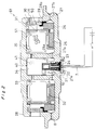
- FIG. 1 shows a sectional view of a gas generator 60 for air bag according to the present invention.
- a reference numeral 27 represents a lower casing made of an aluminum alloy which comprises an inner cylinder 27a and an outer cylinder 27b.
- a reference numeral 28 represents an upper casing also made of an aluminum alloy which comprises an inner cylinder 28a and an outer cylinder 28b.
- the inner cylinder 27a and the outer cylinder 27b are respectively opposed to the inner cylinder 28a and the outer cylinder 28b and joined by friction welding between A and B portions to form a casing.
- a sack-shaped projecting portion 27c is integrally formed with the lower casing 27 at a center thereof.
- a communication hole 27d is provided in the projecting portion 27c at a center thereof.
- orifices 33 are opened in the inner cylinder 28a of the upper casing 28.
- Diffusers 36 are opened in the outer cylinder 28b of the upper casing 28.
- the casing comprises an circular outer space 35 surrounded by the outer cylinder 27b of the lower casing 27 and the outer cylinder 28b of the upper casing 28 and a center space 34 defined by a portion surrounded by the inner cylinder 27a of the lower casing 27 and the inner cylinder 28a of the upper casing 28 and inside of the projecting portion 27c.
- a igniting agents container 40 is contained in a portion surrounded by the inner cylinder 27a of the lower casing 27 and the inner cylinder 28a of the upper casing 28 in the center space 34.
- a squib 10 is contained in a position of the projecting portion 27c in the center space 34.
- the outer space 35 is divided by an inner wall 31 having orifices 32.
- a gas generant container 50 is contained inside the inner wall 31 while a first coolant 25 located at outlets of the orifices 32, a second coolant 26 and a filter 30 sealed with a filter cover 29 are contained exterior of the inner wall 31.
- the squib 10 in the projection portion 27c is covered with an electrically insulating material 21 such as an elastomer and fixed with a calking member 27e of the lower casing 27 through a ferrite cover 22, a first keep plate 23 and a second keep plate 24.
- an electrically insulating material 21 such as an elastomer
- the electrically insulating material 21 serves as a heat insulating material too. Accordingly, exterior heat is mainly transferred to the squib 10 through a pair of lead pins 7 in case of vehicle fire or the like.
- a height of the cylinder-shaped boss 27f is higher by a distance H than the friction welded site A to avoid thermal effect on the electrically insulating material 21 due to scattering burr as welding with friction.
- a bottom of the squib 10 abuts on the igniting agents container 40 through the electrically insulating material 21.
- the explosive in the squib 10 is initiated when a predetermined electrical current is flown in a bridge which is not shown in Fig. 1 through the lead pins 7.
- a bottom of the squib is broken and then high-temperature and high-pressure gas is discharged.
- This high-temperature gas breaks the igniting agents container 40 to cause the igniting agents contained therein to be fired.
- a high-temperature gas is generated as a result of burning of the igniting agents and passes through the orifices 33 and breaks the gas generant container 50 to cause the gas generant 51 contained therein to be ignited.
- a large amount of gas is generated as a result of burning of the gas generant 51.
- the generated gas passes through the orifices 32, the first coolant 25 and the second coolant 26 where cooling and collection of residues are made, then passes through the filter 30 where mists are removed and is discharged into an air bag which is not shown through the diffusers 36.
- Fig. 3 shows an example where an initiating agents 4 and an spontaneous firing explosive composition 5 according to the present invention are aligned into a double layer structure within a magazine 8 of the squib 10.
- a portion of the squib 10 corresponding to the spontaneous firing explosive composition 5 is contained in the sack-shaped projecting portion 27c of the lower casing 27 with being coated with the electrically insulating material 21 which also serves as a heat insulating material.
- Fig. 4 shows an example where only the spontaneous firing explosive composition 5 according to the present invention is contained in the magazine 8 of a squib 11.
- Fig. 5 shows an example where an explosive bullet as the initiating agents 4 for a squib 12 and covered with the spontaneous firing explosive composition 5 according to the present invention is contained in the magazine 8 of a squib 12.
- squibs 10 and 12 shown respectively in Figs. 3 and 5 Normal operations of the squibs 10 and 12 shown respectively in Figs. 3 and 5 are as follows: first, when a predetermined electrical current is flown through electrode lead pins 7, the bridge 2 is heated, which causes the initiating agents 4 to be fired. Next, the explosive composition 5 is fired . The bottom of the squib is broken as the inside of the squib becomes high temperature and high pressure. As a result, a high-temperature, high-pressure gas is discharged. When the squib 10 or 12 is heated from outside due to, for example, an accident, the spontaneous firing explosive composition 5 is spontaneously fired at the time when the temperature within the squib reaches 165-220 °C or 165-200 °C. Next, the initiating agents 4 is fired.
- the end bottom of the squib is broken as the inside of the squib becomes high temperature and high pressure As a result, a high-temperature, high-pressure gas is discharged. Then, as described in conjunction with Figs. 1 and 2, the igniting agent container 40 is broken and then the gas generant container 50 is broken. The high-temperature, high-pressure gas is thus successively generated.
- a normal operation of the squib 11 shown in Fig. 4 is as follows: first, when a predetermined electrical current is flown through the electrode lead pins 7, the bridge 2 is heated, which causes the explosive composition 5 to be iginited. The bottom of the squib is broken as the inside of the squib becomes high temperature and high pressure. As a result, a high-temperature and high-pressure gas is discharged. When the squib 11 is heated from outside and then the temperature within the squib reaches 165-220°C or 165-200 °C, the spontaneous firing explosive composition 5 is spontaneously fired at the time. The bottom of the squib is broken as the inside of the squib becomes high temperature and high pressure.
- the spontaneous firing explosive composition in Figs. 3 through 5 is spontaneously fired at 165-220 °C or 165-200 °C. Accordingly, when the casings 27 and 28 in Figs. 1 and 2 is made of a light aluminum alloy, the spontaneous firing explosive composition is to be fired before the mechanical strength is deteriorated as the casing is heated due to firing or the like. Thus, there is no fear of breakage of the casing or scattering of broken pieces.
- the spontaneous firing explosive composition according to the present invention is contained in the igniting agents container 40 or the gas generant container 50 in Figs. 1 and 2, the squib may be left without firing. On the contrary, when the spontaneous firing explosive composition according to the present invention is contained in the squib, all explosive in the gas generator is fired.
- the spontaneous firing explosive composition is included a synthetic resins.
- the spontaneous firing explosive composition consists of carbohydrates, oxyhalogenates, metal oxides, a synthetic resins, and is to be fired stably at a low temperatures of 165-220 °C.
- Fig. 6 shows an example of an appearance of the gas generant container 50.
- the gas generant is contained in a container formed of a cup of aluminum foil.
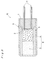
- Fig. 7 shows an example of a sectional view where the spontaneous firing explosive composition according to the present invention is contained in the gas generant container 50 as the gas generant 51 of pellets shape.
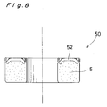
- Fig. 8 shows an example of a sectional view where the spontaneous firing explosive composition according to the present invention is contained in the gas generant container 50 as the gas generant 51 of powder.
- a reference numeral 52 represents a ceramic cushion material for use in avoiding oscillation and vibration of the gas generant.
- a gas generant is the spontaneous firing explosive composition 5 according to the present invention
- a temperature of the gas generant (spontaneous firing explosive composition) 51 contained in the gas generant container 50 reaches 165-220 °C or 165-200 °C
- the gas generant (spontaneous firing explosive composition) 51 is spontaneously fired and breaks the gas generant container 50.
- a high-temperature gas passes through the orifices 33 and breaks the igniting agents container 40 to fire the igniting agents.
- the gas generant (spontaneous firing explosive composition) 51 in Fig. 7 or 8 is spontaneously fired at 165-220°C or 165-200 °C, so that there is no fear of breakage of the casing and scattering of the broken pieces even if the lower casing 27 and the upper casing 28 in Fig. 1 is made of light aluminum alloy.
- Fig. 9 shows an example where the spontaneous firing explosive composition 5 according to the present invention is contained in the igniting agents container 40.
- Fig. 10 shows an example where the spontaneous firing explosive composition 5 according to the present invention is contained in the igniting agents container 40 along with the igniting agents 41 made of boron/potassium nitrate with a two-layer structure .
- Fig. 1 in case of the gas generator 60 having this igniting agents container 40 heated from outside due to vehicle firing or warehouse firing, and then a temperature of the spontaneous firing explosive composition 5 contained in the igniting agents container 40 reaches 165-220 °C or 165-200 °C, the spontaneous firing explosive composition 5 is spontaneously fired and breaks the igniting agents container 40. This discharges a high-temperature and high-pressure gas. The discharged gas passes through the orifices 33 and breaks the gas generant container 50 to fire the gas generant 51 contained therein. A large volume of gas is generated as a result of burning of the gas generant 51. The generated gas is passed through the first coolant 25 and the second coolant 26, and is then discharged outward through the filter 30.
- the spontaneous firing explosive composition 5 in Fig. 9 or 10 is spontaneously fired at 165-220°C or 165-200 °C, so that there is no fear of breakage of the casing and scattering of the broken pieces even if the lower casing 27 and the upper casing 28 in Fig. 1 is made of light aluminum alloy.
- a squib contained a spontaneous firing explosive composition (carbohyd rates/oxyhalogenates/metal oxides) according to the present invention comprising no synthetic resins. This squib was assessed solely, too.
- a term "part" used in the examples represents a part by weight.
- a pressure sensor 110 was attached to a SUS container 100 with a space 101 of a capacity of 10 milli-liters.
- the squib 10 was attached to a lid of the SUS container 100.
- the electrode lead pins 7 of the squib 10 were connected to a squib ignition power source and an oscillograph for current measurement.
- a terminal of the pressure sensor 110 was connected to the measurement oscillograph.
- a predetermined electrical current was flown across the squib to ignite it.
- An initiating time t (msec.) and a maximum generated pressure value Pmax. (psi) were measured.
- An initiating time t in Table 1 means a time interval from time when electrical current has finished flowing through the squib to time of starting raising the pressure.
- a spontaneous firing explosive composition was prepared as follows, 1.2 parts of super fine powder of light magnesium oxide (reagent; Wako Pure Chemical Industries Co., Ltd.) having an average particle diameter of 0.001 mm or smaller was added to and mixed with 74.8 parts of potassium chlorate (reagent; Wako Pure Chemical Industries Co., Ltd.) having an average particle diameter of 0.2 mm. After mixing, it was found that the magnesium oxide was coated on the surfaces of the potassium chlorate when observed through an optical microscope, Next, 1.0 parts of said light magnesium oxide (reagent; Wako Pure Chemical Industries Co., Ltd.) was added to and mixed with 23.0 parts of sucrose (Taito Corporation) having an average particle diameter of 0.05 mm. After mixing, it was found that the surfaces of the sucrose was coated with the magnesium oxide when observed through an optical microscope. The above mentioned total amount of potassium chlorate/magnesium oxide and sucrose/magnesium oxide were mixed with each other to obtain the spontaneous firing explosive composition.
- the squib was assembled in a following manner. A squib sheath 9 was placed in the squib cup 6 as shown in Fig. 3, in which 40 mg of the spontaneous firing explosive composition 5 was added. Subsequently, 120 mg of the initiating agents 4 (zirconium/potassium perchlorate) were placed and a squib sealing plug 1 was engaged therewith. For comparison, a explosive of sucrose/potassium chlorate with no magnesium oxide added. In addition, a squib was assembled in the same manner as those described above. Histories of the squibs were following three of types: the room temperature only, 120 °C ⁇ 100 hours and 107 °C ⁇ 400 hours. The results are given in Table 1. For comparative examples, the explosives were non-initiating in both 120 °C ⁇ 100 hours and 107 °C ⁇ 400 hours. On the contrary, no change in pressure was found for those according to the present invention.
- the squib 10 was attached to a lid of a SUS container 120 having a space 101 of a capacity of 10 milli-liters. A hole for temperature measurement was formed in the lid, in which a thermocouple was inserted to monitor temperature in the container.
- the container 120 was heated with a Bunsen burner. The container temperature at which the squib was spontaneously fired were recorded.
- the squib was as same as that used in the above mentioned examples.
- the results are given in Table 2.
- the explosives were misfired in both 120°C ⁇ 100 hours and 107 °C ⁇ 400 hours. On the contrary, those according to the present invention were all fired spontaneously at and around 200°C after the above mentioned heat aging tests.
- Fig. 1 the same squib as the one described in said examples was attached to a gas generator of an aluminum casing where the amount of the gas generant pellets 51 and the igniting agents 41 were respectively 55 gram and 1.7 gram.
- the gas generator was suspended in the air and subjected to a bonfire test with being heated by flame generated by firewood to be spontaneously fired. A heating time until spontaneous firing and a state of the gas generator after firing were observed.
- the results are given in Table 3.
- the heat aging tests of 120°C ⁇ 100 hours and 107 °C ⁇ 400 hours both resulted in casing breakage. On the contrary, those according to the present invention were approximately similar to the state of the room temperature.
- a spontaneous firing explosive composition (carbohydrates/oxyhalogenates/metal oxides based) according to the present invention contained in the gas generant.
- An spontaneous firing explosive composition was prepared as follows. 1.2 parts of super fine powder of light magnesium oxide (reagent; Wako Pure Chemical Industries Co., Ltd.) having an average particle diameter of 0.001 mm or smaller was added to and mixed with 74.8 parts of potassium chlorate (reagent; Wako Pure Chemical Industries Co., Ltd.) having an average particle diameter of 0.2 mm. After mixing, it was found that the surfaces of the potassium chlorate was coated with the magnesium oxide when observed through an optical microscope. Next, 1.0 parts of said light magnesium oxide (reagent; Wako Pure Chemical Industries Co., Ltd.) were added to and mixed with 23.0 parts of sucrose (Taito Corporation) having an average particle diameter of 0.05 mm. After mixing, it was found that the surfaces of the sucrose was coated with the magnesium oxide when observed through an optical microscope. The above mentioned total amount of potassium chlorate/magnesium oxide and sucrose/magnesium oxide were mixed with each other to obtain the spontaneous firing explosive composition.
- This spontaneous firing explosive composition was placed in a mill of which diameter is 10 mm and press-molded under a load of 500 kilo-gram. And then pellets of the gas generant were obtained. Its weight of one pellet is approximately 0.6 gram. As shown in Fig. 7, the above mentioned pellets 30 gram were placed in the gas generant container 50 and sealed as shown in Fig. 6. Twelve containers such as the above mentioned generant containers 50 were ready.
- the gas generator 60 contains the squib 10 having zirconium/potassium perchlorate 120 milli-gram, the igniting agents container 40 having the igniting agents (boron/potassium nitrate) 1.0 gram and the above mentioned gas generant container 50.
- This gas generator 60 was used for test of a pressure-time with a 60-liter tank and a heating test with firewood (bonfire test). The results are given in Table 4 and Table 6. Differences in temperature histories during the 60-liter tank pressure-time test were slight. During the bonfire test, there were no differences in temperature histories found.
- An igniting time t in Table 4 is a time interval from time when electrical current has finished flowing through the squib to time of starting raising the pressure.
- the gas generant was made of a sucrose/potassium chlorate without adding magnesium oxide.
- the gas generant without magnesium oxide was placed in a mill of which the diameter is 10 mm and press-molded under a load of 500 kilo-gram. And then pellets of the gas generant were obtained. Its weight of one pellet is approximately 0.6 gram.
- the above mentioned pellets 30 gram were placed in the gas generant container 50 and sealed as shown in Fig. 6. Twelve containers such as the above mentioned generant containers 50 were ready.
- We applied three types of temperature histories Here are: room temperature, 120 °C ⁇ 100 hours and 107 °C ⁇ 400 hours. We used four containers to each types.
- the gas generator 60 made of the aluminum casing was assembled.
- the gas generator 60 contains the squib 10 having zirconium/potassium perchlorate 120 mille-gram, the igniting agents container 40 having the igniting agents (boron/potassium nitrate) 1.0 gram and the above mentioned gas generant container 50.
- This gas generator 60 was used for test of a pressure-time with a 60-liter tank and a heating test with firewood (bonfire test). The results are given in Table 5 and Table 6.
- no gas generant was ignited with the temperature histories of 120°C ⁇ 100 hours and 107 °C ⁇ 400 hours.
- gas generation were made abnormally with the temperature histories of 120 °C ⁇ 100 hours and 107 °C ⁇ 400 hours.
- An spontaneous firing explosive composition was prepared as follows. 23.0 parts of wood powder having an average particle diameter of 0.05 mm was added to and mixed with 1.0 parts of said light magnesium oxide(reagent; Wako Pure Chemical Industries Co., Ltd.), to which 76.0 parts of potassium chlorate/magnesium oxide mixture prepared in said examples was added and mixed with each other. 24.0 parts of the above mentioned wood powder/potassium chlorate/magnesium oxide composition was mixed with 76.0 parts of spontaneous firing explosive composition based on sucrose/potassium chlorate/magnesium oxide prepared in said examples to obtain gas generant in the form of powder. As shown in Fig. 8, the above mentioned gas generant 30 gram was placed in the gas generant container 50 and sealed as shown in Fig. 6.
- the gas generator 60 made of the aluminum casing was assembled.
- the gas generator 60 contains the squib 10 having zirconium/potassium perchlorate 120 milli-gram, the igniting agent container 40 having the igniting agent (boron/potassium nitrate) 1.0 gram and the above mentioned gas generant container 50.
- This gas generator 60 was used for test of a pressure-time with a 60-liter tank and a heating test with firewood (bonfire test). The results are given in Table 7 and Table 9. Differences in temperature histories during the 60-liter tank pressure-time test were slight. During the bonfire test, there were no differences in temperature histories found.
- the gas generant was made of a wood powder/sucrose/potassium chlorate mixture without adding magnesium oxide by the same manner in the above mentioned examples 22 to 30.
- the above mentioned gas generant 30 gram was placed in the gas generant container 50 and sealed as shown in Fig. 6. Twelve containers such as the above mentioned generant containers 50 were ready.
- the gas generator 60 made of the aluminum casing was assembled.
- the gas generator 60 contains the squib 10 having zirconium/potassium perchlorate 120 milli-gram, the igniting agents container 40 having the igniting agents(boron/potassium nitrate) 1.0 gram and the above mentioned gas generant container 50.
- This gas generator 60 was used for test of a pressure-time with a 60-liter tank and a heating test with firewood (bonfire test). The results are given in Table 8 and Table 9.
- no gas generant was ignited with the temperature histories of 120°C ⁇ 100 hours and 107 °C ⁇ 400 hours.
- bonfire test gas generation were made abnormally with the temperature histories of 120 °C ⁇ 100 hours and 107 °C ⁇ 400 hours.
- a spontaneous firing explosive composition (carbohydrates/oxyhalogenates/metal oxides) according to the present invention was contained in the igniting agents 41.
- a spontaneous firing explosive composition was prepared as follows. 1.2 parts of said light magnesium oxide (reagent; Wako Pure Chemical Industries Co., Ltd.) was added to and mixed with 74.8 parts of potassium chlorate oxide(reagent; Wako Pure Chemical Industries Co., Ltd.) having an average particle diameter of 0.2 mm. After mixing, it was found that the surfaces of the potassium chlorate was coated with the magnesium oxide when observed through an optical microscope. Next, 1.0 parts of said light magnesium (reagent; Wako Pure Chemical Industries Co., Ltd.) was added to and mixed with 23.0 parts of sucrose (Taito Corporation) having an average particle diameter of 0.05 mm. After mixing, it was found that the surfaces of the sucrose was coated with the magnesium oxide when observed through an optical microscope. The above mentioned total amount of potassium chlorate/magnesium oxide and sucrose/magnesium oxide were mixed with each other to obtain the spontaneous firing explosive composition.
- the above mentioned explosive composition 1.0 gram was placed in the igniting agents container 40 and sealed. Twelve containers such as the above mentioned igniting agents containers 40 were ready. We applied three types of temperature histories. Here are: room temperature, 120°C ⁇ 100 hours and 107 °C ⁇ 400 hours. We used four containers to each types, Thereafter, as shown in Fig, 1, the gas generator 60 made of the aluminum casing was assembled.
- the gas generator 60 contains the squib 10 having zirconium/potassium perchlorate 120 milli-gram, the gas generant container 50 having the gas generant 55 gram of based on sodium azide, and the igniting agents container 40 having the above mentioned spontaneous firing explosive composition.
- This gas generator 60 was used for test of a pressure-time with a 60-liter tank and a heating test with firewood (bonfire test). The results are given in Table 10 and Table 12. Differences in temperature histories during the 60-liter tank pressure-time test were slight, During the bonfire test, there were no differences in temperature histories found.
- An igniting time t in Table 10 and Table 11 means a time interval from time when electrical current has finished flowing through the squib to time of starting raising the pressure.
- a heating time t in Table 12 means a time for the gas generator 60 to fire, Maximum pressure time means a time for pressure to become maximum.
- igniting agents 41 were made of a sucrose/potassium chlorate without adding magnesium oxide, As in the above, the igniting agents 41 without magnesium oxide were placed in the igniting agents container 40 as in said examples. Twelve containers such as the above mentioned igniting agents containers 40 were ready, We applied three types of temperature histories, That is : room temperature, 120°C ⁇ 100 hours and 107 °C ⁇ 400 hours. We used four containers to each types. Thereafter, as shown in Fig. 1, the gas generator of the same specifications as in said examples except for the igniting agents were assembled. This gas generator is used for conducting the same assessment tests as in said examples. The results are given in Table 11 and Table 12.
- the explosives were all non-ignited and the gas generant was failed to be ignored with the temperature histories of 120°C ⁇ 100 hours and 107 °C ⁇ 400 hours.
- the casings were broken down with the temperature histories of 120°C ⁇ 100 hours and 107 °C ⁇ 400 hours.
- the resultant spontaneous firing explosive compositions were subjected to measurements on the pressure maximum time and the generated pressure by using a test vessel obtained by attaching a pressure sensor to a stain less vessel having an inner volume of 1 liter, in which the spontaneous firing explosive composition 15 gram was burned in the form of powder (1-liter tank test).
- the pressure maximum time means a time interval from time when electrical current has finished flowing through the ignitor to time of raising the pressure till maximum.
- the spontaneous firing explosive compositions were applied with temperature histories of 120°C ⁇ 100 hours and 107 °C ⁇ 400 hours to determine the heat aging properties.
- a spontaneous firing temperature of the spontaneous firing explosive composition was measured by using a differential scanning calorimetry (Type DSC 220: Seiko Instruments Inc.). The results of the above test are summarized in Table 13.
- Comparative Examples 46 through 51 non-igniting were found in all after the heat aging at 120 °C for 100 hours because there were no metal oxides contained. In addition, the spontaneous firing temperature could't be measured. For the state after heat aging, no changes were found in Examples while their color of test vessel change into black-brown due to effect of heat in all Comparative Examples .
- the spontaneous firing explosive composition according to the present invention has a spontaneous firing function in a specific high-temperature range and kept a stable burning capability after the heat aging at 120 °C for 100 hours.
- a pressure sensor 110 was attached to a SUS container 100 with a space 101 of a capacity of 10 milli-liters.
- the squib 10 was attached to a lid of the SUS container 100.
- the electrode lead pins 7 of the squib 10 were connected to a squib ignition power source and an oscillograph for current measurement.
- a terminal of the pressure sensor 110 was connected to the measurement oscillograph.
- a predetermined electrical current was flown across the squib to initiate it.
- An initiating time t (msec.) and maximum pressure value Pmax. (psi.) were measured.
- An initiating time t (msec.) means a time up to start raising the pressure after an electrical current has finished flowing through the squib.
- a spontaneous firing explosive composition was prepared as follows. 1.2 parts of said super fine powder of light magnesium oxide (reagent; Wako Pure Chemical Industries Co., Ltd.) was added to and mixed with 74.8 parts of potassium chlorate (reagent; Wako Pure Chemical Industries Co., Ltd.) having an average particle diameter of 0.2 mm, After mixing, it was found that the surfaces of the potassium chlorate was coated with the magnesium oxide when observed through an optical microscope. Next, 1.0 parts of said light magnesium oxide (reagent; Wako Pure Chemical Industries Co., Ltd.) was added to and mixed with 23.0 parts of sucrose (Taito Corporation) having an average particle diameter of 0.05 mm. After mixing, it was found that the surfaces of the sucrose was coated with the magnesium oxide when observed through an optical microscope.
- the squib was assembled in a following manner. A squib sheath 9 was placed in the squib cup 6, in which the spontaneous firing explosive composition 60 milli-gram was added. Subsequently, the initiating agents 4 (zirconium/potassium perchlorate) 140 milli-gram was placed and a squib sealing plug 1 was engaged therewith. For comparison, an explosive made of sucrose/potassium chlorate/magnesium oxide with no synthetic resins, In addition, the squib was assembled in the same manner as those described above. Histories of the squib temperature were following three types: the room temperature only, 120°C ⁇ 100 hours and 107 °C ⁇ 400 hours, The results are given in Table 14. there were significant straggling on comparative examples of both 120 °C ⁇ 100 hours and 107 °C ⁇ 400 hours, On the contrary, those according to the present invention provided stable results in the initiating time as well as the generated pressure.
- the squib 10 was attached to a lid of a SUS container 120 having a space 101 of which a capacity is 10 milli-liters. A hole for temperature measurement was formed in the lid, in which a thermocouple was inserted to monitor a temperature in the container.
- the container 120 was heated with a Bunsen burner. The container temperature at which the spontaneous firing explosive composition in the squib was spontaneously fired was recorded.
- the squib was as same as that used in the above mentioned examples. The results are given in Table 15. On comparative examples, the spontaneous firing explosive composition in the squib were spontaneously fired at 200 °C or higher, and of which struggling were significant. On the contrary, those according to the present invention were all spontaneously fired at and around 180 °C after the above mentioned heat aging test with less straggling.
- a spontaneous firing explosive composition was prepared as follows. 1.2 parts of said super fine powder of light magnesium oxide (reagent; Wako Pure Chemical Industries Co., Ltd.) was added to and mixed with 74.8 parts of potassium chlorate (reagent; Wako Pure Chemical Industries Co., Ltd.) having an average particle diameter of 0.2 mm. After mixing, it was found that the surfaces of the potassium chlorate was coated with the magnesium oxide when observed through an optical microscope. Next, 1.0 parts of said light magnesium oxide (reagent; Wako Pure Chemical Industries Co., Ltd.) was added to and mixed with 23.0 parts of sucrose (Taito Corporation) having an average particle diameter of 0.05 mm. After mixing, it was found that the surface of the sucrose was coated with the magnesium oxide when observed through an optical microscope.
- This spontaneous firing explosive composition was placed in a mill of which diameter is 10 mm and press-molded under a load of 500 kilo-gram to obtain pellets of the gas generant, Weight of one pellet is approximately 0.6 gram.
- Weight of one pellet is approximately 0.6 gram.
- the above mentioned pellets 35 gram were placed in the gas generant container 50 and sealed as shown in Fig. 6. Twelve containers such as the above mentioned generant containers 50 were ready.
- We applied three types of temperature histories Here are: room temperature, 120°C ⁇ 100 hours and 107 °C ⁇ 400 hours, We used four containers to each types. Thereafter, as shown in Fig, 1, the gas generator 60 made of the aluminum casing was assembled.
- the gas generator 60 contains the squib 10 having zirconium/potassium perchlorate 120 milli-gram, the igniting agent container 40 having the igniting agent (boron/potassium nitrate) 1.0 gram and the above mentioned gas generant container 50.
- This gas generator 60 was used for test of a pressure-time with a 60-liter tank and a heating test with firewood (bonfire test). The results are given in Table 17 and Table 19. Differences in temperature histories during the 60-liter tank pressure-time test were slight. During the bonfire test, there were no differences in temperature histories found.
- An igniting time t means a time up to start raising the pressure after an electrical current has finished flowing through the squib.
- Maximum pressure time means a time for pressure to become maximum.
- a heating time t in Table 12 means a time for the gas generator 60 to fire.
- a gas generant was prepared without granulating with a silicon resin. As in the above, this was placed in a mill of which diameter is 10 mm and press-molded under a load of 500 kilo-gram to obtain pellets of the gas generant. Weight of one pellet is approximately 0.6 gram. As shown in Fig. 7, the above mentioned pellets 35 gram were placed in the gas generant container 50 and sealed as shown in Fig. 6. Twelve containers such as the above mentioned generant containers 50 were ready. We applied three types of temperature histories. Here are: room temperature, 120°C ⁇ 100 hours and 107 °C ⁇ 400 hours. We used four containers to each types. Thereafter, as shown in Fig, 1, the gas generator 60 made of the aluminum casing was assembled.
- the gas generator 60 contains the squib 10 having zirconium/potassium perchlorate 120 milli-gram, the igniting agents container 40 having the igniting agents(boron/potassium nitrate) 1.0 gram and the above mentioned gas generant container 50.
- This gas generator 60 was used for test of a pressure-time with a 60-liter tank and a heating test with firewood (bonfire test). The results are given in Table 18 and Table 19. During the 60-liter tank pressure-time test, there were a significant struggling in results. During the bonfire test, filter breakage was caused.
- a spontaneous firing explosive composition was prepared as follows. 23.0 parts of wood powder having an average particle diameter of 0.05 mm was added to and mixed with 1.0 parts of said light magnesium oxide (reagent; Wako Pure Chemical Industries Co., Ltd.), to which 76.6 parts of potassium chlorate/magnesium oxide mixture prepared in said examples was added and mixed with each other, to which 5.0 parts of silicon resin was added. The mixture was kneaded over 30 minutes.
- the gas generator 60 made of the aluminum casing was assembled.
- the gas generator 60 contains the squib 10 having zirconium/potassium perchlorate 120 milli-gram, the igniting agents container 40 having the igniting agents(boron/potassium nitrate) 1.0 gram and the above mentioned gas generant container 50.
- This gas generator 60 was used for test of a pressure-time with a 60-liter tank and a heating test with firewood (bonfire test). The results are given in Table 20 and Table 22. Differences in temperature histories during the 60-liter tank pressure-time test were slight. During the bonfire test, there were no differences in temperature histories found.
- a wood powder/sucrose/potassium chlorate/magnesium oxide mixture was prepared as a gas generant in the same manner and same ratio of the above mentioned examples 22 to 30 without silicon resin.
- the above mentioned gas generant 35 gram was placed in the gas generant container 50 and sealed as shown in Fig. 6. Twelve containers such as the above mentioned generant containers 50 were ready.
- We applied three types of temperature histories Here are: room temperature, 120°C ⁇ 100 hours and 107 °C ⁇ 400 hours.
- the gas generator 60 made of the aluminum casing was assembled.
- the gas generator 60 contains the squib 10 having zirconium/potassium perchlorate 120 milli-gram, the igniting agents container 40 having the igniting agents(boron/potassium nitrate) 1.0 gram and the above mentioned gas generant container 50.
- This gas generator 60 was used for test of a pressure-time with a 60-liter tank and a heating test with firewood (bonfire test). The results are given in Table 21 and Table 22. During the 60-liter tank pressure-time test, there were a significant struggling in results. During the bonfire test, filter breakage was caused.
- a spontaneous firing explosive composition according to the present invention (carbohydrates/oxyhalogenates/metal oxides/synthetic resins) was contained in the igniting agents.
- a spontaneous firing explosive composition was prepared as follows. 1.2 parts of said light magnesium oxide (reagent; Wako Pure Chemical Industries Co., Ltd.) was added to and mixed with 74.8 parts of potassium chlorate (reagent; Wako Pure Chemical Industries Co., Ltd.) having an average particle diameter of 0.2 mm. After mixing, it was found that the surfaces of the potassium chlorate were coated with the magnesium oxide when observed through an optical microscope, Next, 1.0 parts of said light magnesium oxide (reagent; Wako Pure Chemical Industries Co., Ltd.) were added to and mixed with 23.0 parts of sucrose (Taito Corporation) having an average particle diameter of 0.05 mm. After mixing, it was found that the surfaces of the sucrose were coated with the magnesium oxide when observed through an optical microscope.
- the above mentioned spontaneous firing explosive composition 2.0 gram was placed in the igniting agents container 40 and sealed. Twelve containers such as the above mentioned igniting agents containers 40 were ready. We applied three types of temperature histories. Here are: room temperature, 120°C ⁇ 100 hours and 107 °C ⁇ 400 hours. We used four containers to said each types. Thereafter, as shown in Fig. 1, the gas generator 60 made of the aluminum casing was assembled. The gas generator 60 contains the squib 10 having zirconium/potassium perchlorate 120 milli-gram, the gas generant container 50 having the gas generant based on sodium azide 55 gram, and the igniting agents container 40 having the above mentioned spontaneous firing explosive composition.
- This gas generator 60 was used for test of a pressure-time with a 60-liter tank and a heating test with firewood (bonfire test). The results are given in Table 23 and Table 25. Differences in temperature histories during the 60-liter tank pressure-time test were slight. During the bonfire test, there were no differences in temperature histories found.
- An igniting time t (msec.) means a time up to start raising the pressure after an electrical current has finished flowing through the squib.
- Maximum pressure time means a time for pressure to become maximum.
- a heating time t means a time for the gas generator 60 to fire.
- a sucrose /potassium chlorate/magnesium oxide was prepared as igniting agents without synthetic resins.
- This igniting agents were placed in the igniting agents container in the same manner of said examples, Twelve containers such as the above mentioned igniting agents containers 40 were ready.
- the gas generator was assembled with the same specifications of said examples except for the igniting agents. This gas generator is used to conduct the same assessment tests as in said examples. The results are given in Table 24 and Table 25.
- bonfire test filter breakage was caused.
- the mixture was made by means of two steps mixing. At first, carbohydrates and potassium chlorate are respectively mixed up with metal oxides and then these mixtures are mixed together. Thereafter, the synthetic resins were added thereto, which was kneaded and granulated over 30 minutes and was stood at a room temperature over 48 hours for curing the resins.
- the resultant spontaneous firing explosive compositions were subjected to measurements on the generated pressure and the time when said generated pressure rises up till maximum by using a test vessel obtained by attaching a pressure sensor to a stainless vessel having an inner volume of 1 liter, in which the spontaneous firing explosive composition 8 gram was burned in the form of granule (1-liter tank test).
- a squib having firing agent 0.6 gram contained of a boron/potassium nitrate and lead styphnate fuse heads were used.
- the igniting time means a time interval from time when electrical current has finished flowing through the squib to time of starting raising the pressure.
- the spontaneous firing explosive compositions were applied with temperature history of 120°C ⁇ 100 hours to determine the heat aging properties.
- a spontaneous firing temperature of the spontaneous firing explosive compositions was measured by using a differential thermal analyzer (Type DSC 220: Seiko Instruments Inc.). The results of the above tests are summarized in Table 26.
- Comparative Examples 46 through 48 the spontaneous firing temperatures were increased because there were no synthetic resins contained. The spontaneous firing temperatures were further increased after the heat aging at 120 °C for 100 hours. In Comparative Examples 49 through 51, non-igniting were found after the heat aging at 120 °C for 100 hours because there were no metal oxides contained. In addition, the spontaneous firing temperature could't be measured. For the state after heat aging, no changes were found in Examples and Comparative Examples 46 through 48 while Comparative Examples 49 through 51 resulted in color change into black-brown due to effect of heat.
- the spontaneous firing explosive composition according to the present invention has a spontaneous firing function in a specific high-temperature range and kept a stable burning capability after the heat aging at 120 °C for 100 hours.
- the gas generator for air bag requires no preparation of a specific container space in a casing by means of containing a spontaneous firing explosive composition comprising carbohydrates, oxyhalogenates and metal oxides in at least one of the squib, the igniting agents and the gas generant, and it is thus possible to maintain stable properties for a long time with safety and a spontaneous firing function at a low temperature up to 220 °C without particular considerations on the heat conductivity between the casing, so that it is optimum as the gas generator with the casing of a light alloy material or the like of which mechanical strength will be deteriorated when being subjected to high temperature environments.
- a spontaneous firing explosive composition consisting of carbohydrates, oxyhalogenates, metal oxides and synthetic resins.
- the squib contains the spontaneous firing explosive composition according to the present invention as compared with a case where it is contained in the gas generant or the firing agents, this eliminates a fear of the explosive left in the casing without igniting of the squib after the spontaneous firing of said explosive composition.
- a spontaneous firing explosive composition also serving as initiating agents
- the bridge wire contacting therewith is corroded due to acidic substances generated as a result of deterioration with time. So, there's a fear for an incorrect operation because of the squib not initiated upon a normal operation. While in case of the present invention, there's no fear such as said trouble.
- the present invention can find various applications as the squib having the spontaneous firing function.
- the gas generant contains the spontaneous firing explosive composition according to the present invention, no toxic gas is generated after it absorbs water as compared with conventional ones based on sodium azide. It can be a gas generator containing a novel gas generant which is capable of maintaining stable properties during exposure to high temperature environments for a long time and which has an adequate burning rate in a normal operation.
- the igniting agents contains the spontaneous firing explosive composition according to the present invention, this is possible to obtain a more excellent high-temperature stability and a more sufficient burning rate than ones of the prior art such as a spontaneous firing explosive composition also serving as igniting agents.
- the spontaneous firing explosive composition has a spontaneous firing property in temperatures range of 165-220 °C or of 165-200°C.
- the carbohydrates is a gaseous component and the oxyhalogenates is an oxygen supplying component.
- a firing temperature in a relatively low temperatures range of 165-220 °C or of 165-200°C may be selected depending on combinations of the two.
- the metal oxides is a heat stabilizer and the synthetic resin is a binder for use in granulating the spontaneous firing explosive composition.
Abstract
Description
- The present invention relates to a gas generator for air bag with a spontaneous firing function which fires at a predetermined temperature to prevent breakdown of a casing when the gas generator for air bag is heated by, for example, flame from outside. And also, The present invention relates to a squib suitable for a gas generator with a spontaneous firing function.
- Conventionally, a passive safety device for a vehicle is known that inflates an air bag with gas generated by a gas generator to ensure safety of an occupant when a vehicle is involved in collision. The gas generator comprises a gas generant, an igniting agent for igniting said gas generant and a squib for initiating said igniting agent which are contained in a casing. It is not always necessary to coexist the squib with the igniting agent, and either one of them is used as a case may be. In such a case, one has a function of the other. In addition, said casing is typically made of a light alloy material such as an aluminum alloy with demands for weight reduction.
- Light alloy materials are reduced in mechanical strength when heated to a high temperature. Accordingly, a gas generator in which such material is used for the casing will cause no problem in a normal case where the igniting agent is initiated by the squib upon collision and the gas generant is then ignited to generate gas. However, when heat is applied from outside on fire in a vehicle or a warehouse that is not expected in a normal condition, in this event, if a spontaneous firing temperature of the igniting agent or the gas generant is higher than a temperature at which the mechanical strength of the casing is deteriorated, firing is caused after the mechanical strength of the casing is deteriorated. As a result, the casing is broken due to the pressure caused within the gas generator with a risk of its scattering as small pieces.
- Against this problem, U.S. Patent No. 4,561,675 discloses a technique relating to an auto ignition device. The an auto ignition device has a primary firing agent that will fire spontaneously at a temperature of approximately 177°C at which the mechanical strength is not deteriorated in a metal container. The metal container is a single independent member made of a metal foil and fixed to an inside of a casing of a gas generator with a heat resistant adhesive or a cushion. And a firing direction of the primary firing agent is directed to a igniting agent or a gas generant that fire at a temperature of approximately 343 °C.
- In addition, Japanese Patent Laid Open No: 2-74441 discloses a technique relating to an auto ignition device. The auto ignition device has a primary firing agent that will fire spontaneously at and around a temperature of approximately 160 °C to 180 °C. The primary firing agent casing is inserted to an opening portion of a casing for a gas generator through an insulating material.
- Further, Japanese Patent Laid Open No. 5-229397 discloses a technique relating to another auto ignition device. This auto ignition device applies a spontaneous firing agent to an explosive within a squib. The a spontaneous firing agent comprises sulfur-containing binder/sodium perchlorate as a major component that fire spontaneously in 3 minutes at 150-300°C .
- Typical gas generants apply agents based on sodium azide. These agents have an adequate burning rate and a long-term stability when being subjected to a high or low temperature environments. An spontaneous firing temperature thereof is, however, as high as 400 °C or higher. The mechanical strength of the light alloy material such as an aluminum alloy is significantly reduced at that temperature, so that the casing will be broken.
- In addition, the igniting agent is typically sealed in an igniting agent container. The igniting agents apply mixtures of boron and potassium nitrate, which will be fired spontaneously at approximately 500 °C. The mechanical strength of the light alloy material such as an aluminum alloy is significantly reduced at that temperature.
- Typical squib has a structure in which an explosive is filled within a squib cup of a cylindrical shape with a bottom, which the cup is sealed with a squib plug having a bridge wire for heating which is connect to exterior through a couple of lead pins and the explosive contacts with the bridge wire. The explosive filled within the squib commonly apply mixtures of perchlorate and an organic material or metal powder by the considerations of good initiatability and stability. When heated suddenly from outside, lead trinitroresorcinate/potassium perchlorate for example will be fired spontaneously at approximately 270 °C while zirconium/potassium perchlorate will be fired spontaneously at approximately 350 °C. As other explosives to be filled in the squib, U.S. Patent No. 3,773,351 discloses those comprising sucrose and potassium chlorate.
- In the gas generators disclosed in said U.S. Patent No. 4,561,675 and Japanese Patent Laid Open No. 2-74441, there is a disadvantage that it is necessary to form a containing portion specifically for the auto ignition device in the gas generator. In the gas generator disclosed in Japanese Patent Laid Open No. 5-229397, the spontaneous firing material also serving as the igniting agent is applied to the explosive for the ignitor. The bridge wire contacting therewith is corroded due to acidic substances generated as a result of deterioration with time. There's thus some fear of incorrect operation with the ignitor not initiated upon a normal operation. The squib disclosed in U.S. Patent No. 3,773,351 uses the explosive comprising the sucrose and the potassium chlorate, so that it apparently has an spontaneous firing capability at and around 180°C. However, thermal stability is not good. More specifically, it does not pass a heat aging test criteria at and around 100°C such as 107°C × 400 hours, so that it cannot be applied in practice. In addition, spontaneous firing materials conventionally used are lack of high-temperature stability. Further, those serving also as the igniting agents have a disadvantage of lacking a necessary burning rate.
- In particular, those with the squib containing the spontaneous firing material has such a structure that the squib is contained within the gas generator, which makes heat be less likely to be transferred. As a result, there is a disadvantage that it will not be fired spontaneously in a predetermined temperature range in response to application of heat from outside. This problem is the one that may be caused in a case where the spontaneous firing material is contained in the gas generant or the igniting agents.
- The present invention is made with respect to these problems inherent to the prior art, and an object thereof is to provide a safe and positive gas generator for air bag which is to be fired spontaneously in a predetermined temperature region in response to application of heat from outside even when the gas generator for use in deploying an air bag as a passive safety device contains a spontaneous firing material in at least one of a squib, an igniting agents and a gas generant, and which maintains stable properties when exposed and being subjected to a high temperature environments for a long time.
- In addition, it is also directed to provide an optimum squib incorporated in such a gas generator for air bag.
- A gas generator for air bag according to the present invention directed to achieve the above mentioned object comprises a spontaneous firing explosive composition, which at least one of a squib, an igniting agent and a gas generant contained in a casing formed of a light alloy material includes. The spontaneous firing explosive composition consists of carbohydrates, oxyhalogenates and metal oxides and has a spontaneous firing property in a temperature range of 165-220°C. As a spontaneous firing explosive composition is in environments where heat is less likely to be transferred from its surroundings, a synthetic resins is further added. In that case the spontaneous firing explosive composition consists of carbohydrates, oxyhalogenates, metal oxides and a synthetic resins. This may have a spontaneous firing property in a lower temperature range of 165-200°C. In addition, the above mentioned explosive composition that is contained in either one of the squib, the igniting agent and the gas generant will be fired spontaneously in the above mentioned temperature range before a mechanical strength of the casing is deteriorated due to heating from outside.
- The carbohydrates in said spontaneous firing explosive composition is a gasifying component, the oxyhalogenates is an oxygen supplying component, the metal oxides is a heat aging agents (thermal stabilizer), and the synthetic resins is a component contributing to improvement of a heat conductivity between these explosive composition particles. Accordingly, an spontaneous firing temperature of 165-220°C or a lower spontaneous firing temperature of 165-200 °C may be selected optionally by means of combining them.
- In particular, a gas generator for air bag mounted on a vehicle may be stood at a high-temperature position for a long time such as an outdoor parking place in summer or a tropical area. Accordingly, a high-temperature stability is essential. The one contributing to this thermal stability is said metal oxides. In particular, the thermal stability is improved by means of coating carbohydrates or/and oxyhalogenates particles to avoid direct contact between them. In addition, a synthetic resins has an effect of decreasing a spontaneous firing temperature by means of contacting intimately the above mentioned explosive composition particles with each other so as to improve the heat conductivity between the explosive composition particles.
- To achieve a desired spontaneous firing temperature of 165-220°C or 165-200 °C as well as an adequate burning rate, carbohydrates is preferably 95.0-1.0% by weight, oxyhalogenates is preferably 95.0-1.0% by weight and metal oxides is preferably 30.0-0.01% by weight. A synthetic resins, if added thereto, is preferably 0.05 to 20.0% by weight. This composition ratio may be varied within the above mentioned composition range depending on a burning rate suitable for a desired part of the gas generator, based on a stoichiometric ratio required for burning carbohydrates and oxyhalogenates. In particular, metal oxides is preferably 30.0-0.01% by weight and more preferably 10.0-1.0% by weight. This may be varied advantageously to adjust the burning rate depending on an internal structure of the gas generator used. With carbohydrates out of this range, the burning rate will be abnormal. With oxyhalogenates out of this range, the spontaneous firing function will be deteriorated. With metal oxides out of this range, the heat aging property and the spontaneous firing function will be deteriorated. If the synthetic resins which adjust the heat conductivity between the explosive composition particles is out of this range, a spontaneous firing temperature will change significantly depending on a degree of mixing.
- A particle diameter of carbohydrates, oxyhalogenates and metal oxides significantly affects a positive firing and the high-temperature stability. An average particle diameter of carbohydrates is preferably 0.5 mm to 0.0001 mm. An average particle diameter of oxyhalogenates is preferably 1.0 mm to 0.0001 mm. A particle diameter of metal oxides is preferably 0.5 mm or smaller. With carbohydrates having the particle diameter of out of this range, the heat aging property will be deteriorated. With oxyhalogenates having the particle diameter of out of this range, the burning rate will be abnormal. With metal oxides having the particle diameter of out of this range, the heat aging property and the spontaneous firing function will be deteriorated. In particular, the particle diameter of metal oxides is preferably 1/10 or smaller than the particle diameter of carbohydrates.
- It is possible to ensure the positive firing and the high-temperature stability when the average particle diameter of metal oxides is 1/10 or smaller than the average particle diameter of at least one of carbohydrates and oxyhalogenates and when at least one of carbohydrates and oxyhalogenates is coated with metal oxides. A method of coating may be as follows: At first, carbohydrates is mixed with metal oxides to coat metal oxides on a surface of carbohydrates. In another vessel, oxyhalogenates may be mixed with metal oxides to coat metal oxides on a surface of oxyhalogenates. Subsequently, they are mixed with each other. This operation improves the high-temperature stability. The burning rate can be adjusted by an amount of coating.
- When the average particle diameters of the individual components are all 0.05 mm or smaller, these three components may be mixed simultaneously.
- Of the individual components, applicable carbohydrates may be a single or a mixture of sucrose, lactose, glucose, powder cellulose, dextrin and wood powder. It is preferable to use sucroseas the one having the preferable spontaneous firing temperature of 165-200 °C or 165-220 °C.
- Of the individual components, applicable oxyhalogenates include chlorates and perchlorates such as potassium chlorate, potassium perchlorate, sodium chlorate, sodium perchlorate, barium chlorate and barium perchlorate; bromates and perbromates such as potassium bromate, potassium perbromate, sodium bromate and sodium perbromate; and iodates and periodates such as potassium iodate, potassium periodate, sodium iodate and sodium periodate. Chlorates and perchlorates are particularly preferable by the consideration of easy handling. Potassium chlorate and potassium perchlorate are more preferable.
- Of the individual components, applicable metal oxides include magnesium oxide, calcium oxide, zinc oxide, potassium oxide, sodium oxide and cesium oxide. Magnesium oxide, calcium oxide and zinc oxide are preferable by the consideration of easy handling. In addition, light magnesium oxide is particularly preferable in view of its fine and uniform particle diameter.
- Of the individual components, applicable synthetic resins include silicon resins, urethane resins, polyesters, acrylic resins and butyl rubbers. A one component room temperature vulcanizing silicone resin is particularly preferable by the considerations of easy handling and thermal stability. It is noted that granulation is made by means of mixing carbohydrates, oxyhalogenates and metal oxides with each other, to which the synthetic resins is added.
- In particular, when the spontaneous firing explosive composition having the above mentioned components is contained in the gas generant, it may be subjected to making tablet or formed into pellets by using an adequate binder to adjust the burning rate, if necessary. In addition, it may be possible to add adequately inorganic powder such as talc, alumina oxide and silicon dioxide as well as organic powder such as wood powder, synthetic resins powder and rosin powder to adjust the burning rate.
- In particular, as an aspect of containing the spontaneous firing explosive composition having the above mentioned components in the squib, it may contact directly with the bridge wire. However, in a case where an extremely short firing time is preferable, it is preferable to form a layer structure where an initiating agent is contacted with the bridge wire, and the spontaneous firing explosive composition having the above mentioned components contacts with that initiating agents. Such squib is a single product applicable generally to a part where a spontaneous firing function is required.
- As such initiating agent, metal powder/KClO₄, diazodinitrophenol (DDNP), tetracene/lead trinitroresorcinate, lead trinitroresorcinate/KClO₄ and lead styphnate/KClO₃ may be used. Metal powder/KClO₄ is preferable by the considerations of thermal stability and good initiatability.
- The metal powder may be a single or a combination of zirconium, tungsten, titanium, aluminum, magnesium, iron, nickel and copper. In view of good initiatability, a single zirconium or a mixture of zirconium and tungsten is preferable.
- In a gas generator for air bag where such squib is held within a casing formed of a light metal material such as aluminum alloy, the gas generator for air bag comprising said squib having a layer structure consisting of an initiating agent contacted with the bridge wire and an spontaneous firing explosive composition contacted with said initiating agent, the spontaneous firing explosive composition being made of carbohydrates, oxyhalogenates, metal oxides and a synthetic resins, and a portion of the squib corresponding to the spontaneous firing explosive composition being exposed within said casing in a no good contact condition with said casing. More specifically, essentials of the squib formed of the above mentioned spontaneous firing explosive composition containing the synthetic resins are not required to be contacted well with the casing so as to improve the heat conductivity between the casing. Accordingly, an attachment structure for the squib to the casing can be simplified.
- In addition, the casing of gas generator is made of a light metal material such as aluminum alloy, which is formed with an upper casing member and a lower casing member having an inner cylinder and an outer cylinder respectively, which are opposed to and frictional welded with each other corresponding to said inner cylinders and outer cylinders each other, and then a center space within said inner cylinder and an outer space surrounded by said inner cylinder and said outer cylinder are made. The present invention of a gas generator has a squib of which surface coated with an electrically insulating material, being inserted into said casing and fixed thereto, and the spontaneous firing explosive composition consisting of carbohydrates, oxyhalogenates, metal oxides and a synthetic resins being contained in the squib. Even when the heat conductivity to the squib is restricted by the electrically insulating material, the spontaneous firing function is not deteriorated. When said squib is inserted into a cylindrical-shaped boss projected from said casing into said center space and fixed thereto, it is preferable that said cylindrical-shaped boss is larger in height than the portion of said friction welding to avoid thermal effects on the squib upon welding.
- The squib, the igniting agents and the gas generant in the gas generator for air bag are all have their own unique firing functions. The gas generator is subjected to a high temperature environments during summer or the like, and is mounted on a vehicle for a long time of many years. Accordingly, a high-temperature stability without deteriorating the firing function is required, which the high-temperature stability can be achieved with the metal oxides in the above mentioned explosive composition. The above mentioned spontaneous firing explosive composition contained in either one of the squib, the igniting agent and the gas generant is fired by its spontaneous firing function before the mechanical strength of the casing of the gas generator is deteriorated significantly upon vehicle fire or a warehouse fire. This firing is similar to a normal igniting upon such as a collision, and breakage of the casing is thus avoided. This spontaneous firing function can be kept by the metal oxides in the above mentioned spontaneous firing explosive composition even when being subjected to a high temperature environments during summer for many years. More specifically, a state where carbohydrates and oxyhalogenates are separated stably is ensured by the metal oxides, and then carbohydrates melts at a predetermined spontaneous firing temperature and reaches the oxohalogenates for firing.
- When the above mentioned spontaneous firing explosive composition is contained in the squib, the igniting agents or the gas generant, at first an exterior heat is transferred from outside to the squib, the igniting agent or the gas generant and then said explosive composition to be heated. Because of such indirect heating, the exterior heat may be less transferred depending on environments of the above mentioned explosive composition. In such a case, carbohydrates and oxyhalogenates are stably separated by the metal oxides while a state of carbohydrates's melt is not stable. So that, a straggling in spontaneous firing temperature is made. A synthetic resins serves to reduce the straggling and in turn to reduce the spontaneous firing temperature. The synthetic resins forms an adequate bridge among carbohydrates, oxyhalogenates and metal oxides. The carbohydrates is molten stably by heat conductivity via this bridge and reaches the oxyhalogenates passing through the metal oxides and the synthetic resins, so that spontaneous firing is caused. To ensure such phenomenon, it is desirable that the metal oxides has a predetermined particle diameter and contained at a predetermined amount, and that the synthetic resins is also contained at a predetermined amount. However, the synthetic resins may be omitted when the heat conductivity to the spontaneous firing explosive composition can be considered well.
-
- Fig. 1 is a sectional view of a gas generator for air bag according to the present invention;
- Fig. 2 is a sectional view of a gas generator for air bag according to the present invention;
- Fig. 3 is a sectional view of a squib containing a spontaneous firing explosive composition according to the present invention;
- Fig. 4 is a sectional view of a squib containing a spontaneous firing explosive composition according to the present invention;
- Fig. 5 is a sectional view of a squib containing a spontaneous firing explosive composition according to the present invention;
- Fig. 6 is a perspective view of a gas generant container;
- Fig. 7 is a sectional view of a gas generant container, in which pellets of a gas generant of a spontaneous firing explosive composition according to the present invent ion are contained;
- Fig. 8 is a sectional view of a gas generant container, in which powder of a gas generant of a spontaneous firing explosive composition according to the present invention is contained;
- Fig. 9 is a sectional view of a igniting agents container, in which an igniting agents of a spontaneous firing explosive composition according to the present invention is contained;
- Fig. 10 is a sectional view of an igniting agents container, in which a firing agents of a spontaneous firing explosive composition according to the present invention is contained;
- Fig. 11 is a view illustrating a squib containing a spontaneous firing explosive composition according to the present invention being attached to an pressure tester; and
- Fig. 12 is a view illustrating a squib containing a spontaneous firing explosive composition according to the present invention being attached to an initiating tester.
- An example of a gas generator is described with reference to the drawing, in which the above mentioned squib, igniting agents and gas generant are contained. While one of the squib and the igniting agents may be omitted, the following description is made in conjunction with a case where both of them are contained. Fig. 1 shows a sectional view of a
gas generator 60 for air bag according to the present invention. - In the
gas generator 60 for air bag in Fig. 1, areference numeral 27 represents a lower casing made of an aluminum alloy which comprises aninner cylinder 27a and anouter cylinder 27b. Areference numeral 28 represents an upper casing also made of an aluminum alloy which comprises aninner cylinder 28a and anouter cylinder 28b. Theinner cylinder 27a and theouter cylinder 27b are respectively opposed to theinner cylinder 28a and theouter cylinder 28b and joined by friction welding between A and B portions to form a casing. In addition, a sack-shaped projectingportion 27c is integrally formed with thelower casing 27 at a center thereof. Acommunication hole 27d is provided in the projectingportion 27c at a center thereof. Further,orifices 33 are opened in theinner cylinder 28a of theupper casing 28.Diffusers 36 are opened in theouter cylinder 28b of theupper casing 28. - As mentioned above, the casing comprises an circular
outer space 35 surrounded by theouter cylinder 27b of thelower casing 27 and theouter cylinder 28b of theupper casing 28 and acenter space 34 defined by a portion surrounded by theinner cylinder 27a of thelower casing 27 and theinner cylinder 28a of theupper casing 28 and inside of the projectingportion 27c. A ignitingagents container 40 is contained in a portion surrounded by theinner cylinder 27a of thelower casing 27 and theinner cylinder 28a of theupper casing 28 in thecenter space 34. Asquib 10 is contained in a position of the projectingportion 27c in thecenter space 34. Theouter space 35 is divided by aninner wall 31 havingorifices 32. Agas generant container 50 is contained inside theinner wall 31 while afirst coolant 25 located at outlets of theorifices 32, asecond coolant 26 and afilter 30 sealed with afilter cover 29 are contained exterior of theinner wall 31. - In particular, the
squib 10 in theprojection portion 27c is covered with an electrically insulatingmaterial 21 such as an elastomer and fixed with a calkingmember 27e of thelower casing 27 through aferrite cover 22, afirst keep plate 23 and asecond keep plate 24. When thesquib 10 covered with the electrically insulatingmaterial 21, the electrically insulatingmaterial 21 serves as a heat insulating material too. Accordingly, exterior heat is mainly transferred to thesquib 10 through a pair oflead pins 7 in case of vehicle fire or the like. - As shown in Fig. 1, to insert the
squib 10 into the projectingportion 27c through the electrically insulatingmaterial 21, an accuracy of molding of the electrically insulatingmaterial 21 is required to a certain degree. With this respect, as in a gas generator 61 for air bag shown in Fig. 2, the sack-shaped projecting portion is replaced by a cylinder-shapedboss 27f. Most of portions of the electrically insulatingmaterial 21 and thesquib 10 are projected into a position surrounded by theinner cylinder 27a of thelower casing 27 and theinner cylinder 28a of theupper casing 28 to provide easier assembly. In such a case, a height of the cylinder-shapedboss 27f is higher by a distance H than the friction welded site A to avoid thermal effect on the electrically insulatingmaterial 21 due to scattering burr as welding with friction. In addition, a bottom of thesquib 10 abuts on the ignitingagents container 40 through the electrically insulatingmaterial 21. - A normal operation of these
gas generator 60 and 61 for air bag is described. First, the explosive in thesquib 10 is initiated when a predetermined electrical current is flown in a bridge which is not shown in Fig. 1 through the lead pins 7. A bottom of the squib is broken and then high-temperature and high-pressure gas is discharged. This high-temperature gas breaks the ignitingagents container 40 to cause the igniting agents contained therein to be fired. A high-temperature gas is generated as a result of burning of the igniting agents and passes through theorifices 33 and breaks thegas generant container 50 to cause thegas generant 51 contained therein to be ignited. A large amount of gas is generated as a result of burning of thegas generant 51. The generated gas passes through theorifices 32, thefirst coolant 25 and thesecond coolant 26 where cooling and collection of residues are made, then passes through thefilter 30 where mists are removed and is discharged into an air bag which is not shown through thediffusers 36. - Fig. 3 shows an example where an initiating
agents 4 and an spontaneous firingexplosive composition 5 according to the present invention are aligned into a double layer structure within amagazine 8 of thesquib 10. When thesquib 10 is held in a manner as shown in Fig. 1, a portion of thesquib 10 corresponding to the spontaneous firingexplosive composition 5 is contained in the sack-shaped projectingportion 27c of thelower casing 27 with being coated with the electrically insulatingmaterial 21 which also serves as a heat insulating material. Fig. 4 shows an example where only the spontaneous firingexplosive composition 5 according to the present invention is contained in themagazine 8 of asquib 11. Fig. 5 shows an example where an explosive bullet as the initiatingagents 4 for asquib 12 and covered with the spontaneous firingexplosive composition 5 according to the present invention is contained in themagazine 8 of asquib 12. - Normal operations of the
squibs bridge 2 is heated, which causes the initiatingagents 4 to be fired. Next, theexplosive composition 5 is fired . The bottom of the squib is broken as the inside of the squib becomes high temperature and high pressure. As a result, a high-temperature, high-pressure gas is discharged. When thesquib explosive composition 5 is spontaneously fired at the time when the temperature within the squib reaches 165-220 °C or 165-200 °C. Next, the initiatingagents 4 is fired. The end bottom of the squib is broken as the inside of the squib becomes high temperature and high pressure As a result, a high-temperature, high-pressure gas is discharged. Then, as described in conjunction with Figs. 1 and 2, the ignitingagent container 40 is broken and then thegas generant container 50 is broken. The high-temperature, high-pressure gas is thus successively generated. - A normal operation of the
squib 11 shown in Fig. 4 is as follows: first, when a predetermined electrical current is flown through the electrode lead pins 7, thebridge 2 is heated, which causes theexplosive composition 5 to be iginited. The bottom of the squib is broken as the inside of the squib becomes high temperature and high pressure. As a result, a high-temperature and high-pressure gas is discharged. When thesquib 11 is heated from outside and then the temperature within the squib reaches 165-220°C or 165-200 °C, the spontaneous firingexplosive composition 5 is spontaneously fired at the time. The bottom of the squib is broken as the inside of the squib becomes high temperature and high pressure. As a result, a high-temperature and high-pressure gas is discharged. Then, as described in conjunction with Figs. 1 and 2, the ignitingagents container 40 is broken and then thegas generant container 50 is broken. The high-temperature and high-pressure gas is thus successively generated. - As mentioned above, the spontaneous firing explosive composition in Figs. 3 through 5 is spontaneously fired at 165-220 °C or 165-200 °C. Accordingly, when the
casings agents container 40 or thegas generant container 50 in Figs. 1 and 2, the squib may be left without firing. On the contrary, when the spontaneous firing explosive composition according to the present invention is contained in the squib, all explosive in the gas generator is fired. - In particular, as shown in Figs. 1 and 2, when the heat conductivity to the
squib 10 is restricted by theelectrically insulating material 21 or a projection from the container, it is preferable that the spontaneous firing explosive composition is included a synthetic resins. In this case, the spontaneous firing explosive composition consists of carbohydrates, oxyhalogenates, metal oxides, a synthetic resins, and is to be fired stably at a low temperatures of 165-220 °C. - Fig. 6 shows an example of an appearance of the
gas generant container 50. The gas generant is contained in a container formed of a cup of aluminum foil. - Fig. 7 shows an example of a sectional view where the spontaneous firing explosive composition according to the present invention is contained in the
gas generant container 50 as thegas generant 51 of pellets shape. Fig. 8 shows an example of a sectional view where the spontaneous firing explosive composition according to the present invention is contained in thegas generant container 50 as thegas generant 51 of powder. In Figs. 7 and 8, areference numeral 52 represents a ceramic cushion material for use in avoiding oscillation and vibration of the gas generant. - In Fig. 1, In case of the
gas generator 60 having thisgas generant container 50 of which a gas generant is the spontaneous firingexplosive composition 5 according to the present invention, and when thegas generant container 50 is heated from outside due to vehicle firing or warehouse firing and then a temperature of the gas generant (spontaneous firing explosive composition) 51 contained in thegas generant container 50 reaches 165-220 °C or 165-200 °C, the gas generant (spontaneous firing explosive composition) 51 is spontaneously fired and breaks thegas generant container 50. A high-temperature gas passes through theorifices 33 and breaks the ignitingagents container 40 to fire the igniting agents. At the same time, it is passed through thefirst coolant 25 and thesecond coolant 26, and is then discharged outward through thefilter 30. The gas generant (spontaneous firing explosive composition) 51 in Fig. 7 or 8 is spontaneously fired at 165-220°C or 165-200 °C, so that there is no fear of breakage of the casing and scattering of the broken pieces even if thelower casing 27 and theupper casing 28 in Fig. 1 is made of light aluminum alloy. - Fig. 9 shows an example where the spontaneous firing
explosive composition 5 according to the present invention is contained in the ignitingagents container 40. Fig. 10 shows an example where the spontaneous firingexplosive composition 5 according to the present invention is contained in the ignitingagents container 40 along with the ignitingagents 41 made of boron/potassium nitrate with a two-layer structure . - In Fig. 1, in case of the
gas generator 60 having this ignitingagents container 40 heated from outside due to vehicle firing or warehouse firing, and then a temperature of the spontaneous firingexplosive composition 5 contained in the ignitingagents container 40 reaches 165-220 °C or 165-200 °C, the spontaneous firingexplosive composition 5 is spontaneously fired and breaks the ignitingagents container 40. This discharges a high-temperature and high-pressure gas. The discharged gas passes through theorifices 33 and breaks thegas generant container 50 to fire thegas generant 51 contained therein. A large volume of gas is generated as a result of burning of thegas generant 51. The generated gas is passed through thefirst coolant 25 and thesecond coolant 26, and is then discharged outward through thefilter 30. The spontaneous firingexplosive composition 5 in Fig. 9 or 10 is spontaneously fired at 165-220°C or 165-200 °C, so that there is no fear of breakage of the casing and scattering of the broken pieces even if thelower casing 27 and theupper casing 28 in Fig. 1 is made of light aluminum alloy. - Properties of the present invention of the spontaneous firing explosive composition are not deteriorated during a heat aging test at 120°C for 100 hours or 107 °C for 400 hours, which are considered to be the most of severe environments that might be caused in vehicles or the like in a normal usage. In addition, it can maintain the spontaneous firing function and other inherent ignition functions. Here are explained in conjunction with the following examples.
- Now, the present invention is described specifically in conjunction with a specific sets of examples and comparative examples. The present invention is not limited to those examples. First, illustrated are examples where a squib contained a spontaneous firing explosive composition (carbohyd rates/oxyhalogenates/metal oxides) according to the present invention comprising no synthetic resins. This squib was assessed solely, too. A term "part" used in the examples represents a part by weight.
- In Fig. 11, a
pressure sensor 110 was attached to aSUS container 100 with aspace 101 of a capacity of 10 milli-liters. Thesquib 10 was attached to a lid of theSUS container 100. The electrode lead pins 7 of thesquib 10 were connected to a squib ignition power source and an oscillograph for current measurement.
A terminal of thepressure sensor 110 was connected to the measurement oscillograph. A predetermined electrical current was flown across the squib to ignite it. An initiating time t (msec.) and a maximum generated pressure value Pmax. (psi) were measured. An initiating time t in Table 1 means a time interval from time when electrical current has finished flowing through the squib to time of starting raising the pressure. - A spontaneous firing explosive composition was prepared as follows, 1.2 parts of super fine powder of light magnesium oxide (reagent; Wako Pure Chemical Industries Co., Ltd.) having an average particle diameter of 0.001 mm or smaller was added to and mixed with 74.8 parts of potassium chlorate (reagent; Wako Pure Chemical Industries Co., Ltd.) having an average particle diameter of 0.2 mm. After mixing, it was found that the magnesium oxide was coated on the surfaces of the potassium chlorate when observed through an optical microscope, Next, 1.0 parts of said light magnesium oxide (reagent; Wako Pure Chemical Industries Co., Ltd.) was added to and mixed with 23.0 parts of sucrose (Taito Corporation) having an average particle diameter of 0.05 mm. After mixing, it was found that the surfaces of the sucrose was coated with the magnesium oxide when observed through an optical microscope. The above mentioned total amount of potassium chlorate/magnesium oxide and sucrose/magnesium oxide were mixed with each other to obtain the spontaneous firing explosive composition.
- The squib was assembled in a following manner. A
squib sheath 9 was placed in thesquib cup 6 as shown in Fig. 3, in which 40 mg of the spontaneous firingexplosive composition 5 was added. Subsequently, 120 mg of the initiating agents 4 (zirconium/potassium perchlorate) were placed and asquib sealing plug 1 was engaged therewith. For comparison, a explosive of sucrose/potassium chlorate with no magnesium oxide added. In addition, a squib was assembled in the same manner as those described above. Histories of the squibs were following three of types: the room temperature only, 120 °C × 100 hours and 107 °C × 400 hours. The results are given in Table 1. For comparative examples, the explosives were non-initiating in both 120 °C × 100 hours and 107 °C × 400 hours. On the contrary, no change in pressure was found for those according to the present invention. - In Fig. 12, the
squib 10 was attached to a lid of aSUS container 120 having aspace 101 of a capacity of 10 milli-liters. A hole for temperature measurement was formed in the lid, in which a thermocouple was inserted to monitor temperature in the container. Thecontainer 120 was heated with a Bunsen burner. The container temperature at which the squib was spontaneously fired were recorded. The squib was as same as that used in the above mentioned examples. The results are given in Table 2. For comparative examples, the explosives were misfired in both 120°C × 100 hours and 107 °C × 400 hours. On the contrary, those according to the present invention were all fired spontaneously at and around 200°C after the above mentioned heat aging tests. - In Fig. 1, the same squib as the one described in said examples was attached to a gas generator of an aluminum casing where the amount of the
gas generant pellets 51 and the ignitingagents 41 were respectively 55 gram and 1.7 gram. The gas generator was suspended in the air and subjected to a bonfire test with being heated by flame generated by firewood to be spontaneously fired. A heating time until spontaneous firing and a state of the gas generator after firing were observed. The results are given in Table 3. For comparative examples, the heat aging tests of 120°C × 100 hours and 107 °C × 400 hours both resulted in casing breakage. On the contrary, those according to the present invention were approximately similar to the state of the room temperature.


- Next, illustrated are examples where a spontaneous firing explosive composition (carbohydrates/oxyhalogenates/metal oxides based) according to the present invention contained in the gas generant.
- An spontaneous firing explosive composition was prepared as follows. 1.2 parts of super fine powder of light magnesium oxide (reagent; Wako Pure Chemical Industries Co., Ltd.) having an average particle diameter of 0.001 mm or smaller was added to and mixed with 74.8 parts of potassium chlorate (reagent; Wako Pure Chemical Industries Co., Ltd.) having an average particle diameter of 0.2 mm. After mixing, it was found that the surfaces of the potassium chlorate was coated with the magnesium oxide when observed through an optical microscope. Next, 1.0 parts of said light magnesium oxide (reagent; Wako Pure Chemical Industries Co., Ltd.) were added to and mixed with 23.0 parts of sucrose (Taito Corporation) having an average particle diameter of 0.05 mm. After mixing, it was found that the surfaces of the sucrose was coated with the magnesium oxide when observed through an optical microscope. The above mentioned total amount of potassium chlorate/magnesium oxide and sucrose/magnesium oxide were mixed with each other to obtain the spontaneous firing explosive composition.
- This spontaneous firing explosive composition was placed in a mill of which diameter is 10 mm and press-molded under a load of 500 kilo-gram. And then pellets of the gas generant were obtained. Its weight of one pellet is approximately 0.6 gram. As shown in Fig. 7, the above mentioned
pellets 30 gram were placed in thegas generant container 50 and sealed as shown in Fig. 6. Twelve containers such as the above mentionedgenerant containers 50 were ready. We applied three types of temperature histories. Here are: room temperature, 120 °C × 100 hours and 107 °C × 400 hours. We used four containers to each types. Thereafter, as shown in Fig. 1, thegas generator 60 made of the aluminum casing was assembled. Thegas generator 60 contains thesquib 10 having zirconium/potassium perchlorate 120 milli-gram, the ignitingagents container 40 having the igniting agents (boron/potassium nitrate) 1.0 gram and the above mentionedgas generant container 50. Thisgas generator 60 was used for test of a pressure-time with a 60-liter tank and a heating test with firewood (bonfire test). The results are given in Table 4 and Table 6. Differences in temperature histories during the 60-liter tank pressure-time test were slight. During the bonfire test, there were no differences in temperature histories found. An igniting time t in Table 4 is a time interval from time when electrical current has finished flowing through the squib to time of starting raising the pressure. - For comparison with the above mentioned examples, the gas generant was made of a sucrose/potassium chlorate without adding magnesium oxide. As in the above, the gas generant without magnesium oxide was placed in a mill of which the diameter is 10 mm and press-molded under a load of 500 kilo-gram. And then pellets of the gas generant were obtained. Its weight of one pellet is approximately 0.6 gram. As shown in Fig. 7, the above mentioned
pellets 30 gram were placed in thegas generant container 50 and sealed as shown in Fig. 6. Twelve containers such as the above mentionedgenerant containers 50 were ready. We applied three types of temperature histories. Here are: room temperature, 120 °C × 100 hours and 107 °C × 400 hours. We used four containers to each types. Thereafter, as shown in Fig. 1, thegas generator 60 made of the aluminum casing was assembled. Thegas generator 60 contains thesquib 10 having zirconium/potassium perchlorate 120 mille-gram, the ignitingagents container 40 having the igniting agents (boron/potassium nitrate) 1.0 gram and the above mentionedgas generant container 50. Thisgas generator 60 was used for test of a pressure-time with a 60-liter tank and a heating test with firewood (bonfire test). The results are given in Table 5 and Table 6. During the 60-liter tank pressure-time test, no gas generant was ignited with the temperature histories of 120°C × 100 hours and 107 °C × 400 hours. During the bonfire test, gas generation were made abnormally with the temperature histories of 120 °C × 100 hours and 107 °C × 400 hours.


- An spontaneous firing explosive composition was prepared as follows. 23.0 parts of wood powder having an average particle diameter of 0.05 mm was added to and mixed with 1.0 parts of said light magnesium oxide(reagent; Wako Pure Chemical Industries Co., Ltd.), to which 76.0 parts of potassium chlorate/magnesium oxide mixture prepared in said examples was added and mixed with each other. 24.0 parts of the above mentioned wood powder/potassium chlorate/magnesium oxide composition was mixed with 76.0 parts of spontaneous firing explosive composition based on sucrose/potassium chlorate/magnesium oxide prepared in said examples to obtain gas generant in the form of powder. As shown in Fig. 8, the above mentioned
gas generant 30 gram was placed in thegas generant container 50 and sealed as shown in Fig. 6. Twelve containers such as the above mentionedgenerant containers 50 were ready. We applied three types of temperature histories. Here are : room temperature, 120°C × 100 hours and 107 °C × 400 hours. We used four containers to each types. Thereafter, as shown in Fig, 1, thegas generator 60 made of the aluminum casing was assembled. Thegas generator 60 contains thesquib 10 having zirconium/potassium perchlorate 120 milli-gram, the ignitingagent container 40 having the igniting agent (boron/potassium nitrate) 1.0 gram and the above mentionedgas generant container 50. Thisgas generator 60 was used for test of a pressure-time with a 60-liter tank and a heating test with firewood (bonfire test). The results are given in Table 7 and Table 9. Differences in temperature histories during the 60-liter tank pressure-time test were slight. During the bonfire test, there were no differences in temperature histories found. - The gas generant was made of a wood powder/sucrose/potassium chlorate mixture without adding magnesium oxide by the same manner in the above mentioned examples 22 to 30. As shown in Fig. 8, the above mentioned
gas generant 30 gram was placed in thegas generant container 50 and sealed as shown in Fig. 6. Twelve containers such as the above mentionedgenerant containers 50 were ready. We applied three types of temperature histories. Here are : room temperature, 120 °C × 100 hours and 107 °C × 400 hours. We used four containers to each types. Thereafter, as shown in Fig. 1, thegas generator 60 made of the aluminum casing was assembled. Thegas generator 60 contains thesquib 10 having zirconium/potassium perchlorate 120 milli-gram, the ignitingagents container 40 having the igniting agents(boron/potassium nitrate) 1.0 gram and the above mentionedgas generant container 50. Thisgas generator 60 was used for test of a pressure-time with a 60-liter tank and a heating test with firewood (bonfire test). The results are given in Table 8 and Table 9. During the 60-liter tank pressure-time test, no gas generant was ignited with the temperature histories of 120°C × 100 hours and 107 °C × 400 hours. During the bonfire test, gas generation were made abnormally with the temperature histories of 120 °C × 100 hours and 107 °C × 400 hours.


- Next, illustrated are examples where a spontaneous firing explosive composition (carbohydrates/oxyhalogenates/metal oxides) according to the present invention was contained in the igniting
agents 41. - A spontaneous firing explosive composition was prepared as follows. 1.2 parts of said light magnesium oxide (reagent; Wako Pure Chemical Industries Co., Ltd.) was added to and mixed with 74.8 parts of potassium chlorate oxide(reagent; Wako Pure Chemical Industries Co., Ltd.) having an average particle diameter of 0.2 mm. After mixing, it was found that the surfaces of the potassium chlorate was coated with the magnesium oxide when observed through an optical microscope. Next, 1.0 parts of said light magnesium (reagent; Wako Pure Chemical Industries Co., Ltd.) was added to and mixed with 23.0 parts of sucrose (Taito Corporation) having an average particle diameter of 0.05 mm. After mixing, it was found that the surfaces of the sucrose was coated with the magnesium oxide when observed through an optical microscope. The above mentioned total amount of potassium chlorate/magnesium oxide and sucrose/magnesium oxide were mixed with each other to obtain the spontaneous firing explosive composition.
- As shown in Fig. 9, the above mentioned explosive composition 1.0 gram was placed in the igniting
agents container 40 and sealed. Twelve containers such as the above mentioned ignitingagents containers 40 were ready. We applied three types of temperature histories. Here are: room temperature, 120°C × 100 hours and 107 °C × 400 hours. We used four containers to each types, Thereafter, as shown in Fig, 1, thegas generator 60 made of the aluminum casing was assembled. Thegas generator 60 contains thesquib 10 having zirconium/potassium perchlorate 120 milli-gram, thegas generant container 50 having the gas generant 55 gram of based on sodium azide, and the ignitingagents container 40 having the above mentioned spontaneous firing explosive composition. Thisgas generator 60 was used for test of a pressure-time with a 60-liter tank and a heating test with firewood (bonfire test). The results are given in Table 10 and Table 12. Differences in temperature histories during the 60-liter tank pressure-time test were slight, During the bonfire test, there were no differences in temperature histories found. An igniting time t in Table 10 and Table 11 means a time interval from time when electrical current has finished flowing through the squib to time of starting raising the pressure. A heating time t in Table 12 means a time for thegas generator 60 to fire, Maximum pressure time means a time for pressure to become maximum. - For comparison with the above mentioned examples, igniting
agents 41 were made of a sucrose/potassium chlorate without adding magnesium oxide, As in the above, the ignitingagents 41 without magnesium oxide were placed in the ignitingagents container 40 as in said examples. Twelve containers such as the above mentioned ignitingagents containers 40 were ready, We applied three types of temperature histories, That is : room temperature, 120°C × 100 hours and 107 °C × 400 hours. We used four containers to each types. Thereafter, as shown in Fig. 1, the gas generator of the same specifications as in said examples except for the igniting agents were assembled. This gas generator is used for conducting the same assessment tests as in said examples. The results are given in Table 11 and Table 12. During the 60-liter tank pressure-time test, the explosives were all non-ignited and the gas generant was failed to be ignored with the temperature histories of 120°C × 100 hours and 107 °C × 400 hours. During the bonfire test, the casings were broken down with the temperature histories of 120°C × 100 hours and 107 °C × 400 hours.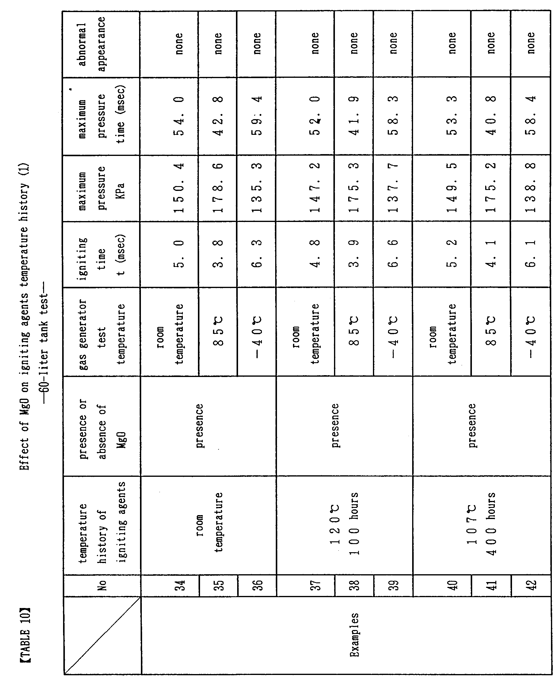

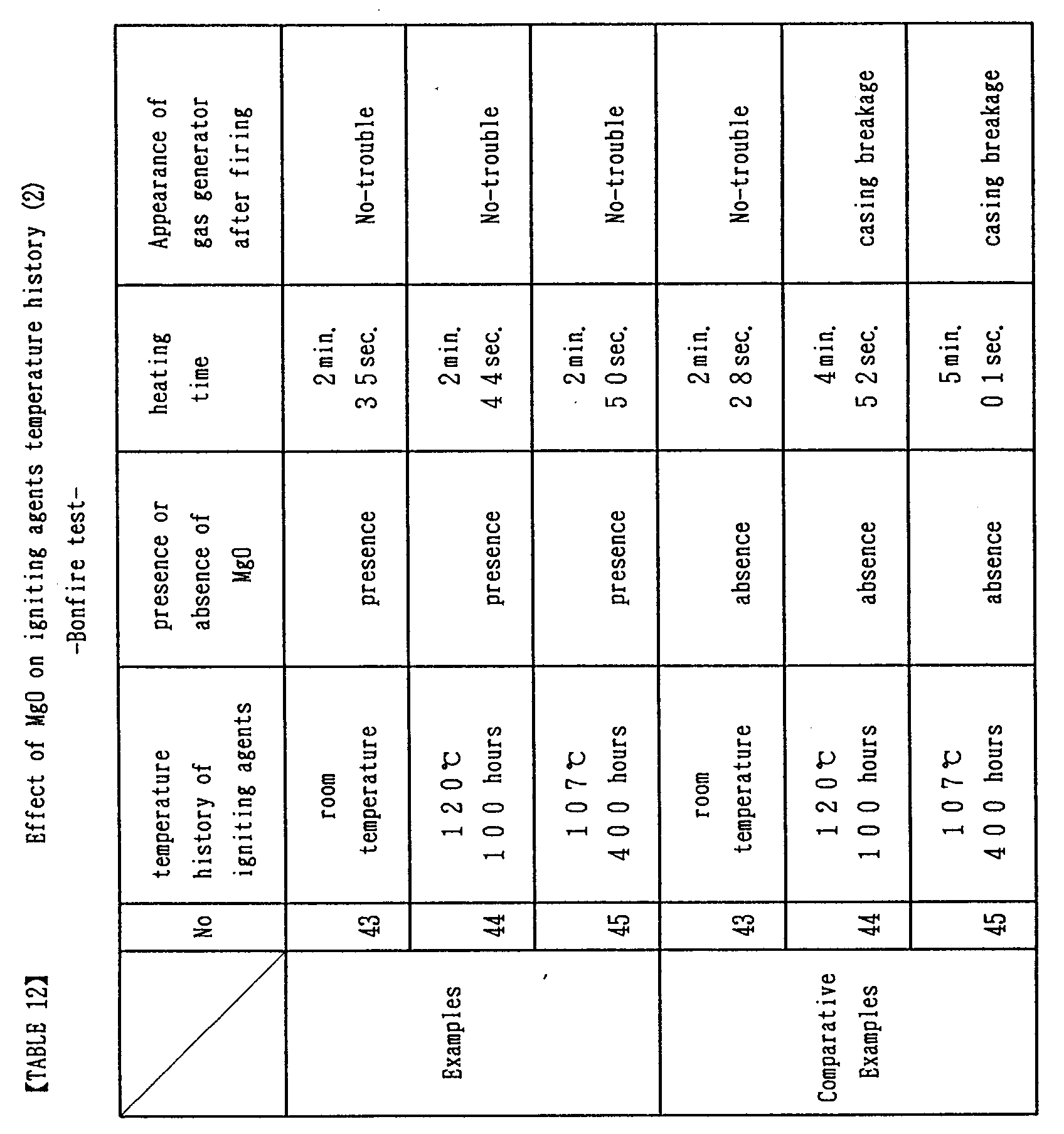
- Next, described in conjunction with Table 13 are various exemplified combinations of carbohydrates and metal oxides in a three-component spontaneous firing explosive composition of carbohydrates/oxyhalogenates/metal oxides.
- The combination given in Table 2 was mixed at the following ratio to prepare a explosive composition.
Sucrose (Taito Corporation) 23.0% by weight (Example 46, Comparative Examples 46 and 47)
Dextrin (reagent;Kishida Chemical Industries Co., Ltd.) 23.0% by weight (Example 47, Comparative Examples 48 and 49)
Cellulose (reagent; Wako Pure Chemical Industries Co., Ltd.) 23.0% by weight (Example 48, Comparative Examples 50 and 51)
Potassium Chlorate (reagent; Kanto Chemical Co., Ltd.) 74.0% by weight (Examples 46 through 48) and 77.0% by weight (Comparative Examples 46 through 51)
MgO (reagent; Wako Pure Chemical Industries Co., Ltd.) 2.0% by weight (Example 46)
ZnO (reagent; Wako Pure Chemical Industries Co., Ltd.) 2.0% by weight (Example 47)
CaO (reagent; Wako Pure Chemical Industries Co., Ltd.) 2.0% by weight (Example 48)
The mixture was made by means of two steps mixing, wherein at first, carbohydrates and potassium chlorate were respectively mixed up with metal oxides, and then these mixtures were mixed together. - The resultant spontaneous firing explosive compositions were subjected to measurements on the pressure maximum time and the generated pressure by using a test vessel obtained by attaching a pressure sensor to a stain less vessel having an inner volume of 1 liter, in which the spontaneous firing explosive composition 15 gram was burned in the form of powder (1-liter tank test).
- To ignite the spontaneous firing explosive composition, an ignitor having firing agents 0.6 gram contained of a boron/potassium nitrate and lead styphnate fuse heads were used. The pressure maximum time means a time interval from time when electrical current has finished flowing through the ignitor to time of raising the pressure till maximum.
- The spontaneous firing explosive compositions were applied with temperature histories of 120°C × 100 hours and 107 °C × 400 hours to determine the heat aging properties. A spontaneous firing temperature of the spontaneous firing explosive composition was measured by using a differential scanning calorimetry (Type DSC 220: Seiko Instruments Inc.). The results of the above test are summarized in Table 13.

- In Examples 46 through 48, there was no significant difference in properties between the initial properties and those after heat aging at 120 °C for 100 hours because the conditions met the specifications according to the present invention.
- In Comparative Examples 46 through 51, non-igniting were found in all after the heat aging at 120 °C for 100 hours because there were no metal oxides contained. In addition, the spontaneous firing temperature couldn't be measured. For the state after heat aging, no changes were found in Examples while their color of test vessel change into black-brown due to effect of heat in all Comparative Examples .
- As apparent from the above, the spontaneous firing explosive composition according to the present invention has a spontaneous firing function in a specific high-temperature range and kept a stable burning capability after the heat aging at 120 °C for 100 hours.
- Next, described are examples where a four-component spontaneous firing explosive composition according to the present invention (carbohydrates/oxyhalogenates/metal oxides/synthetic resins) is contained in the squib. This squib was assessed solely, too.
- In Fig, 11, a
pressure sensor 110 was attached to aSUS container 100 with aspace 101 of a capacity of 10 milli-liters. Thesquib 10 was attached to a lid of theSUS container 100. The electrode lead pins 7 of thesquib 10 were connected to a squib ignition power source and an oscillograph for current measurement.
A terminal of thepressure sensor 110 was connected to the measurement oscillograph. A predetermined electrical current was flown across the squib to initiate it. An initiating time t (msec.) and maximum pressure value Pmax. (psi.) were measured. An initiating time t (msec.) means a time up to start raising the pressure after an electrical current has finished flowing through the squib. - A spontaneous firing explosive composition was prepared as follows. 1.2 parts of said super fine powder of light magnesium oxide (reagent; Wako Pure Chemical Industries Co., Ltd.) was added to and mixed with 74.8 parts of potassium chlorate (reagent; Wako Pure Chemical Industries Co., Ltd.) having an average particle diameter of 0.2 mm, After mixing, it was found that the surfaces of the potassium chlorate was coated with the magnesium oxide when observed through an optical microscope. Next, 1.0 parts of said light magnesium oxide (reagent; Wako Pure Chemical Industries Co., Ltd.) was added to and mixed with 23.0 parts of sucrose (Taito Corporation) having an average particle diameter of 0.05 mm. After mixing, it was found that the surfaces of the sucrose was coated with the magnesium oxide when observed through an optical microscope. The above mentioned total amount of potassium chlorate/magnesium oxide and sucrose/magnesium oxide were mixed with each other, to which 5.0 parts of silicon resin (Shin-etsu Silicon KE 441T; Shin-etsu Chemical Co., Ltd.) was added. The mixture was kneaded over 30 minutes. Thereafter, the mixture was stood at a room temperature over 48 hours to cure the silicon resin, thereby to obtain the spontaneous firing explosive composition.
- The squib was assembled in a following manner. A
squib sheath 9 was placed in thesquib cup 6, in which the spontaneous firingexplosive composition 60 milli-gram was added. Subsequently, the initiating agents 4 (zirconium/potassium perchlorate) 140 milli-gram was placed and asquib sealing plug 1 was engaged therewith. For comparison, an explosive made of sucrose/potassium chlorate/magnesium oxide with no synthetic resins, In addition, the squib was assembled in the same manner as those described above. Histories of the squib temperature were following three types: the room temperature only, 120°C × 100 hours and 107 °C × 400 hours, The results are given in Table 14. there were significant straggling on comparative examples of both 120 °C × 100 hours and 107 °C × 400 hours, On the contrary, those according to the present invention provided stable results in the initiating time as well as the generated pressure. - In Fig. 12, the
squib 10 was attached to a lid of aSUS container 120 having aspace 101 of which a capacity is 10 milli-liters. A hole for temperature measurement was formed in the lid, in which a thermocouple was inserted to monitor a temperature in the container. Thecontainer 120 was heated with a Bunsen burner. The container temperature at which the spontaneous firing explosive composition in the squib was spontaneously fired was recorded. The squib was as same as that used in the above mentioned examples. The results are given in Table 15. On comparative examples, the spontaneous firing explosive composition in the squib were spontaneously fired at 200 °C or higher, and of which struggling were significant. On the contrary, those according to the present invention were all spontaneously fired at and around 180 °C after the above mentioned heat aging test with less straggling. - In the gas generator 61 for air bag in Fig. 2 where the
squib 10 was exposed to within the casing, the same squib as the one described in said examples was attached to a gas generator of an aluminum casing where the amount of agents in thegas generant pellets 51 and the ignitingagent 41 were 55 gram and 1.7 gram, respectively. The gas generator was suspended in the air and subjected to a bonfire test with being heated by flame generated by firewood to be spontaneously fired. A heating time until spontaneous firing and a state of the gas generator after firing were observed. The results are given in Table 16. On comparative examples, the heat aging tests of 120°C × 100 hours and 107 °C × 400 hours both resulted in filter breakage. On the contrary, those according to the present invention were not changed in appearance.


- Next, described are examples where a four-component spontaneous firing explosive composition according to the present invention (carbohydrates/oxyhalogenates/metal oxides /a synthetic resins) is contained in gas generant.
- A spontaneous firing explosive composition was prepared as follows. 1.2 parts of said super fine powder of light magnesium oxide (reagent; Wako Pure Chemical Industries Co., Ltd.) was added to and mixed with 74.8 parts of potassium chlorate (reagent; Wako Pure Chemical Industries Co., Ltd.) having an average particle diameter of 0.2 mm. After mixing, it was found that the surfaces of the potassium chlorate was coated with the magnesium oxide when observed through an optical microscope. Next, 1.0 parts of said light magnesium oxide (reagent; Wako Pure Chemical Industries Co., Ltd.) was added to and mixed with 23.0 parts of sucrose (Taito Corporation) having an average particle diameter of 0.05 mm. After mixing, it was found that the surface of the sucrose was coated with the magnesium oxide when observed through an optical microscope. The above mentioned total amount of potassium chlorate/magnesium oxide and sucrose/magnesium oxide were mixed with each other, to which 5.0 parts of silicon resin (Shin-etsu Silicon KE 441T; Shin-etsu Chemical Co., Ltd.) was added. The mixture was kneaded over 30 minutes. Thereafter, the mixture was stood at a room temperature over 48 hours to cure the silicon resin, thereby to obtain the spontaneous firing explosive composition.
- This spontaneous firing explosive composition was placed in a mill of which diameter is 10 mm and press-molded under a load of 500 kilo-gram to obtain pellets of the gas generant, Weight of one pellet is approximately 0.6 gram. As shown in Fig. 7, the above mentioned
pellets 35 gram were placed in thegas generant container 50 and sealed as shown in Fig. 6. Twelve containers such as the above mentionedgenerant containers 50 were ready. We applied three types of temperature histories. Here are: room temperature, 120°C × 100 hours and 107 °C × 400 hours, We used four containers to each types. Thereafter, as shown in Fig, 1, thegas generator 60 made of the aluminum casing was assembled. Thegas generator 60 contains thesquib 10 having zirconium/potassium perchlorate 120 milli-gram, the ignitingagent container 40 having the igniting agent (boron/potassium nitrate) 1.0 gram and the above mentionedgas generant container 50. Thisgas generator 60 was used for test of a pressure-time with a 60-liter tank and a heating test with firewood (bonfire test). The results are given in Table 17 and Table 19. Differences in temperature histories during the 60-liter tank pressure-time test were slight. During the bonfire test, there were no differences in temperature histories found. An igniting time t (msec.) means a time up to start raising the pressure after an electrical current has finished flowing through the squib. Maximum pressure time means a time for pressure to become maximum. A heating time t in Table 12 means a time for thegas generator 60 to fire. -
- For comparison with the above mentioned examples, a gas generant was prepared without granulating with a silicon resin. As in the above, this was placed in a mill of which diameter is 10 mm and press-molded under a load of 500 kilo-gram to obtain pellets of the gas generant. Weight of one pellet is approximately 0.6 gram. As shown in Fig. 7, the above mentioned
pellets 35 gram were placed in thegas generant container 50 and sealed as shown in Fig. 6. Twelve containers such as the above mentionedgenerant containers 50 were ready. We applied three types of temperature histories. Here are: room temperature, 120°C × 100 hours and 107 °C × 400 hours. We used four containers to each types. Thereafter, as shown in Fig, 1, thegas generator 60 made of the aluminum casing was assembled. Thegas generator 60 contains thesquib 10 having zirconium/potassium perchlorate 120 milli-gram, the ignitingagents container 40 having the igniting agents(boron/potassium nitrate) 1.0 gram and the above mentionedgas generant container 50. Thisgas generator 60 was used for test of a pressure-time with a 60-liter tank and a heating test with firewood (bonfire test). The results are given in Table 18 and Table 19. During the 60-liter tank pressure-time test, there were a significant struggling in results. During the bonfire test, filter breakage was caused.


- A spontaneous firing explosive composition was prepared as follows. 23.0 parts of wood powder having an average particle diameter of 0.05 mm was added to and mixed with 1.0 parts of said light magnesium oxide (reagent; Wako Pure Chemical Industries Co., Ltd.), to which 76.6 parts of potassium chlorate/magnesium oxide mixture prepared in said examples was added and mixed with each other, to which 5.0 parts of silicon resin was added. The mixture was kneaded over 30 minutes. Thereafter, the mixture was stood at a room temperature over 48 hours to cure the silicon resin, 24.0 parts of the above mentioned wood powder/potassium chlorate/magnesium oxide/silicon resin composition was mixed with 76.0 parts of spontaneous firing explosive composition based on sucrose/potassium chlorate/magnesium oxide/silicon resin prepared in said examples to obtain gas generant powder. As shown in Fig. 8, the above mentioned
gas generant 35 gram was placed in thegas generant container 50 and sealed as shown in Fig. 6. Twelve containers such as the above mentionedgenerant containers 50 were ready. We applied three types of temperature histories. Here are: room temperature, 120 °C × 100 hours and 107 °C × 400 hours, We used four containers to each types. Thereafter, as shown in Fig. 1, thegas generator 60 made of the aluminum casing was assembled. Thegas generator 60 contains thesquib 10 having zirconium/potassium perchlorate 120 milli-gram, the ignitingagents container 40 having the igniting agents(boron/potassium nitrate) 1.0 gram and the above mentionedgas generant container 50. Thisgas generator 60 was used for test of a pressure-time with a 60-liter tank and a heating test with firewood (bonfire test). The results are given in Table 20 and Table 22. Differences in temperature histories during the 60-liter tank pressure-time test were slight. During the bonfire test, there were no differences in temperature histories found. - A wood powder/sucrose/potassium chlorate/magnesium oxide mixture was prepared as a gas generant in the same manner and same ratio of the above mentioned examples 22 to 30 without silicon resin. As shown in Fig, 8, the above mentioned
gas generant 35 gram was placed in thegas generant container 50 and sealed as shown in Fig. 6. Twelve containers such as the above mentionedgenerant containers 50 were ready. We applied three types of temperature histories. Here are: room temperature, 120°C × 100 hours and 107 °C × 400 hours. We used four containers to each types. Thereafter, as shown in Fig. 1, thegas generator 60 made of the aluminum casing was assembled. Thegas generator 60 contains thesquib 10 having zirconium/potassium perchlorate 120 milli-gram, the ignitingagents container 40 having the igniting agents(boron/potassium nitrate) 1.0 gram and the above mentionedgas generant container 50. Thisgas generator 60 was used for test of a pressure-time with a 60-liter tank and a heating test with firewood (bonfire test). The results are given in Table 21 and Table 22. During the 60-liter tank pressure-time test, there were a significant struggling in results. During the bonfire test, filter breakage was caused.


- Next, described are examples where a spontaneous firing explosive composition according to the present invention (carbohydrates/oxyhalogenates/metal oxides/synthetic resins) was contained in the igniting agents.
- A spontaneous firing explosive composition was prepared as follows. 1.2 parts of said light magnesium oxide (reagent; Wako Pure Chemical Industries Co., Ltd.) was added to and mixed with 74.8 parts of potassium chlorate (reagent; Wako Pure Chemical Industries Co., Ltd.) having an average particle diameter of 0.2 mm. After mixing, it was found that the surfaces of the potassium chlorate were coated with the magnesium oxide when observed through an optical microscope, Next, 1.0 parts of said light magnesium oxide (reagent; Wako Pure Chemical Industries Co., Ltd.) were added to and mixed with 23.0 parts of sucrose (Taito Corporation) having an average particle diameter of 0.05 mm. After mixing, it was found that the surfaces of the sucrose were coated with the magnesium oxide when observed through an optical microscope. The above mentioned total amount of potassium chlorate/magnesium oxide and sucrose/magnesium oxide were mixed with each other, to which 5.0 parts of silicon resin (Shin-etsu Silicon KE 441T; Shin-etsu Chemical Co., Ltd.) were added. The mixture was kneaded over 30 minutes, Thereafter, the mixture was stood at a room temperature over 48 hours to cure the silicon resin, thereby to obtain the spontaneous firing explosive composition.
- As shown in Fig. 9, the above mentioned spontaneous firing explosive composition 2.0 gram was placed in the igniting
agents container 40 and sealed. Twelve containers such as the above mentioned ignitingagents containers 40 were ready. We applied three types of temperature histories. Here are: room temperature, 120°C × 100 hours and 107 °C × 400 hours. We used four containers to said each types. Thereafter, as shown in Fig. 1, thegas generator 60 made of the aluminum casing was assembled. Thegas generator 60 contains thesquib 10 having zirconium/potassium perchlorate 120 milli-gram, thegas generant container 50 having the gas generant based on sodium azide 55 gram, and the ignitingagents container 40 having the above mentioned spontaneous firing explosive composition. Thisgas generator 60 was used for test of a pressure-time with a 60-liter tank and a heating test with firewood (bonfire test). The results are given in Table 23 and Table 25. Differences in temperature histories during the 60-liter tank pressure-time test were slight. During the bonfire test, there were no differences in temperature histories found. An igniting time t (msec.) means a time up to start raising the pressure after an electrical current has finished flowing through the squib. Maximum pressure time means a time for pressure to become maximum. A heating time t means a time for thegas generator 60 to fire. - For comparison with said examples, a sucrose /potassium chlorate/magnesium oxide was prepared as igniting agents without synthetic resins. This igniting agents were placed in the igniting agents container in the same manner of said examples, Twelve containers such as the above mentioned igniting
agents containers 40 were ready. We applied three types of temperature histories, Here are: room temperature, 120°C × 100 hours and 107 °C × 400 hours. We used four containers to said each types. Thereafter, as shown in Fig. 1, the gas generator was assembled with the same specifications of said examples except for the igniting agents. This gas generator is used to conduct the same assessment tests as in said examples. The results are given in Table 24 and Table 25. During the 60-liter tank pressure-time test, there was a significant struggling in results. During the bonfire test, filter breakage was caused.


- Next, described in conjunction with Table 26 are various exemplified combinations of carbohydrates, metal oxides and synthetic resins in a spontaneous firing explosive composition of carbohydrates/oxyhalogenates/metal oxides/synthetic resins,
- The combination given in Table 26 was mixed at the following ratio to prepare an explosive composition.
- Sucrose (Taito Corporation) 23.0% by weight (Example 46 and 47, Comparative Examples 46 and 49)
Dextrin (reagent;Kishida Chemical Industries Co., Ltd.) 23.0% by weight (Examples 48 and 49, Comparative Examples 47 and 50)
Cellulose (reagent; Wako Pure Chemical Industries Co., Ltd.) 23.0% by weight (Examples 50 and 51, Comparative Examples 48 and 51)
Potassium Chlorate (reagent; Kanto Chemical Co., Ltd.) 74.0% by weight (Examples 46 through 51) and 77.0% by weight (Comparative Examples 46 through 51)
MgO (reagent; Wako Pure Chemical Industries Co., Ltd.) 2.0% by weight (Examples 46 through 48 and 50, Comparative Example 46)
ZnO (reagent; Wako Pure Chemical Industries Co., Ltd.) 2.0% by weight (Example 49, Comparative Example 47)
CaO (reagent; Wako Pure Chemical Industries Co., Ltd.) 2.0% by weight (Example 51, Comparative Example 48)
Silicon Resin (One-component room-temperature curable type) (Trade Name "Shin-etsu Silicon KE 441T" available from Shin-etsu Chemical Co., Ltd.) (Examples 46, 48 and 50, Comparative Examples 49 through 51)
Urethane Resin (Trade Name "Hi-Bon 4601" available from Hitachi Kasei Polymer Co., Ltd.) (Example 47)
Butyl Rubber (Trade Name "Hi-Bon 1010A" available from Hitach Kasei Polymer Co., Ltd.) (Example 49)
Polyester Resin (Trade Name "Hi-Bon 7031L" available from Hitachi Kasei Polymer Co., Ltd.) (Example 51). - The mixture was made by means of two steps mixing. At first, carbohydrates and potassium chlorate are respectively mixed up with metal oxides and then these mixtures are mixed together. Thereafter, the synthetic resins were added thereto, which was kneaded and granulated over 30 minutes and was stood at a room temperature over 48 hours for curing the resins.
- The resultant spontaneous firing explosive compositions were subjected to measurements on the generated pressure and the time when said generated pressure rises up till maximum by using a test vessel obtained by attaching a pressure sensor to a stainless vessel having an inner volume of 1 liter, in which the spontaneous firing
explosive composition 8 gram was burned in the form of granule (1-liter tank test). - To ignite the spontaneous firing explosive composition, a squib having firing agent 0.6 gram contained of a boron/potassium nitrate and lead styphnate fuse heads were used. The igniting time means a time interval from time when electrical current has finished flowing through the squib to time of starting raising the pressure.
- The spontaneous firing explosive compositions were applied with temperature history of 120°C × 100 hours to determine the heat aging properties. A spontaneous firing temperature of the spontaneous firing explosive compositions was measured by using a differential thermal analyzer (Type DSC 220: Seiko Instruments Inc.). The results of the above tests are summarized in Table 26.

- In Examples 46 through 51, there were no significant differences in properties between the initial properties and those after heat aging at 120 °C for 100 hours because the conditions met the specifications according to the present invention. In particular, reproducibility of the spontaneous firing temperature was excellent.
- In Comparative Examples 46 through 48, the spontaneous firing temperatures were increased because there were no synthetic resins contained. The spontaneous firing temperatures were further increased after the heat aging at 120 °C for 100 hours. In Comparative Examples 49 through 51, non-igniting were found after the heat aging at 120 °C for 100 hours because there were no metal oxides contained. In addition, the spontaneous firing temperature couldn't be measured. For the state after heat aging, no changes were found in Examples and Comparative Examples 46 through 48 while Comparative Examples 49 through 51 resulted in color change into black-brown due to effect of heat.
- As apparent from the above, the spontaneous firing explosive composition according to the present invention has a spontaneous firing function in a specific high-temperature range and kept a stable burning capability after the heat aging at 120 °C for 100 hours.
- As described in detail above, the gas generator for air bag according to the present invention requires no preparation of a specific container space in a casing by means of containing a spontaneous firing explosive composition comprising carbohydrates, oxyhalogenates and metal oxides in at least one of the squib, the igniting agents and the gas generant, and it is thus possible to maintain stable properties for a long time with safety and a spontaneous firing function at a low temperature up to 220 °C without particular considerations on the heat conductivity between the casing, so that it is optimum as the gas generator with the casing of a light alloy material or the like of which mechanical strength will be deteriorated when being subjected to high temperature environments. When the heat conductivity from outside is not so good, it is possible to further ensure the spontaneous firing function at a low temperature up to 200°C by means of containing a spontaneous firing explosive composition consisting of carbohydrates, oxyhalogenates, metal oxides and synthetic resins.
- In particular, when the squib contains the spontaneous firing explosive composition according to the present invention as compared with a case where it is contained in the gas generant or the firing agents, this eliminates a fear of the explosive left in the casing without igniting of the squib after the spontaneous firing of said explosive composition. In addition, in case of prior art such as a spontaneous firing explosive composition also serving as initiating agents, the bridge wire contacting therewith is corroded due to acidic substances generated as a result of deterioration with time. So, there's a fear for an incorrect operation because of the squib not initiated upon a normal operation. While in case of the present invention, there's no fear such as said trouble. Further, the present invention can find various applications as the squib having the spontaneous firing function.
- In particular, when the gas generant contains the spontaneous firing explosive composition according to the present invention, no toxic gas is generated after it absorbs water as compared with conventional ones based on sodium azide. It can be a gas generator containing a novel gas generant which is capable of maintaining stable properties during exposure to high temperature environments for a long time and which has an adequate burning rate in a normal operation.
- Further, when the igniting agents contains the spontaneous firing explosive composition according to the present invention, this is possible to obtain a more excellent high-temperature stability and a more sufficient burning rate than ones of the prior art such as a spontaneous firing explosive composition also serving as igniting agents.
- The present invention is a gas generator for air bag comprises a spontaneous firing explosive composition in which at least one of a
squib 10, ignitingagents 41 and agas generant 51 contained in acasing
Claims (27)
- A gas generator for air bag comprising a squib or one or more igniting agents and a gas generant contained therein, wherein at least one of said squib, said igniting agents and said gas generant contains a spontaneous firing explosive composition comprising carbohydrates, oxyhalogenates and metal oxides.
- A gas generator for air bag as claimed in Claim 1, wherein said squib, said igniting agents, or said gas generator is contained in a casing made of a light alloy material such as an aluminum alloy, wherein said spontaneous firing explosive composition being spontaneously fired at temperatures from 165°C to 220 °C.
- A gas generator for air bag as claimed in Claim 1 containing said spontaneous firing explosive composition wherein said carbohydrates of which an average particle diameter from 0.5 mm to 0.0001 mm, said oxyhalogenates of which an average particle diameter from 1.0 mm to 0.0001 mm, said metal oxides of which an average particle diameter from 0.5 mm or smaller.
- A gas generator for air bag as claimed in Claim 1, wherein said carbohydrates, said oxyhalogenates and said metal oxides in said spontaneous firing explosive composition are respectively from 95.0% to 1.0% by weight, from 95.0% to 1.0% by weight and from 30.0% to 0.01% by weight.
- A gas generator for air bag as claimed in Claim 1, wherein at least one of said carbohydrates and said oxyhalogenates in said spontaneous firing explosive composition is coated with said metal oxides.
- A gas generator for air bag as claimed in Claim 1, wherein said carbohydrates, said oxyhalogenates and said metal oxides in said spontaneous firing explosive composition were mixed uniformly.
- A gas generator for air bag as claimed in Claim 1 containing said spontaneous firing explosive composition, wherein said carbohydrates is sucrose, wherein said oxyhalogenates is a single or a mixture of chlorate, perchlorate, bromate, perbromate, iodate and periodate and where in said metal oxides is a single or a mixture of calcium oxide, magnesium oxide and zinc oxide.
- A gas generator for air bag comprising a squib or one or more igniting agents and a gas generant contained therein, wherein at least one of said squib, said igniting agents and said gas generant contains a spontaneous firing explosive composition comprising carbohydrates, oxyhalogenates, metal oxides and a synthetic resins.
- A gas generator for air bag as claimed in Claim 8, wherein said squib, said igniting agents, or said gas generator is contained in a casing made of a light alloy material such as an aluminum alloy, wherein said spontaneous firing explosive composition being spontaneously fired at a temperatures from 165°C to 200 °C.
- A gas generator for air bag as claimed in Claim 8 containing said spontaneous firing explosive composition wherein the carbohydrates of which an average particle diameter of from 0.5 mm to 0.0001 mm, said oxyhalogenates of which an average particle diameter of from 1.0 mm to 0.0001 mm, said metal oxides of which an average particle diameter of from 0.5 mm or smaller.
- A gas generator for air bag as claimed in Claim 8, wherein said carbohydrates, said oxyhalogenates, said metal oxides and said synthetic resins in said spontaneous firing explosive composition are respectively from 95.0% to 1.0% by weight, from 95.0% to 1.0% by weight, from 30.0% to 0.01% by weight and from 0.5% to 20.0% by weight.
- A gas generator for air bag as claimed in Claim 8, wherein at least one of said carbohydrates and said oxyhalogenates in said spontaneous firing explosive composition are coated with said metal oxides.
- A gas generator for air bag as claimed in Claim 8, wherein said carbohydrates, the said oxyhalogenates and said metal oxides in said spontaneous firing explosive composition were mixed uniformly.
- A gas generator for air bag as claimed in Claim 8, wherein a mixture of said carbohydrates, said oxyhalogenates and said metal oxides is granulated by said synthetic resins.
- A gas generator for air bag as claimed in Claim 8 containing said spontaneous firing explosive composition, wherein said carbohydrates is sucrose, where in said oxyhalogenates is a single or a mixture of chlorate, perchlorate, bromate, perbromate, iodate and periodate, wherein said metal oxides is a single or a mixture of calcium oxide, magnesium oxide and zinc oxide and wherein said synthetic resins is any one of silicon resins, urethane resins, polyesters, acrylic resins and butyl rubbers.
- A squib comprising a magazine which is formed with a squib cup and a squib plug and is sealed; a pair of electrode lead pins penetrating through said squib plug to said magazine; a bridge wire connected to ends of said electrode lead pins ; and a explosive contained in said magazine; said explosive containing a spontaneous firing explosive composition comprising carbohydrates, oxyhalogenates and metal oxides.
- A squib as claimed in Claim 16, wherein said explosive is in a layer structure consisting of initiating agents contacting with the bridge wire and the spontaneous firing explosive composition contacting with said initiating agents.
- A squib comprising a magazine which is formed with a squib cup and a squib plug and is sealed; an electrode lead pins penetrating through said squib plug to said magazine; a bridge wire connected to ends of said electrode lead pins; and an explosive contained in said magazine; said explosive containing a spontaneous firing explosive composition comprising carbohydrates, oxyhalogenates, metal oxides and a synthetic resin.
- A squib as claimed in Claim 18, wherein said explosive is in a layer structure consisting of initiating agents contacting with the bridge wire and the spontaneous firing explosive composition contacting with said initiating agents.
- A gas generator for air bag in which a squib is held by a casing made of a light metal material such as an aluminum alloy;
said squib comprising a magazine which is formed with a squib cup and a squib plug and is sealed, a pair of electrode pins penetrating through said squib plug to said magazine, a bridge wire connected to ends of said electrode lead pins and an explosive contained in said magazine,
said explosive being in a layer structure consisting of initiating agents contacting with said bridge wire and said spontaneous firing explosive composition contacting with said initiating agents ; said spontaneous firing explosive composition comprising carbohydrates, oxyhalogenates, metal oxides and a synthetic resins, a portion of said squib corresponding to the spontaneous firing explosive composition being exposed within said casing without contact to said casing. - A gas generator for air bag comprising a casing formed of a light metal material such as aluminum alloy with an upper casing member and a lower casing member having an inner cylinder and an outer cylinder respectively, which are opposed to and frictional welded with each other corresponding to said inner cylinders and outer cylinders each other and having a center space within said inner cylinder and an outer space surrounded by said inner cylinder and said outer cylinder; igniting agents and a squib being arranged within said center space and a gas generant and a filter being arranged within said outer space,
an outer surface of said squib being coated with an electrically insulating material, said coated squib being inserted into said casing and fixed thereto and containing the spontaneous firing explosive composition consisting of carbohydrates, oxyhalogenates, metal oxides and a synthetic resin. - A gas generator for air bag as claimed in Claim 21, wherein said squib is inserted into a cylinder-shaped boss projected from outside of said casing into said center space and fixed thereto, said cylinder-shaped boss being larger in height than the portion of said friction welding.
- A spontaneous firing explosive composition comprising carbohydrates, oxyhalogenates and metal oxides.
- A spontaneous firing explosive composition as claimed in Claim 23, wherein said spontaneous firing explosive composition being spontaneously fired at temperatures from 165°C to 220 °C.
- A spontaneous firing explosive composition as claimed in Claim 23, wherein said carbohydrates is sucrose, wherein said oxyhalogenates is a single or a mixture of chlorate, perchlorate, bromate, perbromate, iodate and periodate and wherein said metal oxides is a single or a mixture of calcium oxide, magnesium oxide and zinc oxide.
- A spontaneous firing explosive composition comprising carbohydrates, oxyhalogenates, metal oxides and a synthetic resin.
- A spontaneous firing explosive composition as claimed in Claim 26, wherein said carbohydrates is sucrose, wherein said oxyhalogenates is a single or a mixture of chlorate, perchlorate, bromate, perbromate, iodate and periodate, where in said metal oxides is a single or a mixture of calcium oxide, magnesium oxide and zinc oxide and wherein said synthetic resin is any one of silicon resins, urethane resins, polyesters, acrylic resins and butyl rubbers.
Applications Claiming Priority (4)
| Application Number | Priority Date | Filing Date | Title |
|---|---|---|---|
| JP353718/93 | 1993-12-28 | ||
| JP35371893 | 1993-12-28 | ||
| JP180570/94 | 1994-07-07 | ||
| JP6180570A JPH07232613A (en) | 1993-12-28 | 1994-07-07 | Gas generator for air bag and squib |
Publications (2)
| Publication Number | Publication Date |
|---|---|
| EP0665138A2 true EP0665138A2 (en) | 1995-08-02 |
| EP0665138A3 EP0665138A3 (en) | 1997-05-07 |
Family
ID=26500049
Family Applications (1)
| Application Number | Title | Priority Date | Filing Date |
|---|---|---|---|
| EP94120732A Withdrawn EP0665138A3 (en) | 1993-12-28 | 1994-12-27 | Gas generator, squib for air bag and spontaneous firing explosive composition. |
Country Status (7)
| Country | Link |
|---|---|
| US (1) | US5756928A (en) |
| EP (1) | EP0665138A3 (en) |
| JP (1) | JPH07232613A (en) |
| KR (1) | KR0139488B1 (en) |
| AU (1) | AU683313B2 (en) |
| CA (1) | CA2139042A1 (en) |
| TW (1) | TW263474B (en) |
Cited By (18)
| Publication number | Priority date | Publication date | Assignee | Title |
|---|---|---|---|---|
| GB2298476A (en) * | 1994-04-26 | 1996-09-04 | Breed Automotive Tech | Inflator assembly for an air bag |
| WO1997008018A2 (en) * | 1995-08-29 | 1997-03-06 | Trw Airbag Systems Gmbh & Co. Kg. | Early detonation device |
| WO1998003448A1 (en) * | 1996-07-20 | 1998-01-29 | Dynamit Nobel Gmbh Explosivstoff- Und Systemtechnik | Temperature fuse |
| EP0934853A1 (en) * | 1996-10-29 | 1999-08-11 | Daicel Chemical Industries, Ltd. | Gas producer for air bag |
| EP0938422A1 (en) * | 1996-10-30 | 1999-09-01 | Atlantic Research Corporation | Autoignition propellant containing superfine iron oxide and method of lowering the autoignition temperature of an igniter |
| EP0959057A1 (en) * | 1996-10-22 | 1999-11-24 | Chugai Seiyaku Kabushiki Kaisha | Coated oxidizing agent |
| WO2000021907A1 (en) * | 1998-10-14 | 2000-04-20 | Cordant Technologies, Inc. | Foamed energetic igniters and air bag assemblies containing the same |
| WO2000064840A1 (en) * | 1999-04-27 | 2000-11-02 | Dynamit Nobel Gmbh Explosivstoff- Und Systemtechnik | Granulated gas charges |
| US6364354B1 (en) | 1998-09-28 | 2002-04-02 | Daicel Chemical Industries, Ltd. | Air bag gas generator and air bag apparatus |
| US6453816B2 (en) | 1996-07-20 | 2002-09-24 | Dynamit Nobel Gmbh Explosivstoff-Und Systemtechnik | Temperature fuse with lower detonation point |
| US6460884B1 (en) | 1998-09-28 | 2002-10-08 | Daicel Chemical Industries, Ltd. | Air bag gas generator and air bag apparatus |
| US6491321B1 (en) | 1999-02-16 | 2002-12-10 | Daicel Chemical Industries, Ltd. | Multistage gas generator for air bag and air bag apparatus |
| US6547275B2 (en) | 1998-11-30 | 2003-04-15 | Daicel Chemical Industries, Ltd. | Air bag gas generator and air bag device |
| EP1343658A2 (en) * | 2000-11-28 | 2003-09-17 | Automotive Systems Laboratory Inc. | Gas generator and method of assembly |
| EP1346886A1 (en) * | 2000-12-27 | 2003-09-24 | Daicel Chemical Industries, Ltd. | Air bag-use gas generator and air bag device |
| WO2005058775A1 (en) * | 2003-12-17 | 2005-06-30 | Ruag Ammotec Gmbh | Thermal pre-ignition agents |
| FR2870234A1 (en) * | 2004-05-13 | 2005-11-18 | Snpe Materiaux Energetiques Sa | DOSABLE PYROTECHNIC COMPOSITION USED AS A THERMAL FUSE IN A GAS GENERATOR AND A GAS GENERATOR INCLUDING A COMPOUND HAVING THE SAME |
| DE19929279B4 (en) * | 1998-06-26 | 2016-12-01 | Daicel Chemical Industries, Ltd. | Gas generator for airbag and airbag system |
Families Citing this family (18)
| Publication number | Priority date | Publication date | Assignee | Title |
|---|---|---|---|---|
| US5847310A (en) * | 1993-12-28 | 1998-12-08 | Nippon Kayaku Kabushiki-Kaisha | Squib for an air bag with an auto ignition composition |
| FR2782078B1 (en) * | 1998-08-10 | 2000-11-03 | Lacroix Soc E | SMOKE COMPOSITION BASED ON COLOPHANE DERIVATIVES |
| US6492588B1 (en) | 1998-08-26 | 2002-12-10 | Prestolite Wire Corporation | Self suppression wire or cable, and ferrite bead in combination |
| US6362418B1 (en) | 1999-08-25 | 2002-03-26 | Prestolite Wire Corporation | Self suppression wire for airbag ignitors and self suppression wire cable |
| CN100335317C (en) * | 1999-02-16 | 2007-09-05 | 大赛璐化学工业株式会社 | Multistage air bag apparatus, connector and multistage gas generator for air bag |
| TW469235B (en) * | 1999-10-04 | 2001-12-21 | Daicel Chem | Gas generator for air bag and air bag device |
| EP1266807B1 (en) | 2000-03-13 | 2006-04-26 | Nippon Kayaku Kabushiki Kaisha | Gas generator |
| KR100442551B1 (en) * | 2001-10-23 | 2004-07-30 | 김창선 | Contact-detonating device of rapidly explosive compound material |
| EP1487676A2 (en) * | 2002-03-26 | 2004-12-22 | Automotive Systems Laboratory, Inc. | Multiple chamber dual stage inflator |
| AU2003264358A1 (en) * | 2002-08-30 | 2004-04-30 | Nippon Kayaku Kabushiki Kaisha | Micro gas generator with automatic ignition function |
| US6939389B2 (en) * | 2003-08-08 | 2005-09-06 | Frank Mooney | Method and apparatus for manufacturing fine powders |
| US7052041B2 (en) * | 2003-08-28 | 2006-05-30 | Automotive Systems Laboratory, Inc. | Gas generator and gas generant packet used therein |
| US20060220363A1 (en) * | 2005-03-31 | 2006-10-05 | Blackburn Jeffery S | Gas generating system with autoignition device |
| PL1710871T3 (en) * | 2005-04-08 | 2008-01-31 | Auto Kabel Man Mbh | Current separator for the electrical cables in a car |
| DE102008052481B4 (en) * | 2008-10-17 | 2012-04-26 | Takata-Petri Ag | Gas generator assembly for a motor vehicle |
| DE102008055904B4 (en) * | 2008-11-05 | 2018-03-22 | Auto-Kabel Management Gmbh | Plug connection for an occupant protection device |
| DE102010011150B4 (en) * | 2010-03-11 | 2012-03-29 | Auto-Kabel Managementgesellschaft Mbh | Electrical fuse for motor vehicle power lines and method of manufacture of such fuse |
| JP6851176B2 (en) * | 2016-10-28 | 2021-03-31 | 日本化薬株式会社 | Gas generator |
Citations (4)
| Publication number | Priority date | Publication date | Assignee | Title |
|---|---|---|---|---|
| US1831760A (en) * | 1928-07-11 | 1931-11-10 | Wieben Anella | Igniting composition |
| US3862866A (en) * | 1971-08-02 | 1975-01-28 | Specialty Products Dev Corp | Gas generator composition and method |
| US4858951A (en) * | 1988-05-04 | 1989-08-22 | Trw Vehicle Safety Systems, Inc. | Igniter for gas generating material |
| DE4134859A1 (en) * | 1991-10-22 | 1993-04-29 | Allemann Gmbh Holz Und Metallp | Chromate- and manganese oxide-free ignition compsns. for safety matches - contain binder, fuel, filler, titanium di:oxide as catalyst and oxidn. agent |
Family Cites Families (12)
| Publication number | Priority date | Publication date | Assignee | Title |
|---|---|---|---|---|
| US3880595A (en) * | 1972-06-08 | 1975-04-29 | Hubert G Timmerman | Gas generating compositions and apparatus |
| FR2190776B1 (en) * | 1972-07-05 | 1976-10-29 | Poudres & Explosifs Ste Nale | |
| US3901747A (en) * | 1973-09-10 | 1975-08-26 | Allied Chem | Pyrotechnic composition with combined binder-coolant |
| US4214438A (en) * | 1978-02-03 | 1980-07-29 | Allied Chemical Corporation | Pyrotechnic composition and method of inflating an inflatable device |
| US4238253A (en) * | 1978-05-15 | 1980-12-09 | Allied Chemical Corporation | Starch as fuel in gas generating compositions |
| US4923212A (en) * | 1988-08-17 | 1990-05-08 | Talley Automotive Products, Inc. | Lightweight non-welded inflator unit for automobile airbags |
| US5046429A (en) * | 1990-04-27 | 1991-09-10 | Talley Automotive Products, Inc. | Ignition material packet assembly |
| US5089069A (en) * | 1990-06-22 | 1992-02-18 | Breed Automotive Technology, Inc. | Gas generating composition for air bags |
| US5139588A (en) * | 1990-10-23 | 1992-08-18 | Automotive Systems Laboratory, Inc. | Composition for controlling oxides of nitrogen |
| US5035757A (en) * | 1990-10-25 | 1991-07-30 | Automotive Systems Laboratory, Inc. | Azide-free gas generant composition with easily filterable combustion products |
| US5439537A (en) * | 1993-08-10 | 1995-08-08 | Thiokol Corporation | Thermite compositions for use as gas generants |
| WO1995026945A1 (en) * | 1994-04-04 | 1995-10-12 | Automotive Systems Laboratory, Inc. | Gas generator autoignition with a chlorate composition |
-
1994
- 1994-07-07 JP JP6180570A patent/JPH07232613A/en active Pending
- 1994-12-12 AU AU80388/94A patent/AU683313B2/en not_active Ceased
- 1994-12-23 CA CA002139042A patent/CA2139042A1/en not_active Abandoned
- 1994-12-27 EP EP94120732A patent/EP0665138A3/en not_active Withdrawn
- 1994-12-28 KR KR1019940038006A patent/KR0139488B1/en not_active IP Right Cessation
- 1994-12-28 US US08/365,105 patent/US5756928A/en not_active Expired - Fee Related
- 1994-12-30 TW TW083112387A patent/TW263474B/zh active
Patent Citations (4)
| Publication number | Priority date | Publication date | Assignee | Title |
|---|---|---|---|---|
| US1831760A (en) * | 1928-07-11 | 1931-11-10 | Wieben Anella | Igniting composition |
| US3862866A (en) * | 1971-08-02 | 1975-01-28 | Specialty Products Dev Corp | Gas generator composition and method |
| US4858951A (en) * | 1988-05-04 | 1989-08-22 | Trw Vehicle Safety Systems, Inc. | Igniter for gas generating material |
| DE4134859A1 (en) * | 1991-10-22 | 1993-04-29 | Allemann Gmbh Holz Und Metallp | Chromate- and manganese oxide-free ignition compsns. for safety matches - contain binder, fuel, filler, titanium di:oxide as catalyst and oxidn. agent |
Cited By (45)
| Publication number | Priority date | Publication date | Assignee | Title |
|---|---|---|---|---|
| GB2298476A (en) * | 1994-04-26 | 1996-09-04 | Breed Automotive Tech | Inflator assembly for an air bag |
| GB2298475A (en) * | 1994-04-26 | 1996-09-04 | Breed Automotive Tech | Inflator assembly for an air bag |
| GB2298476B (en) * | 1994-04-26 | 1997-08-20 | Breed Automotive Tech | Improved inflator assembly |
| GB2298475B (en) * | 1994-04-26 | 1997-08-20 | Breed Automotive Tech | Improved inflator assembly |
| WO1997008018A2 (en) * | 1995-08-29 | 1997-03-06 | Trw Airbag Systems Gmbh & Co. Kg. | Early detonation device |
| DE19531666A1 (en) * | 1995-08-29 | 1997-03-06 | Temic Bayern Chem Airbag Gmbh | Early ignition device |
| WO1997008018A3 (en) * | 1995-08-29 | 1997-03-27 | Temic Bayern Chem Airbag Gmbh | Early detonation device |
| WO1998003448A1 (en) * | 1996-07-20 | 1998-01-29 | Dynamit Nobel Gmbh Explosivstoff- Und Systemtechnik | Temperature fuse |
| US6453816B2 (en) | 1996-07-20 | 2002-09-24 | Dynamit Nobel Gmbh Explosivstoff-Und Systemtechnik | Temperature fuse with lower detonation point |
| CZ299764B6 (en) * | 1996-07-20 | 2008-11-19 | Delphi Technologies, Inc. | Thermal fuse |
| US6302978B1 (en) | 1996-10-22 | 2001-10-16 | Chugai Seiyaku Kabushiki Kaisha | Coated oxidizing agent |
| EP0959057A1 (en) * | 1996-10-22 | 1999-11-24 | Chugai Seiyaku Kabushiki Kaisha | Coated oxidizing agent |
| EP0959057A4 (en) * | 1996-10-22 | 2000-12-27 | Chugai Pharmaceutical Co Ltd | Coated oxidizing agent |
| EP0934853A1 (en) * | 1996-10-29 | 1999-08-11 | Daicel Chemical Industries, Ltd. | Gas producer for air bag |
| EP0934853A4 (en) * | 1996-10-29 | 2002-07-17 | Daicel Chem | Gas producer for air bag |
| EP0938422A4 (en) * | 1996-10-30 | 1999-10-13 | ||
| EP0938422A1 (en) * | 1996-10-30 | 1999-09-01 | Atlantic Research Corporation | Autoignition propellant containing superfine iron oxide and method of lowering the autoignition temperature of an igniter |
| DE19929279B4 (en) * | 1998-06-26 | 2016-12-01 | Daicel Chemical Industries, Ltd. | Gas generator for airbag and airbag system |
| US6460883B1 (en) | 1998-09-28 | 2002-10-08 | Daicel Chemical Industries, Ltd. | Air bag gas generator and air bag apparatus |
| US6412815B1 (en) | 1998-09-28 | 2002-07-02 | Daicel Chemical Industries, Ltd. | Gas generator for air bag and air bag device |
| US6364354B1 (en) | 1998-09-28 | 2002-04-02 | Daicel Chemical Industries, Ltd. | Air bag gas generator and air bag apparatus |
| US6460884B1 (en) | 1998-09-28 | 2002-10-08 | Daicel Chemical Industries, Ltd. | Air bag gas generator and air bag apparatus |
| US6491320B1 (en) | 1998-09-28 | 2002-12-10 | Daicel Chemical Industries, Ltd. | Air bag gas generator and air bag apparatus |
| US6557888B1 (en) | 1998-09-28 | 2003-05-06 | Daicel Chemical Industries, Ltd. | Air bag gas generator and air bag apparatus |
| US6340175B1 (en) | 1998-10-14 | 2002-01-22 | Alliant Techsystems, Inc. | Air bag assemblies with foamed energetic igniters |
| WO2000021907A1 (en) * | 1998-10-14 | 2000-04-20 | Cordant Technologies, Inc. | Foamed energetic igniters and air bag assemblies containing the same |
| US6547275B2 (en) | 1998-11-30 | 2003-04-15 | Daicel Chemical Industries, Ltd. | Air bag gas generator and air bag device |
| US6598901B2 (en) | 1998-11-30 | 2003-07-29 | Daicel Chemical Industries, Ltd. | Gas generator for air bag and air bag apparatus |
| US6722694B1 (en) | 1999-02-16 | 2004-04-20 | Daicel Chemical Industries, Ltd. | Gas generator for multi-stage air bag and air bag device |
| US6669230B1 (en) | 1999-02-16 | 2003-12-30 | Daicel Chemical Industries, Ltd. | Multistage gas generator for air bag and air bag apparatus |
| US6491321B1 (en) | 1999-02-16 | 2002-12-10 | Daicel Chemical Industries, Ltd. | Multistage gas generator for air bag and air bag apparatus |
| WO2000064840A1 (en) * | 1999-04-27 | 2000-11-02 | Dynamit Nobel Gmbh Explosivstoff- Und Systemtechnik | Granulated gas charges |
| EP1343658A2 (en) * | 2000-11-28 | 2003-09-17 | Automotive Systems Laboratory Inc. | Gas generator and method of assembly |
| EP1343658A4 (en) * | 2000-11-28 | 2006-04-19 | Automotive Systems Lab | Gas generator and method of assembly |
| US7114746B2 (en) | 2000-12-27 | 2006-10-03 | Daicel Chemical Industries, Ltd. | Air bag-use gas generator and air bag device |
| EP1346886A4 (en) * | 2000-12-27 | 2005-03-30 | Daicel Chem | Air bag-use gas generator and air bag device |
| EP1346886A1 (en) * | 2000-12-27 | 2003-09-24 | Daicel Chemical Industries, Ltd. | Air bag-use gas generator and air bag device |
| US8016959B2 (en) | 2003-12-17 | 2011-09-13 | Ruag Ammotec Gmbh | Thermal pre-ignition agents |
| JP2007534581A (en) * | 2003-12-17 | 2007-11-29 | ルアグ アモテック ゲゼルシャフト ミット ベシュレンクテル ハフツング | Thermal pre-ignition agent |
| NO337562B1 (en) * | 2003-12-17 | 2016-05-09 | Ruag Ammotec Gmbh | Thermal ignition agent |
| WO2005058775A1 (en) * | 2003-12-17 | 2005-06-30 | Ruag Ammotec Gmbh | Thermal pre-ignition agents |
| WO2005115948A3 (en) * | 2004-05-13 | 2006-05-04 | Snpe Materiaux Energetiques | Dosable pyrotechnic composition usable in the form of a thermal fuse for a gas generator and a gas generator comprising a compound containing said composition |
| WO2005115948A2 (en) * | 2004-05-13 | 2005-12-08 | Snpe Materiaux Energetiques | Dosable pyrotechnic composition usable in the form of a thermal fuse for a gas generator and a gas generator comprising a compound containing said composition |
| FR2870234A1 (en) * | 2004-05-13 | 2005-11-18 | Snpe Materiaux Energetiques Sa | DOSABLE PYROTECHNIC COMPOSITION USED AS A THERMAL FUSE IN A GAS GENERATOR AND A GAS GENERATOR INCLUDING A COMPOUND HAVING THE SAME |
| US8029630B2 (en) | 2004-05-13 | 2011-10-04 | Sme | Pyrotechnic composition that can be metered out for use as a thermal fuse in a gas generator and a gas generator including a compound having said composition |
Also Published As
| Publication number | Publication date |
|---|---|
| TW263474B (en) | 1995-11-21 |
| AU8038894A (en) | 1995-07-13 |
| JPH07232613A (en) | 1995-09-05 |
| AU683313B2 (en) | 1997-11-06 |
| EP0665138A3 (en) | 1997-05-07 |
| KR0139488B1 (en) | 1998-06-01 |
| CA2139042A1 (en) | 1995-06-29 |
| US5756928A (en) | 1998-05-26 |
| KR950017869A (en) | 1995-07-20 |
Similar Documents
| Publication | Publication Date | Title |
|---|---|---|
| EP0665138A2 (en) | Gas generator, squib for air bag and spontaneous firing explosive composition | |
| US5847310A (en) | Squib for an air bag with an auto ignition composition | |
| US5556132A (en) | Vehicle occupant restraint with auto ignition material | |
| US5647924A (en) | Electrical initiator | |
| US3862866A (en) | Gas generator composition and method | |
| US5639986A (en) | Airbag igniter and method of manufacture | |
| EP2594545B1 (en) | Igniting powder composition for igniters | |
| US4858951A (en) | Igniter for gas generating material | |
| US7721652B2 (en) | Gas generator | |
| US5834679A (en) | Methods of providing autoignition for an airbag inflator | |
| JPH0425906B2 (en) | ||
| WO2001051192A1 (en) | Gas generator | |
| JP4244365B2 (en) | Ignition composition and igniter using the ignition composition | |
| EP1738972A1 (en) | "Single stage airbag infaltor" | |
| KR20060030062A (en) | Inflator with low melting temperature gas generants | |
| EP1405838A1 (en) | IGNITION AGENT COMPOSITION, AND IGNITION TOOL USING THE IGNITION AGENT COMPOSITION | |
| WO1994014637A1 (en) | Inflating crash bags | |
| US3960083A (en) | Igniter containing titanium hydride and potassium perchlorate | |
| US5350193A (en) | Air bag inflation gas generator | |
| US5750922A (en) | Autoignition system for airbag inflator | |
| JP4206009B2 (en) | Inflator igniter and manufacturing method thereof | |
| US5831207A (en) | Autoignition composition for an airbag inflator | |
| US5392713A (en) | Shock insensitive initiating devices | |
| US20060220363A1 (en) | Gas generating system with autoignition device | |
| JP2002308040A (en) | Gas producer |
Legal Events
| Date | Code | Title | Description |
|---|---|---|---|
| PUAI | Public reference made under article 153(3) epc to a published international application that has entered the european phase |
Free format text: ORIGINAL CODE: 0009012 |
|
| 17P | Request for examination filed |
Effective date: 19941227 |
|
| AK | Designated contracting states |
Kind code of ref document: A2 Designated state(s): DE FR GB IT SE |
|
| PUAL | Search report despatched |
Free format text: ORIGINAL CODE: 0009013 |
|
| AK | Designated contracting states |
Kind code of ref document: A3 Designated state(s): DE FR GB IT SE |
|
| 17Q | First examination report despatched |
Effective date: 19970707 |
|
| STAA | Information on the status of an ep patent application or granted ep patent |
Free format text: STATUS: THE APPLICATION IS DEEMED TO BE WITHDRAWN |
|
| 18D | Application deemed to be withdrawn |
Effective date: 19990728 |