EP0665665B1 - Method and device enabling a modem to synchronize on a transmitter of digital data via a radio channel in the presence of interferences - Google Patents
Method and device enabling a modem to synchronize on a transmitter of digital data via a radio channel in the presence of interferences Download PDFInfo
- Publication number
- EP0665665B1 EP0665665B1 EP95400070A EP95400070A EP0665665B1 EP 0665665 B1 EP0665665 B1 EP 0665665B1 EP 95400070 A EP95400070 A EP 95400070A EP 95400070 A EP95400070 A EP 95400070A EP 0665665 B1 EP0665665 B1 EP 0665665B1
- Authority
- EP
- European Patent Office
- Prior art keywords
- synchronization
- criterion
- value
- vectors
- computing
- Prior art date
- Legal status (The legal status is an assumption and is not a legal conclusion. Google has not performed a legal analysis and makes no representation as to the accuracy of the status listed.)
- Expired - Lifetime
Links
Images


Classifications
-
- H—ELECTRICITY
- H04—ELECTRIC COMMUNICATION TECHNIQUE
- H04B—TRANSMISSION
- H04B7/00—Radio transmission systems, i.e. using radiation field
- H04B7/02—Diversity systems; Multi-antenna system, i.e. transmission or reception using multiple antennas
- H04B7/04—Diversity systems; Multi-antenna system, i.e. transmission or reception using multiple antennas using two or more spaced independent antennas
- H04B7/08—Diversity systems; Multi-antenna system, i.e. transmission or reception using multiple antennas using two or more spaced independent antennas at the receiving station
- H04B7/0837—Diversity systems; Multi-antenna system, i.e. transmission or reception using multiple antennas using two or more spaced independent antennas at the receiving station using pre-detection combining
- H04B7/0842—Weighted combining
- H04B7/0848—Joint weighting
- H04B7/0854—Joint weighting using error minimizing algorithms, e.g. minimum mean squared error [MMSE], "cross-correlation" or matrix inversion
-
- H—ELECTRICITY
- H04—ELECTRIC COMMUNICATION TECHNIQUE
- H04L—TRANSMISSION OF DIGITAL INFORMATION, e.g. TELEGRAPHIC COMMUNICATION
- H04L7/00—Arrangements for synchronising receiver with transmitter
- H04L7/04—Speed or phase control by synchronisation signals
- H04L7/041—Speed or phase control by synchronisation signals using special codes as synchronising signal
- H04L7/042—Detectors therefor, e.g. correlators, state machines
-
- H—ELECTRICITY
- H04—ELECTRIC COMMUNICATION TECHNIQUE
- H04B—TRANSMISSION
- H04B7/00—Radio transmission systems, i.e. using radiation field
- H04B7/02—Diversity systems; Multi-antenna system, i.e. transmission or reception using multiple antennas
- H04B7/04—Diversity systems; Multi-antenna system, i.e. transmission or reception using multiple antennas using two or more spaced independent antennas
- H04B7/08—Diversity systems; Multi-antenna system, i.e. transmission or reception using multiple antennas using two or more spaced independent antennas at the receiving station
- H04B7/0837—Diversity systems; Multi-antenna system, i.e. transmission or reception using multiple antennas using two or more spaced independent antennas at the receiving station using pre-detection combining
- H04B7/0842—Weighted combining
- H04B7/0848—Joint weighting
- H04B7/0851—Joint weighting using training sequences or error signal
-
- H—ELECTRICITY
- H04—ELECTRIC COMMUNICATION TECHNIQUE
- H04B—TRANSMISSION
- H04B7/00—Radio transmission systems, i.e. using radiation field
- H04B7/02—Diversity systems; Multi-antenna system, i.e. transmission or reception using multiple antennas
- H04B7/04—Diversity systems; Multi-antenna system, i.e. transmission or reception using multiple antennas using two or more spaced independent antennas
- H04B7/08—Diversity systems; Multi-antenna system, i.e. transmission or reception using multiple antennas using two or more spaced independent antennas at the receiving station
- H04B7/0837—Diversity systems; Multi-antenna system, i.e. transmission or reception using multiple antennas using two or more spaced independent antennas at the receiving station using pre-detection combining
- H04B7/0842—Weighted combining
- H04B7/0848—Joint weighting
- H04B7/0857—Joint weighting using maximum ratio combining techniques, e.g. signal-to- interference ratio [SIR], received signal strenght indication [RSS]
-
- H—ELECTRICITY
- H04—ELECTRIC COMMUNICATION TECHNIQUE
- H04L—TRANSMISSION OF DIGITAL INFORMATION, e.g. TELEGRAPHIC COMMUNICATION
- H04L7/00—Arrangements for synchronising receiver with transmitter
- H04L7/02—Speed or phase control by the received code signals, the signals containing no special synchronisation information
- H04L7/027—Speed or phase control by the received code signals, the signals containing no special synchronisation information extracting the synchronising or clock signal from the received signal spectrum, e.g. by using a resonant or bandpass circuit
Definitions
- the present invention relates to a method and a device for a modem to synchronize with a digital data transmitter over the air especially in the presence of jammers.
- a first family aims to pre-process the received signal before synchronizing of the preprocessed signal.
- the second family aims to improve the signal ratio noise and synchronize jointly.
- the object of the invention is to overcome the aforementioned drawbacks.
- the invention also relates to a device for setting process work.
- the method and the device according to the invention have the advantages that they both ensure the synchronization of a modem in severe interference conditions and in the presence of multipaths, to estimate the frequency drift between transmitter and receiver and detect instants arrival of all the multipaths associated with the useful signal, provided that these are of sufficiently strong power compared to the noise power background.
- the synchronization process implemented by the invention makes use of known single-sensor synchronization techniques for apply to the production of adaptive replica antennas.
- the idea implemented in the invention then consists in carrying out the synchronization, at the output of an adaptive antenna processing, allowing rejection of jammers.
- FIG. 1 The functional diagram of an adaptive antenna is represented in FIG. 1, this comprises a network 1 of N sensors 1 1 ... 1 N , a network of adapted filters 2 (constituted by amplitude-phase weighting circuits, filters with finite impulse response RIF or infinite RII) coupled to an adaptive control processor 3.
- the processor 3 calculates the coefficients W 1 to W N of the filter network 2 to adapt it to the useful signal and to the interferers, in absence of any a priori knowledge of the jammers and from minimal information on the useful signal.
- the coefficients W 1 to W N make it possible to form a hole in the radiation pattern of the antenna array in the direction of the jammers, while maintaining a certain gain in the direction of the useful signal.
- Different types of useful signal information are used by the adaptive antenna. These are spatial when the direction of arrival of the useful signal is known, of temporal order when the instants of presence and absence of useful signal are known for example in escape frequency, relating to the waveform when information on the modulation useful signal is available to have a replica of the signal useful by inserting, for example, sequences known in the useful frame, spectral when the useful signal occupies a certain frequency band and that the jammers occupy a larger band, or statistics to separate the different sources arriving on the network by exploiting for example the statistics of order 4 of the signals by supposing that the different signals are statistically independent.
- the information on the useful signal consists of the sequences of known symbols interspersed in the frame between the sequences of information symbols.
- the filters placed at the output of each of the sensors 1 1 to 1 N are formed respectively by amplitude-phase weighting circuits W 1 to W N of the signals X 1 (t) to x n (t) supplied by the sensors.
- the signals obtained at the output of the weighting circuits are applied to a summing circuit 4.
- the adaptive antenna thus used leads to a maximization of the signal / (noise + interference) ratio known by the designation SNIR abbreviation Anglo-Saxon “Signal to Noise + Interference Ratio” obtained in antenna output, with the possibility of rejection up to N1 jammers, and is called Spatial Adaptive Filter (FAS).
- FAS Spatial Adaptive Filter
- the search for synchronization is carried out according to the invention at the output of the adaptive antenna by discriminating the signal according to its modulation, and by using the single-sensor synchronization criterion.
- the principle diagram of the spatial synchronization is represented in FIG. 3 where the elements homologous to those of FIGS. 1 and 2 are represented with the same references.
- the synchronization criterion becomes, using the previous notations:
- the weights W (n) define the adapted filter, and y (k + n) then contains the signal useful rid of the contribution of the jammers. Otherwise, no signal is correlated with the replica d (k) and y (k + n) no longer contains while the contribution of background noise.
- the synchronization instant is then determined by the rank of the sample for which C (n 0 ) is greater than a determined threshold value ⁇ .
- SNIRopt is the asymptotic SNIR obtained at the output of the adapted spatial filter 2.
- the criterion tends towards 1, when it is weak, it tends towards 0.
- the importance of the choice of the threshold ⁇ fixes the probability of detection synchronization. The threshold naturally depends on the probability of false alarm desired.
- the calculation of the synchronization criterion C, of r and Xd and of R and XX is carried out for each position of the synchronization and in particular the matrix R and XX is estimated and also reversed for each position of the synchronization, the requested computing power is high. But it is possible to reduce the computing power by estimating the correlation matrix R and XX less often over a longer time interval (K 'samples instead of K with K'> K as shown in Figure 4) and using this estimate of R and XX on all the synchronization positions included in this time interval.
- the number K ' should not be chosen too large, its value is determined so that on K 'samples, the interference environment can be considered stationary.
- the threshold to be taken into account depends on the probability of false alarm (Pfa).
- La (Pfa) is the probability that a noise will be detected like a synchronization.
- the sequence of Z i can be considered as a sequence of 2N independent Gaussian random variables with zero means and variances 1, the random variable follows a law of ⁇ 2 to 2N degrees of freedom.
- the transmitted signal can be affected by a certain frequency shift, or Doppler shift, mainly due frequency drift of local synthesizer oscillators on transmission and reception, as well as on propagation conditions ionospheric, it is necessary to compensate for this shift. The risk is if it is not compensated, to prevent any synchronization taking.
- the cross-correlation vector can be written: where ⁇ 'is a term taking into account the intercorrelation between the noise B (t) and the replica.
- ⁇ ' is a term taking into account the intercorrelation between the noise B (t) and the replica.
- r Xd can be approximated by:
- the relation (34) shows that the Doppler shift modifies the estimation of the intercorrelation vector r Xd and that the fact that the phase of the term in complex exponential can rotate several times 360 ° over the time interval used for the calculation from the correlation, integration can no longer take place in a coherent manner which prevents the multi-sensor synchronization criterion from converging.
- the following process makes it possible to estimate the Doppler shift and to compensate for it to make it possible to take synchronization.
- the operation consists in multiplying each of the intercorrelation vectors r Xdi by the term e - (j ⁇ i / M) and then in performing a fast transform calculation on the vectors thus obtained.
- a test on the transform box corresponding to the maximum of the synchronization criterion is carried out. If the threshold is exceeded for a given value k 0 ⁇ f 1/2 of the Doppler shift, it is then possible to refine the calculation of the Doppler shift (essential for demodulation) by calculating the value of the criterion for different values of surrounding Doppler shift k 0 ⁇ f 1 / 2. Indeed, at the end of this step, the resolution on the estimate of the Doppler shift is ⁇ f 1 / 2. To improve it, we must proceed by dichotomy: at each iteration and from the as shown in FIG.
- step 9 it consists, according to step 9, in estimating the correlation matrix R and XX according to the relation (7).
- This matrix is estimated on a block containing a number of samples K ′ greater than the number of samples of the synchronization sequence.
- steps 13 and 14 an offset vector r and Xdi calculation and a fast Fourier transform calculation according to relation (43) are performed to improve the resolution by a factor of 2.
- the synchronization criterion is calculated in step 15 in application of relation (44).
- step 16 The comparison of the criterion or threshold ⁇ is carried out in step 16. If in step 16 the value of the criterion is greater than or equal to the threshold, the synchronization position is defined in step 17 on the position P of the corresponding sample.
- the estimation of the Doppler shift can then be refined in step 18 by again calculating the value of the synchronization criterion for Doppler shifts surrounding the shift. previous. This step can be followed by a step 19 for estimating the synchronization position for the other paths.
- the previously described synchronization search is performed for each of the digitized signal samples.
- L being equal to 4 for example.
- This criterion corresponds to a non-coherent integration of the Ci (unlike what is done for the calculation by FFT where we integrate so consistent), which results in an increase in the criterion on the samples noise.
- the criterion is calculated by blocks of L consecutive samples. On each of these blocks, the sample which gives the maximum value of C 1 (P) is selected to carry out the calculation by fast Fourier transform necessary for the estimation of the Doppler shift as already described in steps 11 to 19 of the figure 7.
Description
La présente invention concerne un procédé et un dispositif permettant à un modem de se synchroniser sur un transmetteur de données numériques par voie hertzienne notamment en présence de brouilleurs.The present invention relates to a method and a device for a modem to synchronize with a digital data transmitter over the air especially in the presence of jammers.
Dans les systèmes de transmissions de données numériques par voie hertzienne la synchronisation est effectuée, à partir de séquences de symboles connus du récepteur et intercalées entre les symboles d'information, par corrélation entre le signal reçu et un signal de référence construit à partir des symboles connus. Le résultat est comparé à un seuil pour décider de la synchronisation. Des systèmes permettant la synchronisation d'un modem à partir d'un seul capteur et d'un seul récepteur sont par exemple connus de l'article D.V. Sarwate et M.B. Pursely intitulé "Cross correlation properties of pseudo random and related séquences" paru dans IEEE Vol. 66, pp. 593-619, May 1980. Mais les techniques mises en oeuvre qui permettent en outre une estimation des caractéristiques du canal de transmission deviennent rapidement inefficaces en présence de brouillage.In digital data transmission systems by channel over-the-air synchronization is performed from symbol sequences known to the receiver and inserted between the information symbols, by correlation between the received signal and a reference signal constructed from known symbols. The result is compared to a threshold to decide on the synchronization. Systems allowing synchronization of a modem to from a single sensor and a single receiver are for example known from the article D.V. Sarwate and M.B. Pursely entitled "Cross correlation properties of pseudo random and related sequences "published in IEEE Vol. 66, pp. 593-619, May 1980. But the techniques used which allow besides an estimate of the characteristics of the transmission channel become quickly ineffective in the presence of interference.
Lorsque le rapport signal à bruit n'est pas suffisant pour la prise de synchronisation par une technique mono-capteur, des techniques visant à accroítre le rapport signal à bruit et à permettre la synchronisation sont utilisées.When the signal to noise ratio is not sufficient for taking synchronization by a single-sensor technique, techniques aimed at increasing the signal to noise ratio and allowing synchronization are used.
Ces techniques peuvent être regroupées en deux familles. Une première famille vise à prétraiter le signal reçu avant d'effectuer la synchronisation du signal prétraité. La seconde famille vise à améliorer le rapport signal à bruit et à effectuer la synchronisation conjointement.These techniques can be grouped into two families. A first family aims to pre-process the received signal before synchronizing of the preprocessed signal. The second family aims to improve the signal ratio noise and synchronize jointly.
Dans les techniques relevant de la première famille il faut également distinguer deux catégories :
- Une première catégorie met en oeuvre un prétraitement mono-capteur de type excision de brouilleurs avant d'effectuer la synchronisation. Ce traitement est connu par exemple de l'article de L.B. MILSTEIN "Interference rejection Techniques in spread spectrum communications", paru dans Proc. IEEE, Vol. 76, pp. 657-661, June 1988. Suivant cet article on cherche à prédire la contribution du brouilleur, dont la bande est supposée plus petite que la bande du signal, sans prédire celle du signal utile. Cela permet d'améliorer les performances de la synchronisation en présence d'interférences bande étroite (type FSK). Mais le traitement reste inefficace en présence d'un brouillage occupant toute la bande utilisée par le signal utile. Cela est en partie due au fait que les techniques de prétraitement mono-capteur ne permettent un traitement des signaux que dans un espace limité à l'axe des temps et à l'axe des fréquences.
- La seconde catégorie concerne les techniques mettant en oeuvre un prétraitement multi-capteurs de réjection, précédant la prise de synchronisation. L'idée consiste à mettre en oeuvre un filtrage spatial, discriminant le signal et les brouilleurs par leur direction d'arrivée, le temps, le spectre ou la puissance comme cela est décrit dans l'ouvrage de R.A. Monzingo, T.W. Miller, intitulé "Introduction to adaptive arrays", édité par John Wiley and Sons, New-York, 1980 et la thèse de P. Chevalier, intitulée "Antenne adaptative : d'une structure linéaire à une structure non linéaire de Volterra", Thèse de doctorat, Université de Paris Sud, Juin 1991 puis de corréler le signal de référence avec la sortie de l'antenne. Les techniques de filtrage spatial discriminant le signal et les brouilleurs par le temps, le spectre ou la puissance sont généralement sous-optimales, alors que celles exploitant la connaissance de la direction d'arrivée du signal nécessitent la mise en oeuvre d'une technique de goniométrie, coûteuse et délicate dans la gamme des fréquences HF notamment du fait des multi-trajets.
- A first category implements a mono-sensor pretreatment of the jamming excision type before performing synchronization. This processing is known for example from the article by LB MILSTEIN "Interference rejection Techniques in spread spectrum communications", published in Proc. IEEE, Vol. 76, pp. 657-661, June 1988. According to this article, we seek to predict the contribution of the jammer, whose band is supposed to be smaller than the signal band, without predicting that of the useful signal. This improves synchronization performance in the presence of narrowband interference (FSK type). However, the processing remains ineffective in the presence of interference occupying the entire band used by the useful signal. This is partly due to the fact that mono-sensor preprocessing techniques only allow signal processing in a space limited to the time axis and the frequency axis.
- The second category concerns the techniques implementing a multi-sensor rejection preprocessing, preceding the synchronization taking. The idea consists in implementing a spatial filtering, discriminating the signal and the jammers by their direction of arrival, the time, the spectrum or the power as it is described in the work of RA Monzingo, TW Miller, entitled " Introduction to adaptive arrays ", edited by John Wiley and Sons, New-York, 1980 and P. Chevalier's thesis, entitled" Adaptive antenna: from a linear structure to a non-linear structure of Volterra ", Doctoral thesis, University from Paris Sud, June 1991 then to correlate the reference signal with the output of the antenna. Spatial filtering techniques discriminating the signal and the interferers by time, spectrum or power are generally suboptimal, while those exploiting knowledge of the direction of arrival of the signal require the implementation of a technique of goniometry, expensive and delicate in the HF frequency range, in particular due to multi-paths.
Pour ces raisons, les techniques de la seconde famille, visant à effectuer la réjection de brouilleurs conjointement avec la prise de synchronisation, à partir de la connaissance du signal de référence, apparaissent plus prometteuses. Une telle technique a par exemple été proposée par M. Compton dans son article "An adaptive array in a spread spectrum communication system" paru dans Proc. IEEE, vol. 66, pp. 289-298, March 1978, pour la synchronisation de signaux PN, à partir d'une architecture analogique intégrant des "Delay Lock Loop".For these reasons, the techniques of the second family, aimed at performing rejection of jammers together with the synchronization socket, from the knowledge of the reference signal, appear more promising. Such a technique has for example been proposed by M. Compton in his article "An adaptive array in a spread spectrum communication system "published in Proc. IEEE, vol. 66, pp. 289-298, March 1978, for PN signal synchronization, from an analog architecture incorporating "Delay Lock Loop".
Une seconde technique fut proposée par L.E. Brennan et I.S. Reed dans leur article intitulé "An adaptive array signal processing algorithm for communications", paru dans IEEE Trans-Aero-Syst. vol. AES-18, n°1, pp. 124-130, June 1982 pour les transmissions numériques et complétée par D.M. Duglos et R.A. Scholtz dans l'article intitulé "Acquisition of spread spectrum signais by an adaptive array", paru dans IEEE Trans-Acous-Speech-Signal-Proc., vol. ASSP-37, n°8, pp. 1253-1270, August 1989. Ces techniques apparaissent toutefois beaucoup plus coûteuses que les techniques mono-capteur et sont malheureusement inapplicables telles quelles en présence des dérives Doppler du signal inhérentes aux transmissions ionosphériques.A second technique was proposed by L.E. Brennan and I.S. Reed in their article entitled "An adaptive array signal processing algorithm for communications ", published in IEEE Trans-Aero-Syst. vol. AES-18, n ° 1, pp. 124-130, June 1982 for digital transmissions and supplemented by D.M. Duglos and R.A. Scholtz in the article entitled "Acquisition of spread spectrum signais by an adaptive array ", published in IEEE Trans-Acous-Speech-Signal-Proc., flight. ASSP-37, n ° 8, pp. 1253-1270, August 1989. These techniques, however, appear much more expensive than techniques mono-sensor and are unfortunately inapplicable as is presence of signal Doppler drifts inherent in transmissions ionospheric.
Le but de l'invention est de pallier les inconvénients précités.The object of the invention is to overcome the aforementioned drawbacks.
A cet effet, l'invention a pour objet un procédé permettant à un modem de se synchroniser sur un transmetteur de signaux numériques par voie hertzienne en présence de brouilleurs consistant à :
- estimer la matrice de corrélation R andXX de signaux reçus sur un ensemble de N capteurs de réception par blocs composés d'un nombre d'échantillons d'une séquence de synchronisation transmise par le transmetteur,
- à calculer la matrice de corrélation inverse R and -1 / XX,
- à calculer des vecteurs d'intercorrélation r andXd entre les signaux X(k) reçus sur l'ensemble des N capteurs et un signal de réplique d(k) connu,
- à calculer un critère de synchronisation effectuant le produit scalaire entre le vecteur d'intercorrélation rXd et le vecteur obtenu par produit de l'inverse de la matrice de corrélation R and -1 / XX et du vecteur d'intercorrélation rXd
- à comparer la valeur du critère obtenu à une valeur de seuil η déterminée pour placer la synchronisation sur l'échantillon pour lequel la valeur des critères dépasse la valeur de seuil η, caractérisé en ce qu'il consiste pour estimer le décalage Doppler inhérent aux communications entre émetteurs et récepteurs, à découper la séquence de synchronisation en un nombre déterminé de M tranches de k0 symboles, à effectuer sur ces tranches des calculs de vecteurs d'intercorrélation partielles r andXdi (i=1, ..., M) de telle sorte que sur chacune des tranches de k0 symboles, le décalage Doppler fasse tourner la phase d'une valeur inférieure à 90°, à effectuer des calculs de transformée de Fourier rapide (FFT) sur les vecteurs r andXdi obtenus, et à calculer une valeur du critère de synchronisation à partir des vecteurs rXd(kΔf), obtenus en résultat des calculs de transformée de Fourier rapide, et de la matrice de corrélation R andXX.
- estimate the correlation matrix R and XX of signals received on a set of N reception sensors by blocks composed of a number of samples of a synchronization sequence transmitted by the transmitter,
- to calculate the inverse correlation matrix R and -1 / XX,
- calculating intercorrelation vectors r and Xd between the signals X (k) received on the set of N sensors and a known replica signal d (k),
- calculating a synchronization criterion performing the scalar product between the cross-correlation vector r Xd and the vector obtained by product of the inverse of the correlation matrix R and -1 / XX and of the cross-correlation vector r Xd
- to compare the value of the criterion obtained with a determined threshold value η to place the synchronization on the sample for which the value of the criteria exceeds the threshold value η, characterized in that it consists in estimating the Doppler shift inherent in communications between transmitters and receivers, to cut the synchronization sequence into a determined number of M slices of k 0 symbols, to perform on these slices calculations of partial intercorrelation vectors r and Xdi (i = 1, ..., M) so that on each of the slices of k 0 symbols, the Doppler shift causes the phase to rotate by a value less than 90 °, to perform fast Fourier transform (FFT) calculations on the vectors r and Xdi obtained, and calculating a value of the synchronization criterion from the vectors r Xd (kΔf), obtained as a result of the fast Fourier transform calculations, and from the correlation matrix R and XX .
L'invention a également pour objet un dispositif pour la mise en oeuvre du procédé.The invention also relates to a device for setting process work.
Le procédé et le dispositif selon l'invention ont pour avantages qu'ils permettent à la fois d'assurer la synchronisation d'un modem dans des conditions de brouillage sévère et en présence de multi-trajets, d'estimer la dérive en fréquence entre émetteur et récepteur et de détecter les instants d'arrivée de tous les multi-trajets associés au signal utile, pourvu que ceux-ci soient de puissance suffisamment forte par rapport à la puissance de bruit de fond.The method and the device according to the invention have the advantages that they both ensure the synchronization of a modem in severe interference conditions and in the presence of multipaths, to estimate the frequency drift between transmitter and receiver and detect instants arrival of all the multipaths associated with the useful signal, provided that these are of sufficiently strong power compared to the noise power background.
D'autres caractéristiques et avantages de l'invention apparaítront dans la description qui suit faite au regard des figures des dessins annexés qui représentent :
- La figure 1 un schéma fonctionnel d'une antenne adaptative selon l'invention.
- La figure 2 un exemple de mise en oeuvre d'un filtre adapté spatial à discrimination par la modulation pour la réalisation d'une antenne adaptative selon l'invention.
- La figure 3 un schéma d'antenne adaptative pour la mise en oeuvre du procédé de synchronisation spatiale selon l'invention.
- La figure 4 un graphe pour illustrer la méthode d'estimation de la matrice de corrélation de signaux provenant de N capteurs.
- La figure 5 un graphe pour illustrer le découpage des symboles de la séquence de synchronisation par tranche pour le calcul de vecteur d'intercorrélation en présence de décalage Doppler.
- La figure 6 un graphe montrant l'évolution de critère de synchronisation mis en oeuvre par l'invention en présence d'un décalage Doppler.
- La figure 7 un organigramme retraçant l'ensemble des étapes nécessaires à la mise en oeuvre du procédé de synchronisation selon l'invention.
- Figure 1 a block diagram of an adaptive antenna according to the invention.
- Figure 2 an example of implementation of a spatial filter adapted to modulation discrimination for the production of an adaptive antenna according to the invention.
- Figure 3 an adaptive antenna diagram for the implementation of the spatial synchronization method according to the invention.
- Figure 4 is a graph to illustrate the method for estimating the correlation matrix of signals from N sensors.
- FIG. 5 is a graph for illustrating the division of the symbols of the synchronization sequence by slice for the calculation of the cross-correlation vector in the presence of Doppler shift.
- FIG. 6 is a graph showing the evolution of the synchronization criterion implemented by the invention in the presence of a Doppler shift.
- FIG. 7 is a flow chart retracing all of the steps necessary for implementing the synchronization method according to the invention.
Le procédé de synchronisation mis en oeuvre par l'invention fait appel aux techniques connues de synchronisation mono-capteur pour les appliquer à la réalisation d'antennes adaptatives sur réplique.The synchronization process implemented by the invention makes use of known single-sensor synchronization techniques for apply to the production of adaptive replica antennas.
Selon la technique de synchronisation mono-capteur, le critère de
synchronisation C(n) est obtenu en calculant la corrélation y(n) entre K symboles
connus dans une séquence de synchronisation et les K échantillons
qui suivent l'arrivée d'un échantillon n sur le capteur, en normalisant les
résultats par la puissance p(n) du signal reçu. Ces calculs sont effectués en
appliquant les relations :


- x(k) est le signal issu du capteur utilisé,
- d(k) est le signal de réplique connu (K symboles placés en début de trame),
- * représente l'opération de conjugaison sur les nombres complexes.
- x (k) is the signal from the sensor used,
- d (k) is the known replica signal (K symbols placed at the start of the frame),
- * represents the conjugation operation on complex numbers.
Ces calculs sont réitérés pour chaque échantillon n, et lorsque le critère C(n) dépasse un certain seuil η, dépendant de la probabilité de fausse alarme, la synchronisation est décidée. L'instant de synchronisation est déterminé par le rang d'échantillon n0 pour lequel C(n0) > η. La normalisation par la puissance p(n) permet de choisir un seuil indépendant du niveau de signal reçu.These calculations are repeated for each sample n, and when the criterion C (n) exceeds a certain threshold η, depending on the probability of a false alarm, synchronization is decided. The synchronization instant is determined by the sample rank n 0 for which C (n 0 )> η. Normalization by the power p (n) makes it possible to choose a threshold independent of the level of signal received.
Dans ce procédé la synchronisation est obtenue lorsque le rapport signal à bruit est suffisant. Ses performances dépendent en partie du nombre d'échantillons pris en compte pour la corrélation. Cependant en présence de brouilleurs forts, la synchronisation ne peut être effectuée.In this process synchronization is obtained when the ratio signal to noise is sufficient. Its performance depends in part on the number of samples taken into account for the correlation. However in the presence strong jammers, synchronization cannot be performed.
L'idée mise en oeuvre dans l'invention consiste alors à effectuer la synchronisation, en sortie d'un traitement d'antenne adaptative, permettant la réjection des brouilleurs.The idea implemented in the invention then consists in carrying out the synchronization, at the output of an adaptive antenna processing, allowing rejection of jammers.
Le schéma fonctionnel d'une antenne adaptative est représenté à la
figure 1, celle-ci comporte un réseau 1 de N capteurs 11 ... 1N, un réseau de
filtres adaptés 2 (constitués par des circuits de pondérations amplitude-phase,
des filtres à réponse impulsionnelle finie RIF ou infinie RII) couplé à
un processeur de commande adaptatif 3. Le processeur 3 calcule les coefficients
W1 à WN du réseau de filtres 2 pour l'adapter au signal utile et aux
brouilleurs, en l'absence de toute connaissance a priori sur les brouilleurs et
à partir d'une information minimale sur le signal utile. Les coefficients W1 à
WN permettent de former un trou dans le diagramme de rayonnement du
réseau d'antenne dans la direction des brouilleurs, tout en maintenant un
certain gain dans la direction du signal utile. The functional diagram of an adaptive antenna is represented in FIG. 1, this comprises a
Différents types d'information sur le signal utile sont exploités par
l'antenne adaptative. Ceux-ci sont d'ordre spatial lorsque la direction d'arrivée
du signal utile est connue, d'ordre temporelle lorsque les instants de
présence et d'absence de signal utile sont connus par exemple en évasion
de fréquence, relatifs à la forme d'onde lorsqu'une information sur la modulation
du signal utile est disponible pour disposer d'une réplique du signal
utile en intercalant par exemple des séquences connues dans la trame utile,
d'ordre spectral lorsque le signal utile occupe une certaine bande de fréquence
et que les brouilleurs occupent une bande plus importante, ou statistiques
pour séparer les différentes sources arrivant sur le réseau en
exploitant par exemple les statistiques d'ordre 4 des signaux en supposant
que les différents signaux sont statistiquement indépendants.Different types of useful signal information are used by
the adaptive antenna. These are spatial when the direction of arrival
of the useful signal is known, of temporal order when the instants of
presence and absence of useful signal are known for example in escape
frequency, relating to the waveform when information on the modulation
useful signal is available to have a replica of the signal
useful by inserting, for example, sequences known in the useful frame,
spectral when the useful signal occupies a certain frequency band
and that the jammers occupy a larger band, or statistics
to separate the different sources arriving on the network by
exploiting for example the statistics of
Dans le cas de l'antenne adaptative représentée à la figure 2, l'information
sur le signal utile est constituée par les séquences de symboles
connus intercalées dans la trame entre les séquences de symboles d'information.
Les filtres placés en sortie de chacun des capteurs 11 à 1N sont
formés respectivement par des circuits de pondération amplitude-phase W1
à WN des signaux X1(t) à xn(t) fournis par les capteurs. Les signaux obtenus
en sortie des circuits de pondération sont appliqués à un circuit de sommation
4.In the case of the adaptive antenna shown in FIG. 2, the information on the useful signal consists of the sequences of known symbols interspersed in the frame between the sequences of information symbols. The filters placed at the output of each of the
Les caractéristiques du réseau de filtres 2 sont calculées en minimisant
une Erreur Quadratique Moyenne (EQM) estimée ξ and entre un signal de
réplique d(k) et le signal y(k) sortant de l'antenne de la façon schématisée à
la figure 2 où les éléments homologues à ceux de la figure 1 sont repérés
avec les mêmes références, ξ and est définie par la relation
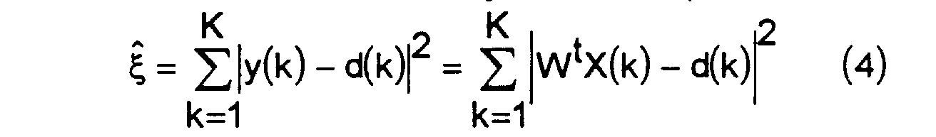
- y(k) est la sortie de l'antenne adaptative et est définie par
- W est le vecteur poids définissant l'antenne adaptative, Wt étant le vecteur transposé conjugué correspondant. (le signe t en exposant définit l'opérateur correspondant.)
- X(k) est le vecteur formé par les signaux reçus sur les capteurs.
- d(k) est le signal de réplique connu.
- y (k) is the output of the adaptive antenna and is defined by
- W is the weight vector defining the adaptive antenna, W t being the corresponding conjugate transposed vector. (the sign t in exponent defines the corresponding operator.)
- X (k) is the vector formed by the signals received on the sensors.
- d (k) is the known replica signal.
La différence y(k) - d(k) est obtenue sur la figure 2 à la sortie d'un circuit
soustracteur 5.The difference y (k) - d (k) is obtained in figure 2 at the output of a
Le vecteur poids W est calculé par la formule connue de Wiener :


L'antenne adaptative ainsi utilisée conduit à une maximisation du rapport signal/(bruit + interférence) connu sous la désignation SNIR abréviation anglo-saxonne de "Signal to Noise + Interference Ratio" obtenu en sortie de l'antenne, avec une possibilité de réjection pouvant aller jusqu'à N1 brouilleurs, et est appelée Filtre Adapté Spatial (FAS).The adaptive antenna thus used leads to a maximization of the signal / (noise + interference) ratio known by the designation SNIR abbreviation Anglo-Saxon "Signal to Noise + Interference Ratio" obtained in antenna output, with the possibility of rejection up to N1 jammers, and is called Spatial Adaptive Filter (FAS).
La recherche de la synchronisation est effectuée selon l'invention en
sortie de l'antenne adaptative en discriminant le signal selon sa modulation,
et en utilisant le critère de synchronisation mono-capteur. Le schéma de
principe de la synchronisation spatiale est représenté à la figure 3 où les
éléments homologues à ceux des figures 1 et 2 sont représentés avec les
mêmes références. Le critère de synchronisation devient, en utilisant les
notations précédentes :

y(k+n) représente la sortie de l'antenne adaptative conduisant à une
minimisation de l'erreur quadratique moyenne ξ and(n) estimée sur K échantillons
entre la réplique d(k) et le signal arrivant pris à partir de l'échantillon
n, suivant la relation

Les différentes corrélations sont calculées sur les K échantillons qui
suivent l'arrivée d'un échantillon n suivant les relations :


Lorsque l'échantillon n correspond à la position de synchronisation, les poids W(n) définissent le filtre adapté, et y(k+n) contient alors le signal utile débarrassé de la contribution des brouilleurs. Dans le cas contraire, aucun signal n'est corrélé avec la réplique d(k) et y(k+n) ne contient plus alors que la contribution du bruit de fond.When the sample n corresponds to the synchronization position, the weights W (n) define the adapted filter, and y (k + n) then contains the signal useful rid of the contribution of the jammers. Otherwise, no signal is correlated with the replica d (k) and y (k + n) no longer contains while the contribution of background noise.
L'expression du critère de synchronisation spatiale se simplifie en
écrivant :

De même que pour le cas mono-capteur, ce calcul est réitéré pour chaque échantillon n, et lorsque le critère C(n) dépasse un certain seuil η, dépendant de la probabilité de fausse alarme, la synchronisation est décidée (la normalisation par la puissance est ici obtenue par l'intermédiaire de R -1 / XX).As for the single-sensor case, this calculation is repeated for each sample n, and when the criterion C (n) exceeds a certain threshold η, depending on the probability of a false alarm, synchronization is decided (normalization by power is obtained here through R -1 / XX).
L'instant de synchronisation est alors déterminé par le rang de l'échantillon pour lequel C(n0) est supérieur à une valeur de seuil déterminée η.The synchronization instant is then determined by the rank of the sample for which C (n 0 ) is greater than a determined threshold value η.
Les calculs correspondant sont effectués sur la figure 3 par le bloc 7 de calcul du critère C(n) et par le détecteur de seuil 8, à partir de la séquence de synchronisation d(t) et du signal y(t) corrélés par le corrélateur 6.The corresponding calculations are carried out in FIG. 3 by block 7 for calculating criterion C (n) and by the threshold detector 8, from the synchronization sequence d (t) and of the signal y (t) correlated by the correlator 6.
Cela nécessite pour chaque échantillon, d'une part de calculer N corrélations entre le signal de réplique d(k) et les signaux x(k) reçus par les N capteurs (soit N fois les calculs effectués pour la synchronisation mono-capteur), et d'autre part, d'estimer puis d'inverser la matrice d'intercorrélation des signaux capteurs.This requires for each sample, on the one hand to calculate N correlations between the replica signal d (k) and the signals x (k) received by the N sensors (ie N times the calculations made for the mono-sensor synchronization), and on the other hand, to estimate then to invert the intercorrelation matrix of the sensor signals.
Au cours de ces calculs la synchronisation et le calcul du filtre adapté
2 sont effectués conjointement. Lorsque la valeur du critère dépasse le seuil
η, calculé, la synchronisation est décidée et le vecteur poids définissant le
filtre 2 s'en déduit facilement par la formule connue de Wiener. Le vecteur
poids W peut ensuite être utilisé pour filtrer les échantillons contenant l'information.During these calculations the synchronization and the calculation of the adapted
En supposant que la réplique d(t) est de puissance 1, les corrélations
tendent vers les valeurs suivantes, lorsque le nombre d'échantillons K
devient très grand :
- R est la matrice de corrélation des interférences et du bruit de fond,
- S est la matrice du vecteur directeur du signal utile,
- πs est la puissance du signal utile reçu sur un capteur.
- R is the interference and background noise correlation matrix,
- S is the matrix of the directional vector of the useful signal,
- π s is the power of the useful signal received on a sensor.
Le critère de synchronisation qui converge alors vers une valeur C0
s'écrit encore :
Lorsque le SNIR est fort, le critère tend vers 1, lorsqu'il est faible, il tend vers 0. L'importance du choix du seuil η, fixe la probabilité de détection de la synchronisation. Le seuil dépend naturellement de la probabilité de fausse alarme souhaitée.When the SNIR is strong, the criterion tends towards 1, when it is weak, it tends towards 0. The importance of the choice of the threshold η, fixes the probability of detection synchronization. The threshold naturally depends on the probability of false alarm desired.
Le calcul du critère de synchronisation C, de r andXd et de R andXX est effectué pour chaque position de la synchronisation et notamment la matrice R andXX est estimée et inversée également pour chaque position de la synchronisation, la puissance de calcul demandée est élevée. Mais il est possible de réduire la puissance de calcul en estimant la matrice de corrélation R andXX moins souvent sur un intervalle de temps plus important (K' échantillons au lieu de K avec K'>K de la façon représentée à la figure 4) et en utilisant cette estimation de R andXX sur toutes les positions de synchronisation incluses dans cet intervalle de temps.The calculation of the synchronization criterion C, of r and Xd and of R and XX is carried out for each position of the synchronization and in particular the matrix R and XX is estimated and also reversed for each position of the synchronization, the requested computing power is high. But it is possible to reduce the computing power by estimating the correlation matrix R and XX less often over a longer time interval (K 'samples instead of K with K'> K as shown in Figure 4) and using this estimate of R and XX on all the synchronization positions included in this time interval.
Dans ces conditions la matrice R andXX s'écrit :

- B(tk) est la contribution du bruit et des brouilleurs sur X(tk),
- S(tk) est la contribution du signal utile sur X(tk),
- K0 est l'instant d'apparition du signal utile sur le palier,
- ε est un terme prenant en compte l'intercorrélation entre le signal B(t) et le signal utile S(t), qui tend vers 0 lorsque K devient grand.
- B (t k ) is the contribution of noise and interferers on X (t k ),
- S (t k ) is the contribution of the useful signal on X (t k ),
- K 0 is the instant of appearance of the useful signal on the landing,
- ε is a term taking into account the intercorrelation between the signal B (t) and the useful signal S (t), which tends towards 0 when K becomes large.
Pour la position de synchronisation testée :

Dans les conditions asymptotiques (avec K>>1), lorsque le signal
utile est synchronisé avec la réplique d(t), R andXX et r andXd se simplifient et
s'écrivent :
Le critère obtenu en estimant la matrice de corrélation RXX sur K'
échantillons possède comme valeur asymptotique, après un calcul utilisant
le lemme d'inversion matricielle :
Comme
La valeur du critère apparaít dans ces conditions augmentée d'un facteur dépendant de l'instant d'apparition du signal utile sur la fréquence considérée, ce qui entraíne une amélioration de la prise de synchronisation, au prix d'une puissance de calcul réduite.The value of the criterion appears in these conditions increased by one factor depending on the instant of appearance of the useful signal on the frequency considered, which leads to an improvement in the synchronization socket, at the cost of reduced computing power.
D'autre part, le nombre K' ne doit pas être choisi trop grand, sa valeur est déterminée pour que sur K' échantillons, l'environnement de brouillage puisse être considéré comme stationnaire.On the other hand, the number K 'should not be chosen too large, its value is determined so that on K 'samples, the interference environment can be considered stationary.
Le seuil à prendre en considération dépend de la probabilité de fausse alarme (Pfa). La (Pfa) est la probabilité qu'un bruit soit détecté comme une synchronisation. Le calcul de la valeur du seuil η a lieu en calculant Pfa=P(C>η) lorsque l'antenne reçoit uniquement du bruit.The threshold to be taken into account depends on the probability of false alarm (Pfa). La (Pfa) is the probability that a noise will be detected like a synchronization. The threshold value η is calculated by calculating Pfa = P (C> η) when the antenna receives only noise.
En présence de bruit, le critère de synchronisation s'écrit :
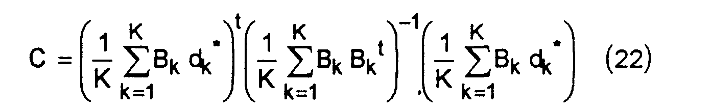
En supposant que Bk est un bruit gaussien complexe de puissance
σ2, indépendant entre les capteurs, lorsque K est suffisamment grand, le
terme du milieu de la relation (22) devient :


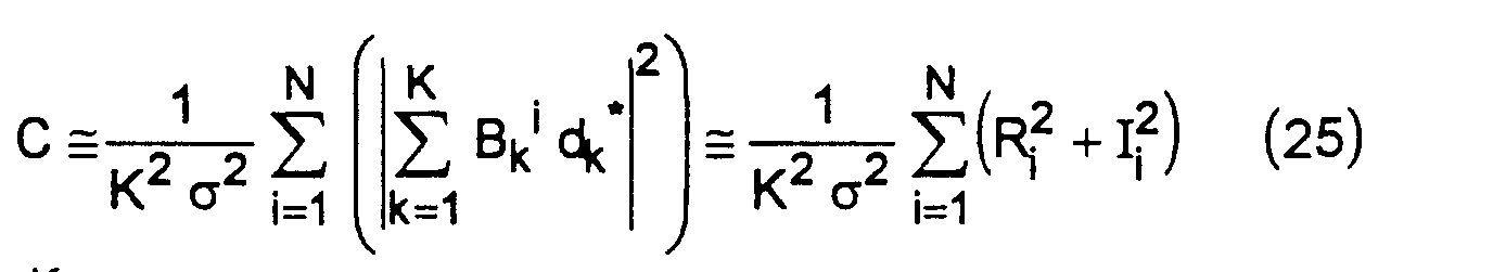


Comme la suite des Zi peut être considérée comme une suite de 2N
variables aléatoires indépendantes gaussiennes de moyennes nulles et de
variances 1, la variable aléatoire
![]()
![]()
La probabilité d'avoir C ≥ n s'écrit alors :

Le tableau suivant donne différentes valeurs de seuils η obtenues par
recherche dans une table donnant P(Z≥A) pour une loi du χ2 à 2N degrés de
liberté et pour Pfa = 10-5
Comme entre l'émission et la réception, le signal transmis peut être affecté d'un certain décalage en fréquence, ou décalage Doppler, dû essentiellement aux dérives en fréquences des oscillateurs locaux des synthétiseurs à l'émission et à la réception, ainsi qu'aux conditions de propagation ionosphérique, il est nécessaire de compenser ce décalage. Le risque est s'il n'est pas compensé, d'empêcher toute prise de synchronisation.As between transmission and reception, the transmitted signal can be affected by a certain frequency shift, or Doppler shift, mainly due frequency drift of local synthesizer oscillators on transmission and reception, as well as on propagation conditions ionospheric, it is necessary to compensate for this shift. The risk is if it is not compensated, to prevent any synchronization taking.
En appelant Δf0, le décalage Doppler entre le signal reçu par l'antenne
et le signal attendu et en considérant la position de synchronisation, le
vecteur signal reçu peut s'écrire avec les notations des paragraphes suivants
:
La matrice de corrélation estimée peut alors s'écrire :


La relation (32) montre que le décalage Doppler ne modifie pas le calcul de RXX. En effet, le décalage s'élimine naturellement lorsque le signal utile est multiplié par sa quantité conjuguée.The relation (32) shows that the Doppler shift does not modify the calculation of R XX . In fact, the offset is naturally eliminated when the useful signal is multiplied by its combined quantity.
Le vecteur d'intercorrélation peut s'écrire :


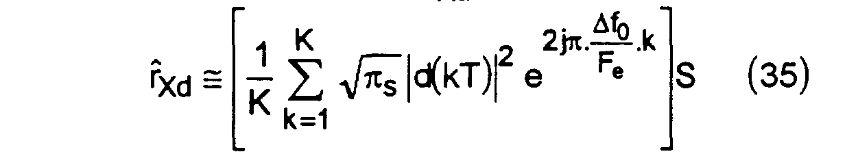
La relation (34) montre que le décalage Doppler modifie l'estimation du vecteur d'intercorrélation rXd et que du fait que la phase du terme en exponentiel complexe peut tourner de plusieurs fois 360° sur l'intervalle de temps utilisé pour le calcul de la corrélation, l'intégration ne peut plus avoir lieu de façon cohérente ce qui empêche le critère de synchronisation multi-capteurs de converger. Le processus suivant permet d'estimer le décalage Doppler et de le compenser pour rendre possible la prise de synchronisation.The relation (34) shows that the Doppler shift modifies the estimation of the intercorrelation vector r Xd and that the fact that the phase of the term in complex exponential can rotate several times 360 ° over the time interval used for the calculation from the correlation, integration can no longer take place in a coherent manner which prevents the multi-sensor synchronization criterion from converging. The following process makes it possible to estimate the Doppler shift and to compensate for it to make it possible to take synchronization.
Selon ce processus, les K symboles de la séquence de synchronisation sont découpés de la façon représentée à la figure 5 en M tranches de K0 symboles (M K0 = K), de telle sorte que sur chacune des tranches de K0 symboles, le décalage Doppler fasse tourner la phase du signal reçu par l'antenne d'une valeur inférieure à 90°, afin de permettre une intégration cohérente de rXd sur chacune des tranches.According to this process, the K symbols of the synchronization sequence are divided as shown in FIG. 5 into M slices of K 0 symbols (MK 0 = K), so that on each of the slices of K 0 symbols, the Doppler shift rotates the phase of the signal received by the antenna by a value less than 90 °, in order to allow a coherent integration of r Xd on each of the slices.
Si rXdi désigne la valeur de l'intercorrélation estimée sur la tranche i,
celle-ci s'écrit :

En mettant en facteur dans la relation (36) un terme dépendant uniquement
de K0, la longueur de la tranche élémentaire considérée, et du
décalage Doppler, la relation (36) devient :

Ce qui peut encore s'écrire :
La relation (38) montre que les vecteurs rXdi sont des vecteurs,
échantillonnés à Fe / K0. Leur transformée de Fourier discrète est alors :


La relation (40) montre que lorsque Δf = Δf0, le décalage Doppler est compensé, ce qui rend maximum la valeur du critère de synchronisation rXd(Δf)tRXX -1rXd(Δf).The relation (40) shows that when Δf = Δf 0 , the Doppler shift is compensated, which maximizes the value of the synchronization criterion r Xd (Δf) t R XX -1 r Xd (Δf).
Afin d'estimer Δf, c'est-à-dire afin d'estimer le décalage Doppler qui
conduit à la valeur maximale du critère, et afin de réduire le coût de calcul
correspondant, une transformée de Fourier rapide est effectuée sur les
vecteurs rXdi (le nombre de tranches élémentaires M étant choisi pour former
une puissance de 2) : ce calcul donne :

Si la résolution est insuffisante, une amélioration d'un facteur 2 peut
être obtenue en calculant une transformée de Fourier rapide, sur les vecteurs
rXdi "décalées" en fréquence de la façon suivante :

L'opération consiste à multiplier chacun des vecteurs d'intercorrélation rXdi par le terme e-(jπi/M) et à effectuer ensuite un calcul de transformée rapide sur les vecteurs ainsi obtenus.The operation consists in multiplying each of the intercorrelation vectors r Xdi by the term e - (jπi / M) and then in performing a fast transform calculation on the vectors thus obtained.
Le critère de synchronisation est ensuite estimé sur chacune des
cases de calcul des transformées de Fourier précédentes par la relation :
![]()
![]()
Bien évidemment, si la résolution est toujours insuffisante, il est possible
de l'améliorer en utilisant le même processus pour calculer des vecteurs
![]()
![]()
Un test sur la case de la transformée correspondant au maximum du
critère de synchronisation est effectué. Si le seuil est dépassé pour une
valeur k0
Δf1 / 2 donnée du décalage Doppler, il est alors possible d'affiner le
calcul du décalage Doppler (indispensable pour la démodulation) en calculant
la valeur du critère pour différentes valeurs de décalage Doppler entourant
k0 Δf1 / 2. En effet, à l'issue de cette étape, la résolution sur l'estimation
du décalage Doppler est Δf1 / 2. Pour l'améliorer, il faut procéder par dichotomie
: à chaque itération et de la façon représentée à la figure 6, la valeur du
critère pour la valeur de décalage Doppler située au milieu des deux valeurs
de décalage Doppler donnant les valeurs maxima du critère lors de l'itération
précédente est calculée. La recherche par dichotomie est arrêtée dès que la
résolution souhaitée sur l'estimation du décalage Doppler est obtenue.
Après n itérations de l'algorithme de recherche par dichotomie, la résolution,
qui était initialement de Δf1 / 2, est :
L'enchaínement des étapes de calcul précédente pour la mise en oeuvre du procédé selon l'invention à l'aide de moyens de traitement appropriés formés par exemple par des processeurs de traitement du signal ou tout dispositif équivalent connu est figuré sur l'organigramme de la figure 7.The sequence of previous calculation steps for setting work of the method according to the invention using processing means suitable trained for example by signal processing processors or any known equivalent device is shown on the organization chart of the figure 7.
Il consiste suivant l'étape 9 à estimer la matrice de corrélation R andXX suivant la relation (7). Cette matrice est estimée sur un bloc contenant un nombre d'échantillons K' supérieur au nombre d'échantillons de la séquence de synchronisation.It consists, according to step 9, in estimating the correlation matrix R and XX according to the relation (7). This matrix is estimated on a block containing a number of samples K ′ greater than the number of samples of the synchronization sequence.
L'estimation de RXX est utilisée ensuite pour toutes les positions de
synchronisation incluses dans le bloc. Puis la matrice de corrélation inverse
R and -1 / XX est calculée à l'étape 10. r andXdi qui est défini par la relation (8) est calculé
à l'étape 11. Pour chaque échantillon correspondant à une position de synchronisation
P dans la suite des échantillons P = 1 à P = K'-K, r andXdi est calculé
pour i = 1 à M sur M blocs de K0 symboles comme défini à la figure 5 suivant
la relation

Des calculs de transformée de Fourier Rapide sont effectués à l'étape
suivante 12 sur un nombre déterminé M (M = 8 par exemple) de vecteurs
r andXdi suivant la relation (41).Fast Fourier transform calculations are performed in the
Aux étapes 13 et 14 un calcul de vecteur r andXdi décalé et un calcul de
transformée de Fourier rapide suivant la relation (43) sont exécutés pour
améliorer la résolution par un facteur de 2.In
Le critère de synchronisation est calculé à l'étape 15 en application
de la relation (44).The synchronization criterion is calculated in
La comparaison du critère ou seuil η est effectuée à l'étape 16. Si à
l'étape 16 la valeur du critère
![]()
![]()
![]()
![]()
La recherche de synchronisation précédemment décrite est effectuée
pour chacun des échantillons de signal numérisé. En pratique, pour améliorer
la précision de la position de la synchronisation il est préférable d'effectuer
un suréchantillonnage du signal d'un facteur déterminé L, L étant égal à
4 par exemple. Les traitements de l'organigramme de la figure 7 et décrits ci-dessus
sont encore utilisables sur le signal ainsi suréchantillonné, mais il est
possible d'utiliser une variante dans le procédé, afin de réduire la puissance
de calcul nécessaire au traitement. Dans ces conditions, après avoir calculé
pour chaque échantillon le vecteur r andXdi pour i = 1, ... M sur M blocs de K0
symboles suivant la relation (46) un critère de synchronisation C; est calculé
sur chacun des M blocs par la relation
Puis un critère somme de l'ensemble des Ci est calculé suivant la
relation :

Ce critère correspond à une intégration non cohérente des Ci (contrairement à ce qui est fait pour le calcul par FFT où on intègre de façon cohérente), ce qui se traduit par une remontée du critère sur les échantillons de bruit.This criterion corresponds to a non-coherent integration of the Ci (unlike what is done for the calculation by FFT where we integrate so consistent), which results in an increase in the criterion on the samples noise.
Le calcul du critère a lieu par blocs de L échantillons consécutifs. Sur
chacun de ces blocs, l'échantillon qui donne la valeur maximum de C1(P) est
sélectionné pour effectuer le calcul par transformée de Fourier rapide
nécessaire à l'estimation du décalage Doppler comme déjà décrit aux étapes
11 à 19 de la figure 7.The criterion is calculated by blocks of L consecutive samples. On each of these blocks, the sample which gives the maximum value of C 1 (P) is selected to carry out the calculation by fast Fourier transform necessary for the estimation of the Doppler shift as already described in
Claims (8)
- Method enabling a modem to be synchronized with an RF digital signal transmitter in the presence of jammers consisting in:estimating (9) the matrix of correlation R and xx of signals received on a set of N reception sensors (11 ... 1 N ) by blocks formed by a number of samples of a synchronization sequence transmitted by the transmitter,Computing (10) the reverse correlation matrix R and xx -1,computing (11) vectors of intercorrelation r andxd between the signals X(k) received on the set of the N sensors and a known replica signal d(k),computing a criterion of synchronization (7) calculating the scalar product between the intercorrelation vector r XD and the vector obtained by the product of the inverse of the correlation matrix R and xx -1 and the intercorrelation vector r xd ,comparing (8) the value of the criterion obtained with a determined threshold value η to place the synchronization on the sample for which the value of the criteria exceeds the threshold value η,
characterized in that, in order to estimate the Doppler shift inherent in the communications between transmitters and receivers, said method consists in subdividing the synchronization sequence into a determined number M of sections of ko symbols,carrying out (11, 13) computations, on these sections, of partial intercorrelation vectors r andxd (i = 1 ... M) in such a way that, on each of the sections of ko symbols, the Doppler shift causes the phase to rotate by a value of less than 90°,carrying out (12, 14) fast Fourier transform (FFT) computations on the vectors r andxdi obtained,and computing a value of the synchronization criterion from the vectors rxd (kΔf), obtained as a result of the fast Fourier transform computations and the correlation matrix R andxx. - Method according to Claim 1, characterized in that the estimation of the correlation matrix R andxx is obtained by the relationshipand the intercorrelation vector is estimated according to the relationship.
 where p is the position of the first sample from which the correlation is done between the vector X and the replica d.
- Method according to Claim 2, consisting in choosing the computation bin of the fast Fourier transform that gives a maximum value of the synchronization criterion and in comparing the maximum value obtained with a determined threshold value to decide on the synchronization.
- Method according to any one of Claims 1 to 3, characterized in that to obtain an improved resolution on the Doppler shift and a greater value of the maximum of the criterion, consists in computing (13) frequency-shifted vectors r xdi and in performing an FFT computation on the shifted vectors rxdi so as to obtain the value of the criterion with higher resolution on the Doppler frequencies.
- Method according to any one of Claims 1 to 4 characterized in that it consists in oversampling the signals received on the N sensors with respect to the symbol rate to improve the resolution on the synchronization position.
- Method according to any one of Claims 1 to 5, characterized in that it consists in computing the correlation matrix R and xx on a number of samples K' greater than the number K of samples of the synchronization sequence in order to reduce the computing power.
- Method according to any one of Claims 1 to 6, characterized in that in order to reduce the computing power and after having carried out an oversampling by a factor L with respect to the symbol rate, it consists in carrying out a pre-treatment step consisting of the computation, for each sample p (p = 1 to L) forming a symbol, of the values Ci of the criterion of synchronization on each of the M sections of k0 symbols and computing the value of the criterion by taking the sum of the criteria Ci obtained to keep, in the subsequent processing, the sample giving the maximum value of the criterion: C = ΣCi .
- Device for implementing the method according to any one of Claims 1 to 7 of the type comprising a network of N sensors (11...1 N ) of reception signals coupled with a network of adaptive filters comprising amplitude-phase weighting circuits controlled by a control processor, the control processor being programmed to:estimate the inverse matrix of correlation R andxx -1 of the received signals X(K) and compute the vectors of intercorrelation r andxd between the signals X(k) and the replica signal d(k) characterized in that it comprises processing means (5...19) to compute a criterion of synchronization (7) by calculating the scalar product between the intercorrelation vector r xd and the vector obtained by the product of the inverse of the correlation matrix R xx -1 and the intercorrelation vector r andxd, compare (8) the value of the criterion obtained with the threshold value η to place the synchronization on the sample for which the value of the criteria exceeds the threshold value η,and estimate the Doppler shift inherent in the communications between transmitters and receivers by subdividing the synchronization into a determined number M of sections of ko symbols,carrying out (11, 13) computation on these sections, of partial intercorrelations vectors r andxd (i = 1...M) in such a way that, on each of the sections of ko symbols, the Doppler shift causes the phase to rotate by a value of less than 90°,carrying out (12, 14) fast Fourier transform (FFT) computations on the vectors r andxdi obtained,and computing a value of the synchronization criterion from the vectors r xd (kΔf), obtained as a result of the fast Fourier transform computations and the correlation matrix R andxx.
Applications Claiming Priority (2)
| Application Number | Priority Date | Filing Date | Title |
|---|---|---|---|
| FR9400634 | 1994-01-21 | ||
| FR9400634A FR2715488B1 (en) | 1994-01-21 | 1994-01-21 | Method and device enabling a modem to synchronize with a digital data transmitter over the air in the presence of jammers. |
Publications (2)
| Publication Number | Publication Date |
|---|---|
| EP0665665A1 EP0665665A1 (en) | 1995-08-02 |
| EP0665665B1 true EP0665665B1 (en) | 2001-05-16 |
Family
ID=9459254
Family Applications (1)
| Application Number | Title | Priority Date | Filing Date |
|---|---|---|---|
| EP95400070A Expired - Lifetime EP0665665B1 (en) | 1994-01-21 | 1995-01-13 | Method and device enabling a modem to synchronize on a transmitter of digital data via a radio channel in the presence of interferences |
Country Status (5)
| Country | Link |
|---|---|
| US (1) | US5812090A (en) |
| EP (1) | EP0665665B1 (en) |
| DE (1) | DE69520895T2 (en) |
| FR (1) | FR2715488B1 (en) |
| NO (1) | NO308637B1 (en) |
Cited By (7)
| Publication number | Priority date | Publication date | Assignee | Title |
|---|---|---|---|---|
| US6600914B2 (en) | 1999-05-24 | 2003-07-29 | Arraycomm, Inc. | System and method for emergency call channel allocation |
| US6654590B2 (en) | 1998-05-01 | 2003-11-25 | Arraycomm, Inc. | Determining a calibration function using at least one remote terminal |
| US6690747B2 (en) | 1996-10-11 | 2004-02-10 | Arraycomm, Inc. | Method for reference signal generation in the presence of frequency offsets in a communications station with spatial processing |
| US7751854B2 (en) | 1999-06-21 | 2010-07-06 | Intel Corporation | Null deepening for an adaptive antenna based communication station |
| US8064944B2 (en) | 1996-10-11 | 2011-11-22 | Intel Corporation | Power control with signal quality estimation for smart antenna communications systems |
| RU2457506C2 (en) * | 2007-08-08 | 2012-07-27 | Таль | Methods and apparatus for determining pulse characteristic of propagation channels in presence of radiators, reflectors and sensitive elements, fixed or mobile |
| EP3188426A1 (en) | 2015-12-29 | 2017-07-05 | Thales | Method for controlling adaptive interference in a multi-channel receiver |
Families Citing this family (31)
| Publication number | Priority date | Publication date | Assignee | Title |
|---|---|---|---|---|
| US6463295B1 (en) | 1996-10-11 | 2002-10-08 | Arraycomm, Inc. | Power control with signal quality estimation for smart antenna communication systems |
| US5930243A (en) * | 1996-10-11 | 1999-07-27 | Arraycomm, Inc. | Method and apparatus for estimating parameters of a communication system using antenna arrays and spatial processing |
| US6335954B1 (en) | 1996-12-27 | 2002-01-01 | Ericsson Inc. | Method and apparatus for joint synchronization of multiple receive channels |
| FR2758926B1 (en) * | 1997-01-24 | 1999-04-30 | France Telecom | METHOD OF MULTI-SENSOR EQUALIZATION IN A RADIOELECTRIC RECEIVER HAVING A DETERMINED NUMBER OF RECEPTION PATHWAYS AND CORRESPONDING RECEIVER |
| FR2762164B1 (en) * | 1997-04-14 | 1999-09-24 | Nortel Matra Cellular | TIME-WEIGHTED PROBING OF A TRANSMISSION CHANNEL |
| FR2764074B1 (en) | 1997-06-03 | 1999-08-20 | Thomson Csf | TRANSMISSION COOPERATIVE RADIOGONIOMETRY METHOD AND DEVICE |
| FR2766320B1 (en) | 1997-07-15 | 1999-10-15 | Thomson Csf | METHOD AND DEVICE FOR ANALYZING INTERFERENCE IN A CELLULAR RADIO COMMUNICATION SYSTEM |
| US6501747B1 (en) * | 1998-08-20 | 2002-12-31 | Metawave Communications Corporation | Manifold assisted channel estimation and demodulation for CDMA systems in fast fading environments |
| JP2000354079A (en) * | 1999-04-28 | 2000-12-19 | Texas Instr Inc <Ti> | Multiple sampling frame synchronization inside wire line modem |
| US7412018B1 (en) * | 1999-05-26 | 2008-08-12 | Alcatel Usa Sourcing, L.P. | Rapid acquisition synchronization sequences for direct sequence spread spectrum systems using code time offsets |
| FI19992653A (en) * | 1999-12-09 | 2001-06-10 | Nokia Mobile Phones Ltd | A method for synchronizing a receiver and a receiver |
| FI111109B (en) * | 1999-12-09 | 2003-05-30 | Nokia Corp | Method for synchronizing a receiver, location system, receiver and electronic device |
| FI112893B (en) | 1999-12-21 | 2004-01-30 | Nokia Corp | Method in receiver and receiver |
| FR2806499B1 (en) * | 2000-03-20 | 2003-10-10 | Thomson Csf | METHOD FOR ESTIMATING AN INTERFERENT SIGNAL CORRELATION MATRIX RECEIVED BY A SENSOR ARRAY |
| US7043259B1 (en) | 2000-09-29 | 2006-05-09 | Arraycomm, Inc. | Repetitive paging from a wireless data base station having a smart antenna system |
| US6795409B1 (en) | 2000-09-29 | 2004-09-21 | Arraycomm, Inc. | Cooperative polling in a wireless data communication system having smart antenna processing |
| FR2819357B1 (en) * | 2001-01-09 | 2016-02-12 | Thomson Csf | AUTODIDACTIVE METHOD AND RECEIVER FOR DETERMINING SPATIO-TEMPORAL PARAMETERS OF A PROPAGATION CHANNEL |
| FR2820580B1 (en) | 2001-02-02 | 2004-06-04 | Thomson Csf | METHOD FOR ESTIMATING THE PARAMETERS OF A SPREAD CHANNEL |
| FR2821502A1 (en) * | 2001-02-27 | 2002-08-30 | Thomson Csf | METHOD AND DEVICE FOR ESTIMATING A PROPAGATION CHANNEL FROM ITS STATISTICS |
| FR2824431A1 (en) * | 2001-05-03 | 2002-11-08 | Mitsubishi Electric Inf Tech | METHOD AND DEVICE FOR RECEIVING SIGNAL |
| CN1283059C (en) * | 2003-01-23 | 2006-11-01 | 上海贝尔阿尔卡特股份有限公司 | Method and equipment for carrier frequency synchronization |
| FR2854290B1 (en) | 2003-04-25 | 2005-08-26 | Thales Sa | METHOD OF DEMODULATING OFDM-TYPE SIGNALS IN THE PRESENCE OF STRONG CO-CHANNEL BROKERS |
| FR2866509B1 (en) * | 2004-02-13 | 2006-04-28 | Thales Sa | METHOD OF OPTIMIZING PLANNING IN A CDMA TYPE COMMUNICATIONS SYSTEM |
| US20050232340A1 (en) * | 2004-04-16 | 2005-10-20 | Lucent Technologies, Inc. | Intelligent antenna receiver architecture |
| FR2882479B1 (en) * | 2005-02-22 | 2007-04-20 | Thales Sa | METHOD AND DEVICE FOR SYNCHRONIZING RECTILIGNED OR QUASI-RECTILINE LINKS IN THE PRESENCE OF INTERFERENCE |
| FR2891683B1 (en) * | 2005-10-05 | 2008-02-08 | Eads Telecom Soc Par Actions S | OFDM RECEPTION IN MULTI ANTENNA MODE |
| US20100117884A1 (en) * | 2008-11-11 | 2010-05-13 | Qualcomm Incorporated | Method for performing consistency checks for multiple signals received from a transmitter |
| FR2954515B1 (en) * | 2009-12-23 | 2012-08-17 | Thales Sa | METHOD AND DEVICE FOR SIGNAL GONIOMETRY INTERFERING A USEFUL SIGNAL MODULATED BY MULTIPLE CARRIERS. |
| US10705176B2 (en) * | 2015-10-13 | 2020-07-07 | Northrop Grumman Systems Corporation | Signal direction processing for an antenna array |
| FR3061617A1 (en) | 2016-12-29 | 2018-07-06 | Thales | METHOD FOR INTERFERENCE CONTROL BY SPATIAL FILTRATION OR SPATIO-TEMPORAL FILTERING IN A MULTI-CHANNEL RECEIVER |
| CN114553417B (en) * | 2022-03-22 | 2024-01-09 | 上海循态量子科技有限公司 | Regular component pre-calibration method and system in continuous variable quantum key distribution system |
Family Cites Families (4)
| Publication number | Priority date | Publication date | Assignee | Title |
|---|---|---|---|---|
| US4752969A (en) * | 1986-01-16 | 1988-06-21 | Kenneth Rilling | Anti-multipath signal processor |
| US5144322A (en) * | 1988-11-25 | 1992-09-01 | The United States Of America As Represented By The Secretary Of The Navy | Large-aperture sparse array detector system for multiple emitter location |
| DE4130863C2 (en) * | 1991-09-17 | 1999-04-15 | Daimler Benz Aerospace Ag | Digital messaging system |
| US5481505A (en) * | 1995-05-15 | 1996-01-02 | The United States Of America As Represented By The Secretary Of The Navy | Tracking system and method |
-
1994
- 1994-01-21 FR FR9400634A patent/FR2715488B1/en not_active Expired - Fee Related
-
1995
- 1995-01-13 EP EP95400070A patent/EP0665665B1/en not_active Expired - Lifetime
- 1995-01-13 DE DE69520895T patent/DE69520895T2/en not_active Expired - Lifetime
- 1995-05-23 NO NO952033A patent/NO308637B1/en not_active IP Right Cessation
-
1997
- 1997-06-27 US US08/882,831 patent/US5812090A/en not_active Expired - Lifetime
Cited By (9)
| Publication number | Priority date | Publication date | Assignee | Title |
|---|---|---|---|---|
| US6690747B2 (en) | 1996-10-11 | 2004-02-10 | Arraycomm, Inc. | Method for reference signal generation in the presence of frequency offsets in a communications station with spatial processing |
| US8064944B2 (en) | 1996-10-11 | 2011-11-22 | Intel Corporation | Power control with signal quality estimation for smart antenna communications systems |
| US6654590B2 (en) | 1998-05-01 | 2003-11-25 | Arraycomm, Inc. | Determining a calibration function using at least one remote terminal |
| US6668161B2 (en) | 1998-05-01 | 2003-12-23 | Arraycomm, Inc. | Determining a spatial signature using a robust calibration signal |
| US6600914B2 (en) | 1999-05-24 | 2003-07-29 | Arraycomm, Inc. | System and method for emergency call channel allocation |
| USRE42224E1 (en) | 1999-05-24 | 2011-03-15 | Durham Logistics Llc | System and method for emergency call channel allocation |
| US7751854B2 (en) | 1999-06-21 | 2010-07-06 | Intel Corporation | Null deepening for an adaptive antenna based communication station |
| RU2457506C2 (en) * | 2007-08-08 | 2012-07-27 | Таль | Methods and apparatus for determining pulse characteristic of propagation channels in presence of radiators, reflectors and sensitive elements, fixed or mobile |
| EP3188426A1 (en) | 2015-12-29 | 2017-07-05 | Thales | Method for controlling adaptive interference in a multi-channel receiver |
Also Published As
| Publication number | Publication date |
|---|---|
| NO308637B1 (en) | 2000-10-02 |
| FR2715488B1 (en) | 1996-03-22 |
| NO952033D0 (en) | 1995-05-23 |
| EP0665665A1 (en) | 1995-08-02 |
| DE69520895D1 (en) | 2001-06-21 |
| US5812090A (en) | 1998-09-22 |
| NO952033L (en) | 1995-11-27 |
| DE69520895T2 (en) | 2001-09-27 |
| FR2715488A1 (en) | 1995-07-28 |
Similar Documents
| Publication | Publication Date | Title |
|---|---|---|
| EP0665665B1 (en) | Method and device enabling a modem to synchronize on a transmitter of digital data via a radio channel in the presence of interferences | |
| EP2100161B1 (en) | Method for the multipath passive radar processing of an fm opportunity signal | |
| EP0681190B1 (en) | Method and systemfor discrete radar detection | |
| FR2975193A1 (en) | METHOD AND SYSTEM FOR LOCATING INTERFERENCES AFFECTING A SATELLITE RADIONAVIGATION SIGNAL | |
| EP2520949B1 (en) | Device for receiving a satellite positioning system including a function for detecting false locking | |
| EP1185004A1 (en) | Joint angle of arrival and channel estimation method | |
| EP2908155B1 (en) | Method for anti-jamming processing of a radio signal, related module and computer program | |
| WO2022002700A1 (en) | Target detection method for ground-penetrating radar and associated radar | |
| WO2012025306A1 (en) | Space-time multi-antenna and multi-correlator device for rejecting multi-paths in navigation systems | |
| FR2882479A1 (en) | Rectilinear signal e.g. amplitude modulation signal, synchronization method for e.g. identification friend foe system, involves defining decision criterion by taking into account non circular character of interferences of second order | |
| WO2007060223A1 (en) | Doppler tracking method and device for a wide band modem | |
| EP0849889B1 (en) | Method of multipath signal reception | |
| EP1085341B1 (en) | Method of treating navigation signals with multipath in a receiver with a plurality of antennas | |
| EP1229696B1 (en) | Channel parameters estimation using maximum likelihood estimation | |
| EP0010481A1 (en) | Method of and device for displaying moving targets, in particular in a variable PRF radar | |
| EP3400457B1 (en) | Method for deleting a signal coming from an on-board radar | |
| EP0323927B1 (en) | Method and apparatus for demodulating digital data transmitted by frequency hopping on an ionospheric transmission channel | |
| EP3345357A1 (en) | Method and device for mimo synchronisation in the presence of interferences | |
| FR2802043A1 (en) | RADIO CHANNEL ESTIMATION AND DEMODULATION DEVICES | |
| FR2735635A1 (en) | Multiple sensor spatial and temporal equalisation method for radio receiver | |
| FR2494855A1 (en) | Doppler radar for detecting targets in ground clutter - uses spectral analyser to process fast fourier transform algorithm using synchroniser to distinguish range gates | |
| FR2736487A1 (en) | Carrier wave detection system for digital telecommunication signal - uses estimator squaring device and determines differences between even sample pairs and odd sample pairs and determines power level for comparison with threshold | |
| EP1102083A1 (en) | Satellite positioning system receiver operating in presence of parasitic radio waves | |
| FR2819963A1 (en) | PARTICULATE RECEPTOR FOR THE OPTIMAL JOINT ESTIMATION OF DIGITAL AND CONTINUOUS INFORMATION IN PULSED MODULATION SIGNALS | |
| FR2739453A1 (en) | Adaptive search elimination system for pulse Doppler radar |
Legal Events
| Date | Code | Title | Description |
|---|---|---|---|
| PUAI | Public reference made under article 153(3) epc to a published international application that has entered the european phase |
Free format text: ORIGINAL CODE: 0009012 |
|
| AK | Designated contracting states |
Kind code of ref document: A1 Designated state(s): DE FR GB IT |
|
| 17P | Request for examination filed |
Effective date: 19950922 |
|
| GRAG | Despatch of communication of intention to grant |
Free format text: ORIGINAL CODE: EPIDOS AGRA |
|
| 17Q | First examination report despatched |
Effective date: 20000530 |
|
| GRAG | Despatch of communication of intention to grant |
Free format text: ORIGINAL CODE: EPIDOS AGRA |
|
| GRAG | Despatch of communication of intention to grant |
Free format text: ORIGINAL CODE: EPIDOS AGRA |
|
| GRAH | Despatch of communication of intention to grant a patent |
Free format text: ORIGINAL CODE: EPIDOS IGRA |
|
| GRAH | Despatch of communication of intention to grant a patent |
Free format text: ORIGINAL CODE: EPIDOS IGRA |
|
| GRAA | (expected) grant |
Free format text: ORIGINAL CODE: 0009210 |
|
| AK | Designated contracting states |
Kind code of ref document: B1 Designated state(s): DE FR GB IT |
|
| REF | Corresponds to: |
Ref document number: 69520895 Country of ref document: DE Date of ref document: 20010621 |
|
| ITF | It: translation for a ep patent filed |
Owner name: JACOBACCI & PERANI S.P.A. |
|
| GBT | Gb: translation of ep patent filed (gb section 77(6)(a)/1977) |
Effective date: 20010730 |
|
| RAP2 | Party data changed (patent owner data changed or rights of a patent transferred) |
Owner name: THALES |
|
| REG | Reference to a national code |
Ref country code: GB Ref legal event code: IF02 |
|
| PLBE | No opposition filed within time limit |
Free format text: ORIGINAL CODE: 0009261 |
|
| STAA | Information on the status of an ep patent application or granted ep patent |
Free format text: STATUS: NO OPPOSITION FILED WITHIN TIME LIMIT |
|
| 26N | No opposition filed | ||
| REG | Reference to a national code |
Ref country code: FR Ref legal event code: CD |
|
| REG | Reference to a national code |
Ref country code: FR Ref legal event code: CL |
|
| PGFP | Annual fee paid to national office [announced via postgrant information from national office to epo] |
Ref country code: IT Payment date: 20120118 Year of fee payment: 18 |
|
| PGFP | Annual fee paid to national office [announced via postgrant information from national office to epo] |
Ref country code: GB Payment date: 20130109 Year of fee payment: 19 Ref country code: DE Payment date: 20130109 Year of fee payment: 19 Ref country code: FR Payment date: 20130204 Year of fee payment: 19 |
|
| REG | Reference to a national code |
Ref country code: DE Ref legal event code: R119 Ref document number: 69520895 Country of ref document: DE |
|
| GBPC | Gb: european patent ceased through non-payment of renewal fee |
Effective date: 20140113 |
|
| REG | Reference to a national code |
Ref country code: DE Ref legal event code: R119 Ref document number: 69520895 Country of ref document: DE Effective date: 20140801 |
|
| PG25 | Lapsed in a contracting state [announced via postgrant information from national office to epo] |
Ref country code: DE Free format text: LAPSE BECAUSE OF NON-PAYMENT OF DUE FEES Effective date: 20140801 |
|
| REG | Reference to a national code |
Ref country code: FR Ref legal event code: ST Effective date: 20140930 |
|
| PG25 | Lapsed in a contracting state [announced via postgrant information from national office to epo] |
Ref country code: GB Free format text: LAPSE BECAUSE OF NON-PAYMENT OF DUE FEES Effective date: 20140113 Ref country code: FR Free format text: LAPSE BECAUSE OF NON-PAYMENT OF DUE FEES Effective date: 20140131 |
|
| PG25 | Lapsed in a contracting state [announced via postgrant information from national office to epo] |
Ref country code: IT Free format text: LAPSE BECAUSE OF NON-PAYMENT OF DUE FEES Effective date: 20140113 |