EP0666099B1 - Method of removing nitrogen oxides contained in exhaust gas - Google Patents
Method of removing nitrogen oxides contained in exhaust gas Download PDFInfo
- Publication number
- EP0666099B1 EP0666099B1 EP94914570A EP94914570A EP0666099B1 EP 0666099 B1 EP0666099 B1 EP 0666099B1 EP 94914570 A EP94914570 A EP 94914570A EP 94914570 A EP94914570 A EP 94914570A EP 0666099 B1 EP0666099 B1 EP 0666099B1
- Authority
- EP
- European Patent Office
- Prior art keywords
- catalyst
- exhaust gas
- per liter
- nitrogen oxides
- platinum
- Prior art date
- Legal status (The legal status is an assumption and is not a legal conclusion. Google has not performed a legal analysis and makes no representation as to the accuracy of the status listed.)
- Expired - Lifetime
Links
Images
Classifications
-
- F—MECHANICAL ENGINEERING; LIGHTING; HEATING; WEAPONS; BLASTING
- F01—MACHINES OR ENGINES IN GENERAL; ENGINE PLANTS IN GENERAL; STEAM ENGINES
- F01N—GAS-FLOW SILENCERS OR EXHAUST APPARATUS FOR MACHINES OR ENGINES IN GENERAL; GAS-FLOW SILENCERS OR EXHAUST APPARATUS FOR INTERNAL COMBUSTION ENGINES
- F01N3/00—Exhaust or silencing apparatus having means for purifying, rendering innocuous, or otherwise treating exhaust
- F01N3/08—Exhaust or silencing apparatus having means for purifying, rendering innocuous, or otherwise treating exhaust for rendering innocuous
- F01N3/0807—Exhaust or silencing apparatus having means for purifying, rendering innocuous, or otherwise treating exhaust for rendering innocuous by using absorbents or adsorbents
- F01N3/0871—Regulation of absorbents or adsorbents, e.g. purging
-
- B—PERFORMING OPERATIONS; TRANSPORTING
- B01—PHYSICAL OR CHEMICAL PROCESSES OR APPARATUS IN GENERAL
- B01D—SEPARATION
- B01D53/00—Separation of gases or vapours; Recovering vapours of volatile solvents from gases; Chemical or biological purification of waste gases, e.g. engine exhaust gases, smoke, fumes, flue gases, aerosols
- B01D53/34—Chemical or biological purification of waste gases
- B01D53/74—General processes for purification of waste gases; Apparatus or devices specially adapted therefor
- B01D53/86—Catalytic processes
- B01D53/8621—Removing nitrogen compounds
- B01D53/8625—Nitrogen oxides
- B01D53/8628—Processes characterised by a specific catalyst
-
- B—PERFORMING OPERATIONS; TRANSPORTING
- B01—PHYSICAL OR CHEMICAL PROCESSES OR APPARATUS IN GENERAL
- B01D—SEPARATION
- B01D53/00—Separation of gases or vapours; Recovering vapours of volatile solvents from gases; Chemical or biological purification of waste gases, e.g. engine exhaust gases, smoke, fumes, flue gases, aerosols
- B01D53/34—Chemical or biological purification of waste gases
- B01D53/92—Chemical or biological purification of waste gases of engine exhaust gases
- B01D53/94—Chemical or biological purification of waste gases of engine exhaust gases by catalytic processes
- B01D53/9481—Catalyst preceded by an adsorption device without catalytic function for temporary storage of contaminants, e.g. during cold start
-
- B—PERFORMING OPERATIONS; TRANSPORTING
- B01—PHYSICAL OR CHEMICAL PROCESSES OR APPARATUS IN GENERAL
- B01J—CHEMICAL OR PHYSICAL PROCESSES, e.g. CATALYSIS OR COLLOID CHEMISTRY; THEIR RELEVANT APPARATUS
- B01J23/00—Catalysts comprising metals or metal oxides or hydroxides, not provided for in group B01J21/00
- B01J23/38—Catalysts comprising metals or metal oxides or hydroxides, not provided for in group B01J21/00 of noble metals
- B01J23/54—Catalysts comprising metals or metal oxides or hydroxides, not provided for in group B01J21/00 of noble metals combined with metals, oxides or hydroxides provided for in groups B01J23/02 - B01J23/36
- B01J23/56—Platinum group metals
- B01J23/58—Platinum group metals with alkali- or alkaline earth metals
-
- B—PERFORMING OPERATIONS; TRANSPORTING
- B01—PHYSICAL OR CHEMICAL PROCESSES OR APPARATUS IN GENERAL
- B01J—CHEMICAL OR PHYSICAL PROCESSES, e.g. CATALYSIS OR COLLOID CHEMISTRY; THEIR RELEVANT APPARATUS
- B01J23/00—Catalysts comprising metals or metal oxides or hydroxides, not provided for in group B01J21/00
- B01J23/38—Catalysts comprising metals or metal oxides or hydroxides, not provided for in group B01J21/00 of noble metals
- B01J23/54—Catalysts comprising metals or metal oxides or hydroxides, not provided for in group B01J21/00 of noble metals combined with metals, oxides or hydroxides provided for in groups B01J23/02 - B01J23/36
- B01J23/56—Platinum group metals
- B01J23/63—Platinum group metals with rare earths or actinides
-
- B—PERFORMING OPERATIONS; TRANSPORTING
- B01—PHYSICAL OR CHEMICAL PROCESSES OR APPARATUS IN GENERAL
- B01J—CHEMICAL OR PHYSICAL PROCESSES, e.g. CATALYSIS OR COLLOID CHEMISTRY; THEIR RELEVANT APPARATUS
- B01J23/00—Catalysts comprising metals or metal oxides or hydroxides, not provided for in group B01J21/00
- B01J23/70—Catalysts comprising metals or metal oxides or hydroxides, not provided for in group B01J21/00 of the iron group metals or copper
- B01J23/89—Catalysts comprising metals or metal oxides or hydroxides, not provided for in group B01J21/00 of the iron group metals or copper combined with noble metals
- B01J23/8933—Catalysts comprising metals or metal oxides or hydroxides, not provided for in group B01J21/00 of the iron group metals or copper combined with noble metals also combined with metals, or metal oxides or hydroxides provided for in groups B01J23/02 - B01J23/36
- B01J23/8946—Catalysts comprising metals or metal oxides or hydroxides, not provided for in group B01J21/00 of the iron group metals or copper combined with noble metals also combined with metals, or metal oxides or hydroxides provided for in groups B01J23/02 - B01J23/36 with alkali or alkaline earth metals
-
- F—MECHANICAL ENGINEERING; LIGHTING; HEATING; WEAPONS; BLASTING
- F01—MACHINES OR ENGINES IN GENERAL; ENGINE PLANTS IN GENERAL; STEAM ENGINES
- F01N—GAS-FLOW SILENCERS OR EXHAUST APPARATUS FOR MACHINES OR ENGINES IN GENERAL; GAS-FLOW SILENCERS OR EXHAUST APPARATUS FOR INTERNAL COMBUSTION ENGINES
- F01N13/00—Exhaust or silencing apparatus characterised by constructional features ; Exhaust or silencing apparatus, or parts thereof, having pertinent characteristics not provided for in, or of interest apart from, groups F01N1/00 - F01N5/00, F01N9/00, F01N11/00
- F01N13/009—Exhaust or silencing apparatus characterised by constructional features ; Exhaust or silencing apparatus, or parts thereof, having pertinent characteristics not provided for in, or of interest apart from, groups F01N1/00 - F01N5/00, F01N9/00, F01N11/00 having two or more separate purifying devices arranged in series
-
- F—MECHANICAL ENGINEERING; LIGHTING; HEATING; WEAPONS; BLASTING
- F01—MACHINES OR ENGINES IN GENERAL; ENGINE PLANTS IN GENERAL; STEAM ENGINES
- F01N—GAS-FLOW SILENCERS OR EXHAUST APPARATUS FOR MACHINES OR ENGINES IN GENERAL; GAS-FLOW SILENCERS OR EXHAUST APPARATUS FOR INTERNAL COMBUSTION ENGINES
- F01N3/00—Exhaust or silencing apparatus having means for purifying, rendering innocuous, or otherwise treating exhaust
- F01N3/08—Exhaust or silencing apparatus having means for purifying, rendering innocuous, or otherwise treating exhaust for rendering innocuous
- F01N3/0807—Exhaust or silencing apparatus having means for purifying, rendering innocuous, or otherwise treating exhaust for rendering innocuous by using absorbents or adsorbents
- F01N3/0828—Exhaust or silencing apparatus having means for purifying, rendering innocuous, or otherwise treating exhaust for rendering innocuous by using absorbents or adsorbents characterised by the absorbed or adsorbed substances
- F01N3/0842—Nitrogen oxides
-
- F—MECHANICAL ENGINEERING; LIGHTING; HEATING; WEAPONS; BLASTING
- F01—MACHINES OR ENGINES IN GENERAL; ENGINE PLANTS IN GENERAL; STEAM ENGINES
- F01N—GAS-FLOW SILENCERS OR EXHAUST APPARATUS FOR MACHINES OR ENGINES IN GENERAL; GAS-FLOW SILENCERS OR EXHAUST APPARATUS FOR INTERNAL COMBUSTION ENGINES
- F01N2240/00—Combination or association of two or more different exhaust treating devices, or of at least one such device with an auxiliary device, not covered by indexing codes F01N2230/00 or F01N2250/00, one of the devices being
- F01N2240/16—Combination or association of two or more different exhaust treating devices, or of at least one such device with an auxiliary device, not covered by indexing codes F01N2230/00 or F01N2250/00, one of the devices being an electric heater, i.e. a resistance heater
-
- F—MECHANICAL ENGINEERING; LIGHTING; HEATING; WEAPONS; BLASTING
- F01—MACHINES OR ENGINES IN GENERAL; ENGINE PLANTS IN GENERAL; STEAM ENGINES
- F01N—GAS-FLOW SILENCERS OR EXHAUST APPARATUS FOR MACHINES OR ENGINES IN GENERAL; GAS-FLOW SILENCERS OR EXHAUST APPARATUS FOR INTERNAL COMBUSTION ENGINES
- F01N2610/00—Adding substances to exhaust gases
- F01N2610/02—Adding substances to exhaust gases the substance being ammonia or urea
-
- F—MECHANICAL ENGINEERING; LIGHTING; HEATING; WEAPONS; BLASTING
- F01—MACHINES OR ENGINES IN GENERAL; ENGINE PLANTS IN GENERAL; STEAM ENGINES
- F01N—GAS-FLOW SILENCERS OR EXHAUST APPARATUS FOR MACHINES OR ENGINES IN GENERAL; GAS-FLOW SILENCERS OR EXHAUST APPARATUS FOR INTERNAL COMBUSTION ENGINES
- F01N2610/00—Adding substances to exhaust gases
- F01N2610/03—Adding substances to exhaust gases the substance being hydrocarbons, e.g. engine fuel
-
- Y—GENERAL TAGGING OF NEW TECHNOLOGICAL DEVELOPMENTS; GENERAL TAGGING OF CROSS-SECTIONAL TECHNOLOGIES SPANNING OVER SEVERAL SECTIONS OF THE IPC; TECHNICAL SUBJECTS COVERED BY FORMER USPC CROSS-REFERENCE ART COLLECTIONS [XRACs] AND DIGESTS
- Y02—TECHNOLOGIES OR APPLICATIONS FOR MITIGATION OR ADAPTATION AGAINST CLIMATE CHANGE
- Y02T—CLIMATE CHANGE MITIGATION TECHNOLOGIES RELATED TO TRANSPORTATION
- Y02T10/00—Road transport of goods or passengers
- Y02T10/10—Internal combustion engine [ICE] based vehicles
- Y02T10/12—Improving ICE efficiencies
Definitions
- This invention relates to purification of an industrial exhaust gas by removal of nitrogen oxides therefrom. More particularly, it relates to the purification of the industrial exhaust gas emanating as from a boiler, a power generation plant, an industrial plant, or an internal combustion engine like a gasoline or diesel engine by the removal of nitrogen oxides therefrom.
- the exhaust gases such as are emanating from internal combustion engines of automobiles, boilers, or industrial plants contain noxious substances such as nitrogen oxides (hereinafter occasionally referred to collectively as "NO x ”) which form the cause for air pollution.
- NO x nitrogen oxides
- the NO x are not easily reduced or decomposed in an oxidizing atmosphere (the atmosphere embracing the exhaust gas and having an oxygen supply more than necessary for complete combustion of the unburnt portion of the fuel entrained in the exhaust gas).
- the removal of the NO x from the exhaust gas is attained only with difficulty.
- the removal of NO x from a varying exhaust gas has been the subject of a scientific study in various fields.
- the atmosphere of the exhaust gas to be treated is in the neighborhood of stoichiometry (which is the theoretical air-fuel ratio, namely the ratio of air required for complete combustion of the fuel).
- stoichiometry which is the theoretical air-fuel ratio, namely the ratio of air required for complete combustion of the fuel.
- JP-A-63-100,919 has a mention to the effect that when the exhaust gas is treated with a copper-containing catalyst under an oxidizing atmosphere in the presence of a hydrocarbon, the reaction of the exhaust gas proceeds preferentially with the hydrocarbon and, therefore, the removal of NO x . is obtained with high efficiency.
- the hydrocarbon to be used in this method may be either the hydrocarbon which is contained per se in the exhaust gas or the hydrocarbon which is added as occasion demands from an external source. Specifically, this method is carried out by first bringing the exhaust gas into contact with the copper-containing catalyst thereby removing NO x therefrom and then causing the residual exhaust gas to contact an oxidizing catalyst thereby removing hydrocarbons, carbon monoxide, etc.
- the method will necessitate continuous introduction of the hydrocarbon into the exhaust gas. Further, in the oxidizing atmosphere, since the combustion of HC proceeds preferentially over the reaction of the hydrocarbon with NO x , thorough removal of the NO x from the exhaust gas requires the hydrocarbon to be introduced in a large amount.
- JP-A-04-250,822 discloses a method for purifying such an NO x -containing air as generated in a tunnel by passing the air through an absorption tower thereby effecting absorption and concentration of the NO x and then introducing the separated NO x into a reaction tower packed with an NO x reducing catalyst. This method requires two devices, the one for absorption and the other for reduction of the NO x .
- EP-A-0.507.590 discloses a method for the removal of nitrogen oxides from an exhaust gas with a catalyst having the same composition as set out in present claim 1 while fluctuating the air-fuel (A/F) ratio to +/- 1.0 at 1 Hz over a range between 15.1 and 14.1.
- a method which is capable of efficiently decomposing and removing the NO x from the exhaust gas and enabling a catalyst to manifest excellent durability to tolerate high temperatures and ideal packability in a reactor remains yet to be developed. Such is the existing state of the art.
- An object of this invention is to provide a method which is capable of efficiently removing NO x from exhaust gas in an oxidizing atmosphere while precluding the drawbacks mentioned above.
- the object described above is accomplished by a method for the removal of nitrogen oxides from an exhaust gas characterized by causing the exhaust gas in an oxidizing atmosphere to contact a catalyst comprising a refractory inorganic oxide and catalytically active components, the components comprising 0.1 to 30 g as metal per liter of the catalyst of at least one noble metal selected from the group consisting of platinum, palladium, rhodium, and ruthenium or a compound of the noble metal and 1 to 80 g as metal per liter of the catalyst of at least one metal selected from the group consisting of lithium, potassium, sodium, rubidium, cesium, beryllium, magnesium, calcium, strontium, and barium or a compound of the metal, thereby inducing the catalyst to adsorb thereon the nitrogen oxides in the exhaust gas and, subsequently introducing a reducing substance intermittently into the exhaust gas thereby purifying the exhaust gas by reducing the nitrogen oxides adsorbed on the catalyst.
- This invention further contemplates the method mentioned above, wherein as the component at least one heavy metal selected from the group consisting of manganese, copper, cobalt, molybdenum, tungsten, and vanadium or a compound of the heavy metal is further contained in an amount in the range of 0.1 to 50 g per liter of the catalyst.
- This invention also contemplates the method mentioned above, wherein the catalyst has a capacity for adsorbing the nitrogen oxides to saturation in the range of 6 to 30 m.mols per liter of the catalyst.
- This invention contemplates the method mentioned above, wherein the introduction of the reducing substance to the exhaust gas is effected by introducing a gas containing the reducing substance in an amount of 1 to 10 mols per mol of the nitrogen oxides (as NO) adsorbed on the catalyst for a period in the range of 0.1 to 20 seconds at intervals of 7 seconds to 60 minutes, preferably 7 seconds to 20 minutes.
- This invention further contemplates the method mentioned above, wherein the introduction of the reducing substance is effected before the amount of nitrogen oxides adsorbed on the catalyst reaches 50% of the capacity of the catalyst for adsorbing nitrogen oxides to saturation.
- This invention also contemplates the method mentioned above, wherein the exhaust gas is that from an internal combustion engine.
- This invention further contemplates the method mentioned above, wherein the introduction of the reducing substance into the exhaust gas is accomplished by lowering the air to fuel ratio in the suction system of the internal combustion engine.
- This invention also contemplates the method mentioned above, wherein the introduction of the reducing substance into the exhaust gas is accomplished by setting the air to fuel ratio in the suction system of the internal combustion engine at a theoretical level or an air-rich level.
- This invention further contemplates the method mentioned above, wherein the reducing substance is introduced into the exhaust gas from an external source.
- the object described above is further accomplished by a method for the removal of nitrogen oxides from an exhaust gas characterized by installing on the upstream side of the flow of the exhaust gas a catalyst comprising 50 to 400 g per liter of the catalyst of a refractory inorganic oxide and catalytically active components, the components comprising 0.1 to 30 g as metal per liter of the catalyst of at least one noble metal selected from the group consisting of platinum, palladium, rhodium, and ruthenium or a compound of the noble metal and 1 to 80 g as metal per liter of the catalyst of at least one metal selected from the group consisting of lithium, potassium, sodium, rubidium, cesium, beryllium, magnesium, calcium, strontium, and barium or a compound of the metal and, at the same time, installing an oxidizing catalyst or a three-way catalyst on the downstream side of the flow of the exhaust gas.
- a catalyst comprising 50 to 400 g per liter of the catalyst of a refractory inorganic oxide and cat
- the object described above is also accomplished by a method for the removal of nitrogen oxides from an exhaust gas characterized by installing on the upstream side of the flow of the exhaust gas a catalyst comprising 50 to 400 g per liter of the catalyst of a refractory inorganic oxide and catalytically active components, the components comprising 0.1 to 30 g as metal per liter of the catalyst of at least one noble metal selected from the group consisting of platinum, palladium, rhodium, and ruthenium or a compound of the noble metal, 1 to 80 g as metal per liter of the catalyst of at least one metal selected from the group consisting of lithium, potassium, sodium, rubidium, cesium, beryllium, magnesium, calcium, strontium, and barium or a compound of the metal, and 0.1 to 50 g per liter of the catalyst of at least one heavy metal selected from the group consisting of manganese, copper, cobalt, molybdenum, tungsten, and vanadium or a compound of the heavy metal and, at the
- the oxidizing catalyst comprises 0.1 to 10 g per liter of the catalyst of at least one noble metal selected from the group consisting of platinum and palladium and 10 to 300 g per liter of the catalyst of a refractory oxide.
- the oxidizing catalyst further comprises 0.1 to 150 g per liter of the catalyst of at least one oxide of an element selected from the group consisting of rare earth elements, nickel, cobalt, and iron.
- the three-way catalyst comprises 10 to 300 g per liter of the catalyst of a refractory inorganic oxide and catalytic components, the components comprising 0.1 to 10 g as metal per liter of the catalyst of noble metal(s) selected from the group consisting of (a) palladium, (b) platinum and rhodium, (c) palladium and rhodium, and (d) platinum, palladium, and rhodium and 10 to 150 as CeO 2 per liter of the catalyst of ceria.
- This invention further contemplates the method mentioned above, wherein the three-way catalyst further comprises 0.1 to 50 g as oxide per liter of the catalyst of at least one member selected from the group consisting of zirconia and rare earth elements except for cerium.
- This invention also relates to a method for the removal of nitrogen oxides from an exhaust gas characterized by installing a three-way catalyst or an oxidizing catalyst on the upstream side of the exhaust gas, a catalyst for the removal of the nitrogen oxides next thereto, and a three-way catalyst or an oxidizing catalyst on the downstream side.
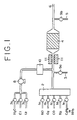
- Fig. 1 is a schematic diagram illustrating an apparatus for experimenting a method for the removal of nitrogen oxides according to this invention.
- an exhaust gas containing NO x is brought into contact with a component manifesting an oxidizing activity in an oxidizing atmosphere so that NO, N 2 O, etc. which are generally present at high proportions in the NO x components of the exhaust gas are oxidized or activated into NO 2 .
- the NO 2 thus resulting from the oxidation or activation is then adsorbed on a component possessing an NO 2 adsorbing ability.
- a reducing substance instantaneously into the exhaust gas enveloping the NO x accumulated on the adsorbent component, the adsorbed NO x is reduced or decomposed to complete the removal of NO x . It is the catalyst contemplated by this invention that discharges the function of reducing or decomposing the NO x .
- the reducing substances which are effectively usable in this invention include hydrocarbons, alcohols, urea and other similar organic substances, and ammonia and other similar inorganic substances, for example.
- the hydrocarbons may be saturated, unsaturated, linear, or branched hydrocarbons. They may be in a gaseous or liquid state at normal room temperature.
- the hydrocarbons which assume a gaseous state at normal room temperature are hydrocarbons having a carbon chain of C 1 to C 4 and those which assume a liquid state at normal room temperature are hydrocarbons having a carbon chain of C 5 to C 20 .
- such mixtures of hydrocarbons as gasoline, kerosene, and gas oil may be used.
- the aforementioned alcohols may be saturated, unsaturated, linear, or branched alcohols. They have a carbon chain of C 1 to C 6 . They may be dihydric or trihydric alcohols besides monohydric alcohols.
- the inorganic substances may be hydrogen and carbon monoxides besides ammonia.
- the amount of the reducing substance to be introduced into the exhaust gas is preferable to be in the range of 1 to 10 mols, preferably 1 to 5 mols, as reducing substance per mol (as NO) of the nitrogen oxides adsorbed on the catalyst. This amount is computed based on one molecule of the reducing substance when the reducing substance is an inorganic substance or on one carbon atom thereof when the reducing substance is an organic substance.
- This reducing substance generally is desired to be introduced in a gaseous state onto the catalyst. If the reducing substance is in a liquid state, however, it may be directly introduced in a sprayed state onto the catalyst with the aid of a nozzle, for example.
- the amount of the reducing substance to be introduced is less than 1 mol on the molar ratio defined above, the effect of the invention is not fully manifested. Conversely, if this amount exceeds 10 mols, the excess supply produces an unaltered portion of the reducing substance and poses a problem of disposal of the unaltered reducing substance, although the effect of the invention itself is infallibly manifested.
- the upper limit imposed on the introduction of the reducing agent may shift within some extent, since the reducing agent treating activity of the catalyst is also concerned with the disposal.
- the aforementioned magnitude is expressed on the basis of the molar ratio of the reducing substance when the reducing substance is an inorganic substance, it is expressed on the basis of the number of carbon atoms of the reducing substance when the reducing substance is an organic substance.
- the magnitude expressed as 2 mols of ammonia is adopted.
- the determination of the amount of the adsorbed nitrogen oxides may be attained, for example, by carrying out a preparatory experiment as described below. To be specific, this amount can be determined either directly in a given internal combustion engine operated under the conditions for working the method of this invention or indirectly in a desk-top apparatus adapted to simulate the temperature, composition, flow volume, etc. of the exhaust gas emanating from the internal combustion engine. Now, the procedure for the determination is shown below. First, in an exhaust gas pipe having nitrogen oxide analyzing meters disposed one each in front of and behind the prospective site for a catalyst bed, a catalyst conforming to this invention is packed in a prescribed amount to form the catalyst bed.
- a mixed gas of oxygen and nitrogen set at the same temperature and flow volume as those of a given exhaust gas under the working conditions of the catalyst is passed through the apparatus until this apparatus is fully stabilized. Thereafter, a gas containing nitrogen oxides at a concentration under the working conditions of the catalyst is introduced instead of the mixed gas into the catalyst bed.
- the nitrogen oxide concentrations are measured continuously with the analyzing meters until the scale reading of the analyzing meter disposed behind the catalyst bed ceases to vary. Each momentary differences between the nitrogen oxide concentrations before and after the catalyst bed are integrated and the integrated amount is recorded as the amount of nitrogen oxides adsorbed on the catalyst.
- the catalyst possibly has an ability to decompose nitrogen oxides during the measurement of the amount of nitrogen oxides to be adsorbed thereon. If the catalyst in use happens to possess this ability, the determination of the amount of adsorption cannot be based on the concentration of nitrogen oxides found in front of the catalyst bed. In this case, therefore, the amount of adsorption is computed, though in the same manner as described above, on the basis of the constant concentration of nitrogen oxides found behind the catalyst bed during the measurement of the amount of adsorption in the place of the concentration found in front of the catalyst bed.
- the amount of the reducing agent to be introduced may be suitably selected in due consideration of the flow volume and flow rate of the exhaust gas, the concentration of the nitrogen oxides in the exhaust gas, and the capacity of the catalyst for adsorbing nitrogen oxides. It is preferable to introduce the reducing agent to the catalyst bed before the catalyst has adsorbed nitrogen oxides to saturation.
- This introduction before the saturation of adsorption is attained by preparatorily computing the amount of nitrogen oxides in the exhaust gas per unit time based on the flow volume and flow rate of the exhaust gas and the concentration of nitrogen oxides therein, estimating the maximum length of time within which the amount of nitrogen oxides adsorbed on the catalyst does not reach the level of saturation, and continuing the introduction of the reducing agent until the time expires.
- the adsorption prior to reaching this state of saturation is preferable to be in the range of 5% to 90%, preferably 15% to 80%, of the saturated amount of adsorption. More preferably, it is in the range of 15% to 48%. If the amount of adsorption is less than 5%, the frequency of introducing the reducing agent must be increased possibly to the extent of jeopardizing the operating conditions of the apparatus. Conversely, if this amount exceeds 90%, on account of the approximation thereof to the saturated amount of adsorption, the adsorption of nitrogen oxides does not easily proceed and the amount of nitrogen oxides suffered to pass through the catalyst is consequently increased so much as to diminish the effect of this invention.
- the reducing agent depending on the quality thereof, has the possibility of being oxidized with the oxygen in the air and consequently prevented from manifesting an effect commensurate with the amount of its introduction.
- the deficiency is preferable to be compensated by preparatorily measuring the susceptibility of the reducing agent to the oxidation under the working conditions thereof as by use of an inert carrier and increasing the amount of the reducing agent being introduced proportionately to the degree of the susceptibility found as above.
- the reducing substance may be introduced at any time when the result of actual measurement as mentioned above reaches an appropriate level, with an amount correlative to the level.
- the reducing substance can be introduced with a prescribed time and amount schedule determined by repiating the former procedure suitable times, averaging the results of the measurements, and deciding the amount of the reducing substance correlative to the average.
- the reducing agent for use in this invention is introduced at intervals in the range of 7 seconds to 60 minutes, preferably in the range of 10 seconds to 20 minutes. If the intervals are less than 10 seconds, the frequency of introduction will be so high as to force a sacrifice of efficiency or economy. Conversely, if they exceed 60 minutes, the capacity of the catalyst of this invention for adsorption of NO x will be surpassed possibly to the extent of bringing about an adverse effect on the purification of the exhaust gas by the removal of NO x .
- the duration of this introduction is in the range of 0.1 to 20 seconds, preferably 1 to 10 seconds. If this duration is less than 0.1 second, thorough removal of the adsorbed NO x will not be possibly obtained. If it exceeds 20 seconds, the disadvantage arises that the reducing substance will possibly fail to operate effectively.
- intervals of the introduction and the duration of the introduction of the reducing substance which are specified above as preferable for this invention are variable to a certain extent due to the kind of the catalyst to be used. They may be suitably varied, therefore, within the ranges mentioned above.
- the NO x adsorbed on the catalyst in consequence of oxidation or activation is concentrated in an activated state on the catalyst as compared with the conventional method and, therefore, can be reduced by the catalyst with high selectivity unlike the method which comprises continuous introduction of the reducing agent.
- the method of this invention affords a saving in the total amount of the reducing agent to be introduced at all.
- the continued introduction of the reducing agent has the possibility of barring the oxidation or adsorption of the NO x and rather degrading the efficiency of purification of the exhaust gas by the removal of NO x .
- the NO x accumulated therein can be removed by instantaneously decreasing the amount of air being aspirated or supplying the fuel in an excess amount thereby enabling the exhaust gas to form a reducing atmosphere.
- the removal of the NO x from the exhaust gas can be carried out continuously.
- the reducing substance is introduced under conditions such that the catalyst will adsorb NO x thereon while the exhaust gas is in the state of containing excess air and, during the conversion of the adsorbed NO x into less harmful substances, the oxygen concentration during the introduction of the reducing agent will be lowered to the extent of allowing the reaction of the accumulated nitrogen oxides with the reducing agent to proceed more readily than the oxidation of the reducing agent.
- the removal of the accumulated nitrogen oxides can be carried out more efficiently.
- the exhaust gas to which the method of this invention is applied is not particularly limited.
- the method is effective when the exhaust gas to be treated forms an atmosphere of excess oxygen containing NO x in the range of 1 to 5,000 ppm. It is more effective when the exhaust gas forms an atmosphere of excess oxygen containing NO x in the range of 100 to 3,000 ppm.
- the conventional method suffices when the exhaust gas to be treated does not form an oxidizing atmosphere. If the NO x content is less than 1 ppm, the adsorption side will be at a disadvantage from the stoichiometric standpoint of adsorption. If it exceeds 5,000 ppm, the disadvantage will arise that the introduction of the reducing substance must be frequently carried out.
- This invention does not require the presence of an oxidizing atmosphere throughout the entire period of the purification of the exhaust gas. It can be effectively utilized even where an oxidizing atmosphere and a reducing atmosphere are alternated repeatedly.
- This invention in principle is capable of accomplishing the removal of NO x from the exhaust gas under treatment without reference to the NO x concentration in the exhaust gas.
- the exhaust gas under treatment contains nitrogen oxides at a high concentration, the duration of introduction of the reducing agent or the duration of impartation of a reducing atmosphere to the exhaust gas must be shortened.
- the space velocity (S.V.) of the exhaust gas under treatment relative to the catalyst bed is preferable to be in the range of 1,000 to 300,000/hr, preferably 10,000 to 200,000/hr. If the space velocity exceeds 300,000/hr, the catalyst will manifest ample reactivity with difficulty.
- the catalyst Conversely, if it falls short of 1,000/hr, the catalyst will have to be increased in volume and, moreover, the diffusion in the flow path of gas will bring about the influence of nullifying the effect of intermittently introducing the reducing substance or imparting a reducing atmosphere to the exhaust gas.
- the catalyst to be used in this invention comprises (A) catalytically active components composed of (a) 0.1 to 30 g as metal per liter of the catalyst of at least one noble metal selected from the group consisting of platinum, palladium, rhodium, and ruthenium or a compound of the noble metal and (b) 1 to 80 g as metal per liter of the catalyst of at least one alkali or alkaline earth metal selected from the group consisting of lithium, potassium, sodium, rubidium, cesium, beryllium, magnesium, calcium, strontium, and barium or a compound of the metal and (B) a refractory inorganic oxide and optionally further comprises as another catalycally active component 0.1 to 50 g per liter of the catalyst of at least one heavy metal selected from the group consisting of manganese, copper, cobalt, molybdenum, tungsten, and vanadium or a compound of the heavy metal.
- A catalytically active components composed of (a) 0.1 to 30 g
- such noble metals as platinum, palladium, rhodium, and ruthenium, particularly platinum and/or palladium, are effective in oxidizing NO x in an oxidizing atmosphere.
- These noble metals function to reduce and decompose NO x in the presence of a reducing substance or in a reducing atmosphere besides functioning to oxide NO x in an oxidizing atmosphere.
- the oxidation or activation of NO x in an oxidizing atmosphere and the removal of the adsorbed NO x , particularly NO 2 due to the intermittent introduction of a reducing substance or in a reducing atmosphere can be carried out with high efficiency.
- the amount of such a noble metal to be used is in the range of 0.1 to 30 g, preferably 0.5 to 5 g, as metal per liter of the catalyst. If this amount is less than 0.1 g, the oxidation of NO x will not easily proceed and the amount of NO x to be adsorbed will be unduly small and the reduction and removal of the adsorbed NO x will not be amply effected. Conversely, if it exceeds 30 g, the excess noble metal will produce no proportionate addition to the effect of noble metal and will increase the cost of material possibly to the extent of impairing the economy of the operation.
- alkali metals such as lithium, sodium, potassium, rubidium, and cesium or compounds thereof and/or alkaline earth metals such as magnesium, calcium, strontium, and barium or compounds thereof, particularly the compounds of alkali metals, are effectively used.
- the amount of this component to be used is in the range of 1 to 80 g, preferably 5 to 50 g, as metal per liter of the catalyst. If this amount is less than 1 g, the component acquires no sufficient capacity for adsorption of NO x and, therefore, manifests an unduly low capacity for treatment of NO x .
- the amount of the alkali metal mentioned above will be indicated as reduced to metal unless otherwise specified.
- the purification of the exhaust gas by the removal of NO x can be carried out with greater efficiency when at least one metal selected from the group consisting of manganese, copper, cobalt, molybdenum, tungsten, and vanadium or a compound of the metal is used as another catalytically active component in addition to the components mentioned above.
- This catalytically active component is thought to play the part of promoting the oxidation and adsorption of NO x in an oxidizing atmosphere and/or promoting the reduction and decomposition of the adsorbed NO x in the presence of a reducing agent or in an oxidizing atmosphere.
- the amount of this component to be used is in the range of 0.1 to 50 g, preferably 1 to 20 g, per liter of the catalyst. If this amount is less than 0.1 g, neither the adsorption of nitrogen oxides nor the reduction of the adsorbed NO x will be amply promoted. Conversely, if the amount exceeds 50 g, the excess component will not bring about any proportionate addition to the capacity for NO x adsorption or the capacity for NO x reduction.
- any of the inorganic oxides which are generally used as carriers for catalysts can be adopted.
- these inorganic oxides ⁇ -alumina, ⁇ -, ⁇ -, ⁇ -, or ⁇ -activated alumina, titania, zirconia, ceria, lanthana, or silica, mixtures thereof, and complex oxides may be cited.
- the amount of the refractory inorganic oxide to be used is in the range of 50 to 400 g, preferably 100 to 300 g, per liter of the catalyst. The weight of the oxide will be computed based on stable oxide unless otherwise specified.
- the refractory inorganic oxide is generally in a powdery form.
- the Brunauer-Emmett-Teller (hereinafter referred to as "BET”) surface area of the oxide is in the range of 10 to 400 m 2 /g, preferably 50 to 300 m 2 /g.
- the oxidizing component, the adsorbing component, and the auxiliary component of the catalyst are preferable to be carried in a homogeneously mixed state on the refractory inorganic oxide instead of being locally distributed.
- the mixture comprising the catalytically active components and the refractory inorganic oxide, in the actual treatment of the exhaust gas is used in the unmodified powdery form, in the molded form thereof such as pellets or honeycombs, or in the coating form to a three-dimensional structure base.
- the form using the three-dimensional structure for coating proves particularly preferable.
- pellets and honeycomb carriers may be cited.
- monolithically molded honeycomb structures prove particularly preferable.
- monolithic honeycomb carriers, metal honeycomb carriers, and plug honeycomb carriers may be cited.
- the monolithic carriers may be any of those which are generally called the ceramic honeycomb carriers.
- the honeycomb carriers which are made of such materials as cordierite, mullite, ⁇ -alumina, zirconia, titania, titanium phosphate, aluminum titanate, bellite, spodumene, aluminosilicate, and magnesium silicate prove preferable.
- the honeycomb carriers made of cordierite prove especially preferable.
- the monolithically molded structures which are made of such metals resistant to oxidation and proof against heat as stainless steel and Fe-Cr-Al alloy are also usable.
- These monolithic carriers are produced by the extrusion molding technique or the process of tightly rolling a sheetlike material.
- the openings (cells) formed therein for passage of a gas under treatment may be in a hexagonal, tetragonal, or triangular cross section or in a corrugated cross section.
- a cell density (number of cells/unit cross section) which falls in the range of 100 to 600 cells/square inch, preferably 200 to 500 cells/square inch, suffices for effective use of the monolithic carriers.
- the amount of the mixture of the catalytically active components and the refractory inorganic oxide to be deposited on the honeycomb structure is in the range of 50 to 500 g, preferably 100 to 300 g, per liter of the catalyst. If this amount is less than 50 g, the mixture fails to manifest ample activity because of an unduly small amount thereof. If the amount exceeds 500 g, the disadvantage arises that the exhaust gas under treatment will suffer as from loss of pressure.
- the amount of the catalytically active components to be used per liter of the catalyst is computed based on the volume of the molded structure itself when those components are molded by themselves or based on a three-dimensional structure when the components are deposited on the three-dimensional structure base.
- the examples are (a) a method for obtaining a finished catalyst by impregnating a refractory inorganic oxide with a mixed solution of catalytically active components, drying the resultant impregnated composite, optionally calcining the dry composite thereby obtaining a powder, wet pulverizing the powder together with water added thereto and consequently forming a slurry, applying the slurry to a honeycomb structure and allowing the applied coat of slurry to dry, and optionally calcining the coated honeycomb structure, (b) a method for obtaining a finished catalyst by wet pulverizing a refractory inorganic oxide together with water added thereto thereby forming a slurry, applying the slurry to a honeycomb structure and drying the applied coat of slurry, optionally calc
- the catalyst mentioned above may be used in combination with an oxidizing catalyst or a three-way catalyst.
- the catalyst described above may be disposed in the leading stage and the oxidizing catalyst or three-way catalyst in the trailing stage relative to the inlet for the exhaust gas.
- the three-way catalyst is used for the purpose of enhancing the stoichiometric conversion of NO x with the oxidizing catalyst.
- the ratio of purification of the exhaust gas is low as when an automobile is being started.
- the low temperature is undesirable because it causes particularly the ratios of removal of CO and HC to be conspicuously increased.
- the ratio of conversion of HC can be enhanced by preparatorily elevating the temperature of the exhaust gas.
- the purification of the exhaust gas may be carried out with a three-way catalyst or an oxidizing catalyst installed as a warm-up catalyst.
- the removal of nitrogen oxides from the exhaust gas may be effected by a method of disposing the three-way catalyst or oxidizing catalyst on the upstream side of the flow of the exhaust gas, then the catalyst set forth in claim 1 next thereto, and the three-way catalyst or oxidizing catalyst farther on the downstream side.
- the oxidizing catalyst has no particular restriction. It is only required to be capable of oxidizing hydrocarbons and carbon monoxide.
- the catalytic components which are effectively usable in the oxidizing catalyst include noble metals such as platinum and/or palladium and refractory inorganic oxides such as alumina, titania, and silica, for example.
- noble metals such as platinum and/or palladium and refractory inorganic oxides such as alumina, titania, and silica, for example.
- One or more members selected from among rare earth oxides such as lanthanum oxide (La 2 O 3 ) and from among metals such as iron, cobalt and nickel may be additionally used.
- the amount of the noble metal to be preferable is desired to be in the range of 0.1 to 5 g per liter of the catalyst.
- the amount of the refractory inorganic oxide to be carried is preferable to be in the range of 10 to 300 g per liter of the catalyst.
- the amount thereof is preferable to be within the range of >0 to 150 g per liter of the catalyst.
- the catalyst will acquire only an unduly low capacity for the purification. If it exceeds 5 g per liter, the excess supply of the noble metal will bring about no proportionate addition to the effect. If the amount of the refractory inorganic oxide to be added is less than 10 g per liter, the ability to disperse the noble metal will be degraded intolerably. If it exceeds 300 g per liter, the excess supply of the inorganic oxide will bring about the adverse effect of clogging a honeycomb being used as a carrier for the refractory inorganic oxide.
- the oxide of a rare earth element is added for the purpose of improving the thermal stability of the refractory inorganic oxide.
- the excess supply of the oxide will bring about the adverse effect of intolerably degrading the strength with which the catalytic component is carried.
- the catalyst comprising at least one metal selected from the group consisting of platinum and palladium, at least one metal selected from the group consisting of potassium, sodium, rubidium, and cesium, and a refractory inorganic oxide is disposed on the upstream side of the flow of the exhaust gas and then an oxidizing catalyst is disposed next thereto, the contents of CO, HC, etc. in the exhaust gas can be further lowered than when no oxidizing catalyst is used.
- a) palladium, (b) platinum and rhodium, (c) palladium and rhodium, or (d) platinum, palladium, and rhodium as noble metal component(s), a refractory inorganic oxide such as alumina, titania, or silica, and ceria are essential catalytic components for the three-way catalyst.
- This three-way catalyst may additionally incorporate therein zirconia and/or the oxide of a rare earth element other than cerium such as, for example, lanthanum oxide (La 2 O 3 ).
- the three-way catalyst is generally prepared by having the catalytic components deposited on a honeycomb which is generally used as a carrier for a catalyst.
- the amount of the noble metal to be deposited is preferable to be in the range of 0.1 to 5 g, the amount of such a refractory inorganic oxide as alumina, titania, or silica to be in the range of 10 to 300 g, the amount of ceria (Ce 2 O 3 ) to be in the range of 10 to 150 g, and the amount of the oxide of a rare earth element other than cerium to be in the range of 0 to 50 g respectively per liter of the catalyst. If the amount of the noble metal is less than 0.1 g per liter, the catalyst will acquire an unduly low capacity for the purification.
- the excess supply of the noble metal will bring about no discernible addition to the effect of noble metal. If the amount of the refractory inorganic oxide is less than 10 g per liter, the insufficient supply of this oxide will produce the adverse effect of impairing the ability thereof to disperse the noble metal, for example. If this amount exceeds 300 g per liter, the excess supply of this oxide will bring about the adverse effect of clogging a honeycomb being used as a carrier for the refractory inorganic oxide. If the amount of ceria is less than 10 g per liter, the effect of ceria manifested in storing and discharging oxygen will not be fully manifested throughout the entire volume of the catalyst.
- the excess supply of ceria will produce the adverse effect of degrading the strength with which the catalytic components are carried.
- the addition of the oxide of a rare earth element other than cerium is intended to improve the thermal stability of the refractory inorganic oxide. If the amount of this oxide to be added exceeds 50 g per liter, the excess supply of the oxide will produce the adverse effect of degrading the strength with which the catalytic components are carried because ceria is deposited to some extent on the three-way catalyst.
- the three-way catalyst removes NO x in a stoichiometric condition. It fails to effect the removal of NO x in a lean condition.
- This invention allows the removal of NO x to proceed in a stoichiometric condition to a greater extent when a catalyst comprising at least one metal selected from the group consisting of platinum and palladium, at least one metal selected from the group consisting of potassium, sodium, rubidium, and cesium, and a refractory inorganic oxide is disposed on the upstream side of the flow of the exhaust gas and a three-way catalyst is disposed next thereto than when no three-way catalyst is disposed at all.
- a powder was obtained by mixing 200 g of activated alumina having a BET surface area of 100 m 2 /g with an aqueous dinitrodiammineplatinum solution containing 3 g of platinum, drying the resultant mixture at 120°C for 2 hours, and calcining the dry mixture at 500°C for 2 hours. This powder was wet pulverized in a ball mill to obtain an aqueous slurry.
- a cordierite honeycomb carrier (the product of Nippon Glass Co., Ltd.: containing 400 gas flow cells per square inch of cross section and measuring 33 mm in diameter, 76 mm in length, and 65 ml in volume) was dipped in the aqueous slurry, then removed therefrom, and blown with compressed air to expel excess slurry. Then, the carrier coated with the slurry was dried at 120°C for 2 hours and calcined at 500°C for 2 hours to obtain a honeycomb carrier coated with a platinum-carrying alumina powder.
- the honeycomb carrier was dipped in an aqueous solution containing sodium nitrate at a concentration of 4.3 mols/liter, removed therefrom, blown with compressed air to expel excess aqueous solution therefrom, dried at 120°C, and calcined at 500°C to obtain a finished catalyst (1).
- This catalyst was found to have deposited on the carrier 3 g of platinum, 10 g of sodium (as metal), and 200 g of activated alumina per liter of the carrier.
- a finished catalyst (2) was obtained by following the procedure of Referential Example 1 while using an aqueous palladium nitrate solution containing 3 g of palladium in the place of the aqueous dinitrodiammineplatinum solution containing 3 g of platinum. This catalyst was found to have deposited on the carrier 3 g of palladium, 10 g of sodium, and 200 g of activated alumina per liter of the carrier.
- a finished catalyst (3) was obtained by following the procedure of Referential Example 1 while using an aqueous rhodium nitrate solution containing 3 g of rhodium in the place of the aqueous dinitrodiammineplatinum solution containing 3 g of platinum. This catalyst was found to have deposited on the carrier 3 g of rhodium, 10 g of sodium, and 200 g of activated alumina per liter of the carrier.
- a finished catalyst (4) was obtained by following the procedure of Referential Example 1 while using an aqueous ruthenium chloride solution containing 3 g of ruthenium in the place of the aqueous dinitrodiammineplatinum solution containing 3 g of platinum. This catalyst was found to have deposited on the carrier 3 g of ruthenium, 10 g of sodium, and 200 g of activated alumina per liter of the carrier.
- a finished catalyst (5) was obtained by following the procedure of Referential Example 1 while using an aqueous solution containing lithium nitrate at a concentration of 14.4 mols/liter in the place of the aqueous solution containing sodium nitrate at a concentration of 4.3 mols/liter. This catalyst was found to have deposited on the carrier 3 g of platinum, 10 g of lithium, and 200 g of activated alumina per liter of the carrier.
- a finished catalyst (6) was obtained by following the procedure of Referential Example 1 while using an aqueous solution containing potassium nitrate at a concentration of 2.6 mols/liter in the place of the aqueous solution containing sodium nitrate at a concentration of 4.3 mols/liter.
- This catalyst was found to have deposited on the carrier 3 g of platinum, 10 g of potassium, and 200 g of activated alumina per liter of the carrier.
- a finished catalyst (7) was obtained by following the procedure of Referential Example 1 while using an aqueous solution containing rubidium nitrate at a concentration of 1.2 mols/liter in the place of the aqueous solution containing sodium nitrate at a concentration of 4.3 mols/liter.
- This catalyst was found to have deposited on the carrier 3 g of platinum, 10 g of rubidium, and 200 g of activated alumina per liter of the carrier
- a finished catalyst (8) was obtained by following the procedure of Referential Example 1 while using an aqueous solution containing cesium nitrate at a concentration of 0.8 mol/liter in the place of the aqueous solution containing sodium nitrate at a concentration of 4.3 mols/liter. This catalyst was found to have deposited on the carrier 3 g of platinum, 10 g of cesium, and 200 g of activated alumina per liter of the carrier.
- a finished catalyst (9) was obtained by following the procedure of Referential Example 1 while using an aqueous solution containing beryllium nitrate at a concentration of 11.1 mols/liter in the place of the aqueous solution containing sodium nitrate at a concentration of 4.3 mols/liter.
- This catalyst was found to have deposited on the carrier 3 g of platinum, 10 g of beryllium, and 200 g of activated alumina per liter of the carrier.
- a finished catalyst (10) was obtained by following the procedure of Referential Example 1 while using an aqueous solution containing magnesium nitrate at a concentration of 8.2 mols/liter in the place of the aqueous solution containing sodium nitrate at a concentration of 4.3 mols/liter.
- This catalyst was found to have deposited on the carrier 3 g of platinum, 20 g of magnesium, and 200 g of activated alumina per liter of the carrier.
- a finished catalyst (11) was obtained by following the procedure of Referential Example 1 while using an aqueous solution containing calcium nitrate at a concentration of 5.0 mols/liter in the place of the aqueous solution containing sodium nitrate at a concentration of 4.3 mols/liter. This catalyst was found to have deposited on the carrier 3 g of platinum, 20 g of calcium, and 200 g of activated alumina per liter of the carrier.
- a finished catalyst (12) was obtained by following the procedure of Referential Example 1 while using an aqueous solution containing strontium nitrate at a concentration of 2.3 mols/liter in the place of the aqueous solution containing sodium nitrate at a concentration of 4.3 mols/liter. This catalyst was found to have deposited on the carrier 3 g of platinum, 20 g of strontium, and 200 g of activated alumina per liter of the carrier.
- a finished catalyst (13) was obtained by following the procedure of Referential Example 1 while using an aqueous solution containing barium acetate at a concentration of 1.5 mols/liter in the place of the aqueous solution containing sodium nitrate at a concentration of 4.3 mols/liter.
- This catalyst was found to have deposited on the carrier 3 g of platinum, 20 g of barium, and 200 g of activated alumina per liter of the carrier.
- a finished catalyst (14) was obtained by following the procedure of Referential Example 1 while using a mixed aqueous solution containing dinitrodiammineplatinum incorporating 3 g of platinum therein and copper nitrate incorporating 2 g of copper therein in the place of the aqueous dinitrodiammineplatinum solution containing 3 g of platinum.
- This catalyst was found to have deposited on the carrier 3 g of platinum, 2 g of copper, 10 g of sodium, and 200 g of activated alumina per liter of the carrier.
- a finished catalyst (15) was obtained by following the procedure of Referential Example 1 while using a mixed aqueous solution containing dinitrodiammineplatinum incorporating 3 g of platinum therein and cobalt nitrate incorporating 2 g of cobalt therein in the place of the aqueous dinitrodiammineplatinum solution containing 3 g of platinum.
- This catalyst was found to have deposited on the carrier 3 g of platinum, 2 g of cobalt, 10 g of sodium, and 200 g of activated alumina per liter of the carrier.
- a finished catalyst (16) was obtained by following the procedure of Referential Example 1 while using a mixed aqueous solution containing dinitrodiammineplatinum incorporating 3 g of platinum therein and manganese nitrate incorporating 2 g of manganese therein in the place of the aqueous dinitrodiammineplatinum solution containing 3 g of platinum.
- This catalyst was found to have deposited on the carrier 3 g of platinum, 2 g of manganese, 10 g of sodium, and 200 g of activated alumina per liter of the carrier.
- a finished catalyst (17) was obtained by preparing a catalyst (A) in the same manner as in Referential Example 1, dipping this catalyst in an aqueous solution containing ammonium molybdate at a concentration of 0.5 mol/liter, removing the catalyst therefrom, blowing the wet catalyst with compressed air to expel excess aqueous solution therefrom, drying the catalyst at 120°C, and calcining the dry catalyst at 500°C.
- This finished catalyst was found to have deposited on the carrier 3 g of platinum, 10 g of sodium, 5 g of molybdenum, and 200 g of activated alumina per liter of the carrier.
- a finished catalyst (18) was obtained by preparing a catalyst (A) in the same manner as in Referential Example 1, dipping this catalyst in an aqueous solution containing ammonium tungstate at a concentration of 0.3 mol/liter, removing the catalyst therefrom, blowing the wet catalyst with compressed air to expel excess aqueous solution therefrom, drying the catalyst at 120°C, and calcining the dry catalyst at 500°C.
- This finished catalyst was found to have deposited on the carrier 3 g of platinum, 10 g of sodium, 5 g of tungsten, and 200 g of activated alumina per liter of the carrier.
- a finished catalyst (19) was obtained by preparing a catalyst (A) in the same manner as in Referential Example 1, dipping this catalyst in an aqueous solution containing vanadyl oxalate at a concentration of 1.0 mol/liter, removing the catalyst therefrom, blowing the wet catalyst with compressed air to expel excess aqueous solution therefrom, drying the catalyst at 120°C, and calcining the dry catalyst at 500°C.
- This finished catalyst was found to have deposited on the carrier 3 g of platinum, 10 g of sodium, 5 g of vanadium, and 200 g of activated alumina per liter of the carrier.
- a powder was obtained by mixing 100 g of the same activated alumina as used in Referential Example 1 with a mixed solution of an aqueous dinitrodiammineplatinum solution containing 2 g of platinum and an aqueous rhodium nitrate solution containing 0.4 g of rhodium, drying the resultant mixture at 120°C for two hours, and calcining the dry mixture at 500°C for two hours.
- This powder and 50 g of cerium oxide were wet pulverized together in a ball mill to obtain an aqueous slurry.
- the same honeycomb carrier as used in Referential Example 1 was dipped in the aqueous slurry, removed therefrom, and blown with compressed air to expel excess aqueous slurry.
- This catalyst was found to have deposited on the carrier 2 g of platinum, 0.4 g of rhodium, 50 g of cerium oxide, and 100 g of activated alumina per liter of the carrier.
- Zeolite, grade ZSM-5 was prepared in accordance with the information reported in literature (Rapid Crystallization Method, Proceedings 8th International Congress on Catalysis, Berin, 1984, Vol. 3, P 569). By the X-ray analysis, the zeolite thus obtained was identified as the product of grade ZSM-5. To the mixture obtained by stirring 1.5 kg of this zeolite, grade ZSM-5, and 6 liters of purified water added thereto at 98°C for two hours, an aqueous solution containing copper ammine complex at a concentration of 0.2 mol/liter was slowly added dropwise at 80°C. After the addition was completed, the resultant mixture was stirred continuously at 80°C for 12 hours.
- a finished catalyst (21) was obtained by following the procedure of Referential Example 1 while using the aqueous slurry instead. This catalyst was found to have deposited on the carrier 120 g of the zeolite, grade ZSM-5, and 6.9 g of copper per liter of the carrier.
- a finished catalyst (22) was obtained by following the procedure of Referential Example 6 while using 0.05 g of platinum in the place of the aqueous dinitrodiammineplatnum solution containing 3 g of platinum. This catalyst was found to have deposited on the carrier 0.05 g of platinum, 10 g of potassium, and 200 g of activated alumina per liter of the carrier.
- a finished catalyst (23) was obtained by following the procedure of Referential Example 6 while using 0.2 g of platinum in the place of the aqueous dinitrodiammineplatnum solution containing 3 g of platinum. This catalyst was found to have deposited on the carrier 0.2 g of platinum, 10 g of potassium, and 200 g of activated alumina per liter of the carrier.
- a finished catalyst (24) was obtained by following the procedure of Referential Example 6 while using 25 g of platinum in the place of the aqueous dinitrodiammineplatnum solution containing 3 g of platinum. This catalyst was found to have deposited on the carrier 25 g of platinum, 10 g of potassium, and 200 g of activated alumina per liter of the carrier.
- a finished catalyst (25) was obtained by following the procedure of Referential Example 6 while using 40 g of platinum in the place of the aqueous dinitrodiammineplatnum solution containing 3 g of platinum. This catalyst was found to have deposited on the carrier 40 g of platinum, 10 g of potassium, and 200 g of activated alumina per liter of the carrier.
- a finished catalyst (26) was obtained by following the procedure of Referential Example 6 while using a mixed solution of an aqueous dinitrodiammineplatinum solution containing 3 g of platinum and an aqueous palladium nitrate solution containing 2 g of palladium in the place of the aqueous dinitrodiammineplatnum solution containing 3 g of platinum.
- This catalyst was found to have deposited on the carrier 3 g of platinum, 2 g of palladium, 10 g of potassium, and 200 g of activated alumina per liter of the carrier.
- a finished catalyst (27) was obtained by following the procedure of Referential Example 6 while using a mixed solution of an aqueous dinitrodiammineplatinum solution containing 3 g of platinum and an aqueous rhodium nitrate solution containing 0.3 g of rhodium in the place of the aqueous dinitrodiammineplatnum solution containing 3 g of platinum.
- This catalyst was found to have deposited on the carrier 3 g of platinum, 0.3 g of rhodium, 10 g of potassium, and 200 g of activated alumina per liter of the carrier.
- a finished catalyst (28) was obtained by following the procedure of Referential Example 6 while using a mixed solution of an aqueous dinitrodiammineplatinum solution containing 3 g of platinum and an aqueous ruthenium nitrate solution containing 0.3 g of ruthenium in the place of the aqueous dinitrodiammineplatnum solution containing 3 g of platinum.
- This catalyst was found to have deposited on the carrier 3 g of platinum, 0.3 g of ruthenium, 10 g of potassium, and 200 g of activated alumina per liter of the carrier.
- a finished catalyst (29) was obtained by following the procedure of Referential Example 6 while using a mixed solution of an aqueous palladium nitrate solution containing 5 g of palladium and an aqueous rhodium nitrate solution containing 0.3. g of rhodium in the place of the aqueous dinitrodiammineplatnum solution containing 3 g of platinum.
- This catalyst was found to have deposited on the carrier 5 g of palladium, 0.3 g of rhodium, 10 g of potassium, and 200 g of activated alumina per liter of the carrier.
- a finished catalyst (30) was obtained by following the procedure of Referential Example 6 while using an aqueous solution containing potassium nitrate at a concentration of 0.13 mol/liter in the place of the aqueous solution containing potassium nitrate at a concentration of 2.6 mols/liter.
- This catalyst was found to have deposited on the carrier 3 g of platinum, 0.5 g of potassium, and 200 g of activated alumina per liter of the carrier.
- a finished catalyst (31) was obtained by following the procedure of Referential Example 6 while using an aqueous solution containing potassium nitrate at a concentration of 0.52 mol/liter in the place of the aqueous solution containing potassium nitrate at a concentration of 2.6 mols/liter.
- This catalyst was found to have deposited on the carrier 3 g of platinum, 2 g of potassium, and 200 g of activated alumina per liter of the carrier.
- a finished catalyst (32) was obtained by following the procedure of Referential Example 6 while using an aqueous solution containing potassium nitrate at a concentration of 18.2 mols/liter in the place of the aqueous solution containing potassium acetate at a concentration of 2.6 mols/liter.
- This catalyst was found to have deposited on the carrier 3 g of platinum, 70 g of potassium, and 200 g of activated alumina per liter of the carrier.
- a finished catalyst (33) was obtained by following the procedure of Referential Example 6 while using an aqueous solution containing potassium nitrate at a concentration of 23.4 mols/liter in the place of the aqueous solution containing potassium acetate at a concentration of 2.6 mols/liter.
- This catalyst was found to have deposited on the carrier 3 g of platinum, 90 g of potassium, and 200 g of activated alumina per liter of the carrier.
- a finished catalyst (34) was obtained by following the procedure of Referential Example 15 while using a mixed aqueous solution of cobalt nitrate containing 0.05 g of cobalt in the place of the aqueous solution of cobalt nitrate containing 2 g of cobalt.
- This catalyst was found to have deposited on the carrier 3 g of platinum, 0.05 g of cobalt, 10 g of sodium, and 200 g of activated alumina per liter of the carrier.
- a finished catalyst (35) was obtained by following the procedure of Referential Example 15 while using a mixed aqueous solution of cobalt nitrate containing 0.2 g of cobalt in the place of the aqueous solution of cobalt nitrate containing 2 g of cobalt.
- This catalyst was found to have deposited on the carrier 3 g of platinum, 0.2 g of cobalt, 10 g of sodium, and 200 g of activated alumina per liter of the carrier.
- a finished catalyst (36) was obtained by following the procedure of Referential Example 15 while using a mixed aqueous solution of cobalt nitrate containing 25 g of cobalt in the place of the aqueous solution of cobalt nitrate containing 2 g of cobalt.
- This catalyst was found to have deposited on the carrier 3 g of platinum, 25 g of cobalt, 10 g of sodium, and 200 g of activated alumina per liter of the carrier.
- a finished catalyst (37) was obtained by following the procedure of Referential Example 15 while using a mixed aqueous solution of cobalt nitrate containing 40 g of cobalt in the place of the aqueous solution of cobalt nitrate containing 2 g. of cobalt.
- This catalyst was found to have deposited on the carrier 3 g of platinum, 40 g of cobalt, 10 g of sodium, and 200 g of activated alumina per liter of the carrier.
- a powder was obtained by mixing 100 g of the same activated alumina as used in Referential Example 1 with an aqueous dinitrodiammineplatinum solution containing 1 g of platinum, drying the resultant mixture at 120°C for 2 hours, and calcining the dry mixture at 500°C for 2 hours.
- An aqueous slurry was obtained by wet pulverizing the powder, 2 g of lanthanum oxide, and 2 g of iron oxide together in a ball mill.
- a finished catalyst (38) was obtained by following the procedure of Referential Example 20 while using the aqueous slurry instead. This finished catalyst was found to have deposited on the carrier 1 g of platinum, 2 g of lanthanum oxide, 2 g of iron oxide, and 100 g of activated alumina per liter of the carrier.
- a sample catalyst was packed in a stainless steel pipe 34.5 mm in diameter and 300 mm in length.
- a reaction gas of the following composition was introduced into the stainless steel pipe at a spatial velocity of 20,000/hr.
- the sample catalyst was analyzed to determine the capacity thereof for adsorption of nitrogen oxides.
- an apparatus having chemical emission type nitrogen oxide analyzers (capable of determining the NO and NO 2 contents as the total NO x content) (omitted from illustration) connected one each via conduits 3 and 5 to the pipe at the points in front of and behind an enclosure for a catalyst bed 4 as illustrated in Fig. 1 was used.
- the enclosure for a catalyst bed 4 in the apparatus kept heated with an electric furnace 11 was filled with the sample catalyst.
- a reaction gas was formed by feeding 500 ppm of nitrogen monoxide (NO), 2.0% by volume of oxygen, 2,000 ppm of carbon monoxide, and the balance to make up 100% by volume of nitrogen respectively via regulating valves 1a, 1b, 1c, and 1d to a gas mixer 2.
- NO nitrogen monoxide
- a liquid supply pump 8 and an evaporator 10 water was advanced via a liquid supply valve 7a at a ratio calculated to give the reaction gas a water content of 10% by volume and introduced into the catalyst bed 4.
- Propylene (C 3 H 6 ) was fed for a duration of 10 seconds once per minute via a regulating valve 1e at a ratio calculated to give the reaction gas a propylene content of 3,000 ppm (as methane) and introduced into the reaction gas in the gas mixer 2.
- the reaction gas finally formed was supplied at a spatial velocity of 20,000 hr -1 to the catalyst bed 4, with the inlet temperature of the catalyst kept at 400°C with the electric furnace 11 to carry out Test 1.
- the exhaust gas emanating from the catalyst bed was discharged through a gas outlet 6.
- samples of the gas were extracted through the conduit 5 via a sampling valve 9b and introduced into the analyzer to determine the ratios of removal of NO x .
- the results are shown in Table 1.
- This invention pertains to a method for the removal of nitrogen oxides from an exhaust gas characterized by causing the exhaust gas in an oxidizing atmosphere to contact a catalyst comprising a refractory inorganic oxide and catalytically active components, the components comprising 0.1 to 30 g as metal per liter of the catalyst of at least one noble metal selected from the group consisting of platinum, palladium, rhodium, and ruthenium or a compound of the noble metal and 1 to 80 g as metal per liter of the catalyst of at least one metal selected from the group consisting of lithium, potassium, sodium, rubidium, cesium, beryllium, magnesium, calcium, strontium, and barium or a compound of the metal, thereby inducing the catalyst to adsorb thereon the nitrogen oxides in the exhaust gas and, subsequently introducing a reducing substance intermittently into the exhaust gas thereby purifying the exhaust gas by reducing the nitrogen oxides adsorbed on the catalyst.
- the method of this invention permits efficient disposal of NO x by use of a reducing agent only in a small amount without requiring any special device.
- the catalytic system contemplated by this invention when used in combination with an oxidizing catalyst and/or a three-way catalyst, produces the advantage of further exalting the efficiency of the removal of hydrocarbons and carbon monoxide.
Description
- This invention relates to purification of an industrial exhaust gas by removal of nitrogen oxides therefrom. More particularly, it relates to the purification of the industrial exhaust gas emanating as from a boiler, a power generation plant, an industrial plant, or an internal combustion engine like a gasoline or diesel engine by the removal of nitrogen oxides therefrom.
- In recent years, the exhaust gases such as are emanating from internal combustion engines of automobiles, boilers, or industrial plants contain noxious substances such as nitrogen oxides (hereinafter occasionally referred to collectively as "NOx") which form the cause for air pollution. Generally, the NOx are not easily reduced or decomposed in an oxidizing atmosphere (the atmosphere embracing the exhaust gas and having an oxygen supply more than necessary for complete combustion of the unburnt portion of the fuel entrained in the exhaust gas). As a result, the removal of the NOx from the exhaust gas is attained only with difficulty. Thus, the removal of NOx from a varying exhaust gas has been the subject of a scientific study in various fields.
- For the purification of the exhaust gas from automobiles, it has been heretofore customary to adopt the method of treating the exhaust gas with a three-way catalyst thereby simultaneously removing NOx, hydrocarbons (HC), and carbon monoxide (CO). By this method, the atmosphere of the exhaust gas to be treated is in the neighborhood of stoichiometry (which is the theoretical air-fuel ratio, namely the ratio of air required for complete combustion of the fuel). When the internal combustion engine is operated with the air introduced in an amount in excess of this theoretical air-fuel ratio, the oxygen is present at the site of treatment more than necessary for complete combustion of the unburnt portions such as of hydrocarbons and carbon monoxide in the exhaust gas. In the exhaust gas present in the oxidizing atmosphere of this kind, therefore, it is difficult to reduce, decompose, and remove the NOx.
- In respect to the diesel engines, boilers, etc., it is general to use a reducing agent such as ammonia, hydrogen, or carbon monoxide. This method, however, entails the problem of necessitating a special device for recovering and disposing of the unaltered portion of the reducing agent. It, therefore, cannot be effectively applied easily to a small NOx generating sources such as engines in automobiles or cogeneration systems in buildings. Particularly in the removal of NOx of a relatively low concentration, this method operates with notably low efficiency.
- Recently as a means for the removal of NOx, the method resorting to use of a NOx decomposing catalyst made of a copper ion-containing crystalline aluminosilicate has been proposed (as in JP-A-60-125,250, US-A-4,297,328, etc.). This method is depicted therein simply as being capable of decomposing nitrogen monoxide (NO) into nitrogen (N2) and oxygen (O2). It does not easily obtain effective removal of NOx from the exhaust gas which emanates under actual conditions. Further, it is known that aluminosilicates are generally so deficient in resistance to heat as to offer no infallible use at elevated temperatures.
- JP-A-63-100,919 has a mention to the effect that when the exhaust gas is treated with a copper-containing catalyst under an oxidizing atmosphere in the presence of a hydrocarbon, the reaction of the exhaust gas proceeds preferentially with the hydrocarbon and, therefore, the removal of NOx. is obtained with high efficiency. It is remarked that the hydrocarbon to be used in this method may be either the hydrocarbon which is contained per se in the exhaust gas or the hydrocarbon which is added as occasion demands from an external source. Specifically, this method is carried out by first bringing the exhaust gas into contact with the copper-containing catalyst thereby removing NOx therefrom and then causing the residual exhaust gas to contact an oxidizing catalyst thereby removing hydrocarbons, carbon monoxide, etc. If the exhaust gas to be treated by this method happens to have an unduly low hydrocarbon content, the method will necessitate continuous introduction of the hydrocarbon into the exhaust gas. Further, in the oxidizing atmosphere, since the combustion of HC proceeds preferentially over the reaction of the hydrocarbon with NOx, thorough removal of the NOx from the exhaust gas requires the hydrocarbon to be introduced in a large amount.
- JP-A-04-250,822 discloses a method for purifying such an NOx-containing air as generated in a tunnel by passing the air through an absorption tower thereby effecting absorption and concentration of the NOx and then introducing the separated NOx into a reaction tower packed with an NOx reducing catalyst. This method requires two devices, the one for absorption and the other for reduction of the NOx.
- EP-A-0.507.590 discloses a method for the removal of nitrogen oxides from an exhaust gas with a catalyst having the same composition as set out in present claim 1 while fluctuating the air-fuel (A/F) ratio to +/- 1.0 at 1 Hz over a range between 15.1 and 14.1.
- A method which is capable of efficiently decomposing and removing the NOx from the exhaust gas and enabling a catalyst to manifest excellent durability to tolerate high temperatures and ideal packability in a reactor remains yet to be developed. Such is the existing state of the art.
- An object of this invention, therefore, is to provide a method which is capable of efficiently removing NOx from exhaust gas in an oxidizing atmosphere while precluding the drawbacks mentioned above.
- The object described above is accomplished by a method for the removal of nitrogen oxides from an exhaust gas characterized by causing the exhaust gas in an oxidizing atmosphere to contact a catalyst comprising a refractory inorganic oxide and catalytically active components, the components comprising 0.1 to 30 g as metal per liter of the catalyst of at least one noble metal selected from the group consisting of platinum, palladium, rhodium, and ruthenium or a compound of the noble metal and 1 to 80 g as metal per liter of the catalyst of at least one metal selected from the group consisting of lithium, potassium, sodium, rubidium, cesium, beryllium, magnesium, calcium, strontium, and barium or a compound of the metal, thereby inducing the catalyst to adsorb thereon the nitrogen oxides in the exhaust gas and, subsequently introducing a reducing substance intermittently into the exhaust gas thereby purifying the exhaust gas by reducing the nitrogen oxides adsorbed on the catalyst.
- This invention further contemplates the method mentioned above, wherein as the component at least one heavy metal selected from the group consisting of manganese, copper, cobalt, molybdenum, tungsten, and vanadium or a compound of the heavy metal is further contained in an amount in the range of 0.1 to 50 g per liter of the catalyst. This invention also contemplates the method mentioned above, wherein the catalyst has a capacity for adsorbing the nitrogen oxides to saturation in the range of 6 to 30 m.mols per liter of the catalyst. This invention contemplates the method mentioned above, wherein the introduction of the reducing substance to the exhaust gas is effected by introducing a gas containing the reducing substance in an amount of 1 to 10 mols per mol of the nitrogen oxides (as NO) adsorbed on the catalyst for a period in the range of 0.1 to 20 seconds at intervals of 7 seconds to 60 minutes, preferably 7 seconds to 20 minutes. This invention further contemplates the method mentioned above, wherein the introduction of the reducing substance is effected before the amount of nitrogen oxides adsorbed on the catalyst reaches 50% of the capacity of the catalyst for adsorbing nitrogen oxides to saturation. This invention also contemplates the method mentioned above, wherein the exhaust gas is that from an internal combustion engine. This invention further contemplates the method mentioned above, wherein the introduction of the reducing substance into the exhaust gas is accomplished by lowering the air to fuel ratio in the suction system of the internal combustion engine. This invention also contemplates the method mentioned above, wherein the introduction of the reducing substance into the exhaust gas is accomplished by setting the air to fuel ratio in the suction system of the internal combustion engine at a theoretical level or an air-rich level. This invention further contemplates the method mentioned above, wherein the reducing substance is introduced into the exhaust gas from an external source.
- The object described above is further accomplished by a method for the removal of nitrogen oxides from an exhaust gas characterized by installing on the upstream side of the flow of the exhaust gas a catalyst comprising 50 to 400 g per liter of the catalyst of a refractory inorganic oxide and catalytically active components, the components comprising 0.1 to 30 g as metal per liter of the catalyst of at least one noble metal selected from the group consisting of platinum, palladium, rhodium, and ruthenium or a compound of the noble metal and 1 to 80 g as metal per liter of the catalyst of at least one metal selected from the group consisting of lithium, potassium, sodium, rubidium, cesium, beryllium, magnesium, calcium, strontium, and barium or a compound of the metal and, at the same time, installing an oxidizing catalyst or a three-way catalyst on the downstream side of the flow of the exhaust gas.
- The object described above is also accomplished by a method for the removal of nitrogen oxides from an exhaust gas characterized by installing on the upstream side of the flow of the exhaust gas a catalyst comprising 50 to 400 g per liter of the catalyst of a refractory inorganic oxide and catalytically active components, the components comprising 0.1 to 30 g as metal per liter of the catalyst of at least one noble metal selected from the group consisting of platinum, palladium, rhodium, and ruthenium or a compound of the noble metal, 1 to 80 g as metal per liter of the catalyst of at least one metal selected from the group consisting of lithium, potassium, sodium, rubidium, cesium, beryllium, magnesium, calcium, strontium, and barium or a compound of the metal, and 0.1 to 50 g per liter of the catalyst of at least one heavy metal selected from the group consisting of manganese, copper, cobalt, molybdenum, tungsten, and vanadium or a compound of the heavy metal and, at the same time, installing an oxidizing catalyst or a three-way catalyst on the downstream side of the flow of the exhaust gas.
- This invention further contemplates the method mentioned above, wherein the oxidizing catalyst comprises 0.1 to 10 g per liter of the catalyst of at least one noble metal selected from the group consisting of platinum and palladium and 10 to 300 g per liter of the catalyst of a refractory oxide.
- This invention also contemplates the method mentioned above, wherein the oxidizing catalyst further comprises 0.1 to 150 g per liter of the catalyst of at least one oxide of an element selected from the group consisting of rare earth elements, nickel, cobalt, and iron. This invention contemplates the method mentioned above, wherein the three-way catalyst comprises 10 to 300 g per liter of the catalyst of a refractory inorganic oxide and catalytic components, the components comprising 0.1 to 10 g as metal per liter of the catalyst of noble metal(s) selected from the group consisting of (a) palladium, (b) platinum and rhodium, (c) palladium and rhodium, and (d) platinum, palladium, and rhodium and 10 to 150 as CeO2 per liter of the catalyst of ceria. This invention further contemplates the method mentioned above, wherein the three-way catalyst further comprises 0.1 to 50 g as oxide per liter of the catalyst of at least one member selected from the group consisting of zirconia and rare earth elements except for cerium. This invention also relates to a method for the removal of nitrogen oxides from an exhaust gas characterized by installing a three-way catalyst or an oxidizing catalyst on the upstream side of the exhaust gas, a catalyst for the removal of the nitrogen oxides next thereto, and a three-way catalyst or an oxidizing catalyst on the downstream side.
- Fig. 1 is a schematic diagram illustrating an apparatus for experimenting a method for the removal of nitrogen oxides according to this invention.
- First, the principle of this invention will be described. In this invention, an exhaust gas containing NOx is brought into contact with a component manifesting an oxidizing activity in an oxidizing atmosphere so that NO, N2O, etc. which are generally present at high proportions in the NOx components of the exhaust gas are oxidized or activated into NO2. The NO2 thus resulting from the oxidation or activation is then adsorbed on a component possessing an NO2 adsorbing ability. By introducing a reducing substance instantaneously into the exhaust gas enveloping the NOx accumulated on the adsorbent component, the adsorbed NOx is reduced or decomposed to complete the removal of NOx. It is the catalyst contemplated by this invention that discharges the function of reducing or decomposing the NOx.
- The reducing substances which are effectively usable in this invention include hydrocarbons, alcohols, urea and other similar organic substances, and ammonia and other similar inorganic substances, for example. As examples of particularly preferable reducing substances, the hydrocarbons may be saturated, unsaturated, linear, or branched hydrocarbons. They may be in a gaseous or liquid state at normal room temperature. The hydrocarbons which assume a gaseous state at normal room temperature are hydrocarbons having a carbon chain of C1 to C4 and those which assume a liquid state at normal room temperature are hydrocarbons having a carbon chain of C5 to C20. As occasion demands, such mixtures of hydrocarbons as gasoline, kerosene, and gas oil may be used. Likewise, the aforementioned alcohols may be saturated, unsaturated, linear, or branched alcohols. They have a carbon chain of C1 to C6. They may be dihydric or trihydric alcohols besides monohydric alcohols. The inorganic substances may be hydrogen and carbon monoxides besides ammonia.
- The amount of the reducing substance to be introduced into the exhaust gas is preferable to be in the range of 1 to 10 mols, preferably 1 to 5 mols, as reducing substance per mol (as NO) of the nitrogen oxides adsorbed on the catalyst. This amount is computed based on one molecule of the reducing substance when the reducing substance is an inorganic substance or on one carbon atom thereof when the reducing substance is an organic substance.
- This reducing substance generally is desired to be introduced in a gaseous state onto the catalyst. If the reducing substance is in a liquid state, however, it may be directly introduced in a sprayed state onto the catalyst with the aid of a nozzle, for example.
- If the amount of the reducing substance to be introduced is less than 1 mol on the molar ratio defined above, the effect of the invention is not fully manifested. Conversely, if this amount exceeds 10 mols, the excess supply produces an unaltered portion of the reducing substance and poses a problem of disposal of the unaltered reducing substance, although the effect of the invention itself is infallibly manifested. The upper limit imposed on the introduction of the reducing agent, however, may shift within some extent, since the reducing agent treating activity of the catalyst is also concerned with the disposal.
- While the aforementioned magnitude is expressed on the basis of the molar ratio of the reducing substance when the reducing substance is an inorganic substance, it is expressed on the basis of the number of carbon atoms of the reducing substance when the reducing substance is an organic substance. When the reducing substance happens to be urea, the magnitude expressed as 2 mols of ammonia is adopted.
- The determination of the amount of the adsorbed nitrogen oxides may be attained, for example, by carrying out a preparatory experiment as described below. To be specific, this amount can be determined either directly in a given internal combustion engine operated under the conditions for working the method of this invention or indirectly in a desk-top apparatus adapted to simulate the temperature, composition, flow volume, etc. of the exhaust gas emanating from the internal combustion engine. Now, the procedure for the determination is shown below. First, in an exhaust gas pipe having nitrogen oxide analyzing meters disposed one each in front of and behind the prospective site for a catalyst bed, a catalyst conforming to this invention is packed in a prescribed amount to form the catalyst bed. Then, a mixed gas of oxygen and nitrogen set at the same temperature and flow volume as those of a given exhaust gas under the working conditions of the catalyst is passed through the apparatus until this apparatus is fully stabilized. Thereafter, a gas containing nitrogen oxides at a concentration under the working conditions of the catalyst is introduced instead of the mixed gas into the catalyst bed. The nitrogen oxide concentrations are measured continuously with the analyzing meters until the scale reading of the analyzing meter disposed behind the catalyst bed ceases to vary. Each momentary differences between the nitrogen oxide concentrations before and after the catalyst bed are integrated and the integrated amount is recorded as the amount of nitrogen oxides adsorbed on the catalyst.
- The catalyst possibly has an ability to decompose nitrogen oxides during the measurement of the amount of nitrogen oxides to be adsorbed thereon. If the catalyst in use happens to possess this ability, the determination of the amount of adsorption cannot be based on the concentration of nitrogen oxides found in front of the catalyst bed. In this case, therefore, the amount of adsorption is computed, though in the same manner as described above, on the basis of the constant concentration of nitrogen oxides found behind the catalyst bed during the measurement of the amount of adsorption in the place of the concentration found in front of the catalyst bed.
- When the reducing agent is intermittently introduced, the amount of the reducing agent to be introduced may be suitably selected in due consideration of the flow volume and flow rate of the exhaust gas, the concentration of the nitrogen oxides in the exhaust gas, and the capacity of the catalyst for adsorbing nitrogen oxides. It is preferable to introduce the reducing agent to the catalyst bed before the catalyst has adsorbed nitrogen oxides to saturation. This introduction before the saturation of adsorption is attained by preparatorily computing the amount of nitrogen oxides in the exhaust gas per unit time based on the flow volume and flow rate of the exhaust gas and the concentration of nitrogen oxides therein, estimating the maximum length of time within which the amount of nitrogen oxides adsorbed on the catalyst does not reach the level of saturation, and continuing the introduction of the reducing agent until the time expires.
- The adsorption prior to reaching this state of saturation is preferable to be in the range of 5% to 90%, preferably 15% to 80%, of the saturated amount of adsorption. More preferably, it is in the range of 15% to 48%. If the amount of adsorption is less than 5%, the frequency of introducing the reducing agent must be increased possibly to the extent of jeopardizing the operating conditions of the apparatus. Conversely, if this amount exceeds 90%, on account of the approximation thereof to the saturated amount of adsorption, the adsorption of nitrogen oxides does not easily proceed and the amount of nitrogen oxides suffered to pass through the catalyst is consequently increased so much as to diminish the effect of this invention.
- The reducing agent, depending on the quality thereof, has the possibility of being oxidized with the oxygen in the air and consequently prevented from manifesting an effect commensurate with the amount of its introduction. In this case, the deficiency is preferable to be compensated by preparatorily measuring the susceptibility of the reducing agent to the oxidation under the working conditions thereof as by use of an inert carrier and increasing the amount of the reducing agent being introduced proportionately to the degree of the susceptibility found as above.
- The reducing substance may be introduced at any time when the result of actual measurement as mentioned above reaches an appropriate level, with an amount correlative to the level. Alternatively, as a convenient procedure, the reducing substance can be introduced with a prescribed time and amount schedule determined by repiating the former procedure suitable times, averaging the results of the mesurements, and deciding the amount of the reducing substance correlative to the average.
- Preferably, the reducing agent for use in this invention is introduced at intervals in the range of 7 seconds to 60 minutes, preferably in the range of 10 seconds to 20 minutes. If the intervals are less than 10 seconds, the frequency of introduction will be so high as to force a sacrifice of efficiency or economy. Conversely, if they exceed 60 minutes, the capacity of the catalyst of this invention for adsorption of NOx will be surpassed possibly to the extent of bringing about an adverse effect on the purification of the exhaust gas by the removal of NOx.
- The duration of this introduction is in the range of 0.1 to 20 seconds, preferably 1 to 10 seconds. If this duration is less than 0.1 second, thorough removal of the adsorbed NOx will not be possibly obtained. If it exceeds 20 seconds, the disadvantage arises that the reducing substance will possibly fail to operate effectively.
- Incidentally, the intervals of the introduction and the duration of the introduction of the reducing substance which are specified above as preferable for this invention are variable to a certain extent due to the kind of the catalyst to be used. They may be suitably varied, therefore, within the ranges mentioned above.
- In the method of this invention, the NOx adsorbed on the catalyst in consequence of oxidation or activation is concentrated in an activated state on the catalyst as compared with the conventional method and, therefore, can be reduced by the catalyst with high selectivity unlike the method which comprises continuous introduction of the reducing agent. Thus, the method of this invention affords a saving in the total amount of the reducing agent to be introduced at all. The continued introduction of the reducing agent has the possibility of barring the oxidation or adsorption of the NOx and rather degrading the efficiency of purification of the exhaust gas by the removal of NOx. In the suction system of the internal combustion engine, the NOx accumulated therein can be removed by instantaneously decreasing the amount of air being aspirated or supplying the fuel in an excess amount thereby enabling the exhaust gas to form a reducing atmosphere. By repeating the cycle described above, the removal of the NOx from the exhaust gas can be carried out continuously.
- More preferably, the reducing substance is introduced under conditions such that the catalyst will adsorb NOx thereon while the exhaust gas is in the state of containing excess air and, during the conversion of the adsorbed NOx into less harmful substances, the oxygen concentration during the introduction of the reducing agent will be lowered to the extent of allowing the reaction of the accumulated nitrogen oxides with the reducing agent to proceed more readily than the oxidation of the reducing agent. Thus, the removal of the accumulated nitrogen oxides can be carried out more efficiently.
- The exhaust gas to which the method of this invention is applied is not particularly limited. The method is effective when the exhaust gas to be treated forms an atmosphere of excess oxygen containing NOx in the range of 1 to 5,000 ppm. It is more effective when the exhaust gas forms an atmosphere of excess oxygen containing NOx in the range of 100 to 3,000 ppm. The conventional method suffices when the exhaust gas to be treated does not form an oxidizing atmosphere. If the NOx content is less than 1 ppm, the adsorption side will be at a disadvantage from the stoichiometric standpoint of adsorption. If it exceeds 5,000 ppm, the disadvantage will arise that the introduction of the reducing substance must be frequently carried out. This invention does not require the presence of an oxidizing atmosphere throughout the entire period of the purification of the exhaust gas. It can be effectively utilized even where an oxidizing atmosphere and a reducing atmosphere are alternated repeatedly.
- This invention in principle is capable of accomplishing the removal of NOx from the exhaust gas under treatment without reference to the NOx concentration in the exhaust gas. When the exhaust gas under treatment contains nitrogen oxides at a high concentration, the duration of introduction of the reducing agent or the duration of impartation of a reducing atmosphere to the exhaust gas must be shortened. For this invention, the space velocity (S.V.) of the exhaust gas under treatment relative to the catalyst bed is preferable to be in the range of 1,000 to 300,000/hr, preferably 10,000 to 200,000/hr. If the space velocity exceeds 300,000/hr, the catalyst will manifest ample reactivity with difficulty. Conversely, if it falls short of 1,000/hr, the catalyst will have to be increased in volume and, moreover, the diffusion in the flow path of gas will bring about the influence of nullifying the effect of intermittently introducing the reducing substance or imparting a reducing atmosphere to the exhaust gas.
- The catalyst to be used in this invention comprises (A) catalytically active components composed of (a) 0.1 to 30 g as metal per liter of the catalyst of at least one noble metal selected from the group consisting of platinum, palladium, rhodium, and ruthenium or a compound of the noble metal and (b) 1 to 80 g as metal per liter of the catalyst of at least one alkali or alkaline earth metal selected from the group consisting of lithium, potassium, sodium, rubidium, cesium, beryllium, magnesium, calcium, strontium, and barium or a compound of the metal and (B) a refractory inorganic oxide and optionally further comprises as another catalycally active component 0.1 to 50 g per liter of the catalyst of at least one heavy metal selected from the group consisting of manganese, copper, cobalt, molybdenum, tungsten, and vanadium or a compound of the heavy metal.
- In the components mentioned above, such noble metals as platinum, palladium, rhodium, and ruthenium, particularly platinum and/or palladium, are effective in oxidizing NOx in an oxidizing atmosphere. These noble metals function to reduce and decompose NOx in the presence of a reducing substance or in a reducing atmosphere besides functioning to oxide NOx in an oxidizing atmosphere. By using these noble metals, therefore, the oxidation or activation of NOx in an oxidizing atmosphere and the removal of the adsorbed NOx, particularly NO2, due to the intermittent introduction of a reducing substance or in a reducing atmosphere can be carried out with high efficiency. The amount of such a noble metal to be used is in the range of 0.1 to 30 g, preferably 0.5 to 5 g, as metal per liter of the catalyst. If this amount is less than 0.1 g, the oxidation of NOx will not easily proceed and the amount of NOx to be adsorbed will be unduly small and the reduction and removal of the adsorbed NOx will not be amply effected. Conversely, if it exceeds 30 g, the excess noble metal will produce no proportionate addition to the effect of noble metal and will increase the cost of material possibly to the extent of impairing the economy of the operation.
- As the component for adsorbing the oxidized and activated NOx, particularly NO2, alkali metals such as lithium, sodium, potassium, rubidium, and cesium or compounds thereof and/or alkaline earth metals such as magnesium, calcium, strontium, and barium or compounds thereof, particularly the compounds of alkali metals, are effectively used. The amount of this component to be used is in the range of 1 to 80 g, preferably 5 to 50 g, as metal per liter of the catalyst. If this amount is less than 1 g, the component acquires no sufficient capacity for adsorption of NOx and, therefore, manifests an unduly low capacity for treatment of NOx. Conversely, if the amount exceeds 80 g, the capacity for treatment of NOx will be degraded because the basicity grows fairly strong possibly to the extent of enhancing the fast adsorption of NOx, the extent of curbing the oxidation of NOx and the reduction of NOx by the noble metal. Among other alkali metals mentioned above, potassium and sodium prove particularly preferable. In this specification, the amount of the alkali metal mentioned above will be indicated as reduced to metal unless otherwise specified.
- The purification of the exhaust gas by the removal of NOx can be carried out with greater efficiency when at least one metal selected from the group consisting of manganese, copper, cobalt, molybdenum, tungsten, and vanadium or a compound of the metal is used as another catalytically active component in addition to the components mentioned above. This catalytically active component is thought to play the part of promoting the oxidation and adsorption of NOx in an oxidizing atmosphere and/or promoting the reduction and decomposition of the adsorbed NOx in the presence of a reducing agent or in an oxidizing atmosphere.
- The amount of this component to be used is in the range of 0.1 to 50 g, preferably 1 to 20 g, per liter of the catalyst. If this amount is less than 0.1 g, neither the adsorption of nitrogen oxides nor the reduction of the adsorbed NOx will be amply promoted. Conversely, if the amount exceeds 50 g, the excess component will not bring about any proportionate addition to the capacity for NOx adsorption or the capacity for NOx reduction.
- As the refractory inorganic oxide, any of the inorganic oxides which are generally used as carriers for catalysts can be adopted. As typical examples of these inorganic oxides, α-alumina, γ-, δ-, η-, or -activated alumina, titania, zirconia, ceria, lanthana, or silica, mixtures thereof, and complex oxides may be cited. The amount of the refractory inorganic oxide to be used is in the range of 50 to 400 g, preferably 100 to 300 g, per liter of the catalyst. The weight of the oxide will be computed based on stable oxide unless otherwise specified. The refractory inorganic oxide is generally in a powdery form. The Brunauer-Emmett-Teller (hereinafter referred to as "BET") surface area of the oxide is in the range of 10 to 400 m2/g, preferably 50 to 300 m2/g.
- For the purpose of enabling the adsorption and oxidation of NOx to proceed continuously with high efficiency, the oxidizing component, the adsorbing component, and the auxiliary component of the catalyst are preferable to be carried in a homogeneously mixed state on the refractory inorganic oxide instead of being locally distributed.
- In this invention, the mixture comprising the catalytically active components and the refractory inorganic oxide, in the actual treatment of the exhaust gas, is used in the unmodified powdery form, in the molded form thereof such as pellets or honeycombs, or in the coating form to a three-dimensional structure base. Among other forms mentioned above, the form using the three-dimensional structure for coating proves particularly preferable. As typical examples of the three-dimensional structure, pellets and honeycomb carriers may be cited. Among other three-dimensional structures, monolithically molded honeycomb structures prove particularly preferable. As typical examples of the monolithically molded honeycomb structures, monolithic honeycomb carriers, metal honeycomb carriers, and plug honeycomb carriers may be cited.
- The monolithic carriers may be any of those which are generally called the ceramic honeycomb carriers. Particularly, the honeycomb carriers which are made of such materials as cordierite, mullite, α-alumina, zirconia, titania, titanium phosphate, aluminum titanate, bellite, spodumene, aluminosilicate, and magnesium silicate prove preferable. Among other examples cited above, the honeycomb carriers made of cordierite prove especially preferable. The monolithically molded structures which are made of such metals resistant to oxidation and proof against heat as stainless steel and Fe-Cr-Al alloy are also usable.
- These monolithic carriers are produced by the extrusion molding technique or the process of tightly rolling a sheetlike material. The openings (cells) formed therein for passage of a gas under treatment may be in a hexagonal, tetragonal, or triangular cross section or in a corrugated cross section. A cell density (number of cells/unit cross section) which falls in the range of 100 to 600 cells/square inch, preferably 200 to 500 cells/square inch, suffices for effective use of the monolithic carriers.
- The amount of the mixture of the catalytically active components and the refractory inorganic oxide to be deposited on the honeycomb structure is in the range of 50 to 500 g, preferably 100 to 300 g, per liter of the catalyst. If this amount is less than 50 g, the mixture fails to manifest ample activity because of an unduly small amount thereof. If the amount exceeds 500 g, the disadvantage arises that the exhaust gas under treatment will suffer as from loss of pressure.
- The amount of the catalytically active components to be used per liter of the catalyst is computed based on the volume of the molded structure itself when those components are molded by themselves or based on a three-dimensional structure when the components are deposited on the three-dimensional structure base.
- Any of the examples of method which will be adduced hereinbelow can be adopted for the preparation of the catalyst. Some other method than the methods shown below may be adopted providing it causes no deviation from the spirit of this invention. The examples are (a) a method for obtaining a finished catalyst by impregnating a refractory inorganic oxide with a mixed solution of catalytically active components, drying the resultant impregnated composite, optionally calcining the dry composite thereby obtaining a powder, wet pulverizing the powder together with water added thereto and consequently forming a slurry, applying the slurry to a honeycomb structure and allowing the applied coat of slurry to dry, and optionally calcining the coated honeycomb structure, (b) a method for obtaining a finished catalyst by wet pulverizing a refractory inorganic oxide together with water added thereto thereby forming a slurry, applying the slurry to a honeycomb structure and drying the applied coat of slurry, optionally calcining the resultant dry coated honeycomb structure, then impregnating the coated honeycomb structure with a mixed solution of catalytically active components, drying the impregnated honeycomb structure, and optionally calcining the dry honeycomb structure, and (c) a method for obtaining a finished catalyst by impregnating a refractory inorganic oxide with a mixed solution of part(s) of catalytically active components (such as, for example, an NOx oxidizing component), drying and optionally calcining the resultant impregnated composite thereby forming a powder, wet pulverizing the powder together with water added thereto and consequently forming a slurry, applying the slurry to a honeycomb structure and drying the applied coat of slurry, optionally calcining the dry coated honeycomb structure, then impregnating the structure with a mixed solution of remaining part(s) of catalytically active components (such as, for example, an NOx adsorbing component), and drying and optionally calcining the impregnated structure. The raw materials which are usable for the formation of catalytically active components include nitrides, chlorides, sulfates, carbonates, and acetates, for example.
- When the exhaust gas under treatment contains hydrocarbons, carbon monoxide, etc. at high concentrations, the catalyst mentioned above may be used in combination with an oxidizing catalyst or a three-way catalyst. In this case, the catalyst described above may be disposed in the leading stage and the oxidizing catalyst or three-way catalyst in the trailing stage relative to the inlet for the exhaust gas. Particularly when the exhaust gas contains hydrocarbons, carbon monoxide, etc. at high concentrations, the three-way catalyst is used for the purpose of enhancing the stoichiometric conversion of NOx with the oxidizing catalyst.
- When the exhaust gas under treatment has a low temperature, the ratio of purification of the exhaust gas is low as when an automobile is being started. The low temperature is undesirable because it causes particularly the ratios of removal of CO and HC to be conspicuously increased. In this case, the ratio of conversion of HC can be enhanced by preparatorily elevating the temperature of the exhaust gas. The purification of the exhaust gas may be carried out with a three-way catalyst or an oxidizing catalyst installed as a warm-up catalyst.
- In this case, the removal of nitrogen oxides from the exhaust gas may be effected by a method of disposing the three-way catalyst or oxidizing catalyst on the upstream side of the flow of the exhaust gas, then the catalyst set forth in claim 1 next thereto, and the three-way catalyst or oxidizing catalyst farther on the downstream side.
- The oxidizing catalyst has no particular restriction. It is only required to be capable of oxidizing hydrocarbons and carbon monoxide. The catalytic components which are effectively usable in the oxidizing catalyst include noble metals such as platinum and/or palladium and refractory inorganic oxides such as alumina, titania, and silica, for example. One or more members selected from among rare earth oxides such as lanthanum oxide (La2O3) and from among metals such as iron, cobalt and nickel may be additionally used. The amount of the noble metal to be preferable is desired to be in the range of 0.1 to 5 g per liter of the catalyst. The amount of the refractory inorganic oxide to be carried is preferable to be in the range of 10 to 300 g per liter of the catalyst. When the oxide of a rare earth element is additionally incorporated in the catalyst, the amount thereof is preferable to be within the range of >0 to 150 g per liter of the catalyst.
- If the amount of the noble metal is less than 0.1 g per liter, the catalyst will acquire only an unduly low capacity for the purification. If it exceeds 5 g per liter, the excess supply of the noble metal will bring about no proportionate addition to the effect. If the amount of the refractory inorganic oxide to be added is less than 10 g per liter, the ability to disperse the noble metal will be degraded intolerably. If it exceeds 300 g per liter, the excess supply of the inorganic oxide will bring about the adverse effect of clogging a honeycomb being used as a carrier for the refractory inorganic oxide. The oxide of a rare earth element is added for the purpose of improving the thermal stability of the refractory inorganic oxide. If the amount of this oxide to be added exceeds 150 g per liter of the catalyst, the excess supply of the oxide will bring about the adverse effect of intolerably degrading the strength with which the catalytic component is carried. In the present invention, when the catalyst comprising at least one metal selected from the group consisting of platinum and palladium, at least one metal selected from the group consisting of potassium, sodium, rubidium, and cesium, and a refractory inorganic oxide is disposed on the upstream side of the flow of the exhaust gas and then an oxidizing catalyst is disposed next thereto, the contents of CO, HC, etc. in the exhaust gas can be further lowered than when no oxidizing catalyst is used.
- Generally, (a) palladium, (b) platinum and rhodium, (c) palladium and rhodium, or (d) platinum, palladium, and rhodium as noble metal component(s), a refractory inorganic oxide such as alumina, titania, or silica, and ceria are essential catalytic components for the three-way catalyst. This three-way catalyst may additionally incorporate therein zirconia and/or the oxide of a rare earth element other than cerium such as, for example, lanthanum oxide (La2O3). The three-way catalyst is generally prepared by having the catalytic components deposited on a honeycomb which is generally used as a carrier for a catalyst. The amount of the noble metal to be deposited is preferable to be in the range of 0.1 to 5 g, the amount of such a refractory inorganic oxide as alumina, titania, or silica to be in the range of 10 to 300 g, the amount of ceria (Ce2O3) to be in the range of 10 to 150 g, and the amount of the oxide of a rare earth element other than cerium to be in the range of 0 to 50 g respectively per liter of the catalyst. If the amount of the noble metal is less than 0.1 g per liter, the catalyst will acquire an unduly low capacity for the purification. If the amount exceeds 5 g per liter, the excess supply of the noble metal will bring about no discernible addition to the effect of noble metal. If the amount of the refractory inorganic oxide is less than 10 g per liter, the insufficient supply of this oxide will produce the adverse effect of impairing the ability thereof to disperse the noble metal, for example. If this amount exceeds 300 g per liter, the excess supply of this oxide will bring about the adverse effect of clogging a honeycomb being used as a carrier for the refractory inorganic oxide. If the amount of ceria is less than 10 g per liter, the effect of ceria manifested in storing and discharging oxygen will not be fully manifested throughout the entire volume of the catalyst. If this amount exceeds 150 g per liter, the excess supply of ceria will produce the adverse effect of degrading the strength with which the catalytic components are carried. The addition of the oxide of a rare earth element other than cerium is intended to improve the thermal stability of the refractory inorganic oxide. If the amount of this oxide to be added exceeds 50 g per liter, the excess supply of the oxide will produce the adverse effect of degrading the strength with which the catalytic components are carried because ceria is deposited to some extent on the three-way catalyst. The three-way catalyst removes NOx in a stoichiometric condition. It fails to effect the removal of NOx in a lean condition. This invention, however, allows the removal of NOx to proceed in a stoichiometric condition to a greater extent when a catalyst comprising at least one metal selected from the group consisting of platinum and palladium, at least one metal selected from the group consisting of potassium, sodium, rubidium, and cesium, and a refractory inorganic oxide is disposed on the upstream side of the flow of the exhaust gas and a three-way catalyst is disposed next thereto than when no three-way catalyst is disposed at all.
- Typical examples of the three-way catalyst of this kind are cited below.
- (a) A three-way catalyst having carried on a monolithic structure carrier a mixture comprising 10 to 300 g of activated alumina and catalytically active components composed of 0.5 to 30 g of palladium, 0.1 to 50 t of an alkaline earth metal oxide, 10 to 150 g of cerium oxide, and 0.1 to 50 g of zirconium oxide per liter of the catalyst (Japanese Patent Application No. 04-82,311).
- (b) A three-way catalyst having carried on a monolithic structure carrier a mixture comprising 10 to 300 g of activated alumina and catalytically active components composed of 0.5 to 30 g of palladium, 0.1 to 50 g of an alkaline earth metal oxide, 0.1 to 50 g of lanthanum oxide, 10 to 150 g of cerium oxide, and 0.1 to 50 g of zirconium oxide per liter of the catalyst (Japanese Patent Application No. 04-149,400).
- (c) A three-way catalyst having carried on a monolithic structure carrier a mixture comprising 10 to 300 g of activated alumina and catalytically active components composed of 0.5 to 30 g of palladium, 0.1 to 50 g of an alkaline earth metal oxide, 10 to 150 g of cerium oxide, 0.1 to 50 g of zirconium oxide, and 1 to 150 g of titanium oxide per liter of the catalyst (Japanese Patent Application No. 04-166,383).
- (d) A three-way catalyst having carried on a monolithic structure carrier a mixture comprising 10 to 300 g of activated alumina and catalytically active components composed of 0.5 to 30 g of palladium, 0.1 to 50 g of an alkaline earth metal oxide, 10 to 150 g of cerium oxide, 0.1 to 50 g of zirconium oxide, and 0.1 to 50 g of silicon oxide per liter of the catalyst (Japanese Patent Application No. 04-166,460).
- (e) A three-way catalyst having carried on a monolithic structure carrier a mixture comprising 10 to 300 g of activated alumina and catalytically active components composed of 0.5 to 30 g of palladium, 0.1 to 50 g of an alkaline earth metal oxide, 10 to 150 g of cerium oxide, 0.1 to 50 g of zirconium oxide, 1 to 150 g of titanium oxide, and 0.05 to 50 g of silicon oxide per liter of the catalyst (Japanese Patent Application No. 04-167,136).
- (f) A three-way catalyst having carried on a monolithic structure carrier a mixture comprising 10 to 300 g of activated alumina and catalytically active components composed of 0.1 to 20 g of the oxide of at least one metal selected from the group consisting of iron, cobalt, and nickel, 0.5 to 30 g of palladium, 0.1 to 50 g of an alkaline earth metal oxide, 10 to 150 g of cerium oxide, and 0.1 to 50 g of zirconium oxide per liter of the catalyst (Japanese Patent Application No. 04-167,363).
- (g) A three-way catalyst having carried on a monolithic structure carrier a mixture comprising 20 to 200 g of activated alumina and catalytically active components composed of 0.1 to 5 g as a total of platinum and palladium, 0.01 to 1 g of rhodium, and 10 to 150 g of cerium oxide per liter of the catalyst (JP-A-62-91,244).
- (h) A three-way catalyst having carried on a monolithic structure carrier 0.1 to 10 g of noble metal, 1 to 150 g of cerium oxide, and 50 to 200 g of a refractory inorganic oxide (JP-A-01-27,643).
-
- Now, the present invention will be described more specifically below with reference to working examples. It is to be distinctly understood that the invention is not limited thereto, but may be otherwise variously embodied and practiced without departure from the spirit of this invention.
- A powder was obtained by mixing 200 g of activated alumina having a BET surface area of 100 m2/g with an aqueous dinitrodiammineplatinum solution containing 3 g of platinum, drying the resultant mixture at 120°C for 2 hours, and calcining the dry mixture at 500°C for 2 hours. This powder was wet pulverized in a ball mill to obtain an aqueous slurry.
- A cordierite honeycomb carrier (the product of Nippon Glass Co., Ltd.: containing 400 gas flow cells per square inch of cross section and measuring 33 mm in diameter, 76 mm in length, and 65 ml in volume) was dipped in the aqueous slurry, then removed therefrom, and blown with compressed air to expel excess slurry. Then, the carrier coated with the slurry was dried at 120°C for 2 hours and calcined at 500°C for 2 hours to obtain a honeycomb carrier coated with a platinum-carrying alumina powder. The honeycomb carrier was dipped in an aqueous solution containing sodium nitrate at a concentration of 4.3 mols/liter, removed therefrom, blown with compressed air to expel excess aqueous solution therefrom, dried at 120°C, and calcined at 500°C to obtain a finished catalyst (1). This catalyst was found to have deposited on the carrier 3 g of platinum, 10 g of sodium (as metal), and 200 g of activated alumina per liter of the carrier.
- A finished catalyst (2) was obtained by following the procedure of Referential Example 1 while using an aqueous palladium nitrate solution containing 3 g of palladium in the place of the aqueous dinitrodiammineplatinum solution containing 3 g of platinum. This catalyst was found to have deposited on the carrier 3 g of palladium, 10 g of sodium, and 200 g of activated alumina per liter of the carrier.
- A finished catalyst (3) was obtained by following the procedure of Referential Example 1 while using an aqueous rhodium nitrate solution containing 3 g of rhodium in the place of the aqueous dinitrodiammineplatinum solution containing 3 g of platinum. This catalyst was found to have deposited on the carrier 3 g of rhodium, 10 g of sodium, and 200 g of activated alumina per liter of the carrier.
- A finished catalyst (4) was obtained by following the procedure of Referential Example 1 while using an aqueous ruthenium chloride solution containing 3 g of ruthenium in the place of the aqueous dinitrodiammineplatinum solution containing 3 g of platinum. This catalyst was found to have deposited on the carrier 3 g of ruthenium, 10 g of sodium, and 200 g of activated alumina per liter of the carrier.
- A finished catalyst (5) was obtained by following the procedure of Referential Example 1 while using an aqueous solution containing lithium nitrate at a concentration of 14.4 mols/liter in the place of the aqueous solution containing sodium nitrate at a concentration of 4.3 mols/liter. This catalyst was found to have deposited on the carrier 3 g of platinum, 10 g of lithium, and 200 g of activated alumina per liter of the carrier.
- A finished catalyst (6) was obtained by following the procedure of Referential Example 1 while using an aqueous solution containing potassium nitrate at a concentration of 2.6 mols/liter in the place of the aqueous solution containing sodium nitrate at a concentration of 4.3 mols/liter. This catalyst was found to have deposited on the carrier 3 g of platinum, 10 g of potassium, and 200 g of activated alumina per liter of the carrier.
- A finished catalyst (7) was obtained by following the procedure of Referential Example 1 while using an aqueous solution containing rubidium nitrate at a concentration of 1.2 mols/liter in the place of the aqueous solution containing sodium nitrate at a concentration of 4.3 mols/liter. This catalyst was found to have deposited on the carrier 3 g of platinum, 10 g of rubidium, and 200 g of activated alumina per liter of the carrier
- A finished catalyst (8) was obtained by following the procedure of Referential Example 1 while using an aqueous solution containing cesium nitrate at a concentration of 0.8 mol/liter in the place of the aqueous solution containing sodium nitrate at a concentration of 4.3 mols/liter. This catalyst was found to have deposited on the carrier 3 g of platinum, 10 g of cesium, and 200 g of activated alumina per liter of the carrier.
- A finished catalyst (9) was obtained by following the procedure of Referential Example 1 while using an aqueous solution containing beryllium nitrate at a concentration of 11.1 mols/liter in the place of the aqueous solution containing sodium nitrate at a concentration of 4.3 mols/liter. This catalyst was found to have deposited on the carrier 3 g of platinum, 10 g of beryllium, and 200 g of activated alumina per liter of the carrier.
- A finished catalyst (10) was obtained by following the procedure of Referential Example 1 while using an aqueous solution containing magnesium nitrate at a concentration of 8.2 mols/liter in the place of the aqueous solution containing sodium nitrate at a concentration of 4.3 mols/liter. This catalyst was found to have deposited on the carrier 3 g of platinum, 20 g of magnesium, and 200 g of activated alumina per liter of the carrier.
- A finished catalyst (11) was obtained by following the procedure of Referential Example 1 while using an aqueous solution containing calcium nitrate at a concentration of 5.0 mols/liter in the place of the aqueous solution containing sodium nitrate at a concentration of 4.3 mols/liter. This catalyst was found to have deposited on the carrier 3 g of platinum, 20 g of calcium, and 200 g of activated alumina per liter of the carrier.
- A finished catalyst (12) was obtained by following the procedure of Referential Example 1 while using an aqueous solution containing strontium nitrate at a concentration of 2.3 mols/liter in the place of the aqueous solution containing sodium nitrate at a concentration of 4.3 mols/liter. This catalyst was found to have deposited on the carrier 3 g of platinum, 20 g of strontium, and 200 g of activated alumina per liter of the carrier.
- A finished catalyst (13) was obtained by following the procedure of Referential Example 1 while using an aqueous solution containing barium acetate at a concentration of 1.5 mols/liter in the place of the aqueous solution containing sodium nitrate at a concentration of 4.3 mols/liter. This catalyst was found to have deposited on the carrier 3 g of platinum, 20 g of barium, and 200 g of activated alumina per liter of the carrier.
- A finished catalyst (14) was obtained by following the procedure of Referential Example 1 while using a mixed aqueous solution containing dinitrodiammineplatinum incorporating 3 g of platinum therein and copper nitrate incorporating 2 g of copper therein in the place of the aqueous dinitrodiammineplatinum solution containing 3 g of platinum. This catalyst was found to have deposited on the carrier 3 g of platinum, 2 g of copper, 10 g of sodium, and 200 g of activated alumina per liter of the carrier.
- A finished catalyst (15) was obtained by following the procedure of Referential Example 1 while using a mixed aqueous solution containing dinitrodiammineplatinum incorporating 3 g of platinum therein and cobalt nitrate incorporating 2 g of cobalt therein in the place of the aqueous dinitrodiammineplatinum solution containing 3 g of platinum. This catalyst was found to have deposited on the carrier 3 g of platinum, 2 g of cobalt, 10 g of sodium, and 200 g of activated alumina per liter of the carrier.
- A finished catalyst (16) was obtained by following the procedure of Referential Example 1 while using a mixed aqueous solution containing dinitrodiammineplatinum incorporating 3 g of platinum therein and manganese nitrate incorporating 2 g of manganese therein in the place of the aqueous dinitrodiammineplatinum solution containing 3 g of platinum. This catalyst was found to have deposited on the carrier 3 g of platinum, 2 g of manganese, 10 g of sodium, and 200 g of activated alumina per liter of the carrier.
- A finished catalyst (17) was obtained by preparing a catalyst (A) in the same manner as in Referential Example 1, dipping this catalyst in an aqueous solution containing ammonium molybdate at a concentration of 0.5 mol/liter, removing the catalyst therefrom, blowing the wet catalyst with compressed air to expel excess aqueous solution therefrom, drying the catalyst at 120°C, and calcining the dry catalyst at 500°C. This finished catalyst was found to have deposited on the carrier 3 g of platinum, 10 g of sodium, 5 g of molybdenum, and 200 g of activated alumina per liter of the carrier.
- A finished catalyst (18) was obtained by preparing a catalyst (A) in the same manner as in Referential Example 1, dipping this catalyst in an aqueous solution containing ammonium tungstate at a concentration of 0.3 mol/liter, removing the catalyst therefrom, blowing the wet catalyst with compressed air to expel excess aqueous solution therefrom, drying the catalyst at 120°C, and calcining the dry catalyst at 500°C. This finished catalyst was found to have deposited on the carrier 3 g of platinum, 10 g of sodium, 5 g of tungsten, and 200 g of activated alumina per liter of the carrier.
- A finished catalyst (19) was obtained by preparing a catalyst (A) in the same manner as in Referential Example 1, dipping this catalyst in an aqueous solution containing vanadyl oxalate at a concentration of 1.0 mol/liter, removing the catalyst therefrom, blowing the wet catalyst with compressed air to expel excess aqueous solution therefrom, drying the catalyst at 120°C, and calcining the dry catalyst at 500°C. This finished catalyst was found to have deposited on the carrier 3 g of platinum, 10 g of sodium, 5 g of vanadium, and 200 g of activated alumina per liter of the carrier.
- A powder was obtained by mixing 100 g of the same activated alumina as used in Referential Example 1 with a mixed solution of an aqueous dinitrodiammineplatinum solution containing 2 g of platinum and an aqueous rhodium nitrate solution containing 0.4 g of rhodium, drying the resultant mixture at 120°C for two hours, and calcining the dry mixture at 500°C for two hours. This powder and 50 g of cerium oxide were wet pulverized together in a ball mill to obtain an aqueous slurry. The same honeycomb carrier as used in Referential Example 1 was dipped in the aqueous slurry, removed therefrom, and blown with compressed air to expel excess aqueous slurry. Then the resultant composite was dried at 120°C for 2 hours to obtain a finished catalyst (20). This catalyst was found to have deposited on the carrier 2 g of platinum, 0.4 g of rhodium, 50 g of cerium oxide, and 100 g of activated alumina per liter of the carrier.
- Zeolite, grade ZSM-5, was prepared in accordance with the information reported in literature (Rapid Crystallization Method, Proceedings 8th International Congress on Catalysis, Berin, 1984, Vol. 3, P 569). By the X-ray analysis, the zeolite thus obtained was identified as the product of grade ZSM-5. To the mixture obtained by stirring 1.5 kg of this zeolite, grade ZSM-5, and 6 liters of purified water added thereto at 98°C for two hours, an aqueous solution containing copper ammine complex at a concentration of 0.2 mol/liter was slowly added dropwise at 80°C. After the addition was completed, the resultant mixture was stirred continuously at 80°C for 12 hours. It was cooled to normal room temperature and then filtered to separate the zeolite. The zeolite was thoroughly washed and dried at 120°C for 24 hours. The powder consequently obtained was wet pulverized in a ball mill to obtain an aqueous slurry. Thereafter, a finished catalyst (21) was obtained by following the procedure of Referential Example 1 while using the aqueous slurry instead. This catalyst was found to have deposited on the carrier 120 g of the zeolite, grade ZSM-5, and 6.9 g of copper per liter of the carrier.
- A finished catalyst (22) was obtained by following the procedure of Referential Example 6 while using 0.05 g of platinum in the place of the aqueous dinitrodiammineplatnum solution containing 3 g of platinum. This catalyst was found to have deposited on the carrier 0.05 g of platinum, 10 g of potassium, and 200 g of activated alumina per liter of the carrier.
- A finished catalyst (23) was obtained by following the procedure of Referential Example 6 while using 0.2 g of platinum in the place of the aqueous dinitrodiammineplatnum solution containing 3 g of platinum. This catalyst was found to have deposited on the carrier 0.2 g of platinum, 10 g of potassium, and 200 g of activated alumina per liter of the carrier.
- A finished catalyst (24) was obtained by following the procedure of Referential Example 6 while using 25 g of platinum in the place of the aqueous dinitrodiammineplatnum solution containing 3 g of platinum. This catalyst was found to have deposited on the carrier 25 g of platinum, 10 g of potassium, and 200 g of activated alumina per liter of the carrier.
- A finished catalyst (25) was obtained by following the procedure of Referential Example 6 while using 40 g of platinum in the place of the aqueous dinitrodiammineplatnum solution containing 3 g of platinum. This catalyst was found to have deposited on the carrier 40 g of platinum, 10 g of potassium, and 200 g of activated alumina per liter of the carrier.
- A finished catalyst (26) was obtained by following the procedure of Referential Example 6 while using a mixed solution of an aqueous dinitrodiammineplatinum solution containing 3 g of platinum and an aqueous palladium nitrate solution containing 2 g of palladium in the place of the aqueous dinitrodiammineplatnum solution containing 3 g of platinum. This catalyst was found to have deposited on the carrier 3 g of platinum, 2 g of palladium, 10 g of potassium, and 200 g of activated alumina per liter of the carrier.
- A finished catalyst (27) was obtained by following the procedure of Referential Example 6 while using a mixed solution of an aqueous dinitrodiammineplatinum solution containing 3 g of platinum and an aqueous rhodium nitrate solution containing 0.3 g of rhodium in the place of the aqueous dinitrodiammineplatnum solution containing 3 g of platinum. This catalyst was found to have deposited on the carrier 3 g of platinum, 0.3 g of rhodium, 10 g of potassium, and 200 g of activated alumina per liter of the carrier.
- A finished catalyst (28) was obtained by following the procedure of Referential Example 6 while using a mixed solution of an aqueous dinitrodiammineplatinum solution containing 3 g of platinum and an aqueous ruthenium nitrate solution containing 0.3 g of ruthenium in the place of the aqueous dinitrodiammineplatnum solution containing 3 g of platinum. This catalyst was found to have deposited on the carrier 3 g of platinum, 0.3 g of ruthenium, 10 g of potassium, and 200 g of activated alumina per liter of the carrier.
- A finished catalyst (29) was obtained by following the procedure of Referential Example 6 while using a mixed solution of an aqueous palladium nitrate solution containing 5 g of palladium and an aqueous rhodium nitrate solution containing 0.3. g of rhodium in the place of the aqueous dinitrodiammineplatnum solution containing 3 g of platinum. This catalyst was found to have deposited on the carrier 5 g of palladium, 0.3 g of rhodium, 10 g of potassium, and 200 g of activated alumina per liter of the carrier.
- A finished catalyst (30) was obtained by following the procedure of Referential Example 6 while using an aqueous solution containing potassium nitrate at a concentration of 0.13 mol/liter in the place of the aqueous solution containing potassium nitrate at a concentration of 2.6 mols/liter. This catalyst was found to have deposited on the carrier 3 g of platinum, 0.5 g of potassium, and 200 g of activated alumina per liter of the carrier.
- A finished catalyst (31) was obtained by following the procedure of Referential Example 6 while using an aqueous solution containing potassium nitrate at a concentration of 0.52 mol/liter in the place of the aqueous solution containing potassium nitrate at a concentration of 2.6 mols/liter. This catalyst was found to have deposited on the carrier 3 g of platinum, 2 g of potassium, and 200 g of activated alumina per liter of the carrier.
- A finished catalyst (32) was obtained by following the procedure of Referential Example 6 while using an aqueous solution containing potassium nitrate at a concentration of 18.2 mols/liter in the place of the aqueous solution containing potassium acetate at a concentration of 2.6 mols/liter. This catalyst was found to have deposited on the carrier 3 g of platinum, 70 g of potassium, and 200 g of activated alumina per liter of the carrier.
- A finished catalyst (33) was obtained by following the procedure of Referential Example 6 while using an aqueous solution containing potassium nitrate at a concentration of 23.4 mols/liter in the place of the aqueous solution containing potassium acetate at a concentration of 2.6 mols/liter. This catalyst was found to have deposited on the carrier 3 g of platinum, 90 g of potassium, and 200 g of activated alumina per liter of the carrier.
- A finished catalyst (34) was obtained by following the procedure of Referential Example 15 while using a mixed aqueous solution of cobalt nitrate containing 0.05 g of cobalt in the place of the aqueous solution of cobalt nitrate containing 2 g of cobalt. This catalyst was found to have deposited on the carrier 3 g of platinum, 0.05 g of cobalt, 10 g of sodium, and 200 g of activated alumina per liter of the carrier.
- A finished catalyst (35) was obtained by following the procedure of Referential Example 15 while using a mixed aqueous solution of cobalt nitrate containing 0.2 g of cobalt in the place of the aqueous solution of cobalt nitrate containing 2 g of cobalt. This catalyst was found to have deposited on the carrier 3 g of platinum, 0.2 g of cobalt, 10 g of sodium, and 200 g of activated alumina per liter of the carrier.
- A finished catalyst (36) was obtained by following the procedure of Referential Example 15 while using a mixed aqueous solution of cobalt nitrate containing 25 g of cobalt in the place of the aqueous solution of cobalt nitrate containing 2 g of cobalt. This catalyst was found to have deposited on the carrier 3 g of platinum, 25 g of cobalt, 10 g of sodium, and 200 g of activated alumina per liter of the carrier.
- A finished catalyst (37) was obtained by following the procedure of Referential Example 15 while using a mixed aqueous solution of cobalt nitrate containing 40 g of cobalt in the place of the aqueous solution of cobalt nitrate containing 2 g. of cobalt. This catalyst was found to have deposited on the carrier 3 g of platinum, 40 g of cobalt, 10 g of sodium, and 200 g of activated alumina per liter of the carrier.
- A powder was obtained by mixing 100 g of the same activated alumina as used in Referential Example 1 with an aqueous dinitrodiammineplatinum solution containing 1 g of platinum, drying the resultant mixture at 120°C for 2 hours, and calcining the dry mixture at 500°C for 2 hours. An aqueous slurry was obtained by wet pulverizing the powder, 2 g of lanthanum oxide, and 2 g of iron oxide together in a ball mill. Thereafter, a finished catalyst (38) was obtained by following the procedure of Referential Example 20 while using the aqueous slurry instead. This finished catalyst was found to have deposited on the carrier 1 g of platinum, 2 g of lanthanum oxide, 2 g of iron oxide, and 100 g of activated alumina per liter of the carrier.
- The catalysts obtained in Referential Examples 1 to 37 were subjected to a test conforming to this invention (hereinafter referred to as "Test") as shown hereinbelow and to a test for comparison (hereinafter referred to as "Control").
- A sample catalyst was packed in a stainless steel pipe 34.5 mm in diameter and 300 mm in length. A reaction gas of the following composition was introduced into the stainless steel pipe at a spatial velocity of 20,000/hr.
- In preparation for the Test indicated below, the sample catalyst was analyzed to determine the capacity thereof for adsorption of nitrogen oxides. For the determination, an apparatus having chemical emission type nitrogen oxide analyzers (capable of determining the NO and NO2 contents as the total NOx content) (omitted from illustration) connected one each via
conduits 3 and 5 to the pipe at the points in front of and behind an enclosure for acatalyst bed 4 as illustrated in Fig. 1 was used. The enclosure for acatalyst bed 4 in the apparatus kept heated with anelectric furnace 11 was filled with the sample catalyst. Then, a gas composed of 2.0% by volume of oxygen fed via a regulatingvalve 1b, 10% by volume of water fed via a regulating valve 7a, and the balance to make up 100% by volume of nitrogen fed via a regulating valve 1d was introduced at 400°C into the apparatus. After the flow volume of this gas had stabilized, nitrogen monoxide (NO) was introduced into the apparatus so as to give the gas a nitrogen monoxide content of 500 ppm. In the course of this operation, the gas was analyzed continuously to determine the NO contents of the gas before and after thecatalyst bed 4, with the determined NO contents accumulated to find the capacity of the catalyst for adsorption of nitrogen oxides. The results are shown in Table 1. - Then, with the inlet temperature of the catalyst bed kept at 400°C, the operation was continued under a varying set of conditions prescribed for a relevant test to find the average ratio of removal of NOx per hour.
- A reaction gas was formed by feeding 500 ppm of nitrogen monoxide (NO), 2.0% by volume of oxygen, 2,000 ppm of carbon monoxide, and the balance to make up 100% by volume of nitrogen respectively via regulating valves 1a, 1b, 1c, and 1d to a
gas mixer 2. By the action of aliquid supply pump 8 and anevaporator 10, water was advanced via a liquid supply valve 7a at a ratio calculated to give the reaction gas a water content of 10% by volume and introduced into thecatalyst bed 4. Propylene (C3H6) was fed for a duration of 10 seconds once per minute via a regulating valve 1e at a ratio calculated to give the reaction gas a propylene content of 3,000 ppm (as methane) and introduced into the reaction gas in thegas mixer 2. The reaction gas finally formed was supplied at a spatial velocity of 20,000 hr-1 to thecatalyst bed 4, with the inlet temperature of the catalyst kept at 400°C with theelectric furnace 11 to carry out Test 1. The exhaust gas emanating from the catalyst bed was discharged through agas outlet 6. In the course of this operation, samples of the gas were extracted through theconduit 5 via asampling valve 9b and introduced into the analyzer to determine the ratios of removal of NOx. The results are shown in Table 1. - This test was performed by following the procedure of Test 1 while adjusting the oxygen concentration at 0.4% by volume only during the introduction of the reducing agent and at 2.0% by volume during the absence of this introduction. The results are shown in Table 1.
- This control was performed by following the procedure of Test 1 while constantly adding propylene at a ratio of 1,000 ppm (as methane) instead of intermittently introducing propylene. The results are shown in Table 1.
- This control was performed by following the procedure of Test 1 while omitting the use of propylene. The results are shown in Table 1.
Catalyst Amount of NOx adsorbed to saturation (m.mol/lit) Ratio of removal of NOx (%) Test 1 Test 2Control 1 Control 21 12 75 90 40 10 2 10 70 88 36 12 3 11 78 90 40 11 4 12 77 91 35 13 5 10 72 88 34 8 6 13 73 92 35 11 7 10 70 88 38 12 8 11 75 90 30 12 9 10 71 88 30 10 10 10 69 89 28 11 11 12 75 90 30 11 12 12 72 91 35 12 13 13 72 90 34 11 14 15 80 93 44 11 15 14 79 93 43 11 16 . 18 71 95 42 12 17 16 76 96 45 11 18 15 75 96 46 10 19 15 82 97 45 12 20 1 20 25 20 11 21 5 41 45 40 31 22 6 40 63 18 8 23 11 70 86 24 8 24 11 68 88 40 18 25 7 54 72 44 20 26 18 85 98 42 12 27 16 82 94 40 13 28 12 72 88 36 14 29 11 76 90 36 12 30 5 42 64 30 10 31 10 72 86 30 12 32 28 70 84 20 12 33 10 40 60 16 11 34 12 72 88 38 8 35 14 78 92 42 11 36 15 78 92 42 11 37 14 64 80 30 6 - This test was performed by following the procedure of
Test 2 while using the catalyst obtained in Referential Example 1 and varying the interval of introduction and the duration of introduction of propylene, the molar ratio of the amount of the reducing substance to the amount of NOx adsorbed, and the kind of reducing substance. The results are shown in Tables 2 to 5.Interval of introduction of reducing substance (second) 20 60 60 60 Amount of NOx adsorbed (m.mol/lit) per liter of the catalyst 2.2 6.1 6.1 6.1 Degree of saturation of adsorption(%) 17 48 48 48 Reducing substance Pr Pr Pr Pr Concentration of reducing substance (ppmC1) in the reaction gas 3000 3000 1500 4500 Duration of introduction of reducing substance (second) 3 10 20 10 Amount of reducing substance introduced (m.mol/liter) per liter of the catalyst 3.0 8.3 8.2 12.3 Amount of reducing substance introduced / Amount of NOx adsorbed (molar ratio) 1.4 1.3 1.3 2.0 Ratio of removal of NOX (%) 94 90 88 91 Interval of introduction of reducing substance (second) 5 15 3000 4800 10 10 45 120 Amount of NOx adsorbed (m.mol/lit) per liter of the catalyst 0.7 1.7 12 12 1.2 1.2 4.4 10.1 Degree of saturation of adsorption (%) 6 13 100 100 10 10 37 81 Reducing substance Pr Pr Pr Pr Pr Pr Pr Pr Concentration of reducing substance (ppmC1) in the reaction gas 3000 3000 3000 3000 9000 9000 1500 1500 Duration of introduction of reducing substance (second) 1 3 20 20 0.05 0.5 15 30 Amount of reducing substance introduced (m.mol/liter) per liter of the catalyst 0.8 2.4 16.5 16.5 0.12 1.2 6.2 12.3 Amount of reducing substance introduced / Amount of NOx adsorbed (molar ratio) 1.1 1.3 1.3 1.3 0.1 1.0 1.4 1.2 Ratio of removal of NOx (%) 40 88 50 32 18 88 71 42 Interval of introduction of reducing substance (second) 60 60 240 360 Amount of NOx adsorbed (m.mol/lit) per liter of the catalyst 6.1 6.1 11.8 12 Degree of saturation of adsorption (%) 48 48 95 100 Reducing substance Pr Pr Pr Pr Concentration of reducing substance (ppmC1) in the reaction gas 3000 3000 9000 9000 Duration of introduction of reducing substance (second) 4 15 29 73 Amount of reducing substance introduced (m.mol/liter) per liter of the catalyst 3.2 12.2 70.9 180 Amount of reducing substance introduced / Amount of NOx adsorbed (molar ratio) 0.5 2 6 15 Ratio of removal of NOx (%) 44 91 60 44 Interval of introduction of reducing substance (second) 120 60 60 60 Amount of NOx adsorbed (m.mol/lit) per liter of the catalyst 10.1 6.1 6.1 6.1 Degree of saturation of adsorption (%) 81 48 48 48 Reducing substance Pr An Et Ur Concentration of reducing substance (ppmC1) in the reaction gas 3000 3000 - - Duration of introduction of reducing substance (second) 20 10 - - Amount of reducing substance introduced (m.mol/liter) per liter of the catalyst 15.6 6.1 12.2 6.1 Amount of reducing substance introduced / Amount of NOx adsorbed (molar ratio) 1.5 1.0 2.0 1.0 Ratio of removal of NOx (%) 70 90 89 89 - The samples of the catalysts obtained in Referential Examples 6, 20, and 38 were disposed in varying orders indicated in Table 6 in the direction from the upstream to the downstream side of the flow of the exhaust gas and tested by following the procedure of Example 1. The results are shown in Table 6.
Cat. upstream Cat. midstream Cat. downstream Amount of NOx adsorbed (m.mol/lit) Ratio of removal of NOx (%) Test 1 Test 2Control 1 Control 26 - 20 14 86 99 44 13 20 - 6 13 85 98 42 12 6 - 6 26 75 94 37 11 20 - 20 1 22 26 22 12 6 - 38 19 86 99 44 13 38 - 6 18 85 98 42 13 20 6 20 16 88 99 44 14 38 6 38 22 88 99 44 14 - This invention pertains to a method for the removal of nitrogen oxides from an exhaust gas characterized by causing the exhaust gas in an oxidizing atmosphere to contact a catalyst comprising a refractory inorganic oxide and catalytically active components, the components comprising 0.1 to 30 g as metal per liter of the catalyst of at least one noble metal selected from the group consisting of platinum, palladium, rhodium, and ruthenium or a compound of the noble metal and 1 to 80 g as metal per liter of the catalyst of at least one metal selected from the group consisting of lithium, potassium, sodium, rubidium, cesium, beryllium, magnesium, calcium, strontium, and barium or a compound of the metal, thereby inducing the catalyst to adsorb thereon the nitrogen oxides in the exhaust gas and, subsequently introducing a reducing substance intermittently into the exhaust gas thereby purifying the exhaust gas by reducing the nitrogen oxides adsorbed on the catalyst. It, therefore, permits efficient removal of NOx from an exhaust gas under treatment in an oxidizing atmosphere by means of oxidation and adsorption and then enables the NOx adsorbed on the catalyst to be efficiently removed therefrom by either intermittent introduction of a reducing agent to the catalyst or imparting a reducing atmosphere to the exhaust gas. Further, the method of this invention permits efficient disposal of NOx by use of a reducing agent only in a small amount without requiring any special device.
- Besides, the catalytic system contemplated by this invention, when used in combination with an oxidizing catalyst and/or a three-way catalyst, produces the advantage of further exalting the efficiency of the removal of hydrocarbons and carbon monoxide.
Claims (16)
- A method for the removal of nitrogen oxides from an exhaust gas wherein said exhaust gas having an oxidizing atmosphere is contacted with a catalyst comprising a refractory inorganic oxide and catalytically active components, said components comprising 0.1 to 30 g as metal per liter of said catalyst of at least one noble metal selected from the group consisting of platinum, palladium, rhodium, and ruthenium or a compound of said noble metal and 1 to 80 g as metal per liter of said catalyst of at least one metal selected from the group consisting of lithium, potassium, sodium, rubidium, cesium, beryllium, magnesium, calcium, strontium, and barium or a compound of said metal, thereby inducing said catalyst to adsorb thereon the nitrogen oxides in said exhaust gas and, subsequently introducing intermittently a gas containing 1 to 10 mols of a reducing substance per mol of said nitrogen oxides (as NO) adsorbed on said catalyst to said catalyst for a duration in the range of 0.1 to 20 seconds at intervals in the range of 10 seconds to 60 minutes into said exhaust gas thereby purifying said exhaust gas by reducing said nitrogen oxides adsorbed on said catalyst.
- A method according to claim 1, wherein said catalyst further comprises 0.1 to 50 g per liter of said catalyst of at least one heavy metal selected from the group consisting of manganese, copper, cobalt, molybdenum, tungsten, and vanadium or a compound of said heavy metal.
- A method according to claim 1 or claim 2, wherein the capacity of said catalyst for adsorption of nitrogen oxides to saturation is in the range of 6 to 30 m.mols per liter of said catalyst.
- A method according to any of claims 1 to 3, wherein said reducing substance is introduced before the amount of nitrogen oxides adsorbed by said catalyst totals 50% of the saturation capacity of said catalyst.
- A method according to claim 1 or claim 2, wherein said exhaust gas is an exhaust gas from an internal combustion engine.
- A method according to claim 5, wherein the introduction of said reducing substance into said exhaust gas is effected by lowering the air-fuel ratio in the suction system of said internal combustion engine.
- A method according to claim 5, wherein the introduction of said reducing substance into said exhaust gas is effected by creating a theoretical air-fuel ratio or a rich air-fuel ratio in the suction system of said internal combustion engine.
- A method according to claim 5, wherein said reducing substance for introduction into said exhaust gas is obtained from an external source.
- A method according to claim 1 wherein said catalyst for the removal of nitrogen oxides is installed on the upstream side of an oxidizing catalyst or a three-way catalyst.
- A method according to claim 9 wherein said catalyst for the removed of nitrogen oxides further comprises 0.1 to 50 g per liter of at least one heavy metal selected from the group consisting of manganese, copper, cobalt, molybdenum, tungsten, and vanadium or a compound of said heavy metal.
- A method according to claim 9 or claim 10, wherein said oxidizing catalyst comprises 0.1 to 10 g per liter of said catalyst of platinum and/or palladium and 10 to 300 g per liter of said catalyst of a refractory oxide.
- A method according to claim 11, wherein said oxidizing catalyst further comprises 0.1 to 150 g per liter of said catalyst of at least one oxide of an element selected from the group consisting of rare earth elements, nickel, cobalt, and iron.
- A method according to claim 9 or claim 10, wherein said three-way catalyst comprises 10 to 300 g per liter of said catalyst of a refractory inorganic oxide and catalytic components, said components comprising 0.1 to 10 g as metal per liter of said catalyst of noble metal(s) selected from the group consisting of (a) palladium, (b) platinum and rhodium, (c) palladium and rhodium, and (d) platinum, palladium, and rhodium, and 10 to 150 as CeO2 per liter of the catalyst of ceria.
- A method according to claim 13, wherein said three-way catalyst further comprises 0.1 to 50 g as oxide per liter of said catalyst of at least one member selected from the group consisting of zirconia and rare earth elements except for cerium.
- A method according to claim 9 wherein additionally a three-way catalyst or oxidizing catalyst is disposed on the upstream side of said catalyst for the removal of nitrogen oxides.
- A method according to claim 10 wherein additionally a three-way catalyst or oxidizing catalyst is disposed on the upstream side of said catalyst for the removal of nitrogen oxides.
Applications Claiming Priority (7)
| Application Number | Priority Date | Filing Date | Title |
|---|---|---|---|
| JP103183/93 | 1993-04-28 | ||
| JP10318393 | 1993-04-28 | ||
| JP10318393 | 1993-04-28 | ||
| JP22598393 | 1993-09-10 | ||
| JP225983/93 | 1993-09-10 | ||
| JP22598393 | 1993-09-10 | ||
| PCT/JP1994/000718 WO1994025143A1 (en) | 1993-04-28 | 1994-04-28 | Method of removing nitrogen oxides contained in exhaust gas |
Publications (3)
| Publication Number | Publication Date |
|---|---|
| EP0666099A1 EP0666099A1 (en) | 1995-08-09 |
| EP0666099A4 EP0666099A4 (en) | 1996-10-30 |
| EP0666099B1 true EP0666099B1 (en) | 2001-07-18 |
Family
ID=26443838
Family Applications (1)
| Application Number | Title | Priority Date | Filing Date |
|---|---|---|---|
| EP94914570A Expired - Lifetime EP0666099B1 (en) | 1993-04-28 | 1994-04-28 | Method of removing nitrogen oxides contained in exhaust gas |
Country Status (6)
| Country | Link |
|---|---|
| US (1) | US5756057A (en) |
| EP (1) | EP0666099B1 (en) |
| JP (2) | JP5526410B2 (en) |
| CA (1) | CA2138133C (en) |
| DE (1) | DE69427744T2 (en) |
| WO (1) | WO1994025143A1 (en) |
Cited By (4)
| Publication number | Priority date | Publication date | Assignee | Title |
|---|---|---|---|---|
| EP1810751A1 (en) | 2006-01-20 | 2007-07-25 | Universität Karlsruhe (TH) | Method for preparing an iron-containing SCR-catalyst |
| DE102010040808A1 (en) | 2010-09-15 | 2012-03-15 | Karlsruher Institut für Technologie | Catalyst for use in selective NOx reduction |
| DE102016107466A1 (en) | 2016-04-22 | 2017-10-26 | Keyou GmbH | Catalyst, apparatus and method for selectively reducing NOx by means of hydrogen in exhaust gases containing NOx |
| DE102018127219A1 (en) | 2018-10-31 | 2020-04-30 | Keyou GmbH | Catalyst for use in selective NOx reduction in NOx-containing exhaust gases, method for producing a catalyst, device for selective NOx reduction and method for selective NOx reduction |
Families Citing this family (59)
| Publication number | Priority date | Publication date | Assignee | Title |
|---|---|---|---|---|
| EP0707882A1 (en) * | 1994-10-21 | 1996-04-24 | Toyota Jidosha Kabushiki Kaisha | Catalyst for purifying exhaust gases |
| DE69726036T2 (en) * | 1996-02-09 | 2004-08-26 | Isuzu Motors Ltd. | NOx decomposition catalyst and exhaust gas purifier using this catalyst |
| EP1039104B1 (en) * | 1996-06-10 | 2004-09-01 | Hitachi, Ltd. | Exhaust gas purification apparatus of internal combustion engine and catalyst for purifying exhaust gas of internal combustion engine |
| US5758489A (en) * | 1996-06-13 | 1998-06-02 | Ford Global Technologies, Inc. | Sulfur tolerant Pt/lithium NOx traps |
| US5753192A (en) * | 1996-11-29 | 1998-05-19 | Ford Global Technologies, Inc. | Zirconia and sulfate in NOx traps to improved trapping and sulfur tolerance |
| US5939037A (en) * | 1997-02-07 | 1999-08-17 | Ford Global Technologies, Inc. | Sulfur tolerant NOx traps highly loaded with sodium or potassium |
| EP1016447B1 (en) | 1997-04-23 | 2007-10-17 | Toyota Jidosha Kabushiki Kaisha | Exhaust gas purification method |
| DE59812071D1 (en) * | 1997-08-08 | 2004-11-11 | Volkswagen Ag | DeNOx catalysis |
| JP4464472B2 (en) * | 1997-12-09 | 2010-05-19 | 株式会社日立製作所 | Internal combustion engine exhaust gas purification method and purification device |
| KR100326747B1 (en) * | 1998-03-09 | 2002-03-13 | 하나와 요시카즈 | Device for Purifying Oxygen Rich Exhaust Gas |
| US6602481B1 (en) | 1998-03-09 | 2003-08-05 | Osaka Gas Company Limited | Catalyst for removing hydrocarbons from exhaust gas and method for clarification of exhaust gas |
| FR2778205B1 (en) * | 1998-04-29 | 2000-06-23 | Inst Francais Du Petrole | CONTROLLED HYDROCARBON INJECTION PROCESS INTO AN EXHAUST LINE OF AN INTERNAL COMBUSTION ENGINE |
| DE19825148A1 (en) * | 1998-06-05 | 1999-12-09 | Bayerische Motoren Werke Ag | Process and device for nitrogen oxide reduction using urea in exhaust gas systems of internal combustion engines equipped with catalytic converters, in particular on motor vehicles |
| FR2784309B1 (en) * | 1998-10-12 | 2000-11-17 | Inst Francais Du Petrole | PROCESS FOR REDUCING NITROGEN OXIDE EMISSIONS IN A SURSTOECHIOMETRIC MEDIUM OF OXIDIZERS |
| JP2002539348A (en) | 1998-10-12 | 2002-11-19 | ジョンソン、マッセイ、パブリック、リミテッド、カンパニー | Method and apparatus for treating combustion exhaust gas |
| JP4012320B2 (en) | 1998-10-15 | 2007-11-21 | 株式会社アイシーティー | Exhaust gas purification catalyst for lean combustion engine |
| JP4438114B2 (en) * | 1999-01-14 | 2010-03-24 | 株式会社日立製作所 | Exhaust gas purification method, exhaust gas purification catalyst and exhaust gas purification device for internal combustion engine |
| DE60042991D1 (en) | 1999-07-09 | 2009-11-05 | Nissan Motor | Exhaust gas purifying catalyst and process for its production |
| GB9921376D0 (en) | 1999-09-10 | 1999-11-10 | Johnson Matthey Plc | Improving catalyst performance |
| JP4147702B2 (en) * | 1999-10-20 | 2008-09-10 | 株式会社日立製作所 | NOx adsorption catalyst for exhaust gas purification of internal combustion engine |
| FR2800632B1 (en) * | 1999-11-10 | 2005-09-23 | Inst Francais Du Petrole | MATERIAL FOR THE REMOVAL OF NITROGEN OXIDES WITH CHANNEL STRUCTURE |
| FR2800631B1 (en) * | 1999-11-10 | 2002-05-24 | Inst Francais Du Petrole | ILMENITE MATERIAL FOR THE ELIMINATION OF NITROGEN OXIDES |
| US6797247B2 (en) * | 1999-11-10 | 2004-09-28 | Institut Francais Du Petrole | Material with a channel structure for eliminating oxides of nitrogen |
| FR2800630B1 (en) | 1999-11-10 | 2002-05-24 | Inst Francais Du Petrole | MATERIAL FOR THE REMOVAL OF NITROGEN OXIDES |
| US6391822B1 (en) * | 2000-02-09 | 2002-05-21 | Delphi Technologies, Inc. | Dual NOx adsorber catalyst system |
| EP1201302B1 (en) * | 2000-02-22 | 2007-08-08 | Mazda Motor Corporation | Exhaust gas purifying catalyst and production method for exhaust gas purifying catalyst |
| DE10054877A1 (en) * | 2000-11-06 | 2002-05-29 | Omg Ag & Co Kg | Exhaust gas cleaning system for the selective catalytic reduction of nitrogen oxides under lean exhaust gas conditions and methods for exhaust gas cleaning |
| US7438878B2 (en) * | 2001-03-12 | 2008-10-21 | Basf Catalysts Llc | Selective catalytic reduction of N2O |
| EP1287889B1 (en) * | 2001-09-03 | 2012-11-14 | Nissan Motor Co., Ltd. | Catalyst for selectively oxidizing carbon monoxide |
| US6756338B2 (en) * | 2001-09-19 | 2004-06-29 | Johnson Matthey Public Limited Company | Lean NOx trap/conversion catalyst |
| JP3870783B2 (en) * | 2001-12-27 | 2007-01-24 | 日産自動車株式会社 | Exhaust gas purification system for fuel cell vehicle and purification method for exhaust gas of fuel cell vehicle |
| JPWO2004004894A1 (en) * | 2002-07-02 | 2005-11-04 | 三井金属鉱業株式会社 | Exhaust gas purification catalyst carrier |
| DE10308288B4 (en) | 2003-02-26 | 2006-09-28 | Umicore Ag & Co. Kg | Process for the removal of nitrogen oxides from the exhaust gas of a lean-burned internal combustion engine and exhaust gas purification system for this purpose |
| DE10308287B4 (en) * | 2003-02-26 | 2006-11-30 | Umicore Ag & Co. Kg | Process for exhaust gas purification |
| PL1493484T3 (en) * | 2003-07-02 | 2007-05-31 | Haldor Topsoe As | Process and filter for the catalytic treatment of diesel exhaust gas |
| DE10340653B4 (en) * | 2003-09-03 | 2006-04-27 | Hte Ag The High Throughput Experimentation Company | Catalyst for the removal of pollutants from exhaust gases of lean-burn engines with ruthenium as active metal |
| JP2005185959A (en) * | 2003-12-25 | 2005-07-14 | Nissan Motor Co Ltd | Catalyst for exhaust emission purification |
| US7811961B2 (en) * | 2004-08-12 | 2010-10-12 | Ford Global Technologies, Llc | Methods and formulations for enhancing NH3 adsorption capacity of selective catalytic reduction catalysts |
| US7622095B2 (en) * | 2004-08-12 | 2009-11-24 | Ford Global Technologies, Llc | Catalyst composition for use in a lean NOx trap and method of using |
| US7137249B2 (en) * | 2004-08-12 | 2006-11-21 | Ford Global Technologies, Llc | Thermally stable lean nox trap |
| US20060035782A1 (en) * | 2004-08-12 | 2006-02-16 | Ford Global Technologies, Llc | PROCESSING METHODS AND FORMULATIONS TO ENHANCE STABILITY OF LEAN-NOx-TRAP CATALYSTS BASED ON ALKALI- AND ALKALINE-EARTH-METAL COMPOUNDS |
| US7749474B2 (en) * | 2004-08-12 | 2010-07-06 | Ford Global Technologies, Llc | Catalyst composition for use in a lean NOx trap and method of using |
| JP5147687B2 (en) * | 2006-04-03 | 2013-02-20 | 日産自動車株式会社 | Exhaust gas purification catalyst and method for producing the same |
| WO2008144385A2 (en) | 2007-05-15 | 2008-11-27 | Donaldson Company, Inc. | Exhaust gas flow device |
| DE102008041291A1 (en) | 2008-08-15 | 2010-02-18 | INSTITUT FüR MIKROTECHNIK MAINZ GMBH | NOx reduction in exhaust gases |
| WO2010078052A1 (en) | 2008-12-17 | 2010-07-08 | Donaldson Company, Inc. | Flow device for an exhaust system |
| EP2524123B1 (en) | 2010-01-12 | 2016-11-23 | Donaldson Company, Inc. | Flow device for exhaust treatment system |
| EP3267005B2 (en) | 2010-06-22 | 2023-12-27 | Donaldson Company, Inc. | Exhaust aftertreatment device |
| EP3103979B1 (en) | 2010-09-13 | 2018-01-03 | Umicore AG & Co. KG | Catalytic convertor for removing nitrogen oxides from the exhaust gas of diesel engines |
| DE102011012799A1 (en) | 2010-09-15 | 2012-03-15 | Umicore Ag & Co. Kg | Catalyst useful for removing nitrogen oxide from an exhaust gas of diesel engine comprises a carrier body of length (L) and a catalytically active coating made of at least one material zone |
| US9095816B2 (en) | 2010-11-16 | 2015-08-04 | Umicore Ag & Co. Kg | Catalyst for removing nitrogen oxides from the exhaust gas of diesel engines |
| US8839605B2 (en) * | 2011-03-30 | 2014-09-23 | GM Global Technology Operations LLC | Exhaust methane control systems and methods |
| US8938954B2 (en) | 2012-04-19 | 2015-01-27 | Donaldson Company, Inc. | Integrated exhaust treatment device having compact configuration |
| KR101438885B1 (en) * | 2012-05-09 | 2014-09-05 | 현대자동차주식회사 | Catalyst for conversion nitrogen oxides into ammonia and manufacturing method for the same |
| JP2014069151A (en) * | 2012-09-28 | 2014-04-21 | Daihatsu Motor Co Ltd | Catalyst for purifying exhaust gas |
| CA2900801C (en) | 2013-02-15 | 2021-01-26 | Donaldson Company, Inc. | Dosing and mixing arrangement for use in exhaust aftertreatment |
| KR101683512B1 (en) * | 2015-03-30 | 2016-12-07 | 현대자동차 주식회사 | METHOD OF CALCULATING NOx MASS REDUCED FROM LEAN NOx TRAP DURING REGENERATION AND EXHAUST PURIFICATION DEVICE |
| DE102017124541A1 (en) | 2017-10-20 | 2019-04-25 | Argomotive Gmbh | Apparatus for aftertreatment of exhaust gases of an internal combustion engine |
| CN111346657B (en) * | 2018-12-20 | 2021-05-14 | 中国石油化工股份有限公司 | Regular structure catalyst, preparation method and application thereof, and treatment method of incomplete regenerated flue gas |
Family Cites Families (42)
| Publication number | Priority date | Publication date | Assignee | Title |
|---|---|---|---|---|
| US4117081A (en) * | 1973-05-28 | 1978-09-26 | Hitachi Shipbuilding & Engineering Co., Ltd. | Method of and catalysts for removal of nitrogen oxides |
| US3978193A (en) * | 1974-01-29 | 1976-08-31 | Gould Inc. | Method and apparatus for treating exhaust gases |
| US4071600A (en) * | 1976-12-06 | 1978-01-31 | General Motors Corporation | Process for improved 3-way emission control |
| US4297328A (en) * | 1979-09-28 | 1981-10-27 | Union Carbide Corporation | Three-way catalytic process for gaseous streams |
| CA1213874A (en) * | 1983-05-12 | 1986-11-12 | Tomohisa Ohata | Process for producing honeycomb catalyst for exhaust gas conversion |
| JPS59209646A (en) * | 1983-05-12 | 1984-11-28 | Nippon Shokubai Kagaku Kogyo Co Ltd | Honeycomb catalyst for purification of exhaust gas |
| US4521530A (en) * | 1983-06-15 | 1985-06-04 | Teledyne Industries, Inc., Teledyne Water Pik | Catalyst of palladium, copper and nickel on a substrate |
| JPS60125250A (en) * | 1983-12-08 | 1985-07-04 | Shiyuuichi Kagawa | Catalytic cracking catalyst of nitrogen oxide and use thereof |
| DE3505416A1 (en) * | 1985-02-16 | 1986-08-21 | Kraftanlagen Ag, 6900 Heidelberg | METHOD FOR THE SELECTIVE REMOVAL OF NITROGEN OXIDS FROM EXHAUST GASES |
| JPS6214337A (en) * | 1985-07-12 | 1987-01-22 | Hitachi Ltd | Objective lens actuator for optical information reproducing pickup |
| JPS6377543A (en) * | 1986-09-17 | 1988-04-07 | Toyota Motor Corp | Catalyst for purifying exhaust gas |
| JPH0611381B2 (en) * | 1986-10-17 | 1994-02-16 | 株式会社豊田中央研究所 | Exhaust gas purification method |
| JPS63190643A (en) * | 1987-01-30 | 1988-08-08 | Nippon Shokubai Kagaku Kogyo Co Ltd | Exhaust gas purification catalyst |
| JPS63178848A (en) * | 1987-01-20 | 1988-07-22 | Nippon Shokubai Kagaku Kogyo Co Ltd | Catalyst for purifying exhaust gas |
| JPS63190642A (en) * | 1987-01-29 | 1988-08-08 | Nippon Shokubai Kagaku Kogyo Co Ltd | Exhaust gas purification catalysts |
| US4904633A (en) * | 1986-12-18 | 1990-02-27 | Nippon Shokubai Kagaku Kogyo Co., Ltd. | Catalyst for purifying exhaust gas and method for production thereof |
| DE3713169A1 (en) * | 1987-04-17 | 1988-11-03 | Bayer Ag | METHOD AND DEVICE FOR REDUCING NITROGEN OXIDES |
| JPH01254251A (en) * | 1987-11-07 | 1989-10-11 | Nippon Shokubai Kagaku Kogyo Co Ltd | Catalyst for purifying exhaust gas |
| JPH01139145A (en) * | 1987-11-25 | 1989-05-31 | Toyota Motor Corp | Catalyst for controlling exhaust emission |
| EP0362960A3 (en) * | 1988-10-05 | 1990-06-27 | Sakai Chemical Industry Co., Ltd., | Use of a catalyst composition for denitrization and denitrizing catalysts |
| CA2011484C (en) * | 1989-04-19 | 1997-03-04 | Joseph C. Dettling | Palladium-containing, ceria-supported platinum catalyst and catalyst assembly including the same |
| JPH03196840A (en) * | 1989-12-27 | 1991-08-28 | Nippon Shokubai Kagaku Kogyo Co Ltd | Catalyst for purification of exhaust gas |
| JPH0490826A (en) * | 1990-08-01 | 1992-03-24 | Agency Of Ind Science & Technol | Exhaust gas purification method |
| EP0459396B1 (en) * | 1990-05-28 | 1997-04-16 | Agency Of Industrial Science And Technology | Process for removing nitrogen oxides from exhaust gases |
| DE4131954A1 (en) * | 1990-09-25 | 1992-03-26 | Riken Kk | EXHAUST GASOLINE AND METHOD FOR CLEANING EXHAUST GASES |
| US5294419A (en) * | 1990-11-30 | 1994-03-15 | Masakatsu Hiraoka | Method for removing nitrogen oxides and organic chlorine compounds from combustion waste gas |
| US5208198A (en) * | 1990-12-18 | 1993-05-04 | Tosoh Corporation | Catalyst for purifying exhaust gas |
| JPH04250822A (en) * | 1990-12-21 | 1992-09-07 | Kobe Steel Ltd | Removing method for nitrogen oxides |
| JP2910278B2 (en) * | 1991-03-14 | 1999-06-23 | トヨタ自動車株式会社 | Exhaust gas purification method |
| CA2064977C (en) * | 1991-04-05 | 1998-09-22 | Eiichi Shiraishi | Catalyst for purifying exhaust gas |
| JPH0523593A (en) * | 1991-07-22 | 1993-02-02 | Nippon Shokubai Co Ltd | Exhaust emission control system |
| EP0678325B1 (en) * | 1991-07-09 | 1999-05-06 | Mitsubishi Jukogyo Kabushiki Kaisha | Catalyst and method for exhaust gas purification |
| JP3299286B2 (en) * | 1991-07-19 | 2002-07-08 | 株式会社日本触媒 | Exhaust gas purification catalyst |
| WO1993007363A1 (en) * | 1991-10-03 | 1993-04-15 | Toyota Jidosha Kabushiki Kaisha | Device for purifying exhaust of internal combustion engine |
| JP2783074B2 (en) * | 1991-10-29 | 1998-08-06 | トヨタ自動車株式会社 | Exhaust gas purification device for internal combustion engine |
| US5316991A (en) * | 1991-11-08 | 1994-05-31 | Ford Motor Company | Exhaust treating system for lean-burn CNG engine |
| US5376610A (en) * | 1992-04-15 | 1994-12-27 | Nissan Motor Co., Ltd. | Catalyst for exhaust gas purification and method for exhaust gas purification |
| JPH05317720A (en) * | 1992-05-22 | 1993-12-03 | Mazda Motor Corp | Catalyst for purification of exhaust gas |
| JP3328318B2 (en) * | 1992-05-22 | 2002-09-24 | トヨタ自動車株式会社 | Exhaust gas purification method |
| JPH06378A (en) * | 1992-06-18 | 1994-01-11 | Nissan Motor Co Ltd | Catalyst for purification of exhaust gas |
| EP0605995B1 (en) * | 1993-01-08 | 1998-09-16 | Ford Motor Company Limited | A two-stage catalyst system for internal combustion engine |
| EP0727248B1 (en) * | 1995-02-17 | 1998-08-19 | ICT Co., Ltd. | Catalyst for purification of diesel engine exhaust gas |
-
1994
- 1994-04-28 CA CA002138133A patent/CA2138133C/en not_active Expired - Lifetime
- 1994-04-28 EP EP94914570A patent/EP0666099B1/en not_active Expired - Lifetime
- 1994-04-28 WO PCT/JP1994/000718 patent/WO1994025143A1/en active IP Right Grant
- 1994-04-28 DE DE69427744T patent/DE69427744T2/en not_active Expired - Lifetime
-
1997
- 1997-01-08 US US08/780,346 patent/US5756057A/en not_active Expired - Lifetime
-
2010
- 2010-03-31 JP JP2010082343A patent/JP5526410B2/en not_active Expired - Lifetime
-
2012
- 2012-08-06 JP JP2012174390A patent/JP5540421B2/en active Active
Cited By (6)
| Publication number | Priority date | Publication date | Assignee | Title |
|---|---|---|---|---|
| EP1810751A1 (en) | 2006-01-20 | 2007-07-25 | Universität Karlsruhe (TH) | Method for preparing an iron-containing SCR-catalyst |
| DE102010040808A1 (en) | 2010-09-15 | 2012-03-15 | Karlsruher Institut für Technologie | Catalyst for use in selective NOx reduction |
| WO2012034939A1 (en) | 2010-09-15 | 2012-03-22 | Karlsruher Institut für Technologie | Catalyst for use in selective nox reduction |
| DE102016107466A1 (en) | 2016-04-22 | 2017-10-26 | Keyou GmbH | Catalyst, apparatus and method for selectively reducing NOx by means of hydrogen in exhaust gases containing NOx |
| DE102018127219A1 (en) | 2018-10-31 | 2020-04-30 | Keyou GmbH | Catalyst for use in selective NOx reduction in NOx-containing exhaust gases, method for producing a catalyst, device for selective NOx reduction and method for selective NOx reduction |
| WO2020089264A1 (en) | 2018-10-31 | 2020-05-07 | Keyou GmbH | Catalyst for use in selective nox reduction in nox-containing exhaust gases, method for producing a catalyst, device for selective nox reduction and method for selective nox reduction |
Also Published As
| Publication number | Publication date |
|---|---|
| EP0666099A1 (en) | 1995-08-09 |
| EP0666099A4 (en) | 1996-10-30 |
| WO1994025143A1 (en) | 1994-11-10 |
| DE69427744D1 (en) | 2001-08-23 |
| CA2138133C (en) | 2002-04-23 |
| JP5526410B2 (en) | 2014-06-18 |
| JP2012236193A (en) | 2012-12-06 |
| JP2010184238A (en) | 2010-08-26 |
| US5756057A (en) | 1998-05-26 |
| DE69427744T2 (en) | 2002-05-23 |
| CA2138133A1 (en) | 1994-11-10 |
| JP5540421B2 (en) | 2014-07-02 |
Similar Documents
| Publication | Publication Date | Title |
|---|---|---|
| EP0666099B1 (en) | Method of removing nitrogen oxides contained in exhaust gas | |
| US10260395B2 (en) | Nitrous oxide removal catalysts for exhaust systems | |
| CA1317274C (en) | Pollution control catalyst for minimizing h-s emissions | |
| EP1364699B2 (en) | NOx storage catalyst | |
| US5882607A (en) | Exhaust gas cleaner and method for cleaning exhaust gas | |
| KR100186852B1 (en) | A method for purifying combustion exhaust gas | |
| CA1328653C (en) | Catalysts | |
| US5935529A (en) | Exhaust gas cleaner and method for cleaning exhaust gas | |
| EP1797945A1 (en) | Process for catalytic reduction of nitrogen oxides | |
| EP0993861B1 (en) | Catalyst for purifying exhaust gas from lean-burn engine | |
| EP1064985B1 (en) | Exhaust gas purifying system | |
| KR20060107757A (en) | Emissions treatment system with nsr and scr catalysts | |
| EP0714693A1 (en) | Exhaust gas cleaner and method for cleaning exhaust gas | |
| KR20030091975A (en) | Catalyst and Method for Removing NOx and SOx from a Gaseous Stream | |
| EP1337316B1 (en) | NOx-TRAP COMPOSITION | |
| US6630115B1 (en) | Exhaust emission control process for internal combustion engines | |
| JP2001170454A (en) | Exhaust gas cleaning system and exhaust gas cleaning catalyst | |
| EP0734756A2 (en) | Catalyst for purifying exhaust gases from a diesel engine | |
| JP2006026635A (en) | Method of removing nitrogen oxides contained in exhaust gas | |
| US6001319A (en) | Method of removing nitrogen oxides using material for absorbing nitrogen oxides | |
| JPH0810573A (en) | Exhaust gas purifying device | |
| CA2363487C (en) | Method for removal of nitrogen oxides from exhaust gas | |
| JP4290391B2 (en) | Method and apparatus for catalytic removal of nitrogen oxides | |
| JP4135698B2 (en) | Method for producing sulfur oxide absorbent | |
| JPH04367724A (en) | Catalyst and method for removing nitrogen oxide |
Legal Events
| Date | Code | Title | Description |
|---|---|---|---|
| PUAI | Public reference made under article 153(3) epc to a published international application that has entered the european phase |
Free format text: ORIGINAL CODE: 0009012 |
|
| 17P | Request for examination filed |
Effective date: 19950112 |
|
| AK | Designated contracting states |
Kind code of ref document: A1 Designated state(s): DE FR GB |
|
| RAP1 | Party data changed (applicant data changed or rights of an application transferred) |
Owner name: NIPPON SHOKUBAI CO., LTD. |
|
| A4 | Supplementary search report drawn up and despatched | ||
| AK | Designated contracting states |
Kind code of ref document: A4 Designated state(s): DE FR GB IT |
|
| 17Q | First examination report despatched |
Effective date: 19970217 |
|
| GRAG | Despatch of communication of intention to grant |
Free format text: ORIGINAL CODE: EPIDOS AGRA |
|
| RIC1 | Information provided on ipc code assigned before grant |
Free format text: 7B 01D 53/94 A, 7B 01J 23/58 B, 7B 01J 23/89 B |
|
| GRAG | Despatch of communication of intention to grant |
Free format text: ORIGINAL CODE: EPIDOS AGRA |
|
| GRAH | Despatch of communication of intention to grant a patent |
Free format text: ORIGINAL CODE: EPIDOS IGRA |
|
| GRAH | Despatch of communication of intention to grant a patent |
Free format text: ORIGINAL CODE: EPIDOS IGRA |
|
| RBV | Designated contracting states (corrected) |
Designated state(s): DE FR GB |
|
| GRAA | (expected) grant |
Free format text: ORIGINAL CODE: 0009210 |
|
| AK | Designated contracting states |
Kind code of ref document: B1 Designated state(s): DE FR GB |
|
| REF | Corresponds to: |
Ref document number: 69427744 Country of ref document: DE Date of ref document: 20010823 |
|
| ET | Fr: translation filed | ||
| REG | Reference to a national code |
Ref country code: GB Ref legal event code: IF02 |
|
| PLBE | No opposition filed within time limit |
Free format text: ORIGINAL CODE: 0009261 |
|
| STAA | Information on the status of an ep patent application or granted ep patent |
Free format text: STATUS: NO OPPOSITION FILED WITHIN TIME LIMIT |
|
| 26N | No opposition filed | ||
| REG | Reference to a national code |
Ref country code: DE Ref legal event code: R082 Ref document number: 69427744 Country of ref document: DE Representative=s name: MAI DOERR BESIER PATENTANWAELTE, DE |
|
| PGFP | Annual fee paid to national office [announced via postgrant information from national office to epo] |
Ref country code: DE Payment date: 20130508 Year of fee payment: 20 Ref country code: GB Payment date: 20130424 Year of fee payment: 20 |
|
| PGFP | Annual fee paid to national office [announced via postgrant information from national office to epo] |
Ref country code: FR Payment date: 20130625 Year of fee payment: 20 |
|
| REG | Reference to a national code |
Ref country code: DE Ref legal event code: R071 Ref document number: 69427744 Country of ref document: DE |
|
| REG | Reference to a national code |
Ref country code: GB Ref legal event code: PE20 Expiry date: 20140427 |
|
| PG25 | Lapsed in a contracting state [announced via postgrant information from national office to epo] |
Ref country code: GB Free format text: LAPSE BECAUSE OF EXPIRATION OF PROTECTION Effective date: 20140427 |
|
| PG25 | Lapsed in a contracting state [announced via postgrant information from national office to epo] |
Ref country code: DE Free format text: LAPSE BECAUSE OF EXPIRATION OF PROTECTION Effective date: 20140429 |