EP0670150A1 - Axially stabilized endovascular bloodfilter - Google Patents
Axially stabilized endovascular bloodfilter Download PDFInfo
- Publication number
- EP0670150A1 EP0670150A1 EP95400209A EP95400209A EP0670150A1 EP 0670150 A1 EP0670150 A1 EP 0670150A1 EP 95400209 A EP95400209 A EP 95400209A EP 95400209 A EP95400209 A EP 95400209A EP 0670150 A1 EP0670150 A1 EP 0670150A1
- Authority
- EP
- European Patent Office
- Prior art keywords
- rod
- curved
- zone
- axis
- along
- Prior art date
- Legal status (The legal status is an assumption and is not a legal conclusion. Google has not performed a legal analysis and makes no representation as to the accuracy of the status listed.)
- Withdrawn
Links
Images

Classifications
-
- A—HUMAN NECESSITIES
- A61—MEDICAL OR VETERINARY SCIENCE; HYGIENE
- A61F—FILTERS IMPLANTABLE INTO BLOOD VESSELS; PROSTHESES; DEVICES PROVIDING PATENCY TO, OR PREVENTING COLLAPSING OF, TUBULAR STRUCTURES OF THE BODY, e.g. STENTS; ORTHOPAEDIC, NURSING OR CONTRACEPTIVE DEVICES; FOMENTATION; TREATMENT OR PROTECTION OF EYES OR EARS; BANDAGES, DRESSINGS OR ABSORBENT PADS; FIRST-AID KITS
- A61F2/00—Filters implantable into blood vessels; Prostheses, i.e. artificial substitutes or replacements for parts of the body; Appliances for connecting them with the body; Devices providing patency to, or preventing collapsing of, tubular structures of the body, e.g. stents
- A61F2/01—Filters implantable into blood vessels
- A61F2/011—Instruments for their placement or removal
-
- A—HUMAN NECESSITIES
- A61—MEDICAL OR VETERINARY SCIENCE; HYGIENE
- A61F—FILTERS IMPLANTABLE INTO BLOOD VESSELS; PROSTHESES; DEVICES PROVIDING PATENCY TO, OR PREVENTING COLLAPSING OF, TUBULAR STRUCTURES OF THE BODY, e.g. STENTS; ORTHOPAEDIC, NURSING OR CONTRACEPTIVE DEVICES; FOMENTATION; TREATMENT OR PROTECTION OF EYES OR EARS; BANDAGES, DRESSINGS OR ABSORBENT PADS; FIRST-AID KITS
- A61F2/00—Filters implantable into blood vessels; Prostheses, i.e. artificial substitutes or replacements for parts of the body; Appliances for connecting them with the body; Devices providing patency to, or preventing collapsing of, tubular structures of the body, e.g. stents
- A61F2/01—Filters implantable into blood vessels
- A61F2/0105—Open ended, i.e. legs gathered only at one side
-
- A—HUMAN NECESSITIES
- A61—MEDICAL OR VETERINARY SCIENCE; HYGIENE
- A61F—FILTERS IMPLANTABLE INTO BLOOD VESSELS; PROSTHESES; DEVICES PROVIDING PATENCY TO, OR PREVENTING COLLAPSING OF, TUBULAR STRUCTURES OF THE BODY, e.g. STENTS; ORTHOPAEDIC, NURSING OR CONTRACEPTIVE DEVICES; FOMENTATION; TREATMENT OR PROTECTION OF EYES OR EARS; BANDAGES, DRESSINGS OR ABSORBENT PADS; FIRST-AID KITS
- A61F2/00—Filters implantable into blood vessels; Prostheses, i.e. artificial substitutes or replacements for parts of the body; Appliances for connecting them with the body; Devices providing patency to, or preventing collapsing of, tubular structures of the body, e.g. stents
- A61F2/01—Filters implantable into blood vessels
- A61F2002/016—Filters implantable into blood vessels made from wire-like elements
-
- A—HUMAN NECESSITIES
- A61—MEDICAL OR VETERINARY SCIENCE; HYGIENE
- A61F—FILTERS IMPLANTABLE INTO BLOOD VESSELS; PROSTHESES; DEVICES PROVIDING PATENCY TO, OR PREVENTING COLLAPSING OF, TUBULAR STRUCTURES OF THE BODY, e.g. STENTS; ORTHOPAEDIC, NURSING OR CONTRACEPTIVE DEVICES; FOMENTATION; TREATMENT OR PROTECTION OF EYES OR EARS; BANDAGES, DRESSINGS OR ABSORBENT PADS; FIRST-AID KITS
- A61F2230/00—Geometry of prostheses classified in groups A61F2/00 - A61F2/26 or A61F2/82 or A61F9/00 or A61F11/00 or subgroups thereof
- A61F2230/0002—Two-dimensional shapes, e.g. cross-sections
- A61F2230/0028—Shapes in the form of latin or greek characters
- A61F2230/005—Rosette-shaped, e.g. star-shaped
-
- A—HUMAN NECESSITIES
- A61—MEDICAL OR VETERINARY SCIENCE; HYGIENE
- A61F—FILTERS IMPLANTABLE INTO BLOOD VESSELS; PROSTHESES; DEVICES PROVIDING PATENCY TO, OR PREVENTING COLLAPSING OF, TUBULAR STRUCTURES OF THE BODY, e.g. STENTS; ORTHOPAEDIC, NURSING OR CONTRACEPTIVE DEVICES; FOMENTATION; TREATMENT OR PROTECTION OF EYES OR EARS; BANDAGES, DRESSINGS OR ABSORBENT PADS; FIRST-AID KITS
- A61F2230/00—Geometry of prostheses classified in groups A61F2/00 - A61F2/26 or A61F2/82 or A61F9/00 or A61F11/00 or subgroups thereof
- A61F2230/0063—Three-dimensional shapes
- A61F2230/0073—Quadric-shaped
- A61F2230/008—Quadric-shaped paraboloidal
Landscapes
- Health & Medical Sciences (AREA)
- Cardiology (AREA)
- Oral & Maxillofacial Surgery (AREA)
- Transplantation (AREA)
- Engineering & Computer Science (AREA)
- Biomedical Technology (AREA)
- Heart & Thoracic Surgery (AREA)
- Vascular Medicine (AREA)
- Life Sciences & Earth Sciences (AREA)
- Animal Behavior & Ethology (AREA)
- General Health & Medical Sciences (AREA)
- Public Health (AREA)
- Veterinary Medicine (AREA)
- Surgical Instruments (AREA)
- Prostheses (AREA)
Abstract
Description
L'invention se rapporte au domaine des dispositifs à usage médical implantables dans un conduit d'un corps humain ou animal vivant.The invention relates to the field of devices for medical use implantable in a conduit of a living human or animal body.
Dans ce cadre général, l'invention concerne en particulier les dispositifs "vasculaires" qui comprennent une tige flexible allongée, éventuellement creuse, introductible dans un vaisseau.Within this general framework, the invention relates in particular to "vascular" devices which comprise an elongated flexible rod, possibly hollow, which can be inserted into a vessel.
Tout particulièrement, l'invention se rapporte à des dispositifs de filtration sanguine dont la tige (ou cathéther) est liée, à une extrémité, à un filtre sanguin. L'implantation de ce filtre s'effectue, en général, dans la veine cave inférieure arrivant au coeur. On peut ainsi arrêter avant leur entrée dans le coeur d'éventuels caillots de sang risquant d'entraîner des embolies.In particular, the invention relates to blood filtration devices, the rod (or catheter) of which is linked, at one end, to a blood filter. The implantation of this filter is generally carried out in the inferior vena cava reaching the heart. One can thus stop before their entry in the heart of possible blood clots risking to cause embolisms.
Parmi ces unités de filtration "in situ", on en connaît qui sont dites "temporaires" parce qu'elles sont plus particulièrement implantées pour une période de temps limitée. En effet, l'un des avantages de ce type de dispositif est que normalement le praticien peut, lorsqu'il le désire, utiliser la tige porteuse pour retirer la prothèse vasculaire qui est normalement dépourvue de moyens d'ancrage à la paroi du vaisseau.Among these "in situ" filtration units, we know some which are said to be "temporary" because they are more particularly implanted for a limited period of time. Indeed, one of the advantages of this type of device is that normally the practitioner can, when he wishes, use the carrier rod to remove the vascular prosthesis which is normally devoid of means for anchoring to the wall of the vessel.
L'expérience a cependant montré qu'il pouvait se poser dans certaines conditions des problèmes de migration de tout ou partie du dispositif, dûs aux contraintes mécaniques exercées par le milieu environnant, contraintes qui s'appliquent a priori essentiellement sur la prothèse vasculaire. Ainsi, on a constaté qu'une tige souple, favorable au glissement du dispositif le long de la voie d'accès, tendait parfois à amortir la poussée exercée par la prothèse en formant des boucles, avec pour conséquence un déplacement progressif de cette prothèse. Dans le cas des filtres sanguins, on a parfois observé une remontée du filtre vers le coeur, avec les risques inhérents que l'on imagine.However, experience has shown that it could arise under certain conditions migration problems of all or part of the device, due to mechanical stresses exerted by the surrounding environment, constraints which apply a priori essentially on the vascular prosthesis. Thus, it has been found that a flexible rod, favorable to the sliding of the device along the access path, sometimes tended to dampen the thrust exerted by the prosthesis by forming loops, with the consequence of a progressive displacement of this prosthesis. In the case of blood filters, we have sometimes observed a rise in the filter towards the heart, with the inherent risks that we imagine.
On a également noté qu'une tige plus rigide risquait de ne plus amortir la poussée exercée sur elle par la prothèse, la tige pouvant alors avoir tendance à tirer sur les tissus.It was also noted that a more rigid rod could no longer dampen the thrust exerted on it by the prosthesis, the rod may then tend to pull on the tissue.
Face à cela, l'invention propose tout d'abord un dispositif présentant comme axe celui de la tige et se caractérisant en ce qu'il présente localement, sur une partie de la longueur de cette tige, au moins une zone courbée à courbure déformable de stabilisation axiale du dispositif, ladite zone étant propre à varier de courbure lors d'un mouvement axial de l'une des extrémités de la tige par rapport à l'autre.Faced with this, the invention first of all proposes a device having as its axis that of the rod and being characterized in that it has locally, over a part of the length of this rod, at least one curved zone with deformable curvature axial stabilization of the device, said area being adapted to vary in curvature during an axial movement of one of the ends of the rod relative to the other.
Cette zone de stabilisation permet de maintenir correctement en place l'ensemble du dispositif puisqu'elle doit se comporter comme un "ressort" qui amortit les forces essentiellement axiales pouvant lui être communiquées.This stabilization zone makes it possible to keep the entire device correctly in place since it must behave like a "spring" which absorbs the essentially axial forces which can be communicated to it.
Dans le domaine de la filtration sanguine, la solution proposée a notamment pour avantage de permettre un positionnement précis et sûr du dispositif, la zone précitée de stabilisation pouvant tout particulièrement être disposée dans l'oreillette droite du coeur où elle se maintiendra.In the field of blood filtration, the proposed solution has the particular advantage of allowing precise and secure positioning of the device, the aforementioned stabilization zone being able to be particularly placed in the right atrium of the heart where it will be maintained.
Comme on le verra ci-après, la zone courbée pourra soit être formée par une portion de la tige elle-même, soit comprendre une pièce annexe au moins localement courbée et disposée le long de la tige. Dans le second cas, la pièce annexe sera avantageusement disposée coulissante, soit à l'intérieur de la tige (qui sera alors creuse), soit autour d'elle, pour faire varier à volonté la position axiale de la zone courbée.As will be seen below, the curved zone can either be formed by a portion of the rod itself, or comprise an annex piece at least locally curved and disposed along the rod. In the second case, the annex piece will advantageously be arranged to slide, either inside the rod (which will then be hollow), or around it, to vary the axial position of the curved zone as desired.
En alternative, le dispositif pourrait également comporter une gaine extérieure tubulaire entourant la tige avec un certain jeu, la pièce courbée de maintien étant alors disposée entre cette gaine et la tige.Alternatively, the device could also include a tubular outer sheath surrounding the rod with a certain clearance, the curved holding part then being disposed between this sheath and the rod.
A titre complémentaire, l'invention se rapporte en outre à la tige en elle-même, en ce qu'elle présente, sur une partie de sa longueur et dans un état de repos, au moins une zone courbée à courbure déformable, cette zone étant sensiblement élastiquement déformable en flexion pour reprendre sensiblement sa forme, après qu'on ait poussé ou tiré sur elle suivant l'axe de la tige.In addition, the invention also relates to the rod itself, in that it has, over part of its length and in a state of rest, at at least one curved zone with deformable curvature, this zone being substantially elastically deformable in bending to resume its shape substantially, after having been pushed or pulled on it along the axis of the rod.
L'invention se rapporte également, en alternative, à la pièce rapportée de maintien en forme d'une tige ou d'un cathéter "classique", cette pièce présentant naturellement ladite zone courbée élastiquement flexible, de manière à pouvoir reprendre sensiblement sa forme après déformation élastique axiale.The invention also relates, as an alternative, to the insert for holding in the form of a "conventional" rod or catheter, this part naturally presenting said elastically flexible curved zone, so as to be able to substantially resume its shape after axial elastic deformation.
Outre le dispositif précité en tant que tel, l'invention se rapporte encore à un procédé de réalisation d'un tel dispositif, dans lequel :
- a) on utilise une tige biocompatible, sensiblement élastiquement déformable en flexion,
- b) et on donne une forme courbée à une portion de cette tige, en s'assurant que cette portion reprend sensiblement sa forme courbée après qu'on ait poussé ou tiré sur elle suivant l'axe d'allongement de la tige.
- a) using a biocompatible rod, substantially elastically deformable in bending,
- b) and a portion of this rod is given a curved shape, ensuring that this portion substantially resumes its curved shape after having been pushed or pulled on it along the axis of elongation of the rod.
A toutes fins utiles, on notera que l'extrémité "distale" des éléments du dispositif désigne l'extrémité qui doit être implantée le plus profondément dans le corps du patient, l'extrémité "proximale" étant l'extrémité opposée située près de la surface de la peau (voire à l'extérieur).For all practical purposes, it will be noted that the "distal" end of the elements of the device designates the end which must be implanted most deeply in the patient's body, the "proximal" end being the opposite end located near the skin surface (or even outside).
D'autres caractéristiques et avantages de l'invention apparaîtront encore de la description qui va suivre, faite en référence aux dessins annexés, dans lesquels :
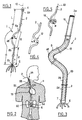
- la figure 1 est une vue en perspective du dispositif selon l'invention, pourvu d'une prothèse vasculaire et représenté dans un état de repos,
- la figure 2 est une vue en coupe schématique du corps d'un patient dans lequel est implanté le dispositif de la figure 1,
- la figure 3 montre en vue agrandie en perspective une partie du dispositif de la figure 1,
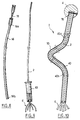
- les figures 4 et 5 sont des variantes de réalisation de la zone courbée de la tige de la figure 1,
- les figures 6 et 7 montrent en vue en coupe, partielle et agrandie, des variantes de réalisation du dispositif de la figure 1,
- les figures 8 et 9 montrent certains des principaux moyens utilisés pour la mise en place ou le retrait du dispostif de l'invention, et
- la figure 10 montre en coupe une autre variante du dispositif de la figure 1.
- FIG. 1 is a perspective view of the device according to the invention, provided with a vascular prosthesis and shown in a state of rest,
- FIG. 2 is a schematic sectional view of the body of a patient in which the device of FIG. 1 is implanted,
- Figure 3 shows in enlarged view in perspective part of the device of FIG. 1,
- FIGS. 4 and 5 are alternative embodiments of the curved zone of the rod of FIG. 1,
- FIGS. 6 and 7 show in sectional view, partial and enlarged, alternative embodiments of the device of FIG. 1,
- FIGS. 8 and 9 show some of the main means used for installing or removing the device of the invention, and
- FIG. 10 shows in section another variant of the device of FIG. 1.
L'un des intérêts de l'utilisation de ce dispositif étant de pouvoir améliorer les conditions d'implantation des filtres sanguins temporaires, on ne décrira ci-après l'invention que dans le cadre d'une telle application, même s'il doit être clair qu'elle peut s'appliquer à d'autres "prothèses médicales", même non vasculaires.One of the advantages of using this device being to be able to improve the conditions for implanting temporary blood filters, the invention will only be described below in the context of such an application, even if it must be clear that it can be applied to other "medical prostheses", even non-vascular.
Sur la figure 1, on voit donc illustrée dans son ensemble une unité temporaire de filtration sanguine 1, d'axe général sensiblement rectiligne 10, pouvant être mise en place par voie percutanée, ou par dénudation.In FIG. 1, there can therefore be seen illustrated as a whole a temporary
Le dispositif 1 comprend essentiellement une tige souple 2, d'axe 22 colinéaire avec celui du dispositif et de longueur L, avec une extrémité proximale 2a et une extrémité distale opposée 2b. Cette tige, avantageusement entourée d'une fine gaine 23 de protection, par exemple en silicone, pourra être pleine (figure 6, 10) ou présenter un passage intérieur 3 (figures 3, 7).The
La tige 2 pourra présenter une rigidité axiale sensiblement constante (figure 6) ou variable (figures 3, 7) sur sa longueur. Elle sera alors plus raide du côté de son extrémité distale, la rigidité allant en diminuant par tronçons, en direction de l'extrémité proximale où la tige est la plus souple. Pour faire varier cette rigidité, on pourra notamment utiliser des tubes coaxiaux 16, 18, de différentes longueurs, avec un ressort métallique hélicoïdal 24 noyé dans la paroi du tube 16, vers son extrémité distale (figure 3), ou encore un unique tube 30 d'épaisseur sensiblement constante dans la paroi duquel est noyé un ressort hélicoïdal 28 dont le "pas" entre spires va en décroissant progressivement (figure 7) depuis l'extrémité distale. Pour plus de détails, on se reportera à la demande française N° 92 13909 du 19/11/1992, correspondant à US-08/152361 du 16/11/1993.The
A son extrémité proximale, la tige ou cathéter est ici reliée à une "olive de repérage" 4 classique destinée à permettre de loger la tige entièrement en sous-cutané, cet embout 4 renflé en facilitant le repérage, par palpation à travers la peau (voir EP-A-0521222 ou US-07/731536 du 17/07/1991). Si la tige est creuse, on pourrait même prévoir d'utiliser, en alternative, une chambre implantable de distribution d'un produit traitant, telle que décrite dans la demande française précitée N° 92 13909.At its proximal end, the rod or catheter is here connected to a conventional "locating olive" 4 intended to allow the rod to be housed entirely subcutaneously, this
A son extrémité distale, la tige est reliée à un filtre sanguin 6 classique qui présente, en position déployée, une forme générale de corolle conique. Ce filtre comprend ici cinq pattes toutes issues d'une tête commune 7 et dépourvues de tout moyen d'ancrage au vaisseau.At its distal end, the rod is connected to a
Ces pattes pourront être auto-expansibles pour avoir naturellement tendance à se déployer radialement jusqu'à ce que leur extrémité libre vienne au contact du vaisseau, sans pour autant donc s'y accrocher.These legs may be self-expanding so as to have a natural tendency to deploy radially until their free end comes into contact with the vessel, without therefore clinging to it.
Le filtre, en général métallique, pourra être fixé à la tige par sertissage et/ou collage de sa tête 7.The filter, generally metallic, can be fixed to the rod by crimping and / or gluing its
Ce filtre 6 étant destiné à être implanté à l'intérieur d'un vaisseau sanguin, ici la veine cave inférieure 50, on a constaté qu'il était particulièrement soumis aux fluctuations du flux sanguin ainsi qu'à d'autres contraintes mécaniques telles que celles occasionnées par les mouvements du patient ou encore à la poussée que peut éventuellement exercer sur lui un caillot de sang. Or, de telles contraintes diverses tendent à se propager le long de la tige, celle-ci étant également dans le flux sanguin. L'organe de repérage 4 peut alors être soumis à déplacement, ce qui est peu confortable pour le patient et risque même d'entraîner des complications annexes.This
Pour assurer une bonne stabilité du dispositif dans son ensemble, celui-ci présente localement, conformément à l'invention, une zone infléchie ou courbée d'amortissement. Cette zone courbée, ici prévue pour être implantée dans l'oreillette droite du coeur, forme une sorte de "ressort" de maintien de l'unité 1, sensiblement dans la position voulue par le praticien au moment de l'implantation.To ensure good stability of the device as a whole, it has locally, in accordance with the invention, a bent or curved damping zone. This curved zone, here intended to be implanted in the right atrium of the heart, forms a sort of "spring" for holding the
Figures 1 et 3, la zone courbée repérée 8, consiste en une portion intermédiaire de la tige elle-même, ici sensiblement en arc plan, avec une extrémité proximale 8a et une extrémité distale 8b.Figures 1 and 3, the curved zone marked 8, consists of an intermediate portion of the rod itself, here substantially in planar arc, with a
Pour obtenir cette "préforme" courbe, la tige 2 pourra être constituée par exemple en une matière thermoplastique biocompatible, telle que du polyuréthane ou du polyamide, chauffée à l'endroit de sa portion 8, jusqu'à ramolissement de sa matière. A cette température (de l'ordre du point VICAT) inférieure à celle de fusion, la tige peut être courbée à volonté et conserve, après refroidissement, dans un état de repos non contraint, sensiblement la forme courbée imposée, tout en demeurant flexible sensiblement élastiquement. En alternative, on pourrait aussi réaliser la tige en silicone extrudé, par exemple dans un état semi-réticulé, puis mis dans sa forme courbe dans un moule où la réticulation se termine.To obtain this curved "preform", the
Quoi qu'il en soit, cette zone 8 pourra ensuite être aisément déformée pour s'étendre linéairement suivant l'axe 10 lors de la phase d'introduction de la tige dans l'organisme du patient, tout en formant, une fois la tige libérée, le "ressort" précité de stabilisation, en cas de poussée, voire de traction, exercée sur la tige en particulier par le filtre 6.Anyway, this
A noter que la zone courbée comprend un repère radio-opaque 48, tel une bague métallique, permettant au praticien de pouvoir la repérer dans l'organisme.Note that the curved area includes a
Les figures 4 et 5 montrent deux variantes de réalisation de cette zone qui, à la figure 4, se présente sous la forme générale d'un serpentin 12 sensiblement plan, tandis qu'à la figure 5, elle se développe en s'enroulant sensiblement suivant l'axe 22, telle une spirale ou hélice 14 à au moins une spire.Figures 4 and 5 show two alternative embodiments of this area which, in Figure 4, is in the general form of a substantially
Aux figures 6 et 7, la tige n'a pas été préformée courbée, mais on lui a adjoint une pièce de mise en forme 40, 42, d'axe 36, courbe dans un état de repos et montée glissante avec un faible jeu radial le long de la tige, pour un positionnement de la zone courbée adapté à chaque morphologie. Cette pièce, bien que souple, présente une rigidité supérieure ou égale à celle de la tige.In FIGS. 6 and 7, the rod has not been preformed curved, but there has been added to it a shaping
Sur la figure 6, la pièce en question est un tube flexible 40, tandis qu'à la figure 7, il s'agit d'un cylindre plastique 42, glissé dans le passage 3 de la tige qui est alors creuse.In FIG. 6, the part in question is a
Ces pièces 40 ou 42, seront de préférence pourvues d'un repère radio-opaque 48 et pourront être réalisées en plastique ou en élastomère avec préformage d'une portion au moins de leur longueur (Lp), comme précédemment décrit. Cette portion de maintien de la forme de la tige, avec une extrémité distale (40b, 42b) et une extrémité proximale (40a, 42a), peut être prolongée vers l'extrémité proximale de la tige par une partie 44, 46 non préformée (en pointillés sur les figures 6 et 7).These
En relation avec les figures 2, 8 et 9, nous allons à présent décrire une méthode possible d'implantation de l'unité de filtration, par voie percutanée, dans la veine cave inférieure 50 d'un patient H.In relation to FIGS. 2, 8 and 9, we will now describe a possible method of implantation of the filtration unit, by percutaneous route, in the
Comme décrit dans la demande française N° 92 13909, l'opérateur peut d'abord ménager dans le cou une voie d'accès percutanée VA de la veine jugulaire 58. Il insère ensuite, sur un guide-fil et un dilatateur (non représentés), une gaine introductrice 56 à travers la veine 58, la veine cave supérieure 52 et enfin la veine cave inférieure 50 jusqu'à la zone d'implantation 54 du filtre.As described in French application No. 92 13909, the operator can first provide a percutaneous access route VA of the
Une fois la gaine tubulaire 56 en position, elle sert de guide pour la mise en place du filtre, lequel est habituellement préconditionné à l'état radialement rapproché de ses pattes dans une sorte de seringue de conditionnement 60 vissée sur l'embout proximal 56a de la gaine qui débouche hors du corps du patient.Once the
L'opérateur fait alors descendre le filtre toujours replié (avec la tige éventuellement temporairement rigidifiée à sa suite) dans la gaine jusqu'à ce que le filtre parvienne à l'extrémité distale 56b de la gaine. Il tire alors vers lui la gaine pour que le filtre soit libéré et s'expanse naturellement.The operator then lowers the still folded filter (with the rod possibly temporarily stiffened after it) in the sheath until the filter reaches the
La gaine remontant, elle libère à son tour, dans l'oreillette droite 72, la zone 8 laquelle se déploie pour prendre sa courbure naturelle et vient en appui, au moins en partie, contre la paroi de l'oreillette. Cette zone déployée sera avantageusement écartée de l'axe 10, de telle sorte que son encombrement radial maximal e soit au moins égal au diamètre de la veine 50 ou 52, cette zone se trouvant alors bloquée dans l'oreillette jusqu'au moment du retrait éventuel du dispositif.The sheath rising, it in turn releases, in the
Dans le cas où le dispositif comporte une pièce annexe 40, 42, la gaine 56 est remontée, après la libération du filtre, jusque vers l'oreillette droite (légèrement en dessous). La pièce 40, 42 est alors introduite dans la gaine et est descendue jusqu'à son extrémité 56b éventuellement à l'aide d'un poussoir, tel que 78.In the case where the device comprises an
Une fois la pièce annexe arrivée à l'extrémité 56b de la gaine, elle est alors expulsée hors de celle-ci et adopte sa forme courbée à l'intérieur de l'oreillette. L'opérateur peut alors retirer totalement la gaine 56.Once the annex room has reached the
Il ne lui reste plus qu'à raccorder l'extrémité proximale de la tige à "l'olive" retenue, via par exemple le poinçon 76, après avoir sectionné à longueur convenable la tige. Il enfouit ensuite le tout dans les tissus et referme la voie d'accès. Lorsque le praticien désire retirer le dispositif, il peut par exemple, après avoir pratiqué une petite incision aux environs de l'élément 4, tirer sur la tige en forçant la zone courbée à s'extraire de l'oreillette 72 en se déformant.It only remains for him to connect the proximal end of the rod to the retained "olive", for example via the
A titre d'exemple, la tige pourra présenter une longueur L comprise entre environ 60 cm et 90 cm et un diamètre extérieur compris entre 2 mm et 5 mm environ. La zone courbée présentera une longueur (dans un état allongé) comprise entre environ 50 mm et 80 mm et de préférence d'environ 70 mm, la distance d séparant les extrémités distales de la zone courbée de celle de la tige pouvant varier de 60 mm à 100 mm environ et être par exemple égale à environ 80 mm.For example, the rod may have a length L of between approximately 60 cm and 90 cm and an outside diameter of between 2 mm and 5 mm approximately. The curved zone will have a length (in an elongated state) of between approximately 50 mm and 80 mm and preferably of approximately 70 mm, the distance d separating the distal ends of the curved zone from that of the rod may vary from 60 mm at approximately 100 mm and for example be equal to approximately 80 mm.
Bien entendu, l'invention n'est nullement limitée aux modes de réalisation ci-dessus ; ainsi, suivant une variante, on pourra prévoir que la zone courbée soit réalisée au moins en partie en un matériau a mémoire de forme thermique tel que du "NITINOL" (marque déposée, alliage à base de nickel et de titane), reprenant sa forme naturellement et localement, une fois chauffée par le flux sanguin.Of course, the invention is in no way limited to the above embodiments; thus, according to a variant, provision may be made for the curved zone to be produced at least in part from a memory material with thermal shape such as "NITINOL" (registered trademark, alloy based on nickel and titanium), resuming its shape naturally and locally, once heated by blood flow.
Suivant une autre variante illustrée figure 10, on pourrait prévoir une gaine souple 70 entourant la tige 2 (ici pleine) avec un certain jeu. Cette gaine, fixée au filtre à son extrémité distale 70b, aurait une longueur proche de celle de la tige. Elle permettrait le coulissement aisé de la pièce tubulaire 40 entre elle et la tige.According to another variant illustrated in FIG. 10, one could provide a
Dans d'autres cas d'implantation de la tige flexible, on pourrait également concevoir que la zone-ressort de la tige soit placée dans une cavité autre que l'oreillette 72 du coeur, voire à l'endroit d'un embranchement de vaisseaux.In other cases of implantation of the flexible rod, it could also be conceived that the spring zone of the rod is placed in a cavity other than the
Claims (13)
Applications Claiming Priority (2)
| Application Number | Priority Date | Filing Date | Title |
|---|---|---|---|
| FR9401344A FR2715827B1 (en) | 1994-02-07 | 1994-02-07 | Implantable medical device in the body of a patient, with axially stabilized rod, rod and curved part for this purpose and their production method. |
| FR9401344 | 1994-02-07 |
Publications (1)
| Publication Number | Publication Date |
|---|---|
| EP0670150A1 true EP0670150A1 (en) | 1995-09-06 |
Family
ID=9459843
Family Applications (1)
| Application Number | Title | Priority Date | Filing Date |
|---|---|---|---|
| EP95400209A Withdrawn EP0670150A1 (en) | 1994-02-07 | 1995-02-01 | Axially stabilized endovascular bloodfilter |
Country Status (2)
| Country | Link |
|---|---|
| EP (1) | EP0670150A1 (en) |
| FR (1) | FR2715827B1 (en) |
Families Citing this family (1)
| Publication number | Priority date | Publication date | Assignee | Title |
|---|---|---|---|---|
| FR2774895B1 (en) * | 1998-02-16 | 2000-06-30 | Braun Celsa Sa | MEDICAL DEVICE COMPRISING A ROD PROVIDED WITH A MEANS FOR ABSORBING AXIAL CONSTRAINTS |
Citations (5)
| Publication number | Priority date | Publication date | Assignee | Title |
|---|---|---|---|---|
| US4033331A (en) * | 1975-07-17 | 1977-07-05 | Guss Stephen B | Cardiac catheter and method of using same |
| US4454888A (en) * | 1981-10-07 | 1984-06-19 | Cordis Corporation | Cardiac pacing lead with curve retainer |
| EP0323738A2 (en) * | 1988-01-06 | 1989-07-12 | Namic U.S.A. Corporation | Catheters |
| US4882777A (en) * | 1987-04-17 | 1989-11-21 | Narula Onkar S | Catheter |
| US5152777A (en) * | 1989-01-25 | 1992-10-06 | Uresil Corporation | Device and method for providing protection from emboli and preventing occulsion of blood vessels |
-
1994
- 1994-02-07 FR FR9401344A patent/FR2715827B1/en not_active Expired - Fee Related
-
1995
- 1995-02-01 EP EP95400209A patent/EP0670150A1/en not_active Withdrawn
Patent Citations (5)
| Publication number | Priority date | Publication date | Assignee | Title |
|---|---|---|---|---|
| US4033331A (en) * | 1975-07-17 | 1977-07-05 | Guss Stephen B | Cardiac catheter and method of using same |
| US4454888A (en) * | 1981-10-07 | 1984-06-19 | Cordis Corporation | Cardiac pacing lead with curve retainer |
| US4882777A (en) * | 1987-04-17 | 1989-11-21 | Narula Onkar S | Catheter |
| EP0323738A2 (en) * | 1988-01-06 | 1989-07-12 | Namic U.S.A. Corporation | Catheters |
| US5152777A (en) * | 1989-01-25 | 1992-10-06 | Uresil Corporation | Device and method for providing protection from emboli and preventing occulsion of blood vessels |
Also Published As
| Publication number | Publication date |
|---|---|
| FR2715827B1 (en) | 1996-04-19 |
| FR2715827A1 (en) | 1995-08-11 |
Similar Documents
| Publication | Publication Date | Title |
|---|---|---|
| EP0521222B1 (en) | Device for temporary implanting a blood filter into a vein of the human body | |
| FR2710833A1 (en) | Device for implanting a medical prosthesis in a conduit of a human or animal body and method of centering such a device. | |
| EP1401359B1 (en) | Kit enabling a prosthetic valve to be placed in a body enabling a prosthetic valve to be put into place in a duct in the body | |
| CA2389713C (en) | Device for replacing a cardiac valve by percutaneous route | |
| EP0605276B1 (en) | Device for selective use as a temporary blood-filter | |
| EP0575478B1 (en) | Improved pulmonary embolism prevention filter and associated positioning and fitting kit | |
| EP1865886B1 (en) | Kit designed to be implanted in a bloodstream duct, and related tubular endoprosthesis | |
| CA2263112C (en) | Stent delivery system with storage sleeve | |
| FR2694687A1 (en) | Intra-vascular prosthesis for blood filtration and clot prevention - comprises series of flexible threads formed into arrangement of shaped loops, secured to distal end of tubular support portion | |
| EP0935975A1 (en) | Medical device having a shaft provided with absorbtion means for axial stress | |
| FR2714815A1 (en) | Elastic prosthesis to widen a conduit, especially a blood vessel. | |
| FR2822370A1 (en) | TUBULAR ENDOPROSTHESIS COMPRISING A DEFORMABLE RING AND NECESSARY INTERVENTION FOR ITS IMPLANTATION | |
| FR3006884A1 (en) | ATRAUMATIC DEVICE FOR INTRODUCING A HOLLOW TUBULAR ELEMENT IN A BIOLOGICAL ORGAN | |
| FR2697995A1 (en) | Removable blood filtration device, with variable rigidity, implantable in the body of a patient and allowing the injection of a treatment product. | |
| FR2701648A1 (en) | Prosthesis intended for the treatment of a light or natural way, in particular endo-urethral prosthesis. | |
| WO1994004096A1 (en) | Expansible tubular prosthesis | |
| EP2427139A1 (en) | Extraction kit for a filter for the vena cava | |
| EP0670150A1 (en) | Axially stabilized endovascular bloodfilter | |
| EP0935976B1 (en) | Flexible biocompatible shaft to be implanted into a body duct and device fitted with such a shaft | |
| EP1153580A1 (en) | Manufacturing method for an intravascular deflector and resulting implant | |
| FR2843297A1 (en) | Medical set for treatment of body conduit affection comprises intraluminal prosthesis and introducer comprising tubular sheath and long interior element | |
| EP0941038B1 (en) | MEDICAL SET FOR INTERVENTION ON AN ANATOMICAL DUCT and appertaining SEALING RING | |
| FR2774893A1 (en) | Medical implant with biocompatible flexible tube | |
| WO2021064303A1 (en) | Device for placing and fastening a reinforcement implant on a mitral valve of a heart with shape-memory sutures using a transfemoral approach | |
| WO2001097716A1 (en) | Metal sheet sealing system for an internal vascular prosthesis |
Legal Events
| Date | Code | Title | Description |
|---|---|---|---|
| PUAI | Public reference made under article 153(3) epc to a published international application that has entered the european phase |
Free format text: ORIGINAL CODE: 0009012 |
|
| AK | Designated contracting states |
Kind code of ref document: A1 Designated state(s): BE DE ES GB IT |
|
| 17P | Request for examination filed |
Effective date: 19960209 |
|
| 17Q | First examination report despatched |
Effective date: 19980122 |
|
| STAA | Information on the status of an ep patent application or granted ep patent |
Free format text: STATUS: THE APPLICATION IS DEEMED TO BE WITHDRAWN |
|
| 18D | Application deemed to be withdrawn |
Effective date: 19990126 |