EP0672831A2 - Apparatus and method for supercritical fluid extraction - Google Patents
Apparatus and method for supercritical fluid extraction Download PDFInfo
- Publication number
- EP0672831A2 EP0672831A2 EP95102984A EP95102984A EP0672831A2 EP 0672831 A2 EP0672831 A2 EP 0672831A2 EP 95102984 A EP95102984 A EP 95102984A EP 95102984 A EP95102984 A EP 95102984A EP 0672831 A2 EP0672831 A2 EP 0672831A2
- Authority
- EP
- European Patent Office
- Prior art keywords
- fluid
- pressure
- piston
- pump
- flow
- Prior art date
- Legal status (The legal status is an assumption and is not a legal conclusion. Google has not performed a legal analysis and makes no representation as to the accuracy of the status listed.)
- Granted
Links
Images


Classifications
-
- G—PHYSICS
- G01—MEASURING; TESTING
- G01N—INVESTIGATING OR ANALYSING MATERIALS BY DETERMINING THEIR CHEMICAL OR PHYSICAL PROPERTIES
- G01N1/00—Sampling; Preparing specimens for investigation
- G01N1/28—Preparing specimens for investigation including physical details of (bio-)chemical methods covered elsewhere, e.g. G01N33/50, C12Q
- G01N1/34—Purifying; Cleaning
-
- B—PERFORMING OPERATIONS; TRANSPORTING
- B01—PHYSICAL OR CHEMICAL PROCESSES OR APPARATUS IN GENERAL
- B01D—SEPARATION
- B01D11/00—Solvent extraction
- B01D11/02—Solvent extraction of solids
- B01D11/0203—Solvent extraction of solids with a supercritical fluid
-
- B—PERFORMING OPERATIONS; TRANSPORTING
- B01—PHYSICAL OR CHEMICAL PROCESSES OR APPARATUS IN GENERAL
- B01D—SEPARATION
- B01D11/00—Solvent extraction
- B01D11/04—Solvent extraction of solutions which are liquid
- B01D11/0403—Solvent extraction of solutions which are liquid with a supercritical fluid
- B01D11/0407—Solvent extraction of solutions which are liquid with a supercritical fluid the supercritical fluid acting as solvent for the solute
-
- F—MECHANICAL ENGINEERING; LIGHTING; HEATING; WEAPONS; BLASTING
- F04—POSITIVE - DISPLACEMENT MACHINES FOR LIQUIDS; PUMPS FOR LIQUIDS OR ELASTIC FLUIDS
- F04B—POSITIVE-DISPLACEMENT MACHINES FOR LIQUIDS; PUMPS
- F04B15/00—Pumps adapted to handle specific fluids, e.g. by selection of specific materials for pumps or pump parts
- F04B15/06—Pumps adapted to handle specific fluids, e.g. by selection of specific materials for pumps or pump parts for liquids near their boiling point, e.g. under subnormal pressure
- F04B15/08—Pumps adapted to handle specific fluids, e.g. by selection of specific materials for pumps or pump parts for liquids near their boiling point, e.g. under subnormal pressure the liquids having low boiling points
-
- F—MECHANICAL ENGINEERING; LIGHTING; HEATING; WEAPONS; BLASTING
- F04—POSITIVE - DISPLACEMENT MACHINES FOR LIQUIDS; PUMPS FOR LIQUIDS OR ELASTIC FLUIDS
- F04B—POSITIVE-DISPLACEMENT MACHINES FOR LIQUIDS; PUMPS
- F04B49/00—Control, e.g. of pump delivery, or pump pressure of, or safety measures for, machines, pumps, or pumping installations, not otherwise provided for, or of interest apart from, groups F04B1/00 - F04B47/00
- F04B49/06—Control using electricity
- F04B49/065—Control using electricity and making use of computers
-
- F—MECHANICAL ENGINEERING; LIGHTING; HEATING; WEAPONS; BLASTING
- F04—POSITIVE - DISPLACEMENT MACHINES FOR LIQUIDS; PUMPS FOR LIQUIDS OR ELASTIC FLUIDS
- F04B—POSITIVE-DISPLACEMENT MACHINES FOR LIQUIDS; PUMPS
- F04B53/00—Component parts, details or accessories not provided for in, or of interest apart from, groups F04B1/00 - F04B23/00 or F04B39/00 - F04B47/00
- F04B53/08—Cooling; Heating; Preventing freezing
-
- F—MECHANICAL ENGINEERING; LIGHTING; HEATING; WEAPONS; BLASTING
- F04—POSITIVE - DISPLACEMENT MACHINES FOR LIQUIDS; PUMPS FOR LIQUIDS OR ELASTIC FLUIDS
- F04B—POSITIVE-DISPLACEMENT MACHINES FOR LIQUIDS; PUMPS
- F04B53/00—Component parts, details or accessories not provided for in, or of interest apart from, groups F04B1/00 - F04B23/00 or F04B39/00 - F04B47/00
- F04B53/14—Pistons, piston-rods or piston-rod connections
- F04B53/143—Sealing provided on the piston
-
- F—MECHANICAL ENGINEERING; LIGHTING; HEATING; WEAPONS; BLASTING
- F04—POSITIVE - DISPLACEMENT MACHINES FOR LIQUIDS; PUMPS FOR LIQUIDS OR ELASTIC FLUIDS
- F04B—POSITIVE-DISPLACEMENT MACHINES FOR LIQUIDS; PUMPS
- F04B9/00—Piston machines or pumps characterised by the driving or driven means to or from their working members
- F04B9/02—Piston machines or pumps characterised by the driving or driven means to or from their working members the means being mechanical
- F04B9/04—Piston machines or pumps characterised by the driving or driven means to or from their working members the means being mechanical the means being cams, eccentrics or pin-and-slot mechanisms
- F04B9/042—Piston machines or pumps characterised by the driving or driven means to or from their working members the means being mechanical the means being cams, eccentrics or pin-and-slot mechanisms the means being cams
-
- F—MECHANICAL ENGINEERING; LIGHTING; HEATING; WEAPONS; BLASTING
- F16—ENGINEERING ELEMENTS AND UNITS; GENERAL MEASURES FOR PRODUCING AND MAINTAINING EFFECTIVE FUNCTIONING OF MACHINES OR INSTALLATIONS; THERMAL INSULATION IN GENERAL
- F16K—VALVES; TAPS; COCKS; ACTUATING-FLOATS; DEVICES FOR VENTING OR AERATING
- F16K15/00—Check valves
- F16K15/18—Check valves with actuating mechanism; Combined check valves and actuated valves
- F16K15/182—Check valves with actuating mechanism; Combined check valves and actuated valves with actuating mechanism
- F16K15/1823—Check valves with actuating mechanism; Combined check valves and actuated valves with actuating mechanism for ball check valves
-
- G—PHYSICS
- G01—MEASURING; TESTING
- G01F—MEASURING VOLUME, VOLUME FLOW, MASS FLOW OR LIQUID LEVEL; METERING BY VOLUME
- G01F1/00—Measuring the volume flow or mass flow of fluid or fluent solid material wherein the fluid passes through a meter in a continuous flow
- G01F1/05—Measuring the volume flow or mass flow of fluid or fluent solid material wherein the fluid passes through a meter in a continuous flow by using mechanical effects
- G01F1/34—Measuring the volume flow or mass flow of fluid or fluent solid material wherein the fluid passes through a meter in a continuous flow by using mechanical effects by measuring pressure or differential pressure
-
- G—PHYSICS
- G01—MEASURING; TESTING
- G01N—INVESTIGATING OR ANALYSING MATERIALS BY DETERMINING THEIR CHEMICAL OR PHYSICAL PROPERTIES
- G01N1/00—Sampling; Preparing specimens for investigation
- G01N1/28—Preparing specimens for investigation including physical details of (bio-)chemical methods covered elsewhere, e.g. G01N33/50, C12Q
- G01N1/40—Concentrating samples
-
- G—PHYSICS
- G01—MEASURING; TESTING
- G01N—INVESTIGATING OR ANALYSING MATERIALS BY DETERMINING THEIR CHEMICAL OR PHYSICAL PROPERTIES
- G01N30/00—Investigating or analysing materials by separation into components using adsorption, absorption or similar phenomena or using ion-exchange, e.g. chromatography or field flow fractionation
- G01N30/02—Column chromatography
- G01N30/26—Conditioning of the fluid carrier; Flow patterns
- G01N30/28—Control of physical parameters of the fluid carrier
-
- G—PHYSICS
- G21—NUCLEAR PHYSICS; NUCLEAR ENGINEERING
- G21F—PROTECTION AGAINST X-RADIATION, GAMMA RADIATION, CORPUSCULAR RADIATION OR PARTICLE BOMBARDMENT; TREATING RADIOACTIVELY CONTAMINATED MATERIAL; DECONTAMINATION ARRANGEMENTS THEREFOR
- G21F5/00—Transportable or portable shielded containers
- G21F5/015—Transportable or portable shielded containers for storing radioactive sources, e.g. source carriers for irradiation units; Radioisotope containers
-
- F—MECHANICAL ENGINEERING; LIGHTING; HEATING; WEAPONS; BLASTING
- F04—POSITIVE - DISPLACEMENT MACHINES FOR LIQUIDS; PUMPS FOR LIQUIDS OR ELASTIC FLUIDS
- F04B—POSITIVE-DISPLACEMENT MACHINES FOR LIQUIDS; PUMPS
- F04B2201/00—Pump parameters
- F04B2201/02—Piston parameters
- F04B2201/0209—Duration of piston stroke
-
- F—MECHANICAL ENGINEERING; LIGHTING; HEATING; WEAPONS; BLASTING
- F04—POSITIVE - DISPLACEMENT MACHINES FOR LIQUIDS; PUMPS FOR LIQUIDS OR ELASTIC FLUIDS
- F04B—POSITIVE-DISPLACEMENT MACHINES FOR LIQUIDS; PUMPS
- F04B2205/00—Fluid parameters
- F04B2205/03—Pressure in the compression chamber
-
- F—MECHANICAL ENGINEERING; LIGHTING; HEATING; WEAPONS; BLASTING
- F04—POSITIVE - DISPLACEMENT MACHINES FOR LIQUIDS; PUMPS FOR LIQUIDS OR ELASTIC FLUIDS
- F04B—POSITIVE-DISPLACEMENT MACHINES FOR LIQUIDS; PUMPS
- F04B2205/00—Fluid parameters
- F04B2205/05—Pressure after the pump outlet
-
- F—MECHANICAL ENGINEERING; LIGHTING; HEATING; WEAPONS; BLASTING
- F04—POSITIVE - DISPLACEMENT MACHINES FOR LIQUIDS; PUMPS FOR LIQUIDS OR ELASTIC FLUIDS
- F04B—POSITIVE-DISPLACEMENT MACHINES FOR LIQUIDS; PUMPS
- F04B2205/00—Fluid parameters
- F04B2205/09—Flow through the pump
-
- F—MECHANICAL ENGINEERING; LIGHTING; HEATING; WEAPONS; BLASTING
- F05—INDEXING SCHEMES RELATING TO ENGINES OR PUMPS IN VARIOUS SUBCLASSES OF CLASSES F01-F04
- F05B—INDEXING SCHEME RELATING TO WIND, SPRING, WEIGHT, INERTIA OR LIKE MOTORS, TO MACHINES OR ENGINES FOR LIQUIDS COVERED BY SUBCLASSES F03B, F03D AND F03G
- F05B2230/00—Manufacture
- F05B2230/40—Heat treatment
- F05B2230/41—Hardening; Annealing
-
- F—MECHANICAL ENGINEERING; LIGHTING; HEATING; WEAPONS; BLASTING
- F05—INDEXING SCHEMES RELATING TO ENGINES OR PUMPS IN VARIOUS SUBCLASSES OF CLASSES F01-F04
- F05C—INDEXING SCHEME RELATING TO MATERIALS, MATERIAL PROPERTIES OR MATERIAL CHARACTERISTICS FOR MACHINES, ENGINES OR PUMPS OTHER THAN NON-POSITIVE-DISPLACEMENT MACHINES OR ENGINES
- F05C2201/00—Metals
- F05C2201/04—Heavy metals
- F05C2201/0469—Other heavy metals
- F05C2201/0493—Tin
-
- F—MECHANICAL ENGINEERING; LIGHTING; HEATING; WEAPONS; BLASTING
- F05—INDEXING SCHEMES RELATING TO ENGINES OR PUMPS IN VARIOUS SUBCLASSES OF CLASSES F01-F04
- F05C—INDEXING SCHEME RELATING TO MATERIALS, MATERIAL PROPERTIES OR MATERIAL CHARACTERISTICS FOR MACHINES, ENGINES OR PUMPS OTHER THAN NON-POSITIVE-DISPLACEMENT MACHINES OR ENGINES
- F05C2253/00—Other material characteristics; Treatment of material
- F05C2253/12—Coating
-
- G—PHYSICS
- G01—MEASURING; TESTING
- G01N—INVESTIGATING OR ANALYSING MATERIALS BY DETERMINING THEIR CHEMICAL OR PHYSICAL PROPERTIES
- G01N1/00—Sampling; Preparing specimens for investigation
- G01N1/28—Preparing specimens for investigation including physical details of (bio-)chemical methods covered elsewhere, e.g. G01N33/50, C12Q
- G01N1/40—Concentrating samples
- G01N1/4022—Concentrating samples by thermal techniques; Phase changes
- G01N2001/4033—Concentrating samples by thermal techniques; Phase changes sample concentrated on a cold spot, e.g. condensation or distillation
-
- G—PHYSICS
- G01—MEASURING; TESTING
- G01N—INVESTIGATING OR ANALYSING MATERIALS BY DETERMINING THEIR CHEMICAL OR PHYSICAL PROPERTIES
- G01N1/00—Sampling; Preparing specimens for investigation
- G01N1/28—Preparing specimens for investigation including physical details of (bio-)chemical methods covered elsewhere, e.g. G01N33/50, C12Q
- G01N1/40—Concentrating samples
- G01N1/4055—Concentrating samples by solubility techniques
- G01N2001/4061—Solvent extraction
-
- G—PHYSICS
- G01—MEASURING; TESTING
- G01N—INVESTIGATING OR ANALYSING MATERIALS BY DETERMINING THEIR CHEMICAL OR PHYSICAL PROPERTIES
- G01N30/00—Investigating or analysing materials by separation into components using adsorption, absorption or similar phenomena or using ion-exchange, e.g. chromatography or field flow fractionation
- G01N30/02—Column chromatography
- G01N30/60—Construction of the column
- G01N30/6004—Construction of the column end pieces
- G01N2030/6013—Construction of the column end pieces interfaces to detectors
-
- G—PHYSICS
- G01—MEASURING; TESTING
- G01N—INVESTIGATING OR ANALYSING MATERIALS BY DETERMINING THEIR CHEMICAL OR PHYSICAL PROPERTIES
- G01N35/00—Automatic analysis not limited to methods or materials provided for in any single one of groups G01N1/00 - G01N33/00; Handling materials therefor
- G01N35/02—Automatic analysis not limited to methods or materials provided for in any single one of groups G01N1/00 - G01N33/00; Handling materials therefor using a plurality of sample containers moved by a conveyor system past one or more treatment or analysis stations
- G01N35/04—Details of the conveyor system
- G01N2035/0439—Rotary sample carriers, i.e. carousels
- G01N2035/0441—Rotary sample carriers, i.e. carousels for samples
-
- G—PHYSICS
- G01—MEASURING; TESTING
- G01N—INVESTIGATING OR ANALYSING MATERIALS BY DETERMINING THEIR CHEMICAL OR PHYSICAL PROPERTIES
- G01N30/00—Investigating or analysing materials by separation into components using adsorption, absorption or similar phenomena or using ion-exchange, e.g. chromatography or field flow fractionation
- G01N30/02—Column chromatography
Definitions
- This invention relates to supercritical fluid extraction and more particularly relates to a reciprocating pump for pumping liquid near its supercritical temperature in such systems.
- an extraction vessel In supercritical fluid extraction, an extraction vessel is held at a temperature above the critical point and is supplied with fluid at a pressure above the critical pressure. Under these conditions, the fluid within the extraction vessel is a supercritical fluid.
- One prior art type of pump used for supercritical extraction is the same as a single piston pump used for HPLC.
- This type of pump has several disadvantages when used for supercritical fluid extraction, which are: (1) a regenerative effect may, under some circumstances, be created in which the heat of compression increases the temperature of the fluid which in turn increases its compressibility resulting in the regenerative effect that prevents the accurate prediction of flow rate for purposes of control; (2) the prior art pump cams of the pump create destructive reverse torques on the pump cams, gear trains and drive motors after the cams pass top dead center because the high compressibility of the liquid in the pump chambers cause storage of a relatively high amount of energy at high pressures.
- Another prior art pump used for supercritical fluid extraction is a multiple cylinder pump of the type now used in HPLC to reduce pulsation.
- This type of pump besides being sometimes under some circumstances subject to the problems of single cylinder pumps, is also more expensive and complicated.
- a cam for driving the piston that is to pump a supercritical fluid has a slow return stroke intended to reduce destructive forces.
- This type of pump has a disadvantage insofar as it causes pulsations and delays on time during which fluid is not delivered.
- a pumping system for supercritical extraction includes an inlet means, adapted to be connected to a source of supercritical fluid; outlet means, adapted to provide the pumped fluid to a pressure vessel; and pumphead means having a pumping chamber communicating with said inlet means and outlet means; a piston; an inlet valve means controlling the flow of fluid into said pumping chamber means through said inlet means; an outlet valve means controlling the flow of fluid from said pumping chamber means through said outlet means; an inlet conduit means defining a flow path between said inlet valve and said pump chamber; and an outlet conduit means defining a flow path between said pump chamber and said outlet valve means.
- the pumping system is characterized by an air-cooled thermoelectric-cooled heat exchanger means for cooling both an inlet means and the pumphead means.
- the inlet conduit means and outlet conduit means have a sufficiently small deadspace so that the compressibility ratio is greater than 2.1 to 1.
- the pump chamber has conductive metal walls, a piston and a piston sleeve of low heat conductivity and are substantially non-metallic at locations in contact with the fluid and the walls.
- the pump chamber is configured so that approximately half the volume of the fluid in the pump chamber is in contact with the pump chamber walls, whereby sufficient heat of compression is removed from the walls to avoid substantial temperature buildup.
- the heat exchange means is a metal with a thermal conductivity equal to or greater than aluminum.
- the heat exchange means is in contact with a pumphead block and a thermoelectric cooler is in contact with the heat exchanger.
- the heat exchanger has a volume at least twice the displacement of said pump.
- the flow rate of the liquid is greater than two milliliters per minute, and the heat exchange volume is greater than ten times the displacement of the pump.
- the length to diameter ratio of the wetted surface of the heat exchange means is more than 1,800 to one.
- the length of the heat exchanger flow path and the diameter of the flow path are in a ratio of at least 50 to one through at least 50 percent of the flow path.
- a rotating cam means has a cam with displacement slopes and a cooperating cam follower which varies the volume within a pumping chamber whereby said pumping chamber has within it liquid under pressure.
- the rotating cam has a repressurization surface, a delivery surface, a transition surface, a depressurization surface and a refill surface positioned to be traversed by the cam follower in that order and the depressurization surface has an initial displacement slope substantially equal to, but of the opposite sign of, the displacement slope of the final part of the delivery surface.
- the transition surface is rounded sufficiently to allow closing of the said outlet valve without damage and to keep Hertzian contact forces between the cam and cam follower low enough to prevent deformation.
- the depressurization surface is shaped to produce a continuously increasing linear velocity of the cam follower with respect to the cam rotation speed until the cam follower reaches the refill surface, at which time the velocity the cam follower moves with a more constant linear velocity with respect to the cam rotation speed as it runs along the refill surface, whereby the fluid is pressurized by a maximum pressure by the pumping system and transferred to a heating means that converts said pressurized fluid to supercritical fluid.
- the continuously increasing linear cam follower velocity of the depressurization surface corresponds to an acceleration of the linear velocity of the cam follower.
- the displacement slope is inversely proportional to the pressure within the pumping chamber when operating at the highest intended delivery pressure.
- the refill surface joins the depressurization surface without a discontinuity of slope and the refill surface has a comparatively constant displacement slope.
- the pumping system includes an instrument for measuring the outlet flow of fluid from the pump.
- This instrument is characterized by a flow onset sensing means for transducing a signal related to flow onset of high pressure fluid flow to a first electric signal; a sensing means for detecting the times at which the displacement means is substantially located at one of its said extreme positions during each of the said cycles of movement; a differentiating means for operating upon the first electric signal to produce a second electric signal dependent on rates of change in the first electric signal; a detection means for sensing the second electric signal and for detecting a change in the rate of change of the said high pressure during each of said cyclic motions of the said displacement means; and a switching means turned on for a time duration by the said detection means by the detecting means after the said start of the period of fluid delivery and turned off, terminating the said time duration, at the times detected by the sensing means.
- the displacement means has a position transducer whose output is a third electric signal proportional to displacement within the said pump chamber; a time integral means which cyclicly integrates the said third electric signal between time limits set by the said time duration during which the said switching means is on, and an amount proportional to the outlet flow of the pump.
- the instrument includes a utilization means that controls the flow rate.
- the flow onset sensing means includes a pressure transducer means for sensing the said liquid pressure within the pumping chamber.
- the differentiating means is a single differentiator, producing a first derivative signal.
- the detection means includes means for detecting a change in the first derivative signal from a high positive level to a lower positive level, and the sensing means includes means for detecting the time at which the displacement means displaces substantially the said maximum volume from the pumping chamber, wherein the flow and sensing means is a pressure sensor and the signal is a pressure signal or the flow and sensing means is a flow meter.
- the pressure transducer senses the liquid pressure within the pumping chamber, the differentiating means is a double differentiator, the detection means detects a change in the said second derivative from a zero level to a negative level or from a negative level to a positive level, and the sensing means detects the time at which the displacement means displaces substantially the said maximum volume from the pumping chamber.
- the pressure transducer senses the liquid pressure within the outlet line; the differentiating means is a single differentiator that produces a second electric signal proportional to the first derivative of the said pressure within the outlet line, and the sensing means includes means for detecting the time at which the displacement means displaces substantially at the said maximum volume from the pumping chamber.
- a seal has one side in contact with the supercritical fluid for blocking the flow of fluid past said piston and a support means for supporting said piston within said pump.
- the support means is located on the supercritical fluid side of the said seal.
- the piston means is supported on each of both sides of said seal, whereby said piston means is maintained in alignment as it reciprocates.
- a drive means applies force to said piston to push it forward in a direction that expels supercritical fluid from said chamber.
- the drive means includes means in contact with said piston means having a spherical surface with a radius large enough so as to have components perpendicular to the direction of motion less than 10 percent of the components of force in the direction of motion of the piston means.
- the contact with said spherical surface is a hertzian contact.
- a sleeve is attached to said piston for movement therewith; said sleeve having a cylindrical surface substantially in contact with cylindrical walls aligned with the direction of said piston, whereby said piston is maintained in alignment as it is moved.
- Measuring means for measuring the pumped supercritical fluid by determining pressure and movement of the piston and calculating fluid rate flow from piston movement and fluid pressure.
- the means for measuring pressure includes a strain gauge means adapted to be positioned in contact with said supercritical fluid and measuring piston movement includes an optical means mounted for movement in relation to the movement to said piston means; said pressure sensing means and means for measuring movement each including different means for generating electrical signals connected to a calculating means for determining the rate of flow of supercritical fluid.
- a drive means for driving said piston and feedback control means electrically connecting said drive means to said means for determining volumetric flow rate are provided wherein said volumetric flow rate of said supercritical fluid is controlled by said feedback means.
- a first and second sources of supercritical fluid are provided; first and second pumps; each of said first and second pumps having means for controlling the rate of pumping of said first and second pumps.
- the feedback means is connected to the first and second means for controlling said first and second pumps.
- the feedback means includes a controller wherein the rate of pumping of said first and second pumps is changed with respect to each other as said rate of flow of fluid changes to maintain a constant flow rate as the composition of said first and second fluid varies, said first and second valve means having an outlet means communicating with a mixer means.
- the mixer means communicate with the inlet to said pump means, wherein said feedback controls gradients supplied to said inlet means.
- a method of pumping comprising the steps of: pumping a fluid through an inlet means of a pumphead adapted to be connected to source of said fluid and from an outlet means of the pumphead, wherein the outlet means is adapted to provide the pumped fluid to a pressure vessel; characterized by cooling and inlet means and pumphead means using an air-cooled thermoelectric-cooled heat exchanger and by pumping at a flow rate of the liquid greater than two millileters per minute wherein the heat exchange volume volume is greater than ten times the displacement of the pump.
- volume is varied within a pumping chamber with a rotating cam having displacement slopes and a cooperating cam follower wherein the chamber has within it liquid under pressure.
- the cam is rotated so that a repressurization surface, a delivery surface, a transition surface, a depressurisation surface and a refill surface are traversed by the said cam follower in that order wherein said depressurization surface has an initial displacement slope substantially equal to, but of the opposite sign of, the displacement slope of the final part of the delivery surface; the transition surface being rounded sufficiently to allow closing of the said outlet valve without damage and keep Hertzian contact forces between the cam and cam follower low enough to prevent deformation; and said depressurization surface produces a continuously increasing linear velocity of the cam follower with respect to cam rotation speed until the cam follower reaches the said refill surface, at which time the velocity the cam follower moves with a more constant linear velocity with respect to cam rotation speed as it runs along refill surface.
- the said displacement slope is inversely proportional to said pressure within the said pumping chamber when operating at the highest intended delivery pressure.
- a signal is generated with a pressure transducer means which transduces the pressure of high pressure fluid flow to a first electric signal.
- the times at which the said displacement means is substantially located at one its said extreme positions during each of the said cycles of movement are detected and said first electric signal is differentiated to produce a second electric signal dependent on rates of change in the said first electric signal.
- the second electric signal is sensed and a change in the rate of change of the high pressure during each of said cyclic motions of the said displacement means is detected.
- a switching means is turned on for a time duration upon the detection the second electric signal after the start of the period of fluid delivery and is turned off at the end of the time duration.
- a third electric signal is generated with a position transducer, the output of which is proportional to displacement within the pump chamber.
- the third electric signal is cyclically integrated between time limits set by the time duration during which the switching means is on, and the integral is utilized as an amount proportional to the outlet flow of the pump.
- the switch means is turned on in response to detection means at the start of the period of fluid delivery and turned off at the finish of the period of fluid delivery and a second electric signal is generated on said displacement means with a position transduceer proportional to displacement within the said pump chamber.
- the second electric signal is cyclically integrated between time limits set by the time period during which the said switching means is on, and the integral is utilized as an amount proportional to the outlet flow of the pump.
- a change from the first derivative from a small positive to a large negative value to determine the finish of fluid delivery and a change in the said first derivative from a large positive value to a smaller positive value to determine the finish of fluid delivery are detected.
- a change in the said first derivative from a negative value to a positive value for determining a start of fluid delivery and a change in the said first derivative from a postive value to a negative value for determining a finish of fluid delivery are detected.
- the flow of fluid past a piston means is blocked by a seal wherein said piston is supported on each of both sides of said seal.
- the piston means is maintained in alignment as it reciprocates, its supercritical fluid is expelled from said chamber by pushing drive means forward to said piston.
- the drive means includes means in contact with said piston means having a spherical surface with a radius large enough to have components perpendicular to the direction of motion of less than 10 percent of the components of force in the direction of motion of the piston means.
- a sleeve is kept in contact with cylindrical walls aligned with the direction of said piston and said sleeve supporting said piston in alignment as it is moved.
- the pumped supercritical fluid is measured by determining pressure and movement of the piston and calculating fluid rate flow from piston movement and fluid pressure.
- the pressure is measured with a strain gauge means wherein the strain gauge means is positioned in contact with said supercritical fluid.
- the piston movement is measured by moving optical means mounted in relation to the movement to said piston means or by said means for movement in relation to the movement of said piston and the rate of flow of supercritical fluid is determined by generating electrical signals connected to a calculating means.
- the rate of pumping of said first and second pumps is controlled by controlling said first and second pumps by connecting feedback means to said first and second means and changing the rate of pumping of said first and second pumps with respect to each other as said rate of flow of fluid changes to maintain a constant flow rate as the composition of said first and second fluid varies.
- the first valve means and said second valve means are controlled by said feedback means which includes program means allowing said first valve means to communicate with a first source of supercritical fluid; allowing said second valve means to communicate with a second source of supercritical fluid; allowing said first and second valve means having outlet means to communicate with a mixer means; and allowing said mixer means to communicate with the inlet to said pump means.
- the feedback controls gradients supplied to said inlet means.
- the supercritical extraction technique has several advantages, such as for example: (1) it is more convenient than prior art extractors; (2) it automates the sample injection and fraction collection part of the extraction process as well as automating the extraction itself; (3) it is smaller and more compact becuase of the air-thermoelectric cooling the pumphead and the inlet fluid separately and simultaneously; (4) it may have a reasonably high flow rate; (5) seal life is lengthened by improving the alignment of the plunger within the seal; (6) fluid volume leaving the pump is precisely measured; and (7) no water cooling is required.
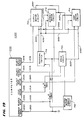
- FIG. 1 there is shown a schematic fluidic diagram of one channel of a dual-channel supercritical fluid extraction system 10 having a pumping system 12, a valve system 14, a collector system 16 and a pressure vessel and fluid-extraction assembly 18.
- the pumping system 12 communicates with two extraction cartridges within the pressure vessel and fluid-extraction assembly 18 and for this purpose is connected through a tee joint 20 to two identical valve systems, one of which is shown at 14.
- Each valve system communicates with a different one of two inlets for the corresponding one of two extraction cartridges.
- a specially designed pump (not shown in FIG. 1) for the supercritical extraction system is a cam-driven single-plunger pump having a cam profile that enables the pumping system to avoid destructive reverse torque on the cam, gear train and drive motor after the cam passes top dead center.
- the fluid volume leaving the pump is determined by measuring only pressure or other parameter related to flow and movement of the plunger. Measurement of the fluid volume leaving the pump is useful for recording or indicating the flow rate while the pump is operating as follows: (a) recording or indicating the flow volume or flow rate of the pump when the pump is operating at constant pressure; and (b) useful as feedback means for controlling the pump to provide constant flow.
- the fluid delivery volume or actual flow rate provides signals used for accurate formation of either high pressure (outlet side) or low pressure (inlet side) composition gradients.
- the pumphead and the inlet fluid are air-thermo-electrically cooled separately and simultaneously. It is surprising that air heat rejection is satisfactory as previous designs are water cooled or have very low flow rates. Also, there are surprising advantages over cooling just one but not the other as described in prior literature.
- the plunger or piston of the pump is supported on both sides of the seal to lengthen the seal life by improving the alignment of the plunger within the seal.
- the plunger support within the pumphead is the controlling locator of the seal and is machined concentric and collinear to the seal gland. This construction which increases seal life is particularly useful because pump head cooling makes seal replacement more difficult.
- valve system 14 and a second valve system which is connected to the other branch of the tee joint 20 are each connected to two different collector systems 16, one of which is shown in FIG. 1, and to different ones of the two extraction cartridges in the pressure-vessel and fluid-extraction assembly 18 so that, two extraction operations can be performed at the same time using the same pumping system 12.
- the valve system 14 causes: (1) supercritical fluid to flow from the pumping system 12 into a space between a cartridge and the interior of the pressure vessel of the pressure-vessel and fluid-extraction assembly 18 for purging the outside of the cartridge and the inside of the pressure vessel; and (2) applies supercritical fluid through the cartridge for extraction of a sample 134 therein. Because the fluid is applied both to the interior of the cartridge and the exterior, the cartridge does not have to withstand a high pressure difference between its interior and exterior and can be made economically.
- valve system 14 controls the flow of: (1) purging supercritical fluid from the space between the cartridge and interior of the vessel to the collector system 16 or to a vent; and (2) the extractant from the interior of the cartridge to the collector system 16 for separate collection.
- the pressure-vessel and fluid-extraction assembly 18 includes a heating block 22, a pressure vessel 24 and a cartridge and plug assembly 26 with the cartridge and plug assembly 26 extending into the pressure vessel 24.
- the pressure vessel 24 fits within the heating block 22 for easy assembly and disassembly. With this arrangement, the heating block 22 maintains the fluids within the pressure-vessel and fluid-extraction assembly 18 at supercritical fluid temperature and pressure for proper extraction.
- the cartridge and plug assembly 26 includes an extraction cartridge assembly 30, a breech plug 32 and a knob 34 which are connected together so that: (1) the pressure vessel 24 is easily sealed with the breech plug 32; (2) the extraction cartridge assembly 30 snaps onto the breech plug 32 and the assembly may be carried by the knob 34; and (3) the knob 34 serves as a handle to insert and fasten the assembly to the tube pressure vessel with the extraction tube communicating with an outlet aligned with its axis and an inlet for the space between the internal walls of the pressure vessel 24 and the exterior of the extraction cartridge 30 and for the interior of the extraction cartridge 30 being provided through a groove circumscribing the assembly inside the pressure vessel 24.
- the extraction cartridge assembly 30 may be easily sealed in the pressure vessel 24 by threading the breech plug 32 into it and may be easily removed by unthreading the breech plug 32 and lifting the knob 34.
- the extraction cartridge assembly 30 contains a hollow interior, an inlet and an outlet so that a sample to be extracted may be placed in the hollow interior and supercritical fluid passed through the inlet, the hollow interior and to the outlet to a collector.
- the extraction cartridge assembly 30 serves as an extraction chamber or tube, the pressure vessel 24 serves as an extraction vessel and the heating block 22 serves as an oven as these terms are commonly used in the prior art.
- the knob 34 is of a low heat conductivity material and it should include in all embodiments at least a heat insulative thermal barrier located to reduce heating of the handle portion of the knob 34. It extends outside of the pressure-vessel 24 and is adapted to aid in the sealing of the pressure vessel 24 and the breech plug 32 together so that the extraction cartridge assembly 30 is within the pressure vessel 24 for maintaining it at the appropriate temperature and the knob 34 is outside the pressure vessel 24 so as to remain cool enough to handle.
- the knob 34 is a heat insulative material, it only needs to be insulated against heat conducted from the interior of the pressure vessel 24 and this may also be done by a thermal barrier separating the pressure vessel 24 from the knob 34 such as an insulative disc having a width of at least 1 millimeter and extending across the cross-section of the knob 34 to the extent of at least 80 percent of the cross-section to effectively block any considerable amount of transfer of heat between the cartridge and the knob 34. It should have a heat conductivity no greater than 0.05 calories/cm. sec. degree C at 30 degrees Centigrade.
- the extraction cartridge assembly 30 has an opening which permits some supercritical fluid to enter the pressure vessel 24 to follow one path passing into the extraction tube and out through an outlet of the extraction tube into a conduit leading to a collector. Other supercritical fluid follows a second path around the outside of the cartridge to remove contaminants from the pressure vessel 24, equalize pressure and flow from another outlet.
- One of the inlet and outlet of the extraction cartridge assembly 30 enters along the central axis of the extraction cartridge assembly 30 and the other from the side to permit rotation of parts with respect to each other during seating of the pressure vessel 24 and yet permit communication of the extraction cartridge assembly 30 with the fluid source and with the collector.
- the space between the outside of the cartridge and the inside walls of the pressure vessel 24 is only large enough to accommodate the flow of purging fluid and to equalize pressure between the inside and outside of the cartridge.
- the volume between the outside of the cartridge and the inside of the pressure vessel 24 is less than 10 cubic centimeters.
- the inlet opens into an annular space between the internal wall of the pressure vessel 24 and the cartridge and plug assembly 26.
- the fluid follows two paths from the annular space, both of which include an annular manifold with narrow holes and a passageway that communicates with the recess in the breech plug 32.
- One path opens into the extraction cartridge assembly 30.
- the other passes along the narrow space outside the extraction cartridge assembly 30.
- supercritical fluid enters the extraction tube through a labrythian like path and at the same time passes outside the extraction tube so that the pressure inside the extraction tube is always substantially the same as that inside the pressure vessel 24. Because the pressures are substantially the same, the tube itself may be formed of relatively inexpensive plastics notwithstanding that a high pressure is desirable for extraction from the sample within the extraction tube.
- the pressure vessel 24 is generally formed of strong material such as metal and is shaped as a container with an open top, an inlet opening and two outlet openings.
- the inlet opening is sized to receive an inlet fitting 42, the inlet fitting 42 being shown in FIG. 1 connected in series with check valve 60A to corresponding heat exchanger 40.
- Each of the two outlet openings are sized to receive a different one of a corresponding purge valve fitting 44, and a corresponding extractant fluid fitting 46.
- the pressure vessel 24 is able to receive the cartridge and plug assembly 26 in its open end and permit communication between the cartridge and the extractant fluid fittings such as shown at 46.
- the inlet fittings such as shown at 42 and purge valve fitting, such as 44, permit communication with the inside of the pressure vessel 24.
- the valve system 14 includes an extractant valve 50, a purge fluid valve 52 and an extracting fluid valve 54.
- the extracting fluid valve 54 communicates with one branch of the tee joint 20 through tube 56 and with one end of the heat exchanger 40 through tube 58, the other end of the heat exchanger 40 communicating with the inlet fitting 42 through tube 60, check valve 60A and tube 60B. With these connections, the extracting fluid valve 54 controls the flow of fluid from the pumping system 12 through the heat exchanger 40 and the pressure vessel 24 through the inlet fitting 42.
- the purge fluid valve 52 communicates at one port with the purge valve fitting 44 through tube 62 and with its other port through tube 64 (not shown in Fig. 1) with the collector system 16 or with a vent (not shown) to remove fluid containing contaminants from the exterior of fluid extraction cartridge assembly 30 and the interior of the pressure vessel 24.
- the extractant valve 50 communicates at one of its ports through tube 66 with the extractant fluid fitting 46 and through its other port with the collector system 16 through tube 68 for the collecting of the extracted material, sometimes referred to as analyte or extractant, from the sample within the pressure vessel and fluid-extraction assembly 18.
- valves 52 and 54 are mounted to be operated by a single manual control knob 70.
- the tube 76 carries pressurized fluid from the pumping system 12 to tee joint 20; (2) another tube is connected to the top arm of tee joint 20 to carry pressurized fluid to another liquid extraction system unit not shown on FIG. 1; and (3) the remaining arm of the tee joint 20 is connected through the tube 56 to an inlet fitting 74 of extracting fluid valve 54.
- the valves 50, 52 and 54 may be SSi type 02-0120.
- the extracting fluid valve 54 has a rotary control shaft 80 that is rotated to open and close its internal port. This shaft is operated by hand control knob 70 and carries spur gear 82 pinned to the control shaft 80. Spur gear 84, which is pinned to control shaft 107 of purge fluid valve 52, meshes with spur gear 82 so that when control knob 70 is rotated clockwise, extracting fluid valve 54 is closed, but since the control shaft 107 of purge fluid valve 52 is geared to turn in the opposite direction, the clockwise rotation of knob 70 opens purge fluid valve 52.
- the extractant valve 50 includes an inlet fitting 120, outlet fitting 122, manual control knob 132 and control shaft 126.
- the rotary control shaft 126 is attached to control knob 132.
- the collector system 16 includes a purge coupling 90, a purge fluid collector 92, an extractant coupling 94, an analyzing instrument 96, and an extractant fluid collector 98.
- the purge fluid flowing through the valve 52 flows through purge coupling 90 into the capillary tube 110 and from there into the purge fluid collector 92 where it flows into a solvent 100.
- the extractant flowing through valve 50 flows through tube 68 to the extractant coupling 94 and from there to the capillary tube 128 and extractant fluid collector 98 which contains an appropriate solvent 104 in the preferred embodiment.
- the analyzing instrument 96 may be coupled to the capillary tube 128 through an optical coupling 102 in a manner known in the art.
- the optical coupling 102 is a photodetector and light source on opposite sides of a portion of the capillary tube 128, which portion has been modified to pass light.
- This instrument 96 monitors extractant and may provide an indication of its passing into the extractant fluid collector 98 and information about its light absorbance.
- Other analytical instruments may also be used to identify or indicate other characteristics of the extractant.
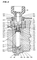
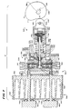
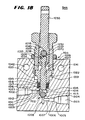
- FIG. 2 there is shown a sectional view of the clipped-together extraction cartridge 26, knob 34 and breech plug 32 replaceably installed in pressure vessel 24 which in turn has previously been permanently force fit into heating block 22.
- the pressure vessel 24 is fabricated of type 303 stainless steel for good machinability and corrosion resistance and has within it a cylindrical central opening sized to receive the extraction cartridge 26, two openings for outlet fittings in its bottom end, an opening in its cylindrical side wall to receive an inlet fitting and an open top with internal threads sized to engage the external threads 188 of the breech plug 32.
- the heating block 22 is fabricated from aluminum for good thermal conductivity and includes a cylindrical opening sized to tightly receive the pressure vessel 24.
- the breech plug 32 and the extraction cartridge assembly 30 are a slip fit within the pressure vessel 24. External threads 188 on breech plug 32 engage in internal threads 200 within pressure vessel 24.
- An annular self-acting high pressure seal 202 cooperates with a sealing surface 186 to seal high pressure supercritical fluid from the atmosphere and an annular low pressure seal 204 spaced from the annular high pressure seal 202 prevents contaminated supercritical fluid in the space between the interior of the pressure vessel 24 and the exterior of the extraction cartridge assembly 30 from getting back to the supercritical fluid supply.
- These two annular seals 202 and 204 form between them a toroidal inlet chamber into which the outlet of the fluid inlet 42 extends to introduce fluid. Contamination may arise from fingerprints or other foreign material on the outside wall of extraction cartridge assembly 30 and the low pressure seal 204 protects against this contamination.
- Seals 202 and 204 are Bal-Seal type 504MB-118-GFP.
- Supercritical fluid is supplied to fluid inlet 42 and circulates in the annular space between high pressure seal 202 and low pressure seal 204, and then follows two paths into the pressure vessel 24 and extraction cartridge 30: one path for purging and one path for extraction.
- An annular spacer 206 within the torroidal opening between seals 202 and 204 has an hour-glass shaped cross section with radial holes through it and distributes incoming supercritical fluid from the inlet of fitting 42 to the opposite side of the spacer 206 from which it flows to passageway 208 drilled in breech plug 32.
- the passageway 208 extends radially from the recess 180 in the breech plug 32 to the annular ring, it provides an open path for fluid between the two regardless of the orientation of passageway 208.
- the passageway 208 opens at an uncontrolled angular location with respect to the inlet fixture 42 (inner side). Fluid flows from one side of the inwardly curved portion of the hour glass shaped spacer 206 that communicates with the outlet of fitting 42 to the other side of the inwardly curved portion and from there to the passageway 208.
- Screwing the breech plug 32 in further after the cartridge and plug assembly 26 has bottomed causes the upper flat annular surface of fitting nipple 176 to bear upon the flat lower surface of a hat-shaped washer 216.
- the hat-shaped washer 216 is residing against the upper surface of the head of a shoulder screw 218 which is threaded into cylindrical hole 222 in breech plug 32.
- the force of the compression spring 201 is enough to provide a low pressure seal between the hat-shaped washer 216 and the upper annular surface 203 of the fitting nipple 176. More importantly, this force also provides a low pressure seal on the mating concical surfaces of the recess 210 of lower cap 144 and the external conical tip 212 of the fitting adapter 214.
- the sealing surface 186 acts as a pilot during the initial part of insertion to insure that the internal threads 188 do not get cross-threaded.
- a taper 189 at the end of the cylindrical sealing surface 186 pilots the breech plug 32 past seals 202 and 204 so that they are not damaged during insertion of the breech plug 32.
- the locations of recess 224, passageway 208, high pressure seal 202 and the engaging threads 188 and 200 are chosen such that if the breech plug 32 is inadvertently removed when the interior of the pressure vessel 24 is pressurized, fluid within the pressure vessel 24 leaks past high pressure seal 202 and runs up the flights of the engaging screw threads 188 and 200, and depressurizes the system while there is still adequate screw engagement to ensure safety at the maximum rated operating pressure.
- the maximum rated operating pressure of the embodiment shown in FIG. 2 is 10,000 psi.
- the maximum operating temperature is 150 degrees Centigrade.
- the equipment need not be designed for operating temperatures above 300 degrees Centigrade and pressure above 30,000 pounds per square inch.
- the fluid passes garter spring 184 and circulates with even circumferential distribution around the outside of top cap 148, the extraction tube 152, and the bottom cap 144.
- the flow is collected in the annular space below the bottom cap 144 and above the bottom 240 of pressure vessel 24 and exits through vent discharge fitting 44, carrying contaminants with it.
- Low pressure seal 204 prevents contaminated fluid from reaching passageway 208.
- a labyrinth seal consisting of the narrow gaps between the major diameter of fitting nipple 176 and the inside diameter 230 of recess 180, and between inside diameter 230 and the outside diameter of the hat-shaped washer 216, prevents contaminants from reaching the space above the hat-shaped washer 216 by diffusion.
- supercritical fluid entering fitting 42 is distributed in the space occupied by spacer ring 206, flows through passageway 208 and flows down the few thousandths of an inch radial gap between the shoulder of shoulder screw 218 and the inside diameter of washer 216.
- the fluid continues to flow down and flows through passageway 250, porous frit 162 and into extraction volume 254 where it passes through material to be extracted.
- Extraction volume 254 is shown sized in FIG. 2 for a 10 cubic centimeter volume to receive sample. After passing the extraction volume fluid, it is exhausted for sample collection through frit 160, passageway 260, fitting adapter 214 and out through fitting 46.
- All tubing, except tubing designated as capillary tubing, in this disclosure is 300 series stainless steel with an outside diameter of 1/16 inch and inside diameter 0.02 inch.
- the heat exchanger 40 actually resides in a longitudinal bore through heating block 22 so that the heat exchanger is at the same temperature as pressure vessel 24 and extraction tube 30. This preheats any fluid flowing into inlet fitting 42 to essentially the same temperature as the extraction cartridge assembly 30. This temperature is above the critical temperature for the fluid. Assuming that the pump 12 is set to produce a constant fluid pressure greater than the critical pressure, fluid entering the pressure vessel 24 will be a supercritical fluid.
- the check valve 60A prevents backflow of supercritical fluid out of the pressure vessel 24 and extraction cartridge 26 of a first channel of a dual channel supercritical extraction system if there is a momentary drop in pressure of the supercritical fluid at the location of the tee 20. Such a pressure fluctuation could occur if the second channel of a dual channel extraction system is suddenly purged while the first channel is extracting. Each channel requires such a check valve.
- contaminated supercritical fluid leaves fitting 44, flows through a tube 62 and enters the inlet fitting 116 of the purge fluid valve 52. Then it exits the outlet fitting 118 and passes through the tube 64 to the coupling 90 (Fig. 1).
- the coupling 90 couples the quartz capillary tube 110 so that contaminated purge gas exits through it.
- the bore of the capillary tube is small enough, such as 75 micrometers, and its length long enough, on the order of a few inches, to provide enough fluid resistance to limit the flow to a convenient rate: for example 5 milliliters per minute with respect to displacement of pump 12, at a pressure of 3,000 psi.
- Pump 12 is a constant pressure pump so this fluid flow does not affect the pressure within pressure vessel 24 once the flow stabilizes.
- the outer end of capillary 110 may be immersed a purge fluid collector 92 (Fig. 1) containing an appropriate solvent 100 such as isopropyl alcohol to serve as a collector. Bubbles through this solvent indicate proper flow and the solvent tends to prevent the end of the capillary tube 110 from being plugged by the exhausted contaminants.
- a solvent is chosen in a manner known in the art to dissolve contaminants so the end of the capillary tube 110 does not plug and so the solvent may later be analyzed if desired to determine whether there was any contaminants on the exterior of the extraction cartridge.
- extractant exits fitting 46 on pressure vessel 24 and passes through tube 66.
- This tubing extends to inlet fitting 120 of extractant valve 50 which has rotary control shaft 126 attached to control knob 132.
- the extractant valve 50 is opened by turning it counterclockwise from its closed position, fluid exits from its fitting 122, through tube 68 to fitting 94.
- Fitting 94 couples to quartz capillary tube 128 or other flow restrictor device.
- Capillary tube 128 has a small enough bore, such as 50 micrometers, and a long enough length, on the order of several inches, to produce a flow rate, relative to the displacement of constant pressure pump 12, of a conveninent amount. For example, this may be two milliliters per minute.
- the end of the capillary tube 128 dips into solvent 104 in the extractant collector 98.
- solvent 104 is under some circumstances used for solvent 104.
- This solvent 104 must be a good solvent for the extractant since it must trap the extractant by dissolving it from the gas bubbling through it and must prevent plugging at the end of the capillary tube 128.
- the solvent 104 is removed after extraction and is analyzed to determine the composition and amount of the extractant. Because of the pressure and temperature drop along the length of capillary 128 (and also capillary 110) fluid entering the capillary as a supercritical fluid (or a liquid if fitting 90 or fitting 94 is not heated) changes to a gas by the time it reaches the far end where it dips into the solvent which is at room temperature.
- the pump 12 is set to the desired pressure and the heater block 22 is set to the desired temperature.
- the bottom cap 144 (FIG. 2) with the frit 160 is screwed onto the bottom of extraction tube 152.
- the internal cavity 158 is then filled or partly filled with sample to be extracted.
- the frit 162 and top cap 174 are then screwed on to the top of extraction tube 152 forming the cartridge and plug assembly 26.
- the cartridge and plug assembly 26 is then clipped into breech plug 32 by shoving the fitting nipple 176 on the extraction cartridge past garter spring 184 located within breech plug 32.
- Knob 70 is set to the vent position closing valve 54 and opening valve 52 (FIG. 1).
- Valve 124 is set to the clockwise closed position.
- the assembled breech plug and extraction cartridge are inserted into preheated pressure vessel 22 and manually screwed with knob 34 into pressure vessel 24 until annular flange 190 contacts the top of pressure vessel 24 (FIG. 2).
- the pressure vessel has been preheated under control of a thermocouple temperature controller to the desired temperature.
- the cartridge and plug assembly 26 within pressure vessel 24 rapidly rises to the required temperature.
- valve knob 70 is rotated to the purge position. In this position, both valves 54 and 52 are open. Since the pump 12 has already been set to the desired fluid pressure, fluid flows through tubes 76, 56, valve 54, tube 58, heat exchanger 40, tube 60, check valves 60A and 60B and inlet fitting 42 into the cavity 180. Since valve 124 is closed, supercritical fluid preheated to the correct temperature by heat exchanger 40, flows past hat-shaped washer 216, fitting nipple 176 and around the outside of cartridge and plug assembly 26. This supercritical fluid dissolves any contaminants on the outside of extraction cartridge assembly 30 and any contaminants inside pressure vessel 24. The hot supercritical fluid also insures that the extraction cartridge assembly 30 is at the proper operating temperature. The supercritical fluid flushes the contaminants from fitting 44, through tube 62, valve 52, tube 64, the fitting 90 and the capillary tube 110.
- control knob 70 is set to the extract position. This sets valves 54 and 52 so that valve 54 is open and valve 52 is closed. Immediately after making this setting, the operator opens valve 124 by rotating knob 132 counterclockwise in the extract direction. Pressurized fluid flows through valve 54 into heat exchanger 40 so that it is at the desired supercritical temperature, and flows into fitting 42. It then flows into cavity 180 and past the annular space between shoulder screw 218 and the inside diameter of hat-shaped washer 216, after which it passes through the interior of fitting nipple 176, through passageway 250 and into the extraction vessel 26. This supercritical fluid flowing through the interior sample cavity 254 of the extraction cartridge extracts analyte from the sample 134 contained within the cavity 254.
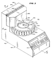
- FIG. 3 there is shown a simplified perspective view of another embodiment 10A of supercritical fluid extraction system having a cabinet 400 containing a drive section in its lower portion (not shown in FIG. 3), an extraction section in the upper portion of the cabinet (not shown in FIG. 3), a sample injection section 406 and a fraction collection section 408.
- the supercritical liquid extraction system 10A is controlled from a panel 410 on the front of the cabinet 400 and the drive section operates the extraction section, the sample injection section 406, and the fraction collection section 408, which cooperate together to extract a plurality of samples sequentially and collect the extractant from the samples in separate containers with minimum intervention by an operator.
- the liquid extraction system in the embodiment 10A operates in a manner similar to that of the embodiment of FIG. 1 but is adapted to cooperate with the novel sample injector and fraction collector. With this arrangement, a series of samples to be extracted are preloaded into a means for holding the samples and the samples are automatically injected one at a time into the extractor. In the extractor, supercritical fluid is supplied to the samples and an extractant is removed from the samples one by one.
- similar parts have the same reference numerals but in the embodiment of FIG. 10A, the numerals include the suffix "A".
- the extractant is supplied to individual containers or individual compartments of one container in a fraction collector.
- a plurality of extractions are performed on a plurality of different preloaded samples without the need for manually loading samples or initiating the flow of the supercritical fluid for each individual sample.
- the samples are automatically mechanically moved one by one into the extractor for extraction instead of being individually physically injected by an operator.
- the cabinet 400 has a lower portion 412 generally shaped as a right regular parallelopiped with an angled control panel 410 and upstanding upper portion 414 which is another right regular parallelopiped extending upwardly to create a profile substantially shaped as an "L" having a common back portion or rear panel 416 which may contain fans and connections for supplementary pumps and the like.
- a fluid fitting 420 extends from one side to permit near supercritical fluids to be introduced into the cabinet 400.
- the L-profiled cabinet 400 has an angled front panel 410 for convenient use of controls and a top surface on the foot of the "L” for manipulation of samples to be injected and extractants that are collected.
- the upper portion 414 includes a hinged front access panel 422 having hinges 426 at its top so that it can be pivoted upwardly. It includes an opening 424 near its bottom to permit the entrance of fraction collector receptacles that are relatively tall. It extends downwardly to a point spaced from the top surface of the lower portion 412 of the cabinet 400 a sufficient distance to permit the entrance of normal receptacles used in the sample injector and the fraction collector.
- the sample injection section 406 includes a sample reel 430 which is formed of upper and lower rotatable plates 432 and 434 spaced vertically from each other and containing holes in the upper plate 432 and openings in the lower plate 434 which receive cylindrical tubular sleeves 436 having vertical longitudinal axes and open ends.
- the upper open end 438 permits samples to be received and to be removed as the sample reel 430 is rotated into the extractor.
- the sample reel 430 may be rotated to move samples one by one into the extractor for processing.
- the sample reel 430 is horizontal and extends into the upper portion 414 of the cabinet 400 and into the extractor assembly with its vertical center of rotation being outside of the upper portion 414 to permit ready access to a number of the sleeves 436 by users and yet to permit sequential rotation by automatic means into the extractor.
- there are 24 sleeves for containing 24 distinctly different samples which can, without human intervention, be moved into the extractor.
- the fraction collection section 408 includes a horizontal fraction collector reel 440 mounted concentrically with the sample reel 430 but having a smaller diameter to be inside the sample reel 430 having a plurality of openings 442 circularly arranged in spaced apart relationship with each other about the periphery of a top plate 446 of the fraction collector reel 440 and having in its center a knob 444 by which the fraction collector reel 440 may be lifted and removed from the cabinet 400.
- the fraction collector reel 440 may be lifted and removed or reinserted after the hinged access panel 422 is pivoted upwardly about the hinges 426.
- the fraction collector reel 440 When the fraction collector reel 440 is in place, it is rotated automatically through the opening 424 into a location in which one or more individual containers 442 may receive extractant.
- the fraction collector reel 440 is moved alternately with the sample reel 430 and independently of it so that, after a sample injection and extraction, one or more of the openings 442 are moved into position to receive the extractant prior to the injection of another sample for extraction.
- the collected extractant may be removed and new sample added during operation of the equipment.
- the receptacles for the fractions and the receptacles for the samples have upward open ends and are mounted with their axes vertical.
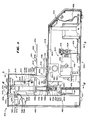
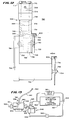
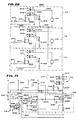
- FIG. 4 there is shown a longitudinal sectional view through lines 4-4 of FIG. 3 showing the cabinet 400, the drive section 402 within the cabinet 400, the extraction section 404, the sample injection section 406 and the fraction collection section 408.
- the drive section 402 includes a control system 450, a sample-and-extractant container reel drive assembly 452, a sample injector drive 454 and a fluid drive or pump 456.
- the control system 450 receives information from the control panel 410 and conveys information to it through a cable 458.
- the sample injection section 406 includes the sample-and-extractant container reel drive assembly 452, the sample reel assembly 430, and a cartridge injector assembly 460.
- the sample-and-extractant container reel drive assembly 452 drives the sample reel assembly 430 to carry a cartridge assembly 30A onto the cartridge injector assembly 460 which lifts it under the control of the sample injector drive 454 upwardly into a pressure vessel 24A for the purpose of extracting a sample within the cartridge assembly 30A.
- the cartridge assembly 30A and the pressure vessel 24A are similar to the cartridge assembly 30 and pressure vessel 24 of the embodiment of FIGS. 1-14 and are only adapted such as by having their top and bottom sides reversed to permit the cartridge assembly 30A to be inserted from the bottom into the pressure vessel 24A and be more easily sealed therein for extraction and removed by gravity after extraction.
- the sample-and-extractant container reel drive assembly 452 includes a central transmission and motors on each side that drive the transmission under the control of the control system 450 to drive either one or both the sample injector reel assembly 430 and the fraction collector reel 440.
- the sample injector reel assembly 430 includes the top plate 432, the bottom plate 434, both of which are rotatable together to carry a plurality of sleeves 436 sequentially, one at a time, into position for the repeated injecting of cartridges one by one into the pressure vessel 24A and the removal of the cartridges from the pressure vessel 24A and the return of them to the reel assembly 430 one by one so that only one cartridge is in the pressure vessel 24A at a time.
- a stationary bottom plate 462 has a hole 464, with the hole being aligned with the open-bottom end of the pressure vessel 24A and the upper end of the cartridge injector assembly 460. Consequently, the cartridge assemblies such as 30A are rotated one by one above the open end 464 in the bottom plate 462 for movement upwardly into the pressure vessel assembly 24A by the cartridge injector assembly 460 under the control of the sample injector drive 454 for extraction of the sample therein.
- a stationary plate 462 holds the cartridge assemblies 30A in place as they are rotated by the upper and lower plates 432 and 434 until they are sequentially brought over the opening 464 through the stationary plate 462 for elevation into the pressure vessel 24A.
- the cartridge injector assembly 460 includes the sample injector drive 454, a pinion 470, a gear 472, a multi-threaded, fast action nut 474, a corresponding screw 476, and piston or plug 32A.
- the pinion 470 is mounted to the output shaft of the drive gear motor 454 and engages the teeth of gear 472.
- the gear 472 is fastened to or integrally formed with the drive nut 474 which, as it rotates, moves the screw 476 upwardly or downwardly.
- the support platform 475, piston or plug 32A and sample container 30A are carried by the top of the screw 476 and are moved upwardly and downwardly.
- Plug 32A carries self-actuated, spring-biased, cylinder seals, such as those made by the Bal-Seal Corporation. These seals provide a high pressure fluid-tight seal between the plug 32A and the inner wall of the pressure vessel 24A.
- the piston or plug 32A is sealable against the walls of the pressure vessel 24A during the extraction process after moving the cartridge assembly 30A upwardly into the pressure vessel 24A, and after extraction, can move the cartridge assembly 30A downwardly back to the sample reel assembly 430 for rotation out of the upper injector housing 414 as a new cartridge is moved into position for injecting into the pressure vessel 24A.
- a bearing mount rotatably supports the nut 474 while maintaining it in the same vertical position so as to move the rapid-advance screw or other screw 476 upwardly and downwardly.
- the plug 32A serves a function similar to the breech plug 32 in the embodiment of FIGS. 1-14 and contains within it an opening supporting a spring 201A and a support block 482 so that the support block 482 is biased inwardly against the cartridge end 148A to move the cartridge 30A into place against fittings for supercritical fluid.
- extracting fluid is applied through the fitting 42A in a manner similar to the embodiment of FIG. 1, so that the extracting fluid flows through one path into the cartridge 30A and through another path over the outside of the cartridge 30A into the fitting 44A and from there to a purge collector or vent.
- the extractant after passing through the cartridge and the sample, exits from a fitting 46A and proceeds to the sample collector in a manner to be described hereinafter.
- the pump 456 includes a pump head and gear box 490 and an electrical motor 492; and (2) the pressure vessel 24A has an aluminum heating block 22A over it, an opening 278A in the aluminum heating block, a rod-shaped heating element 274A in the aperture 278A, the extracting fluid fitting 42A and a heat exchanger 40A entering the aluminum heating block 22A at aperture 270A.
- the motor 492 drives the pump mechanism 490 to pump fluid into the aperture 270A, through the heat exchanger 40A within the aperture 270A, through the connecting tubing 60A and the fitting 42A and into the cartridge 30A and the pressure vessel 24A.
- the aluminum block 22A controls the temperature of the fluid, which may be carbon dioxide or any other useful extracting fluid to keep it above the supercritical temperature for that fluid, and for that purpose, the heating rod 274A within the aperature 278A is used when necessary to heat the aluminum block 22A.
- the fluid which may be carbon dioxide or any other useful extracting fluid to keep it above the supercritical temperature for that fluid, and for that purpose, the heating rod 274A within the aperature 278A is used when necessary to heat the aluminum block 22A.
- the pump 456 may be any suitable pump, but one appropriate pump for carbon dioxide is a highly modified version of the pump used in the Isco model 2350 HPLC Pumping System sold by Isco, Inc., Lincoln, California. However, for best results when using carbon dioxide, the stroke of this pump is modified from ten millimeters to fifteen millimeters and smaller, lower trapped-volume check valves are used. These modifications increase the compression ratio of the pump from 1.64:1 to 2.64:1 and increase the displacement by a multiple of 1.5. Additional changes are the use of: (1) Carpenter Technologies 182FM stainless steel in the pump head, instead of type 316, for better thermal conducting; (2) differently shaped cam; and (3) heavier bearings.
- the fraction collector section 408 includes the fraction collection reel 440, the sample-and-extractant container reel drive assembly 452, a purge fluid outlet system 520 and an extractant fluid outlet system 522.
- the fraction collection reel 440 moves receptacles such as 98A into position within the housing 414 where the extractant fluid outlet system, 522 to be described in greater detail hereinafter, causes fluid from the fitting 46A in the pressure vessel 24A to flow outwardly and into the receptacle 98A after piercing a seal therein.
- the purge fluid system 520 causes purge fluid to flow from the purge fluid fitting 44A to a pressure control unit and finally to an exhaust or collection unit.
- the fraction collection reel 440 To move the collection receptacles 98A into position, the fraction collection reel 440 includes a knob 444, an intermediate plate 448, an upper plate 446, a lower disk plate 530 and a drive rod 532.
- the drive rod 532 rotates within the fixed disk 530 and carries above them the upper and lower plates 446 and 448.
- the upper and lower plates 446 and 448 have aligned circumferentially spaced holes through them, each of which can receive a collection vial such as 98A.
- the lower disk 530 does not have holes and supports the plates as they are moved.
- the knob 444 may be used to lift the fraction collector reel 440 from the center of the sample injector reel 430 after the hinged front access panel 422 has been opened about its hinge 426.
- the sample-and-extractant container reel drive assembly 452 moves the collection vials one by one inside the upper portion of the housing 414 to receive extractant.
- One or more such vessels 98A may be moved in place each time a sample cartridge 30A is extracted so that the receptacles 98A are moved alternatively with the sample cartridges 30A, although several receptacles 98A may be moved in the time between moving one of the sample cartridges 30A into a pressure vessel 24A and the time the sample cartridge is removed from the pressure vessel 24A.
- the extractant passes through fitting 46A and into the fraction collector receptacles 98A in a manner to be described hereinafter.
- the purge fitting 44A communicates with the extraction volume in the cartridge 30A and is connected to a Tee-joint tube 542 through tubing 62A.
- a second arm of the Tee-joint tube 542 is connected to an over-pressure safety diaphram 540 calibrated to burst at 15,000 pounds per square inch. This is an excess of the maximum rated working pressure of 10,000 pounds per square inch for pressure vessel 24A.
- the remaining arm of the Tee-joint tube 542 is connected to the purge valve 52A.
- the other side of the purge valve 52A is connected to the first side of a second Tee-joint tube 544 through the tube 64A.
- the second side of the Tee-joint tube 544 is connected to an exterior vent port 546 through a tube 548.
- the third arm of the Tee-joint tube 544 is connected to the exhaust tube 110A which vents the fraction collection vial 98A.
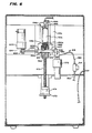
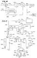
- FIG. 5 there is shown a simplified sectional elevational view of the embodiment 10A of supercritical fluid extractor taken through lines 5-5 of FIG. 4 having the sample-and-extractant container reel drive assembly 452, the pump 456 and the extractant fluid outlet system 522.
- the sample-and-extractant container reel drive assembly 452 may selectively move either the sample reel 430 or the fraction collection reel 440 under the control of the controller 450 (FIG. 4).
- the sample-and-extractant container reel drive assembly 452 includes a fraction collection spindle 532, a tubular shaft 580, a bevel gear 582, a bevel gear 584 and a gear motor 586.
- the controller 450 controls the gear motor 586 to rotate the fraction collection reel 440.
- the spindle 532 is held by the tubular shaft 580.
- the bevel gear 582 is fastened at the end of the spindle 532 and meshes with the bevel gear 584 on gear motor 586.
- the controller 450 causes the motor 586 to rotate its output shaft so as to drive the collection reel 440 (FIGS. 15 and 16) and not the sample injector reel 430 (FIGS. 3 and 4).
- the sample-and-extractant container reel drive assembly 452 includes the tubular shaft 580 supported by bearing block 590, fraction collection spindle 532, bevel gear 588, bevel gear 592 and gear motor 594.
- the controller 450 actuates gear motor 594 to cause the bevel gear 592 to rotate.
- the bevel gear 592 meshes with the bevel gear 588 which is attached to the bottom end of the fraction collection spindle 532.
- the extractant fluid outlet system 522 includes a gear motor 552, a pinion 554, a gear 556, a lead screw 558, an arm 560, and a restrictor tube 66A.
- the vials 98A have a seal 550 over the top, which seal can be pierced.
- the controller 450 starts the gear motor 552 which rotates its pinion 554 which is in engagement with the gear 556.
- the pinion 554 rotates the gear 556, which engages and is fastened to the rotating lead screw 558.
- the arm 560 is mounted for movement by the lead screw 558 and lowers it into a position where the restrictor tube 66A pierces the cap 550 on the collection vial 98A and moves its tip below the surface 564 of the collection fluid within the vial 98A.
- exhaust is removed from the tube through an exhaust tube 110A (FIG. 4 in addition to FIG. 5).
- extractant flows through the fitting 46A (FIG. 4) from the sample cartridge 30A (FIG. 4) through the tubing 522 (FIG. 4), the valve 50A and the restrictor tube 66A. Extractant residing in bubbles from the tube are captured through trapping fluid 104A whereby extractant is trapped in the trapping fluid 104 in the vial 98A and extracting fluid passes out through the exhaust tube 110A, Tee-joint tube 544 (FIG. 4), tube 66A and exhaust port 546 (FIG. 4). After collection of the extractant, the motor 552 moves in the reverse direction and raises arm 560 which removes the restrictor tube 66A and exhaust tube 110A from the vial 98A.
- both the pump head 490 and incoming fluid line are preferably cooled. In the preferred embodiment, they are cooled thermoelectrically (Peltier effect).
- the pump head 490, the inlet check valve housing 494 are formed of Carpenter 182FM stainless steel rather than type 316 stainless steel to increase their thermal conductivity.
- the pump drive motor 492 (FIG. 4) drives a cam within cam housing 495 through appropriate gear train within the gear housing 496.
- the rotating cam within the cam housing 495 operates a pump plunger which cooperates with the pump head 490A (FIG. 5) to draw liquid carbon dioxide through inlet check valve assembly 494 and discharge it through outlet check valve assembly 436.
- the Peltier cooling plate 500 is mounted to the flat face of the pump head 490A (FIG. 5) with cooling fins 502 mounted for good thermal contact to the opposite side of the Peltier cooling plate 500.
- Peltier cooling plate 500 When an electric current is passed in the proper direction through the Peltier cooling plate 500, heat is withdrawn from the pump head 490A (FIG. 5) and rejected into the cooling fins 502. A fan 504 driven by an electric motor 493 (FIG. 5) withdraws heat from the fins 502. Another Peltier-effect cooled heat exchanger is also utilized in the inlet line.
- a tachometer wheel 505 is mounted to the shaft of motor 492 (FIG. 4) with a photoelectric tachometer sensor 510 mounted to provide signals reading indicia on the wheel.
- the signals from the photoelectric tachometer 510 indicate the speed of motor 492 and thus the pumping speed of pump 456. These signals are compared in the controller 450 and utilized to control the speed of the motor 492.
- a pressure transducer 514 (FIG. 6) generates a signal indicating the pressure. This signal is used as a feedback signal to control the pumping speed.
- This structure is provided by existing pumps such as the Isco model 260D pump.
- FIG. 6 there is shown a sectional view, partly simplified, taken through lines 6-6 of FIG. 4 having a locking mechanism 614 for locking plug 32A into the pressure vessel 24A and a control mechanism 616 for controlling the extraction fluid.
- the locking mechanism 614 includes a gear motor 600, a pinion 602, a rack 604, a locking pin 606, a hole 609 in the pressure vessel 24A and a hole 610 in the piston or end piece or breach plug 32A and a hole 612 through the other side of the pressure vessel 24A.
- a yoke of the type conventionally used as a Winchester 94 rifle locking mechanism advantageously may be used.
- This type of locking mechanism is a yoke mounted to a pinion 602 and rack 604 as shown in FIG. 6.
- a plate with a slot cut out of it to form a yoke is moved by the rack and pinion to pass under the plug 32A to hold it against pressure and provide strong support therewith by further engaging slots in the pressure vessel 24A.
- the aforementioned slot in the plate provides clearance for the screw 476.
- the gear motor 600 is caused by the control system 450 (FIG. 4) to drive locking pin 606 through the opening 609 in the pressure vessel 24A, through the opening 610 in the piston 32A and through the opening 612 in the pressure vessel 24A by rotating the pinion 602 to drive the rack 604 that carries the locking pin 606, thus locking the cartridge 30A (FIG. 4) in place within the pressure vessel 24A.
- the control mechanism for extracting fluid includes the gear motor 570 and valve 54A that is connected at one end to the conduit 58A that extends from line 512 and pressure transducer 514 to the conduit 58 which passes into the heat exchanger 40 (FIG. 1).
- the gear motor 570 under the control of the control system 450 opens the valve 54A to permit the flow of extracting fluid into the cartridge 30A and pressure vessel 24A during an extraction operation. It also rotates in the opposite direction after extraction is complete to close the valve 54A.
- the sample cartridge 30A (FIG. 4) is composed of a tubular sleeve or body portion 140A (FIG. 4) and end pieces 144AA (Fig. 4) and 464A (Fig. 4).
- the end pieces 144A and 464A are made of stainless steel or an inert plastic and carry a stainless steel frit or filter disk centered in the interior of each.
- the flat, narrowed ends of the tubular sleeve 140A seal against PTFE washers around the frits which seal against the end pieces at the location between the diameters of the filter disks and the inside diameters of the end pieces 144A or 464A respectively.
- a cooled pumping unit having a cylindrical pumphead block 300, a piston drive assembly 302, a piston 304, a chamber 336, a cooling assembly 306, and a heat exchanger 763 for transfering heat from the pumphead block 300 to the cooling assembly 306, connected together to pump fluid while cooling the fluid and pump with air-thermoelectric cooling.
- the heat exchanger 762 (FIG. 10) for transferring heat from the fluid into the cooling assembly is not shown in FIG. 7 but is shown in FIGS. 10 and 11. Fluid volume is measured by pressure and movement of the piston 304 within the chamber 336.
- the cooling assembly 306 and the heat exchangers 762 and 763 do not use liquid cooling but the pumping system is cooled entirely by air and not by a liquid coolant.
- the cylindrical pumphead block 300 includes threaded recesses for receiving a generally cylindrical fluid outlet check valve 308 and fluid inlet valve 310.
- the fluid outlet check valve 308 incorporates: (1) a threaded recess 312 for a conventional fluid coupling fitting; (2) ball check valve elements 314 and 316; (3) valve seats 318 and 319; (4) the cylindrical passageway 330.
- the cylindrical passageway 330 communicates between the check valve element 314 and the pumping chamber 336 and contains fluid in contact with the fluid in the pumping chamber 336.
- the valve elements 314 and 316 cooperate with valve seats 318 and 319 respectively in a manner known in the art to form a conventional dual-ball check valve assembly that blocks the flow of liquid into the chamber 336 and permits flow from the chamber 336 to the pump outlet.
- the fluid inlet valve 310 incorporates: (1) a threaded recess 320 for receiving a conventional fluid coupling fitting; (2) check valve ball elements 322 and 324; (3) valve seats 326 and 328; and (4) the cylindrical passageway 334.
- the check valve ball elements 322 and 324 cooperate with valve seats 326 and 328 in a manner known in the art to form a conventional dual-ball check valve assembly controlling the flow of liquid into the chamber 336 and blocking flow of fluid from the chamber 336.
- the cylindrical passageway 334 communicates between the check valve element 322 and the pumping chamber 336 and contains fluid in contact with the fluid in the pumping chamber 336.
- the diameter of the fluid passageways 330 and 334, the annular volume between the piston 336 and the bore 370, and the interval volume of the seal 356 are sufficiently small to restrict the trapped liquid to no more than 0.9 times the displacement and to restrict the compression ratio to no less than 2.1:1.
- the passage 334 is only one millimeter in diameter and the passage 330 is even somewhat smaller.
- a high compression ratio (ratio of volume before compression to volume after compression by the pump) is especially advantagous for pumping very compressible liquids such as liquid carbon dioxide because the high compression ratio tends to quickly discharge the compression-heated fluid before it heats the pump head 300 and also improves the volumetric efficiency which is otherwise degraded by compression of the fluid during the compression/delivery stroke.
- Volumetric efficiency is defined by the amount pumped per stroke divided by the displacement. Higher volumetric efficiency results in a higher maximum flow rate. Compression ratio is less important to HPLC pumps because of the lower compression ratio and have a reason for needing larger inlet fluid passageways. HPLC pumps must have larger inlet fluid passageways because of cavitation problems.
- the check valve balls 314, 316, 322 and 324 are preferably spheres made of synthetic ruby and the valve seats 318, 319, 326 and 328 are made of synthetic sapphire.
- the pumphead block 300 is made of stainless steel, preferably Carpenter type 182FM stainless steel because of its relatively high thermal conductivity (for a stainless steel), its good corrosion resistance and ease of machineability. In those cases where the requirement of ease of machineability is low, half-hard nickle may be used because of the superior thermal conductivity of half-hard nickle.
- the piston drive assembly 302 includes a drive cam 338, a roller cam follower 342, a ferrule-anvil combination 352 and 350, a compression spring 384, a yoke 346 and a tubular slide 348 as its principal parts.
- the ferrule is attached by injection-molding onto the right end of the synthetic sapphire displacement rod, or piston rod 304.
- the yoke 346 is an integral part of the tubular slide 348 which supports the anvil 350.
- a circumferential groove 358 ground into the piston rod 304 insures a firm mechanical coupling between ferrule 352 and rod 304.
- the ferrule 352 is made of the same material as the anvil 350.
- the anvil can be made of polished stainless steel.
- the former material is a low coefficient friction plastic having relatively high compressive strength and relatively low compressive modulus. It is injection molded to form the ferrule 352 and the anvil 350. The ferrule 352 is molded onto the rod 304.
- the drive cam 338 drives the cam follower 342, which in turn drives the ferrule 352 downwardly against the pressure of the compression spring 384.
- the rod or plunger 304 moves with the ferrule 352 to reciprocate in the chamber 336 to pump fluid through the outlet valve 308.
- the roller cam follower 342 is mounted to rotate on a trunnion 344 mounted in the yoke 346 mounted to the anvil 350 for rotation therewith.
- the reciprocating sapphire piston rod 304 is shown in its maximum retracted position in FIG. 7.
- Rotation of drive cam 338 in the direction indicated by the arrow 341 forces the roller cam follower 342 mounted on trunnion 344 to move the yoke 346 in a direction that expells fluid which in the preferred embodiment is toward the inlet and outlet shown to the left in FIG. 7.
- the surface of the ferrule 352 that is engaged by the anvil 350 during a piston stroke is a spherical surface having a radius large enough so that, in case of misalignment with respect to anvil 350, the line of contact and direction of force between the spherical surface and the anvil does not have a significantly large component perpendicular to the axis of the piston rod 304.
- the piston 304 is not forced out of alignment during a piston stroke. This reduces wear in the tubular bearing 354 and the seal 356 and prevents the rod 304 from breaking.
- anvil 350 and ferrule 352 are in hertzian contact with each other.
- the amount of depression of the spherical surface of the ferrule 352 and the forces lateral to the radius of the spherical surface that is normal to the anvil 350 is related to the compressive modulus of the ferrule material, the diameter of the spherical surface and the normal force.
- the relatively high strength of the material used General Electric bearing grade polyetherimide resin "Ultem 4001", of 21,200 psi compressive strength and relatively low compressive modulus of 450,000 psi, produces a hertzian force at maximum operating pressure of only half of the compressive yield strength of ferrule 352 and anvil 350.
- the inlet fluid is under pressure that forces it into the pump chamber 356.
- the piston rod 304 fits within and is principally guided by a first bearing sleeve 364.
- the sleeve 364 is force-fit into cylindrical recess 366 formed within the pumphead 300 with a larger diameter than the diameter of the pump chamber 336 and joining the walls 370 of the pump chamber 336 at a shoulder.
- the inside diameter (walls 370) of the pump chamber 336 is slightly larger than the inside diameter 368 of sleeve 364 so piston 304 does not come in contact with the inside diameter of chamber 336.
- first sleeve 364 is an almost-snug, slip fit with respect to piston 304.
- the diametrical clearance is only about 0.001 inch and therefore, the sleeve acts as a linear bearing which closely and accurately guides the reciprocating motion of piston 304.
- Helical-toroidal spring-loaded self acting seal 356 is located in the hole 372 bored in pumphead block 300. The spring in the spring-loaded seal 356 improves the reliability of the seal.
- the seal used is a Bal-Seal type #X41641. The seal is backed up by ring 374 made of unmodified polyetheretherketone.
- the bearing sleeve 364 is preferably made of a material softer than that of stainless steel pumphead 300. It should have a suitable spectrum of chemical resistance, a low coefficient of friction against piston 304 and should be dimensionally stable. It is believed that the suitable bearing materials should have a yield strength between 5,000 to 20,000 psi and adequate deformability.
- Suitable materials if the pump is not intended to be used to pump fluids containing acid in the presence of water are No. 1 babbitt (tin with 4.5% copper and 4.5% antimony), or an alloy of tin containing 10% gold for hardening and increased corrosion resistance.
- the latter alloy has a corrosion resistance which is about twice as good as that of No. 1 babbitt.
- No. 1 babbitt in turn, has corrosion resistance superior to that of any of the other babbitts.
- Neither of these materials have corrosion resistance as good as the stainless steel pumphead block 300.
- Soft-metal bearing materials which have at least as good a corrosion resistance as the other wetted metals within the pump are gold or pure palladium annealed to a yield strength on the order of 6,000 to 10,000 psi.
- the materials for the bearing sleeve 364 either do not have an extremely broad spectrum of corrosion resistance (the tin alloys) or they are expensive (the precious metals; however palladium is not excessively expensive). Accordingly, the specific material is selected as trade-off between cost, the use of a bearing sleeve of a soft metallic material and corrosion resistance depending on the intended use of the pump.
- Metals generally have high thermal conductivities and it is desirable to efficiently remove the heat of compression of a compressible fluid being pumped at a temperature close to its supercritical temperature. If sufficient heat of compression is not removed; the fluid gets too warm, its density drops rapidly and its compressibility increases rapidly, making it difficult or impossible to produce a reasonable mass flow with the pump.
- the metallic wall 370 is in contact with about half the maximum volume of fluid within the pumping chamber 336 and serves on its own for a significant amount of heat removal within the pump chamber. Therefore, it is possible to use a low thermal conductivity material for the bearing sleeve 364 with a moderate degradation of performance. Suggested non-metallic materials for this sleeve include DuPont "PFA” perfluorinated polyether plastic or ICI “PEEK” plastic.
- the pumphead block 300 is nutted tightly onto type 303 stainless steel studs 715 and 717 (FIG. 12) through support block 376 and into 203EZ (Ryerson) stainless steel guide sleeve 378.
- Support block 376 is injection molded from ICI type 450CA30 PEEK (carbon fiber reinforced polyetheretherketone).
- the 303 stainless studs are not shown since they are out of the plane of the section shown in FIG. 7. They are indicated as 715 and 717 in FIG. 12. Their nuts are recessed into pumphead 300.
- the support block 376 has relatively low thermal conductivity and thermally insulates the pumphead block 300 from the support sleeve 378.
- a recess 380 within support block 376 loosely supports tubular bearing 354 in the diametrical direction.
- Bearing 354 is preferably made of a low friction, strong plastic such as ICI type 450CF30 grade of PEEK.
- the bottom of recess 380 is in light face-to-face contact with the right end of tubular bearing 354, which tightly compresses it against backup disk 374 when the type 303 stainless mounting bolts (FIG. 12) are tightened during assembly.
- the sapphire piston 304 In operation, as the cam 338 rotates on shaft 382, the sapphire piston 304 is urged to the left until it reaches its maximum leftward excursion with its end fairly close to the left end of the pumping chamber 336.
- the cam 338 continues to rotate past the maximum and then compression spring 384 and pressure within the chamber 336 urge piston 304 to the right with needle-bearing roller cam follower 342 remaining in contact with the periphery of the cam 338.
- This reciprocating motion of the piston rod 304 continues and provides a pumping action for fluid entering the inlet fitting at 320 and exiting the fitting at 312 in the manner usual with reciprocating fluid pumps.
- the diameter of the piston 304 is 1/8 inch and its longitudinal motion during one rotation of cam 338 is 15 millimeters. This results in a displacement of 0.12 milliliter per stroke of the plunger 304.
- thermoelectric cooling element 386 which removes heat from aluminum heat coupling spreader plate 390 which in turn is in close thermal contact with pumphead block 300.
- Melcor type CP1.0-127-05L thermoelectric elements and Melcor type CP1.4-127-045L thermoelectric elements provide satisfactory results, with Melcor type CP1.4-127-045L producing the better results of the two elements.
- the heat coupling spreader plate 390 is desirable since the thermoelectric element 386 is square and its corners would protrude past the outside diameter of pumphead block 300.
- thermoelectric cooling element 386 The heat rejected from pumphead 300 and spreading plate 390 to the thermoelectric cooling element 386, plus the electric resistive heat generated within the cooling element 386 is connected to finned aluminum extrusion 392 which provides for heat removal.
- the heat removal extrusion 392 is surrounded sheet metal shroud 394 defining multiple cooling air passages such as 396 for forced air cooling to be described later. No liquid cooling is used in any form.
- Stepped screws 398 and 401 thread into the pumphead block 300 at locations 711 and 713.
- the steps of the screws force heat spreader plate 390 against the pumphead 300.
- the stepped screws respectively have hand knobs 403 and 405 and compression wave washers 717 and 715 which force shroud 394 of cooling assembly 306 to the right, pressing finned aluminum extrusion 392 into good thermal contact with thermoelectric element 386.
- the cooling assembly 306 may be removed from the pumphead 300 by unscrewing screws 398 and 401 with knobs 403 and 405, releasing the shroud 394 and fins 392, also releasing thermoelectric element 386 and heat spreader plate 390, which have been sandwiched between the finned extrusion 392 and pumphead 300.
- This provides access to the two stainless steel screws 715 and 717 (FIG. 12), the heads of which are recessed into pumphead block 300. These screws hold the pumphead to the spacer block 376 to the mounting sleeve 378. The removal of these screws provides for removal of pumphead block 300 so that seal 356 can be replaced if necessary.
- cooling assembly 306 and heat exchanger 763 adds to the difficulty of getting access to seal 356 for its replacement. To compensate for this, it is desirable to increase the life of the seal so that replacement is less frequent. To this end, bearing sleeve 364 keeps the piston 304 centered very accurately within the center of seal 356, thus prolonging the life of the seal far past what is usual with this type of pump. This collinearity minimizes the radial stress on the seal and provides a remarkably longer seal life.
- the following three steps are initially taken in manufacturing the pumphead 300, which three steps are: (1) the bores 370 and 366 are made in pumphead block 300; (2) a solid rod of the material selected for the bearing sleeve 364 is turned to an outside diameter which forms a good force fit in bore 366; and (3) the sleeve 364 is then force fitted into bore 366.
- the pumphead block 300 is chucked in an accurate lathe and the recess or gland 366 for seal 356 is turned; and (2) without disturbing the lathe setup any more than is necessary to carefully change boring tools, the inside bore 368 of bearing sleeve 364 is bored, leaving the center of gland 366 and the center of bore 368 of sleeve 364 collinear.
- optical flag 722 (FIG. 12) and sensor 724 (FIG. 12) in cooperation with the pump controller, provide push-button capability for the user to operate the motor drive to rotate the cam 338 under program or computer control to a position that moves the piston 304 only so far out that it will fill about half or a third of the length of sleeve 364 when the pumphead block 300 is assembled onto support block 376 and guide sleeve 378. It is undesirable at this time for the plunger 304 to move further out, as this unnecessarily subjects it to increased chance of breakage when the pumphead is put onto the plunger.
- second bearing sleeve 354 becomes radially located and locked in place by compressive forces, such that its center axis is collinear with the center axes of first bearing sleeve 364 and rod 304.
- the rod 304 is supported on both sides of the seal 356 by first and second bearing sleeves 364 and 354.
- the axis of rod 304, the axis of the bore in first sleeve 364, the axis of the seal 356 and the axis of the bore of second sleeve 354 are all collinear with respect to each other.
- the resulting accurate and robust collinear alignment of rod 304 with respect to seal 356 provides substantially and reliably increased seal life and there is negligible sidewise or misalignment wear of the seal.
- the piston rod 304 is constrained to operate with close collinearity with the center axis of the pump chamber 336 since the bearing sleeve 364 is immediately adjacent and in the same block of metal.
- the pump chamber wall 370 of chamber 336 does not need to have an internal diameter which is much greater than the diameter of the piston 304, decreasing the unswept volume in the pumphead. It increases the compression ratio to 2.64 to 1, an amount which compares well to an embodiment wherein the spring in the seal 356 of this application is replaced with a solid plastic ring.
- the resulting high compression ratio is needed to provide the high volumetric efficiency required for high flow rate capability when pumping very compressible liquids to a high pressure.
- the seal, sleeve bearing and plunger are located or imbedded within the pumphead rather than being located behind the pumphead as in some other pumps, there is no risk of the plunger running into the walls of the pumping chamber such as in the vicinity of the fluid passages 330 and 334 leading to the check valves and becomming chipped if the diameter 370 of the pump chamber is made small enough to obtain a good compression ratio. If the plunger were to become chipped, the plunger or the chips themselves could then destroy the seal, thus defeating the effort to prolong seal life by providing coaxiality of the plunger with respect to the seal.
- the maximum reverse torque due to depressurization of the fluid in the pump chamber 336 (FIG. 1), as seen by the motor 726 (FIG. 12) or the cam shaft 382 is made substantially equal to the maximum torque during delivery at maximum pressure. This minimizes operating noise and maximizes reliability. This is an important factor for pumps which pump prepressurized and compressible liquid, as is the case with pumps which pump liquids near their critical points, and also generally as pumps for supercritical fluid supply. It is important because of the high stored energy of compression which is not the case with high performance liquid chromatography pumps.
- FIGS. 8 and 9 there are shown two versions 730 of the cam 338 and two versions 728 of the cam-operated plunger displacement curve 736.
- the two version of the cam 338 shown at 730 differ from each other by the portions of the outline 732 and 734.
- the version with the shape shown at 732 is identical to the cam 338 in FIG. 7.
- the version with shape 734 has a shape similar to a conventional fast-refill HPLC pump cam.
- FIG. 9 there is shown a development or cam follower displacement profile 736 for a 0.75 inch cam follower indicating linear movement of cam follower 342 (FIG. 7) and piston 304 (FIG. 7) corresponding to one revolution of the cam.
- a 0.875 inch diameter cam follower has longer life and the difference in displacement profile is negligible.
- a comparison of the displacement profile of a HPLC cam with the cam 338 is shown at 728.
- the curve labeled 738 corresponds to cam surface 732 of cam 338 in FIG. 7 and the curve labeled 740 corresponds to a conventional fast-refill HPLC pump cam; cam surface 734 of cam 338.
- the HPLC-style cam (curve 740) produces a peak reverse torque of about twice the delivery torque at a pressure of 7500 psi.
- the cam 338 represented by development 738 produces a peak reverse torque equal to that of the delivery torque. This is accomplished without decreasing the time of the forward stroke (delivery direction) or increasing the time of the reverse stroke ( i.e. depressurization and refill).
- Position A on the cam 338 represents maximum radius of the cam or the top dead center (extended) position of piston 304.
- the point on the cam at which depressurization ends and refill of the pump chamber 336 starts is indicated as position C.
- the minimum radius of the cam is indicated as position E and corresponds to maximum volume in the pumping chamber 336 and maximum withdrawal of the piston 304.
- Positions A, C, D and E respectively correspond to rotational positions of cam 338 such that positions A, C, D and E are in contact with cam follower 342 and also relate to the corresponding position on the cam development 736 so that position E' occurs every 360 degrees of rotation, as better shown in the development 736 (FIG. 9) between E' and E.
- a first part of surface E'-A is the repressurization surface.
- the remaining (second) part of surface E'-A is the delivery surface.
- the surface near and on each side of position A is the transition surface.
- Surface A-C is the depressurization surface and surface C-E is the refill surface.
- Reverse torque reflected on the cam 338 by cam follower 342 is controlled to a value nearly equal to the delivery torque at cam positions extending from position A to position C.
- the starting slope of displacement after top dead center velocity of the cam follower 342 and therefore the piston 304 (after position A) should be equal and opposite to the displacement slope produced by the linear spiral contour of the cam before top dead center of the cam (before position A).
- the delivery surface displacement slope decreases to zero as it approaches position A.
- the displacement slope of the depressurization surface is zero at position A and then its magnitude increases to the negative of the delivery displacement slope.
- Position C corresponds to depressurization of the pump chamber to the supply pressure.
- the compression is about 1.25. This corresponds to an increase in pump chamber volume of 1.25 x the dead volume.
- the displacement rate or plunger velocity with respect to cam rotation should accelerate continuously as cam rotation increases from position A to position C. Torque on the cam shaft is proportional to the displacement slope times the pressure on the piston 304. Therefore, torque on the cam shaft from position A to position C is kept constant if the slope of the displacement is proportional to the reciprocal of the pressure on the piston 304.
- the pump chamber refills with supply liquid between positions C and E.
- the acceleration be small (nearly constant displacement velocity) as this is an efficient condition for receiving supply fluid with minimal pressure drop and minimal chance of vaporization.
- Such a relatively linear region is generally indicated as position D.
- the cam and the electric drive motor are permitted to passively overspeed during the reverse-torque interval of depressurization and refill of the pump chamber. This provides: (1) small but beneficial increase in the maximum pumping rate at high delivery pressures; and (2) simplifies the circuitry for the motor drive because the motor speed does not have to be controlled under reverse torque conditions.
- the servo loop is used to control the motor speed during fluid delivery and operates similarly to that disclosed in co-pending U.S. patent application serial number 07/843,624; MULTIPLE SOLVENT DELIVERY SYSTEM, Daniel G. Jameson, et al.
- a motor drive system may be used in which each stroke of the reciprocating pump is controlled in a manner analogous to that of each stroke of a syringe pump in U.S.
- the displacement curve just after position A has a shorter (usually less than half) radius of curvature than the displacement curve just before position E.
- the displacement curve after position A has a short radius to quickly traverse through depressurization and start the refill quickly so that the time for the refill period is relatively long and gentle.
- gentle refill is necessary to prevent cavitation in the pump chamber as the incoming fluid is only at atmospheric pressure so the onset of cavitation inside the pumphead may be at a pressure of only 10 psi less than atmospheric. This pressure drop can readily be exceeded due to viscous and inertial fluid forces in the inlet valve and inlet line if the inlet stroke is too violent. Cavitation causes an unreliable or varying flow.
- the pumping system 12 is supplied with a high pressure liquid such as carbon dioxide at 22 o C, which is pressurized by its own vapor pressure of about 870 psi and thus is less susceptible to cavitation.
- the pump is cooled below 16 o C, which reflects a vapor pressure that is at least 100 psi lower. This is about 10 times the suction pressure available to an HPLC pump.
- the cam of a typical HPLC pump causes a gentle (large radius of curvature of displacement) deceleration and a lengthy dwell at nearly zero velocity to allow time for the inlet check valve 310 (FIG. 7) to close.
- This is necessary because the viscosity of HPLC mobile phases typically are ten times the viscosity of liquid carbon dioxide so the ball in the HPLC pump check valve falls closed more slowly.
- the depressurization rate of curvature should be larger than the radius of curvature at the end of the refill period, and preferably at least twice as large.
- the depressurization displacement from A to C on curve 738 should require at least 1.5 times the cam rotation as the same displacement on curve 740.
- Curve 740 corresponds to the displacement of an ordinary single piston HPLC pump such as an Isco model 2350.
- the average displacement slope is at least 20% greater than that of such an HPLC pump.
- table 1 provides the preferred cam follower and plunger displacement rates or slopes with respect to cam rotation for plunger positions corresponding to the top dead center position through the position at which depressurization ceases and inspiration of new liquid starts.
- the preferred displacement slope shown in Table 1 is obtained from curve 738 (FIG. 9) as follows: (1) row 1 - 7500 divided by 7500 equals 1; (2) row 2 - 7500 divided by 4460 equals 1.68; (3) row 3 - 7500 divided by 2400 equals 3.12; (4) row 4 - 7500 divided by 1350 equals 5.56; and (5) row 5 - 7500 divided by 870 equals 8.62.
- FIG. 10 there is shown an air-cooled inlet fluid heat exchanger 762 similar to the heat exchanger 763 (FIG. 7) for the pumphead and the cooling assembly 306.
- the heat exchanger 762 includes a spiral coil 742, an aluminum disk 744 and aluminum disk 746 and a thermoelectric cooling element 754.
- the thermoelectric cooling element 754 pre-cools fluid entering the spiral coil 742 through tubing 770 connected to the coil 742 before the fluid reaches the inlet valve fitting 310 of pumping unit 12 (FIG. 7) through tubing 772 that connects the inlet valve fitting 310 (FIG. 7) to the coil 742.
- the spiral coil 742 has 0.06 inch outside diameter by 0.04 inch inside diameter and is formed of stainless steel tubing sandwiched between aluminum disks 744 and 746. A bore of 0.04 inch is unusually large for this size tubing.
- the spiral coil 742 is in close thermal contact with disks 744 and 746 because of thermally conducting compound packed in the interstitial spaces such as indicated at 748.
- a screw 750 compresses aluminum disks 744 and 746 together, but a heat-conducting aluminum spacer 752 prevents serious flattening of spirally wound tubing 742.
- thermoelectric cooling element 754 is in good thermal contact with finned aluminum extrusion 392.
- the finned aluminum extrusion 392 is enclosed by sheet metal shroud 394 which defines forced air cooling passages between the fins such as 396.
- Four screws 756A-756D (only 756B and 756D being shown in FIG. 10) compress low thermal conductivity plastic clamping members 758A-758D (only 758B and 758D being shown in FIG. 10) against disk 746 by means of clamping force supplied by screws 756A through 756D and spring washers 760A-760D (only washers 760B and 760D being shown in FIG. 10) under the heads of these screws.
- thermoelectric cooler 754 The screws are threaded into the finned extrusion 392 and tightened sufficiently so that thermal contact on both sides of thermoelectric cooler 754 is obtained.
- the screws 756B and 756D, spring washers 760B and 760D, and clamping members 758B and 758D appear in FIG. 10. The other two sets are out of the plane of the section and do not appear on this figure.
- thermoelectric cooling element 754 sandwich thermoelectric cooling element 754 against finned aluminum extrusion 392 because disks 744 and 746 have four-point spring loaded clamping. Passing a current through thermoelectric element 754 causes the side of thermoelectric element 754 that is adjacent to disk 744 to draw heat from disk 744 thereby cooling it and cooling the spiral coil of tubing 742 and cooling the contents of the tubing within this spiral coil. Heat absorbed from aluminum disk 744 and electrical heat generated due to electrical resistance of the thermal elements within thermoelectric cooling unit 754 is rejected to finned aluminum extrusion 392. The heat is removed from finned extrusion 392 by air flow through the cooling passages, one of which is labeled 396, such air flow being in the direction into the plane of the paper. Note that liquid cooling is not used in any form.
- the cooled length of the spiral wound coil of tubing 742 within heat exchanger 762 is 75 inches. With the tubing's internal diameter of 0.04 inch, this results in a heat exchanger volume of 1.5 milliliters.
- the volume of the heat exchanger should not be much less than twice the displacement of the pump 12, or largely uncooled liquid will shoot rapidly through the heat exchanger without adequate cooling during the inlet stroke of the pump. This makes the heat exchanger ineffective.
- the 1.5 milliliter heat exchanger volume is greater than ten times the 0.12 milliliter displacement of the pump.
- the length to diameter ratio of the wetted surface of the heat exchanger as described in the preferred embodiment is 1875 to 1. This provides a large contact area-to-volume ratio which efficiently cools the liquid, e.g. carbon dioxide, being pumped.
- the length to diameter ratio should be at least 50 to 1.
- Non-circular cross section heat exchangers should have a surface to volume ratio at least equal to that of a tube with a 50 to 1 length to diameter ratio.
- FIG. 11 there is shown a pumping system 1100 with pumphead block 300 (rest of pump not shown in FIG. 11) and the in-line heat exchanger 762 mounted to cooling assembly 306.
- a shrouded (box type) propeller fan 764 pulls outside air into the air passages 396 (FIGS. 7 and 10) of finned aluminum extrusion 392 as shown at 766.
- the fan 764 may be a Nidec #A30108 which produces an air flow of about 95 cfm at a static pressure of 0.05 inch of water.
- the air exits the passages 396 and is exhausted by the fan shown by the arrows 768.
- This in cooperation with an electric current passing through thermoelectric cooling elements 386 (FIG. 7) and 754 (FIG. 10), cools the in-line heat exchanger 762 and the pumphead block 300.
- tubing 770 In operation, liquid near its supercritical point enters the heat exchanger 762 through tubing 770, is cooled in its inward spiral passage through spiral coil 742 (FIG. 10) and exits the heat exchanger through tubing 772.
- Tubing 772 is connected to the tubing fitting located within threaded recess 320 (FIG. 7) of inlet check valve assembly 310 (FIG. 7).
- tubing 772 is fitted with tubular thermal insulation 774 and the efficiency of cooling of heat exchanger 762 is improved by its insulated covering 776. Moreover, the efficiency of cooling of pumphead block 300 is improved by the cylindrical wrap of flexible insulation 778.
- Thermoelectric coolers 386 and 754 are connected electrically in series and powered from a d.c. power source (not shown) at 2.5 amperes and about 11.5 volts each for Melcor CP1.0-127-05L thermoelectric elements or 3.8 amperes at 7.7 volts each for Melcor type CP1.4-127-045L thermoelectric elements.
- the Melcor CP1.0-127-05L thermoelectric elements pump about 14 watts of heat and the Melcor type CP1.4-127-045L thermoelectric elements pump about 16 watts of heat under these conditions. Both thermoelectric elements require the same amount of electric power to do this, which is 29 watts.
- FIG. 12 there is shown a simplified elevational view of a pumping module 780 having the motor 726, a transmission 792, the cam 338, the cam follower 342, the pumphead block 300 and the cooling assembly 306.
- the motor 726 is connected to the cam 338 through the transmission 792 to drive the cam 338 and cam follower 342 to operate the pump as described in FIG. 7.
- Threaded stainless steel studs 715 and 717 (FIG. 12) hold pumphead block 300 to mounting sleeve 378 with plastic support block 376 sandwiched between the pumping block and the mounting sleeve 378.
- the mounting sleeve 378 carries tapped holes for the studs and fits tightly within molded plastic pump body 782.
- tubular slide 348 reciprocates within the bore of mounting sleeve 378. Its reciprocating motion is driven by rotating cam 338 which is in contact with roller bearing cam follower 342 which is supported by trunnion 344 (FIG. 7) located within the two yokes 346 (FIG. 7) which are an integral part of tubular slide 348.
- the cam 338 is supported by shaft 382 which in turn are supported by ball bearings 784 and 786.
- the profile of the cam corresponding to the fluid delivery portion of its rotation is a linear spiral.
- the bearing 786 is mounted on removable plate 788 which is fastened to the plastic pump body 782.
- a hub 790 on shaft 382 carries optical flag 722 which cooperates with sensor 724 mounted on plate 788 which in turn is fastened to pump body 782.
- the flag location at 722 corresponds with the position of the cam as shown.
- the cam rotates about 90 degrees, it is in the position which causes outward excursion of rod 304 sufficient for the rod to fill about half the length of sleeve 364 (FIG. 7).
- This position of the flag is shown by the phantom lines at 800.
- the flag 722 blocks the sensor 724, which produces an output signal indicating the aforementioned rod position.
- the flag unblocks the sensor 724, providing an indication of essentially the end of fluid delivery from the pump chamber 336 (FIG. 7).
- the transmission 792 includes a twelve-to-one reduction gear box that couples cam shaft 382 to the left shaft extension (not shown) of shaft 794 of drive motor 726.
- the drive motor 726 runs faster than shaft 382.
- the gear box is partially filled with oil to improve life of its internal moving parts. This oil is retained by a tight-fitting gear box cover.
- the visible end of the shaft 794 carries hub 796 which supports tachometer disc or encoder 798.
- Disc 798 is also shown in FIG. 15. Near its periphery, tachometer disc 798 (FIG. 12) carries a number of holes 804 (200 holes are convenient) which cooperate with optical sensor 1454A to produce a pulse repetition rate proportional to angular velocity of the rotor of motor 726 and its tachometer disc 798.
- Optical sensor 1454A which produces this repetitive pulse, is mounted on bracket 805 which in turn is fastened to motor 726.
- the motor 726 may be a Pittman type 14205B749 24 volt d.c. motor.
- a higher flow rate at any pressure including the maximum pressure of 7500 psi is provided than in a dual pumping system with the same individual kinds of components: insulated pumpheads, insulated heat exchanger, thermoelectric cooling elements, heat rejection means and cooling fans but with two pumping units simultaneously running in parallel.
- the head of one such pumping unit is thermoelectrically cooled but its inlet line is not cooled.
- the second such pumping unit is not cooled, but its inlet fluid is cooled by the heat exchanger.
- the two pump flows are added together and measured.
- the dual pumping system requires two of the relatively expensive pumping units rather than one, but has inferior performance.
- FIG. 13 there is shown a simplified schematic view of the pumping system and a measuring system connected together for measuring flow rates and/or pressure and having for this purpose a pumphead block 300, an inlet valve 310, and an outlet valve 308, pressure transducer 948 for measuring the pulsating pressure associated with the pumping system 12 and a flowmeter 957 for measuring flow rates.
- a pumphead block 300 an inlet valve 310, and an outlet valve 308, pressure transducer 948 for measuring the pulsating pressure associated with the pumping system 12 and a flowmeter 957 for measuring flow rates.
- pressure transducer 948 for measuring the pulsating pressure associated with the pumping system 12
- a flowmeter 957 for measuring flow rates.
- the front face of the pumphead has a counterbore 936 which leaves a relatively thin layer of metal 940 between the bottom of the counterbore 936 and the end of pump chamber 934.
- the thickness of the diaphragm thus formed at the bottom of the counterbore 936 must be sufficient to withstand the maximum pressure within the pumphead 300 at the fatigue endurance limit of the pumphead material.
- a diaphragm pressure transducer strain gauge element 938 is cemented to the central portion of the thin layer of metal 940 at the end of the counterbore 936.
- the electrical leads 942 from gauge 938 are extended to a conventional differential amplifier (not shown in FIG. 13) which produces an output signal on (not shown) proportional to pressure within the pumphead.
- flow-through pressure transducer 948 is connected to the outlet line 952 of pumphead 300 with the valve 965 closed and the valve 969 open to avoid flow to the flowmeter 957.
- the pressure fluctuations here are less and do not completely correspond to the fluctuations within the pumphead because of the action of outlet check valve assembly 308 (FIG. 7).
- Conductors 950 from the pressure transducer 948 are connected to a conventional differential amplifier whose output is proportional to the fluid pressure in pump outlet line 952.
- Line 959 conducts fluid to the utilizing apparatus such as a supercritical fluid extractor (not shown).
- the pressure sensed by diaphragm strain gauge element 938 drops to the pressure in inlet line 930 during the refill stroke of the pump.
- the pressure sensed by pressure transducer 948 on the pumphead outlet line 952 does not generally drop either to zero or to the inlet pressure during the inlet stroke of the pump. This is because, although outlet flow from the pump stops during the inlet stroke, the pressure stored by the compliance of the compressible fluid in the high pressure fluid system connected to the outlet line maintains the pressure at a high level.
- there is some small to moderate decrease in pressure during the inlet stroke if fluid is flowing to an outlet, as for example, to supply a supercritical fluid extractor at moderate or high flow rate. At very low flow rate, if the extractor has a large internal volume, the decrease in pressure may not be enough to be useful. In such a case, recourse is made to measurement of flow changes instead of pressure changes.
- outlet line 952 is connected to outlet fitting 308 of pump 300
- the pressure transducer 948 is connected to line 952 through line 951
- line 953 is also connected to line 952 and leads to capillary restrictor 957.
- Valve 965 is open and 967 is closed. Fluid flows from the pump outlet fitting 308 through lines 952, 953, through restrictor 957, through line 959 and to a supercritical extractor. During fluid delivery, fluid flows from left to right through capillary restrictor 957. This causes the pressure at line 953 to exceed that of the pressure in the supercritical extractor. This flow-induced pressure rise sensed by pressure transducer 948 is indicative of delivery of fluid from the pump.
- a spring-loaded check valve 961 may be connected across the restrictor or flowmeter 957. This check valve can be set to crack open at a convenient pressure such as 50 or 100 pounds per square inch, so that the restrictor 957 does not increase the head pressure seen by the pump 300 by more than this amount at high flow rates.
- a thermal flowmeter is included at 957 to measure flow from the pump 300 to the supercritical extractor and the valve 967 is closed. Flow from the outlet to the pump flows through lines 951 and 953 to an electrically insulated coupling to a conventional thermal flow sensing tube. The flow sensing tube is coupled by another electrically insulated coupling to line 959 to the inlet of the supercritical extractor.
- the electrically insulated tube is made of a metal having a relatively high temperature coefficient of electrical resistance. Its inside diameter should be no more than that necessary to carry the maximum desired flow without increasing the head pressure seen by pump 300 to a point where it produces a noticeable degradation in maximum flow rate at maximum operating pressure. This tube should have a low thermal mass, so its wall thickness should be no more than necessary to reliably sustain maximum operating pressure.
- Electrical leads couple a conventional electrical readout device to the ends of the electrically insulated tube.
- the readout device produces an electrical current which flows through the electrically insulated tube. This current is of sufficient magnitude to appreciably heat the tube when there is no flow through the tube.
- the tube cools down in response to flow coming from pump 300. Flowing fluid removes heat from the tube, which is warmer than the fluid. This drop in temperature decreases the tube's electrical resistance which is sensed by the electrical readout device.
- An electrical output from the readout device may be used in place of the electrical readout from the pressure transducer 948.
- spring-loaded check valve 961 may be connected in parallel with it. With this arrangement, the pressure seen by pump 300 never exceeds the pressure at the inlet of the supercritical extractor plus the cracking pressure of the spring-loaded check valve 961. If rapid response is required to sense the start of a flow having a very low flow rate, it may be desirable to use a readout device that maintains the sensing tube at a constant temperature, and in which measurement is made of the voltage, current or power required to keep the tube at such constant temperature. This measurement indicates flow. Controllers for keeping a flowing fluid filled tube at constant temperature are described in co-pending U.S. patent application serial number 08/027,257, APPARATUS AND METHOD FOR SUPERCRITICAL EXTRACTION, Daniel Gene Jameson, et al.
- a further refinement is to divide the sensing tubing into two sections with the upstream section not being heated and the downstream section being heated.
- the temperature of both sections is measured by a controller and the downstream section is heated to a temperature that is a constant amount warmer than the upstream section. This provides greater reliability over a wider range of flow rates, ambient temperatures and fluid supply temperatures.
- FIG. 14 there is shown a schematic circuit diagram of a first measuring circuit 991 for accurately determining the flow of a pump that pumps a very compressible liquid by measurement of pumping conditions.
- the measuring circuit 991 includes, as its principal components, a double differentiator or differentiating amplifier 992, AND gate 1053, optical approximate-dead-center sensor 998, inverted pulse former 1156, AND gate 1158, invertor 1164, AND gate 1168 and a tachometer sensor 1454A.
- a pressure signal from pump chamber pressure transducer element 938 is applied to the double differentiator 992 on conductor 990, and in response, the double differentiator 992 transmits a pulse on conductor 996 to one input on AND gate 1053.
- the pump 300 (FIGS. 12 and 13) is equipped with optical approximate-top-dead-center sensor 998 (FIG. 14). This sensor has its light emitting diode current set by resistor 1150 and load resistor 1152 senses the current.
- the pulse former 1156 produces a logic-low level pulse of 5 microsecond duration which corresponds to the onset of the approximate top dead center condition.
- the low voltage on conductor 1061 appears at an input of AND gate 1158.
- AND gates 1053 and 1158 are connected R-S flipflop by leads 1054 and 1055.
- This pulse train on conductor 1160 is derived from tachometer sensor 1454A which monitors the motor speed via tachometer disc 798 (FIGS. 12 and 17).
- a resistor 1172 sets the current through the light emitting diode of optical sensor 1454A and current through the phototransistor of sensor 1454A flows through resistor 1174 which produces the train of voltage pulses corresponding to the passage holes 804 (FIG. 12) of tachometer disc 798 passing through the light path of optical sensor 1454A.
- AND gate 1168 is enabled when output 1166 is high, the gate's output lead 1176 produces gated tachometer pulses representing flow volume during fluid delivery from pumphead 300.
- approximate top dead center sensor 998 senses the passing of optical flag 722 (FIG. 12) on cam shaft 382 (FIG. 12), producing logical high level on lead 1156 and a logic low pulse on lead 1060. This resets R-S flipflop composed of NAND gates 1053 and 1158, putting logic high level on lead 1162 and invertor 1164, and therefore a low level on 1166, shutting off AND gate 1168 and stopping the pulse train on 1176.
- the number of pulses in the train of pulses corresponding to each stroke of piston 304 and appearing at the output 1176 of NAND gate 1168 is proportional to high pressure fluid delivery from the pump during that stroke. Other pulses are available from this logic circuit.
- the pulse train at lead 1066 corresponds to the continuous tachometer signal representing the entire operating dynamic speed range of the pump motor 726 (FIG. 12).
- the output on lead 1204 from invertor 1062 goes to a logical high during the time that the optical flag 722 (FIG. 12) stops interrupting the optical sensor (corresponding to sensor 724 on FIG. 12). This logic high level starts at the time the cam 338 reaches top dead center.
- NAND gate 1072 produces an output on lead 1074 that is the compliment of the output on the lead 1176.
- the lead on 1074 is the pulse train representative of that part of the drive motor rotation corresponding to no flow from the pumphead.
- the typical pressure within pumping chamber 336 (FIG. 7) of pumphead 300 during a complete stroke cycle, starting with the plunger rod 304 having been moved all the way to the left (minimum displaced volume) is 6000 psi.
- the pump cycle then includes the rod 304 relatively rapidly moving toward the right to refill the pumping chamber, and then moving back again more slowly to the left to repressurize the pumping chamber and to deliver fluid from the outlet of the pump.
- a typical, though by no means limiting, operating pressure is 6000 pounds per square inch. Pressure within the chamber 336 starts at 6000 pounds per square inch during the final stages of a previous delivery stroke, at which time the piston 304 reverses and the pressure drops toward the inlet pressure which is typically 800 psi, the vapor pressure of carbon dioxide at room temperature.
- the pressure in the chamber 336 is at 870 psi in the preferred embodiment when the pump chamber fills through check valve 310 (FIG. 7) connected to the inlet line leading to the source of suitable liquid such as liquified carbon dioxide.
- the rod 304 reaches its maximum rightward excursion, refilling stops, and the rod starts to return to the left, compressing liquid carbon dioxide ahead of it. The pressure during this time rises from its lowest level.
- the check valve 308 opens.
- the pressure within the pump chamber 336 when outlet check valve 308 is open, during fluid delivery, is a few percent lower than the 6000 pounds per square inch at the end of the previous stroke. This is because the fluid using system has drained some of the fluid from the high pressure line and its associated fluid holding components thereby dropping the pressure.
- the pressure gradually rises until at the end of the delivery stroke, the pressure is back to the original 6000 pounds per square inch.
- the plunger rod 304 has completed the leftmost portion of its stroke and starts to retract. This causes the pressure to drop, repeating the cycle described.
- the pressure during the fluid delivery period varies only slightly during the stroke. The average pressure can be considered a close approximation to constant pressure. If the velocity of the piston rod 304 is integrated over the delivery time, the result is the volume delivered per complete stroke-cycle of the piston 304.
- the integration for determination of flow per pump stroke can be accomplished by integrating the pump drive motor speed over the delivery time.
- the terminal part of this interval is easily found as it corresponds to the top dead center position of cam 338 or it can be taken as the time that the pressure in the pump chamber 336 stops rising.
- the former may be determined by the output of sensor 1454A (FIG. 12) which produces a signal from optical flag 722 (FIG. 12) corresponding to near top dead center location of the plunger rod 304.
- Measurement of the motor speed for the integral is easily accomplished by counting the pulses in the pulse train produced by optical sensor 1454A (FIG. 12) in cooperation with tachometer disc 798 mounted on the shaft 794 of motor 726 which drives cam 338 through gear box 792.
- the significant problem is to determine the time at which fluid delivery begins on each cycle of plunger rod 304. This is conveniently accomplished by single or double differentiating the pumphead pressure signal versus time. A first differential corresponds to the initial increasing downward slope of pressure during a refill. The signal levels off after falling because of the saturation limit in the electronics of the differentiator.
- the signal gradually increases as the pressure increases during the time that fresh liquid carbon dioxide flows through the inlet check valve into the pump chamber 336 and then generally linearly increases as the leftward motion of piston 304 builds pressure up within the pumping chamber 336.
- the signal then decreases in rise as pressure decreases is rise within the pumping chamber when the outlet check valve 308 opens at the time the pressure in the pumping chamber slightly exceeds the pressure in the outlet line.
- the signal increases slowly corresponding to the few percent increase in pressure during delivery until a drop at the beginning of the next pump cycle.
- the first differential or first derivative of the pressure in the pump chamber can be used to detect the end of a pump delivery stroke as the signal goes from a small positive value to a larger negative value. This information may be used interchangeably with the signal from the end-of-stroke sensor 724 (FIG. 12). It can also be used to detect the beginning of fluid delivery on the next stroke as the differential signal goes from a larger positive level to a lower positive level.
- the second differential or the second derivative provides a negative pulse that corresponds to the downward slope of the first derivative and a positive pulse that corresponds to the upward slope of the first derivative.
- the first derivative corresponds closely with information derived from the optical sensor flag 722 (FIG. 12).
- the second derivative negative pulse occurs just at the time of initiation of delivery and therefore can be used to start the integration process which determines delivery per pump stroke.
- the output pressure or flow of the pump by pressure transducer 948 or thermal flowmeter 957 is monitored (FIG. 13) instead of measuring the head pressure of the pump with diaphragm transducer strain gauge means 938 (FIG. 13).
- the pressure transducer 948 is used to effect this method, that the pressure at the output of the pump at the start of a stroke is 6000 psi and that the piston is at the end of its previous stroke, then the pump passes top dead center, it first depressurizes the remaining liquid trapped within the pumphead, then inspirates additional liquid from the supply reservoir, and finally, the rod 304 (FIG. 7) repressurizes the inspired liquid to the delivery pressure.
- the pressure at the outlet of the pump as sensed by transducer 948 is dropping because of demand from the connected system such as a supercritical fluid extractor.
- the pressure drops a few percent during this time. If the initial pressure is 6000 psi, the pressure may drop to say, 5850 psi. At this point, the content of pump chamber 336 (FIG. 7) is repressurized to the point where it slightly exceeds the head pressure and outlet check valve 308 (FIG. 7) opens admitting pressurized fluid to the outlet line. The pressure gradually rises from its starting level to its final level of 6000 psi.
- the integration points can be determined with a single differential (single time derivative) instead of a double derivative and processed and used as described above.
- the pressure signal on the conductors 950 (FIG. 13) from pressure transducer 948 is amplified by a differential amplifier (not shown) and conveyed to a single inverting differentiator.
- a suitable double differentiator for 992 (FIG. 14) is described in U.S. Patent 4,882,063.
- a suitable single inverting differentiator is derived from half of the double differentiator shown in U.S Patent 4,882,063.
- the logic circuitry is the same as in FIG. 14 when a single inverting differentiator is used and produces signals including the gated tachometer pulses on lead 1176 representing flow volume during the time that there is fluid delivery and pulses during the time that there is no fluid delivery. Gated output pulses representing flow are available on lead 1176.
- a signal representing flow information based on information from pressure transducer 948 in conjunction with a capillary restrictor (FIG. 13) or from information relating to the resistance of the sensing tube in thermal flowmeter 957 (FIG. 13) or the power supplied to the sensing tube by electrical sensing unit in flowmeter 957 is high during times of flow from forcing fluid through the capillary restrictor or the power signal is at a higher power level for the heating tube in flowmeter 957 to keep it a constant temperature as the flow carries heat away. Since this signal is not zero-based, it either needs to be adjusted with respect to a zero level by conventional fixed or tracing means or differentiated by a conventional differentiator.
- the first differential of this signal is a short spike that appears at the output of differentiator 992 on line 996 (FIG. 14).
- This signal is applied to the input of RS flip-flop element 1053 and operated upon gated tachometer pulses on indicating pump displacement during periods of delivered flow and gated tachometer pulses on lead 1074 when there is no delivered flow.
- flow can be determined by integrating cam or drive motor rotation over the depressurization, inlet and repressurization time 396, and subtracting this from the known constant integral corresponding to a full cam rotation. It is also often desirable to pump at constant flow rate, which is difficult to do with any accuracy if the fluid is highly compressible.
- FIG. 15 there is shown a constant flow controller 1200 for controlling the pump motor speed for constant flow regardless of fluid compression, using the gated pulses relating to flow from the arrangements of FIGS. 13 or 14.
- These tachometer pulses cannot be used as feedback to directly control a servo-operated pump motor. This is because the discontinuous nature of the pulses would cause the pump motor rotor to jump and buck while it is running over the pumping cycle.
- the gated tachometer pulse train can be used to control the setpoint voltage for a motor velocity control servo for the pump. It controls the motor speed to a constant value which is updated after each pump stroke.
- the same sort of scheme can be used to control an updated motor rotor angle location for a position control servo.
- the basic idea is to divide the setpoint voltage (or digital setpoint signal) by an amount equal or proportional to that part of the revolution time of the cam 338, which occurs during actual delivery of fluid. The latter is proportional to the number of gated flow pulses per stroke. Equations 1-8 together are a mathematical explanation of why this division is made.
- a flow rate setpoint voltage "V s " is applied to the feedback resistor port (lead 1125) of converter 1118.
- the counter 1104 is a type 4040B and the digital analog converter is a type DAC1210.
- the logic low pulse on lead 1116 causes digital-to-analog converter 1118 to read and store the 12-bit pulse count signal on 12-bit line 1117.
- the output of OR gate 1113 on lead 1114 is also conducted to OR gate 1136 which in cooperation with resistor 1132, diode 1133, capacitor 1134 and inverter 1135 produces a 600 nanosecond positive pulse on lead 1105. This resets counter 1104 to zero.
- Operational amplifier 1126 may be a type 308A.
- the output lead 1127 of amplifier 1126 is connected by lead 1123 to the reference port of converter 1118.
- Digital to analog converter 1118 and operational amplifier 1126 are connected so that the analog input voltage V s is divided by the 12-bit binary number on lead 1117. This is in accordance with FIG. 14 and its accompanying explanatory information found on page 4-70 of National Semiconductors Linear Databook 2, Rev. 1, 1988 Edition.
- the output voltage on lead 1123-1127-1128 is proportional to V s divided by a number proportional to the number of gated flow pulses per stroke. This is in accordance with Eq. 8, and is the control voltage which sets the speed of the pump motor. The voltage is updated after every delivery stroke. It is applied on lead 1128 to the conventional velocity servo composed of servo amplifier 1129, pump drive motor 726, shaft 1150, pump 780, shaft 794, tachometer 798, sensor 1454A, and frequency-to-voltage converter 1130 which closes the servo loop.
- V setpoint k1
- X average outlet flow rate V s [FIG.
- the pump may be run in constant pressure operation.
- Constant pressure circuitry is known in the art. Examples include U.S. Patents 3,985,467 and 4,775,481. It is desirable to have a supercritical fluid supply system capable of metering or proportioning in other fluids to modify the properties of the supercritical fluids. An example of doing this with constant flow operation is U.S. Patent 3,398,689. An example of doing this with constant pressure operation is found in U.S. patent application serial number 07/843,624 by D. G. Jameson and R. W. Allington, filed February 27, 1992, the disclosure of which is incorporated herein by reference.
- FIG. 16 there is shown a flow rate indicator/controller 1400 which accomplishes this utilizing the gated flow pulses on lead 1075 and cam revolution pulses on lead 1063. It will be appreciated that the actual flow rate is equal to flow quantity per unit time and proportional to the number of gated flow pulses during a cam revolution, per revolution time of the cam 338.
- Gated pulses representing actual flow quantity are delivered on lead 1075 (FIG. 15 and 16) to counter 1407 during one stroke of the pump. At the end of fluid delivery for that stroke, the output of the counter on lead 1408 represents the fluid delivered. This output is led to the numerator input of divider 1403. Five microsecond pulses representing the completion of each revolution of the cam 338 are lead on lead 1063 to the input of integrator 1401.
- the output on lead 1402 of integrator 1401 represents the time for cam 338 (FIG. 7) to make one revolution.
- the integrator 1401 and the counter 1407 freeze or hold their outputs constant.
- the integrator 1401 and counter 1407 reset just after each pulse on lead 1402.
- the output on lead 1402 is connected to the denominator input of divider 1403, so the output of the divider on lead 1408 corresponds to the flow rate during the five microsecond pulse on lead 1063.
- sample and hold 1406 stores the flow rate signal on lead 1408 because it is activated by the five microsecond pulse on lead 1404.
- a flow rate signal relating to the immediately preceding pump stroke is present at the sample and hold output lead 1407.
- the flow rate signal on lead 1407 is led to display 1410 which displays actual flow rate regardless of whether the pump is operating in a constant flow mode or a constant pressure mode.
- This signal may also be used for control purposes, as in the control of a fluid modifier pump which meters modifier fluid into a supercritical fluid in selected proportion to the actual supercritical fluid flow rate regardless of whether the pump is operating in a constant flow mode or a constant pressure mode.
- a supercritical fluid flow rate signal for such proportional control is available on lead 1411.
- FIG. 17 there is shown the use of the gated flow pulse generator 1100 (also see FIG. 15) and the flow rate indicator/controller 1400 (also see FIG. 16) in a constant-pressure supercritical fluid extraction system for the purpose of controlling a fluid modifier pump so that it meters modifier fluid into the inlet of the supercritical fluid pumping system 1570 (FIG. 17) in selected proportion to the rate at which supercritical fluid enters the inlet of supercritical fluid extractor 1580.
- a tank 1501 supplies liquid carbon dioxide 1501A through valve 1502 and inlet line 1503 to the inlet line check valve 1504.
- the outlet of check valve 1504 is connected to line 1505 through a first arm of tee 1506, out a second arm of tee 1506 to a Bourdon tube or other pressure pulsation damping and fluid storage device 1512.
- the outlet of Bourdon tube 1512 is led through line 770 to pre-cooling heat exchanger 762 (FIG. 11).
- the outlet of this heat exchanger is led through line 772 (FIG. 11) to the inlet of reciprocating pump 780 (FIG. 12).
- the pumphead block of pump 780 and the pre-cooling heat exchanger 762 (FIG.
- thermoelectric elements (not shown) which are thermally connected to heat rejection means 306 which is directly air-cooled by fan 764 (FIG. 11).
- the items 762, 780, and 306, and the thermoelectric cooling elements are as described hereinabove.
- the outlet of pump 780 is connected by line 952 (FIG. 13) to the inlet of flow-through pressure transducer 948 (FIG. 13).
- the outlet of pressure transducer 948 is connected by line 944 (FIG. 13) to the fluid inlet of supercritical fluid extractor 1580 which may be one of the types of supercritical fluid extractors described in the parent application.
- An electrical signal from pressure transducer 948 (FIG. 13) indicating fluid pressure in line 944 (FIG. 13) is carried by lead 906 (FIG. 13) and 906C to constant pressure pump control 1590.
- the control 1590 may be of one of the types of known constant pressure pump controls referenced earlier in this disclosure.
- the control output of constant pressure control 1590 is conducted on lead 1597 and power drive motor 726 (FIG. 12) of pump 780.
- the drive motor 726 is equipped with tachometer means (not shown) which supplies an electrical signal indicative of its rotational speed on line 1066 to gated flow pulse generator 1100 and on line 1066C to constant pressure pump control 1590.
- the pump control 1590 may use motor rotational speed and position information and pump outlet pressure information to control pump speed to obtain constant pressure in accordance with known techniques referenced earlier.
- a cam position transducer (722-724 on FIG. 12, not shown on FIG. 16) which is part of pump 780, produces an electrical signal on lead 1058B indicative of pump cam and plunger position and supplies this signal to a second input of gated flow pulse generator 1100.
- a signal indicative of fluid pressure in line 944 is supplied to a third input on gated flow pulse generator 1100 on line 906E.
- generator 1100 produces an electrical output on lead 1063 which is a 5 microsecond pulse indicative of cam position near the top dead center minimum chamber volume of each stroke of the pump 780.
- the second output on lead 1075 from generator 1100 is gated pulses which correspond to the rotation of the motor 726 and therefore rotation of the cam (not shown) in the pump 780 during actual flow delivery on fluid lead 952 (FIG. 13) at the outlet of the pump.
- Leads 1063 and 1075 are connected to the two inputs of flow rate indicator/controller 1400.
- control 1400 produces a voltage on lead 1411 which is proportional to the actual flow rate of fluid through line 952 (FIG. 13).
- Adjustor/programmer 1550 may be a conventional potentiometer to scale the voltage on lead 1411 to provide a control signal on lead 1411 which is connected to the analog control input of liquid pump 1509.
- adjustor/programmer 1550 may have program means such as one of the two program channels disclosed in U.S. Patent 3,398,689 to allow programming of the percentage of fluid pumped by pump 1509 with respect to the total amount of fluid flowing through line 952 (FIG. 13).
- Liquid pump 1509 may be an Isco Model 2350 HPLC pump which accepts a 0 to 10 volt d.c. signal on lead 1528 to control the flow rate produced by its pumphead 1510.
- the check valve 1504 prevents back flow of modifier liquid from pumphead 1510 into supply tank 1501. This back flow could otherwise happen because most of the time the pump 780 is discharging liquid and rather little of the time it is inspiring liquid. During the discharge time, excess liquid from pumphead 1510 is stored by expansion of bourdon tube 1512.
- Solvent mixer and selector 1540 may be an Isco Model 2360 composition gradient programmer and former normally intended for HPLC use. At low flow rates in fluid line 952 (FIG. 13) and at low percentages of modifier composition, the flow rate in line 1508 will be slow enough so that it would be impractical to use selector-mixer 1540 to program a varying modifier composition.
- the volume of the mixing chamber in an Isco Model 2360 gradient programmer is on the order of 1 milliliter and if the flow rate in lead 952 were 1 milliliter per minute and the desired modifier concentration were 5%, the fluid demand on fluid line 1508 would be only 50 microliters per minute.
- programmable selector-mixer 1540 is very useful for scouting different mixed modifier compositions during development of supercritical extraction methods prior to routine use.
- the mixer and selector 1540 has three fluid inlet lines 1541, 1544 and 1547 which dip into three different modifier liquids 1543, 1546 and 1549 contained in flasks 1542, 1545 and 1548. With this arrangement, the mixer and selector 1540 blends any combinations of these liquids and supplies them as an ongoing flow to the inlet of pumphead 1510.
- the outlet 1571 of pumphead 1510 is lead to selector valve 1570 which in the position shown conducts fluid from pumphead 1510 through line 1511 to a third arm of tee 1506 where the modifier fluid is mixed with the liquid carbon dioxide, or other liquid which is to be converted by heating, to a supercritical fluid in extractor 1580.
- selector valve 1570 When changing solvent compositions with mixer-selector 1540, the valve 1570 is reset so that the lead 1571 connects to lead 1572 which vents the outlet of pumphead 1510 to waste.
- Pump 1509 is then run at a relatively high rate of speed purging its interior fluid wetted volume and the interior fluid wetted volume of mixer-selector 1540 and refilling them with the newly selected composition of fluid.
Abstract
pumping system (12) for supercritical extraction comprising: inlet means adapted to be connected to a source of supercritical fluid; outlet means adapted to provide the pumped fluid to a pressure vessel (18 and 24A); and pumphead means (300) having a pumping chamber (336) communicating with said inlet means and with said outlet means; a piston (304); an inlet valve means controlling the flow of fluid into said pumping chamber (336) means through said inlet means; an outlet valve means controlling the flow of fluid from said pumping chamber means (336) through said outlet means; an inlet conduit means defining a flow path between said inlet valve and said pump chamber (336); and an outlet conduit means defining a flow path between said pump chamber (336) and said outlet valve means; characterized by an air-cooled thermoelectric-cooled heat exchanger means (386) for cooling both the inlet means and the pumphead means (300).
Description
- This invention relates to supercritical fluid extraction and more particularly relates to a reciprocating pump for pumping liquid near its supercritical temperature in such systems.
- In supercritical fluid extraction, an extraction vessel is held at a temperature above the critical point and is supplied with fluid at a pressure above the critical pressure. Under these conditions, the fluid within the extraction vessel is a supercritical fluid. In one type of apparatus for supercritical extraction, there is a specially constructed extraction vessel within a source of heat and a specially constructed pump for supplying supercritical fluid to the extraction vessel.
- One prior art type of pump used for supercritical extraction is the same as a single piston pump used for HPLC. This type of pump has several disadvantages when used for supercritical fluid extraction, which are: (1) a regenerative effect may, under some circumstances, be created in which the heat of compression increases the temperature of the fluid which in turn increases its compressibility resulting in the regenerative effect that prevents the accurate prediction of flow rate for purposes of control; (2) the prior art pump cams of the pump create destructive reverse torques on the pump cams, gear trains and drive motors after the cams pass top dead center because the high compressibility of the liquid in the pump chambers cause storage of a relatively high amount of energy at high pressures.
- Another prior art pump used for supercritical fluid extraction is a multiple cylinder pump of the type now used in HPLC to reduce pulsation. This type of pump, besides being sometimes under some circumstances subject to the problems of single cylinder pumps, is also more expensive and complicated.
- In still another prior art pump, a cam for driving the piston that is to pump a supercritical fluid has a slow return stroke intended to reduce destructive forces. This type of pump has a disadvantage insofar as it causes pulsations and delays on time during which fluid is not delivered.
- In the prior art pumps, water cooling is usually used or the pumps have very low flow rates. Other prior art discloses cooling of either the inlet fluid or the pumphead. Such prior art discloses cooling just one of the inlet fluid or the pumphead but not the other except that in United States patent 5,087,360, there is disclosed a supercritical fluid extraction system in which both the inlet fluid and pumphead are cooled, but water cooling is used for both.
- Accordingly, it is a task of the invention to provide a novel liquid CO₂ pump that pumps liquid CO₂ from a reservoir pressurized only by the vapor pressure of the liquid CO₂ without the use of helium overpressure in the reservoir to a higher pressure suitable for supercritical fluid extraction with reduced backpressure on the pumps.
- To accomplish this task, a pumping system for supercritical extraction includes an inlet means, adapted to be connected to a source of supercritical fluid; outlet means, adapted to provide the pumped fluid to a pressure vessel; and pumphead means having a pumping chamber communicating with said inlet means and outlet means; a piston; an inlet valve means controlling the flow of fluid into said pumping chamber means through said inlet means; an outlet valve means controlling the flow of fluid from said pumping chamber means through said outlet means; an inlet conduit means defining a flow path between said inlet valve and said pump chamber; and an outlet conduit means defining a flow path between said pump chamber and said outlet valve means. The pumping system is characterized by an air-cooled thermoelectric-cooled heat exchanger means for cooling both an inlet means and the pumphead means.
- Advantageously, the inlet conduit means and outlet conduit means have a sufficiently small deadspace so that the compressibility ratio is greater than 2.1 to 1. The pump chamber has conductive metal walls, a piston and a piston sleeve of low heat conductivity and are substantially non-metallic at locations in contact with the fluid and the walls. The pump chamber is configured so that approximately half the volume of the fluid in the pump chamber is in contact with the pump chamber walls, whereby sufficient heat of compression is removed from the walls to avoid substantial temperature buildup.
- The heat exchange means is a metal with a thermal conductivity equal to or greater than aluminum. The heat exchange means is in contact with a pumphead block and a thermoelectric cooler is in contact with the heat exchanger. The heat exchanger has a volume at least twice the displacement of said pump. The flow rate of the liquid is greater than two milliliters per minute, and the heat exchange volume is greater than ten times the displacement of the pump. The length to diameter ratio of the wetted surface of the heat exchange means is more than 1,800 to one. The length of the heat exchanger flow path and the diameter of the flow path are in a ratio of at least 50 to one through at least 50 percent of the flow path.
- A rotating cam means has a cam with displacement slopes and a cooperating cam follower which varies the volume within a pumping chamber whereby said pumping chamber has within it liquid under pressure. The rotating cam has a repressurization surface, a delivery surface, a transition surface, a depressurization surface and a refill surface positioned to be traversed by the cam follower in that order and the depressurization surface has an initial displacement slope substantially equal to, but of the opposite sign of, the displacement slope of the final part of the delivery surface. The transition surface is rounded sufficiently to allow closing of the said outlet valve without damage and to keep Hertzian contact forces between the cam and cam follower low enough to prevent deformation. The depressurization surface is shaped to produce a continuously increasing linear velocity of the cam follower with respect to the cam rotation speed until the cam follower reaches the refill surface, at which time the velocity the cam follower moves with a more constant linear velocity with respect to the cam rotation speed as it runs along the refill surface, whereby the fluid is pressurized by a maximum pressure by the pumping system and transferred to a heating means that converts said pressurized fluid to supercritical fluid.
- The continuously increasing linear cam follower velocity of the depressurization surface corresponds to an acceleration of the linear velocity of the cam follower. During the traversal of the depressurization surface, the displacement slope is inversely proportional to the pressure within the pumping chamber when operating at the highest intended delivery pressure. The refill surface joins the depressurization surface without a discontinuity of slope and the refill surface has a comparatively constant displacement slope.
- The pumping system includes an instrument for measuring the outlet flow of fluid from the pump. This instrument is characterized by a flow onset sensing means for transducing a signal related to flow onset of high pressure fluid flow to a first electric signal; a sensing means for detecting the times at which the displacement means is substantially located at one of its said extreme positions during each of the said cycles of movement; a differentiating means for operating upon the first electric signal to produce a second electric signal dependent on rates of change in the first electric signal; a detection means for sensing the second electric signal and for detecting a change in the rate of change of the said high pressure during each of said cyclic motions of the said displacement means; and a switching means turned on for a time duration by the said detection means by the detecting means after the said start of the period of fluid delivery and turned off, terminating the said time duration, at the times detected by the sensing means.
- The displacement means has a position transducer whose output is a third electric signal proportional to displacement within the said pump chamber; a time integral means which cyclicly integrates the said third electric signal between time limits set by the said time duration during which the said switching means is on, and an amount proportional to the outlet flow of the pump. The instrument includes a utilization means that controls the flow rate.
- The flow onset sensing means includes a pressure transducer means for sensing the said liquid pressure within the pumping chamber. The differentiating means is a single differentiator, producing a first derivative signal. The detection means includes means for detecting a change in the first derivative signal from a high positive level to a lower positive level, and the sensing means includes means for detecting the time at which the displacement means displaces substantially the said maximum volume from the pumping chamber, wherein the flow and sensing means is a pressure sensor and the signal is a pressure signal or the flow and sensing means is a flow meter.
- The pressure transducer senses the liquid pressure within the pumping chamber, the differentiating means is a double differentiator, the detection means detects a change in the said second derivative from a zero level to a negative level or from a negative level to a positive level, and the sensing means detects the time at which the displacement means displaces substantially the said maximum volume from the pumping chamber.
- The pressure transducer senses the liquid pressure within the outlet line; the differentiating means is a single differentiator that produces a second electric signal proportional to the first derivative of the said pressure within the outlet line, and the sensing means includes means for detecting the time at which the displacement means displaces substantially at the said maximum volume from the pumping chamber.
- A seal has one side in contact with the supercritical fluid for blocking the flow of fluid past said piston and a support means for supporting said piston within said pump. The support means is located on the supercritical fluid side of the said seal. The piston means is supported on each of both sides of said seal, whereby said piston means is maintained in alignment as it reciprocates.
- A drive means applies force to said piston to push it forward in a direction that expels supercritical fluid from said chamber. The drive means includes means in contact with said piston means having a spherical surface with a radius large enough so as to have components perpendicular to the direction of motion less than 10 percent of the components of force in the direction of motion of the piston means. The contact with said spherical surface is a hertzian contact. A sleeve is attached to said piston for movement therewith; said sleeve having a cylindrical surface substantially in contact with cylindrical walls aligned with the direction of said piston, whereby said piston is maintained in alignment as it is moved.
- Measuring means is provided for measuring the pumped supercritical fluid by determining pressure and movement of the piston and calculating fluid rate flow from piston movement and fluid pressure. The means for measuring pressure includes a strain gauge means adapted to be positioned in contact with said supercritical fluid and measuring piston movement includes an optical means mounted for movement in relation to the movement to said piston means; said pressure sensing means and means for measuring movement each including different means for generating electrical signals connected to a calculating means for determining the rate of flow of supercritical fluid.
- A drive means for driving said piston and feedback control means electrically connecting said drive means to said means for determining volumetric flow rate are provided wherein said volumetric flow rate of said supercritical fluid is controlled by said feedback means. Moreover, there is provided a first and second sources of supercritical fluid; first and second pumps; each of said first and second pumps having means for controlling the rate of pumping of said first and second pumps.
- The feedback means is connected to the first and second means for controlling said first and second pumps. The feedback means includes a controller wherein the rate of pumping of said first and second pumps is changed with respect to each other as said rate of flow of fluid changes to maintain a constant flow rate as the composition of said first and second fluid varies, said first and second valve means having an outlet means communicating with a mixer means. The mixer means communicate with the inlet to said pump means, wherein said feedback controls gradients supplied to said inlet means.
- A method of pumping comprising the steps of: pumping a fluid through an inlet means of a pumphead adapted to be connected to source of said fluid and from an outlet means of the pumphead, wherein the outlet means is adapted to provide the pumped fluid to a pressure vessel; characterized by cooling and inlet means and pumphead means using an air-cooled thermoelectric-cooled heat exchanger and by pumping at a flow rate of the liquid greater than two millileters per minute wherein the heat exchange volume volume is greater than ten times the displacement of the pump. Advantageously, volume is varied within a pumping chamber with a rotating cam having displacement slopes and a cooperating cam follower wherein the chamber has within it liquid under pressure.
- The cam is rotated so that a repressurization surface, a delivery surface, a transition surface, a depressurisation surface and a refill surface are traversed by the said cam follower in that order wherein said depressurization surface has an initial displacement slope substantially equal to, but of the opposite sign of, the displacement slope of the final part of the delivery surface; the transition surface being rounded sufficiently to allow closing of the said outlet valve without damage and keep Hertzian contact forces between the cam and cam follower low enough to prevent deformation; and said depressurization surface produces a continuously increasing linear velocity of the cam follower with respect to cam rotation speed until the cam follower reaches the said refill surface, at which time the velocity the cam follower moves with a more constant linear velocity with respect to cam rotation speed as it runs along refill surface. During the traversal of the depressurization surface, the said displacement slope is inversely proportional to said pressure within the said pumping chamber when operating at the highest intended delivery pressure.
- A signal is generated with a pressure transducer means which transduces the pressure of high pressure fluid flow to a first electric signal. The times at which the said displacement means is substantially located at one its said extreme positions during each of the said cycles of movement are detected and said first electric signal is differentiated to produce a second electric signal dependent on rates of change in the said first electric signal. The second electric signal is sensed and a change in the rate of change of the high pressure during each of said cyclic motions of the said displacement means is detected. A switching means is turned on for a time duration upon the detection the second electric signal after the start of the period of fluid delivery and is turned off at the end of the time duration. A third electric signal is generated with a position transducer, the output of which is proportional to displacement within the pump chamber. The third electric signal is cyclically integrated between time limits set by the time duration during which the switching means is on, and the integral is utilized as an amount proportional to the outlet flow of the pump.
- The switch means is turned on in response to detection means at the start of the period of fluid delivery and turned off at the finish of the period of fluid delivery and a second electric signal is generated on said displacement means with a position transduceer proportional to displacement within the said pump chamber. The second electric signal is cyclically integrated between time limits set by the time period during which the said switching means is on, and the integral is utilized as an amount proportional to the outlet flow of the pump.
- A change from the first derivative from a small positive to a large negative value to determine the finish of fluid delivery and a change in the said first derivative from a large positive value to a smaller positive value to determine the finish of fluid delivery are detected. A change in the said first derivative from a negative value to a positive value for determining a start of fluid delivery and a change in the said first derivative from a postive value to a negative value for determining a finish of fluid delivery are detected.
- The flow of fluid past a piston means is blocked by a seal wherein said piston is supported on each of both sides of said seal. The piston means is maintained in alignment as it reciprocates, its supercritical fluid is expelled from said chamber by pushing drive means forward to said piston. The drive means includes means in contact with said piston means having a spherical surface with a radius large enough to have components perpendicular to the direction of motion of less than 10 percent of the components of force in the direction of motion of the piston means.
- A sleeve is kept in contact with cylindrical walls aligned with the direction of said piston and said sleeve supporting said piston in alignment as it is moved. The pumped supercritical fluid is measured by determining pressure and movement of the piston and calculating fluid rate flow from piston movement and fluid pressure. The pressure is measured with a strain gauge means wherein the strain gauge means is positioned in contact with said supercritical fluid. The piston movement is measured by moving optical means mounted in relation to the movement to said piston means or by said means for movement in relation to the movement of said piston and the rate of flow of supercritical fluid is determined by generating electrical signals connected to a calculating means.
- The rate of pumping of said first and second pumps is controlled by controlling said first and second pumps by connecting feedback means to said first and second means and changing the rate of pumping of said first and second pumps with respect to each other as said rate of flow of fluid changes to maintain a constant flow rate as the composition of said first and second fluid varies. The first valve means and said second valve means are controlled by said feedback means which includes program means allowing said first valve means to communicate with a first source of supercritical fluid; allowing said second valve means to communicate with a second source of supercritical fluid; allowing said first and second valve means having outlet means to communicate with a mixer means; and allowing said mixer means to communicate with the inlet to said pump means. The feedback controls gradients supplied to said inlet means.
- As can be understood from the above description, the supercritical extraction technique has several advantages, such as for example: (1) it is more convenient than prior art extractors; (2) it automates the sample injection and fraction collection part of the extraction process as well as automating the extraction itself; (3) it is smaller and more compact becuase of the air-thermoelectric cooling the pumphead and the inlet fluid separately and simultaneously; (4) it may have a reasonably high flow rate; (5) seal life is lengthened by improving the alignment of the plunger within the seal; (6) fluid volume leaving the pump is precisely measured; and (7) no water cooling is required.
- The above noted and other features of the invention will be better understood from the following detailed description when considered with reference to the accompanying drawings in which:
- FIG. 1 is a schematic diagram illustrating the operation of a single supercritical fluid extraction system according to the invention;
- FIG. 2 is a fragmentary sectional view of the extraction cartridge, breech plug pressure vessel and heating block;
- FIG. 3 is a perspective view of another embodiment of the invention capable of automatic extraction of a series of samples;
- FIG. 4 is a sectional view taken through lines 4-4 of FIG. 3;
- FIG. 5 is a sectional view taken through lines 5-5 of FIG. 4;
- FIG. 6 is a sectional view taken through lines 6-6 of FIG. 5;
- FIG. 7 is a cross-sectional, fragmentary view of the pumphead, its drive cam, thermoelectric cooling means;
- FIG. 8 is an elevational view of two supercritical cams showing the difference between a drive cam of an HPLC pump and the cam of this invention;
- FIG. 9 is a developed curve illustrating the difference between a drive cam of an HPLC pump and the drive cam of the pump of this invention;
- FIG. 10 is a sectional fragmentary view of the fluid inlet heat exchanger;
- FIG. 11 is a fragmentary elevational view of the metal pumphead, the in-line heat exchanger assembled to thermoelectric cooling means and a fan which removes rejected heat from the thermoelectrical cooling means;
- FIG. 12 is an elevational view of the pumphead including its drive cam, support bearings for the drive cam, a reduction gear box and an electric drive motor and position transducers which constitutes the pumping unit and its drive mechanism;
- FIG. 13 is a schematic view of the pumping mechanism of the subject invention;
- FIG. 14 is a schematic circuit diagram of a control circuit useful in the embodiment of FIG. 13;
- FIG. 15 is a schematic diagram of the constant flow controller for controlling the pump motor speed of the subject invention;
- FIG. 16 is a block diagram of the flow rate indicator/controller used to determine the actual flow rate for the constant pressure operation of the subject invention;
- FIG. 17 is a schematic diagram of the gated flow pulse generator and flow rate indicator controller of the subject invention;
- FIG. 18 is a cross-sectional elevational view of a valve useful in the invention;
- FIG. 19 is a block diagram of the circuitry for operating the system;
- FIG. 20 is a schematic circuit diagram of a portion of the block diagram of FIG. 19; and
- FIG. 21 is a schematic circuit diagram of another portion of the block diagram of FIG. 29.
- In FIG. 1, there is shown a schematic fluidic diagram of one channel of a dual-channel supercritical
fluid extraction system 10 having apumping system 12, avalve system 14, acollector system 16 and a pressure vessel and fluid-extraction assembly 18. Thepumping system 12 communicates with two extraction cartridges within the pressure vessel and fluid-extraction assembly 18 and for this purpose is connected through a tee joint 20 to two identical valve systems, one of which is shown at 14. Each valve system communicates with a different one of two inlets for the corresponding one of two extraction cartridges. - A specially designed pump (not shown in FIG. 1) for the supercritical extraction system is a cam-driven single-plunger pump having a cam profile that enables the pumping system to avoid destructive reverse torque on the cam, gear train and drive motor after the cam passes top dead center.
- The fluid volume leaving the pump is determined by measuring only pressure or other parameter related to flow and movement of the plunger. Measurement of the fluid volume leaving the pump is useful for recording or indicating the flow rate while the pump is operating as follows: (a) recording or indicating the flow volume or flow rate of the pump when the pump is operating at constant pressure; and (b) useful as feedback means for controlling the pump to provide constant flow.
- The fluid delivery volume or actual flow rate provides signals used for accurate formation of either high pressure (outlet side) or low pressure (inlet side) composition gradients.
- The pumphead and the inlet fluid are air-thermo-electrically cooled separately and simultaneously. It is surprising that air heat rejection is satisfactory as previous designs are water cooled or have very low flow rates. Also, there are surprising advantages over cooling just one but not the other as described in prior literature.
- The plunger or piston of the pump is supported on both sides of the seal to lengthen the seal life by improving the alignment of the plunger within the seal. The plunger support within the pumphead is the controlling locator of the seal and is machined concentric and collinear to the seal gland. This construction which increases seal life is particularly useful because pump head cooling makes seal replacement more difficult.
- The
valve system 14 and a second valve system (not shown in FIG. 1) which is connected to the other branch of the tee joint 20 are each connected to twodifferent collector systems 16, one of which is shown in FIG. 1, and to different ones of the two extraction cartridges in the pressure-vessel and fluid-extraction assembly 18 so that, two extraction operations can be performed at the same time using thesame pumping system 12. With this arrangement, thevalve system 14 causes: (1) supercritical fluid to flow from thepumping system 12 into a space between a cartridge and the interior of the pressure vessel of the pressure-vessel and fluid-extraction assembly 18 for purging the outside of the cartridge and the inside of the pressure vessel; and (2) applies supercritical fluid through the cartridge for extraction of asample 134 therein. Because the fluid is applied both to the interior of the cartridge and the exterior, the cartridge does not have to withstand a high pressure difference between its interior and exterior and can be made economically. - In addition to controlling the flow of fluid into the pressure-vessel and fluid-
extraction assembly 18, thevalve system 14 controls the flow of: (1) purging supercritical fluid from the space between the cartridge and interior of the vessel to thecollector system 16 or to a vent; and (2) the extractant from the interior of the cartridge to thecollector system 16 for separate collection. - To hold
sample 134 during an extraction process, the pressure-vessel and fluid-extraction assembly 18 includes aheating block 22, apressure vessel 24 and a cartridge and plugassembly 26 with the cartridge and plugassembly 26 extending into thepressure vessel 24. Thepressure vessel 24 fits within theheating block 22 for easy assembly and disassembly. With this arrangement, theheating block 22 maintains the fluids within the pressure-vessel and fluid-extraction assembly 18 at supercritical fluid temperature and pressure for proper extraction. - The cartridge and plug
assembly 26 includes anextraction cartridge assembly 30, abreech plug 32 and aknob 34 which are connected together so that: (1) thepressure vessel 24 is easily sealed with thebreech plug 32; (2) theextraction cartridge assembly 30 snaps onto thebreech plug 32 and the assembly may be carried by theknob 34; and (3) theknob 34 serves as a handle to insert and fasten the assembly to the tube pressure vessel with the extraction tube communicating with an outlet aligned with its axis and an inlet for the space between the internal walls of thepressure vessel 24 and the exterior of theextraction cartridge 30 and for the interior of theextraction cartridge 30 being provided through a groove circumscribing the assembly inside thepressure vessel 24. - With this arrangement the
extraction cartridge assembly 30 may be easily sealed in thepressure vessel 24 by threading thebreech plug 32 into it and may be easily removed by unthreading thebreech plug 32 and lifting theknob 34. Theextraction cartridge assembly 30 contains a hollow interior, an inlet and an outlet so that a sample to be extracted may be placed in the hollow interior and supercritical fluid passed through the inlet, the hollow interior and to the outlet to a collector. Theextraction cartridge assembly 30 serves as an extraction chamber or tube, thepressure vessel 24 serves as an extraction vessel and theheating block 22 serves as an oven as these terms are commonly used in the prior art. - In the preferred embodiment, the
knob 34 is of a low heat conductivity material and it should include in all embodiments at least a heat insulative thermal barrier located to reduce heating of the handle portion of theknob 34. It extends outside of the pressure-vessel 24 and is adapted to aid in the sealing of thepressure vessel 24 and thebreech plug 32 together so that theextraction cartridge assembly 30 is within thepressure vessel 24 for maintaining it at the appropriate temperature and theknob 34 is outside thepressure vessel 24 so as to remain cool enough to handle. - Although in the preferred embodiment the
knob 34 is a heat insulative material, it only needs to be insulated against heat conducted from the interior of thepressure vessel 24 and this may also be done by a thermal barrier separating thepressure vessel 24 from theknob 34 such as an insulative disc having a width of at least 1 millimeter and extending across the cross-section of theknob 34 to the extent of at least 80 percent of the cross-section to effectively block any considerable amount of transfer of heat between the cartridge and theknob 34. It should have a heat conductivity no greater than 0.05 calories/cm. sec. degree C at 30 degrees Centigrade. - The
extraction cartridge assembly 30 has an opening which permits some supercritical fluid to enter thepressure vessel 24 to follow one path passing into the extraction tube and out through an outlet of the extraction tube into a conduit leading to a collector. Other supercritical fluid follows a second path around the outside of the cartridge to remove contaminants from thepressure vessel 24, equalize pressure and flow from another outlet. One of the inlet and outlet of theextraction cartridge assembly 30 enters along the central axis of theextraction cartridge assembly 30 and the other from the side to permit rotation of parts with respect to each other during seating of thepressure vessel 24 and yet permit communication of theextraction cartridge assembly 30 with the fluid source and with the collector. To reduce wasted heat and fluid, the space between the outside of the cartridge and the inside walls of thepressure vessel 24 is only large enough to accommodate the flow of purging fluid and to equalize pressure between the inside and outside of the cartridge. The volume between the outside of the cartridge and the inside of thepressure vessel 24 is less than 10 cubic centimeters. - In the preferred embodiment, the inlet opens into an annular space between the internal wall of the
pressure vessel 24 and the cartridge and plugassembly 26. The fluid follows two paths from the annular space, both of which include an annular manifold with narrow holes and a passageway that communicates with the recess in thebreech plug 32. One path opens into theextraction cartridge assembly 30. The other passes along the narrow space outside theextraction cartridge assembly 30. Thus, supercritical fluid enters the extraction tube through a labrythian like path and at the same time passes outside the extraction tube so that the pressure inside the extraction tube is always substantially the same as that inside thepressure vessel 24. Because the pressures are substantially the same, the tube itself may be formed of relatively inexpensive plastics notwithstanding that a high pressure is desirable for extraction from the sample within the extraction tube. - The
pressure vessel 24 is generally formed of strong material such as metal and is shaped as a container with an open top, an inlet opening and two outlet openings. The inlet opening is sized to receive an inlet fitting 42, the inlet fitting 42 being shown in FIG. 1 connected in series withcheck valve 60A tocorresponding heat exchanger 40. Each of the two outlet openings are sized to receive a different one of a corresponding purge valve fitting 44, and a corresponding extractantfluid fitting 46. With these fittings, thepressure vessel 24 is able to receive the cartridge and plugassembly 26 in its open end and permit communication between the cartridge and the extractant fluid fittings such as shown at 46. The inlet fittings such as shown at 42 and purge valve fitting, such as 44, permit communication with the inside of thepressure vessel 24. - To control the flow of fluids to and from the pressure vessel and fluid-
extraction assembly 18, thevalve system 14 includes anextractant valve 50, apurge fluid valve 52 and an extractingfluid valve 54. - To introduce extracting fluid into the pressure-vessel and fluid-
extraction assembly 18, the extractingfluid valve 54 communicates with one branch of the tee joint 20 through tube 56 and with one end of theheat exchanger 40 through tube 58, the other end of theheat exchanger 40 communicating with the inlet fitting 42 throughtube 60,check valve 60A andtube 60B. With these connections, the extractingfluid valve 54 controls the flow of fluid from thepumping system 12 through theheat exchanger 40 and thepressure vessel 24 through the inlet fitting 42. - To remove purge fluid from the
pressure vessel 24, thepurge fluid valve 52 communicates at one port with the purge valve fitting 44 throughtube 62 and with its other port through tube 64 (not shown in Fig. 1) with thecollector system 16 or with a vent (not shown) to remove fluid containing contaminants from the exterior of fluidextraction cartridge assembly 30 and the interior of thepressure vessel 24. - To remove extractant from the
extraction cartridge assembly 30, theextractant valve 50 communicates at one of its ports throughtube 66 with the extractant fluid fitting 46 and through its other port with thecollector system 16 throughtube 68 for the collecting of the extracted material, sometimes referred to as analyte or extractant, from the sample within the pressure vessel and fluid-extraction assembly 18. - For convenience, the
valves manual control knob 70. To supply fluid to the valve system 14: (1) thetube 76 carries pressurized fluid from thepumping system 12 to tee joint 20; (2) another tube is connected to the top arm of tee joint 20 to carry pressurized fluid to another liquid extraction system unit not shown on FIG. 1; and (3) the remaining arm of the tee joint 20 is connected through the tube 56 to an inlet fitting 74 of extractingfluid valve 54. Thevalves - The extracting
fluid valve 54 has arotary control shaft 80 that is rotated to open and close its internal port. This shaft is operated byhand control knob 70 and carriesspur gear 82 pinned to thecontrol shaft 80.Spur gear 84, which is pinned to controlshaft 107 of purgefluid valve 52, meshes withspur gear 82 so that whencontrol knob 70 is rotated clockwise, extractingfluid valve 54 is closed, but since thecontrol shaft 107 of purgefluid valve 52 is geared to turn in the opposite direction, the clockwise rotation ofknob 70 opens purgefluid valve 52. - The relative locations of the two gears on the two shafts are such that, in the first (clockwise) position of the
knob 70, the extractingfluid valve 54 is shut and thepurge fluid valve 52 is open. Turning thecontrol knob 70 counterclockwise 130 degrees from this first position opens extractingfluid valve 54 while allowingpurge fluid valve 52 to remain open. Thus, both valves are open when theknob 70 is rotated 130 degrees counterclockwise from the first position. When theknob 70 is rotated 260 degrees counterclockwise from the first position,extraction fluid valve 54 is open and purgefluid valve 52 is shut. Thus, there are three definable positions for control knob 70: (1) clockwise withvalve 54 shut andvalve 52 open; (2) mid position with both valves open; and (3) full counterclockwise withvalve 54 open andvalve 52 shut. - The
extractant valve 50 includes an inlet fitting 120, outlet fitting 122,manual control knob 132 andcontrol shaft 126. Therotary control shaft 126 is attached to controlknob 132. When theextractant valve 50 is opened by turning thecontrol knob 132 counterclockwise from its closed position, fluid flows from theextraction cartridge assembly 30, through the extractant fluid fitting 46, theconduit 66, the valve inlet fitting 120, the outlet fitting 122, through thetube 68 and into thecollector system 16. - The
collector system 16 includes apurge coupling 90, apurge fluid collector 92, anextractant coupling 94, an analyzinginstrument 96, and anextractant fluid collector 98. The purge fluid flowing through thevalve 52, flows throughpurge coupling 90 into the capillary tube 110 and from there into thepurge fluid collector 92 where it flows into a solvent 100. Similarly, the extractant flowing throughvalve 50 flows throughtube 68 to theextractant coupling 94 and from there to thecapillary tube 128 andextractant fluid collector 98 which contains an appropriate solvent 104 in the preferred embodiment. - The analyzing
instrument 96 may be coupled to thecapillary tube 128 through anoptical coupling 102 in a manner known in the art. Theoptical coupling 102 is a photodetector and light source on opposite sides of a portion of thecapillary tube 128, which portion has been modified to pass light. Thisinstrument 96 monitors extractant and may provide an indication of its passing into theextractant fluid collector 98 and information about its light absorbance. Other analytical instruments may also be used to identify or indicate other characteristics of the extractant. - In FIG. 2, there is shown a sectional view of the clipped-
together extraction cartridge 26,knob 34 and breech plug 32 replaceably installed inpressure vessel 24 which in turn has previously been permanently force fit intoheating block 22. Thepressure vessel 24 is fabricated of type 303 stainless steel for good machinability and corrosion resistance and has within it a cylindrical central opening sized to receive theextraction cartridge 26, two openings for outlet fittings in its bottom end, an opening in its cylindrical side wall to receive an inlet fitting and an open top with internal threads sized to engage theexternal threads 188 of thebreech plug 32. Theheating block 22 is fabricated from aluminum for good thermal conductivity and includes a cylindrical opening sized to tightly receive thepressure vessel 24. Thebreech plug 32 and theextraction cartridge assembly 30 are a slip fit within thepressure vessel 24.External threads 188 onbreech plug 32 engage ininternal threads 200 withinpressure vessel 24. - An annular self-acting
high pressure seal 202 cooperates with a sealingsurface 186 to seal high pressure supercritical fluid from the atmosphere and an annularlow pressure seal 204 spaced from the annularhigh pressure seal 202 prevents contaminated supercritical fluid in the space between the interior of thepressure vessel 24 and the exterior of theextraction cartridge assembly 30 from getting back to the supercritical fluid supply. These twoannular seals fluid inlet 42 extends to introduce fluid. Contamination may arise from fingerprints or other foreign material on the outside wall ofextraction cartridge assembly 30 and thelow pressure seal 204 protects against this contamination.Seals - Supercritical fluid is supplied to
fluid inlet 42 and circulates in the annular space betweenhigh pressure seal 202 andlow pressure seal 204, and then follows two paths into thepressure vessel 24 and extraction cartridge 30: one path for purging and one path for extraction. Anannular spacer 206 within the torroidal opening betweenseals spacer 206 from which it flows topassageway 208 drilled inbreech plug 32. - Because the
passageway 208 extends radially from therecess 180 in thebreech plug 32 to the annular ring, it provides an open path for fluid between the two regardless of the orientation ofpassageway 208. Thepassageway 208 opens at an uncontrolled angular location with respect to the inlet fixture 42 (inner side). Fluid flows from one side of the inwardly curved portion of the hour glass shapedspacer 206 that communicates with the outlet of fitting 42 to the other side of the inwardly curved portion and from there to thepassageway 208. - When the cartridge and plug
assembly 26 are inserted into thepressure vessel 24 as shown in FIG. 2, theknob 34 is rotated and theexternal threads 188 of thebreech plug 32 which form an eight thread per inch connector engageinternal threads 200 in thepressure vessel 24, screwing thebreech plug 32 and attached cartridge and plugassembly 26 down into thepressure vessel 24. Whenconical recess 210 in thebottom cap 144 reaches the externalconical tip 212 offitting adapter 214, the cartridge and plugassembly 26 is prevented from moving further down. - Screwing the
breech plug 32 in further after the cartridge and plugassembly 26 has bottomed causes the upper flat annular surface offitting nipple 176 to bear upon the flat lower surface of a hat-shapedwasher 216. At this time, the hat-shapedwasher 216 is residing against the upper surface of the head of ashoulder screw 218 which is threaded intocylindrical hole 222 inbreech plug 32. - Further screwing of the
breech plug 32 into thepressure vessel 24 causes thenipple 176 to lift thewasher 216 off of the screw head and compress acoil spring 201 betweenannular surface 205 and the ridge of thewasher 216. Continued screwing of thebreech plug 32 into thepressure vessel 24 causesannular flange 190 ofbreech plug 32 to bear upon the upper surface of thepressure vessel 24. This provides a limit stop with thecoil spring 201 compressed, as shown in FIG. 2. - The force of the
compression spring 201 is enough to provide a low pressure seal between the hat-shapedwasher 216 and the upperannular surface 203 of thefitting nipple 176. More importantly, this force also provides a low pressure seal on the mating concical surfaces of therecess 210 oflower cap 144 and the externalconical tip 212 of thefitting adapter 214. - The sealing
surface 186 acts as a pilot during the initial part of insertion to insure that theinternal threads 188 do not get cross-threaded. Ataper 189 at the end of thecylindrical sealing surface 186 pilots thebreech plug 32past seals breech plug 32. - The locations of
recess 224,passageway 208,high pressure seal 202 and theengaging threads breech plug 32 is inadvertently removed when the interior of thepressure vessel 24 is pressurized, fluid within thepressure vessel 24 leaks pasthigh pressure seal 202 and runs up the flights of the engagingscrew threads - After the
breech plug 32 and the cartridge and plugassembly 26 are assembled into thepressure vessel 24 as described above, but before an extraction, the space between the cartridge and plugassembly 26 and thepressure vessel 24 is purged of contaminants. During such a purge or cleaning cycle supercritical fluid entersfluid inlet 42, is distributed by theannular spacer 206 and goes throughpassageway 208. It passes between the outer diameter of hat-shapedwasher 216 and the insidecylindrical diameter 230 of the recess withinbreech plug 32. Fluid then continues down and passes the annular space between the outside diameter of engagingnipple 176 and insidediameter 230 of therecess 180 inbreech plug 32. The fluid passesgarter spring 184 and circulates with even circumferential distribution around the outside oftop cap 148, theextraction tube 152, and thebottom cap 144. The flow is collected in the annular space below thebottom cap 144 and above thebottom 240 ofpressure vessel 24 and exits through vent discharge fitting 44, carrying contaminants with it. - Contaminated fluid between the exterior of
extraction cartridge 26 and the interior ofhigh pressure vessel 24 does not make its way into the interior of the extraction vessel.Low pressure seal 204 prevents contaminated fluid from reachingpassageway 208. A labyrinth seal consisting of the narrow gaps between the major diameter offitting nipple 176 and theinside diameter 230 ofrecess 180, and betweeninside diameter 230 and the outside diameter of the hat-shapedwasher 216, prevents contaminants from reaching the space above the hat-shapedwasher 216 by diffusion. - During a purge or cleaning cycle, there is downward flow of supercritical fluid through these gaps, and since the gaps are small, this downward fluid flow prevents eddies of contaminated fluid from passing up through the gaps. These gaps are only a few thousandths of an inch. Because the top of
nipple 176 and theconical recess 210 at the bottom of the extraction cartridge are sealed by spring pressure, contamination cannot enter in these ways. - For extraction, supercritical fluid entering fitting 42 is distributed in the space occupied by
spacer ring 206, flows throughpassageway 208 and flows down the few thousandths of an inch radial gap between the shoulder ofshoulder screw 218 and the inside diameter ofwasher 216. The fluid continues to flow down and flows throughpassageway 250,porous frit 162 and intoextraction volume 254 where it passes through material to be extracted.Extraction volume 254 is shown sized in FIG. 2 for a 10 cubic centimeter volume to receive sample. After passing the extraction volume fluid, it is exhausted for sample collection throughfrit 160,passageway 260,fitting adapter 214 and out throughfitting 46. - All tubing, except tubing designated as capillary tubing, in this disclosure is 300 series stainless steel with an outside diameter of 1/16 inch and inside diameter 0.02 inch.
- In operation after assembly, the fluid flow associated directly with the pure fluid valve 54 (FIG. 1) exiting its port 114 (Fig. 1) flows through tube 58 through the
heat exchanger 40, which is formed by coiling a contiguous segment of tubing into a helix, through thecheck valve 60A and through thetube 60B to the inlet fitting 42 ofpressure vessel 24. Theheat exchanger 40 actually resides in a longitudinal bore throughheating block 22 so that the heat exchanger is at the same temperature aspressure vessel 24 andextraction tube 30. This preheats any fluid flowing into inlet fitting 42 to essentially the same temperature as theextraction cartridge assembly 30. This temperature is above the critical temperature for the fluid. Assuming that thepump 12 is set to produce a constant fluid pressure greater than the critical pressure, fluid entering thepressure vessel 24 will be a supercritical fluid. - The
check valve 60A prevents backflow of supercritical fluid out of thepressure vessel 24 andextraction cartridge 26 of a first channel of a dual channel supercritical extraction system if there is a momentary drop in pressure of the supercritical fluid at the location of thetee 20. Such a pressure fluctuation could occur if the second channel of a dual channel extraction system is suddenly purged while the first channel is extracting. Each channel requires such a check valve. - During a purge cycle, contaminated supercritical fluid leaves fitting 44, flows through a
tube 62 and enters the inlet fitting 116 of thepurge fluid valve 52. Then it exits the outlet fitting 118 and passes through the tube 64 to the coupling 90 (Fig. 1). Thecoupling 90 couples the quartz capillary tube 110 so that contaminated purge gas exits through it. The bore of the capillary tube is small enough, such as 75 micrometers, and its length long enough, on the order of a few inches, to provide enough fluid resistance to limit the flow to a convenient rate: for example 5 milliliters per minute with respect to displacement ofpump 12, at a pressure of 3,000 psi.Pump 12 is a constant pressure pump so this fluid flow does not affect the pressure withinpressure vessel 24 once the flow stabilizes. - The outer end of capillary 110 may be immersed a purge fluid collector 92 (Fig. 1) containing an appropriate solvent 100 such as isopropyl alcohol to serve as a collector. Bubbles through this solvent indicate proper flow and the solvent tends to prevent the end of the capillary tube 110 from being plugged by the exhausted contaminants. A solvent is chosen in a manner known in the art to dissolve contaminants so the end of the capillary tube 110 does not plug and so the solvent may later be analyzed if desired to determine whether there was any contaminants on the exterior of the extraction cartridge.
- During an extraction cycle, extractant exits fitting 46 on
pressure vessel 24 and passes throughtube 66. This tubing extends to inlet fitting 120 ofextractant valve 50 which hasrotary control shaft 126 attached to controlknob 132. When theextractant valve 50 is opened by turning it counterclockwise from its closed position, fluid exits from itsfitting 122, throughtube 68 to fitting 94. Fitting 94 couples toquartz capillary tube 128 or other flow restrictor device. -
Capillary tube 128 has a small enough bore, such as 50 micrometers, and a long enough length, on the order of several inches, to produce a flow rate, relative to the displacement ofconstant pressure pump 12, of a conveninent amount. For example, this may be two milliliters per minute. The end of thecapillary tube 128 dips into solvent 104 in theextractant collector 98. - Isopropyl alcohol is under some circumstances used for solvent 104. This solvent 104 must be a good solvent for the extractant since it must trap the extractant by dissolving it from the gas bubbling through it and must prevent plugging at the end of the
capillary tube 128. - The solvent 104 is removed after extraction and is analyzed to determine the composition and amount of the extractant. Because of the pressure and temperature drop along the length of capillary 128 (and also capillary 110) fluid entering the capillary as a supercritical fluid (or a liquid if fitting 90 or fitting 94 is not heated) changes to a gas by the time it reaches the far end where it dips into the solvent which is at room temperature.
- Before using the
extraction system 10, thepump 12 is set to the desired pressure and theheater block 22 is set to the desired temperature. The bottom cap 144 (FIG. 2) with thefrit 160 is screwed onto the bottom ofextraction tube 152. The internal cavity 158 is then filled or partly filled with sample to be extracted. Thefrit 162 and top cap 174 are then screwed on to the top ofextraction tube 152 forming the cartridge and plugassembly 26. The cartridge and plugassembly 26 is then clipped intobreech plug 32 by shoving thefitting nipple 176 on the extraction cartridge pastgarter spring 184 located withinbreech plug 32.Knob 70 is set to the ventposition closing valve 54 and opening valve 52 (FIG. 1). Valve 124 is set to the clockwise closed position. - The assembled breech plug and extraction cartridge are inserted into
preheated pressure vessel 22 and manually screwed withknob 34 intopressure vessel 24 untilannular flange 190 contacts the top of pressure vessel 24 (FIG. 2). The pressure vessel has been preheated under control of a thermocouple temperature controller to the desired temperature. The cartridge and plugassembly 26 withinpressure vessel 24 rapidly rises to the required temperature. - After insertion of the cartridge and plug
assembly 26 into thesample block 24,valve knob 70 is rotated to the purge position. In this position, bothvalves pump 12 has already been set to the desired fluid pressure, fluid flows throughtubes 76, 56,valve 54, tube 58,heat exchanger 40,tube 60,check valves cavity 180. Since valve 124 is closed, supercritical fluid preheated to the correct temperature byheat exchanger 40, flows past hat-shapedwasher 216,fitting nipple 176 and around the outside of cartridge and plugassembly 26. This supercritical fluid dissolves any contaminants on the outside ofextraction cartridge assembly 30 and any contaminants insidepressure vessel 24. The hot supercritical fluid also insures that theextraction cartridge assembly 30 is at the proper operating temperature. The supercritical fluid flushes the contaminants from fitting 44, throughtube 62,valve 52, tube 64, the fitting 90 and the capillary tube 110. - After a short purge cycle,
control knob 70 is set to the extract position. This setsvalves valve 54 is open andvalve 52 is closed. Immediately after making this setting, the operator opens valve 124 by rotatingknob 132 counterclockwise in the extract direction. Pressurized fluid flows throughvalve 54 intoheat exchanger 40 so that it is at the desired supercritical temperature, and flows into fitting 42. It then flows intocavity 180 and past the annular space betweenshoulder screw 218 and the inside diameter of hat-shapedwasher 216, after which it passes through the interior offitting nipple 176, throughpassageway 250 and into theextraction vessel 26. This supercritical fluid flowing through theinterior sample cavity 254 of the extraction cartridge extracts analyte from thesample 134 contained within thecavity 254. - Supercritical fluid with the analyte in solution passes out through the fitting 46, the
tube 66, the valve 124, thetube 68, thecoupling 94 and thecapillary tube 128 which leads into the collecting solvent 104 withintest tube 98. The analyte is dissolved in the solvent 104 for later analysis. When the extraction is complete,knob 132 is rotated clockwise in the closed direction, closing valve 124. This stops the flow of supercritical fluid into theextraction cartridge 26.Knob 70 is then rotated clockwise to the vent position. This closesvalve 54 and opensvalve 52, depressurizing thepressure vessel 24 and cartridge and plugassembly 26 through capillary tube 110. - When bubbles stop issuing through the end of capillary tube 110, depressurization is complete.
Knob 34 is rotated counterclockwise to unscrew thebreech plug 32 and the attached cartridge and plugassembly 26 frompressure vessel 24.Extraction cartridge assembly 30 may now be open to empty spent sample. - In FIG. 3, there is shown a simplified perspective view of another
embodiment 10A of supercritical fluid extraction system having acabinet 400 containing a drive section in its lower portion (not shown in FIG. 3), an extraction section in the upper portion of the cabinet (not shown in FIG. 3), asample injection section 406 and afraction collection section 408. The supercriticalliquid extraction system 10A is controlled from apanel 410 on the front of thecabinet 400 and the drive section operates the extraction section, thesample injection section 406, and thefraction collection section 408, which cooperate together to extract a plurality of samples sequentially and collect the extractant from the samples in separate containers with minimum intervention by an operator. - The liquid extraction system in the
embodiment 10A operates in a manner similar to that of the embodiment of FIG. 1 but is adapted to cooperate with the novel sample injector and fraction collector. With this arrangement, a series of samples to be extracted are preloaded into a means for holding the samples and the samples are automatically injected one at a time into the extractor. In the extractor, supercritical fluid is supplied to the samples and an extractant is removed from the samples one by one. To aid in correlating theembodiment 10 and theembodiment 10A, similar parts have the same reference numerals but in the embodiment of FIG. 10A, the numerals include the suffix "A". - The extractant is supplied to individual containers or individual compartments of one container in a fraction collector. Thus, a plurality of extractions are performed on a plurality of different preloaded samples without the need for manually loading samples or initiating the flow of the supercritical fluid for each individual sample. The samples are automatically mechanically moved one by one into the extractor for extraction instead of being individually physically injected by an operator.
- The
cabinet 400 has alower portion 412 generally shaped as a right regular parallelopiped with anangled control panel 410 and upstandingupper portion 414 which is another right regular parallelopiped extending upwardly to create a profile substantially shaped as an "L" having a common back portion orrear panel 416 which may contain fans and connections for supplementary pumps and the like. A fluid fitting 420 extends from one side to permit near supercritical fluids to be introduced into thecabinet 400. The L-profiledcabinet 400 has an angledfront panel 410 for convenient use of controls and a top surface on the foot of the "L" for manipulation of samples to be injected and extractants that are collected. - To permit access to the interior of the
cabinet 400, theupper portion 414 includes a hingedfront access panel 422 havinghinges 426 at its top so that it can be pivoted upwardly. It includes anopening 424 near its bottom to permit the entrance of fraction collector receptacles that are relatively tall. It extends downwardly to a point spaced from the top surface of thelower portion 412 of the cabinet 400 a sufficient distance to permit the entrance of normal receptacles used in the sample injector and the fraction collector. - The
sample injection section 406 includes asample reel 430 which is formed of upper and lowerrotatable plates upper plate 432 and openings in thelower plate 434 which receive cylindricaltubular sleeves 436 having vertical longitudinal axes and open ends. The upperopen end 438 permits samples to be received and to be removed as thesample reel 430 is rotated into the extractor. - With this arrangement, the
sample reel 430 may be rotated to move samples one by one into the extractor for processing. Thesample reel 430 is horizontal and extends into theupper portion 414 of thecabinet 400 and into the extractor assembly with its vertical center of rotation being outside of theupper portion 414 to permit ready access to a number of thesleeves 436 by users and yet to permit sequential rotation by automatic means into the extractor. In the preferred embodiment, there are 24 sleeves for containing 24 distinctly different samples which can, without human intervention, be moved into the extractor. - To receive extractant, the
fraction collection section 408 includes a horizontalfraction collector reel 440 mounted concentrically with thesample reel 430 but having a smaller diameter to be inside thesample reel 430 having a plurality ofopenings 442 circularly arranged in spaced apart relationship with each other about the periphery of atop plate 446 of thefraction collector reel 440 and having in its center aknob 444 by which thefraction collector reel 440 may be lifted and removed from thecabinet 400. With this arrangement, thefraction collector reel 440 may be lifted and removed or reinserted after the hingedaccess panel 422 is pivoted upwardly about thehinges 426. - When the
fraction collector reel 440 is in place, it is rotated automatically through theopening 424 into a location in which one or moreindividual containers 442 may receive extractant. Thefraction collector reel 440 is moved alternately with thesample reel 430 and independently of it so that, after a sample injection and extraction, one or more of theopenings 442 are moved into position to receive the extractant prior to the injection of another sample for extraction. - Because the
reels upper portion 414 of thecabinet 400 with a portion of its periphery outside of thecabinet 400, the collected extractant may be removed and new sample added during operation of the equipment. For this purpose, the receptacles for the fractions and the receptacles for the samples have upward open ends and are mounted with their axes vertical. - In FIG. 4, there is shown a longitudinal sectional view through lines 4-4 of FIG. 3 showing the
cabinet 400, thedrive section 402 within thecabinet 400, theextraction section 404, thesample injection section 406 and thefraction collection section 408. Thedrive section 402 includes acontrol system 450, a sample-and-extractant containerreel drive assembly 452, asample injector drive 454 and a fluid drive or pump 456. Thecontrol system 450 receives information from thecontrol panel 410 and conveys information to it through acable 458. It also controls thepump 456, the sample-and-extractant containerreel drive assembly 452 and thesample injector drive 454, which cooperate together to move samples into position, inject them into the extractor, pump fluids through the extractor to extract the samples and collect the samples in sequence one by one. - To inject samples into the
extraction section 404, thesample injection section 406 includes the sample-and-extractant containerreel drive assembly 452, thesample reel assembly 430, and acartridge injector assembly 460. The sample-and-extractant containerreel drive assembly 452 drives thesample reel assembly 430 to carry acartridge assembly 30A onto thecartridge injector assembly 460 which lifts it under the control of thesample injector drive 454 upwardly into apressure vessel 24A for the purpose of extracting a sample within thecartridge assembly 30A. Thecartridge assembly 30A and thepressure vessel 24A are similar to thecartridge assembly 30 andpressure vessel 24 of the embodiment of FIGS. 1-14 and are only adapted such as by having their top and bottom sides reversed to permit thecartridge assembly 30A to be inserted from the bottom into thepressure vessel 24A and be more easily sealed therein for extraction and removed by gravity after extraction. - To drive the
sample reel assembly 430, the sample-and-extractant containerreel drive assembly 452 includes a central transmission and motors on each side that drive the transmission under the control of thecontrol system 450 to drive either one or both the sampleinjector reel assembly 430 and thefraction collector reel 440. - The sample
injector reel assembly 430 includes thetop plate 432, thebottom plate 434, both of which are rotatable together to carry a plurality ofsleeves 436 sequentially, one at a time, into position for the repeated injecting of cartridges one by one into thepressure vessel 24A and the removal of the cartridges from thepressure vessel 24A and the return of them to thereel assembly 430 one by one so that only one cartridge is in thepressure vessel 24A at a time. - Within the
extraction section 404, astationary bottom plate 462 has ahole 464, with the hole being aligned with the open-bottom end of thepressure vessel 24A and the upper end of thecartridge injector assembly 460. Consequently, the cartridge assemblies such as 30A are rotated one by one above theopen end 464 in thebottom plate 462 for movement upwardly into thepressure vessel assembly 24A by thecartridge injector assembly 460 under the control of thesample injector drive 454 for extraction of the sample therein. With this arrangement, astationary plate 462 holds thecartridge assemblies 30A in place as they are rotated by the upper andlower plates opening 464 through thestationary plate 462 for elevation into thepressure vessel 24A. - To inject cartridges into the
pressure vessel 24A, thecartridge injector assembly 460 includes thesample injector drive 454, apinion 470, agear 472, a multi-threaded,fast action nut 474, acorresponding screw 476, and piston or plug 32A. Thepinion 470 is mounted to the output shaft of thedrive gear motor 454 and engages the teeth ofgear 472. Thegear 472 is fastened to or integrally formed with thedrive nut 474 which, as it rotates, moves thescrew 476 upwardly or downwardly. Thesupport platform 475, piston or plug 32A andsample container 30A are carried by the top of thescrew 476 and are moved upwardly and downwardly. The top surface of theplug 32A, which is supported by thescrew 476 in its lower position is flush with the bottom of theopening 464 in the fixedplate 462 to support a cartridge such as 30A therein and in its top position positions the piston or plug 32A at the bottom of thepressure vessel 24A.Plug 32A carries self-actuated, spring-biased, cylinder seals, such as those made by the Bal-Seal Corporation. These seals provide a high pressure fluid-tight seal between theplug 32A and the inner wall of thepressure vessel 24A. - With this arrangement, the piston or plug 32A is sealable against the walls of the
pressure vessel 24A during the extraction process after moving thecartridge assembly 30A upwardly into thepressure vessel 24A, and after extraction, can move thecartridge assembly 30A downwardly back to thesample reel assembly 430 for rotation out of theupper injector housing 414 as a new cartridge is moved into position for injecting into thepressure vessel 24A. A bearing mount rotatably supports thenut 474 while maintaining it in the same vertical position so as to move the rapid-advance screw orother screw 476 upwardly and downwardly. - The
plug 32A serves a function similar to thebreech plug 32 in the embodiment of FIGS. 1-14 and contains within it an opening supporting aspring 201A and asupport block 482 so that thesupport block 482 is biased inwardly against the cartridge end 148A to move thecartridge 30A into place against fittings for supercritical fluid. - To extract the sample in the
cartridge 30A after it has been moved into position and thebreech plug 32A fastened in place for a seal, extracting fluid is applied through the fitting 42A in a manner similar to the embodiment of FIG. 1, so that the extracting fluid flows through one path into thecartridge 30A and through another path over the outside of thecartridge 30A into the fitting 44A and from there to a purge collector or vent. The extractant, after passing through the cartridge and the sample, exits from a fitting 46A and proceeds to the sample collector in a manner to be described hereinafter. - To pump fluid such as carbon dioxide into the
pressure vessel 24A at a temperature proper for supercritical extraction: (1) thepump 456 includes a pump head andgear box 490 and anelectrical motor 492; and (2) thepressure vessel 24A has analuminum heating block 22A over it, anopening 278A in the aluminum heating block, a rod-shapedheating element 274A in theaperture 278A, the extracting fluid fitting 42A and aheat exchanger 40A entering thealuminum heating block 22A ataperture 270A. Themotor 492 drives thepump mechanism 490 to pump fluid into theaperture 270A, through theheat exchanger 40A within theaperture 270A, through the connectingtubing 60A and the fitting 42A and into thecartridge 30A and thepressure vessel 24A. Thealuminum block 22A controls the temperature of the fluid, which may be carbon dioxide or any other useful extracting fluid to keep it above the supercritical temperature for that fluid, and for that purpose, theheating rod 274A within theaperature 278A is used when necessary to heat thealuminum block 22A. - The
pump 456 may be any suitable pump, but one appropriate pump for carbon dioxide is a highly modified version of the pump used in the Isco model 2350 HPLC Pumping System sold by Isco, Inc., Lincoln, Nebraska. However, for best results when using carbon dioxide, the stroke of this pump is modified from ten millimeters to fifteen millimeters and smaller, lower trapped-volume check valves are used. These modifications increase the compression ratio of the pump from 1.64:1 to 2.64:1 and increase the displacement by a multiple of 1.5. Additional changes are the use of: (1) Carpenter Technologies 182FM stainless steel in the pump head, instead oftype 316, for better thermal conducting; (2) differently shaped cam; and (3) heavier bearings. - To collect extractants, the
fraction collector section 408 includes thefraction collection reel 440, the sample-and-extractant containerreel drive assembly 452, a purgefluid outlet system 520 and an extractantfluid outlet system 522. Thefraction collection reel 440 moves receptacles such as 98A into position within thehousing 414 where the extractant fluid outlet system, 522 to be described in greater detail hereinafter, causes fluid from the fitting 46A in thepressure vessel 24A to flow outwardly and into thereceptacle 98A after piercing a seal therein. Thepurge fluid system 520 causes purge fluid to flow from the purge fluid fitting 44A to a pressure control unit and finally to an exhaust or collection unit. - To move the
collection receptacles 98A into position, thefraction collection reel 440 includes aknob 444, anintermediate plate 448, anupper plate 446, alower disk plate 530 and adrive rod 532. Thedrive rod 532 rotates within the fixeddisk 530 and carries above them the upper andlower plates lower plates lower disk 530 does not have holes and supports the plates as they are moved. Theknob 444 may be used to lift thefraction collector reel 440 from the center of thesample injector reel 430 after the hingedfront access panel 422 has been opened about itshinge 426. - The sample-and-extractant container
reel drive assembly 452 moves the collection vials one by one inside the upper portion of thehousing 414 to receive extractant. One or moresuch vessels 98A may be moved in place each time asample cartridge 30A is extracted so that thereceptacles 98A are moved alternatively with thesample cartridges 30A, althoughseveral receptacles 98A may be moved in the time between moving one of thesample cartridges 30A into apressure vessel 24A and the time the sample cartridge is removed from thepressure vessel 24A. - In operation, the extractant passes through fitting 46A and into the
fraction collector receptacles 98A in a manner to be described hereinafter. The purge fitting 44A communicates with the extraction volume in thecartridge 30A and is connected to a Tee-joint tube 542 through tubing 62A. A second arm of the Tee-joint tube 542 is connected to anover-pressure safety diaphram 540 calibrated to burst at 15,000 pounds per square inch. This is an excess of the maximum rated working pressure of 10,000 pounds per square inch forpressure vessel 24A. The remaining arm of the Tee-joint tube 542 is connected to thepurge valve 52A. The other side of thepurge valve 52A is connected to the first side of a second Tee-joint tube 544 through thetube 64A. The second side of the Tee-joint tube 544 is connected to anexterior vent port 546 through atube 548. The third arm of the Tee-joint tube 544 is connected to theexhaust tube 110A which vents thefraction collection vial 98A. With this arrangement, the purge fluid flowing through fitting 44A is removed and a tube connected to thevent port 546 is also used to vent thesample receptacle 98A in a manner to be described hereinafter. - In FIG. 5, there is shown a simplified sectional elevational view of the
embodiment 10A of supercritical fluid extractor taken through lines 5-5 of FIG. 4 having the sample-and-extractant containerreel drive assembly 452, thepump 456 and the extractantfluid outlet system 522. The sample-and-extractant containerreel drive assembly 452 may selectively move either thesample reel 430 or thefraction collection reel 440 under the control of the controller 450 (FIG. 4). - To selectively drive the
fraction collection reel 440, the sample-and-extractant containerreel drive assembly 452 includes afraction collection spindle 532, atubular shaft 580, abevel gear 582, abevel gear 584 and agear motor 586. Thecontroller 450 controls thegear motor 586 to rotate thefraction collection reel 440. For this purpose, thespindle 532 is held by thetubular shaft 580. Thebevel gear 582 is fastened at the end of thespindle 532 and meshes with thebevel gear 584 ongear motor 586. Thecontroller 450 causes themotor 586 to rotate its output shaft so as to drive the collection reel 440 (FIGS. 15 and 16) and not the sample injector reel 430 (FIGS. 3 and 4). - To move the
sample injector reel 430, the sample-and-extractant containerreel drive assembly 452 includes thetubular shaft 580 supported by bearingblock 590,fraction collection spindle 532,bevel gear 588,bevel gear 592 andgear motor 594. Thecontroller 450 actuatesgear motor 594 to cause thebevel gear 592 to rotate. Thebevel gear 592 meshes with thebevel gear 588 which is attached to the bottom end of thefraction collection spindle 532. - To cause extractant to flow into the
fraction collection vial 98A, the extractantfluid outlet system 522 includes agear motor 552, apinion 554, agear 556, alead screw 558, anarm 560, and arestrictor tube 66A. Thevials 98A have aseal 550 over the top, which seal can be pierced. - To cause the
seal 550 to be pierced and extractant to flow into thevial 98A, thecontroller 450 starts thegear motor 552 which rotates itspinion 554 which is in engagement with thegear 556. Thepinion 554 rotates thegear 556, which engages and is fastened to therotating lead screw 558. Thearm 560 is mounted for movement by thelead screw 558 and lowers it into a position where therestrictor tube 66A pierces thecap 550 on thecollection vial 98A and moves its tip below thesurface 564 of the collection fluid within thevial 98A. As the extractant flows into the tube, exhaust is removed from the tube through anexhaust tube 110A (FIG. 4 in addition to FIG. 5). - If either the
tube 66A or thetube 110A are stiff or otherwise inconvenient to bend, it is advantageous to raise the collectingvial 98A up totubes vial 98A may be raised by a support similar to plug 32A, which support is connected directly to plug 32A so that it moves synchronously withplug 32A. - With either arrangement, extractant flows through the fitting 46A (FIG. 4) from the
sample cartridge 30A (FIG. 4) through the tubing 522 (FIG. 4), thevalve 50A and therestrictor tube 66A. Extractant residing in bubbles from the tube are captured through trapping fluid 104A whereby extractant is trapped in the trappingfluid 104 in thevial 98A and extracting fluid passes out through theexhaust tube 110A, Tee-joint tube 544 (FIG. 4),tube 66A and exhaust port 546 (FIG. 4). After collection of the extractant, themotor 552 moves in the reverse direction and raisesarm 560 which removes therestrictor tube 66A andexhaust tube 110A from thevial 98A. - Because the
pump head 490 is heated by pumping at high compression, both thepump head 490 and incoming fluid line are preferably cooled. In the preferred embodiment, they are cooled thermoelectrically (Peltier effect). Thepump head 490, the inletcheck valve housing 494 are formed of Carpenter 182FM stainless steel rather thantype 316 stainless steel to increase their thermal conductivity. - In pumping, the pump drive motor 492 (FIG. 4) drives a cam within
cam housing 495 through appropriate gear train within thegear housing 496. The rotating cam within thecam housing 495 operates a pump plunger which cooperates with the pump head 490A (FIG. 5) to draw liquid carbon dioxide through inletcheck valve assembly 494 and discharge it through outletcheck valve assembly 436. In one embodiment, thePeltier cooling plate 500 is mounted to the flat face of the pump head 490A (FIG. 5) with coolingfins 502 mounted for good thermal contact to the opposite side of thePeltier cooling plate 500. - When an electric current is passed in the proper direction through the
Peltier cooling plate 500, heat is withdrawn from the pump head 490A (FIG. 5) and rejected into the coolingfins 502. Afan 504 driven by an electric motor 493 (FIG. 5) withdraws heat from thefins 502. Another Peltier-effect cooled heat exchanger is also utilized in the inlet line. - To control the speed of the motor 492 (FIG. 4), a
tachometer wheel 505 is mounted to the shaft of motor 492 (FIG. 4) with aphotoelectric tachometer sensor 510 mounted to provide signals reading indicia on the wheel. The signals from thephotoelectric tachometer 510 indicate the speed ofmotor 492 and thus the pumping speed ofpump 456. These signals are compared in thecontroller 450 and utilized to control the speed of themotor 492. - To control the pressure on the
outlet line 512 from the pump, a pressure transducer 514 (FIG. 6) generates a signal indicating the pressure. This signal is used as a feedback signal to control the pumping speed. This structure is provided by existing pumps such as the Isco model 260D pump. - In FIG. 6, there is shown a sectional view, partly simplified, taken through lines 6-6 of FIG. 4 having a
locking mechanism 614 for lockingplug 32A into thepressure vessel 24A and acontrol mechanism 616 for controlling the extraction fluid. As best shown in this view, thelocking mechanism 614 includes agear motor 600, apinion 602, arack 604, alocking pin 606, ahole 609 in thepressure vessel 24A and ahole 610 in the piston or end piece orbreach plug 32A and ahole 612 through the other side of thepressure vessel 24A. Instead of apin 606, a yoke of the type conventionally used as aWinchester 94 rifle locking mechanism advantageously may be used. This type of locking mechanism is a yoke mounted to apinion 602 andrack 604 as shown in FIG. 6. In this mechanism, a plate with a slot cut out of it to form a yoke is moved by the rack and pinion to pass under theplug 32A to hold it against pressure and provide strong support therewith by further engaging slots in thepressure vessel 24A. The aforementioned slot in the plate provides clearance for thescrew 476. - In operation, the
gear motor 600 is caused by the control system 450 (FIG. 4) to drive lockingpin 606 through theopening 609 in thepressure vessel 24A, through theopening 610 in thepiston 32A and through theopening 612 in thepressure vessel 24A by rotating thepinion 602 to drive therack 604 that carries thelocking pin 606, thus locking thecartridge 30A (FIG. 4) in place within thepressure vessel 24A. - To control the flow of extracting fluid from the pump 12 (FIG. 1) into the
pressure vessel 24A andcartridge 30A, the control mechanism for extracting fluid includes thegear motor 570 andvalve 54A that is connected at one end to theconduit 58A that extends fromline 512 andpressure transducer 514 to the conduit 58 which passes into the heat exchanger 40 (FIG. 1). In operation, thegear motor 570 under the control of thecontrol system 450 opens thevalve 54A to permit the flow of extracting fluid into thecartridge 30A andpressure vessel 24A during an extraction operation. It also rotates in the opposite direction after extraction is complete to close thevalve 54A. - The
sample cartridge 30A (FIG. 4) is composed of a tubular sleeve or body portion 140A (FIG. 4) and end pieces 144AA (Fig. 4) and 464A (Fig. 4). Theend pieces 144A and 464A are made of stainless steel or an inert plastic and carry a stainless steel frit or filter disk centered in the interior of each. The flat, narrowed ends of the tubular sleeve 140A seal against PTFE washers around the frits which seal against the end pieces at the location between the diameters of the filter disks and the inside diameters of theend pieces 144A or 464A respectively. In FIG. 7, there is shown a cooled pumping unit having acylindrical pumphead block 300, apiston drive assembly 302, apiston 304, achamber 336, a coolingassembly 306, and aheat exchanger 763 for transfering heat from thepumphead block 300 to thecooling assembly 306, connected together to pump fluid while cooling the fluid and pump with air-thermoelectric cooling. The heat exchanger 762 (FIG. 10) for transferring heat from the fluid into the cooling assembly is not shown in FIG. 7 but is shown in FIGS. 10 and 11. Fluid volume is measured by pressure and movement of thepiston 304 within thechamber 336. The coolingassembly 306 and theheat exchangers 762 and 763 (heat exchanger 762 not shown in FIG. 7) do not use liquid cooling but the pumping system is cooled entirely by air and not by a liquid coolant. - The
cylindrical pumphead block 300 includes threaded recesses for receiving a generally cylindrical fluidoutlet check valve 308 andfluid inlet valve 310. The fluidoutlet check valve 308 incorporates: (1) a threadedrecess 312 for a conventional fluid coupling fitting; (2) ballcheck valve elements valve seats cylindrical passageway 330. Thecylindrical passageway 330 communicates between thecheck valve element 314 and thepumping chamber 336 and contains fluid in contact with the fluid in thepumping chamber 336. Thevalve elements valve seats chamber 336 and permits flow from thechamber 336 to the pump outlet. - The
fluid inlet valve 310 incorporates: (1) a threadedrecess 320 for receiving a conventional fluid coupling fitting; (2) checkvalve ball elements valve seats cylindrical passageway 334. The checkvalve ball elements valve seats chamber 336 and blocking flow of fluid from thechamber 336. Thecylindrical passageway 334 communicates between thecheck valve element 322 and thepumping chamber 336 and contains fluid in contact with the fluid in thepumping chamber 336. - To limit the trapped fluid volume in the pumphead, the diameter of the
fluid passageways piston 336 and thebore 370, and the interval volume of theseal 356 are sufficiently small to restrict the trapped liquid to no more than 0.9 times the displacement and to restrict the compression ratio to no less than 2.1:1. In the preferred embodiment, thepassage 334 is only one millimeter in diameter and thepassage 330 is even somewhat smaller. A high compression ratio (ratio of volume before compression to volume after compression by the pump) is especially advantagous for pumping very compressible liquids such as liquid carbon dioxide because the high compression ratio tends to quickly discharge the compression-heated fluid before it heats thepump head 300 and also improves the volumetric efficiency which is otherwise degraded by compression of the fluid during the compression/delivery stroke. Volumetric efficiency is defined by the amount pumped per stroke divided by the displacement. Higher volumetric efficiency results in a higher maximum flow rate. Compression ratio is less important to HPLC pumps because of the lower compression ratio and have a reason for needing larger inlet fluid passageways. HPLC pumps must have larger inlet fluid passageways because of cavitation problems. - The
check valve balls pumphead block 300 is made of stainless steel, preferably Carpenter type 182FM stainless steel because of its relatively high thermal conductivity (for a stainless steel), its good corrosion resistance and ease of machineability. In those cases where the requirement of ease of machineability is low, half-hard nickle may be used because of the superior thermal conductivity of half-hard nickle. - To move the
piston rod 304, thepiston drive assembly 302 includes adrive cam 338, aroller cam follower 342, a ferrule-anvil combination compression spring 384, ayoke 346 and atubular slide 348 as its principal parts. The ferrule is attached by injection-molding onto the right end of the synthetic sapphire displacement rod, orpiston rod 304. Theyoke 346 is an integral part of thetubular slide 348 which supports theanvil 350. Acircumferential groove 358 ground into thepiston rod 304 insures a firm mechanical coupling betweenferrule 352 androd 304. Theferrule 352 is made of the same material as theanvil 350. Alternatively, the anvil can be made of polished stainless steel. The former material is a low coefficient friction plastic having relatively high compressive strength and relatively low compressive modulus. It is injection molded to form theferrule 352 and theanvil 350. Theferrule 352 is molded onto therod 304. - The
drive cam 338 drives thecam follower 342, which in turn drives theferrule 352 downwardly against the pressure of thecompression spring 384. The rod orplunger 304 moves with theferrule 352 to reciprocate in thechamber 336 to pump fluid through theoutlet valve 308. Theroller cam follower 342 is mounted to rotate on atrunnion 344 mounted in theyoke 346 mounted to theanvil 350 for rotation therewith. - The reciprocating
sapphire piston rod 304 is shown in its maximum retracted position in FIG. 7. Rotation ofdrive cam 338 in the direction indicated by thearrow 341 forces theroller cam follower 342 mounted ontrunnion 344 to move theyoke 346 in a direction that expells fluid which in the preferred embodiment is toward the inlet and outlet shown to the left in FIG. 7. - To improve piston seal life, the surface of the
ferrule 352 that is engaged by theanvil 350 during a piston stroke is a spherical surface having a radius large enough so that, in case of misalignment with respect toanvil 350, the line of contact and direction of force between the spherical surface and the anvil does not have a significantly large component perpendicular to the axis of thepiston rod 304. With this arrangement, thepiston 304 is not forced out of alignment during a piston stroke. This reduces wear in thetubular bearing 354 and theseal 356 and prevents therod 304 from breaking. - To reduce wear on the
bearing 354,anvil 350 andferrule 352 are in hertzian contact with each other. With this arrangement, the amount of depression of the spherical surface of theferrule 352 and the forces lateral to the radius of the spherical surface that is normal to theanvil 350 is related to the compressive modulus of the ferrule material, the diameter of the spherical surface and the normal force. The relatively high strength of the material used, General Electric bearing grade polyetherimide resin "Ultem 4001", of 21,200 psi compressive strength and relatively low compressive modulus of 450,000 psi, produces a hertzian force at maximum operating pressure of only half of the compressive yield strength offerrule 352 andanvil 350. - Because most conventional materials for such uses, such as for example, hardened type 440C stainless steel, tend to stress-corrode and because of the high compressive modulus of that material, the hertzian contact forces in this embodiment are sufficient to make them unsatisfactory for the purpose. However, the much softer Ultem #4001 used in the preferred embodiment is paradoxically satisfactory.
- Unlike most pumps used for other purposes, the inlet fluid is under pressure that forces it into the
pump chamber 356. There is a narrow clearance between thepiston 304 and thewalls 370 of the pumping chamber so the piston does not quite touch thewalls 370. Instead, thepiston rod 304 fits within and is principally guided by afirst bearing sleeve 364. Thesleeve 364 is force-fit into cylindrical recess 366 formed within thepumphead 300 with a larger diameter than the diameter of thepump chamber 336 and joining thewalls 370 of thepump chamber 336 at a shoulder. The inside diameter (walls 370) of thepump chamber 336 is slightly larger than theinside diameter 368 ofsleeve 364 sopiston 304 does not come in contact with the inside diameter ofchamber 336. - The
internal diameter 368 offirst sleeve 364 is an almost-snug, slip fit with respect topiston 304. The diametrical clearance is only about 0.001 inch and therefore, the sleeve acts as a linear bearing which closely and accurately guides the reciprocating motion ofpiston 304. Helical-toroidal spring-loadedself acting seal 356 is located in thehole 372 bored inpumphead block 300. The spring in the spring-loadedseal 356 improves the reliability of the seal. The seal used is a Bal-Seal type #X41641. The seal is backed up byring 374 made of unmodified polyetheretherketone. - The
bearing sleeve 364 is preferably made of a material softer than that ofstainless steel pumphead 300. It should have a suitable spectrum of chemical resistance, a low coefficient of friction againstpiston 304 and should be dimensionally stable. It is believed that the suitable bearing materials should have a yield strength between 5,000 to 20,000 psi and adequate deformability. - Suitable materials if the pump is not intended to be used to pump fluids containing acid in the presence of water are No. 1 babbitt (tin with 4.5% copper and 4.5% antimony), or an alloy of tin containing 10% gold for hardening and increased corrosion resistance. The latter alloy has a corrosion resistance which is about twice as good as that of No. 1 babbitt. No. 1 babbitt, in turn, has corrosion resistance superior to that of any of the other babbitts.
- Neither of these materials have corrosion resistance as good as the stainless
steel pumphead block 300. Soft-metal bearing materials which have at least as good a corrosion resistance as the other wetted metals within the pump are gold or pure palladium annealed to a yield strength on the order of 6,000 to 10,000 psi. The materials for thebearing sleeve 364 either do not have an extremely broad spectrum of corrosion resistance (the tin alloys) or they are expensive (the precious metals; however palladium is not excessively expensive). Accordingly, the specific material is selected as trade-off between cost, the use of a bearing sleeve of a soft metallic material and corrosion resistance depending on the intended use of the pump. - Metals generally have high thermal conductivities and it is desirable to efficiently remove the heat of compression of a compressible fluid being pumped at a temperature close to its supercritical temperature. If sufficient heat of compression is not removed; the fluid gets too warm, its density drops rapidly and its compressibility increases rapidly, making it difficult or impossible to produce a reasonable mass flow with the pump.
- To permit adequate heat removal from the fluid with a preferred material for the piston and the sleeve, the
metallic wall 370 is in contact with about half the maximum volume of fluid within thepumping chamber 336 and serves on its own for a significant amount of heat removal within the pump chamber. Therefore, it is possible to use a low thermal conductivity material for thebearing sleeve 364 with a moderate degradation of performance. Suggested non-metallic materials for this sleeve include DuPont "PFA" perfluorinated polyether plastic or ICI "PEEK" plastic. These materials swell a small but significant amount in liquid carbon dioxide at high pressure, so a sleeve made of one of these materials must be originally machined to a greater diametrical clearance than the 0.001 inch used for a metal sleeve. - The
pumphead block 300 is nutted tightly onto type 303stainless steel studs 715 and 717 (FIG. 12) throughsupport block 376 and into 203EZ (Ryerson) stainlesssteel guide sleeve 378.Support block 376 is injection molded from ICI type 450CA30 PEEK (carbon fiber reinforced polyetheretherketone). The 303 stainless studs are not shown since they are out of the plane of the section shown in FIG. 7. They are indicated as 715 and 717 in FIG. 12. Their nuts are recessed intopumphead 300. Thesupport block 376 has relatively low thermal conductivity and thermally insulates thepumphead block 300 from thesupport sleeve 378. Arecess 380 withinsupport block 376 loosely supportstubular bearing 354 in the diametrical direction. Bearing 354 is preferably made of a low friction, strong plastic such as ICI type 450CF30 grade of PEEK. The bottom ofrecess 380 is in light face-to-face contact with the right end oftubular bearing 354, which tightly compresses it againstbackup disk 374 when the type 303 stainless mounting bolts (FIG. 12) are tightened during assembly. - In operation, as the
cam 338 rotates onshaft 382, thesapphire piston 304 is urged to the left until it reaches its maximum leftward excursion with its end fairly close to the left end of thepumping chamber 336. Thecam 338 continues to rotate past the maximum and thencompression spring 384 and pressure within thechamber 336urge piston 304 to the right with needle-bearingroller cam follower 342 remaining in contact with the periphery of thecam 338. - This reciprocating motion of the
piston rod 304 continues and provides a pumping action for fluid entering the inlet fitting at 320 and exiting the fitting at 312 in the manner usual with reciprocating fluid pumps. The diameter of thepiston 304 is 1/8 inch and its longitudinal motion during one rotation ofcam 338 is 15 millimeters. This results in a displacement of 0.12 milliliter per stroke of theplunger 304. - Because of the heat of compression of liquid carbon dioxide, there must be some arrangement for removal of heat, or the temperature of liquid in the
pumphead 300 will correspond to a vapor pressure higher than the supply pressure feeding theinlet valve 310 of the pump. Under this circumstance, the pump neither fills nor delivers fluid. Some prior art arrangements overpressurize the CO₂ supply tank with helium to solve this problem. This has several disadvantages, such as: (1) the helium overpressure in the headspace above the liquid CO₂ decreases as the tank empties and the headspace volume increases; (2) the helium dissolves into the liquid CO₂, decreasing its density which decreases its quality as a supercritical fluid extraction solvent; and (3) CO₂ from tanks incorporating helium pressurized headspace is more expensive than that from tanks filled with CO₂ alone. - To permit carbon dioxide to be pumped without helium overpressure, the cooling
assembly 306 and theheat exchanger 763 in the preferred embodiment incorporatesthermoelectric cooling element 386 which removes heat from aluminum heatcoupling spreader plate 390 which in turn is in close thermal contact withpumphead block 300. Melcor type CP1.0-127-05L thermoelectric elements and Melcor type CP1.4-127-045L thermoelectric elements provide satisfactory results, with Melcor type CP1.4-127-045L producing the better results of the two elements. The heatcoupling spreader plate 390 is desirable since thethermoelectric element 386 is square and its corners would protrude past the outside diameter ofpumphead block 300. The heat rejected frompumphead 300 and spreadingplate 390 to thethermoelectric cooling element 386, plus the electric resistive heat generated within thecooling element 386 is connected to finnedaluminum extrusion 392 which provides for heat removal. Theheat removal extrusion 392 is surroundedsheet metal shroud 394 defining multiple cooling air passages such as 396 for forced air cooling to be described later. No liquid cooling is used in any form. - Stepped
screws pumphead block 300 atlocations heat spreader plate 390 against thepumphead 300. The stepped screws respectively havehand knobs compression wave washers force shroud 394 of coolingassembly 306 to the right, pressingfinned aluminum extrusion 392 into good thermal contact withthermoelectric element 386. - The cooling
assembly 306 may be removed from thepumphead 300 by unscrewingscrews knobs shroud 394 andfins 392, also releasingthermoelectric element 386 andheat spreader plate 390, which have been sandwiched between thefinned extrusion 392 andpumphead 300. This provides access to the two stainless steel screws 715 and 717 (FIG. 12), the heads of which are recessed intopumphead block 300. These screws hold the pumphead to thespacer block 376 to the mountingsleeve 378. The removal of these screws provides for removal ofpumphead block 300 so thatseal 356 can be replaced if necessary. - Removal of cooling
assembly 306 andheat exchanger 763 adds to the difficulty of getting access to seal 356 for its replacement. To compensate for this, it is desirable to increase the life of the seal so that replacement is less frequent. To this end, bearingsleeve 364 keeps thepiston 304 centered very accurately within the center ofseal 356, thus prolonging the life of the seal far past what is usual with this type of pump. This collinearity minimizes the radial stress on the seal and provides a remarkably longer seal life. - To insure that the center lines of
sleeve bearing 364 and seal 356 follow the same line, the following three steps are initially taken in manufacturing thepumphead 300, which three steps are: (1) thebores 370 and 366 are made inpumphead block 300; (2) a solid rod of the material selected for thebearing sleeve 364 is turned to an outside diameter which forms a good force fit in bore 366; and (3) thesleeve 364 is then force fitted into bore 366. - After the
sleeve 364 is force fitted into bore 366, the following two steps are taken, which are: (1) thepumphead block 300 is chucked in an accurate lathe and the recess or gland 366 forseal 356 is turned; and (2) without disturbing the lathe setup any more than is necessary to carefully change boring tools, the inside bore 368 of bearingsleeve 364 is bored, leaving the center of gland 366 and the center ofbore 368 ofsleeve 364 collinear. - After removal from the lathe, the following three steps are taken, which are: (1) if palladium is used for the
bearing sleeve 364, thepumphead block 300 and thesleeve 364 are annealed at 820 degrees centigrade for five hours in a low pressure argon atmosphere and cooled in the atmosphere; (2) the cool pumphead block is removed from the heat treating furnace, theseal 356 is assembled into gland 366 and thebackup disk 374 is assembled outside of it; and (3) before thepumphead block 300 is assembled onto bearing 354, which in turn floats radially withinbackup block 376, and within mountingsleeve 378, thecam 338 is rotated so thatpiston 304 is retracted until it does not protrude to the left much farther than shown in FIG. 7. - To permit rotation of the
plunger 304 so that it is retracted, optical flag 722 (FIG. 12) and sensor 724 (FIG. 12) in cooperation with the pump controller, provide push-button capability for the user to operate the motor drive to rotate thecam 338 under program or computer control to a position that moves thepiston 304 only so far out that it will fill about half or a third of the length ofsleeve 364 when thepumphead block 300 is assembled ontosupport block 376 and guidesleeve 378. It is undesirable at this time for theplunger 304 to move further out, as this unnecessarily subjects it to increased chance of breakage when the pumphead is put onto the plunger. - Next, when the
pumphead block 300 is inserted onto the rod orpiston 304, thepiston 304 becomes accurately constrained into position by the inside surface of bearingsleeve 364 well beforebackup ring 374 starts to compress and locate against radially floating bearingsleeve 354 when thepumphead block 300 is slid on over holding studs (FIG. 12), which are nutted and tightened. As a result, bearingsleeve 354 is collinearly located with respect torod 304 andsleeve 364 before such compression. - After this compression,
second bearing sleeve 354 becomes radially located and locked in place by compressive forces, such that its center axis is collinear with the center axes offirst bearing sleeve 364 androd 304. This leaves thepiston 304 being constrained to reciprocate with its center axis collinear with the center axis ofseal 356 sincefirst sleeve 364 is collinear with the seal. Therod 304 is supported on both sides of theseal 356 by first andsecond bearing sleeves rod 304, the axis of the bore infirst sleeve 364, the axis of theseal 356 and the axis of the bore ofsecond sleeve 354 are all collinear with respect to each other. The resulting accurate and robust collinear alignment ofrod 304 with respect to seal 356 provides substantially and reliably increased seal life and there is negligible sidewise or misalignment wear of the seal. - The
piston rod 304 is constrained to operate with close collinearity with the center axis of thepump chamber 336 since thebearing sleeve 364 is immediately adjacent and in the same block of metal. Thus, thepump chamber wall 370 ofchamber 336 does not need to have an internal diameter which is much greater than the diameter of thepiston 304, decreasing the unswept volume in the pumphead. It increases the compression ratio to 2.64 to 1, an amount which compares well to an embodiment wherein the spring in theseal 356 of this application is replaced with a solid plastic ring. The resulting high compression ratio is needed to provide the high volumetric efficiency required for high flow rate capability when pumping very compressible liquids to a high pressure. - Because the seal, sleeve bearing and plunger are located or imbedded within the pumphead rather than being located behind the pumphead as in some other pumps, there is no risk of the plunger running into the walls of the pumping chamber such as in the vicinity of the
fluid passages diameter 370 of the pump chamber is made small enough to obtain a good compression ratio. If the plunger were to become chipped, the plunger or the chips themselves could then destroy the seal, thus defeating the effort to prolong seal life by providing coaxiality of the plunger with respect to the seal. - To maximize the speed of repressurization and refill of the
pump chamber 336 without increasing the peak torque seen by the mechanical parts of the pumping system, the maximum reverse torque due to depressurization of the fluid in the pump chamber 336 (FIG. 1), as seen by the motor 726 (FIG. 12) or thecam shaft 382 is made substantially equal to the maximum torque during delivery at maximum pressure. This minimizes operating noise and maximizes reliability. This is an important factor for pumps which pump prepressurized and compressible liquid, as is the case with pumps which pump liquids near their critical points, and also generally as pumps for supercritical fluid supply. It is important because of the high stored energy of compression which is not the case with high performance liquid chromatography pumps. - In FIGS. 8 and 9, there are shown two
versions 730 of thecam 338 and twoversions 728 of the cam-operatedplunger displacement curve 736. The two version of thecam 338 shown at 730 differ from each other by the portions of theoutline cam 338 in FIG. 7. The version withshape 734 has a shape similar to a conventional fast-refill HPLC pump cam. - In FIG. 9, there is shown a development or cam
follower displacement profile 736 for a 0.75 inch cam follower indicating linear movement of cam follower 342 (FIG. 7) and piston 304 (FIG. 7) corresponding to one revolution of the cam. A 0.875 inch diameter cam follower has longer life and the difference in displacement profile is negligible. A comparison of the displacement profile of a HPLC cam with thecam 338 is shown at 728. The curve labeled 738 corresponds tocam surface 732 ofcam 338 in FIG. 7 and the curve labeled 740 corresponds to a conventional fast-refill HPLC pump cam;cam surface 734 ofcam 338. The HPLC-style cam (curve 740) produces a peak reverse torque of about twice the delivery torque at a pressure of 7500 psi. Thecam 338 represented bydevelopment 738 produces a peak reverse torque equal to that of the delivery torque. This is accomplished without decreasing the time of the forward stroke (delivery direction) or increasing the time of the reverse stroke (i.e. depressurization and refill). - With this arrangement, the maximum delivery torque is not increased and delivery pressure pulsations are unchanged. This, of course, does not happen without foregoing certain characteristics of HPLC pump cams, such as for example: gentle refill followed by a wait (nearly zero cam follower velocity) region for the pump chamber to fill and the inlet check valves to close. This is necessary for HPLC pump cams to avoid cavitation. It is not necessary for supercritical fluid extraction supply pumps because the supply liquid pressure corresponds to room temperature vapor pressure and the liquid vapor pressure in the pumping chamber corresponds to a temperature about 10oC lower.
- Position A on the cam 338 (FIGS. 7 and 8) represents maximum radius of the cam or the top dead center (extended) position of
piston 304. The point on the cam at which depressurization ends and refill of thepump chamber 336 starts is indicated as position C. The minimum radius of the cam is indicated as position E and corresponds to maximum volume in thepumping chamber 336 and maximum withdrawal of thepiston 304. Positions A, C, D and E respectively correspond to rotational positions ofcam 338 such that positions A, C, D and E are in contact withcam follower 342 and also relate to the corresponding position on thecam development 736 so that position E' occurs every 360 degrees of rotation, as better shown in the development 736 (FIG. 9) between E' and E. Starting at position E', a first part of surface E'-A is the repressurization surface. The remaining (second) part of surface E'-A is the delivery surface. The surface near and on each side of position A is the transition surface. Surface A-C is the depressurization surface and surface C-E is the refill surface. - Reverse torque reflected on the
cam 338 bycam follower 342 is controlled to a value nearly equal to the delivery torque at cam positions extending from position A to position C. The starting slope of displacement after top dead center velocity of thecam follower 342 and therefore the piston 304 (after position A) should be equal and opposite to the displacement slope produced by the linear spiral contour of the cam before top dead center of the cam (before position A). The delivery surface displacement slope decreases to zero as it approaches position A. The displacement slope of the depressurization surface is zero at position A and then its magnitude increases to the negative of the delivery displacement slope. The resulting rounded area, the transition surface about position A, decreases Hertzian contact forces with the cam follower to prevent deformation of the cam, excess motion of the cam follower and allows the outlet check valve 308 (FIG. 7) to shut gently without damage because the velocity of thepiston 304 and the velocity of the pumped fluid is low. - The displacement after top dead center is a function of cam rotation and should increase in an accelerating manner until position C. Position C corresponds to depressurization of the pump chamber to the supply pressure. In the case of carbon dioxide with a supply pressure of 870 psi, a fluid temperature of 15 degrees C and a head pressure of 7500 psi, the compression is about 1.25. This corresponds to an increase in pump chamber volume of 1.25 x the dead volume.
- The displacement rate or plunger velocity with respect to cam rotation should accelerate continuously as cam rotation increases from position A to position C. Torque on the cam shaft is proportional to the displacement slope times the pressure on the
piston 304. Therefore, torque on the cam shaft from position A to position C is kept constant if the slope of the displacement is proportional to the reciprocal of the pressure on thepiston 304. - The pump chamber refills with supply liquid between positions C and E. During this period, it is desirable that the acceleration be small (nearly constant displacement velocity) as this is an efficient condition for receiving supply fluid with minimal pressure drop and minimal chance of vaporization. Such a relatively linear region is generally indicated as position D. For smooth running, it is desirable that there not be a discontinuity of slopes between the join of depressurization A-C and the refill surface C-E. By measurement of motor current, it has been discovered that pumps operating at constant rotational speed and incorporating this feature produce a depressurization torque (and also a refill torque) of the same magnitude as the delivery torque.
- In one embodiment, the cam and the electric drive motor are permitted to passively overspeed during the reverse-torque interval of depressurization and refill of the pump chamber. This provides: (1) small but beneficial increase in the maximum pumping rate at high delivery pressures; and (2) simplifies the circuitry for the motor drive because the motor speed does not have to be controlled under reverse torque conditions. The servo loop is used to control the motor speed during fluid delivery and operates similarly to that disclosed in co-pending U.S. patent application serial number 07/843,624; MULTIPLE SOLVENT DELIVERY SYSTEM, Daniel G. Jameson, et al. A motor drive system may be used in which each stroke of the reciprocating pump is controlled in a manner analogous to that of each stroke of a syringe pump in U.S. patent application serial number 07/843,624. The major difference is that it has been found advantageous to combine the instantaneous pressure during delivery of a present pump stroke with the average or integrated pressure throughout the delivery of the previous pump stroke and to use this pressure information for pressure feed back purposes. Using this combined pressure feedback signal for motor control produces a more stable and accurate control system.
- On a typical HPLC pump cam, the displacement curve just after position A has a shorter (usually less than half) radius of curvature than the displacement curve just before position E. The displacement curve after position A has a short radius to quickly traverse through depressurization and start the refill quickly so that the time for the refill period is relatively long and gentle. Gentle refill is necessary to prevent cavitation in the pump chamber as the incoming fluid is only at atmospheric pressure so the onset of cavitation inside the pumphead may be at a pressure of only 10 psi less than atmospheric. This pressure drop can readily be exceeded due to viscous and inertial fluid forces in the inlet valve and inlet line if the inlet stroke is too violent. Cavitation causes an unreliable or varying flow.
- However, the
pumping system 12 is supplied with a high pressure liquid such as carbon dioxide at 22oC, which is pressurized by its own vapor pressure of about 870 psi and thus is less susceptible to cavitation. The pump is cooled below 16oC, which reflects a vapor pressure that is at least 100 psi lower. This is about 10 times the suction pressure available to an HPLC pump. - At the end of the inlet period, the cam of a typical HPLC pump causes a gentle (large radius of curvature of displacement) deceleration and a lengthy dwell at nearly zero velocity to allow time for the inlet check valve 310 (FIG. 7) to close. This is necessary because the viscosity of HPLC mobile phases typically are ten times the viscosity of liquid carbon dioxide so the ball in the HPLC pump check valve falls closed more slowly. However, it is desirable for the displacement curvature of the pump of this invention to have a shorter radius at the end of the refill period to make up for time lost by the larger curvature during the depressurization. In the pump of this invention, the depressurization rate of curvature should be larger than the radius of curvature at the end of the refill period, and preferably at least twice as large. The depressurization displacement from A to C on
curve 738 should require at least 1.5 times the cam rotation as the same displacement oncurve 740.Curve 740 corresponds to the displacement of an ordinary single piston HPLC pump such as an Isco model 2350. For the CO₂ pump during refill, during displacement C to E the average displacement slope is at least 20% greater than that of such an HPLC pump. - As an example, for a pump with 80 microliters of dead volume and 120 microliters displacement with a 15 mm (millimeter) stroke, table 1 provides the preferred cam follower and plunger displacement rates or slopes with respect to cam rotation for plunger positions corresponding to the top dead center position through the position at which depressurization ceases and inspiration of new liquid starts.
- The preferred displacement slope shown in Table 1 is obtained from curve 738 (FIG. 9) as follows: (1) row 1 - 7500 divided by 7500
equals 1; (2) row 2 - 7500 divided by 4460 equals 1.68; (3) row 3 - 7500 divided by 2400 equals 3.12; (4) row 4 - 7500 divided by 1350 equals 5.56; and (5) row 5 - 7500 divided by 870 equals 8.62. - In table 1, carbon dioxide is at 15oC. The relationship between pressure and volume was determined from tables in K. S. Pitzer et al., J. Am. Chem. Soc., 77 3433 (1955). The relative delivery rate (displacement slope) just before position A is "S". Positions just before and just after A are referred to as A - and A +. Between these two locations, the cam surface is greatly rounded and the slope is zero at A. The calculation is based on isothermal expansion and does not seem to produce a large error.
- In FIG. 10, there is shown an air-cooled inlet
fluid heat exchanger 762 similar to the heat exchanger 763 (FIG. 7) for the pumphead and thecooling assembly 306. Theheat exchanger 762 includes aspiral coil 742, analuminum disk 744 andaluminum disk 746 and athermoelectric cooling element 754. Thethermoelectric cooling element 754 pre-cools fluid entering thespiral coil 742 throughtubing 770 connected to thecoil 742 before the fluid reaches the inlet valve fitting 310 of pumping unit 12 (FIG. 7) throughtubing 772 that connects the inlet valve fitting 310 (FIG. 7) to thecoil 742. - The
spiral coil 742 has 0.06 inch outside diameter by 0.04 inch inside diameter and is formed of stainless steel tubing sandwiched betweenaluminum disks spiral coil 742 is in close thermal contact withdisks screw 750 compressesaluminum disks aluminum spacer 752 prevents serious flattening ofspirally wound tubing 742. - The
aluminum disk 744 is in good thermal contact with one side ofthermoelectric cooling element 754 and withdisk 746 throughspacer 752. Thethermoelectric cooler 754 is the same type asTABLE 1 Cam follower displacement from position A + to position C Volume in pump chamber ul Pressure in pump chamber PSIG from Pitzer, et al. Preferred Displacement slope ( curve 738 from A + to C on FIG. 9) During fluid delivery, slope = S.Position A + 0% 80 7500 -S 25% 85.1 4460 -1.68 S Position B 50% 90.2 2400 -3.12S 75% 95.4 1350 -5.56 S Position C 100% 100.5 870 -8.62S
thermoelectric cooler 386 (FIG. 7). The second side ofthermoelectric cooling element 754 is in good thermal contact withfinned aluminum extrusion 392. Thefinned aluminum extrusion 392 is enclosed bysheet metal shroud 394 which defines forced air cooling passages between the fins such as 396. Four screws 756A-756D (only 756B and 756D being shown in FIG. 10) compress low thermal conductivityplastic clamping members 758A-758D (only 758B and 758D being shown in FIG. 10) againstdisk 746 by means of clamping force supplied by screws 756A through 756D and spring washers 760A-760D (onlywashers finned extrusion 392 and tightened sufficiently so that thermal contact on both sides ofthermoelectric cooler 754 is obtained. Thescrews spring washers members 758B and 758D appear in FIG. 10. The other two sets are out of the plane of the section and do not appear on this figure. - The assembly formed of
disks tubing 742 sandwichesthermoelectric cooling element 754 against finnedaluminum extrusion 392 becausedisks thermoelectric element 754 causes the side ofthermoelectric element 754 that is adjacent todisk 744 to draw heat fromdisk 744 thereby cooling it and cooling the spiral coil oftubing 742 and cooling the contents of the tubing within this spiral coil. Heat absorbed fromaluminum disk 744 and electrical heat generated due to electrical resistance of the thermal elements withinthermoelectric cooling unit 754 is rejected to finnedaluminum extrusion 392. The heat is removed from finnedextrusion 392 by air flow through the cooling passages, one of which is labeled 396, such air flow being in the direction into the plane of the paper. Note that liquid cooling is not used in any form. - The cooled length of the spiral wound coil of
tubing 742 withinheat exchanger 762 is 75 inches. With the tubing's internal diameter of 0.04 inch, this results in a heat exchanger volume of 1.5 milliliters. The volume of the heat exchanger should not be much less than twice the displacement of thepump 12, or largely uncooled liquid will shoot rapidly through the heat exchanger without adequate cooling during the inlet stroke of the pump. This makes the heat exchanger ineffective. - Increasing the heat exchanger volume to greater than twice the pump displacement further improves the efficiency of the heat exchanger, especially at flow rates greater than two milliliters per minute, due to the longer fluid contact time in the heat exchanger. In the preferred embodiment, the 1.5 milliliter heat exchanger volume is greater than ten times the 0.12 milliliter displacement of the pump. The length to diameter ratio of the wetted surface of the heat exchanger as described in the preferred embodiment is 1875 to 1. This provides a large contact area-to-volume ratio which efficiently cools the liquid, e.g. carbon dioxide, being pumped. For acceptable efficiency, the length to diameter ratio should be at least 50 to 1. Non-circular cross section heat exchangers should have a surface to volume ratio at least equal to that of a tube with a 50 to 1 length to diameter ratio.
- In FIG. 11, there is shown a
pumping system 1100 with pumphead block 300 (rest of pump not shown in FIG. 11) and the in-line heat exchanger 762 mounted to coolingassembly 306. A shrouded (box type)propeller fan 764 pulls outside air into the air passages 396 (FIGS. 7 and 10) of finnedaluminum extrusion 392 as shown at 766. Thefan 764 may be a Nidec #A30108 which produces an air flow of about 95 cfm at a static pressure of 0.05 inch of water. The air exits thepassages 396 and is exhausted by the fan shown by the arrows 768. This, in cooperation with an electric current passing through thermoelectric cooling elements 386 (FIG. 7) and 754 (FIG. 10), cools the in-line heat exchanger 762 and thepumphead block 300. - In operation, liquid near its supercritical point enters the
heat exchanger 762 throughtubing 770, is cooled in its inward spiral passage through spiral coil 742 (FIG. 10) and exits the heat exchanger throughtubing 772.Tubing 772 is connected to the tubing fitting located within threaded recess 320 (FIG. 7) of inlet check valve assembly 310 (FIG. 7). - To prevent liquid from warming up in its passage from
heat exchanger 762 topumphead block 300,tubing 772 is fitted with tubularthermal insulation 774 and the efficiency of cooling ofheat exchanger 762 is improved by itsinsulated covering 776. Moreover, the efficiency of cooling ofpumphead block 300 is improved by the cylindrical wrap offlexible insulation 778. -
Thermoelectric coolers - In FIG. 12, there is shown a simplified elevational view of a
pumping module 780 having themotor 726, atransmission 792, thecam 338, thecam follower 342, thepumphead block 300 and thecooling assembly 306. Themotor 726 is connected to thecam 338 through thetransmission 792 to drive thecam 338 andcam follower 342 to operate the pump as described in FIG. 7. Threadedstainless steel studs 715 and 717 (FIG. 12) hold pumphead block 300 to mountingsleeve 378 withplastic support block 376 sandwiched between the pumping block and the mountingsleeve 378. The mountingsleeve 378 carries tapped holes for the studs and fits tightly within moldedplastic pump body 782. - As described earlier,
tubular slide 348 reciprocates within the bore of mountingsleeve 378. Its reciprocating motion is driven by rotatingcam 338 which is in contact with rollerbearing cam follower 342 which is supported by trunnion 344 (FIG. 7) located within the two yokes 346 (FIG. 7) which are an integral part oftubular slide 348. Thecam 338 is supported byshaft 382 which in turn are supported byball bearings - Advantageously, the profile of the cam corresponding to the fluid delivery portion of its rotation is a linear spiral. The
bearing 786 is mounted onremovable plate 788 which is fastened to theplastic pump body 782. Ahub 790 onshaft 382 carriesoptical flag 722 which cooperates withsensor 724 mounted onplate 788 which in turn is fastened to pumpbody 782. - As shown in FIG. 12, the flag location at 722 corresponds with the position of the cam as shown. When the cam rotates about 90 degrees, it is in the position which causes outward excursion of
rod 304 sufficient for the rod to fill about half the length of sleeve 364 (FIG. 7). This position of the flag is shown by the phantom lines at 800. At this position, theflag 722 blocks thesensor 724, which produces an output signal indicating the aforementioned rod position. At about maximum outward excursion of therod 304, the flag unblocks thesensor 724, providing an indication of essentially the end of fluid delivery from the pump chamber 336 (FIG. 7). - The
transmission 792 includes a twelve-to-one reduction gear box that couplescam shaft 382 to the left shaft extension (not shown) ofshaft 794 ofdrive motor 726. Thedrive motor 726 runs faster thanshaft 382. The gear box is partially filled with oil to improve life of its internal moving parts. This oil is retained by a tight-fitting gear box cover. - The visible end of the
shaft 794 carrieshub 796 which supports tachometer disc orencoder 798.Disc 798 is also shown in FIG. 15. Near its periphery, tachometer disc 798 (FIG. 12) carries a number of holes 804 (200 holes are convenient) which cooperate withoptical sensor 1454A to produce a pulse repetition rate proportional to angular velocity of the rotor ofmotor 726 and itstachometer disc 798.Optical sensor 1454A, which produces this repetitive pulse, is mounted on bracket 805 which in turn is fastened tomotor 726. Themotor 726 may be aPittman type 14205B749 24 volt d.c. motor. - With the above arrangement, a higher flow rate at any pressure including the maximum pressure of 7500 psi is provided than in a dual pumping system with the same individual kinds of components: insulated pumpheads, insulated heat exchanger, thermoelectric cooling elements, heat rejection means and cooling fans but with two pumping units simultaneously running in parallel. The head of one such pumping unit is thermoelectrically cooled but its inlet line is not cooled. The second such pumping unit is not cooled, but its inlet fluid is cooled by the heat exchanger. The two pump flows are added together and measured. The dual pumping system requires two of the relatively expensive pumping units rather than one, but has inferior performance. Thus, better results are obtained with fewer components even though, under a common corollary of the second law of thermodynamics sometimes referred to as "law of diminishing returns", the whole is, at most, equal to the sum of its parts; and usually is equal to less than the sum of its parts for thermal systems. The whole being less than the sum of its parts is particularly true when cascading thermal processes, such as the two stages of thermoelectric cooling. This is a surprising result. Moreover, the above described arrangement provides more predictable results and lacks erratic characteristics found in an arrangement having separate cooling arrangements.
- In FIG. 13, there is shown a simplified schematic view of the pumping system and a measuring system connected together for measuring flow rates and/or pressure and having for this purpose a
pumphead block 300, aninlet valve 310, and anoutlet valve 308,pressure transducer 948 for measuring the pulsating pressure associated with thepumping system 12 and aflowmeter 957 for measuring flow rates. There are at least two ways of measuring this pulsating pressure and at least two ways of measuring the flow rates. - To measure the fluctuating pressure within the pumping chamber 336 (FIG. 7) during the stroke cycle of the plunger rod 304 (FIG. 7), the front face of the pumphead has a counterbore 936 which leaves a relatively thin layer of
metal 940 between the bottom of the counterbore 936 and the end ofpump chamber 934. The thickness of the diaphragm thus formed at the bottom of the counterbore 936 must be sufficient to withstand the maximum pressure within thepumphead 300 at the fatigue endurance limit of the pumphead material. - A diaphragm pressure transducer
strain gauge element 938 is cemented to the central portion of the thin layer ofmetal 940 at the end of the counterbore 936. The electrical leads 942 fromgauge 938 are extended to a conventional differential amplifier (not shown in FIG. 13) which produces an output signal on (not shown) proportional to pressure within the pumphead. - Alternatively, commercially available flow-through
pressure transducer 948 is connected to theoutlet line 952 ofpumphead 300 with thevalve 965 closed and the valve 969 open to avoid flow to theflowmeter 957. The pressure fluctuations here are less and do not completely correspond to the fluctuations within the pumphead because of the action of outlet check valve assembly 308 (FIG. 7). Conductors 950 from thepressure transducer 948 are connected to a conventional differential amplifier whose output is proportional to the fluid pressure inpump outlet line 952.Line 959 conducts fluid to the utilizing apparatus such as a supercritical fluid extractor (not shown). - The pressure sensed by diaphragm
strain gauge element 938 drops to the pressure ininlet line 930 during the refill stroke of the pump. The pressure sensed bypressure transducer 948 on thepumphead outlet line 952 does not generally drop either to zero or to the inlet pressure during the inlet stroke of the pump. This is because, although outlet flow from the pump stops during the inlet stroke, the pressure stored by the compliance of the compressible fluid in the high pressure fluid system connected to the outlet line maintains the pressure at a high level. However, there is some small to moderate decrease in pressure during the inlet stroke if fluid is flowing to an outlet, as for example, to supply a supercritical fluid extractor at moderate or high flow rate. At very low flow rate, if the extractor has a large internal volume, the decrease in pressure may not be enough to be useful. In such a case, recourse is made to measurement of flow changes instead of pressure changes. - To measure changes in flow in one embodiment,
outlet line 952 is connected to outlet fitting 308 ofpump 300, thepressure transducer 948 is connected to line 952 throughline 951,line 953 is also connected toline 952 and leads tocapillary restrictor 957.Valve 965 is open and 967 is closed. Fluid flows from the pump outlet fitting 308 throughlines restrictor 957, throughline 959 and to a supercritical extractor. During fluid delivery, fluid flows from left to right throughcapillary restrictor 957. This causes the pressure atline 953 to exceed that of the pressure in the supercritical extractor. This flow-induced pressure rise sensed bypressure transducer 948 is indicative of delivery of fluid from the pump. - At sufficiently high flow rates, the pressure drop across restrictor or
flowmeter 957 may become inconveniently high. The pressure drop may be high enough to noticeably decrease the flow from the pump, especially at high extraction pressures. A spring-loadedcheck valve 961 may be connected across the restrictor orflowmeter 957. This check valve can be set to crack open at a convenient pressure such as 50 or 100 pounds per square inch, so that therestrictor 957 does not increase the head pressure seen by thepump 300 by more than this amount at high flow rates. - In another embodiment, a thermal flowmeter is included at 957 to measure flow from the
pump 300 to the supercritical extractor and the valve 967 is closed. Flow from the outlet to the pump flows throughlines line 959 to the inlet of the supercritical extractor. - Preferably, the electrically insulated tube is made of a metal having a relatively high temperature coefficient of electrical resistance. Its inside diameter should be no more than that necessary to carry the maximum desired flow without increasing the head pressure seen by
pump 300 to a point where it produces a noticeable degradation in maximum flow rate at maximum operating pressure. This tube should have a low thermal mass, so its wall thickness should be no more than necessary to reliably sustain maximum operating pressure. - Electrical leads couple a conventional electrical readout device to the ends of the electrically insulated tube. The readout device produces an electrical current which flows through the electrically insulated tube. This current is of sufficient magnitude to appreciably heat the tube when there is no flow through the tube. The tube cools down in response to flow coming from
pump 300. Flowing fluid removes heat from the tube, which is warmer than the fluid. This drop in temperature decreases the tube's electrical resistance which is sensed by the electrical readout device. An electrical output from the readout device may be used in place of the electrical readout from thepressure transducer 948. - If at the maximum desired flow rate the pressure drop across the tube is enough to noticeably degrade the performance of
pump 300, spring-loadedcheck valve 961 may be connected in parallel with it. With this arrangement, the pressure seen bypump 300 never exceeds the pressure at the inlet of the supercritical extractor plus the cracking pressure of the spring-loadedcheck valve 961. If rapid response is required to sense the start of a flow having a very low flow rate, it may be desirable to use a readout device that maintains the sensing tube at a constant temperature, and in which measurement is made of the voltage, current or power required to keep the tube at such constant temperature. This measurement indicates flow. Controllers for keeping a flowing fluid filled tube at constant temperature are described in co-pending U.S. patent application serial number 08/027,257, APPARATUS AND METHOD FOR SUPERCRITICAL EXTRACTION, Daniel Gene Jameson, et al. - A further refinement is to divide the sensing tubing into two sections with the upstream section not being heated and the downstream section being heated. The temperature of both sections is measured by a controller and the downstream section is heated to a temperature that is a constant amount warmer than the upstream section. This provides greater reliability over a wider range of flow rates, ambient temperatures and fluid supply temperatures.
- In FIG. 14, there is shown a schematic circuit diagram of a
first measuring circuit 991 for accurately determining the flow of a pump that pumps a very compressible liquid by measurement of pumping conditions. For this purpose, the measuringcircuit 991 includes, as its principal components, a double differentiator or differentiatingamplifier 992, ANDgate 1053, optical approximate-dead-center sensor 998, inverted pulse former 1156, ANDgate 1158,invertor 1164, ANDgate 1168 and atachometer sensor 1454A. - To determine the rate of flow from the end-of-stroke information and the start-of-fluid-delivery information according to a first method and using
circuit 14, a pressure signal from pump chamberpressure transducer element 938 is applied to thedouble differentiator 992 onconductor 990, and in response, thedouble differentiator 992 transmits a pulse onconductor 996 to one input on ANDgate 1053. The pump 300 (FIGS. 12 and 13) is equipped with optical approximate-top-dead-center sensor 998 (FIG. 14). This sensor has its light emitting diode current set byresistor 1150 and load resistor 1152 senses the current. - This potential drop across load resistor 1152 representing current flow produces a voltage on
conductor 1154 which is at a logic high level except during the time that flag 722 (FIG. 12) breaks its light path. The following re-establishment of this light path produces a logic-high level which is applied to inverted pulse former 1156. - The pulse former 1156 produces a logic-low level pulse of 5 microsecond duration which corresponds to the onset of the approximate top dead center condition. The low voltage on
conductor 1061 appears at an input of ANDgate 1158. ANDgates leads - When the
double differentiator 992 applies a negative pulse to input lead 996 of this R-S flip flop, theconductor 1162 latches to logic low. This low is conducted to the input ofinvertor 1164 whoseoutput 1166 goes positive. This enables ANDgate 1168 so that it accepts the pulse train onconductor 1160. - This pulse train on
conductor 1160 is derived fromtachometer sensor 1454A which monitors the motor speed via tachometer disc 798 (FIGS. 12 and 17). Aresistor 1172 sets the current through the light emitting diode ofoptical sensor 1454A and current through the phototransistor ofsensor 1454A flows throughresistor 1174 which produces the train of voltage pulses corresponding to the passage holes 804 (FIG. 12) oftachometer disc 798 passing through the light path ofoptical sensor 1454A. As ANDgate 1168 is enabled whenoutput 1166 is high, the gate'soutput lead 1176 produces gated tachometer pulses representing flow volume during fluid delivery frompumphead 300. - At the end of the delivery stroke, approximate top
dead center sensor 998 senses the passing of optical flag 722 (FIG. 12) on cam shaft 382 (FIG. 12), producing logical high level onlead 1156 and a logic low pulse on lead 1060. This resets R-S flipflop composed ofNAND gates lead 1162 andinvertor 1164, and therefore a low level on 1166, shutting off ANDgate 1168 and stopping the pulse train on 1176. - The number of pulses in the train of pulses corresponding to each stroke of
piston 304 and appearing at theoutput 1176 ofNAND gate 1168 is proportional to high pressure fluid delivery from the pump during that stroke. Other pulses are available from this logic circuit. The pulse train atlead 1066 corresponds to the continuous tachometer signal representing the entire operating dynamic speed range of the pump motor 726 (FIG. 12). The output on lead 1204 frominvertor 1062 goes to a logical high during the time that the optical flag 722 (FIG. 12) stops interrupting the optical sensor (corresponding tosensor 724 on FIG. 12). This logic high level starts at the time thecam 338 reaches top dead center.NAND gate 1072 produces an output on lead 1074 that is the compliment of the output on thelead 1176. The lead on 1074 is the pulse train representative of that part of the drive motor rotation corresponding to no flow from the pumphead. - For example, it is desirable to know the flow rate when pumping at constant pressure, which is often the case with supercritical fluid extraction systems. The typical pressure within pumping chamber 336 (FIG. 7) of
pumphead 300 during a complete stroke cycle, starting with theplunger rod 304 having been moved all the way to the left (minimum displaced volume) is 6000 psi. - The pump cycle then includes the
rod 304 relatively rapidly moving toward the right to refill the pumping chamber, and then moving back again more slowly to the left to repressurize the pumping chamber and to deliver fluid from the outlet of the pump. A typical, though by no means limiting, operating pressure is 6000 pounds per square inch. Pressure within thechamber 336 starts at 6000 pounds per square inch during the final stages of a previous delivery stroke, at which time thepiston 304 reverses and the pressure drops toward the inlet pressure which is typically 800 psi, the vapor pressure of carbon dioxide at room temperature. - The pressure in the
chamber 336 is at 870 psi in the preferred embodiment when the pump chamber fills through check valve 310 (FIG. 7) connected to the inlet line leading to the source of suitable liquid such as liquified carbon dioxide. Therod 304 reaches its maximum rightward excursion, refilling stops, and the rod starts to return to the left, compressing liquid carbon dioxide ahead of it. The pressure during this time rises from its lowest level. - When the pressure within the
pumping chamber 336 reaches the pressure of the outlet line and whatever system is connected to it, thecheck valve 308 opens. The pressure within thepump chamber 336 whenoutlet check valve 308 is open, during fluid delivery, is a few percent lower than the 6000 pounds per square inch at the end of the previous stroke. This is because the fluid using system has drained some of the fluid from the high pressure line and its associated fluid holding components thereby dropping the pressure. - During the delivery stroke, the pressure gradually rises until at the end of the delivery stroke, the pressure is back to the original 6000 pounds per square inch. At this time, the
plunger rod 304 has completed the leftmost portion of its stroke and starts to retract. This causes the pressure to drop, repeating the cycle described. The pressure during the fluid delivery period varies only slightly during the stroke. The average pressure can be considered a close approximation to constant pressure. If the velocity of thepiston rod 304 is integrated over the delivery time, the result is the volume delivered per complete stroke-cycle of thepiston 304. - If the portion of cam 338 (FIG. 7) corresponding to the delivery stroke of (leftward stroke) of the
rod 304 is a linear spiral then the integration for determination of flow per pump stroke can be accomplished by integrating the pump drive motor speed over the delivery time. The terminal part of this interval is easily found as it corresponds to the top dead center position ofcam 338 or it can be taken as the time that the pressure in thepump chamber 336 stops rising. The former may be determined by the output ofsensor 1454A (FIG. 12) which produces a signal from optical flag 722 (FIG. 12) corresponding to near top dead center location of theplunger rod 304. Measurement of the motor speed for the integral is easily accomplished by counting the pulses in the pulse train produced byoptical sensor 1454A (FIG. 12) in cooperation withtachometer disc 798 mounted on theshaft 794 ofmotor 726 which drivescam 338 throughgear box 792. - The significant problem is to determine the time at which fluid delivery begins on each cycle of
plunger rod 304. This is conveniently accomplished by single or double differentiating the pumphead pressure signal versus time. A first differential corresponds to the initial increasing downward slope of pressure during a refill. The signal levels off after falling because of the saturation limit in the electronics of the differentiator. - The signal gradually increases as the pressure increases during the time that fresh liquid carbon dioxide flows through the inlet check valve into the
pump chamber 336 and then generally linearly increases as the leftward motion ofpiston 304 builds pressure up within thepumping chamber 336. The signal then decreases in rise as pressure decreases is rise within the pumping chamber when theoutlet check valve 308 opens at the time the pressure in the pumping chamber slightly exceeds the pressure in the outlet line. The signal increases slowly corresponding to the few percent increase in pressure during delivery until a drop at the beginning of the next pump cycle. - The first differential or first derivative of the pressure in the pump chamber can be used to detect the end of a pump delivery stroke as the signal goes from a small positive value to a larger negative value. This information may be used interchangeably with the signal from the end-of-stroke sensor 724 (FIG. 12). It can also be used to detect the beginning of fluid delivery on the next stroke as the differential signal goes from a larger positive level to a lower positive level.
- The second differential or the second derivative provides a negative pulse that corresponds to the downward slope of the first derivative and a positive pulse that corresponds to the upward slope of the first derivative. The first derivative corresponds closely with information derived from the optical sensor flag 722 (FIG. 12). The second derivative negative pulse occurs just at the time of initiation of delivery and therefore can be used to start the integration process which determines delivery per pump stroke.
- When making a flow rate determination by a second method, the output pressure or flow of the pump by
pressure transducer 948 orthermal flowmeter 957 is monitored (FIG. 13) instead of measuring the head pressure of the pump with diaphragm transducer strain gauge means 938 (FIG. 13). Assuming that thepressure transducer 948 is used to effect this method, that the pressure at the output of the pump at the start of a stroke is 6000 psi and that the piston is at the end of its previous stroke, then the pump passes top dead center, it first depressurizes the remaining liquid trapped within the pumphead, then inspirates additional liquid from the supply reservoir, and finally, the rod 304 (FIG. 7) repressurizes the inspired liquid to the delivery pressure. During this time, the pressure at the outlet of the pump as sensed by transducer 948 (FIG. 13) is dropping because of demand from the connected system such as a supercritical fluid extractor. - Typically, the pressure drops a few percent during this time. If the initial pressure is 6000 psi, the pressure may drop to say, 5850 psi. At this point, the content of pump chamber 336 (FIG. 7) is repressurized to the point where it slightly exceeds the head pressure and outlet check valve 308 (FIG. 7) opens admitting pressurized fluid to the outlet line. The pressure gradually rises from its starting level to its final level of 6000 psi. The integration points can be determined with a single differential (single time derivative) instead of a double derivative and processed and used as described above.
- The pressure signal on the conductors 950 (FIG. 13) from
pressure transducer 948 is amplified by a differential amplifier (not shown) and conveyed to a single inverting differentiator. A suitable double differentiator for 992 (FIG. 14) is described in U.S. Patent 4,882,063. A suitable single inverting differentiator is derived from half of the double differentiator shown in U.S Patent 4,882,063. The logic circuitry is the same as in FIG. 14 when a single inverting differentiator is used and produces signals including the gated tachometer pulses onlead 1176 representing flow volume during the time that there is fluid delivery and pulses during the time that there is no fluid delivery. Gated output pulses representing flow are available onlead 1176. - To use flow sensor information instead of pressure information, to detect the start of fluid delivery for each stroke, a signal representing flow information based on information from
pressure transducer 948 in conjunction with a capillary restrictor (FIG. 13) or from information relating to the resistance of the sensing tube in thermal flowmeter 957 (FIG. 13) or the power supplied to the sensing tube by electrical sensing unit inflowmeter 957 is high during times of flow from forcing fluid through the capillary restrictor or the power signal is at a higher power level for the heating tube inflowmeter 957 to keep it a constant temperature as the flow carries heat away. Since this signal is not zero-based, it either needs to be adjusted with respect to a zero level by conventional fixed or tracing means or differentiated by a conventional differentiator. - The latter will be used for the purpose of this explanation. The first differential of this signal is a short spike that appears at the output of
differentiator 992 on line 996 (FIG. 14). This signal is applied to the input of RS flip-flop element 1053 and operated upon gated tachometer pulses on indicating pump displacement during periods of delivered flow and gated tachometer pulses on lead 1074 when there is no delivered flow. - In an alternative to the embodiments already described in regard to FIGS. 13 and 14, flow can be determined by integrating cam or drive motor rotation over the depressurization, inlet and
repressurization time 396, and subtracting this from the known constant integral corresponding to a full cam rotation. It is also often desirable to pump at constant flow rate, which is difficult to do with any accuracy if the fluid is highly compressible. - In FIG. 15, there is shown a
constant flow controller 1200 for controlling the pump motor speed for constant flow regardless of fluid compression, using the gated pulses relating to flow from the arrangements of FIGS. 13 or 14. These tachometer pulses cannot be used as feedback to directly control a servo-operated pump motor. This is because the discontinuous nature of the pulses would cause the pump motor rotor to jump and buck while it is running over the pumping cycle. - As shown in FIG. 15, the gated tachometer pulse train can be used to control the setpoint voltage for a motor velocity control servo for the pump. It controls the motor speed to a constant value which is updated after each pump stroke. The same sort of scheme can be used to control an updated motor rotor angle location for a position control servo. The basic idea is to divide the setpoint voltage (or digital setpoint signal) by an amount equal or proportional to that part of the revolution time of the
cam 338, which occurs during actual delivery of fluid. The latter is proportional to the number of gated flow pulses per stroke. Equations 1-8 together are a mathematical explanation of why this division is made. - In the operation of the embodiment of FIG. 15, at the end of a preceding delivery stroke, the voltage on
lead 1063 goes high for 5 microseconds. This is applied toOR gate 1102 which ensures that no pulses which erroneously may be on lead 1075 are transmitted throughlead 1103 to the clock input of 12-bitbinary counter 1104. After a 1.6 microsecond delay provided byresistor 1106,capacitor 1107 andSchmidt inverter 1108,lead 1112 goes negative. ORgate 1113 in cooperation withresistor 1109,capacitor 1110 and inverter 1111 produce a 600 nanosecond low logic level pulse on lead 1116 which is connected to the "write" inputs of digital-to-analog converter 1118. - A flow rate setpoint voltage "Vs" is applied to the feedback resistor port (lead 1125) of
converter 1118. Thecounter 1104 is a type 4040B and the digital analog converter is a type DAC1210. The logic low pulse on lead 1116 causes digital-to-analog converter 1118 to read and store the 12-bit pulse count signal on 12-bit line 1117. The output ofOR gate 1113 onlead 1114 is also conducted to ORgate 1136 which in cooperation withresistor 1132,diode 1133,capacitor 1134 andinverter 1135 produces a 600 nanosecond positive pulse onlead 1105. This resets counter 1104 to zero. - The start of the next train of gated flow pulses from AND
gate 1168 in FIG. 14 occurs after all of the logic voltage levels are back to their normal low level. Flow pulses are conducted onlead 1075, throughOR gate 1102 and into the clock input ofcounter 1104. The counter counts these flow pulses and completes an output on 12-bit binarycoded lead 1117 at the end of fluid delivery when the flow pulses stop. This output is then entered into the digital toanalog converter 1118 whenlead 1116 goes low as described above. This process repeats for every stroke of the pump, providing an updated motor speed setpoint at the end of every stroke as will be described below. -
Operational amplifier 1126 may be a type 308A. Theoutput lead 1127 ofamplifier 1126 is connected by lead 1123 to the reference port ofconverter 1118. Digital toanalog converter 1118 andoperational amplifier 1126 are connected so that the analog input voltage Vs is divided by the 12-bit binary number onlead 1117. This is in accordance with FIG. 14 and its accompanying explanatory information found on page 4-70 of National Semiconductors Linear Databook 2, Rev. 1, 1988 Edition. - The output voltage on lead 1123-1127-1128 is proportional to Vs divided by a number proportional to the number of gated flow pulses per stroke. This is in accordance with Eq. 8, and is the control voltage which sets the speed of the pump motor. The voltage is updated after every delivery stroke. It is applied on lead 1128 to the conventional velocity servo composed of
servo amplifier 1129, pumpdrive motor 726,shaft 1150, pump 780,shaft 794,tachometer 798,sensor 1454A, and frequency-to-voltage converter 1130 which closes the servo loop.


The pump speed is kept proportional to the control voltage by servo action. This keeps motor speed and pump speed at a rate which produces a flow rate directly and constantly proportional to flow rate setpoint voltage Vs. - Instead of the constant flow rate operation described above, the pump may be run in constant pressure operation. Constant pressure circuitry is known in the art. Examples include U.S. Patents 3,985,467 and 4,775,481. It is desirable to have a supercritical fluid supply system capable of metering or proportioning in other fluids to modify the properties of the supercritical fluids. An example of doing this with constant flow operation is U.S. Patent 3,398,689. An example of doing this with constant pressure operation is found in U.S. patent application serial number 07/843,624 by D. G. Jameson and R. W. Allington, filed February 27, 1992, the disclosure of which is incorporated herein by reference.
- For constant pressure operation, it is useful to know the actual flow rate. In FIG. 16, there is shown a flow rate indicator/
controller 1400 which accomplishes this utilizing the gated flow pulses onlead 1075 and cam revolution pulses onlead 1063. It will be appreciated that the actual flow rate is equal to flow quantity per unit time and proportional to the number of gated flow pulses during a cam revolution, per revolution time of thecam 338. - Gated pulses representing actual flow quantity are delivered on lead 1075 (FIG. 15 and 16) to counter 1407 during one stroke of the pump. At the end of fluid delivery for that stroke, the output of the counter on
lead 1408 represents the fluid delivered. This output is led to the numerator input ofdivider 1403. Five microsecond pulses representing the completion of each revolution of thecam 338 are lead on lead 1063 to the input ofintegrator 1401. - The output on
lead 1402 ofintegrator 1401 represents the time for cam 338 (FIG. 7) to make one revolution. During the five microsecond pulse onlead 1063, theintegrator 1401 and thecounter 1407 freeze or hold their outputs constant. Theintegrator 1401 and counter 1407 reset just after each pulse onlead 1402. The output onlead 1402 is connected to the denominator input ofdivider 1403, so the output of the divider onlead 1408 corresponds to the flow rate during the five microsecond pulse onlead 1063. During this time, sample and hold 1406 stores the flow rate signal on lead 1408 because it is activated by the five microsecond pulse onlead 1404. - A flow rate signal relating to the immediately preceding pump stroke is present at the sample and hold
output lead 1407. The flow rate signal onlead 1407 is led todisplay 1410 which displays actual flow rate regardless of whether the pump is operating in a constant flow mode or a constant pressure mode. This signal may also be used for control purposes, as in the control of a fluid modifier pump which meters modifier fluid into a supercritical fluid in selected proportion to the actual supercritical fluid flow rate regardless of whether the pump is operating in a constant flow mode or a constant pressure mode. A supercritical fluid flow rate signal for such proportional control is available onlead 1411. - In FIG. 17, there is shown the use of the gated flow pulse generator 1100 (also see FIG. 15) and the flow rate indicator/controller 1400 (also see FIG. 16) in a constant-pressure supercritical fluid extraction system for the purpose of controlling a fluid modifier pump so that it meters modifier fluid into the inlet of the supercritical fluid pumping system 1570 (FIG. 17) in selected proportion to the rate at which supercritical fluid enters the inlet of
supercritical fluid extractor 1580. - A
tank 1501 suppliesliquid carbon dioxide 1501A throughvalve 1502 andinlet line 1503 to the inletline check valve 1504. The outlet ofcheck valve 1504 is connected toline 1505 through a first arm oftee 1506, out a second arm oftee 1506 to a Bourdon tube or other pressure pulsation damping andfluid storage device 1512. The outlet ofBourdon tube 1512 is led throughline 770 to pre-cooling heat exchanger 762 (FIG. 11). The outlet of this heat exchanger is led through line 772 (FIG. 11) to the inlet of reciprocating pump 780 (FIG. 12). The pumphead block ofpump 780 and the pre-cooling heat exchanger 762 (FIG. 11) are cooled by thermoelectric elements (not shown) which are thermally connected to heat rejection means 306 which is directly air-cooled by fan 764 (FIG. 11). Theitems - The outlet of
pump 780 is connected by line 952 (FIG. 13) to the inlet of flow-through pressure transducer 948 (FIG. 13). The outlet ofpressure transducer 948 is connected by line 944 (FIG. 13) to the fluid inlet ofsupercritical fluid extractor 1580 which may be one of the types of supercritical fluid extractors described in the parent application. An electrical signal from pressure transducer 948 (FIG. 13) indicating fluid pressure in line 944 (FIG. 13) is carried by lead 906 (FIG. 13) and 906C to constantpressure pump control 1590. Thecontrol 1590 may be of one of the types of known constant pressure pump controls referenced earlier in this disclosure. - The control output of
constant pressure control 1590 is conducted onlead 1597 and power drive motor 726 (FIG. 12) ofpump 780. Thedrive motor 726 is equipped with tachometer means (not shown) which supplies an electrical signal indicative of its rotational speed online 1066 to gatedflow pulse generator 1100 and online 1066C to constantpressure pump control 1590. Thepump control 1590 may use motor rotational speed and position information and pump outlet pressure information to control pump speed to obtain constant pressure in accordance with known techniques referenced earlier. A cam position transducer (722-724 on FIG. 12, not shown on FIG. 16) which is part ofpump 780, produces an electrical signal on lead 1058B indicative of pump cam and plunger position and supplies this signal to a second input of gatedflow pulse generator 1100. A signal indicative of fluid pressure inline 944 is supplied to a third input on gatedflow pulse generator 1100 online 906E. - As described previously in this disclosure,
generator 1100 produces an electrical output on lead 1063 which is a 5 microsecond pulse indicative of cam position near the top dead center minimum chamber volume of each stroke of thepump 780. The second output on lead 1075 fromgenerator 1100 is gated pulses which correspond to the rotation of themotor 726 and therefore rotation of the cam (not shown) in thepump 780 during actual flow delivery on fluid lead 952 (FIG. 13) at the outlet of the pump.Leads controller 1400. As described previously in this disclosure,control 1400 produces a voltage on lead 1411 which is proportional to the actual flow rate of fluid through line 952 (FIG. 13). -
Lead 1411 is connected to the input of % modifier adjustor/programmer 1550. Adjustor/programmer 1550 may be a conventional potentiometer to scale the voltage on lead 1411 to provide a control signal on lead 1411 which is connected to the analog control input ofliquid pump 1509. Alternatively, adjustor/programmer 1550 may have program means such as one of the two program channels disclosed in U.S. Patent 3,398,689 to allow programming of the percentage of fluid pumped bypump 1509 with respect to the total amount of fluid flowing through line 952 (FIG. 13).Liquid pump 1509 may be an Isco Model 2350 HPLC pump which accepts a 0 to 10 volt d.c. signal on lead 1528 to control the flow rate produced by itspumphead 1510. - The
check valve 1504 prevents back flow of modifier liquid frompumphead 1510 intosupply tank 1501. This back flow could otherwise happen because most of the time thepump 780 is discharging liquid and rather little of the time it is inspiring liquid. During the discharge time, excess liquid frompumphead 1510 is stored by expansion ofbourdon tube 1512. - The inlet of
pumphead 1510 is connected by lead 1508 to solvent selector andmixer 1540. Solvent mixer andselector 1540 may be an Isco Model 2360 composition gradient programmer and former normally intended for HPLC use. At low flow rates in fluid line 952 (FIG. 13) and at low percentages of modifier composition, the flow rate inline 1508 will be slow enough so that it would be impractical to use selector-mixer 1540 to program a varying modifier composition. The volume of the mixing chamber in an Isco Model 2360 gradient programmer is on the order of 1 milliliter and if the flow rate inlead 952 were 1 milliliter per minute and the desired modifier concentration were 5%, the fluid demand onfluid line 1508 would be only 50 microliters per minute. However, programmable selector-mixer 1540 is very useful for scouting different mixed modifier compositions during development of supercritical extraction methods prior to routine use. - The mixer and
selector 1540 has threefluid inlet lines different modifier liquids flasks selector 1540 blends any combinations of these liquids and supplies them as an ongoing flow to the inlet ofpumphead 1510. - The
outlet 1571 ofpumphead 1510 is lead toselector valve 1570 which in the position shown conducts fluid frompumphead 1510 throughline 1511 to a third arm oftee 1506 where the modifier fluid is mixed with the liquid carbon dioxide, or other liquid which is to be converted by heating, to a supercritical fluid inextractor 1580. When changing solvent compositions with mixer-selector 1540, thevalve 1570 is reset so that thelead 1571 connects to lead 1572 which vents the outlet ofpumphead 1510 to waste.Pump 1509 is then run at a relatively high rate of speed purging its interior fluid wetted volume and the interior fluid wetted volume of mixer-selector 1540 and refilling them with the newly selected composition of fluid.
Claims (35)
- A pumping system (12) for supercritical extraction comprising: inlet means adapted to be connected to a source of supercritical fluid; outlet means adapted to provide the pumped fluid to a pressure vessel (18 and 24A); and pumphead means (300) having a pumping chamber (336) communicating with said inlet means and with said outlet means; a piston (304); an inlet valve means controlling the flow of fluid into said pumping chamber (336) means through said inlet means; an outlet valve means controlling the flow of fluid from said pumping chamber means (336) through said outlet means; an inlet conduit means defining a flow path between said inlet valve and said pump chamber (336); and an outlet conduit means defining a flow path between said pump chamber (336) and said outlet valve means; characterized by an air-cooled thermoelectric-cooled heat exchanger means (386) for cooling both the inlet means and the pumphead means (300).
- A pumping system (12) in accordance with claim 1 characterized in that said inlet conduit means and outlet conduit means has a sufficiently small deadspace so that the compressibility ratio is greater than 2.1 to 1.
- A pumping system (12) in accordance with claim 1 characterized in that the pumphead (300) is metal, the pump chamber (306) has conductive metal walls, a piston (304) and a piston sleeve of low heat conductivity and being substantially nonmetallic at locations in contact with the fluid and the walls, said pump chamber (336) being configured so that approximately half the volume of the fluid in the pump chamber (336) is in contact with the pump chamber walls, whereby sufficient heat of compression is removed from the walls to avoid substantial temperature buildup.
- A pumping system (12) in accordance with any of claims 1-3 characterized in that the heat exchanging means is a metal with a thermal conductivity equal to or greater than aluminum, the heat exchange means being in contact with a pumphead block (300) and a thermoelectric cooler (386) being in contact with the heat exchanger (763).
- A pumping system (12) in accordance with any of claims 1-4 characterized in that the heat exchanger (763) has a volume at least twice the displacement of said pump.
- A pumping system (12) in accordance with claim 5 characterized in that the flow rate of the liquid is greater than two milliliters per minute, the heat exchange volume is greater than ten times the displacement of the pump, and the length to diameter ratio of the wetted surface of the heat exchange means is more than 1,800 to one.
- A pumping system (12) in accordance with any of claims 1-6 characterized in that the length of the heat exchanger flow path and the diameter of the flow path are in a ratio of at least 50 to one through at least 50 percent of the flow path.
- A pumping system (12) in accordance with claims 1-7 characterized by a rotating cam means (338) having a cam with displacement slopes and a cooperating cam follower which varies the volume within a pumping chamber (336) whereby said pumping chamber (336) has within it liquid under pressure; said rotating cam (338) having a repressurization surface (E1-A), a delivery surface (E1-A), a transition surface (A), a depressurization surface (A-C) and a refill surface (C-E) positioned to be traversed by the said cam follower (342) in that order; said depressurization surface having an initial displacement slope substantially equal to, but of the opposite sign of, the displacement slope of the final part of the delivery surface; said transition surface being rounded sufficiently to allow closing of the said outlet valve without damage and to keep Hertzian contact forces between the cam (338) and cam follower (342) low enough to prevent deformation; said depressurization surface being shaped to produce a continuously increasing linear velocity of the cam follower with respect to the cam rotation speed until the cam follower (342) reaches the said refill surface, at which time the velocity the cam follower (342) moves with a more constant linear velocity with respect to the cam rotation speed as it runs along the refill surface, whereby the fluid is pressurized by a maximum pressure by the pumping system and transferred to a heating means that converts said pressurized fluid to supercritical fluid.
- A pumping system (12) in accordance with claim 8 characterized in that the continuously increasing linear cam follower velocity of the depressurization surface corresponds to an acceleration of the linear velocity of the cam follower.
- A pumping system (12) in accordance with either claim 8 or claim 9 characterized in that, during the traversal of the depressurization surface (A-C), the displacement slope is inversely proportional to the pressure within the pumping chamber when operating at the highest intended delivery pressure.
- A pumping system (12) in accordance with any of claims 8, 9 or 10 characterized in that the refill surface (C-E) joins the depressurization surface (A-C) without a discontinuity of slope wherein the refill surface has a comparatively constant displacement slope.
- A pumping system (12) according to claim 1 including an instrument for measuring the outlet flow of fluid from the pump characterized by a flow onset sensing means (1454A) for transducing a signal related to flow onset of high pressure fluid flow to a first electric signal; a sensing means (722) for detecting the times at which the said displacement means is substantially located at one of its said extreme positions during each of the said cycles of movement; a differentiating means (992) for operating upon the first electric signal to produce a second electric signal dependent on rates of change in the first electric signal; a detection means for sensing the second electric signal and for detecting a change in the rate of change of the said high pressure during each of said cyclic motions of the said displacement means; a switching means turned on for a time duration by the said detection means by the detecting means after the said start of the period of fluid delivery and turned off, terminating the said time duration, at the times detected by the sensing means; said displacement means having a position transducer whose output is a third electric signal proportional to displacement within the said pump chamber; a time integral means which cyclicly integrates the said third electric signal between time limits set by the said time duration during which the said switching means is on, and; an amount proportional to the outlet flow of the pump.
- A pumping system (12) according to claim 12 characterized in that the instrument includes a utilization means that controls the flow rate.
- A pumping system (12) according to either claim 12 or claim 13 characterized in that the flow onset sensing means includes a pressure transducer means for sensing the said liquid pressure within the pumping chamber; the differentiating means (992) is a single differentiator, producing a first derivative signal; the detection means includes means for detecting a change in the first derivative signal from a high positive level to a lower positive level, and, the sensing means includes means for detecting the time at which the displacement means displaces substantially the said maximum volume from the pumping chamber (336), wherein the flow and sensing means is a pressure sensor and the signal is a pressure signal or the flow and sensing means is a flow meter.
- A pumping system (12) according to any of claims 12-14 characterized in that the pressure transducer senses the liquid pressure within the pumping chamber (336), the differentiating means being a double differentiator, the detection means detects a change in the said second derivative from a zero level to a negative level or from a negative level to a positive level, and; the sensing means detects the time at which the displacement means displaces substantially the said maximum volume from the pumping chamber.
- A pumping system (12) according to any of claims 12-15 characterized in that the pressure transducer senses the liquid pressure within the outlet line; the differentiating means is a single differentiator that produces a second electric signal proportional to the first derivative of the said pressure within the outlet line, and; the sensing means includes means for detecting the time at which the displacement means displaces substantially at the said maximum volume from the pumping chamber.
- A pumping system (12) according to any of claims 1-16 characterized in that the piston (304) includes a seal (356) having one side in contact with the supercritical fluid, for blocking the flow of fluid past said piston (304); a support means for supporting said piston within said pump; said support means located on the supercritical fluid side of the said seal; said piston means (304) being supported on each of both sides of said seal (356), whereby said piston means (304) is maintained in alignment as it reciprocates.
- A pumping system (12) in accordance with claim 17 charcterized by drive means for applying force to said piston (304) to push it forward in a direction that expels supercritical fluid from said chamber (336); said drive means (304) including means in contact with said piston means having a spherical surface (352) with a radius large enough so as to have components perpendicular to the direction of motion less than 10 percent of the components of force in the direction of motion of the piston means (304).
- A pumping system (12) in accordance with claim 18 characterized in that said contact with said spherical surface is a hertzian contact.
- A pumping system (12) in accordance with any of claims 17-19 characterized by a sleeve (140A) attached to said piston for movement therewith; said sleeve (140A) having a cylindrical surface substantially in contact with cylindrical walls aligned with the direction of said piston, whereby said piston (304) is maintained in alignment as it is moved.
- A pumping system (12) according to any of claims 1-20 characterized by measuring means for measuring the pumped supercritical fluid by determining pressure and movement of the piston (304) and calculating fluid rate flow from piston movement and fluid pressure.
- A pumping system (12) in accordance with claim 21 characterized in that said means for measuring pressure includes a strain gauge means (938) adapted to be positioned in contact with said supercritical fluid and measuring piston movement includes an optical means mounted for movement in relation to the movement to said piston means (304); said pressure sensing means and means for measuring movement, each including different means for generating electrical signals connected to a calculating means for determining the rate of flow of supercritical fluid.
- A pumping system (12) in accordance with any of claims 1-22 comprising drive means for driving said piston (304) and feedback control means electrically connecting said drive means to said means for determining volumetric flow rate wherein said volumetric flow rate of said supercritical fluid is controlled by said feedback means.
- A pumping system (12) in accordance with any of claims 1-23 characterized by a first and second sources of supercritical fluid; a first and second pump; each of said first and second pumps having a means for controlling the rate of pumping of said first and second pumps; said feedback means being connected to said first and second means for controlling said first and second pumps; said feedback means includuing a controller wherein the rate of pumping of said first and second pumps is changed with respect to each other as said rate of flow of fluid changes so as to maintain a constant flow rate as the composition of said first and second fluid varies, said first and second valve means having an outlet means communicating with a mixer means, said mixer means communicating with the inlet to said pump means (24A), wherein said feedback controls gradients supplied to said inlet means.
- A method of pumping comprising the steps of: pumping a fluid through an inlet means of a pumphead (300) adapted to be connected to source of said fluid and from an outlet means of the pumphead, wherein the outlet means is adapted to provide the pumped fluid to a pressure vessel (18); characterized by cooling and inlet means and pumphead means using an air-cooled thermoelectric-cooled heat exchanger and by pumping at a flow rate of the liquid greater than two millileters per minute wherein the heat exchange volume is greater than ten times the displacement of the pump.
- A method of pumping according to claim 25 comprising the steps of: varying the volume within a pumping chamber (336) with a rotating cam having displacement slopes and a cooperating cam follower wherein the chamber has within it liquid under pressure; rotating said cam (338) so that a repressurization surface, a delivery surface, a transition surface, a depressurization surface and a refill surface are traversed by the said cam follower in that order wherein said depressurization surface has an initial displacement slope substantially equal to, but of the opposite sign of, the displacement slope of the final part of the delivery surface; the transition surface being rounded sufficiently to allow closing of the said outlet valve without damage and keep Hertzian contact forces between the cam (338) and cam follower low enough to prevent deformation; and said depressurization surface produces a continuously increasing linear velocity of the cam follower (342) with respect to cam rotation speed until the cam follower reaches the said refill surface, at which time the velocity the cam follower (342) moves with a more constant linear velocity with respect to cam rotation speed as it runs along refill surface.
- A method of pumping in accordance with claim 26 characterized in that during the traversal of the depressurization surface, the said displacement slope is inversely proportional to said pressure within the said pumping chamber (336) when operating at the highest intended delivery pressure.
- A method according to any of claims 25-27 characterized by generating a signal with a pressure transducer means which transduces the pressure of high pressure fluid flow to a first electric signal; detecting the times at which the said displacement means is substantially located at one its said extreme positions during each of the said cycles of movement; differentiating said first electric signal to produce a second electric signal dependent on rates of change in the said first electric signal; sensing the second electric signal; detecting a change in the rate of change of the said high pressure during each of said cyclic motions of the said displacement means; turning on a switching means for a time duration upon the detection the second electric signal after the start of the period of fluid delivery and turning off the switching means at the end of the time duration; generating a third electric signal with a position transducer the output of which is proportional to displacement within the said pump chamber (336); cyclicly integrating the third electric signal between time limits set by the said time duration during which the said switching means is on; and utilizing the integral as an amount proportional to the outlet flow of the pump.
- A method according to any of claims 25-28 characterized by turning on switch means in response to said detection means at the said start of the period of fluid delivery and turning off switch means at the finish of the period of fluid delivery; generating a second electric signal on said displacement means with a position transduceer proportional to displacement within the said pump chamber; cyclicly integrating the second electric signal between time limits set by the time period during which the said switching means is on, and; utilizing the said integral as an amount proportional to the outlet flow of the pump.
- A method according to any of claims 25-29 characterized by detecting a change from the said first derivative from a small positive to a large negative value to determine the finish of fluid delivery; and detecting a change in the said first derivative from a large positive value to a smaller positive value to determine the finish of fluid delivery or detecting a change in the said first derivative from a negative value to a positive value for determining a start of fluid delivery and detecting a change in the said first derivative from a postive value to a negative value for determining a finish of fluid delivery.
- A method in accordance with any of claims 25-30 characterized by blocking the flow of fluid past a piston means (304) by a seal (356) wherein said piston is supported on each of both sides of said seal (356), whereby said piston means (304) if maintained in alignment as it reciprocates; expelling supercritical fluid from said chamber by pushing drive means forward to said piston wherein said drive means including means in contact with said piston means (304) having a spherical surface with a radius large enough so as to have components perpendicular to the direction of motion less than 10 percent of the components of force in the direction of motion of the piston means keeping a sleeve in contact with cylindrical walls aligned with the direction of said piston and said sleeve supporting said piston in alignment as it is moved.
- A method according to any of claims 25-31 characterized by measuring the pumped supercritical fluid by determining pressure and movement of the piston and calculating fluid rate flow from piston movement and fluid pressure.
- A method according to claim 32 characterized by measuring pressure with a strain gauge means wherein the strain gauge means (938) is positioned in contact with said supercritical fluid; measuring piston movement by moving optical means mounted in relation to the movement to said piston (304) means; or measuring piston movement by said means for movement in relation to the movement of said piston; and determining rate of flow of supercritical fluid by generating electrical signals connected to a calculating means.
- A method in accordance with any of claims 25-33 including the steps of controlling the rate of pumping of said first and second pumps characterized by controlling said first and second pumps by connecting feedback means to said first and second means and changing the rate of pumping of said first and second pumps with respect to each other as said rate of flow of fluid changes to maintain a constant flow rate as the composition of said first and second fluid varies.
- A method in accordance with claim 34 characterized by controlling said first valve means and said second valve means by said feedback means including program means; allowing said first valve means to communicate with a first source of supercritical fluid; allowing said second valve means to communicate with a second source of supercritical fluid; allowing said first and second valve means having outlet means to communicate with a mixer means; and allowing said mixer means to communicate with the inlet to said pump means, and the said feedback controlling gradients supplied to said inlet means.
Applications Claiming Priority (2)
| Application Number | Priority Date | Filing Date | Title |
|---|---|---|---|
| US208121 | 1994-03-08 | ||
| US08/208,121 US5635070A (en) | 1990-07-13 | 1994-03-08 | Apparatus and method for supercritical fluid extraction |
Publications (3)
| Publication Number | Publication Date |
|---|---|
| EP0672831A2 true EP0672831A2 (en) | 1995-09-20 |
| EP0672831A3 EP0672831A3 (en) | 1998-01-28 |
| EP0672831B1 EP0672831B1 (en) | 2003-05-21 |
Family
ID=22773263
Family Applications (1)
| Application Number | Title | Priority Date | Filing Date |
|---|---|---|---|
| EP95102984A Expired - Lifetime EP0672831B1 (en) | 1994-03-08 | 1995-03-02 | Apparatus and method for supercritical fluid extraction |
Country Status (4)
| Country | Link |
|---|---|
| US (5) | US5635070A (en) |
| EP (1) | EP0672831B1 (en) |
| JP (1) | JP3497909B2 (en) |
| DE (1) | DE69530807T2 (en) |
Cited By (16)
| Publication number | Priority date | Publication date | Assignee | Title |
|---|---|---|---|---|
| EP0759507A1 (en) * | 1995-08-23 | 1997-02-26 | KSB Aktiengesellschaft | Electrical drive, in particular for a central heating circulation pump |
| EP0793986A1 (en) * | 1996-03-01 | 1997-09-10 | ISCO, Inc. | Multi-chambered super-critical fluid extraction cartridge and processes using it |
| US5738498A (en) * | 1990-07-13 | 1998-04-14 | Isco, Inc. | Apparatus and method for thermoelectric cooling of an extraction fluid pump |
| US5911881A (en) * | 1990-07-13 | 1999-06-15 | Isco, Inc. | Apparatus and method for collecting analyte in supercritical fluid extraction |
| EP0841481A3 (en) * | 1996-11-12 | 1999-07-21 | Linde Aktiengesellschaft | Compressing carbon dioxide or nitrogen oxide |
| US6083399A (en) * | 1990-07-13 | 2000-07-04 | Isco, Inc. | Apparatus and method for supercritical fluid extraction |
| US6086767A (en) * | 1990-07-13 | 2000-07-11 | Isco, Inc. | Apparatus and method for supercritical fluid extraction or supercritical fluid chromatography |
| US6149814A (en) * | 1990-07-13 | 2000-11-21 | Isco, Inc. | Apparatus and method for supercritical fluid extraction or supercritical fluid chromatography |
| US6780315B2 (en) | 2002-12-09 | 2004-08-24 | Waters Investments Limited | Backflow prevention for high pressure gradient systems |
| EP1688730A1 (en) * | 2003-11-26 | 2006-08-09 | Mitsubishi Denki Kabushiki Kaisha | Method of analyzing minute quantity of content |
| WO2012122361A2 (en) | 2011-03-10 | 2012-09-13 | Waters Technologies Corporation | System and method of cooling a pump head used in chromatography |
| CN102879483A (en) * | 2011-07-13 | 2013-01-16 | 江苏汉邦科技有限公司 | Supercutical fluid chromatograph (SFC) instrument and CO2 constant temperature apparatus used therein |
| CN103091194A (en) * | 2013-02-05 | 2013-05-08 | 武汉钢铁(集团)公司 | Carbon dioxide content determination apparatus |
| DE102013001278B3 (en) * | 2013-01-25 | 2014-02-13 | Festo Ag & Co. Kg | Control valve e.g. main control valve for adjusting pressure and flow of fluid pressure medium at working output of valve housing, has thermal setting unit that is provided to control temperature of pilot fluid at temperature portion |
| WO2016164544A1 (en) | 2015-04-10 | 2016-10-13 | Waters Technologies Corporation | Cooling of pump heads in carbon dioxide chromatography systems |
| CN111749668A (en) * | 2020-06-18 | 2020-10-09 | 东北大学 | For simulating supercritical CO2Wellbore casing for fracturing samples and method of use |
Families Citing this family (84)
| Publication number | Priority date | Publication date | Assignee | Title |
|---|---|---|---|---|
| US6135719A (en) * | 1997-12-29 | 2000-10-24 | Oilquip, Inc. | Method and apparatus for metering injection pump flow |
| JP3424547B2 (en) * | 1998-02-26 | 2003-07-07 | 株式会社日立製作所 | Liquid chromatograph |
| US6135724A (en) * | 1998-07-08 | 2000-10-24 | Oilquip, Inc. | Method and apparatus for metering multiple injection pump flow |
| JP2000121508A (en) * | 1998-10-15 | 2000-04-28 | Tlv Co Ltd | Monitoring system having power supply built in |
| JP2000298122A (en) * | 1999-04-14 | 2000-10-24 | Shimadzu Corp | Liquid chromatograph |
| US6413572B1 (en) | 1999-08-24 | 2002-07-02 | Michael Foods, Inc. | Enhanced precooked egg product and process for formulation of precooked egg products |
| US6334340B1 (en) * | 1999-10-08 | 2002-01-01 | Alliance Laundry Systems Llc | Liquified gas dry-cleaning machine with convertible installation configuration |
| US6530231B1 (en) | 2000-09-22 | 2003-03-11 | Te Technology, Inc. | Thermoelectric assembly sealing member and thermoelectric assembly incorporating same |
| SE525540C2 (en) * | 2000-11-30 | 2005-03-08 | Datainnovation I Lund Ab | System and procedure for automatic sampling from a sample object |
| US20020189947A1 (en) * | 2001-06-13 | 2002-12-19 | Eksigent Technologies Llp | Electroosmotic flow controller |
| US7465382B2 (en) * | 2001-06-13 | 2008-12-16 | Eksigent Technologies Llc | Precision flow control system |
| US6850849B1 (en) * | 2001-06-20 | 2005-02-01 | Curtis Roys | Fluid flow monitor and control system |
| US6543302B1 (en) | 2001-10-12 | 2003-04-08 | David W. Pratt | Multiple check valve bailer |
| US7288279B2 (en) * | 2001-12-21 | 2007-10-30 | Michael Foods Of Delaware, Inc. | Formulated fried egg product |
| US20030118714A1 (en) | 2001-12-21 | 2003-06-26 | Michael Foods Of Delaware, Inc. | Formulation and process to prepare a premium formulated fried egg |
| US6920795B2 (en) * | 2002-01-09 | 2005-07-26 | Red Wing Technologies, Inc. | Adapter for coupling a sensor to a fluid line |
| US7041216B2 (en) * | 2003-02-24 | 2006-05-09 | Millipore Corporation | Chromatography column |
| US6652746B2 (en) * | 2002-03-26 | 2003-11-25 | Biotage, Inc. | Chromatography system for automatically separating different compounds in a sample |
| DE10216786C5 (en) * | 2002-04-15 | 2009-10-15 | Ers Electronic Gmbh | Method and apparatus for conditioning semiconductor wafers and / or hybrids |
| US7063520B2 (en) * | 2002-05-06 | 2006-06-20 | Lg Electronics Inc. | Suction valve assembly of reciprocating compressor |
| AUPS229802A0 (en) * | 2002-05-07 | 2002-06-13 | Bremauer, Ben | Apparatus for mixing and/or testing small volumes of fluids |
| US7083395B2 (en) * | 2002-05-15 | 2006-08-01 | Romaine Maiefski | Pump system for pumping liquefied gases |
| US20030219523A1 (en) * | 2002-05-22 | 2003-11-27 | Michael Foods Of Delaware, Inc. | Formulated hollandaise sauce and process for preparation of the same |
| US7241469B2 (en) | 2002-05-30 | 2007-07-10 | Michael Foods, Inc. | Formulation and process to prepare a pre-formed filing unit |
| US6997683B2 (en) * | 2003-01-10 | 2006-02-14 | Teledyne Isco, Inc. | High pressure reciprocating pump and control of the same |
| US7832220B1 (en) * | 2003-01-14 | 2010-11-16 | Earth To Air Systems, Llc | Deep well direct expansion heating and cooling system |
| US20040204864A1 (en) * | 2003-04-09 | 2004-10-14 | Allington Robert W. | Signal to noise ratio in chromatography |
| US20040205422A1 (en) * | 2003-04-09 | 2004-10-14 | Allington Robert W. | Signal to noise ratio in chromatography |
| US20040202575A1 (en) * | 2003-04-09 | 2004-10-14 | Allington Robert W. | Signal to noise ratio in chromatography |
| US20040204866A1 (en) * | 2003-04-09 | 2004-10-14 | Allington Robert W. | Method and apparatus to enhance the signal to noise ratio in chromatography |
| AU2003298273A1 (en) * | 2003-11-05 | 2005-06-08 | Agilent Technologies, Inc. | Chromatography system |
| US20060059987A1 (en) * | 2004-09-21 | 2006-03-23 | Waukee Engineering Company, Inc. | Systems and methods for sensing and/or measuring flow rate of gases based upon mass flow conditions |
| JP2006156711A (en) * | 2004-11-30 | 2006-06-15 | Mitsubishi Electric Corp | Cooling system for power semiconductor module |
| US7644632B2 (en) * | 2005-01-15 | 2010-01-12 | Best John W | Viscometric flowmeter |
| FR2889665B1 (en) * | 2005-08-12 | 2007-11-09 | Pic Solution Soc Par Actions S | METHOD AND INSTALLATION FOR REGULATING THE MODIFIER RATE IN SUPERCRITICAL CHROMATOGRAPHY OR EXTRACTION WITH RECYCLING |
| JP2007056804A (en) * | 2005-08-25 | 2007-03-08 | Asahi Sunac Corp | Feed pump, filter housing, valve, spray nozzle and spray device provided with the same |
| IL171764A (en) * | 2005-11-03 | 2011-02-28 | G R T Dev Ltd | Apparatus and method for measuring a fluid flow- rate within a narrow conduit |
| EP2015681B1 (en) | 2006-05-03 | 2018-03-28 | Datascope Corp. | Tissue closure device |
| KR20090012341A (en) * | 2006-05-31 | 2009-02-03 | 더 글래드 프로덕츠 컴파니 | Evacuation device |
| BRPI0717330A2 (en) * | 2006-09-26 | 2013-10-29 | Graco Minnesota Inc | ELECTRONIC PUMP SHAFT MOTOR CONTROL FOR PUMP PUMP |
| JP4983383B2 (en) * | 2007-05-14 | 2012-07-25 | 株式会社島津製作所 | Mass spectrometer |
| US20090092511A1 (en) * | 2007-10-05 | 2009-04-09 | Fangfang Jiang | Heart-shaped cam constant flow pump |
| US7908934B2 (en) * | 2008-02-29 | 2011-03-22 | Dionex Corporation | Valve assembly |
| US7954335B2 (en) * | 2008-03-25 | 2011-06-07 | Water Generating Systems LLC | Atmospheric water harvesters with variable pre-cooling |
| US8627673B2 (en) * | 2008-03-25 | 2014-01-14 | Water Generating Systems LLC | Atmospheric water harvesters |
| US8128131B2 (en) * | 2008-05-26 | 2012-03-06 | Sge Analytical Science Pty Ltd | Ferrule for making fingertight column connections in gas chromatography |
| US9163618B2 (en) | 2008-06-24 | 2015-10-20 | Agilent Technologies, Inc. | Automated conversion between SFC and HPLC |
| US8215922B2 (en) | 2008-06-24 | 2012-07-10 | Aurora Sfc Systems, Inc. | Compressible fluid pumping system for dynamically compensating compressible fluids over large pressure ranges |
| US8336366B2 (en) * | 2008-09-08 | 2012-12-25 | Falcon Analytical | Trans-configurable modular chromatographic assembly |
| CN201404734Y (en) * | 2009-04-28 | 2010-02-17 | 厦门市毕恩生物技术有限公司 | Bottom control type sample filtering container |
| US20110160919A1 (en) * | 2009-12-30 | 2011-06-30 | Orr David C | Mobile fluid delivery control system and method |
| US8419936B2 (en) * | 2010-03-23 | 2013-04-16 | Agilent Technologies, Inc. | Low noise back pressure regulator for supercritical fluid chromatography |
| WO2012058513A1 (en) * | 2010-10-29 | 2012-05-03 | Thermo Finnigan Llc | Apparatus and method for coupling tubing to chromatographic column |
| US8826752B2 (en) | 2010-12-29 | 2014-09-09 | Abbott Point Of Care Inc. | Multi-fluidic cartridges for sample analysis and methods for using same |
| US8747747B2 (en) | 2010-12-29 | 2014-06-10 | Abbott Point Of Care Inc. | Reader devices for manipulating multi-fluidic cartridges for sample analysis |
| US9459239B2 (en) * | 2011-07-08 | 2016-10-04 | Agilent Technologies, Inc. | Intake monitoring for accurate proportioning |
| US10183238B2 (en) | 2012-03-08 | 2019-01-22 | Waters Technologies Corporation | Flow splitting in supercritical fluid chromatography systems |
| US10386341B2 (en) | 2013-06-19 | 2019-08-20 | Waters Technologies Corporation | Carbon dioxide liquid phase forming using high volume head displacement |
| WO2015077356A1 (en) | 2013-11-19 | 2015-05-28 | Wheeler William K | Fastener applicator with interlock |
| GB2524147B (en) * | 2014-02-06 | 2016-02-10 | Waters Technologies Corp | Method for high pressure gradient chromatography using pump stroke control |
| JP6432404B2 (en) * | 2015-03-18 | 2018-12-05 | 株式会社島津製作所 | Liquefied carbon dioxide pump and supercritical fluid chromatograph equipped with it |
| JP6428410B2 (en) * | 2015-03-18 | 2018-11-28 | 株式会社島津製作所 | Liquefied carbon dioxide pump and supercritical fluid chromatograph equipped with it |
| CN104801063B (en) * | 2015-04-17 | 2016-11-09 | 东南大学 | Supercritical extract/micellization the integrated device of fat medicament in natural goods |
| US9989048B2 (en) * | 2015-07-27 | 2018-06-05 | Caterpillar Inc. | End of stroke detection for plunger velocity correction |
| DE102015216745B4 (en) * | 2015-09-02 | 2018-08-09 | Robert Bosch Gmbh | A method of operating a reagent dosing system, apparatus for performing the method, controller program, and controller program product |
| US20170074403A1 (en) * | 2015-09-14 | 2017-03-16 | Waters Technologies Corporation | Seal assembly for supercritical fluid chromatography |
| US9584061B1 (en) * | 2015-09-17 | 2017-02-28 | Toyota Motor Engineering & Manufacturing North America, Inc. | Electric drive systems including smoothing capacitor cooling devices and systems |
| CN105262386A (en) * | 2015-11-24 | 2016-01-20 | 广东轻工职业技术学院 | Electric control system for integrated motor |
| JP2017146127A (en) * | 2016-02-15 | 2017-08-24 | 株式会社島津製作所 | Component extraction device |
| US10933428B2 (en) * | 2016-03-14 | 2021-03-02 | Microfluidics International Corporation | High-pressure fluid processing device configured for batch processing |
| US11768017B2 (en) | 2016-08-12 | 2023-09-26 | Te Technology, Inc. | Thermoelectric assembly sealing member with vapor barrier |
| US10808971B2 (en) | 2016-08-12 | 2020-10-20 | Te Technology, Inc. | Thermoelectric assembly sealing member with metal vapor barrier |
| CN106353197B (en) * | 2016-08-22 | 2023-09-15 | 中国科学院武汉岩土力学研究所 | High-pressure multiphase flow coupling rock true triaxial test system and method thereof |
| US10876941B2 (en) | 2016-08-31 | 2020-12-29 | Halliburton Energy Services, Inc. | Determining fluid density in a pressure pump using bulk modulus measurements |
| EP3557265B1 (en) * | 2016-12-13 | 2023-04-12 | Hitachi High-Tech Corporation | Automatic analysis device |
| CN108211419B (en) * | 2016-12-22 | 2019-06-04 | 中国科学院沈阳自动化研究所 | Automatic liquid-liquid-liquid extraction method of view-based access control model |
| US20180306179A1 (en) * | 2017-04-24 | 2018-10-25 | Wanner Engineering, Inc. | Zero pulsation pump |
| US10589322B2 (en) | 2017-12-05 | 2020-03-17 | Eric Carl Ritter | Device for laminar flow fluid extraction |
| US11653928B2 (en) | 2018-03-28 | 2023-05-23 | Datascope Corp. | Device for atrial appendage exclusion |
| CN110624477A (en) * | 2018-06-21 | 2019-12-31 | 台湾三益创价生技有限公司 | Multipurpose supercritical fluid device |
| US10890333B2 (en) | 2018-09-14 | 2021-01-12 | Midea Group Co., Ltd. | Cooking appliance cooling fan with optical speed sensor |
| CN110094188B (en) * | 2019-04-09 | 2021-06-01 | 中国石油天然气集团有限公司 | Grading pressure regulating system and method of supercritical carbon dioxide compression system |
| US11519404B2 (en) | 2020-01-24 | 2022-12-06 | Hamilton Sundstrand Corporation | Determining a fatigue condition of a hydraulic system |
| WO2021195338A1 (en) * | 2020-03-26 | 2021-09-30 | Waters Technologies Corporation | Metering pump for liquid chromatography |
Citations (11)
| Publication number | Priority date | Publication date | Assignee | Title |
|---|---|---|---|---|
| DE2348572A1 (en) * | 1972-10-27 | 1974-05-09 | Edgcomb Steel Co | AFTERCOOLER |
| GB1357078A (en) * | 1972-11-21 | 1974-06-19 | Lapco Warehousing Mfg Ltd | Aftercooler having an extruded aluminium casing |
| US4600365A (en) * | 1982-02-04 | 1986-07-15 | Gynkotek Gesellschaft fur den Bau wissenschaftlich technischer Gerate m.b.H. | Displacement pump for low-pulsation delivery of a liquid |
| EP0236982A2 (en) * | 1986-03-10 | 1987-09-16 | ISCO, Inc. | Pump |
| US4790236A (en) * | 1983-09-12 | 1988-12-13 | Beckman Instruments, Inc. | Floating piston coupling for plunger type pumps |
| US4998433A (en) * | 1989-06-19 | 1991-03-12 | Stumpf David K | Method and means for condensing trace air contaminates from gases |
| US5147538A (en) * | 1990-04-19 | 1992-09-15 | Electric Power Research Institute, Inc. | Field-portable apparatus and method for analytical supercritical fluid extraction of sorbent materials |
| GB2254383A (en) * | 1991-03-28 | 1992-10-07 | Draegerwerk Ag | Pumping arrangement for the dosed conveyance of liquids |
| EP0561114A1 (en) * | 1992-03-20 | 1993-09-22 | Hewlett-Packard Company | Thermoelectrically cooled pumping system |
| US5253981A (en) * | 1992-03-05 | 1993-10-19 | Frank Ji-Ann Fu Yang | Multichannel pump apparatus with microflow rate capability |
| US5268103A (en) * | 1990-07-13 | 1993-12-07 | Isco, Inc. | Apparatus and method for supercritical fluid extraction |
Family Cites Families (97)
| Publication number | Priority date | Publication date | Assignee | Title |
|---|---|---|---|---|
| US524702A (en) * | 1894-08-21 | Territory | ||
| US2507851A (en) * | 1944-07-24 | 1950-05-16 | Fluid Control Engineering Co | Valve construction |
| US3198948A (en) * | 1963-04-15 | 1965-08-03 | Packard Instrument Co Inc | Apparatus for measuring activity levels of radioactive samples |
| US3257561A (en) * | 1963-04-15 | 1966-06-21 | Packard Instrument Co Inc | Radioactivity level detecting apparatus for samples carried by portable trays with transfer and indexing means for the trays |
| US3744935A (en) * | 1971-10-07 | 1973-07-10 | Crane Co | Cooling systems for motor driven pumps and the like |
| DE2263768C2 (en) * | 1972-12-28 | 1974-11-14 | Hewlett-Packard Gmbh, 7030 Boeblingen | Method and device for measuring the mean flow rate of a pump delivering a liquid discontinuously |
| SU463644A1 (en) * | 1973-04-13 | 1975-03-15 | Татарский Государственный Научно-Исследовательский И Проектный Институт Нефтяной Промышленности | Trumpet |
| DE2610817A1 (en) * | 1975-03-21 | 1976-09-30 | Froehlich Air Ag | PIPE HEAT EXCHANGERS AND METHOD FOR MANUFACTURING THEREOF |
| US4032445A (en) * | 1975-11-10 | 1977-06-28 | Varian Associates | Liquid chromatography pumping system with compensation means for liquid compressibility |
| US4064908A (en) * | 1976-04-05 | 1977-12-27 | Loe Winston C | Combination needle flow control and shut-off valve for precision instruments |
| US4217931A (en) * | 1977-04-22 | 1980-08-19 | Jackel Gunter | Adjustable check valve |
| US4225290A (en) * | 1979-02-22 | 1980-09-30 | Instrumentation Specialties Company | Pumping system |
| US4265860A (en) * | 1980-03-27 | 1981-05-05 | J & W Scientific, Incorporated | High pressure Soxhlet extractor |
| IL64041A0 (en) * | 1980-11-03 | 1982-01-31 | Hughes Aircraft Co | Metallic clad glass capillary tubing |
| US4375163A (en) * | 1981-01-08 | 1983-03-01 | Varian Associates, Inc. | Method and apparatus for on-column detection in liquid chromatography |
| JPS589317A (en) * | 1981-07-09 | 1983-01-19 | 日本電気株式会社 | Electronic part |
| JPS5838115A (en) * | 1981-08-29 | 1983-03-05 | 昭和電工株式会社 | Manufacture of double-layer tubular structure |
| US4775481A (en) * | 1981-09-09 | 1988-10-04 | Isco, Inc. | Apparatus and method for liquid chromatography |
| US4769153A (en) * | 1981-09-09 | 1988-09-06 | Isco, Inc. | Apparatus and method for liquid chromatography |
| DE3139925A1 (en) * | 1981-10-08 | 1983-07-14 | Hewlett-Packard GmbH, 7030 Böblingen | HIGH PRESSURE DOSING PUMP |
| US4820129A (en) * | 1982-06-08 | 1989-04-11 | Altex Scientific, Inc. | Pressure measurement in fluid pump systems |
| US4564145A (en) * | 1982-08-04 | 1986-01-14 | Aisan Kogyo Kabushiki Kaisha | Electromagnetic fuel injector |
| US4483773A (en) * | 1982-10-04 | 1984-11-20 | Varian Associates, Inc. | Narrow bore micro-particulate column packing process and product |
| US4711764A (en) * | 1982-10-08 | 1987-12-08 | Analytichem International, Inc. | Automatic sample injector and disposable sample cassette |
| US4476732A (en) * | 1983-04-21 | 1984-10-16 | Varian Associates, Inc. | Septumless jet stream on-column injector for chromatography |
| US4477266A (en) * | 1983-09-15 | 1984-10-16 | Varian Associates, Inc. | Solute focusing technique for on-column injection in capillary gas chromatography |
| US4770780A (en) * | 1984-04-25 | 1988-09-13 | Cf Systems Corporation | Liquid CO2 /cosolvent extraction |
| FR2573136B1 (en) * | 1984-11-15 | 1989-03-31 | Schlumberger Cie Dowell | METHOD FOR OBSERVING PUMPING CHARACTERISTICS ON A POSITIVE DISPLACEMENT PUMP AND PUMP FOR CARRYING OUT THIS METHOD. |
| US4597943A (en) * | 1984-11-29 | 1986-07-01 | Morinaga & Co., Ltd. | Apparatus for analyzing solid sample with supercritical fluid |
| HUT41424A (en) * | 1985-02-11 | 1987-04-28 | Sandor Tanczenberger | Plastic pipe mainly for conducting thermal waters |
| DE3674451D1 (en) * | 1985-04-29 | 1990-10-31 | Bbc Brown Boveri & Cie | METHOD FOR PRODUCING A VOLTAGE-BASED CERAMIC RESISTOR BASED ON ZNO. |
| FR2584618B1 (en) * | 1985-07-09 | 1989-11-24 | Elf Aquitaine | DEVICE FOR IMPLEMENTING EXTRACTION-SEPARATION-FRACTIONATION PROCESSES BY SUPERCRITICAL FLUIDS |
| US5169968A (en) * | 1985-09-10 | 1992-12-08 | Vitamins, Inc. | Mass separation of liquid or soluble components from solid materials utilizing supercritical fluids |
| US4676897A (en) * | 1985-09-26 | 1987-06-30 | Yokogawa Hokushin Electric Corporation | Solubilization chromatography |
| US4915591A (en) * | 1986-01-08 | 1990-04-10 | Saphirwerk Industrieprodukte Ag | Reciprocating pump and control using outlet valve position sensors |
| CS257575B1 (en) * | 1986-02-24 | 1988-05-16 | Jiri Machacek | Air-cooled steam condenser |
| US4714545A (en) * | 1986-03-20 | 1987-12-22 | Hewlett-Packard Company | Fluid proportioning pump system |
| JPS6356425A (en) * | 1986-08-27 | 1988-03-11 | Mitsubishi Chem Ind Ltd | Polyethylene resin pipe with multi-layer structure |
| US4681678A (en) * | 1986-10-10 | 1987-07-21 | Combustion Engineering, Inc. | Sample dilution system for supercritical fluid chromatography |
| US4684465A (en) * | 1986-10-10 | 1987-08-04 | Combustion Engineering, Inc. | Supercritical fluid chromatograph with pneumatically controlled pump |
| JPH0715458B2 (en) * | 1987-08-13 | 1995-02-22 | 日本分光株式会社 | Extraction / chromatographic separation / preparation device |
| DE3850786T2 (en) * | 1987-01-17 | 1995-01-12 | Jasco Corp | Pressure regulator. |
| US4851683A (en) * | 1987-03-09 | 1989-07-25 | Brigham Young University | Element specific radio frequency discharge helium plasma detector for chromatography |
| US4898673A (en) * | 1987-07-11 | 1990-02-06 | Vitamins, Inc. | Dynamic supercritical fluid extraction system |
| US4882063A (en) * | 1987-07-13 | 1989-11-21 | Isco, Inc. | Chromatographic system |
| JP2824575B2 (en) * | 1987-08-11 | 1998-11-11 | 株式会社日立製作所 | Low pulsating flow pump |
| US5087360A (en) * | 1990-04-19 | 1992-02-11 | Electric Power Research Institute, Inc. | Field-portable apparatus and method for analytical supercritical fluid extraction of sorbent materials |
| US5180487A (en) * | 1987-09-25 | 1993-01-19 | Nihon Bunko Kogyo Kabushiki Kaisha | Pump apparatus for transferring a liquified gas used in a recycle chromatograph |
| DE3785207T2 (en) * | 1987-09-26 | 1993-07-15 | Hewlett Packard Gmbh | PUMP DEVICE FOR DISPENSING LIQUID AT HIGH PRESSURE. |
| US4968545A (en) * | 1987-11-02 | 1990-11-06 | The Dexter Corporation | Composite tube and method of manufacture |
| US4871453A (en) * | 1988-02-17 | 1989-10-03 | Suprex Corporation | Chromatographic separation method and associated apparatus |
| US4814089A (en) * | 1988-02-17 | 1989-03-21 | Suprex Corporation | Chromatographic separation method and associated apparatus |
| US4902891A (en) * | 1988-06-03 | 1990-02-20 | Vestec Corporation | Thermospray methods and apparatus for interfacing chromatography and mass spectrometry |
| JPH07118252B2 (en) * | 1988-06-09 | 1995-12-18 | 松下電工株式会社 | Remote control type circuit breaker |
| JP2563133B2 (en) * | 1989-01-20 | 1996-12-11 | 日本電子株式会社 | Supercritical fluid chromatography equipment |
| JP2839276B2 (en) * | 1989-01-23 | 1998-12-16 | 日本分光工業株式会社 | Supercritical fluid extraction / separation method and apparatus |
| US5151178A (en) * | 1989-02-27 | 1992-09-29 | Hewlett-Packard Company | Axially-driven valve controlled trapping assembly |
| US5178767A (en) * | 1989-02-27 | 1993-01-12 | Hewlett-Packard Company | Axially-driven valve controlled trapping assembly |
| JPH03251435A (en) * | 1989-04-26 | 1991-11-08 | Nkk Corp | Frp pipe and its manufacture |
| JPH0326531A (en) * | 1989-06-24 | 1991-02-05 | Ube Nitto Kasei Co Ltd | Manufacture of fiber-reinforced three-layer plastic square pipe and forming nozzle for the same manufacture |
| US5193191A (en) * | 1989-06-30 | 1993-03-09 | Digital Equipment Corporation | Incremental linking in source-code development system |
| EP0416326B1 (en) * | 1989-09-06 | 1994-05-25 | Hewlett-Packard Company | Apparatus for automated isolate extraction using solid phase sorbent |
| CH679172A5 (en) * | 1989-10-06 | 1991-12-31 | Draegerwerk Ag | |
| DE4002161A1 (en) * | 1990-01-25 | 1991-08-01 | Walter Rau Neusser Oel Und Fet | Extracting oils and fats - from exhausted adsorbent with supercritical carbon di:oxide |
| US5125801A (en) * | 1990-02-02 | 1992-06-30 | Isco, Inc. | Pumping system |
| US5116508A (en) * | 1990-02-23 | 1992-05-26 | Suprex Corp. | Supercritical fluid extraction from liquids |
| DE69027668T2 (en) * | 1990-03-02 | 1997-02-06 | Hewlett Packard Co | Reusable closure with integrated high pressure seal and method of use |
| US5322626A (en) * | 1990-03-02 | 1994-06-21 | Hewlett-Packard Company | Decoupled flow and pressure setpoints in an extraction instrument using compressible fluids |
| US5133859A (en) * | 1990-03-02 | 1992-07-28 | Hewlett-Packard Company | Decoupled flow and pressure setpoints in an extraction instrument using compressible fluids |
| US5094741A (en) * | 1990-03-02 | 1992-03-10 | Hewlett-Packard Company | Decoupled flow and pressure setpoints in an extraction instrument using compressible fluids |
| US5240603A (en) * | 1990-03-02 | 1993-08-31 | Hewlett-Packard Company | Decoupled flow and pressure setpoints in an extraction instrument using compressible fluids |
| US5363889A (en) * | 1990-03-20 | 1994-11-15 | Saber Equipment Corporation | Fuel dispensing nozzle assembly |
| US5198197A (en) * | 1990-07-13 | 1993-03-30 | Isco, Inc. | Apparatus and method for supercritical fluid extraction |
| US5635070A (en) * | 1990-07-13 | 1997-06-03 | Isco, Inc. | Apparatus and method for supercritical fluid extraction |
| US5268102A (en) * | 1990-07-13 | 1993-12-07 | Isco, Inc. | Apparatus and method for supercritical fluid extraction |
| US5173188A (en) * | 1990-07-13 | 1992-12-22 | Isco, Inc. | Apparatus and method for supercritical fluid extraction |
| US5160624A (en) * | 1990-07-13 | 1992-11-03 | Isco, Inc. | Apparatus and method for supercritical fluid extraction |
| US5094753A (en) * | 1990-07-13 | 1992-03-10 | Isco, Inc. | Apparatus and method for supercritical fluid extraction |
| US5108264A (en) * | 1990-08-20 | 1992-04-28 | Hewlett-Packard Company | Method and apparatus for real time compensation of fluid compressibility in high pressure reciprocating pumps |
| US5271903A (en) * | 1990-10-02 | 1993-12-21 | Dionex Corporation | Supercritical fluid extraction restrictor and collection system |
| ATE130209T1 (en) * | 1990-10-09 | 1995-12-15 | Dow Chemical Co | MULTIDIMENSIONAL ON-LINE CHROMATOGRAPHY SYSTEM FOR SUPERCRITICAL FLUID CHROMATOGRAPHY. |
| US5075017A (en) * | 1990-10-12 | 1991-12-24 | Kimberly-Clark Corporation | Method for removing polychlorinated dibenzodioxins and polychlorinated dibenzofurans from paper mill sludge |
| US5205987A (en) * | 1991-02-28 | 1993-04-27 | Suprex Corporation | Off-line supercritical fluid extraction collection system |
| US5372716A (en) * | 1991-02-28 | 1994-12-13 | Suprex Corporation | Supercritical fluid extraction coupled to analytical chromatography system |
| US5142875A (en) * | 1991-03-01 | 1992-09-01 | Hewlett-Packard Company | Cooled pumping system |
| US5193991A (en) | 1991-03-01 | 1993-03-16 | Suprex Corporation | Liquefied carbon dioxide pump |
| US5241998A (en) | 1991-10-30 | 1993-09-07 | Suprex Corporation | Apparatus and method for packing particles |
| US5379790A (en) * | 1992-01-31 | 1995-01-10 | Suprex Corporation | Variable restriction |
| US5316262A (en) * | 1992-01-31 | 1994-05-31 | Suprex Corporation | Fluid restrictor apparatus and method for making the same |
| US5360320A (en) * | 1992-02-27 | 1994-11-01 | Isco, Inc. | Multiple solvent delivery system |
| US5458783A (en) * | 1992-08-13 | 1995-10-17 | Suprex Corporation | Supercritical fluid extraction coupled to analytical chromatography system |
| WO1994008683A1 (en) * | 1992-10-16 | 1994-04-28 | Suprex Corporation | Automated supercritical fluid extraction |
| DE69306910T2 (en) * | 1992-10-23 | 1997-05-07 | Isco Inc | Extraction system with a supercritical fluid |
| JP3491948B2 (en) * | 1993-03-05 | 2004-02-03 | ウォーターズ・インベストメンツ・リミテッド | Solvent pump feeder |
| JP3434825B2 (en) * | 1993-07-23 | 2003-08-11 | イスコ・インコーポレーテッド | Supercritical fluid extraction apparatus and method or supercritical fluid chromatography |
| US5450743A (en) * | 1994-01-10 | 1995-09-19 | Zymark Corporation | Method for providing constant flow in liquid chromatography system |
| EP0791815A3 (en) | 1996-02-20 | 1998-09-09 | Leco Corporation | Assembly for extracting anlytes from samples under pressure |
-
1994
- 1994-03-08 US US08/208,121 patent/US5635070A/en not_active Expired - Fee Related
-
1995
- 1995-03-02 DE DE69530807T patent/DE69530807T2/en not_active Expired - Fee Related
- 1995-03-02 EP EP95102984A patent/EP0672831B1/en not_active Expired - Lifetime
- 1995-03-08 JP JP04885595A patent/JP3497909B2/en not_active Expired - Fee Related
-
1996
- 1996-06-26 US US08/673,177 patent/US5755559A/en not_active Expired - Fee Related
- 1996-06-27 US US08/673,202 patent/US5738498A/en not_active Expired - Fee Related
-
1998
- 1998-05-18 US US09/080,826 patent/US6071408A/en not_active Expired - Fee Related
-
2000
- 2000-03-08 US US09/521,630 patent/US6319410B1/en not_active Expired - Fee Related
Patent Citations (11)
| Publication number | Priority date | Publication date | Assignee | Title |
|---|---|---|---|---|
| DE2348572A1 (en) * | 1972-10-27 | 1974-05-09 | Edgcomb Steel Co | AFTERCOOLER |
| GB1357078A (en) * | 1972-11-21 | 1974-06-19 | Lapco Warehousing Mfg Ltd | Aftercooler having an extruded aluminium casing |
| US4600365A (en) * | 1982-02-04 | 1986-07-15 | Gynkotek Gesellschaft fur den Bau wissenschaftlich technischer Gerate m.b.H. | Displacement pump for low-pulsation delivery of a liquid |
| US4790236A (en) * | 1983-09-12 | 1988-12-13 | Beckman Instruments, Inc. | Floating piston coupling for plunger type pumps |
| EP0236982A2 (en) * | 1986-03-10 | 1987-09-16 | ISCO, Inc. | Pump |
| US4998433A (en) * | 1989-06-19 | 1991-03-12 | Stumpf David K | Method and means for condensing trace air contaminates from gases |
| US5147538A (en) * | 1990-04-19 | 1992-09-15 | Electric Power Research Institute, Inc. | Field-portable apparatus and method for analytical supercritical fluid extraction of sorbent materials |
| US5268103A (en) * | 1990-07-13 | 1993-12-07 | Isco, Inc. | Apparatus and method for supercritical fluid extraction |
| GB2254383A (en) * | 1991-03-28 | 1992-10-07 | Draegerwerk Ag | Pumping arrangement for the dosed conveyance of liquids |
| US5253981A (en) * | 1992-03-05 | 1993-10-19 | Frank Ji-Ann Fu Yang | Multichannel pump apparatus with microflow rate capability |
| EP0561114A1 (en) * | 1992-03-20 | 1993-09-22 | Hewlett-Packard Company | Thermoelectrically cooled pumping system |
Non-Patent Citations (1)
| Title |
|---|
| ADAMS, M.A. OTU, E.O. ET AL.: "Portable thermal pump for supercritical fluid delivery" ANALYTICAL CHEMISTRY ACS, vol. 67, no. 1, 1 January 1995, WASHINGTON D.C., USA, pages 212-219, XP000482603 * |
Cited By (29)
| Publication number | Priority date | Publication date | Assignee | Title |
|---|---|---|---|---|
| US6319410B1 (en) | 1990-07-13 | 2001-11-20 | Isco, Inc. | Apparatus and method for super critical fluid extraction |
| US5911881A (en) * | 1990-07-13 | 1999-06-15 | Isco, Inc. | Apparatus and method for collecting analyte in supercritical fluid extraction |
| US6241890B1 (en) | 1990-07-13 | 2001-06-05 | Isco, Inc. | Apparatus and method for supercritical fluid extraction |
| US5755559A (en) * | 1990-07-13 | 1998-05-26 | Isco, Inc. | Apparatus and method for pumping supercritical fluid and measuring flow thereof |
| US5738498A (en) * | 1990-07-13 | 1998-04-14 | Isco, Inc. | Apparatus and method for thermoelectric cooling of an extraction fluid pump |
| US6296769B1 (en) | 1990-07-13 | 2001-10-02 | Isco, Inc. | Multi-chambered supercritical fluid extraction cartridge and processes using it |
| US5932095A (en) * | 1990-07-13 | 1999-08-03 | Isco, Inc. | Multi-chambered supercritical fluid extraction cartridge |
| US6071408A (en) * | 1990-07-13 | 2000-06-06 | Isco, Inc. | Apparatus and method for supercritical fluid extraction |
| US6083399A (en) * | 1990-07-13 | 2000-07-04 | Isco, Inc. | Apparatus and method for supercritical fluid extraction |
| US6086767A (en) * | 1990-07-13 | 2000-07-11 | Isco, Inc. | Apparatus and method for supercritical fluid extraction or supercritical fluid chromatography |
| US6149814A (en) * | 1990-07-13 | 2000-11-21 | Isco, Inc. | Apparatus and method for supercritical fluid extraction or supercritical fluid chromatography |
| US6294088B1 (en) | 1990-07-13 | 2001-09-25 | Isco, Inc. | Apparatus and method for supercritical fluid extraction or supercritical fluid chromatography |
| EP0759507A1 (en) * | 1995-08-23 | 1997-02-26 | KSB Aktiengesellschaft | Electrical drive, in particular for a central heating circulation pump |
| EP0793986A1 (en) * | 1996-03-01 | 1997-09-10 | ISCO, Inc. | Multi-chambered super-critical fluid extraction cartridge and processes using it |
| EP0841481A3 (en) * | 1996-11-12 | 1999-07-21 | Linde Aktiengesellschaft | Compressing carbon dioxide or nitrogen oxide |
| US7396469B2 (en) | 2002-12-09 | 2008-07-08 | Waters Investments Limited | Backflow prevention for high pressure gradient systems |
| US6780315B2 (en) | 2002-12-09 | 2004-08-24 | Waters Investments Limited | Backflow prevention for high pressure gradient systems |
| EP1688730A4 (en) * | 2003-11-26 | 2010-04-14 | Mitsubishi Electric Corp | Method of analyzing minute quantity of content |
| EP1688730A1 (en) * | 2003-11-26 | 2006-08-09 | Mitsubishi Denki Kabushiki Kaisha | Method of analyzing minute quantity of content |
| EP2683405A4 (en) * | 2011-03-10 | 2015-12-09 | Waters Technologies Corp | System and method of cooling a pump head used in chromatography |
| US9492764B2 (en) | 2011-03-10 | 2016-11-15 | Waters Technologies Corporation | System and method of cooling a pump head used in chromatography |
| WO2012122361A2 (en) | 2011-03-10 | 2012-09-13 | Waters Technologies Corporation | System and method of cooling a pump head used in chromatography |
| CN102879483A (en) * | 2011-07-13 | 2013-01-16 | 江苏汉邦科技有限公司 | Supercutical fluid chromatograph (SFC) instrument and CO2 constant temperature apparatus used therein |
| DE102013001278B3 (en) * | 2013-01-25 | 2014-02-13 | Festo Ag & Co. Kg | Control valve e.g. main control valve for adjusting pressure and flow of fluid pressure medium at working output of valve housing, has thermal setting unit that is provided to control temperature of pilot fluid at temperature portion |
| CN103091194A (en) * | 2013-02-05 | 2013-05-08 | 武汉钢铁(集团)公司 | Carbon dioxide content determination apparatus |
| WO2016164544A1 (en) | 2015-04-10 | 2016-10-13 | Waters Technologies Corporation | Cooling of pump heads in carbon dioxide chromatography systems |
| EP3280507A4 (en) * | 2015-04-10 | 2019-02-06 | Waters Technologies Corporation | Cooling of pump heads in carbon dioxide chromatography systems |
| US10641528B2 (en) | 2015-04-10 | 2020-05-05 | Waters Technologies Corporation | Cooling of pump heads in carbon dioxide chromatography systems |
| CN111749668A (en) * | 2020-06-18 | 2020-10-09 | 东北大学 | For simulating supercritical CO2Wellbore casing for fracturing samples and method of use |
Also Published As
| Publication number | Publication date |
|---|---|
| DE69530807D1 (en) | 2003-06-26 |
| EP0672831B1 (en) | 2003-05-21 |
| US6319410B1 (en) | 2001-11-20 |
| JP3497909B2 (en) | 2004-02-16 |
| JPH07308504A (en) | 1995-11-28 |
| DE69530807T2 (en) | 2003-12-24 |
| US5738498A (en) | 1998-04-14 |
| EP0672831A3 (en) | 1998-01-28 |
| US6071408A (en) | 2000-06-06 |
| US5755559A (en) | 1998-05-26 |
| US5635070A (en) | 1997-06-03 |
Similar Documents
| Publication | Publication Date | Title |
|---|---|---|
| EP0672831B1 (en) | Apparatus and method for supercritical fluid extraction | |
| EP0639098B1 (en) | Apparatus for supercritical fluid extraction | |
| US6083399A (en) | Apparatus and method for supercritical fluid extraction | |
| US6241890B1 (en) | Apparatus and method for supercritical fluid extraction | |
| US6086767A (en) | Apparatus and method for supercritical fluid extraction or supercritical fluid chromatography | |
| US5750027A (en) | Apparatus and method for supercritical fluid extraction or supercritical fluid chromatography | |
| US5268102A (en) | Apparatus and method for supercritical fluid extraction | |
| US5173188A (en) | Apparatus and method for supercritical fluid extraction | |
| US5296145A (en) | Apparatus and method for supercritical fluid extraction | |
| US5160624A (en) | Apparatus and method for supercritical fluid extraction | |
| US5198197A (en) | Apparatus and method for supercritical fluid extraction | |
| EP0724901A1 (en) | Apparatus and method for supercritical fluid extraction or supercritical fluid chromatography | |
| EP0662013B1 (en) | Apparatus for supercritical fluid extraction or supercritical fluid chromatography | |
| EP0595443A1 (en) | Apparatus for supercritical fluid extraction | |
| EP0559972A2 (en) | Apparatus and method for supercritical fluid extraction |
Legal Events
| Date | Code | Title | Description |
|---|---|---|---|
| PUAI | Public reference made under article 153(3) epc to a published international application that has entered the european phase |
Free format text: ORIGINAL CODE: 0009012 |
|
| AK | Designated contracting states |
Kind code of ref document: A2 Designated state(s): DE FR GB |
|
| PUAL | Search report despatched |
Free format text: ORIGINAL CODE: 0009013 |
|
| AK | Designated contracting states |
Kind code of ref document: A3 Designated state(s): DE FR GB |
|
| 17P | Request for examination filed |
Effective date: 19980723 |
|
| 17Q | First examination report despatched |
Effective date: 20010731 |
|
| GRAH | Despatch of communication of intention to grant a patent |
Free format text: ORIGINAL CODE: EPIDOS IGRA |
|
| GRAH | Despatch of communication of intention to grant a patent |
Free format text: ORIGINAL CODE: EPIDOS IGRA |
|
| GRAA | (expected) grant |
Free format text: ORIGINAL CODE: 0009210 |
|
| AK | Designated contracting states |
Designated state(s): DE FR GB |
|
| REG | Reference to a national code |
Ref country code: GB Ref legal event code: FG4D |
|
| REF | Corresponds to: |
Ref document number: 69530807 Country of ref document: DE Date of ref document: 20030626 Kind code of ref document: P |
|
| ET | Fr: translation filed | ||
| PLBE | No opposition filed within time limit |
Free format text: ORIGINAL CODE: 0009261 |
|
| STAA | Information on the status of an ep patent application or granted ep patent |
Free format text: STATUS: NO OPPOSITION FILED WITHIN TIME LIMIT |
|
| 26N | No opposition filed |
Effective date: 20040224 |
|
| PGFP | Annual fee paid to national office [announced via postgrant information from national office to epo] |
Ref country code: GB Payment date: 20050301 Year of fee payment: 11 |
|
| PGFP | Annual fee paid to national office [announced via postgrant information from national office to epo] |
Ref country code: FR Payment date: 20050317 Year of fee payment: 11 |
|
| PGFP | Annual fee paid to national office [announced via postgrant information from national office to epo] |
Ref country code: DE Payment date: 20050520 Year of fee payment: 11 |
|
| PG25 | Lapsed in a contracting state [announced via postgrant information from national office to epo] |
Ref country code: GB Free format text: LAPSE BECAUSE OF NON-PAYMENT OF DUE FEES Effective date: 20060302 |
|
| PG25 | Lapsed in a contracting state [announced via postgrant information from national office to epo] |
Ref country code: DE Free format text: LAPSE BECAUSE OF NON-PAYMENT OF DUE FEES Effective date: 20061003 |
|
| GBPC | Gb: european patent ceased through non-payment of renewal fee |
Effective date: 20060302 |
|
| REG | Reference to a national code |
Ref country code: FR Ref legal event code: ST Effective date: 20061130 |
|
| PG25 | Lapsed in a contracting state [announced via postgrant information from national office to epo] |
Ref country code: FR Free format text: LAPSE BECAUSE OF NON-PAYMENT OF DUE FEES Effective date: 20060331 |