EP0675405A2 - Flow control system and method - Google Patents
Flow control system and method Download PDFInfo
- Publication number
- EP0675405A2 EP0675405A2 EP95420075A EP95420075A EP0675405A2 EP 0675405 A2 EP0675405 A2 EP 0675405A2 EP 95420075 A EP95420075 A EP 95420075A EP 95420075 A EP95420075 A EP 95420075A EP 0675405 A2 EP0675405 A2 EP 0675405A2
- Authority
- EP
- European Patent Office
- Prior art keywords
- opening
- seal
- proboscis
- containerized
- flow control
- Prior art date
- Legal status (The legal status is an assumption and is not a legal conclusion. Google has not performed a legal analysis and makes no representation as to the accuracy of the status listed.)
- Granted
Links
- 238000000034 method Methods 0.000 title claims description 14
- 239000012530 fluid Substances 0.000 claims abstract description 109
- 241001474791 Proboscis Species 0.000 claims abstract description 77
- 238000004891 communication Methods 0.000 claims abstract description 10
- 239000000463 material Substances 0.000 claims description 8
- 238000007789 sealing Methods 0.000 claims description 6
- 230000000717 retained effect Effects 0.000 claims description 4
- 238000006073 displacement reaction Methods 0.000 abstract 1
- 230000001276 controlling effect Effects 0.000 description 8
- 239000000126 substance Substances 0.000 description 7
- 230000013011 mating Effects 0.000 description 6
- 230000000694 effects Effects 0.000 description 2
- 239000002699 waste material Substances 0.000 description 2
- 239000000853 adhesive Substances 0.000 description 1
- 230000001070 adhesive effect Effects 0.000 description 1
- 238000009826 distribution Methods 0.000 description 1
- 239000013013 elastic material Substances 0.000 description 1
- 231100001261 hazardous Toxicity 0.000 description 1
- 239000007788 liquid Substances 0.000 description 1
- 238000004519 manufacturing process Methods 0.000 description 1
- 230000001105 regulatory effect Effects 0.000 description 1
- 238000003860 storage Methods 0.000 description 1
Images


Classifications
-
- G—PHYSICS
- G05—CONTROLLING; REGULATING
- G05D—SYSTEMS FOR CONTROLLING OR REGULATING NON-ELECTRIC VARIABLES
- G05D7/00—Control of flow
- G05D7/01—Control of flow without auxiliary power
-
- B—PERFORMING OPERATIONS; TRANSPORTING
- B67—OPENING, CLOSING OR CLEANING BOTTLES, JARS OR SIMILAR CONTAINERS; LIQUID HANDLING
- B67D—DISPENSING, DELIVERING OR TRANSFERRING LIQUIDS, NOT OTHERWISE PROVIDED FOR
- B67D7/00—Apparatus or devices for transferring liquids from bulk storage containers or reservoirs into vehicles or into portable containers, e.g. for retail sale purposes
- B67D7/02—Apparatus or devices for transferring liquids from bulk storage containers or reservoirs into vehicles or into portable containers, e.g. for retail sale purposes for transferring liquids other than fuel or lubricants
-
- G—PHYSICS
- G03—PHOTOGRAPHY; CINEMATOGRAPHY; ANALOGOUS TECHNIQUES USING WAVES OTHER THAN OPTICAL WAVES; ELECTROGRAPHY; HOLOGRAPHY
- G03D—APPARATUS FOR PROCESSING EXPOSED PHOTOGRAPHIC MATERIALS; ACCESSORIES THEREFOR
- G03D3/00—Liquid processing apparatus involving immersion; Washing apparatus involving immersion
- G03D3/02—Details of liquid circulation
- G03D3/06—Liquid supply; Liquid circulation outside tanks
-
- Y—GENERAL TAGGING OF NEW TECHNOLOGICAL DEVELOPMENTS; GENERAL TAGGING OF CROSS-SECTIONAL TECHNOLOGIES SPANNING OVER SEVERAL SECTIONS OF THE IPC; TECHNICAL SUBJECTS COVERED BY FORMER USPC CROSS-REFERENCE ART COLLECTIONS [XRACs] AND DIGESTS
- Y10—TECHNICAL SUBJECTS COVERED BY FORMER USPC
- Y10T—TECHNICAL SUBJECTS COVERED BY FORMER US CLASSIFICATION
- Y10T137/00—Fluid handling
- Y10T137/8593—Systems
- Y10T137/87917—Flow path with serial valves and/or closures
- Y10T137/87925—Separable flow path section, valve or closure in each
- Y10T137/87941—Each valve and/or closure operated by coupling motion
- Y10T137/87949—Linear motion of flow path sections operates both
- Y10T137/87957—Valves actuate each other
Definitions
- the present invention relates to a flow control system and method. More particularly, the invention concerns a method and system for controlling the flow of fluid between mating containerized systems, such as a chemical replenishment container and a photoprinting machine, substantially without leaking and exposing the user to such fluid.
- mating containerized systems such as a chemical replenishment container and a photoprinting machine
- Flow control devices such as valves, are widely known to be used for regulating the flow of materials, primarily fluids, from one containerized system to another.
- a conventional way to supply a fluid material to a containerized system, such as photoprinting machine involves dispensing the fluid material from a receptacle, for example a flexible container, into a fluid reservoir or distribution channel in the photoprinting machine.
- the flexible containers or bottles currently used to replenish chemicals in these machines require that the user first open the container and then pour the contents into the photoprinting machine.
- One problem that results during the transfer of the chemicals is leakage. Chemical leakage, of course, exposes the operator to potential hazardous effects.
- materials waste and unnecessary expense are related problems that persist with existing flow control systems.
- a flow control or valving arrangement which communicates with both containerized systems (e.g., the flexible container for photographic chemicals and the photoprinting machine) is utilized such that when one containerized system is removed from the other, the valve would close and the user would not be exposed to leakage.
- a storage canister for process fluids includes a receptacle having leakage proof pouches of elastic material each having an opening closed by a control valve.
- the normally closed controlled valve is activated by suction or by over-pressure from suction or pressure devices in the processing apparatus.
- Another object of the invention is to provide a flow control system for controlling the supply of a fluid to a containerized system without the user having to first open the containerized system prior to transferring the fluid into another containerized system.
- Still another object of the present invention is to provide a flow control system for controlling the supply of a fluid from a first to a second containerized system such that when it is desired to remove the first containerized system from the second containerized system, no fluid is leaked during the process.
- Another object of the invention is to provide a flow control system that can open and close a flow path between mating containerized systems without leakage.
- Yet another object of the invention is to provide a method for transferring fluids between mating containerized system without leakage and waste of the transferred material.
- a flow control system for controlling the flow of fluid between first and second containerized systems.
- the first and second containerized systems include first and second openings, respectively.
- the flow control system comprises a first flow control member positioned at the first opening of the first containerized system.
- First flow control member has a first body member, a first fluid flow channel, a first seal having a first opening therethrough arranged in the first fluid flow channel, a fluid entrance port in fluid communications with the first fluid flow channel, a spring member retained in the first fluid flow channel, and a piston member normally biased by the spring against the first seal to close the first fluid channel.
- the flow control system includes a second flow control member positioned at the second opening.
- Second flow control member comprises a second body member having a second fluid flow channel, a second seal having a second opening therethrough arranged in the second fluid flow channel, a stop member, and a proboscis member slidable axially in the second opening of the second seal and in the first opening of the first seal, the proboscis member having an open end portion, and at least one exit port on the opposite end within the second body member, and a through channel extending from the open end to the exit port.
- the proboscis member when the first opening of the first containerized system is urged toward the second opening of the second containerized system, the proboscis member partially withdraws from the second seal toward the stop member, and penetrates the first opening of the first seal.
- the open end portion of the proboscis member engages and displaces the piston member into deforming contact with the spring member thereby positioning the entrance port in fluid communication with the through channel of the proboscis member.
- the proboscis member withdraws through the second opening of the second seal and comes to rest on the stop member in the second housing, thereby enabling an open fluid flow path from the entrance port, through the open end of the proboscis member, through the through channel of the proboscis member, through the exit port, and to the fluid inlet channel of the second containerized system.
- the proboscis member partially withdraws from the first opening of the first seal and away from the piston member thereby allowing the piston member to seal against the first seal, and sequentially the exit port of the proboscis member is positioned in sealing relation with the second seal, thus closing the open fluid flow path between the first and second containerized system.
- the method of the invention is useful for controlling fluid flow from a first containerized system having an openable end portion, to a second containerized system having a fluid inlet channel.
- the method comprises the step of providing a first flow control member, as previously described, positioned in the openable end portion of the container and providing a second flow control member, as described above, positioned in the fluid inlet channel of the second containerized system.
- a second face flange of the second flow control member is urged onto a first face flange of the first flow control member so that the proboscis member at least partially engages the first flexible seal and displaces the piston toward the spring member thereby opening a first flow path extending between the entrance port, the opening of the proboscis member, and through the through channel of the proboscis member.
- the second face flange of the second flow control member is urged into proximate contact with the first face flange of the first flow control member thereby opening a second fluid flow path extending from the entrance port, to the opening and through channel of the proboscis member, through the exit port of the proboscis member and terminating in the inlet channel of the second containerized system.
- the second face flange of the second flow control member is urged away from the first face flange of the first flow control member, thereby closing the first and second flow paths between the entrance port and the proboscis member and the exit port and the inlet channel, respectively.
- advantageous effects of the present invention are that it provides flow control systems and a method for controlling the flow of fluids between mating containerized systems without leakage, that are simple to operate, easy to manufacture, and inexpensive to produce.
- a flow control system 10 for controlling the flow of fluids between mating first and second containerized systems 12,14.
- the first containerized system 12 has a first opening 16
- the second containerized system 14 includes a second opening 18 , each for containing members of the flow control system 10 .
- the first containerized system 12 may be any sort of fluid container, such as a cartridge, bag-in-a-box or bottle; and, the second containerized system may be a fluid replenishable machine such as a photoprinting machine or copier. Therefore, broadly defined, flow control system 10 comprises a first flow control member 20 positioned at the first opening 16 of the first containerized system 12 ; and, a second flow control member 22 positioned at the second opening 18 of the second containerized system 14 .
- first flow control member 20 is shown to include a first body member 26 , a first fluid flow channel 28 passing through a central portion 30 of the body member 26 , a fluid entrance port 33 in fluid communication with the flow channel 28 , and a first seal 32 having a first opening 34 therethrough arranged in the first fluid flow channel 28 .
- a first biasing means preferably an annular spring 36
- annular spring 36 is shown providing support for piston member 38 against first seal 32 , thereby preventing fluid from escaping the first containerized system 12 .
- second flow control member 22 which cooperates with the first control member 20 , is positioned in the second opening 18 of the second containerized system 14 .
- the second flow control member 22 comprises a second body member 42 having a second fluid flow channel 44 , a second flexible seal 46 arranged in the second fluid flow channel 44 , a shoulder portion 48 positioned within channel 44 beyond the second flexible seal 46 , and a displaceable proboscis member 50 .
- the proboscis member 50 has an open end 52 and a notched portion 54 surrounding the open end 52 which projects outwardly of the second body member 42 .
- proboscis member 50 includes at least one radial exit port 56 , a through channel 58 extending from the open end 52 to the exit port 56 , and an integral or attached stop member 59 positioned beyond the exit port 56 for contacting the shoulder portion 48 of the second housing 42 .
- An axial bore 57 is provided through stop member 59.
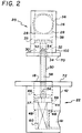
- Figures 2-4 show the first flow control member 20 in the first containerized system 12 engaging the proboscis member 50 of the second flow control member 22 .
- the proboscis member 50 remains inserted in the second seal 46 and is trapped in the second body member 42 by the second seal 46 .
- the second seal 46 is held flush mounted in the second body member 42 by an adhesive.
- the proboscis member 50 is sized for passing into and through channel 28 of the first flow control member 20 .
- a second biasing member i.e. second spring 60 , engages stop member 59 to force proboscis member 50 forward to seal against the second seal 46 , thus closing port 56 preventing fluid from escaping the second containerized system 14 or photoprinting machine when the first containerized system 12 is not present.
- first body member 26 of the first flow control member 20 may be provided with a first face flange 70 ; and, the second body member 42 of the second flow control member 22 may be provided with second face flange 72 .
- Face flanges 70,72 facilitate operation of the flow control system 10 , as described in details below.
- a rigid housing assemblage 100 may enclose the first containerized system 12 .
- a preferred housing assemblage 100 comprises first and second half portions 110,112 , each having a plurality of opposed slots 114 and snaps 116 for interlocking the first half portion 110 to the second half portion 112 .
- the snaps 116 of one fit snugly in the slots 114 of the other, thereby securely interlocking the half portions together.
- Interlocked half portions 110,112 are therefore formed having a closed end portion 122 and a partially opened end portion 124 for receiving and passing the necked down portion 102 of the first containerized system 12 , for example, a plastic bag, therethrough.
- flow control system 10 may comprise a cap 118 engaged with face flange 70 of the first containerized system 12 to retain the fluids therein before engagement with the second containerized system 14 .
- the housing assemblage 100 enclosing first containerized system 12 is mateable onto the photoprinting machine or second containerized system 14 in an inverted position.
- Cap 118 and first flow control member 20 normally are positioned at the bottom of the first containerized system 12 when inverted for fluid transfer between the two containerized systems 12,14 .
- second containerized system 14 contains the second flow control member 22 having proboscis member 50 projecting upwardly toward the first flow control member 20 positioned in the first containerized system 12 .
- the first opening 16 of the first containerized system 12 is urged toward the second opening 18 of the second containerized system 14 .
- the first face flange 70 of the first body member 26 can be urged toward the second face flange 72 of the second body member 46 to achieve the same result.
- the proboscis member 50 engages first seal 32 , partially withdraws through the second seal 46 toward the shoulder 48, and penetrates the first opening 34 of the first seal 32 .
- the open end portion 52 of the proboscis member 50 engages and displaces the piston member 38 into deforming contact with the annular spring 36 , thereby placing the entrance port 33 in fluid communication with notches 54, open end 52 and through channel 58 of the proboscis member 50 .
- the proboscis member 50 withdraws through the opening of the second seal 46 and comes to rest on shoulder 48.
- a fluid flow path is thereby opened from the entrance port 33 , through the open end 52 of the proboscis member 50 , through the through channel 58 of the proboscis member 50 , through the exit port 56 , through axial bore 57, and to the fluid inlet channel 61 of the second containerized system 14 .
- the first flow control member 20 of the first containerized system 12 is urged away from the second flow control member 22 of the second containerized system 14 , as described in detail above.
- the proboscis member 50 partially withdraws from the first opening 34 of the first seal 32 and away from the piston member 38 thereby allowing the piston member 38 to seal against the first seal 32 .
- the exit port 56 of the proboscis member 50 is positioned in a sealing relations with the second seal 46 , thus closing the open fluid flow path between the first and second containerized systems 12,14 .
- the proboscis member 50 when transferring a fluid from one containerized system to another (as shown in Figs. 2-4), the first opening 16 of the first containerized system 12 is urged toward the second opening 18 of the second containerized system 14 , the proboscis member 50 partially withdraws from the second seal 46 toward the shoulder portion 48 , and penetrates the first opening 34 of the first seal 32 .
- the open end portion 52 of the proboscis member 50 engages and displaces the piston member 38 into deforming contact with the spring member 36 thereby positioning the entrance port 33 in fluid communications with the through channel 58 of the proboscis member 50 .
- the proboscis member 50 withdraws through the second opening 45 of the second seal 46 and comes to rest on the shoulder portion 48 in the second body member 46 , thereby enabling an open fluid flow path from the entrance port 33 , through the open end 52 of the proboscis member 50 , through the through channel 58 of the proboscis member 50 , through the exit port 56 , through axial bore 57 and to the fluid inlet channel 61 of the second containerized system 14 .
- the first opening 16 of the first containerized system 12 is urged away from the second opening 18 of the second containerized system 14 .
- the proboscis member 50 partially withdraws from the first opening 34 of the first seal 32 and away from the piston member 38 thereby allowing the piston member 38 to seal against the first seal 32 .
- the exit port 56 of the proboscis member 50 is positioned in a sealing relation with the second seal 46 , thus closing the open fluid flow path between the first and second containerized systems 12,14 .
- a method for controlling fluid flow from a first containerized system 12 having a first opening 16 , to a second containerized system 14 having a second opening 18 comprises the step of providing first and second flow control members 20,22 positioned in the openings of the containerized systems, as described in details above (Fig. 1).
- the first opening 16 of the first containerized system 12 is urged toward the second opening 18 of the second containerized system 14 so that the proboscis member 50 of the second flow control member 22 at least partially penetrates the first opening 34 of the first flexible seal 32 , and subsequently engages and then displaces the piston member 38 toward the spring member 36 thereby opening a first flow path extending between the entrance port 33 , the opening 52 of the proboscis member 50 , and through the through channel 58 of the proboscis member 50 . Further, the first opening 16 of the first containerized system 12 is urged into proximate contact with the second opening 18 of the second containerized system 14 .
- a second fluid flow path is opened extending from the entrance port 33 , to the opening 52 and through channel 58 of the proboscis member 50 , through the exit port 56 of the proboscis member 50 , through axial bore 57 and terminating in the second fluid flow channel or inlet channel 61 of the second containerized system.
- the second opening 18 of the second containerized system 14 is urged away from the first opening 16 of the first containerized system 12 thereby closing the first fluid flow path and the second fluid flow path.
- the flow control system 20 may also include an O-ring 80 supported on the first seal 32 for sealing between first seal 32 and piston member 36 against leakage. This is shown schematically in Figure 3.
- the advantage of the O-ring 80 is that it provides additional positive sealing of the orifice 52 surrounding the through channel 58 of the proboscis member 50 against leakage.
- the method of the invention may alternatively include the step of providing a spring retaining slot 90 in the interior walls of the first body member 26 of the first containerized system to retain the spring member when deformed by the piston.
- the spring retaining slot 90 preferably extends along a circumferential portion of the wall of the first body member 26 .
- the operator places the first containerized system 12 onto the second flow control system 22 positioned in the second opening 18 of the machine or second containerized system 14 (See Figs. 1-4).
- the first and second flow control members 20,22 are positioned in fluid communications with one another so that a flow path between them can be alternatively opened and closed as described.
- the proboscis member 50 of the second containerized system 14 penetrates the first seal 32 of the first flow control member 20 , it is forced to retract in the second flow control member 22 by an amount approximately equal to the travel distance of the proboscis member 50 . This action opens the fluid path in the second flow control member 22 but does not open any fluid path to the atmosphere (see Figure 4).
- the proboscis member 50 is displaced farther into contact with the piston member 38 of the first flow control member 20 and continues to force the piston member away from the first seal 32 . This action opens the fluid path of the first flow control member 20 and fluid can now flow into or out of the second containerized system 14 or machine from the bottle or first containerized system 12 .
- the fluid passes from the bottle or first containerized system 12 into the first flow control member 20 through the first body member 26 . It then enters the opening 52 in the end of the proboscis member 50 and passes through the through channel 58 and out the side hole or exit port 56 in the proboscis member 50 . After exiting the proboscis member 50 , the fluid then passes through axial bore 57 and enters the inlet channel 61 of the second containerized system 14 thereby replenishing the second containerized system 14 with the fluid.
Abstract
Description
- The present invention relates to a flow control system and method. More particularly, the invention concerns a method and system for controlling the flow of fluid between mating containerized systems, such as a chemical replenishment container and a photoprinting machine, substantially without leaking and exposing the user to such fluid.
- Flow control devices, such as valves, are widely known to be used for regulating the flow of materials, primarily fluids, from one containerized system to another.
- A conventional way to supply a fluid material to a containerized system, such as photoprinting machine, involves dispensing the fluid material from a receptacle, for example a flexible container, into a fluid reservoir or distribution channel in the photoprinting machine. The flexible containers or bottles currently used to replenish chemicals in these machines require that the user first open the container and then pour the contents into the photoprinting machine. One problem that results during the transfer of the chemicals is leakage. Chemical leakage, of course, exposes the operator to potential hazardous effects. Moreover, materials waste and unnecessary expense are related problems that persist with existing flow control systems. These shortcomings necessitate a need for an improved flow control system and method which can supply materials, such as photographic chemicals, to photoprinting machines, and the like, in a containerized system without leakage. Such systems would then present to the operator as a dripless or dry transfer system.
- Consequently, it is necessary in the prior art to provide an apparently dry system for transferring materials between containerized systems. Preferably, in this system, a flow control or valving arrangement which communicates with both containerized systems (e.g., the flexible container for photographic chemicals and the photoprinting machine) is utilized such that when one containerized system is removed from the other, the valve would close and the user would not be exposed to leakage.
- In U.S. patent 4,958,666 to Kocourek et al., a storage canister for process fluids includes a receptacle having leakage proof pouches of elastic material each having an opening closed by a control valve. The normally closed controlled valve is activated by suction or by over-pressure from suction or pressure devices in the processing apparatus.
- It is, therefore, an object of the invention to provide a flow control system that eliminates leakage during fluid transfer between mating containerized systems.
- Another object of the invention is to provide a flow control system for controlling the supply of a fluid to a containerized system without the user having to first open the containerized system prior to transferring the fluid into another containerized system.
- Still another object of the present invention is to provide a flow control system for controlling the supply of a fluid from a first to a second containerized system such that when it is desired to remove the first containerized system from the second containerized system, no fluid is leaked during the process.
- Another object of the invention is to provide a flow control system that can open and close a flow path between mating containerized systems without leakage.
- Yet another object of the invention is to provide a method for transferring fluids between mating containerized system without leakage and waste of the transferred material.
- Accordingly, for accomplishing these and other objects of the invention, there is provided a flow control system for controlling the flow of fluid between first and second containerized systems. The first and second containerized systems include first and second openings, respectively. The flow control system comprises a first flow control member positioned at the first opening of the first containerized system. First flow control member has a first body member, a first fluid flow channel, a first seal having a first opening therethrough arranged in the first fluid flow channel, a fluid entrance port in fluid communications with the first fluid flow channel, a spring member retained in the first fluid flow channel, and a piston member normally biased by the spring against the first seal to close the first fluid channel.
- Further, the flow control system includes a second flow control member positioned at the second opening. Second flow control member comprises a second body member having a second fluid flow channel, a second seal having a second opening therethrough arranged in the second fluid flow channel, a stop member, and a proboscis member slidable axially in the second opening of the second seal and in the first opening of the first seal, the proboscis member having an open end portion, and at least one exit port on the opposite end within the second body member, and a through channel extending from the open end to the exit port.
- In this embodiment of the invention, when the first opening of the first containerized system is urged toward the second opening of the second containerized system, the proboscis member partially withdraws from the second seal toward the stop member, and penetrates the first opening of the first seal. The open end portion of the proboscis member engages and displaces the piston member into deforming contact with the spring member thereby positioning the entrance port in fluid communication with the through channel of the proboscis member.
- Moreover, when the first opening of the first containerized system is urged into proximate contact with the second opening of the second containerized system, the proboscis member withdraws through the second opening of the second seal and comes to rest on the stop member in the second housing, thereby enabling an open fluid flow path from the entrance port, through the open end of the proboscis member, through the through channel of the proboscis member, through the exit port, and to the fluid inlet channel of the second containerized system.
- Finally, when the first opening of the first containerized system is urged away from the second opening of the second containerized system, the proboscis member partially withdraws from the first opening of the first seal and away from the piston member thereby allowing the piston member to seal against the first seal, and sequentially the exit port of the proboscis member is positioned in sealing relation with the second seal, thus closing the open fluid flow path between the first and second containerized system.
- The method of the invention is useful for controlling fluid flow from a first containerized system having an openable end portion, to a second containerized system having a fluid inlet channel. The method comprises the step of providing a first flow control member, as previously described, positioned in the openable end portion of the container and providing a second flow control member, as described above, positioned in the fluid inlet channel of the second containerized system. A second face flange of the second flow control member is urged onto a first face flange of the first flow control member so that the proboscis member at least partially engages the first flexible seal and displaces the piston toward the spring member thereby opening a first flow path extending between the entrance port, the opening of the proboscis member, and through the through channel of the proboscis member. The second face flange of the second flow control member is urged into proximate contact with the first face flange of the first flow control member thereby opening a second fluid flow path extending from the entrance port, to the opening and through channel of the proboscis member, through the exit port of the proboscis member and terminating in the inlet channel of the second containerized system. When it is desired to terminate the flow between the first and second containerized systems, the second face flange of the second flow control member is urged away from the first face flange of the first flow control member, thereby closing the first and second flow paths between the entrance port and the proboscis member and the exit port and the inlet channel, respectively.
- Accordingly, advantageous effects of the present invention are that it provides flow control systems and a method for controlling the flow of fluids between mating containerized systems without leakage, that are simple to operate, easy to manufacture, and inexpensive to produce.
- The foregoing as well as other objects, features and advantages of this invention will become more apparent from the appended Figures, wherein like reference numerals denote like elements, and wherein:
- Figure 1 is an exploded perspective view of the flow control system according to the invention;
- Figure 2 is a sectional view of the first and second flow control members with the proboscis member of the second flow control member just entering the first control member;
- Figure 3 is a sectional view of both flow control members with the proboscis member of the second flow control member open;
- Figure 4 is a sectional view of both flow control members with the proboscis member fully communicating with the first flow control member, thereby opening a fluid flow path between both control members;
- Figure 5 is an exploded perspective view of the first flow control member;
- Figure 6 is an exploded perspective view of the second flow control member;
- Figure 7 is a side view of fluid supply container and communicating flow control members therein;
- Figure 8 is an isometric view of a half portion of a housing assemblage for enclosing a containerized system; and
- Figure 9 is an isometric view of an assembled housing for one containerized system.
- Turning now to the drawings, and more particularly to Figure 1, a
flow control system 10 is illustrated for controlling the flow of fluids between mating first and second containerizedsystems system 12 has afirst opening 16, and the second containerizedsystem 14 includes asecond opening 18, each for containing members of theflow control system 10. In a particular embodiment of the invention, the first containerizedsystem 12 may be any sort of fluid container, such as a cartridge, bag-in-a-box or bottle; and, the second containerized system may be a fluid replenishable machine such as a photoprinting machine or copier. Therefore, broadly defined,flow control system 10 comprises a firstflow control member 20 positioned at thefirst opening 16 of the first containerizedsystem 12; and, a secondflow control member 22 positioned at thesecond opening 18 of the second containerizedsystem 14. - In Figs. 1-5, first
flow control member 20 is shown to include afirst body member 26, a firstfluid flow channel 28 passing through acentral portion 30 of thebody member 26, afluid entrance port 33 in fluid communication with theflow channel 28, and afirst seal 32 having a first opening 34 therethrough arranged in the firstfluid flow channel 28. Moreover, as best seen in Fig. 5, a first biasing means, preferably anannular spring 36, is retained in the firstfluid flow channel 28, normally biasing apiston member 38 against thefirst seal 32 to close the firstfluid flow channel 28 when desired. Moreover, in Figs 2-4,annular spring 36 is shown providing support forpiston member 38 againstfirst seal 32, thereby preventing fluid from escaping the first containerizedsystem 12. - Referring again to Figs. 1-4, and 6, second
flow control member 22, which cooperates with thefirst control member 20, is positioned in thesecond opening 18 of the second containerizedsystem 14. The secondflow control member 22 comprises asecond body member 42 having a secondfluid flow channel 44, a secondflexible seal 46 arranged in the secondfluid flow channel 44, ashoulder portion 48 positioned withinchannel 44 beyond the secondflexible seal 46, and adisplaceable proboscis member 50. As best illustrated in Fig. 6, theproboscis member 50 has anopen end 52 and a notchedportion 54 surrounding theopen end 52 which projects outwardly of thesecond body member 42. Further,proboscis member 50 includes at least oneradial exit port 56, a throughchannel 58 extending from theopen end 52 to theexit port 56, and an integral or attachedstop member 59 positioned beyond theexit port 56 for contacting theshoulder portion 48 of thesecond housing 42. Anaxial bore 57 is provided throughstop member 59. - Figures 2-4 show the first
flow control member 20 in the first containerizedsystem 12 engaging theproboscis member 50 of the secondflow control member 22. According to Fig. 4, when the twoflow control members proboscis member 50 remains inserted in thesecond seal 46 and is trapped in thesecond body member 42 by thesecond seal 46. Thesecond seal 46 is held flush mounted in thesecond body member 42 by an adhesive. As indicated below, theproboscis member 50 is sized for passing into and throughchannel 28 of the firstflow control member 20. - Again turning to Figs. 2-4, a second biasing member, i.e.
second spring 60, engages stopmember 59 to forceproboscis member 50 forward to seal against thesecond seal 46, thus closingport 56 preventing fluid from escaping thesecond containerized system 14 or photoprinting machine when thefirst containerized system 12 is not present. - Although not required in the preferred embodiment of the invention, as depicted in Figs. 1-4,
first body member 26 of the firstflow control member 20 may be provided with afirst face flange 70; and, thesecond body member 42 of the secondflow control member 22 may be provided withsecond face flange 72.Face flanges flow control system 10, as described in details below. - In Figs. 7-11, alternatively, a
rigid housing assemblage 100 may enclose thefirst containerized system 12. According to Figs. 7-9, apreferred housing assemblage 100 comprises first and second half portions 110,112, each having a plurality ofopposed slots 114 and snaps 116 for interlocking thefirst half portion 110 to thesecond half portion 112. Thus, when the two half portions 110,112 are assembled, thesnaps 116 of one fit snugly in theslots 114 of the other, thereby securely interlocking the half portions together. Interlocked half portions 110,112 are therefore formed having aclosed end portion 122 and a partially openedend portion 124 for receiving and passing the necked downportion 102 of thefirst containerized system 12, for example, a plastic bag, therethrough. According to Fig. 7,flow control system 10, as described above, may comprise acap 118 engaged withface flange 70 of thefirst containerized system 12 to retain the fluids therein before engagement with thesecond containerized system 14. - According to Fig. 7, the
housing assemblage 100 enclosingfirst containerized system 12 is mateable onto the photoprinting machine orsecond containerized system 14 in an inverted position.Cap 118 and firstflow control member 20 normally are positioned at the bottom of thefirst containerized system 12 when inverted for fluid transfer between the two containerizedsystems second containerized system 14 contains the secondflow control member 22 havingproboscis member 50 projecting upwardly toward the firstflow control member 20 positioned in thefirst containerized system 12. - Accordingly, in a preferred embodiment of invention, when transferring a fluid from one containerized system to the other, the
first opening 16 of thefirst containerized system 12, for example plastic bag containing photographic chemicals, is urged toward thesecond opening 18 of thesecond containerized system 14. Alternatively, thefirst face flange 70 of thefirst body member 26 can be urged toward thesecond face flange 72 of thesecond body member 46 to achieve the same result. In either instance, theproboscis member 50 engagesfirst seal 32, partially withdraws through thesecond seal 46 toward theshoulder 48, and penetrates thefirst opening 34 of thefirst seal 32. Theopen end portion 52 of theproboscis member 50 engages and displaces thepiston member 38 into deforming contact with theannular spring 36, thereby placing theentrance port 33 in fluid communication withnotches 54,open end 52 and throughchannel 58 of theproboscis member 50. - Further, when the
first opening 16 of thefirst containerized system 12 is urged into proximate contact with thesecond opening 18 of thesecond containerized system 14 or photoprinting machine, theproboscis member 50 withdraws through the opening of thesecond seal 46 and comes to rest onshoulder 48. A fluid flow path is thereby opened from theentrance port 33, through theopen end 52 of theproboscis member 50, through the throughchannel 58 of theproboscis member 50, through theexit port 56, throughaxial bore 57, and to thefluid inlet channel 61 of thesecond containerized system 14. - Furthermore, as illustrated in Figs. 2-4, to terminate the flow of fluid between the first and second
containerized systems flow control member 20 of thefirst containerized system 12 is urged away from the secondflow control member 22 of thesecond containerized system 14, as described in detail above. As indicated, theproboscis member 50 partially withdraws from thefirst opening 34 of thefirst seal 32 and away from thepiston member 38 thereby allowing thepiston member 38 to seal against thefirst seal 32. Sequentially, theexit port 56 of theproboscis member 50 is positioned in a sealing relations with thesecond seal 46, thus closing the open fluid flow path between the first and secondcontainerized systems - In an alternative embodiment of the invention, when transferring a fluid from one containerized system to another (as shown in Figs. 2-4), the
first opening 16 of thefirst containerized system 12 is urged toward thesecond opening 18 of thesecond containerized system 14, theproboscis member 50 partially withdraws from thesecond seal 46 toward theshoulder portion 48, and penetrates thefirst opening 34 of thefirst seal 32. Theopen end portion 52 of theproboscis member 50 engages and displaces thepiston member 38 into deforming contact with thespring member 36 thereby positioning theentrance port 33 in fluid communications with the throughchannel 58 of theproboscis member 50. Theproboscis member 50 withdraws through thesecond opening 45 of thesecond seal 46 and comes to rest on theshoulder portion 48 in thesecond body member 46, thereby enabling an open fluid flow path from theentrance port 33, through theopen end 52 of theproboscis member 50, through the throughchannel 58 of theproboscis member 50, through theexit port 56, throughaxial bore 57 and to thefluid inlet channel 61 of thesecond containerized system 14. - As above, it is desired to terminate flow between the containerized
systems first opening 16 of thefirst containerized system 12 is urged away from thesecond opening 18 of thesecond containerized system 14. Theproboscis member 50 partially withdraws from thefirst opening 34 of thefirst seal 32 and away from thepiston member 38 thereby allowing thepiston member 38 to seal against thefirst seal 32. Theexit port 56 of theproboscis member 50 is positioned in a sealing relation with thesecond seal 46, thus closing the open fluid flow path between the first and secondcontainerized systems - In yet another embodiment of the invention, a method for controlling fluid flow from a
first containerized system 12 having afirst opening 16, to asecond containerized system 14 having asecond opening 18, comprises the step of providing first and secondflow control members first opening 16 of thefirst containerized system 12 is urged toward thesecond opening 18 of thesecond containerized system 14 so that theproboscis member 50 of the secondflow control member 22 at least partially penetrates thefirst opening 34 of the firstflexible seal 32, and subsequently engages and then displaces thepiston member 38 toward thespring member 36 thereby opening a first flow path extending between theentrance port 33, theopening 52 of theproboscis member 50, and through the throughchannel 58 of theproboscis member 50. Further, thefirst opening 16 of thefirst containerized system 12 is urged into proximate contact with thesecond opening 18 of thesecond containerized system 14. When the two containerizedsystems entrance port 33, to theopening 52 and throughchannel 58 of theproboscis member 50, through theexit port 56 of theproboscis member 50, throughaxial bore 57 and terminating in the second fluid flow channel orinlet channel 61 of the second containerized system. When it is desired to terminate fluid flow between the two containerizedsystems second opening 18 of thesecond containerized system 14 is urged away from thefirst opening 16 of thefirst containerized system 12 thereby closing the first fluid flow path and the second fluid flow path. - The
flow control system 20 may also include an O-ring 80 supported on thefirst seal 32 for sealing betweenfirst seal 32 andpiston member 36 against leakage. This is shown schematically in Figure 3. The advantage of the O-ring 80 is that it provides additional positive sealing of theorifice 52 surrounding the throughchannel 58 of theproboscis member 50 against leakage. - Moreover, according to Figs. 1 and 5, the method of the invention may alternatively include the step of providing a
spring retaining slot 90 in the interior walls of thefirst body member 26 of the first containerized system to retain the spring member when deformed by the piston. Thespring retaining slot 90 preferably extends along a circumferential portion of the wall of thefirst body member 26. - To use the
flow control systems 10 of present invention, the operator places thefirst containerized system 12 onto the secondflow control system 22 positioned in thesecond opening 18 of the machine or second containerized system 14 (See Figs. 1-4). As described above, the first and secondflow control members proboscis member 50 of thesecond containerized system 14 penetrates thefirst seal 32 of the firstflow control member 20, it is forced to retract in the secondflow control member 22 by an amount approximately equal to the travel distance of theproboscis member 50. This action opens the fluid path in the secondflow control member 22 but does not open any fluid path to the atmosphere (see Figure 4). Next theproboscis member 50 is displaced farther into contact with thepiston member 38 of the firstflow control member 20 and continues to force the piston member away from thefirst seal 32. This action opens the fluid path of the firstflow control member 20 and fluid can now flow into or out of thesecond containerized system 14 or machine from the bottle orfirst containerized system 12. - As indicated, the fluid passes from the bottle or
first containerized system 12 into the firstflow control member 20 through thefirst body member 26. It then enters theopening 52 in the end of theproboscis member 50 and passes through the throughchannel 58 and out the side hole or exitport 56 in theproboscis member 50. After exiting theproboscis member 50, the fluid then passes throughaxial bore 57 and enters theinlet channel 61 of thesecond containerized system 14 thereby replenishing thesecond containerized system 14 with the fluid. - Removal of the
first containerized system 12 from the machine orsecond containerized system 14 reverses the above action of theflow control members 

Claims (6)
- A flow control system (10)for controlling the flow of fluid between first and second containerized systems (12, 14), the first containerized system having a first opening (16), and the second containerized system having a second opening (18), comprising:
a first flow control member (20) positioned at the first opening of the first containerized system, the first flow control member comprising a first body member (26), a first fluid flow channel (28), a first seal (32) having a first opening (34) therethrough arranged in said first fluid flow channel, a fluid entrance port (33) in fluid communication with the first fluid flow channel, a spring member (36) retained in said first fluid flow channel, and a piston member (38) normally biased by the spring against the first seal to close the first fluid channel;
a second flow control member (22) positioned at the second opening, the second flow control member comprising a second body member (42) having a second fluid flow channel (44), a second seal (46) having a second opening therethrough arranged in the second fluid flow channel, a shoulder portion (48) in the second fluid flow channel, and a proboscis member (50) slidable axially in the second opening of the second seal and in the first opening of the first seal, the proboscis member having an open end portion (52, 54), and at least one exit port (56) on the opposite end within the second body member, and a through channel (58) extending from the open end to the exit port, the proboscis member being attached to a stop member (59);
wherein, when the first opening of the first containerized system is urged toward the second opening of the second containerized system, the proboscis member partially withdraws from the second seal and the stop member moves toward the shoulder portion; the proboscis member penetrates the first opening of the first seal, the open end portion of the proboscis member engages and displaces the piston member into deforming contact with the spring member thereby positioning the entrance port in fluid communication with the through channel of the proboscis member; and
wherein, when the first opening of the first containerized system is urged into proximate contact with the second opening of the second containerized system, the proboscis member withdraws through the second opening of the second seal and the stop member comes to rest on the shoulder portion in the second housing, thereby enabling an open fluid flow path from the entrance port, through the open end of the proboscis member, through the through channel of the proboscis member, through the exit port, and to a fluid inlet channel (61) of the second containerized system; and
wherein, when the first opening of the first containerized system is urged away from the second opening of the second containerized system, the proboscis member partially withdraws from the first opening of the first seal and away from the piston member thereby allowing the piston member to seal against the first seal, and sequentially the exit port of the proboscis member is positioned in a sealing relation with the second seal, thus closing the open fluid flow path between the first and second containerized systems. - The flow control system recited in claim 1 wherein said second flow control member confines said exit port of said proboscis member within said second seal when said second fluid flow path is closed.
- The flow control system recited in claim 1 wherein the first and second seals are made of flexible materials.
- The flow control system recited in claim 1 wherein an opening is provided in the first fluid flow channel for retaining deformed portions of the spring when engaged by the piston.
- The flow control system recited in claim 1 wherein the first containerized system includes a plastic bag positioned in a housing assemblage (100) comprising first and second half portions (110, 112), each having a plurality of opposed slots and snaps (114, 116) for interlocking said first half portion to said second half portion thereby forming interlocked half portions, said interlocked half portions defining a closed end portion and a partially opened end portion for receiving a necked down portion of the first body member.
- A method for controlling fluid flow from a first containerized system (12) having a first opening (16), to a second containerized system (14) having a second opening (18), said method comprising the steps of:
providing a first flow control member (20) positioned in the first opening of the containerized system, said first flow control member comprising a first body member (26), a first fluid flow channel (28), a first seal (32) having a first opening (34) therethrough arranged in said first fluid flow channel, a fluid entrance port (33) in fluid communication with the first fluid flow channel, a spring member (36) retained in said first fluid flow channel, and a piston member (38) normally biased by the spring against the first seal to close the first fluid channel;
providing a second flow control member (22) positioned in the fluid inlet channel of the second containerized system, said second flow control member comprising a second body member (42) having a second fluid flow channel (44), a second seal (46) having a second opening therethrough arranged in the second fluid flow channel, a shoulder portion (48) in the second fluid flow channel, and a proboscis member (50) slidable axially in the second opening of the second seal until, in one direction, it engages the shoulder portion and enters the first opening of the first seal, the proboscis member having an open end portion, and at least one exit port (56) on the opposite end within the second body member, and a through channel (58) extending from the open end to the exit port;
urging the first opening of the first containerized system toward the second opening of the second containerized system so that the proboscis member at least partially penetrates the first opening of the first seal, and subsequently engages and then displaces the piston toward the spring member thereby opening a first flow path extending between the entrance port, the opening of the proboscis member, and through the through channel of the proboscis member; and
urging the first opening of the first containerized system into proximate contact with the second opening of the second containerized system thereby opening a second fluid flow path extending from the entrance port, to the opening and through channel of the proboscis member, through the exit port of the proboscis member and terminating in the second fluid flow channel of the second containerized system.
Applications Claiming Priority (2)
| Application Number | Priority Date | Filing Date | Title |
|---|---|---|---|
| US220986 | 1994-03-31 | ||
| US08/220,986 US5560405A (en) | 1994-03-31 | 1994-03-31 | Flow control system and method |
Publications (3)
| Publication Number | Publication Date |
|---|---|
| EP0675405A2 true EP0675405A2 (en) | 1995-10-04 |
| EP0675405A3 EP0675405A3 (en) | 1996-04-03 |
| EP0675405B1 EP0675405B1 (en) | 2001-11-14 |
Family
ID=22825861
Family Applications (1)
| Application Number | Title | Priority Date | Filing Date |
|---|---|---|---|
| EP95420075A Expired - Lifetime EP0675405B1 (en) | 1994-03-31 | 1995-03-24 | Flow control system and method |
Country Status (8)
| Country | Link |
|---|---|
| US (1) | US5560405A (en) |
| EP (1) | EP0675405B1 (en) |
| JP (1) | JPH082592A (en) |
| KR (1) | KR950033748A (en) |
| BR (1) | BR9501284A (en) |
| CA (1) | CA2142760A1 (en) |
| DE (1) | DE69523802T2 (en) |
| TW (1) | TW258795B (en) |
Cited By (2)
| Publication number | Priority date | Publication date | Assignee | Title |
|---|---|---|---|---|
| EP1014190A1 (en) * | 1998-12-22 | 2000-06-28 | GID GmbH | Container for developing devices |
| US10478812B2 (en) | 2011-04-18 | 2019-11-19 | Dow Technology Investments Llc | Methods to store transition metal organophosphorous ligand based catalysts |
Families Citing this family (6)
| Publication number | Priority date | Publication date | Assignee | Title |
|---|---|---|---|---|
| US5967366A (en) * | 1998-05-28 | 1999-10-19 | Cason; Albert Franklin | Coin-operated fluid vending machine |
| EP1206386A4 (en) * | 1999-07-23 | 2002-10-30 | Scholle Corp | Connector assembly for fluid flow with rotary motion for connection and disconnection |
| US6644367B1 (en) | 1999-07-23 | 2003-11-11 | Scholle Corporation | Connector assembly for fluid flow with rotary motion for connection and disconnection |
| GB0018011D0 (en) * | 2000-07-21 | 2000-09-13 | Air Prod & Chem | A valve assembly apparatus and method of filling a pressurised gas container |
| US6467515B1 (en) * | 2001-11-29 | 2002-10-22 | Hwai-Tay Lin | Gas container |
| US6854494B2 (en) | 2002-10-31 | 2005-02-15 | Eastman Kodak Company | Cup and probe assembly for use in a valve system for transferring a liquid between two sources |
Citations (4)
| Publication number | Priority date | Publication date | Assignee | Title |
|---|---|---|---|---|
| US3698454A (en) * | 1971-07-08 | 1972-10-17 | Itek Corp | Container replacement system |
| EP0130853A1 (en) * | 1983-04-26 | 1985-01-09 | SAUNIER DUVAL EAU CHAUDE CHAUFFAGE S.D.E.C.C. - Société anonyme | Actuating device for filling a closed container |
| DE3742821C1 (en) * | 1987-12-17 | 1989-05-24 | Agfa Gevaert Ag | Storage canister for treatment liquids for photographic material that can be used in a wet treatment device |
| GB2263155A (en) * | 1992-01-08 | 1993-07-14 | Seaboard Lloyd Ltd | Check valve assembly |
Family Cites Families (14)
| Publication number | Priority date | Publication date | Assignee | Title |
|---|---|---|---|---|
| US497896A (en) * | 1893-05-23 | The morris petxss co | ||
| US2401674A (en) * | 1941-05-29 | 1946-06-04 | Lloyd W Vizay | Fluid transfer device |
| US3343718A (en) * | 1965-04-06 | 1967-09-26 | Capitol Packaging Co | Method of forming and dispensing aerosol dispensible polymerizable compositions |
| DE2219110C3 (en) * | 1972-04-19 | 1975-10-16 | Agfa-Gevaert Ag, 5090 Leverkusen | Apparatus for the wet treatment of photographic substrates |
| US4445551A (en) * | 1981-11-09 | 1984-05-01 | Bond Curtis J | Quick-disconnect coupling and valve assembly |
| US4750647A (en) * | 1985-04-12 | 1988-06-14 | Cohen Milton J | Non-aerosol dispenser |
| US4763683A (en) * | 1987-09-21 | 1988-08-16 | Catlow, Inc. | Breakaway coupling for a coaxial fuel supply hose |
| US5150811A (en) * | 1988-03-02 | 1992-09-29 | Kelston Henry J | Squeeze resistant carton holder |
| US4991635A (en) * | 1988-09-30 | 1991-02-12 | Liqui-Box Corporation | Decap dispensing system for water cooler bottles |
| US4874023A (en) * | 1988-09-30 | 1989-10-17 | Liqui-Box Corporation | Decap dispensing system for water cooler bottles |
| US5031676A (en) * | 1988-09-30 | 1991-07-16 | Liqui-Box Corporation | Decap dispensing system for water cooler bottles |
| US5070351A (en) * | 1989-10-13 | 1991-12-03 | E. I. Du Pont De Nemours And Company | Method and apparatus for processing photosensitive material |
| CA2011406C (en) * | 1990-03-02 | 1996-09-17 | Julien Bilodeau | Apparatus for discharging a fluid, and, more particularly, for spraying a liquid |
| JP2566475Y2 (en) * | 1991-02-20 | 1998-03-25 | コニカ株式会社 | Processing unit for integrated silver halide photosensitive material |
-
1994
- 1994-03-31 US US08/220,986 patent/US5560405A/en not_active Expired - Fee Related
-
1995
- 1995-02-16 TW TW084101428A patent/TW258795B/zh active
- 1995-02-17 CA CA002142760A patent/CA2142760A1/en not_active Abandoned
- 1995-03-15 JP JP7055986A patent/JPH082592A/en not_active Ceased
- 1995-03-24 EP EP95420075A patent/EP0675405B1/en not_active Expired - Lifetime
- 1995-03-24 DE DE69523802T patent/DE69523802T2/en not_active Expired - Fee Related
- 1995-03-30 BR BR9501284A patent/BR9501284A/en not_active Application Discontinuation
- 1995-03-31 KR KR1019950007264A patent/KR950033748A/en not_active Application Discontinuation
Patent Citations (4)
| Publication number | Priority date | Publication date | Assignee | Title |
|---|---|---|---|---|
| US3698454A (en) * | 1971-07-08 | 1972-10-17 | Itek Corp | Container replacement system |
| EP0130853A1 (en) * | 1983-04-26 | 1985-01-09 | SAUNIER DUVAL EAU CHAUDE CHAUFFAGE S.D.E.C.C. - Société anonyme | Actuating device for filling a closed container |
| DE3742821C1 (en) * | 1987-12-17 | 1989-05-24 | Agfa Gevaert Ag | Storage canister for treatment liquids for photographic material that can be used in a wet treatment device |
| GB2263155A (en) * | 1992-01-08 | 1993-07-14 | Seaboard Lloyd Ltd | Check valve assembly |
Cited By (2)
| Publication number | Priority date | Publication date | Assignee | Title |
|---|---|---|---|---|
| EP1014190A1 (en) * | 1998-12-22 | 2000-06-28 | GID GmbH | Container for developing devices |
| US10478812B2 (en) | 2011-04-18 | 2019-11-19 | Dow Technology Investments Llc | Methods to store transition metal organophosphorous ligand based catalysts |
Also Published As
| Publication number | Publication date |
|---|---|
| JPH082592A (en) | 1996-01-09 |
| US5560405A (en) | 1996-10-01 |
| DE69523802T2 (en) | 2002-08-14 |
| EP0675405A3 (en) | 1996-04-03 |
| TW258795B (en) | 1995-10-01 |
| EP0675405B1 (en) | 2001-11-14 |
| CA2142760A1 (en) | 1995-10-01 |
| BR9501284A (en) | 1995-10-31 |
| KR950033748A (en) | 1995-12-26 |
| DE69523802D1 (en) | 2001-12-20 |
Similar Documents
| Publication | Publication Date | Title |
|---|---|---|
| EP0992451B1 (en) | Connector with valve for fluid transfer | |
| EP0675072B1 (en) | Valve assemblage and method of use | |
| US5878798A (en) | Valve system | |
| CA1305954C (en) | Liquid feed system using a non-reusable container | |
| AU707860B2 (en) | Collapsible soap dispenser | |
| EP0941437B1 (en) | Non-leaking, non-venting liquid filled canister quick disconnect system | |
| US4948014A (en) | Two piece valved fluid dispenser | |
| EP0675405B1 (en) | Flow control system and method | |
| US8881958B2 (en) | Fluid dose-measuring device | |
| US4929109A (en) | Ink cartridge | |
| RU2749060C1 (en) | Liquid storage | |
| KR100190410B1 (en) | Dilution station | |
| JP2653662B2 (en) | Liquid storage and transfer equipment | |
| WO1983001605A1 (en) | Coupling and valve assembly for a liquid dispenser | |
| CA2244206C (en) | Paint pouch fitting | |
| EP1181235A1 (en) | Liquid transfer system with flow control | |
| US20200398578A1 (en) | Print substance donor containers | |
| EP0709605B1 (en) | Automatic valve | |
| CN212829829U (en) | Connector and fluid container | |
| JPS62271873A (en) | Teeming device | |
| WO2017201366A1 (en) | Measuring adapter assembly for closed loop fluid transfer system | |
| MXPA95001569A (en) | Set of valves and method of | |
| JPH051756Y2 (en) |
Legal Events
| Date | Code | Title | Description |
|---|---|---|---|
| PUAI | Public reference made under article 153(3) epc to a published international application that has entered the european phase |
Free format text: ORIGINAL CODE: 0009012 |
|
| AK | Designated contracting states |
Kind code of ref document: A2 Designated state(s): CH DE FR GB IT LI |
|
| PUAL | Search report despatched |
Free format text: ORIGINAL CODE: 0009013 |
|
| AK | Designated contracting states |
Kind code of ref document: A3 Designated state(s): BE CH DE FR GB IT LI |
|
| 17P | Request for examination filed |
Effective date: 19960919 |
|
| 17Q | First examination report despatched |
Effective date: 20000120 |
|
| GRAG | Despatch of communication of intention to grant |
Free format text: ORIGINAL CODE: EPIDOS AGRA |
|
| GRAG | Despatch of communication of intention to grant |
Free format text: ORIGINAL CODE: EPIDOS AGRA |
|
| GRAH | Despatch of communication of intention to grant a patent |
Free format text: ORIGINAL CODE: EPIDOS IGRA |
|
| RBV | Designated contracting states (corrected) |
Designated state(s): CH DE FR GB IT LI |
|
| GRAH | Despatch of communication of intention to grant a patent |
Free format text: ORIGINAL CODE: EPIDOS IGRA |
|
| GRAA | (expected) grant |
Free format text: ORIGINAL CODE: 0009210 |
|
| AK | Designated contracting states |
Kind code of ref document: B1 Designated state(s): CH DE FR GB IT LI |
|
| REG | Reference to a national code |
Ref country code: CH Ref legal event code: EP |
|
| REF | Corresponds to: |
Ref document number: 69523802 Country of ref document: DE Date of ref document: 20011220 |
|
| REG | Reference to a national code |
Ref country code: GB Ref legal event code: IF02 |
|
| PGFP | Annual fee paid to national office [announced via postgrant information from national office to epo] |
Ref country code: GB Payment date: 20020205 Year of fee payment: 8 |
|
| REG | Reference to a national code |
Ref country code: CH Ref legal event code: NV Representative=s name: KIRKER & CIE SA |
|
| PGFP | Annual fee paid to national office [announced via postgrant information from national office to epo] |
Ref country code: FR Payment date: 20020228 Year of fee payment: 8 |
|
| PGFP | Annual fee paid to national office [announced via postgrant information from national office to epo] |
Ref country code: CH Payment date: 20020325 Year of fee payment: 8 |
|
| PGFP | Annual fee paid to national office [announced via postgrant information from national office to epo] |
Ref country code: DE Payment date: 20020327 Year of fee payment: 8 |
|
| ET | Fr: translation filed | ||
| PLBE | No opposition filed within time limit |
Free format text: ORIGINAL CODE: 0009261 |
|
| STAA | Information on the status of an ep patent application or granted ep patent |
Free format text: STATUS: NO OPPOSITION FILED WITHIN TIME LIMIT |
|
| 26N | No opposition filed | ||
| PG25 | Lapsed in a contracting state [announced via postgrant information from national office to epo] |
Ref country code: GB Free format text: LAPSE BECAUSE OF NON-PAYMENT OF DUE FEES Effective date: 20030324 |
|
| PG25 | Lapsed in a contracting state [announced via postgrant information from national office to epo] |
Ref country code: LI Free format text: LAPSE BECAUSE OF NON-PAYMENT OF DUE FEES Effective date: 20030331 Ref country code: CH Free format text: LAPSE BECAUSE OF NON-PAYMENT OF DUE FEES Effective date: 20030331 |
|
| PG25 | Lapsed in a contracting state [announced via postgrant information from national office to epo] |
Ref country code: DE Free format text: LAPSE BECAUSE OF NON-PAYMENT OF DUE FEES Effective date: 20031001 |
|
| GBPC | Gb: european patent ceased through non-payment of renewal fee |
Effective date: 20030324 |
|
| REG | Reference to a national code |
Ref country code: CH Ref legal event code: PL |
|
| PG25 | Lapsed in a contracting state [announced via postgrant information from national office to epo] |
Ref country code: FR Free format text: LAPSE BECAUSE OF NON-PAYMENT OF DUE FEES Effective date: 20031127 |
|
| REG | Reference to a national code |
Ref country code: FR Ref legal event code: ST |
|
| PG25 | Lapsed in a contracting state [announced via postgrant information from national office to epo] |
Ref country code: IT Free format text: LAPSE BECAUSE OF NON-PAYMENT OF DUE FEES Effective date: 20050324 |