EP0675462A2 - System and method of generating compressed video graphics images - Google Patents
System and method of generating compressed video graphics images Download PDFInfo
- Publication number
- EP0675462A2 EP0675462A2 EP95301882A EP95301882A EP0675462A2 EP 0675462 A2 EP0675462 A2 EP 0675462A2 EP 95301882 A EP95301882 A EP 95301882A EP 95301882 A EP95301882 A EP 95301882A EP 0675462 A2 EP0675462 A2 EP 0675462A2
- Authority
- EP
- European Patent Office
- Prior art keywords
- block
- motion vectors
- model
- image frame
- image
- Prior art date
- Legal status (The legal status is an assumption and is not a legal conclusion. Google has not performed a legal analysis and makes no representation as to the accuracy of the status listed.)
- Granted
Links
Images


Classifications
-
- G—PHYSICS
- G06—COMPUTING; CALCULATING OR COUNTING
- G06T—IMAGE DATA PROCESSING OR GENERATION, IN GENERAL
- G06T7/00—Image analysis
-
- H—ELECTRICITY
- H04—ELECTRIC COMMUNICATION TECHNIQUE
- H04N—PICTORIAL COMMUNICATION, e.g. TELEVISION
- H04N19/00—Methods or arrangements for coding, decoding, compressing or decompressing digital video signals
- H04N19/10—Methods or arrangements for coding, decoding, compressing or decompressing digital video signals using adaptive coding
- H04N19/169—Methods or arrangements for coding, decoding, compressing or decompressing digital video signals using adaptive coding characterised by the coding unit, i.e. the structural portion or semantic portion of the video signal being the object or the subject of the adaptive coding
- H04N19/17—Methods or arrangements for coding, decoding, compressing or decompressing digital video signals using adaptive coding characterised by the coding unit, i.e. the structural portion or semantic portion of the video signal being the object or the subject of the adaptive coding the unit being an image region, e.g. an object
-
- H—ELECTRICITY
- H04—ELECTRIC COMMUNICATION TECHNIQUE
- H04N—PICTORIAL COMMUNICATION, e.g. TELEVISION
- H04N19/00—Methods or arrangements for coding, decoding, compressing or decompressing digital video signals
- H04N19/10—Methods or arrangements for coding, decoding, compressing or decompressing digital video signals using adaptive coding
- H04N19/102—Methods or arrangements for coding, decoding, compressing or decompressing digital video signals using adaptive coding characterised by the element, parameter or selection affected or controlled by the adaptive coding
- H04N19/103—Selection of coding mode or of prediction mode
- H04N19/107—Selection of coding mode or of prediction mode between spatial and temporal predictive coding, e.g. picture refresh
-
- H—ELECTRICITY
- H04—ELECTRIC COMMUNICATION TECHNIQUE
- H04N—PICTORIAL COMMUNICATION, e.g. TELEVISION
- H04N19/00—Methods or arrangements for coding, decoding, compressing or decompressing digital video signals
- H04N19/10—Methods or arrangements for coding, decoding, compressing or decompressing digital video signals using adaptive coding
- H04N19/102—Methods or arrangements for coding, decoding, compressing or decompressing digital video signals using adaptive coding characterised by the element, parameter or selection affected or controlled by the adaptive coding
- H04N19/124—Quantisation
-
- H—ELECTRICITY
- H04—ELECTRIC COMMUNICATION TECHNIQUE
- H04N—PICTORIAL COMMUNICATION, e.g. TELEVISION
- H04N19/00—Methods or arrangements for coding, decoding, compressing or decompressing digital video signals
- H04N19/10—Methods or arrangements for coding, decoding, compressing or decompressing digital video signals using adaptive coding
- H04N19/134—Methods or arrangements for coding, decoding, compressing or decompressing digital video signals using adaptive coding characterised by the element, parameter or criterion affecting or controlling the adaptive coding
- H04N19/136—Incoming video signal characteristics or properties
- H04N19/14—Coding unit complexity, e.g. amount of activity or edge presence estimation
-
- H—ELECTRICITY
- H04—ELECTRIC COMMUNICATION TECHNIQUE
- H04N—PICTORIAL COMMUNICATION, e.g. TELEVISION
- H04N19/00—Methods or arrangements for coding, decoding, compressing or decompressing digital video signals
- H04N19/10—Methods or arrangements for coding, decoding, compressing or decompressing digital video signals using adaptive coding
- H04N19/134—Methods or arrangements for coding, decoding, compressing or decompressing digital video signals using adaptive coding characterised by the element, parameter or criterion affecting or controlling the adaptive coding
- H04N19/146—Data rate or code amount at the encoder output
- H04N19/152—Data rate or code amount at the encoder output by measuring the fullness of the transmission buffer
-
- H—ELECTRICITY
- H04—ELECTRIC COMMUNICATION TECHNIQUE
- H04N—PICTORIAL COMMUNICATION, e.g. TELEVISION
- H04N19/00—Methods or arrangements for coding, decoding, compressing or decompressing digital video signals
- H04N19/10—Methods or arrangements for coding, decoding, compressing or decompressing digital video signals using adaptive coding
- H04N19/134—Methods or arrangements for coding, decoding, compressing or decompressing digital video signals using adaptive coding characterised by the element, parameter or criterion affecting or controlling the adaptive coding
- H04N19/157—Assigned coding mode, i.e. the coding mode being predefined or preselected to be further used for selection of another element or parameter
- H04N19/159—Prediction type, e.g. intra-frame, inter-frame or bidirectional frame prediction
-
- H—ELECTRICITY
- H04—ELECTRIC COMMUNICATION TECHNIQUE
- H04N—PICTORIAL COMMUNICATION, e.g. TELEVISION
- H04N19/00—Methods or arrangements for coding, decoding, compressing or decompressing digital video signals
- H04N19/10—Methods or arrangements for coding, decoding, compressing or decompressing digital video signals using adaptive coding
- H04N19/169—Methods or arrangements for coding, decoding, compressing or decompressing digital video signals using adaptive coding characterised by the coding unit, i.e. the structural portion or semantic portion of the video signal being the object or the subject of the adaptive coding
- H04N19/17—Methods or arrangements for coding, decoding, compressing or decompressing digital video signals using adaptive coding characterised by the coding unit, i.e. the structural portion or semantic portion of the video signal being the object or the subject of the adaptive coding the unit being an image region, e.g. an object
- H04N19/176—Methods or arrangements for coding, decoding, compressing or decompressing digital video signals using adaptive coding characterised by the coding unit, i.e. the structural portion or semantic portion of the video signal being the object or the subject of the adaptive coding the unit being an image region, e.g. an object the region being a block, e.g. a macroblock
-
- H—ELECTRICITY
- H04—ELECTRIC COMMUNICATION TECHNIQUE
- H04N—PICTORIAL COMMUNICATION, e.g. TELEVISION
- H04N19/00—Methods or arrangements for coding, decoding, compressing or decompressing digital video signals
- H04N19/50—Methods or arrangements for coding, decoding, compressing or decompressing digital video signals using predictive coding
- H04N19/503—Methods or arrangements for coding, decoding, compressing or decompressing digital video signals using predictive coding involving temporal prediction
- H04N19/51—Motion estimation or motion compensation
-
- H—ELECTRICITY
- H04—ELECTRIC COMMUNICATION TECHNIQUE
- H04N—PICTORIAL COMMUNICATION, e.g. TELEVISION
- H04N19/00—Methods or arrangements for coding, decoding, compressing or decompressing digital video signals
- H04N19/60—Methods or arrangements for coding, decoding, compressing or decompressing digital video signals using transform coding
- H04N19/61—Methods or arrangements for coding, decoding, compressing or decompressing digital video signals using transform coding in combination with predictive coding
-
- A—HUMAN NECESSITIES
- A63—SPORTS; GAMES; AMUSEMENTS
- A63F—CARD, BOARD, OR ROULETTE GAMES; INDOOR GAMES USING SMALL MOVING PLAYING BODIES; VIDEO GAMES; GAMES NOT OTHERWISE PROVIDED FOR
- A63F2300/00—Features of games using an electronically generated display having two or more dimensions, e.g. on a television screen, showing representations related to the game
- A63F2300/40—Features of games using an electronically generated display having two or more dimensions, e.g. on a television screen, showing representations related to the game characterised by details of platform network
- A63F2300/409—Data transfer via television network
-
- A—HUMAN NECESSITIES
- A63—SPORTS; GAMES; AMUSEMENTS
- A63F—CARD, BOARD, OR ROULETTE GAMES; INDOOR GAMES USING SMALL MOVING PLAYING BODIES; VIDEO GAMES; GAMES NOT OTHERWISE PROVIDED FOR
- A63F2300/00—Features of games using an electronically generated display having two or more dimensions, e.g. on a television screen, showing representations related to the game
- A63F2300/50—Features of games using an electronically generated display having two or more dimensions, e.g. on a television screen, showing representations related to the game characterized by details of game servers
- A63F2300/53—Features of games using an electronically generated display having two or more dimensions, e.g. on a television screen, showing representations related to the game characterized by details of game servers details of basic data processing
- A63F2300/538—Features of games using an electronically generated display having two or more dimensions, e.g. on a television screen, showing representations related to the game characterized by details of game servers details of basic data processing for performing operations on behalf of the game client, e.g. rendering
-
- H—ELECTRICITY
- H04—ELECTRIC COMMUNICATION TECHNIQUE
- H04N—PICTORIAL COMMUNICATION, e.g. TELEVISION
- H04N19/00—Methods or arrangements for coding, decoding, compressing or decompressing digital video signals
- H04N19/10—Methods or arrangements for coding, decoding, compressing or decompressing digital video signals using adaptive coding
- H04N19/134—Methods or arrangements for coding, decoding, compressing or decompressing digital video signals using adaptive coding characterised by the element, parameter or criterion affecting or controlling the adaptive coding
- H04N19/146—Data rate or code amount at the encoder output
-
- H—ELECTRICITY
- H04—ELECTRIC COMMUNICATION TECHNIQUE
- H04N—PICTORIAL COMMUNICATION, e.g. TELEVISION
- H04N19/00—Methods or arrangements for coding, decoding, compressing or decompressing digital video signals
- H04N19/20—Methods or arrangements for coding, decoding, compressing or decompressing digital video signals using video object coding
Definitions
- the present invention relates to computer graphics systems for generating video images.
- Computer animation is a term used to describe any application in which a computer aids in the generation and manipulation of a sequence of changing images.
- Computer animation is widely used in industry, science, manufacturing, entertainment, advertising and education. Examples of computer animation applications are computer aided design (CAD), flight simulation and video games.
- CAD computer aided design
- Certain high performance interactive graphics systems such as computer workstations, flight simulators and other types of video systems, require complex three-dimensional (3-D) rendering programs to generate realistic two-dimensional (2-D) images of animated 3-D graphics scenes.
- 3-D rendering programs to generate realistic two-dimensional (2-D) images of animated 3-D graphics scenes.
- the task of a rendering program is to transform a 3-D geometric model, stored as a computational representation of objects, into a 2-D image displayable on a computer display.
- each subscriber's perspective of the generated image sequences is different.
- the subscriber's perspective may be dependent on factors, such as the position and direction of view in which a subscriber is looking, the type of screen on which the images are displayed, the degree of action portrayed by the images and the number of subscribers interacting with the particular application.
- a separate set of video signals must be generated for each subscriber which accurately represents the particular subscriber's perspective of the images.
- a graphics generator and a separate video encoder would be used to generate each set of video signals.
- Latency is the time required for the system to begin display of the desired video signal once the user input is received. Latency is caused by certain functions performed by the video encoder, such as motion approximation, prediction error computations, and buffer size requirements, which comprise a large percentage of the amount of time required to encode the images of the 3-D models. If the latency is too great, real time response is not possible. It would be desirable to reduce the latency and cost of the system by providing an interactive system which is capable of generating compressed video signals without requiring a separate graphics generator and video encoder for each subscriber.
- the present invention is directed to such an interactive system.
- Some of the rendering functions conventionally performed by a graphics generator and the encoding functions conventionally performed by a video encoder can be combined in a hybrid system which is capable of computing and encoding information during the rendering of the image frames needed to generate compressed video signals.
- the video bitstream represents an image sequence comprised of a plurality of image frames which are sequential in time and in which each image frame is partitioned into a set of regions.
- Motion vectors are generated for each region within a current image frame which represent the dynamic 3-D model.
- a prediction error is computed for each region based on the generated motion vectors.
- the type of encoding to be performed on each region in a succeeding image frame is determined based on the value of the prediction error.
- Each region in the succeeding image frame is encoded as indicated by the determined encoding type.
- the latency of the system is significantly reduced.
- the approximation techniques traditionally performed by the video encoder used to determine the type of encoding to be performed are computationally intensive. Since these computations are now part of the rendering process, the latency in the overall system is reduced, and more importantly, the overall system hardware complexity is also reduced which reduces the cost of the system.
- the hybrid system also allows for the creation of a centralized interactive graphics system which is capable of remotely generating images of 3-D scenes on each viewer's screen.
- a centralized system also reduces costs by timesharing the hardware among all of the subscribers.
- FIG. 1 illustrates a schematic diagram of a video system implemented in accordance with an illustrative embodiment of the present invention.
- FIG. 2 illustrates a block diagram of the centralized interactive graphics system of FIG. 1.
- FIG. 3 illustrates a block diagram of the hybrid renderer engine of FIG. 2.
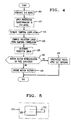
- FIG. 4 is a flow chart illustrating the functions performed by the centralized interactive graphics system of FIG. 1.
- FIG. 5 illustrates two objects contained within a single image frame.
- FIG. 6 illustrates a schematic diagram of sequential video frames on which temporal correlation measurements are performed.
- FIG. 7 illustrates a pair of sequential image blocks and the model motion vectors and block-based motion vector associated therewith.
- FIG. 8 illustrates an overlay of a current image block over a section of four image blocks from a previous image frame.
- FIG. 9 illustrates a block diagram of the video encoder of the video system of FIG. 1.
- FIG. 10 illustrates a block diagram illustrating the computer architecture for the centralized interactive graphics system of FIG. 2.
- FIG. 1 A general overview of a video system 10 incorporating the principles of an illustrative embodiment of the present invention is illustrated in FIG. 1.
- a plurality of display devices illustratively television receivers 12, are connected to network 14 by means of a cable 16.
- a set-top box (not shown) may be associated with each television 12 for transmitting and receiving instructions via the network 14.
- CGS interactive graphics system
- network 14 processes incoming requests from subscribers for services which may include interactive graphics services such as, for example, video games.
- the network 14 retrieves the requested video game from CIGS 18.
- the game is transmitted over cable 16 to the set- top box associated with the television receiver 12 of the subscriber requesting the video game.
- An input device 24, such as an air mouse, associated with each subscriber's television receiver 12 transmits instructions to the network 14 regarding the progression of the game.
- FIG. 2 shows CIGS 18 in more detail.
- a common database 225 is shared among the users and changes to the database 225 by each user are incorporated into the common database 225.
- This view-independent processing is shared among the users to reduce cost and latency in contrast with updating separate databases for each user.
- CIGS 18 includes a graphics engine front end 205, a hybrid rendering engine 210 and a video encoder backend 215 for each user.
- the graphics engine front end 205 generates data structures required for creating a particular 3-D scene.
- Each data structure comprises a group of mathematically described objects which are defined by points, lines, polygons and three dimensional solids. Using techniques well known in the art, details relating to each object's shape, texture and color values can also be defined.
- Each object is defined, relative to the other objects contained in the 3-D scene, by a matrix which includes information regarding rotation, scaling, shearing and translation.
- the processes performed by the graphics engine front end 205 are described in Computer Graphics: Principles and Practice , James D. Foley, et al., Addison Wesley, 1990.
- the hybrid rendering engine 210 performs conditional rendering on the 3-D objects, that is, transforming the data representing 3-D objects to data representing 2-D images.
- the 2-D images are incorporated into an image sequence which is comprised of a plurality of successive image frames which represent an animated 3-D scene. Adjacent image frames tend to be highly correlated due to small changes in object position and camera position during one frame time.
- Each image frame is comprised of a plurality of subunits or pixels.
- Each image frame is also subdivided into a plurality of image blocks each containing a predetermined number of pixels, e.g., 16 x 16 pixels.
- Motion vectors are generated for each image block which represent the projected direction of motion for any image of an object represented in the current image block and therefore predict the position of the image of the object in a subsequent image frame. Texture complexities which define spatial frequency energy associated with each region are also determined. The motion vectors and texture complexities for each image block are used to compute a prediction error which is accumulated over successive image frames. The prediction error is used to determine the type of encoding performed on each image block in successive image frames as will be described in detail hereinafter.
- the architecture for the system in FIG. 2 includes general and special purpose processors as illustrated in FIG. 10.
- Parallel general purpose processors are used to compute the model transformations, motion vectors, coding mode decisions and rate control parameters.
- High speed special purpose processors or ASIC's are used to perform scan conversion of textured polygons, DCT, DCT coefficient quantization and variable length coding, and data formatting of the coded video.
- the special purpose processing can reside on the system bus of a general purpose multiprocessor host computer 1010 with a separate digital video interface located between a scan converter 1015 and video encoder 1020.
- Low resolution rendering 305 is performed on the 3-D objects which includes applying a perspective transformation to the 3-D objects in which the objects undergo a series of mathematical transformations, as described below.
- the perspective transformation orients the objects in space relative to the viewer, scales the objects to the proper size, adjusts for perspective foreshortening, and clips the objects to the desired display volume (step 410).
- surface details which simulate color and texture, and shading details to simulate reflections of light.
- each object as defined by a given image frame, comprises a set of discrete points, each point comprising x,y,and z coordinates.
- Each image sequence represents the movement of objects in successive image frames.
- a temporal interframe correlation 310 is determined with respect to the position of each object contained in a current image frame relative to its position in the previous image frame (step 415).
- the temporal correlation is determined by the motion of each of the objects and the interframe visibility of the object.
- the information obtained from the temporal correlations is used for the encoding decision 315 which will be described in detail hereinafter.
- Intraframe visibility of an object depends firstly upon whether there is an overlap of the x,y coordinate positions of the images of one or more objects within the image frame. If there is an overlap of the x,y coordinates, illustratively the position of the z coordinate for the image of each object is considered to determine the visibility of the images of each of the objects.
- the z coordinate corresponds to depth. An image of an object having a greater z coordinate and, hence a greater depth, will be obscured by the image of an object having a smaller z coordinate if the images have overlap in x and y coordinates. In such a case, the image of the object having the smaller z coordinate at least partially blocks the view of the image of the other object.
- the objects can be drawn in a lower to higher priority ordering with higher priority objects being overwritten on lower priority objects. Generally higher priority objects represent "near" objects and lower priority objects represent "far" objects. Such a situation is illustrated in FIG. 5.
- FIG. 5 illustrates images of two objects 505, 510 displayed within an image frame 515. Part of image 510 is illustrated by a dashed line to indicate that the view of image 510 is partially obstructed by image 505. The dashed line also signifies that while both image 505 and image 510 have the same x and y coordinates within that defined area, image 510 has a greater z coordinate than image 505.
- FIG. 6 illustrates the motion of the image 605 of an object in two successive image frames 610, 615.
- Each matrix defines the transformation of the original object with respect to rotation, translation, scaling and shearing.
- a surface point 620 of the image 605 in the second frame 615 is correlated to the frame position in the first frame 610.
- a determination is made of whether the surface point 620 is positioned in the same corresponding frame position in the first frame 610 using the following equation: where
- Interframe visibility is an important component in determining temporal correlation. Interframe visibility is confirmed if an ID number associated with P t 1 equals an ID number associated with P t 2 . If the surface point 620 is the same thereby signifying movement of an object 605, the difference in x and y coordinate position is determined. The temporal correlation of a number of surface points contained in frame 615 relative to corresponding surface points contained in frame 610 are determined in the same manner.
- motion vectors can be generated from the temporal correlations for each surface point of the image. The motion vectors approximate the direction and rate of movement in a subsequent image frame.
- Model motion vectors are generated for each image block by sampling a number of the pixels contained in the block for a given image frame.
- the image block is illustratively a 16 x 16 pixel block. If the model motion vectors indicate that the image block represents a homogeneous region, i.e., that the model motion vectors are generally pointing in the same direction, the model motion vectors are averaged and the dominant vector, also referred to as the block-based motion vector, is used to represent the block.
- the number of pixels sampled in each block is determined by balancing considerations of computational efficiency and block-based motion vector accuracy.
- model motion vectors 720 for an image block 705 indicate that the block 705 contains more than one homogeneous region 710 and 715
- the model motion vectors 720 for each region 710 and 715 are averaged to obtain a region motion vector 725 and 730.
- a score S r is obtained for each region motion vector 725 and 730 using the above equation.
- the region motion vector within the 16 x 16 block which receives the highest score is determined to be the block based motion vector 740.
- a prediction error is computed for each block from the block based motion vector error (step 425 of FIG. 4).
- the prediction error for each block is computed based on the following relationship:
- the prediction errors for each image block are accumulated. If the accumulated prediction error for a given image block is below a predefined threshold, the block based motion vector for that image block is transmitted to the video encoder back end 215 of FIG. 2 which constructs the image block from the block based motion vector as described below (step 440 of FIG. 4). If the accumulated prediction error is above the predetermined threshold, the next image block is generated by the video encoder back end 215 which encodes the block as described below (step 435). In this case, the prediction error for this block is set to zero for the purpose of prediction error accumulation in the next frame.
- the video encoder back end 215 follows the MPEG (Coding of Moving Pictures and Associated Audio) standard which is well known in the art and is described in Video Draft Editing Committee, "Generic Coding of Moving Pictures and Associated Audio,” Recommendation H.262, ISO/IEC 13818-2, Committee Draft for Video, Seoul, Nov. 1993 and "ISO CD 11172-2: Coding of Moving Pictures and Associated Audio for Digital Storage Media at up to about 1.5 Mbits/s," Nov. 1991.
- the MPEG standard encoding incorporates predictive encoding techniques which include the use of both intrablock and interblock coding techniques in combination with the discrete cosine transform, adaptive coefficient quantization, run length encoding and statistical or Huffman encoding.
- Intrablock encoding does not use temporal prediction (motion compensation) but only uses information contained in the current frame to encode a given image block.
- Interframe encoding is the generation of encoded block data from, for example, the differences between information from a current source block and a block predicted from prior blocks.
- the MPEG standard incorporates two basic types of interblock encoding. The first develops predictive blocks, referred to as "P" blocks, from the current block and a prior block. The second develops bidirectionally predictive blocks, referred to as "B" blocks, from the current block and a prior or a subsequent block. Blocks which are intrablock encoded are referred to as "I" blocks.
- Other types of predictive encoding techniques may be employed by the video encoder back end 215 without departing from the scope and spirit of the present invention.
- the MPEG encoding is determined on a block by block basis, where each block has the dimensions of 16 x 16 pixels.
- I blocks, P blocks, and B blocks can be generated based on the prediction error determination of the graphics generator.
- the current block is copied from the previous frame using the block based motion vector.
- the motion vector can refer to a past or future frame, or both with averaging.
- the video encoder back end 215 generates P block or B blocks based on the transmitted motion vectors.
- the video encoder back end When the accumulated prediction error is above the threshold, the video encoder back end generates an I block and the accumulated prediction error is set to zero.
- the rate at which I-blocks are generated is limited by the capacity of the renderer and by the maximum bit-rate allowed for the transmission of coded video. This necessitates the use of a rate control mechanism which limits the number of I-blocks per frame.
- the I-block rate is periodically monitored during a frame time and the PE threshold is adjusted to achieve a target I-block rate. The I-block rate and threshold are further adjusted down and up respectively if the coded video buffer becomes too full.
- FIG. 9 illustrates the video encoder back end 215 of FIG. 2 in more detail.
- the video encoder back end 215 generally performs the same encoding functions as is performed in a conventional video encoder once the encoding type decision for each image block has been determined.
- a discrete cosine transform (DCT) circuit 905 develops sets of 8 x 8 frequency domain coefficients.
- Adaptive quantizer 910 quantizes the transformed coefficients.
- a formatter 915 performs variable length encoding of the generated DCT coefficients thereby producing variable length encoded codewords.
- the codewords are then formatted with the appropriate header information in order to facilitate decoding by the receiver.
- the motion vector information is also received by the formatter 915.
- DCT discrete cosine transform
- the coded data is transmitted to bit buffer 920 which transmits the encoded data to television receiver 12.
- bit buffer 920 which transmits the encoded data to television receiver 12.
- Additional coding and rendering efficiency can be obtained by approximating the effect of changes in illumination or shading, or partial occlusion of a region with a partially transparent object.
- Changes in shading can be approximated by adding or subtracting from the lowest order or 0,0 DCT coefficient for a given block of luminance DCT coefficients.
- Changes in the color of illumination require that both luminance and chrominance 0,0 coefficients be offset. The effect of this is to offset the average value of the corresponding blocks of pixels.
- the effect of partial occlusion by a non-textured and partially transparent object can be approximated by applying an offset to both luminance and chrominance 0,0 DCT coefficients.
- the latency of the system is significantly reduced.
- the approximation techniques traditionally performed by the video encoder used to determine the type of encoding to be performed are computationally intensive. Since these computations are now part of the rendering process, the latency in the overall system is reduced, and more importantly the overall system hardware complexity is reduced which lowers the cost of the system.
Abstract
Description
- The present invention relates to computer graphics systems for generating video images.
- Computer animation is a term used to describe any application in which a computer aids in the generation and manipulation of a sequence of changing images. Computer animation is widely used in industry, science, manufacturing, entertainment, advertising and education. Examples of computer animation applications are computer aided design (CAD), flight simulation and video games.
- Certain high performance interactive graphics systems, such as computer workstations, flight simulators and other types of video systems, require complex three-dimensional (3-D) rendering programs to generate realistic two-dimensional (2-D) images of animated 3-D graphics scenes. Essentially, the task of a rendering program is to transform a 3-D geometric model, stored as a computational representation of objects, into a 2-D image displayable on a computer display.
- The relative positions of image components create a perspective for the viewer, and the appearance of three dimensions. Successive 2-D image frames create the illusion of movement within the reproduced scene. Many times these 2-D images are used in applications which also require interactivity by the user. For many of these interactive applications, computer animation having real-time response is highly desirable.
- For example, with the advent of interactive television systems comes the desire to provide services, such as video games, which allow the subscriber to interact with the system or other subscribers to the system. Because each subscriber can interact with the system independently from other subscribers, each subscriber's perspective of the generated image sequences is different. The subscriber's perspective may be dependent on factors, such as the position and direction of view in which a subscriber is looking, the type of screen on which the images are displayed, the degree of action portrayed by the images and the number of subscribers interacting with the particular application. As such, a separate set of video signals must be generated for each subscriber which accurately represents the particular subscriber's perspective of the images. Using current technology, a graphics generator and a separate video encoder would be used to generate each set of video signals.
- The costs involved in providing each subscriber with his own graphics generator and video encoder are economically unattractive. Another concern is the latency of the system. Latency is the time required for the system to begin display of the desired video signal once the user input is received. Latency is caused by certain functions performed by the video encoder, such as motion approximation, prediction error computations, and buffer size requirements, which comprise a large percentage of the amount of time required to encode the images of the 3-D models. If the latency is too great, real time response is not possible. It would be desirable to reduce the latency and cost of the system by providing an interactive system which is capable of generating compressed video signals without requiring a separate graphics generator and video encoder for each subscriber.
- The present invention is directed to such an interactive system. We have recognized that some of the rendering functions conventionally performed by a graphics generator and the encoding functions conventionally performed by a video encoder can be combined in a hybrid system which is capable of computing and encoding information during the rendering of the image frames needed to generate compressed video signals.
- In accordance with the present invention, a hybrid system for synthesizing a compressed video bitstream from a dynamic 3-D model has been realized. The video bitstream represents an image sequence comprised of a plurality of image frames which are sequential in time and in which each image frame is partitioned into a set of regions. Motion vectors are generated for each region within a current image frame which represent the dynamic 3-D model. A prediction error is computed for each region based on the generated motion vectors. The type of encoding to be performed on each region in a succeeding image frame is determined based on the value of the prediction error. Each region in the succeeding image frame is encoded as indicated by the determined encoding type.
- By determining the type of video encoding to be performed on each region within an image frame during the rendering of the region, the latency of the system is significantly reduced. The approximation techniques traditionally performed by the video encoder used to determine the type of encoding to be performed are computationally intensive. Since these computations are now part of the rendering process, the latency in the overall system is reduced, and more importantly, the overall system hardware complexity is also reduced which reduces the cost of the system.
- The hybrid system also allows for the creation of a centralized interactive graphics system which is capable of remotely generating images of 3-D scenes on each viewer's screen. A centralized system also reduces costs by timesharing the hardware among all of the subscribers.
- FIG. 1 illustrates a schematic diagram of a video system implemented in accordance with an illustrative embodiment of the present invention.
- FIG. 2 illustrates a block diagram of the centralized interactive graphics system of FIG. 1.
- FIG. 3 illustrates a block diagram of the hybrid renderer engine of FIG. 2.
- FIG. 4 is a flow chart illustrating the functions performed by the centralized interactive graphics system of FIG. 1.
- FIG. 5 illustrates two objects contained within a single image frame.
- FIG. 6 illustrates a schematic diagram of sequential video frames on which temporal correlation measurements are performed.
- FIG. 7 illustrates a pair of sequential image blocks and the model motion vectors and block-based motion vector associated therewith.
- FIG. 8 illustrates an overlay of a current image block over a section of four image blocks from a previous image frame.
- FIG. 9 illustrates a block diagram of the video encoder of the video system of FIG. 1.
- FIG. 10 illustrates a block diagram illustrating the computer architecture for the centralized interactive graphics system of FIG. 2.
- A general overview of a
video system 10 incorporating the principles of an illustrative embodiment of the present invention is illustrated in FIG. 1. A plurality of display devices,illustratively television receivers 12, are connected tonetwork 14 by means of acable 16. A set-top box (not shown) may be associated with eachtelevision 12 for transmitting and receiving instructions via thenetwork 14. A centralized interactive graphics system (CIGS) 18, also associated withnetwork 14, is capable of generating computer graphics. - In operation,
network 14 processes incoming requests from subscribers for services which may include interactive graphics services such as, for example, video games. Thenetwork 14 retrieves the requested video game from CIGS 18. The game is transmitted overcable 16 to the set- top box associated with thetelevision receiver 12 of the subscriber requesting the video game. Aninput device 24, such as an air mouse, associated with each subscriber'stelevision receiver 12 transmits instructions to thenetwork 14 regarding the progression of the game. - FIG. 2 shows CIGS 18 in more detail. In a multiuser game, a
common database 225 is shared among the users and changes to thedatabase 225 by each user are incorporated into thecommon database 225. This view-independent processing is shared among the users to reduce cost and latency in contrast with updating separate databases for each user. CIGS 18 includes a graphicsengine front end 205, ahybrid rendering engine 210 and avideo encoder backend 215 for each user. The graphicsengine front end 205 generates data structures required for creating a particular 3-D scene. Each data structure comprises a group of mathematically described objects which are defined by points, lines, polygons and three dimensional solids. Using techniques well known in the art, details relating to each object's shape, texture and color values can also be defined. Each object, in turn, is defined, relative to the other objects contained in the 3-D scene, by a matrix which includes information regarding rotation, scaling, shearing and translation. The processes performed by the graphicsengine front end 205 are described in Computer Graphics: Principles and Practice, James D. Foley, et al., Addison Wesley, 1990. - The
hybrid rendering engine 210 performs conditional rendering on the 3-D objects, that is, transforming the data representing 3-D objects to data representing 2-D images. The 2-D images are incorporated into an image sequence which is comprised of a plurality of successive image frames which represent an animated 3-D scene. Adjacent image frames tend to be highly correlated due to small changes in object position and camera position during one frame time. Each image frame is comprised of a plurality of subunits or pixels. Each image frame is also subdivided into a plurality of image blocks each containing a predetermined number of pixels, e.g., 16 x 16 pixels. - Motion vectors are generated for each image block which represent the projected direction of motion for any image of an object represented in the current image block and therefore predict the position of the image of the object in a subsequent image frame. Texture complexities which define spatial frequency energy associated with each region are also determined. The motion vectors and texture complexities for each image block are used to compute a prediction error which is accumulated over successive image frames. The prediction error is used to determine the type of encoding performed on each image block in successive image frames as will be described in detail hereinafter. Once the
hybrid rendering engine 210 has determined the type of encoding to be performed on a successive image block, the decision is transmitted to the video encoderback end 215 which encodes the motion vector or image block and transmits the encoded motion vector or image block to thetelevision receiver 12 of FIG. 1. - The architecture for the system in FIG. 2 includes general and special purpose processors as illustrated in FIG. 10. Parallel general purpose processors are used to compute the model transformations, motion vectors, coding mode decisions and rate control parameters. High speed special purpose processors or ASIC's are used to perform scan conversion of textured polygons, DCT, DCT coefficient quantization and variable length coding, and data formatting of the coded video. The special purpose processing can reside on the system bus of a general purpose
multiprocessor host computer 1010 with a separate digital video interface located between ascan converter 1015 andvideo encoder 1020. - Referring to FIGs. 3 and 4, the
hybrid rendering engine 210 will be described in more detail. Low resolution rendering 305 is performed on the 3-D objects which includes applying a perspective transformation to the 3-D objects in which the objects undergo a series of mathematical transformations, as described below. The perspective transformation orients the objects in space relative to the viewer, scales the objects to the proper size, adjusts for perspective foreshortening, and clips the objects to the desired display volume (step 410). Also included in the transformations are surface details which simulate color and texture, and shading details to simulate reflections of light. By performing these transformations, a mapping definition is derived for each object to produce a 2-D image. - In general, each object, as defined by a given image frame, comprises a set of discrete points, each point comprising x,y,and z coordinates. Each image sequence represents the movement of objects in successive image frames. Prior to generating each successive image frame, a
temporal interframe correlation 310 is determined with respect to the position of each object contained in a current image frame relative to its position in the previous image frame (step 415). The temporal correlation is determined by the motion of each of the objects and the interframe visibility of the object. The information obtained from the temporal correlations is used for theencoding decision 315 which will be described in detail hereinafter. - Intraframe visibility of an object depends firstly upon whether there is an overlap of the x,y coordinate positions of the images of one or more objects within the image frame. If there is an overlap of the x,y coordinates, illustratively the position of the z coordinate for the image of each object is considered to determine the visibility of the images of each of the objects. In an image space representation, the z coordinate corresponds to depth. An image of an object having a greater z coordinate and, hence a greater depth, will be obscured by the image of an object having a smaller z coordinate if the images have overlap in x and y coordinates. In such a case, the image of the object having the smaller z coordinate at least partially blocks the view of the image of the other object. Alternatively, the objects can be drawn in a lower to higher priority ordering with higher priority objects being overwritten on lower priority objects. Generally higher priority objects represent "near" objects and lower priority objects represent "far" objects. Such a situation is illustrated in FIG. 5.
- FIG. 5 illustrates images of two
objects image frame 515. Part ofimage 510 is illustrated by a dashed line to indicate that the view ofimage 510 is partially obstructed byimage 505. The dashed line also signifies that while bothimage 505 andimage 510 have the same x and y coordinates within that defined area,image 510 has a greater z coordinate thanimage 505. - FIG. 6 illustrates the motion of the
image 605 of an object in two successive image frames 610, 615. A matrix Mt₁ is used to represent the position of theimage 605 in thefirst frame 610 at time t=1. A second matrix Mt₂ is used to represent the position of theimage 605 in thesecond frame 615 at time t=2. Each matrix defines the transformation of the original object with respect to rotation, translation, scaling and shearing. Asurface point 620 of theimage 605 in thesecond frame 615 is correlated to the frame position in thefirst frame 610. A determination is made of whether thesurface point 620 is positioned in the same corresponding frame position in thefirst frame 610 using the following equation:
where - Pt
1 - = surface point of image at t=1
- Pt
2 - = surface point of image at t=2
- Mt
2 ⁻¹ - = inverse of matrix used to represent image at t=2.
- Mt
1 - = matrix used to represent image at t=1.
- proj
- = division by homogeneous coordinate W
- Interframe visibility is an important component in determining temporal correlation. Interframe visibility is confirmed if an ID number associated with Pt
1 equals an ID number associated with Pt2 . If thesurface point 620 is the same thereby signifying movement of anobject 605, the difference in x and y coordinate position is determined. The temporal correlation of a number of surface points contained inframe 615 relative to corresponding surface points contained inframe 610 are determined in the same manner. - If a portion of an image of an object is visible in the current image frame but obstructed in the previous image frame, temporal correlation of the surface points is not defined. In such a case, the pixels representing that portion of the image would soon have to be synthesized from the original 3-D model to avoid visible error. However, in the case where an image of an object is visible both in the current image frame and the previous image frame, the movement of the image in a subsequent image frame can be approximated using motion vectors (step 420). Motion vectors can be generated from the temporal correlations for each surface point of the image. The motion vectors approximate the direction and rate of movement in a subsequent image frame.
- Model motion vectors are generated for each image block by sampling a number of the pixels contained in the block for a given image frame. The image block is illustratively a 16 x 16 pixel block. If the model motion vectors indicate that the image block represents a homogeneous region, i.e., that the model motion vectors are generally pointing in the same direction, the model motion vectors are averaged and the dominant vector, also referred to as the block-based motion vector, is used to represent the block. The number of pixels sampled in each block is determined by balancing considerations of computational efficiency and block-based motion vector accuracy.
- As illustrated in FIG. 7, if
model motion vectors 720 for animage block 705 indicate that theblock 705 contains more than onehomogeneous region model motion vectors 720 are weighted based on the size of eachregion region 
where - Sr
- = score for region r
- Ar
- = area of region r
- Tr
- = texture complexity associated with each region r
- Mr
- = degree of motion vector similarity within region r

- The
model motion vectors 720 for eachregion region motion vector region motion vector motion vector 740. - Once the block based motion vectors are generated for each image block contained in the image frame, a prediction error is computed for each block from the block based motion vector error (step 425 of FIG. 4). The prediction error for each block is computed based on the following relationship:

where - PEb
- = prediction error for a given block
- Tr
- = texture complexity of region r
- MVmodel
- = model motion vector
- MVblock
- = value of block-based motion vector
- Pi
- = prediction error for current image block
- w₁+w₂+w₃+w₄
- = 1 (normalized)
- As successive image frames are generated, the prediction errors for each image block are accumulated. If the accumulated prediction error for a given image block is below a predefined threshold, the block based motion vector for that image block is transmitted to the video encoder
back end 215 of FIG. 2 which constructs the image block from the block based motion vector as described below (step 440 of FIG. 4). If the accumulated prediction error is above the predetermined threshold, the next image block is generated by the video encoderback end 215 which encodes the block as described below (step 435). In this case, the prediction error for this block is set to zero for the purpose of prediction error accumulation in the next frame. - In preferred embodiments, the video encoder
back end 215 follows the MPEG (Coding of Moving Pictures and Associated Audio) standard which is well known in the art and is described in Video Draft Editing Committee, "Generic Coding of Moving Pictures and Associated Audio," Recommendation H.262, ISO/IEC 13818-2, Committee Draft for Video, Seoul, Nov. 1993 and "ISO CD 11172-2: Coding of Moving Pictures and Associated Audio for Digital Storage Media at up to about 1.5 Mbits/s," Nov. 1991. The MPEG standard encoding incorporates predictive encoding techniques which include the use of both intrablock and interblock coding techniques in combination with the discrete cosine transform, adaptive coefficient quantization, run length encoding and statistical or Huffman encoding. Intrablock encoding does not use temporal prediction (motion compensation) but only uses information contained in the current frame to encode a given image block. Interframe encoding is the generation of encoded block data from, for example, the differences between information from a current source block and a block predicted from prior blocks. The MPEG standard incorporates two basic types of interblock encoding. The first develops predictive blocks, referred to as "P" blocks, from the current block and a prior block. The second develops bidirectionally predictive blocks, referred to as "B" blocks, from the current block and a prior or a subsequent block. Blocks which are intrablock encoded are referred to as "I" blocks. Other types of predictive encoding techniques may be employed by the video encoderback end 215 without departing from the scope and spirit of the present invention. - In accordance with the present invention, the MPEG encoding is determined on a block by block basis, where each block has the dimensions of 16 x 16 pixels. As such, I blocks, P blocks, and B blocks can be generated based on the prediction error determination of the graphics generator. When the accumulated prediction error falls below the threshold as described above, the current block is copied from the previous frame using the block based motion vector. In the case of B blocks, the motion vector can refer to a past or future frame, or both with averaging. Accordingly, the video encoder
back end 215 generates P block or B blocks based on the transmitted motion vectors. When the accumulated prediction error is above the threshold, the video encoder back end generates an I block and the accumulated prediction error is set to zero. - The rate at which I-blocks are generated is limited by the capacity of the renderer and by the maximum bit-rate allowed for the transmission of coded video. This necessitates the use of a rate control mechanism which limits the number of I-blocks per frame. Typically the I-block rate is periodically monitored during a frame time and the PE threshold is adjusted to achieve a target I-block rate. The I-block rate and threshold are further adjusted down and up respectively if the coded video buffer becomes too full.
- FIG. 9 illustrates the video encoder
back end 215 of FIG. 2 in more detail. The video encoderback end 215 generally performs the same encoding functions as is performed in a conventional video encoder once the encoding type decision for each image block has been determined. A discrete cosine transform (DCT)circuit 905 develops sets of 8 x 8 frequency domain coefficients.Adaptive quantizer 910 quantizes the transformed coefficients. Aformatter 915 performs variable length encoding of the generated DCT coefficients thereby producing variable length encoded codewords. The codewords are then formatted with the appropriate header information in order to facilitate decoding by the receiver. The motion vector information is also received by theformatter 915. The coded data is transmitted to bit buffer 920 which transmits the encoded data totelevision receiver 12. Each of the elements of the video encoderback end 215 are described more fully in commonly assigned U.S. Patent 5,144,423 issued to Knauer et. al. on September 1, 1992, and incorporated herein by reference. - Additional coding and rendering efficiency can be obtained by approximating the effect of changes in illumination or shading, or partial occlusion of a region with a partially transparent object. Changes in shading can be approximated by adding or subtracting from the lowest order or 0,0 DCT coefficient for a given block of luminance DCT coefficients. Changes in the color of illumination require that both luminance and chrominance 0,0 coefficients be offset. The effect of this is to offset the average value of the corresponding blocks of pixels. The effect of partial occlusion by a non-textured and partially transparent object can be approximated by applying an offset to both luminance and chrominance 0,0 DCT coefficients.
- By determining the type of video encoding to be performed on each region within an image frame during the rendering of the region and using block-based motion vectors to compute prediction error, the latency of the system is significantly reduced. The approximation techniques traditionally performed by the video encoder used to determine the type of encoding to be performed are computationally intensive. Since these computations are now part of the rendering process, the latency in the overall system is reduced, and more importantly the overall system hardware complexity is reduced which lowers the cost of the system.
- It will be appreciated that those skilled in the art will be able to devise numerous and various alternative arrangements which, although not explicitly shown or described herein, embody the principles of the invention and are within its scope and spirit.
Typically, an image block for a current image frame overlaps four image blocks of a previous image frame as illustrated in FIG. 8.
where
The total prediction error for the
Claims (34)
- A hybrid system for synthesizing a compressed video bitstream from a dynamic 3-D model, said video bitstream representing an image sequence comprised of a plurality of image frames which are sequential in time, each image frame being partitioned into a set of nonoverlapping contiguous regions, each block of said image frame being encoded as indicated by a predictive encoding type, the method comprising the steps of:
means for generating motion vectors for each region within a current image frame representing the dynamic 3-D model;
means for computing a prediction error for each region based on the generated motion vectors;
means for determining a type of predictive encoding to be performed on each region in a succeeding image frame based on the value of the prediction error; and
means for encoding each region in the succeeding image frame as indicated by the determined predictive encoding type. - The system according to claim 1 wherein each region is a rectangular block and wherein said step of generating motion vectors comprises:
means for receiving a dynamic 3-D geometric model;
means for computing model motion vectors from the dynamic 3-D model; and
means for using block-based motion vectors to approximate said model motion vectors. - The system according to claim 2 wherein the model motion vectors are computed at less than display resolution.
- The system according to claim 3 wherein said means for using said block-based motion vectors to approximate the model motion vectors further comprises:
means for determining a weighted average of the model motion vectors contained within each block of the image frame; and
means for representing the weighted averaged model motion vectors by a single block-based motion vector. - The system according to claim 4 wherein the weighted averaging of the model motion vectors within a given block is a function of the area and texture complexity of each homogeneous region within the block.
- The system according to claim 2 wherein said predictive encoding type includes predictive interblock encoding.
- The system according to claim 6 wherein said predictive interblock encoding is bidirectional.
- A method of synthesizing a compressed video bitstream from a dynamic 3-D model, said video bitstream representing an image sequence comprised of a plurality of image frames which are sequential in time, each image frame being partitioned into a set of non-overlapping contiguous regions, each block of said image frame being encoded as indicated by a predictive encoding type, the method comprising the steps of:
generating motion vectors for each region within a current image frame representing the dynamic 3-D model;
computing a prediction error for each region based on the generated motion vectors;
determining a type of predictive encoding to be performed on each region in a succeeding image frame based on the value of the prediction error; and
encoding each region in the succeeding image frame as indicated by the determined encoding type. - The method according to claim 8 wherein each region is a rectangular block, and wherein the step of generating motion vectors comprises steps of:
receiving a dynamic 3-D geometric model;
computing model motion vectors from the dynamic 3-D model; and
using block-based motion vectors to approximate the model motion vectors. - The method according to claim 9 wherein said step of using the block-based motion vectors to approximate the model motion vectors comprises the steps of:
determining a weighted average of the model motion vectors contained within each block of the image frame; and
representing the weighted averaged model motion vectors by a single block-based motion vector. - The method according to claim 10 wherein said predictive encoding type includes predictive interblock encoding.
- The method according to claim 11 wherein said predictive interblock encoding is bidirectional.
- A system for synthesizing an image sequence from a dynamic 3-D model, said image sequence comprised of a plurality of image frames which are sequential in time, each image frame being partitioned into a set of contiguous rectangular blocks, the system comprising:
means for receiving a dynamic 3-D geometric model;
means for computing model motion vectors from the dynamic 3-D model; and
means for approximating said model motion vectors using block-based motion vectors. - The system according to claim 13 wherein the model motion vectors are computed at less than display resolution.
- The system according to claim 14 wherein said means for approximating model motion vectors further comprises:
means for determining a weighted average of the model motion vectors contained within each block of the image frame; and
means for representing the weighted averaged model motion vectors by a single block-based motion vector. - The system according to claim 15 wherein the weighted averaging of the model motion vectors within a given block is a function of the area and texture complexity of each homogeneous region within the block.
- The system according to claim 13 further comprising:
means for computing prediction errors associated with each block-based motion vector; and
means for accumulating the prediction errors over a plurality of image frames. - The system according to claim 17 wherein said accumulating means further comprises:
means for determining an area-weighted average for each block. - The system according to claim 18 further comprising:
means for approximating a change in illumination of a given block by adjusting the 0,0 DCT coefficients. - The system according to claim 18 further comprising:
means for approximating a partial occlusion of a block with a partially transparent nontextural block by adjusting the 0,0 DCT coefficients. - The method according to claim 11 further comprising the steps of:
computing prediction errors associated with each block-based motion vector; and
accumulating the prediction errors over a plurality of image frames. - The system according to claim 21 wherein said encoding means further comprises:
means for comparing said accumulated prediction errors to a threshold; and
means for synthesizing the block associated with a particular accumulated prediction error if the particular accumulated prediction error exceeds the threshold. - The system according to claim 22 further comprising:
means for controlling the rate of block synthesis by adjusting the threshold. - A method of synthesizing an image sequence from a dynamic 3-D model, said image sequence comprised of a plurality of image frames which are sequential in time, each image frame being partitioned into a set of contiguous rectangular blocks, the method comprising the steps of:
receiving a dynamic 3-D geometric model;
computing model motion vectors from the dynamic 3-D model; and
approximating the model motion vectors using block-based motion vectors. - The method according to claim 24 wherein said step of approximating model motion vectors comprises the steps of:
determining a weighted average of the model motion vectors contained within each block of the image frame; and
representing the weighted averaged model motion vectors by a single block-based motion vector. - The method according to claim 25 further comprising the steps of:
computing prediction errors associated with each block-based motion vector; and
accumulating the prediction errors over a plurality of image frames. - The method according to claim 26 wherein said step of accumulating prediction errors further comprises the step of:
determining an area-weighted average for each block. - The method according to claim 27 further comprising the step of:
approximating a change in illumination of a given block by adjusting the 0,0 DCT coefficients. - The method according to claim 27 further comprising the step of:
approximating a partial occlusion of a block with a partially transparent nontextural block by adjusting the 0,0 DCT coefficients. - The method according to claim 29 further comprising the steps of:
determining a type of predictive encoding to be performed on each block in a succeeding image frame based on the value of the prediction error; and
encoding each block in the succeeding image frame as indicated by the determined predictive encoding type. - The method according to claim 30 further comprising the steps of:
comparing said accumulated prediction errors to a threshold; and
synthesizing the block associated with a particular accumulated prediction error if the particular accumulated prediction error exceeds the threshold. - The method according to claim 31 further comprising the step of:
controlling the rate of block synthesis by adjusting the threshold. - A method of synthesizing a compressed video bitstream from a dynamic 3-D model, said video bitstream representing an image sequence comprised of a plurality of image frames which are sequential in time, each image frame being partitioned into a set of contiguous rectangular blocks, the method comprising the steps of:
receiving a dynamic 3-D geometric model;
computing model motion vectors from the dynamic 3-D model;
approximating model motion vectors using block-based motion vectors;
computing prediction errors associated with each block-based motion vector;
accumulating the prediction errors over a plurality of image frames
comparing said accumulated prediction errors to a threshold;
synthesizing the block associated with a particular accumulated prediction error if the particular accumulated prediction error exceeds the threshold;
generating a block associated with a particular accumulated prediction error which is less than the threshold from a block from a previous image frame; and
transmitting the synthesized blocks to a video encoder. - The system according to claim 33 further comprising:
controlling the rate of block synthesis by adjusting the threshold.
Applications Claiming Priority (2)
| Application Number | Priority Date | Filing Date | Title |
|---|---|---|---|
| US22173294A | 1994-04-01 | 1994-04-01 | |
| US221732 | 1994-04-01 |
Publications (3)
| Publication Number | Publication Date |
|---|---|
| EP0675462A2 true EP0675462A2 (en) | 1995-10-04 |
| EP0675462A3 EP0675462A3 (en) | 1997-03-12 |
| EP0675462B1 EP0675462B1 (en) | 2000-09-27 |
Family
ID=22829121
Family Applications (1)
| Application Number | Title | Priority Date | Filing Date |
|---|---|---|---|
| EP95301882A Expired - Lifetime EP0675462B1 (en) | 1994-04-01 | 1995-03-21 | System and method of generating compressed video graphics images |
Country Status (6)
| Country | Link |
|---|---|
| US (1) | US5742289A (en) |
| EP (1) | EP0675462B1 (en) |
| JP (1) | JP3229162B2 (en) |
| KR (1) | KR100361398B1 (en) |
| CA (1) | CA2144253C (en) |
| DE (1) | DE69518937T2 (en) |
Cited By (8)
| Publication number | Priority date | Publication date | Assignee | Title |
|---|---|---|---|---|
| WO1999023831A2 (en) | 1997-11-04 | 1999-05-14 | Koninklijke Philips Electronics N.V. | Methods and apparatus for processing dvd video |
| EP1037167A2 (en) * | 1999-03-15 | 2000-09-20 | Sun Microsystems, Inc. | System and method for generating and playback of three-dimensional movies |
| CN1099656C (en) * | 1996-11-28 | 2003-01-22 | 汤姆森多媒体公司 | Method and device for video compression |
| WO2003105482A1 (en) * | 2002-06-11 | 2003-12-18 | Sony Computer Entertainment Inc. | System and method for compression of 3d computer graphics |
| EP1496704A1 (en) * | 2003-07-07 | 2005-01-12 | STMicroelectronics S.r.l. | Graphic system comprising a pipelined graphic engine, pipelining method and computer program product |
| EP2238764A1 (en) * | 2008-01-25 | 2010-10-13 | Hewlett-Packard Company | Coding mode selection for block-based encoding |
| CN102055982A (en) * | 2011-01-13 | 2011-05-11 | 浙江大学 | Coding and decoding methods and devices for three-dimensional video |
| EP2384001A1 (en) * | 2010-04-29 | 2011-11-02 | Alcatel Lucent | Providing of encoded video applications in a network environment |
Families Citing this family (97)
| Publication number | Priority date | Publication date | Assignee | Title |
|---|---|---|---|---|
| US8352400B2 (en) | 1991-12-23 | 2013-01-08 | Hoffberg Steven M | Adaptive pattern recognition based controller apparatus and method and human-factored interface therefore |
| JP2907089B2 (en) * | 1996-01-11 | 1999-06-21 | 日本電気株式会社 | Interactive video presentation device |
| US6654414B1 (en) * | 1996-11-12 | 2003-11-25 | Ibm Corporation | Video conferencing using camera environment panoramas |
| US5990959A (en) * | 1996-12-20 | 1999-11-23 | U S West, Inc. | Method, system and product for direct rendering of video images to a video data stream |
| US6304607B1 (en) * | 1997-03-18 | 2001-10-16 | Texas Instruments Incorporated | Error resilient video coding using reversible variable length codes (RVLCS) |
| EP0925557B1 (en) * | 1997-07-11 | 2003-10-01 | Koninklijke Philips Electronics N.V. | Audiovisual data decoding method |
| FR2765984B1 (en) * | 1997-07-11 | 1999-10-22 | France Telecom | SIGNAL OF ANIMATION DATA OF A QUANTIFYING GRAPHIC SCENE, CORRESPONDING METHOD AND DEVICE |
| AU9808298A (en) * | 1997-10-15 | 1999-05-03 | Electric Planet, Inc. | A system and method for generating an animatable character |
| US5969772A (en) * | 1997-10-30 | 1999-10-19 | Nec Corporation | Detection of moving objects in video data by block matching to derive a region motion vector |
| AU3804999A (en) * | 1998-05-11 | 1999-11-29 | University Of British Columbia, The | Method and system for mpeg-2 encoding with frame partitioning |
| EP0973129A3 (en) | 1998-07-17 | 2005-01-12 | Matsushita Electric Industrial Co., Ltd. | Motion image data compression system |
| US6489995B1 (en) * | 1998-10-22 | 2002-12-03 | Sony Corporation | Method and apparatus for motion vector concealment |
| US7966078B2 (en) | 1999-02-01 | 2011-06-21 | Steven Hoffberg | Network media appliance system and method |
| AU3700300A (en) * | 1999-02-16 | 2000-09-04 | Shells Interactive, Ltd. | Compression system |
| US7779406B2 (en) * | 1999-04-16 | 2010-08-17 | Microsoft Corporation | Method and system for managing lifecycles of deployed applications |
| US6330281B1 (en) | 1999-08-06 | 2001-12-11 | Richfx Ltd. | Model-based view extrapolation for interactive virtual reality systems |
| WO2001074082A1 (en) * | 2000-03-27 | 2001-10-04 | Teranex, Inc. | Temporal interpolation of interlaced or progressive video images |
| US20060036756A1 (en) | 2000-04-28 | 2006-02-16 | Thomas Driemeyer | Scalable, multi-user server and method for rendering images from interactively customizable scene information |
| JP2002163678A (en) * | 2000-09-13 | 2002-06-07 | Monolith Co Ltd | Method and device for generating pseudo three- dimensional image |
| EP1199895B1 (en) * | 2000-10-20 | 2005-09-14 | Samsung Electronics Co., Ltd. | Encoding/decoding apparatus and method for orientation interpolator node data |
| CA2359260C (en) * | 2000-10-20 | 2004-07-20 | Samsung Electronics Co., Ltd. | Coding apparatus and method for orientation interpolator node |
| KR100590522B1 (en) * | 2000-10-20 | 2006-06-15 | 삼성전자주식회사 | Coding apparatus and method for orientation interpolator node |
| US7587520B1 (en) | 2001-01-24 | 2009-09-08 | 3Dlabs Inc. Ltd. | Image display system with visual server |
| US8243803B2 (en) * | 2001-11-30 | 2012-08-14 | Ntt Docomo, Inc. | Moving picture coding apparatus, moving picture decoding apparatus, moving picture coding method, moving picture decoding method, program, and computer-readable recording medium containing the program |
| US7916147B2 (en) | 2002-03-01 | 2011-03-29 | T5 Labs Ltd. | Centralised interactive graphical application server |
| PT1467491E (en) * | 2002-05-02 | 2007-03-30 | Fraunhofer Ges Forschung | Arithmetical coding of transform coefficients |
| US8468575B2 (en) * | 2002-12-10 | 2013-06-18 | Ol2, Inc. | System for recursive recombination of streaming interactive video |
| US9192859B2 (en) | 2002-12-10 | 2015-11-24 | Sony Computer Entertainment America Llc | System and method for compressing video based on latency measurements and other feedback |
| US9314691B2 (en) * | 2002-12-10 | 2016-04-19 | Sony Computer Entertainment America Llc | System and method for compressing video frames or portions thereof based on feedback information from a client device |
| US9003461B2 (en) * | 2002-12-10 | 2015-04-07 | Ol2, Inc. | Streaming interactive video integrated with recorded video segments |
| US8832772B2 (en) * | 2002-12-10 | 2014-09-09 | Ol2, Inc. | System for combining recorded application state with application streaming interactive video output |
| US20110126255A1 (en) * | 2002-12-10 | 2011-05-26 | Onlive, Inc. | System and method for remote-hosted video effects |
| US7558525B2 (en) * | 2002-12-10 | 2009-07-07 | Onlive, Inc. | Mass storage repository for a wireless network |
| US20090118019A1 (en) * | 2002-12-10 | 2009-05-07 | Onlive, Inc. | System for streaming databases serving real-time applications used through streaming interactive video |
| US10201760B2 (en) * | 2002-12-10 | 2019-02-12 | Sony Interactive Entertainment America Llc | System and method for compressing video based on detected intraframe motion |
| US9032465B2 (en) | 2002-12-10 | 2015-05-12 | Ol2, Inc. | Method for multicasting views of real-time streaming interactive video |
| US8526490B2 (en) * | 2002-12-10 | 2013-09-03 | Ol2, Inc. | System and method for video compression using feedback including data related to the successful receipt of video content |
| US8840475B2 (en) * | 2002-12-10 | 2014-09-23 | Ol2, Inc. | Method for user session transitioning among streaming interactive video servers |
| US9108107B2 (en) * | 2002-12-10 | 2015-08-18 | Sony Computer Entertainment America Llc | Hosting and broadcasting virtual events using streaming interactive video |
| US9077991B2 (en) * | 2002-12-10 | 2015-07-07 | Sony Computer Entertainment America Llc | System and method for utilizing forward error correction with video compression |
| US8964830B2 (en) | 2002-12-10 | 2015-02-24 | Ol2, Inc. | System and method for multi-stream video compression using multiple encoding formats |
| US8661496B2 (en) | 2002-12-10 | 2014-02-25 | Ol2, Inc. | System for combining a plurality of views of real-time streaming interactive video |
| US8893207B2 (en) * | 2002-12-10 | 2014-11-18 | Ol2, Inc. | System and method for compressing streaming interactive video |
| US8387099B2 (en) | 2002-12-10 | 2013-02-26 | Ol2, Inc. | System for acceleration of web page delivery |
| US9138644B2 (en) | 2002-12-10 | 2015-09-22 | Sony Computer Entertainment America Llc | System and method for accelerated machine switching |
| US8366552B2 (en) * | 2002-12-10 | 2013-02-05 | Ol2, Inc. | System and method for multi-stream video compression |
| US8711923B2 (en) | 2002-12-10 | 2014-04-29 | Ol2, Inc. | System and method for selecting a video encoding format based on feedback data |
| US9061207B2 (en) | 2002-12-10 | 2015-06-23 | Sony Computer Entertainment America Llc | Temporary decoder apparatus and method |
| US8949922B2 (en) * | 2002-12-10 | 2015-02-03 | Ol2, Inc. | System for collaborative conferencing using streaming interactive video |
| US7849491B2 (en) * | 2002-12-10 | 2010-12-07 | Onlive, Inc. | Apparatus and method for wireless video gaming |
| US20110122063A1 (en) * | 2002-12-10 | 2011-05-26 | Onlive, Inc. | System and method for remote-hosted video effects |
| US8495678B2 (en) * | 2002-12-10 | 2013-07-23 | Ol2, Inc. | System for reporting recorded video preceding system failures |
| US8549574B2 (en) | 2002-12-10 | 2013-10-01 | Ol2, Inc. | Method of combining linear content and interactive content compressed together as streaming interactive video |
| US9446305B2 (en) | 2002-12-10 | 2016-09-20 | Sony Interactive Entertainment America Llc | System and method for improving the graphics performance of hosted applications |
| US7593361B2 (en) * | 2003-02-14 | 2009-09-22 | Onlive, Inc. | Method of operation for a three-dimensional, wireless network |
| GB2401502B (en) * | 2003-05-07 | 2007-02-14 | British Broadcasting Corp | Data processing |
| WO2005065085A2 (en) * | 2003-12-21 | 2005-07-21 | Kremen Stanley H | System and apparatus for recording, transmitting, and projecting digital three-dimensional images |
| US8435113B2 (en) * | 2004-12-15 | 2013-05-07 | Google Inc. | Method and system for displaying of transparent ads |
| KR100654834B1 (en) * | 2005-01-12 | 2006-12-08 | 삼성전자주식회사 | Host device, display device and display system |
| US8074248B2 (en) | 2005-07-26 | 2011-12-06 | Activevideo Networks, Inc. | System and method for providing video content associated with a source image to a television in a communication network |
| US8888592B1 (en) | 2009-06-01 | 2014-11-18 | Sony Computer Entertainment America Llc | Voice overlay |
| US9826197B2 (en) * | 2007-01-12 | 2017-11-21 | Activevideo Networks, Inc. | Providing television broadcasts over a managed network and interactive content over an unmanaged network to a client device |
| WO2008088741A2 (en) * | 2007-01-12 | 2008-07-24 | Ictv, Inc. | Interactive encoded content system including object models for viewing on a remote device |
| US9168457B2 (en) | 2010-09-14 | 2015-10-27 | Sony Computer Entertainment America Llc | System and method for retaining system state |
| US8968087B1 (en) | 2009-06-01 | 2015-03-03 | Sony Computer Entertainment America Llc | Video game overlay |
| US8147339B1 (en) | 2007-12-15 | 2012-04-03 | Gaikai Inc. | Systems and methods of serving game video |
| US8613673B2 (en) | 2008-12-15 | 2013-12-24 | Sony Computer Entertainment America Llc | Intelligent game loading |
| US20090189892A1 (en) * | 2008-01-27 | 2009-07-30 | Nitin Desai | Methods and systems for detecting a dirty region within a frame encompassing three dimensional graphics |
| WO2009138878A2 (en) * | 2008-05-12 | 2009-11-19 | Playcast Media Systems, Ltd. | Centralized streaming game server |
| US8264493B2 (en) * | 2008-05-12 | 2012-09-11 | Playcast Media Systems, Ltd. | Method and system for optimized streaming game server |
| US8154553B2 (en) * | 2008-05-22 | 2012-04-10 | Playcast Media System, Ltd. | Centralized streaming game server |
| US8321903B2 (en) | 2008-07-28 | 2012-11-27 | Playcast Media Systems, Ltd. | External services allocation in closed on-demand systems |
| US8926435B2 (en) | 2008-12-15 | 2015-01-06 | Sony Computer Entertainment America Llc | Dual-mode program execution |
| US9723319B1 (en) * | 2009-06-01 | 2017-08-01 | Sony Interactive Entertainment America Llc | Differentiation for achieving buffered decoding and bufferless decoding |
| US8676591B1 (en) | 2010-08-02 | 2014-03-18 | Sony Computer Entertainment America Llc | Audio deceleration |
| CN103403694B (en) | 2010-09-13 | 2019-05-21 | 索尼电脑娱乐美国公司 | Add-on assemble management |
| CN103442774B (en) | 2010-09-13 | 2016-08-10 | 索尼电脑娱乐美国公司 | Double mode program performs and loads |
| CA2814070A1 (en) | 2010-10-14 | 2012-04-19 | Activevideo Networks, Inc. | Streaming digital video between video devices using a cable television system |
| WO2012078640A2 (en) * | 2010-12-06 | 2012-06-14 | The Regents Of The University Of California | Rendering and encoding adaptation to address computation and network bandwidth constraints |
| EP2695388B1 (en) | 2011-04-07 | 2017-06-07 | ActiveVideo Networks, Inc. | Reduction of latency in video distribution networks using adaptive bit rates |
| JP5155462B2 (en) * | 2011-08-17 | 2013-03-06 | 株式会社スクウェア・エニックス・ホールディングス | VIDEO DISTRIBUTION SERVER, VIDEO REPRODUCTION DEVICE, CONTROL METHOD, PROGRAM, AND RECORDING MEDIUM |
| WO2013106390A1 (en) | 2012-01-09 | 2013-07-18 | Activevideo Networks, Inc. | Rendering of an interactive lean-backward user interface on a television |
| US9095772B2 (en) * | 2012-02-07 | 2015-08-04 | Empire Technology Development Llc | Online gaming |
| WO2013123635A1 (en) * | 2012-02-20 | 2013-08-29 | Thomson Licensing | Methods for compensating decoding error in three-dimensional models |
| CA2821830A1 (en) * | 2012-02-23 | 2013-08-23 | Square Enix Holdings Co., Ltd. | Moving image distribution server, moving image playback apparatus, control method, program, and recording medium |
| KR20150003406A (en) | 2012-04-12 | 2015-01-08 | 가부시키가이샤 스퀘어.에닉스.홀딩스 | Moving image distribution server, moving image reproduction apparatus, control method, recording medium, and moving image distribution system |
| US9123084B2 (en) | 2012-04-12 | 2015-09-01 | Activevideo Networks, Inc. | Graphical application integration with MPEG objects |
| US8959503B2 (en) | 2012-10-05 | 2015-02-17 | Microsoft Technology Licensing Llc | Application version gatekeeping during upgrade |
| WO2014145921A1 (en) | 2013-03-15 | 2014-09-18 | Activevideo Networks, Inc. | A multiple-mode system and method for providing user selectable video content |
| US9294785B2 (en) * | 2013-06-06 | 2016-03-22 | Activevideo Networks, Inc. | System and method for exploiting scene graph information in construction of an encoded video sequence |
| US9219922B2 (en) | 2013-06-06 | 2015-12-22 | Activevideo Networks, Inc. | System and method for exploiting scene graph information in construction of an encoded video sequence |
| US9326047B2 (en) | 2013-06-06 | 2016-04-26 | Activevideo Networks, Inc. | Overlay rendering of user interface onto source video |
| KR101670983B1 (en) | 2014-12-30 | 2016-11-09 | 하영식 | Screen sharing system and method thereof |
| US10843089B2 (en) * | 2018-04-06 | 2020-11-24 | Rovi Guides, Inc. | Methods and systems for facilitating intra-game communications in a video game environment |
| CN113163211B (en) * | 2018-06-30 | 2023-01-03 | Oppo广东移动通信有限公司 | Inter-frame prediction method and device based on merging mode |
| US10974153B2 (en) * | 2019-01-17 | 2021-04-13 | Disney Enterprises, Inc. | Streamable compressed geometry for live broadcast |
| US20220212100A1 (en) * | 2021-01-04 | 2022-07-07 | Microsoft Technology Licensing, Llc | Systems and methods for streaming interactive applications |
Citations (2)
| Publication number | Priority date | Publication date | Assignee | Title |
|---|---|---|---|---|
| EP0577418A2 (en) * | 1992-07-03 | 1994-01-05 | Matsushita Electric Industrial Co., Ltd. | Apparatus for motion compensation coding of digital video signal |
| EP0588653A2 (en) * | 1992-09-16 | 1994-03-23 | Fujitsu Limited | Image data coding and restoring method and appatatus for coding and restoring the same |
Family Cites Families (7)
| Publication number | Priority date | Publication date | Assignee | Title |
|---|---|---|---|---|
| US5297057A (en) * | 1989-06-13 | 1994-03-22 | Schlumberger Technologies, Inc. | Method and apparatus for design and optimization for simulation of motion of mechanical linkages |
| FR2661061B1 (en) * | 1990-04-11 | 1992-08-07 | Multi Media Tech | METHOD AND DEVICE FOR MODIFYING IMAGE AREA. |
| US5144423A (en) * | 1990-12-11 | 1992-09-01 | At&T Bell Laboratories | Hdtv encoder with forward estimation and constant rate motion vectors |
| EP0595895B1 (en) * | 1991-07-23 | 1997-12-29 | BRITISH TELECOMMUNICATIONS public limited company | Method and device for frame interpolation of a moving image |
| US5198901A (en) * | 1991-09-23 | 1993-03-30 | Matsushita Electric Corporation Of America | Derivation and use of motion vectors in a differential pulse code modulation system |
| JPH05207442A (en) * | 1992-01-30 | 1993-08-13 | Matsushita Electric Ind Co Ltd | Coder for animation signal |
| US5262856A (en) * | 1992-06-04 | 1993-11-16 | Massachusetts Institute Of Technology | Video image compositing techniques |
-
1995
- 1995-03-09 CA CA002144253A patent/CA2144253C/en not_active Expired - Fee Related
- 1995-03-21 EP EP95301882A patent/EP0675462B1/en not_active Expired - Lifetime
- 1995-03-21 DE DE69518937T patent/DE69518937T2/en not_active Expired - Lifetime
- 1995-03-31 KR KR1019950007152A patent/KR100361398B1/en active IP Right Grant
- 1995-03-31 JP JP09752595A patent/JP3229162B2/en not_active Expired - Lifetime
-
1996
- 1996-08-16 US US08/689,962 patent/US5742289A/en not_active Expired - Lifetime
Patent Citations (2)
| Publication number | Priority date | Publication date | Assignee | Title |
|---|---|---|---|---|
| EP0577418A2 (en) * | 1992-07-03 | 1994-01-05 | Matsushita Electric Industrial Co., Ltd. | Apparatus for motion compensation coding of digital video signal |
| EP0588653A2 (en) * | 1992-09-16 | 1994-03-23 | Fujitsu Limited | Image data coding and restoring method and appatatus for coding and restoring the same |
Non-Patent Citations (1)
| Title |
|---|
| SYSTEMS & COMPUTERS IN JAPAN, vol.22, no.8, 1 January 1991 pages 87 - 95, XP000262674 HIROYUKI MORIKAWA ET AL 'IMAGE SEQUENCE CODING USING 3-D STRUCTURE AND MOTION INFORMATION' * |
Cited By (17)
| Publication number | Priority date | Publication date | Assignee | Title |
|---|---|---|---|---|
| CN1099656C (en) * | 1996-11-28 | 2003-01-22 | 汤姆森多媒体公司 | Method and device for video compression |
| WO1999023831A3 (en) * | 1997-11-04 | 1999-07-08 | Koninkl Philips Electronics Nv | Methods and apparatus for processing dvd video |
| WO1999023831A2 (en) | 1997-11-04 | 1999-05-14 | Koninklijke Philips Electronics N.V. | Methods and apparatus for processing dvd video |
| EP1037167A2 (en) * | 1999-03-15 | 2000-09-20 | Sun Microsystems, Inc. | System and method for generating and playback of three-dimensional movies |
| EP1037167A3 (en) * | 1999-03-15 | 2002-12-11 | Sun Microsystems, Inc. | System and method for generating and playback of three-dimensional movies |
| WO2003105482A1 (en) * | 2002-06-11 | 2003-12-18 | Sony Computer Entertainment Inc. | System and method for compression of 3d computer graphics |
| US7038676B2 (en) | 2002-06-11 | 2006-05-02 | Sony Computer Entertainmant Inc. | System and method for data compression |
| EP3043320A1 (en) * | 2002-06-11 | 2016-07-13 | Sony Interactive Entertainment Inc. | System and method for compression of 3d computer graphics |
| US7990389B2 (en) | 2003-07-07 | 2011-08-02 | Stmicroelectronics S.R.L. | Graphic system comprising a pipelined graphic engine, pipelining method and computer program product |
| EP1496704A1 (en) * | 2003-07-07 | 2005-01-12 | STMicroelectronics S.r.l. | Graphic system comprising a pipelined graphic engine, pipelining method and computer program product |
| EP2238764A1 (en) * | 2008-01-25 | 2010-10-13 | Hewlett-Packard Company | Coding mode selection for block-based encoding |
| EP2238764A4 (en) * | 2008-01-25 | 2015-04-22 | Hewlett Packard Co | Coding mode selection for block-based encoding |
| EP2384001A1 (en) * | 2010-04-29 | 2011-11-02 | Alcatel Lucent | Providing of encoded video applications in a network environment |
| WO2011134922A1 (en) * | 2010-04-29 | 2011-11-03 | Alcatel Lucent | Providing of encoded video applications in a network environment |
| CN102870412A (en) * | 2010-04-29 | 2013-01-09 | 阿尔卡特朗讯公司 | Providing of encoded video applications in a network environment |
| CN102055982B (en) * | 2011-01-13 | 2012-06-27 | 浙江大学 | Coding and decoding methods and devices for three-dimensional video |
| CN102055982A (en) * | 2011-01-13 | 2011-05-11 | 浙江大学 | Coding and decoding methods and devices for three-dimensional video |
Also Published As
| Publication number | Publication date |
|---|---|
| EP0675462B1 (en) | 2000-09-27 |
| EP0675462A3 (en) | 1997-03-12 |
| US5742289A (en) | 1998-04-21 |
| CA2144253C (en) | 1999-09-21 |
| DE69518937D1 (en) | 2000-11-02 |
| JP3229162B2 (en) | 2001-11-12 |
| CA2144253A1 (en) | 1995-10-02 |
| DE69518937T2 (en) | 2001-02-15 |
| KR950033958A (en) | 1995-12-26 |
| JPH07327231A (en) | 1995-12-12 |
| KR100361398B1 (en) | 2003-03-06 |
Similar Documents
| Publication | Publication Date | Title |
|---|---|---|
| US5742289A (en) | System and method of generating compressed video graphics images | |
| RU2209527C2 (en) | Method and device for video data compression | |
| US7038676B2 (en) | System and method for data compression | |
| EP0800689B1 (en) | Graphics image manipulation | |
| Wallach et al. | Accelerated MPEG compression of dynamic polygonal scenes | |
| US7990389B2 (en) | Graphic system comprising a pipelined graphic engine, pipelining method and computer program product | |
| US5861920A (en) | Hierarchical low latency video compression | |
| CN103716643A (en) | System and method for improving video encoding using content information | |
| Cohen-Or | Model-based view-extrapolation for interactive VR web-systems | |
| JP2002369205A (en) | Equipment for generating dynamic image | |
| US5990959A (en) | Method, system and product for direct rendering of video images to a video data stream | |
| EP4246988A1 (en) | Image synthesis | |
| Girod et al. | Two approaches to incorporate approximate geometry into multi-view image coding | |
| TW202338738A (en) | Video signal and processing thereof | |
| DeKnudt et al. | Coding of dynamic texture for mapping on 3-D scenes | |
| Khan | Motion vector prediction in interactive 3D rendered video stream | |
| KR20210122836A (en) | Forward and reverse quantization for point cloud compression using lookup tables | |
| JP2022522364A (en) | Devices and methods for generating image signals | |
| MXPA99004805A (en) | Method and device for video compression | |
| Falchetto et al. | Adaptive Frame Rate Up-conversion with Motion Extraction from 3D Space for 3D Graphic Pipelines | |
| Bozdağı | Three-Dimensional Facial Motion and Structure Estimation in Video Coding | |
| Nguyen-Phuc et al. | VLSI architecture of a MPEG-4 visual renderer | |
| Provine et al. | Image mapped 3D model based coding for videoconferencing type applications |
Legal Events
| Date | Code | Title | Description |
|---|---|---|---|
| PUAI | Public reference made under article 153(3) epc to a published international application that has entered the european phase |
Free format text: ORIGINAL CODE: 0009012 |
|
| AK | Designated contracting states |
Kind code of ref document: A2 Designated state(s): DE FR GB IT NL |
|
| PUAL | Search report despatched |
Free format text: ORIGINAL CODE: 0009013 |
|
| AK | Designated contracting states |
Kind code of ref document: A3 Designated state(s): DE FR GB IT NL |
|
| 17P | Request for examination filed |
Effective date: 19970829 |
|
| 17Q | First examination report despatched |
Effective date: 19971013 |
|
| GRAG | Despatch of communication of intention to grant |
Free format text: ORIGINAL CODE: EPIDOS AGRA |
|
| GRAG | Despatch of communication of intention to grant |
Free format text: ORIGINAL CODE: EPIDOS AGRA |
|
| GRAH | Despatch of communication of intention to grant a patent |
Free format text: ORIGINAL CODE: EPIDOS IGRA |
|
| 17Q | First examination report despatched |
Effective date: 19971013 |
|
| GRAH | Despatch of communication of intention to grant a patent |
Free format text: ORIGINAL CODE: EPIDOS IGRA |
|
| GRAA | (expected) grant |
Free format text: ORIGINAL CODE: 0009210 |
|
| AK | Designated contracting states |
Kind code of ref document: B1 Designated state(s): DE FR GB IT NL |
|
| PG25 | Lapsed in a contracting state [announced via postgrant information from national office to epo] |
Ref country code: NL Free format text: LAPSE BECAUSE OF FAILURE TO SUBMIT A TRANSLATION OF THE DESCRIPTION OR TO PAY THE FEE WITHIN THE PRESCRIBED TIME-LIMIT Effective date: 20000927 Ref country code: IT Free format text: LAPSE BECAUSE OF FAILURE TO SUBMIT A TRANSLATION OF THE DESCRIPTION OR TO PAY THE FEE WITHIN THE PRESCRIBED TIME-LIMIT;WARNING: LAPSES OF ITALIAN PATENTS WITH EFFECTIVE DATE BEFORE 2007 MAY HAVE OCCURRED AT ANY TIME BEFORE 2007. THE CORRECT EFFECTIVE DATE MAY BE DIFFERENT FROM THE ONE RECORDED. Effective date: 20000927 |
|
| ET | Fr: translation filed | ||
| REF | Corresponds to: |
Ref document number: 69518937 Country of ref document: DE Date of ref document: 20001102 |
|
| NLV1 | Nl: lapsed or annulled due to failure to fulfill the requirements of art. 29p and 29m of the patents act | ||
| PLBE | No opposition filed within time limit |
Free format text: ORIGINAL CODE: 0009261 |
|
| STAA | Information on the status of an ep patent application or granted ep patent |
Free format text: STATUS: NO OPPOSITION FILED WITHIN TIME LIMIT |
|
| 26N | No opposition filed | ||
| REG | Reference to a national code |
Ref country code: GB Ref legal event code: IF02 |
|
| REG | Reference to a national code |
Ref country code: FR Ref legal event code: TP Owner name: ALCATEL-LUCENT USA INC., US Effective date: 20130823 Ref country code: FR Ref legal event code: CD Owner name: ALCATEL-LUCENT USA INC., US Effective date: 20130823 |
|
| REG | Reference to a national code |
Ref country code: GB Ref legal event code: 732E Free format text: REGISTERED BETWEEN 20140102 AND 20140108 |
|
| REG | Reference to a national code |
Ref country code: GB Ref legal event code: 732E Free format text: REGISTERED BETWEEN 20140109 AND 20140115 |
|
| PGFP | Annual fee paid to national office [announced via postgrant information from national office to epo] |
Ref country code: DE Payment date: 20140328 Year of fee payment: 20 |
|
| REG | Reference to a national code |
Ref country code: FR Ref legal event code: GC Effective date: 20140410 |
|
| PGFP | Annual fee paid to national office [announced via postgrant information from national office to epo] |
Ref country code: FR Payment date: 20140319 Year of fee payment: 20 |
|
| PGFP | Annual fee paid to national office [announced via postgrant information from national office to epo] |
Ref country code: GB Payment date: 20140319 Year of fee payment: 20 |
|
| REG | Reference to a national code |
Ref country code: FR Ref legal event code: RG Effective date: 20141015 |
|
| REG | Reference to a national code |
Ref country code: DE Ref legal event code: R071 Ref document number: 69518937 Country of ref document: DE |
|
| REG | Reference to a national code |
Ref country code: DE Ref legal event code: R071 Ref document number: 69518937 Country of ref document: DE |
|
| REG | Reference to a national code |
Ref country code: GB Ref legal event code: PE20 Expiry date: 20150320 |
|
| PG25 | Lapsed in a contracting state [announced via postgrant information from national office to epo] |
Ref country code: GB Free format text: LAPSE BECAUSE OF EXPIRATION OF PROTECTION Effective date: 20150320 |