EP0677327A1 - Hydrocarbon reforming catalyst material and configuration of the same - Google Patents
Hydrocarbon reforming catalyst material and configuration of the same Download PDFInfo
- Publication number
- EP0677327A1 EP0677327A1 EP95300927A EP95300927A EP0677327A1 EP 0677327 A1 EP0677327 A1 EP 0677327A1 EP 95300927 A EP95300927 A EP 95300927A EP 95300927 A EP95300927 A EP 95300927A EP 0677327 A1 EP0677327 A1 EP 0677327A1
- Authority
- EP
- European Patent Office
- Prior art keywords
- reforming
- reforming catalyst
- hydrocarbon
- catalyst support
- reformable
- Prior art date
- Legal status (The legal status is an assumption and is not a legal conclusion. Google has not performed a legal analysis and makes no representation as to the accuracy of the status listed.)
- Granted
Links
- 239000003054 catalyst Substances 0.000 title claims abstract description 254
- 238000002407 reforming Methods 0.000 title claims abstract description 185
- 239000000463 material Substances 0.000 title claims abstract description 106
- 229930195733 hydrocarbon Natural products 0.000 title claims description 97
- 150000002430 hydrocarbons Chemical class 0.000 title claims description 97
- 239000004215 Carbon black (E152) Substances 0.000 title claims description 93
- 239000002915 spent fuel radioactive waste Substances 0.000 claims abstract description 35
- 239000000446 fuel Substances 0.000 claims description 101
- 239000000203 mixture Substances 0.000 claims description 35
- 239000007800 oxidant agent Substances 0.000 claims description 28
- 230000001590 oxidative effect Effects 0.000 claims description 28
- 239000003792 electrolyte Substances 0.000 claims description 20
- 239000007787 solid Substances 0.000 claims description 18
- PNEYBMLMFCGWSK-UHFFFAOYSA-N aluminium oxide Inorganic materials [O-2].[O-2].[O-2].[Al+3].[Al+3] PNEYBMLMFCGWSK-UHFFFAOYSA-N 0.000 claims description 17
- 229910052751 metal Inorganic materials 0.000 claims description 16
- 239000002184 metal Substances 0.000 claims description 16
- 238000002485 combustion reaction Methods 0.000 claims description 15
- 238000002156 mixing Methods 0.000 claims description 13
- 229910052782 aluminium Inorganic materials 0.000 claims description 8
- 229910052759 nickel Inorganic materials 0.000 claims description 8
- 238000004891 communication Methods 0.000 claims description 7
- 239000000835 fiber Substances 0.000 claims description 6
- 238000010438 heat treatment Methods 0.000 claims description 6
- 229910044991 metal oxide Inorganic materials 0.000 claims description 5
- 150000004706 metal oxides Chemical class 0.000 claims description 5
- 229910052697 platinum Inorganic materials 0.000 claims description 5
- 150000002739 metals Chemical class 0.000 claims description 3
- 229910052684 Cerium Inorganic materials 0.000 claims description 2
- 229910045601 alloy Inorganic materials 0.000 claims 1
- 239000000956 alloy Substances 0.000 claims 1
- 239000007789 gas Substances 0.000 abstract description 98
- 238000012546 transfer Methods 0.000 abstract description 21
- OKTJSMMVPCPJKN-UHFFFAOYSA-N Carbon Chemical compound [C] OKTJSMMVPCPJKN-UHFFFAOYSA-N 0.000 description 30
- 229910052799 carbon Inorganic materials 0.000 description 30
- CURLTUGMZLYLDI-UHFFFAOYSA-N Carbon dioxide Chemical compound O=C=O CURLTUGMZLYLDI-UHFFFAOYSA-N 0.000 description 28
- PXHVJJICTQNCMI-UHFFFAOYSA-N Nickel Chemical compound [Ni] PXHVJJICTQNCMI-UHFFFAOYSA-N 0.000 description 20
- 230000003197 catalytic effect Effects 0.000 description 20
- VNWKTOKETHGBQD-UHFFFAOYSA-N methane Chemical compound C VNWKTOKETHGBQD-UHFFFAOYSA-N 0.000 description 20
- 230000008021 deposition Effects 0.000 description 16
- XLYOFNOQVPJJNP-UHFFFAOYSA-N water Chemical compound O XLYOFNOQVPJJNP-UHFFFAOYSA-N 0.000 description 15
- 229910002092 carbon dioxide Inorganic materials 0.000 description 14
- 239000001569 carbon dioxide Substances 0.000 description 14
- 230000015572 biosynthetic process Effects 0.000 description 12
- 238000005755 formation reaction Methods 0.000 description 12
- UGFAIRIUMAVXCW-UHFFFAOYSA-N Carbon monoxide Chemical compound [O+]#[C-] UGFAIRIUMAVXCW-UHFFFAOYSA-N 0.000 description 10
- 229910002091 carbon monoxide Inorganic materials 0.000 description 10
- 239000008188 pellet Substances 0.000 description 9
- 238000006057 reforming reaction Methods 0.000 description 9
- 229910001026 inconel Inorganic materials 0.000 description 8
- 239000001301 oxygen Substances 0.000 description 8
- 229910052760 oxygen Inorganic materials 0.000 description 8
- QVGXLLKOCUKJST-UHFFFAOYSA-N atomic oxygen Chemical compound [O] QVGXLLKOCUKJST-UHFFFAOYSA-N 0.000 description 7
- 238000010298 pulverizing process Methods 0.000 description 7
- OTMSDBZUPAUEDD-UHFFFAOYSA-N Ethane Chemical compound CC OTMSDBZUPAUEDD-UHFFFAOYSA-N 0.000 description 6
- ATUOYWHBWRKTHZ-UHFFFAOYSA-N Propane Chemical compound CCC ATUOYWHBWRKTHZ-UHFFFAOYSA-N 0.000 description 6
- 230000015556 catabolic process Effects 0.000 description 6
- 239000003345 natural gas Substances 0.000 description 6
- 238000005336 cracking Methods 0.000 description 5
- 239000002737 fuel gas Substances 0.000 description 5
- BASFCYQUMIYNBI-UHFFFAOYSA-N platinum Chemical compound [Pt] BASFCYQUMIYNBI-UHFFFAOYSA-N 0.000 description 5
- 230000002035 prolonged effect Effects 0.000 description 5
- IJGRMHOSHXDMSA-UHFFFAOYSA-N Atomic nitrogen Chemical compound N#N IJGRMHOSHXDMSA-UHFFFAOYSA-N 0.000 description 4
- LFQSCWFLJHTTHZ-UHFFFAOYSA-N Ethanol Chemical compound CCO LFQSCWFLJHTTHZ-UHFFFAOYSA-N 0.000 description 4
- 238000006731 degradation reaction Methods 0.000 description 4
- 238000010410 dusting Methods 0.000 description 4
- 235000019441 ethanol Nutrition 0.000 description 4
- 230000004907 flux Effects 0.000 description 4
- 238000009413 insulation Methods 0.000 description 4
- 238000000034 method Methods 0.000 description 4
- 150000003839 salts Chemical class 0.000 description 4
- 239000004071 soot Substances 0.000 description 4
- 238000013459 approach Methods 0.000 description 3
- 230000004888 barrier function Effects 0.000 description 3
- 230000008901 benefit Effects 0.000 description 3
- 239000004020 conductor Substances 0.000 description 3
- 238000013461 design Methods 0.000 description 3
- 238000003487 electrochemical reaction Methods 0.000 description 3
- 239000008246 gaseous mixture Substances 0.000 description 3
- 239000001294 propane Substances 0.000 description 3
- 238000005086 pumping Methods 0.000 description 3
- UFHFLCQGNIYNRP-UHFFFAOYSA-N Hydrogen Chemical compound [H][H] UFHFLCQGNIYNRP-UHFFFAOYSA-N 0.000 description 2
- 150000001298 alcohols Chemical class 0.000 description 2
- 239000001273 butane Substances 0.000 description 2
- 238000010000 carbonizing Methods 0.000 description 2
- 238000006243 chemical reaction Methods 0.000 description 2
- XLYOFNOQVPJJNP-ZSJDYOACSA-N heavy water Substances [2H]O[2H] XLYOFNOQVPJJNP-ZSJDYOACSA-N 0.000 description 2
- 239000001257 hydrogen Substances 0.000 description 2
- 229910052739 hydrogen Inorganic materials 0.000 description 2
- 238000005470 impregnation Methods 0.000 description 2
- IJDNQMDRQITEOD-UHFFFAOYSA-N n-butane Chemical compound CCCC IJDNQMDRQITEOD-UHFFFAOYSA-N 0.000 description 2
- OFBQJSOFQDEBGM-UHFFFAOYSA-N n-pentane Natural products CCCCC OFBQJSOFQDEBGM-UHFFFAOYSA-N 0.000 description 2
- -1 natural gas Chemical class 0.000 description 2
- 229910052757 nitrogen Inorganic materials 0.000 description 2
- 230000003647 oxidation Effects 0.000 description 2
- 238000007254 oxidation reaction Methods 0.000 description 2
- 239000003208 petroleum Substances 0.000 description 2
- 238000001179 sorption measurement Methods 0.000 description 2
- 239000000126 substance Substances 0.000 description 2
- 229910052727 yttrium Inorganic materials 0.000 description 2
- 229910052726 zirconium Inorganic materials 0.000 description 2
- 229910002328 LaMnO3 Inorganic materials 0.000 description 1
- MCMNRKCIXSYSNV-UHFFFAOYSA-N Zirconium dioxide Chemical compound O=[Zr]=O MCMNRKCIXSYSNV-UHFFFAOYSA-N 0.000 description 1
- 150000001242 acetic acid derivatives Chemical class 0.000 description 1
- 230000000903 blocking effect Effects 0.000 description 1
- 229910002084 calcia-stabilized zirconia Inorganic materials 0.000 description 1
- 150000001722 carbon compounds Chemical class 0.000 description 1
- 239000000919 ceramic Substances 0.000 description 1
- 239000011195 cermet Substances 0.000 description 1
- 150000001875 compounds Chemical class 0.000 description 1
- 230000009849 deactivation Effects 0.000 description 1
- 230000000694 effects Effects 0.000 description 1
- 239000002657 fibrous material Substances 0.000 description 1
- 150000004675 formic acid derivatives Chemical class 0.000 description 1
- 238000002309 gasification Methods 0.000 description 1
- 230000006872 improvement Effects 0.000 description 1
- 238000009434 installation Methods 0.000 description 1
- 239000012774 insulation material Substances 0.000 description 1
- 230000001788 irregular Effects 0.000 description 1
- 230000007774 longterm Effects 0.000 description 1
- 238000010338 mechanical breakdown Methods 0.000 description 1
- 239000003607 modifier Substances 0.000 description 1
- 150000002823 nitrates Chemical class 0.000 description 1
- 239000002245 particle Substances 0.000 description 1
- 238000005192 partition Methods 0.000 description 1
- 230000000149 penetrating effect Effects 0.000 description 1
- 231100000572 poisoning Toxicity 0.000 description 1
- 230000000607 poisoning effect Effects 0.000 description 1
- 239000000843 powder Substances 0.000 description 1
- 238000010248 power generation Methods 0.000 description 1
- 230000008569 process Effects 0.000 description 1
- 230000005855 radiation Effects 0.000 description 1
- 230000009467 reduction Effects 0.000 description 1
- 238000000638 solvent extraction Methods 0.000 description 1
- 229910001233 yttria-stabilized zirconia Inorganic materials 0.000 description 1
Images

Classifications
-
- H—ELECTRICITY
- H01—ELECTRIC ELEMENTS
- H01M—PROCESSES OR MEANS, e.g. BATTERIES, FOR THE DIRECT CONVERSION OF CHEMICAL ENERGY INTO ELECTRICAL ENERGY
- H01M8/00—Fuel cells; Manufacture thereof
- H01M8/06—Combination of fuel cells with means for production of reactants or for treatment of residues
- H01M8/0606—Combination of fuel cells with means for production of reactants or for treatment of residues with means for production of gaseous reactants
- H01M8/0656—Combination of fuel cells with means for production of reactants or for treatment of residues with means for production of gaseous reactants by electrochemical means
-
- C—CHEMISTRY; METALLURGY
- C01—INORGANIC CHEMISTRY
- C01B—NON-METALLIC ELEMENTS; COMPOUNDS THEREOF; METALLOIDS OR COMPOUNDS THEREOF NOT COVERED BY SUBCLASS C01C
- C01B3/00—Hydrogen; Gaseous mixtures containing hydrogen; Separation of hydrogen from mixtures containing it; Purification of hydrogen
- C01B3/02—Production of hydrogen or of gaseous mixtures containing a substantial proportion of hydrogen
- C01B3/32—Production of hydrogen or of gaseous mixtures containing a substantial proportion of hydrogen by reaction of gaseous or liquid organic compounds with gasifying agents, e.g. water, carbon dioxide, air
- C01B3/34—Production of hydrogen or of gaseous mixtures containing a substantial proportion of hydrogen by reaction of gaseous or liquid organic compounds with gasifying agents, e.g. water, carbon dioxide, air by reaction of hydrocarbons with gasifying agents
- C01B3/38—Production of hydrogen or of gaseous mixtures containing a substantial proportion of hydrogen by reaction of gaseous or liquid organic compounds with gasifying agents, e.g. water, carbon dioxide, air by reaction of hydrocarbons with gasifying agents using catalysts
- C01B3/40—Production of hydrogen or of gaseous mixtures containing a substantial proportion of hydrogen by reaction of gaseous or liquid organic compounds with gasifying agents, e.g. water, carbon dioxide, air by reaction of hydrocarbons with gasifying agents using catalysts characterised by the catalyst
-
- B—PERFORMING OPERATIONS; TRANSPORTING
- B01—PHYSICAL OR CHEMICAL PROCESSES OR APPARATUS IN GENERAL
- B01J—CHEMICAL OR PHYSICAL PROCESSES, e.g. CATALYSIS OR COLLOID CHEMISTRY; THEIR RELEVANT APPARATUS
- B01J35/00—Catalysts, in general, characterised by their form or physical properties
-
- B01J35/30—
-
- B01J35/56—
-
- H—ELECTRICITY
- H01—ELECTRIC ELEMENTS
- H01M—PROCESSES OR MEANS, e.g. BATTERIES, FOR THE DIRECT CONVERSION OF CHEMICAL ENERGY INTO ELECTRICAL ENERGY
- H01M8/00—Fuel cells; Manufacture thereof
- H01M8/06—Combination of fuel cells with means for production of reactants or for treatment of residues
- H01M8/0606—Combination of fuel cells with means for production of reactants or for treatment of residues with means for production of gaseous reactants
- H01M8/0612—Combination of fuel cells with means for production of reactants or for treatment of residues with means for production of gaseous reactants from carbon-containing material
- H01M8/0625—Combination of fuel cells with means for production of reactants or for treatment of residues with means for production of gaseous reactants from carbon-containing material in a modular combined reactor/fuel cell structure
-
- C—CHEMISTRY; METALLURGY
- C01—INORGANIC CHEMISTRY
- C01B—NON-METALLIC ELEMENTS; COMPOUNDS THEREOF; METALLOIDS OR COMPOUNDS THEREOF NOT COVERED BY SUBCLASS C01C
- C01B2203/00—Integrated processes for the production of hydrogen or synthesis gas
- C01B2203/10—Catalysts for performing the hydrogen forming reactions
- C01B2203/1041—Composition of the catalyst
- C01B2203/1047—Group VIII metal catalysts
- C01B2203/1052—Nickel or cobalt catalysts
-
- C—CHEMISTRY; METALLURGY
- C01—INORGANIC CHEMISTRY
- C01B—NON-METALLIC ELEMENTS; COMPOUNDS THEREOF; METALLOIDS OR COMPOUNDS THEREOF NOT COVERED BY SUBCLASS C01C
- C01B2203/00—Integrated processes for the production of hydrogen or synthesis gas
- C01B2203/10—Catalysts for performing the hydrogen forming reactions
- C01B2203/1041—Composition of the catalyst
- C01B2203/1047—Group VIII metal catalysts
- C01B2203/1064—Platinum group metal catalysts
- C01B2203/107—Platinum catalysts
-
- C—CHEMISTRY; METALLURGY
- C01—INORGANIC CHEMISTRY
- C01B—NON-METALLIC ELEMENTS; COMPOUNDS THEREOF; METALLOIDS OR COMPOUNDS THEREOF NOT COVERED BY SUBCLASS C01C
- C01B2203/00—Integrated processes for the production of hydrogen or synthesis gas
- C01B2203/10—Catalysts for performing the hydrogen forming reactions
- C01B2203/1041—Composition of the catalyst
- C01B2203/1082—Composition of support materials
-
- Y—GENERAL TAGGING OF NEW TECHNOLOGICAL DEVELOPMENTS; GENERAL TAGGING OF CROSS-SECTIONAL TECHNOLOGIES SPANNING OVER SEVERAL SECTIONS OF THE IPC; TECHNICAL SUBJECTS COVERED BY FORMER USPC CROSS-REFERENCE ART COLLECTIONS [XRACs] AND DIGESTS
- Y02—TECHNOLOGIES OR APPLICATIONS FOR MITIGATION OR ADAPTATION AGAINST CLIMATE CHANGE
- Y02E—REDUCTION OF GREENHOUSE GAS [GHG] EMISSIONS, RELATED TO ENERGY GENERATION, TRANSMISSION OR DISTRIBUTION
- Y02E60/00—Enabling technologies; Technologies with a potential or indirect contribution to GHG emissions mitigation
- Y02E60/30—Hydrogen technology
- Y02E60/50—Fuel cells
-
- Y—GENERAL TAGGING OF NEW TECHNOLOGICAL DEVELOPMENTS; GENERAL TAGGING OF CROSS-SECTIONAL TECHNOLOGIES SPANNING OVER SEVERAL SECTIONS OF THE IPC; TECHNICAL SUBJECTS COVERED BY FORMER USPC CROSS-REFERENCE ART COLLECTIONS [XRACs] AND DIGESTS
- Y02—TECHNOLOGIES OR APPLICATIONS FOR MITIGATION OR ADAPTATION AGAINST CLIMATE CHANGE
- Y02P—CLIMATE CHANGE MITIGATION TECHNOLOGIES IN THE PRODUCTION OR PROCESSING OF GOODS
- Y02P20/00—Technologies relating to chemical industry
- Y02P20/50—Improvements relating to the production of bulk chemicals
- Y02P20/52—Improvements relating to the production of bulk chemicals using catalysts, e.g. selective catalysts
Definitions
- the invention relates to the field of catalytic hydrocarbon gas reformers, and to an improved catalyst support material and catalyst support configuration for use in a catalytic hydrocarbon gas reformer.
- the invention is particularly useful in high temperature, solid oxide electrolyte electrochemical generators for electrical power generation. More particularly, one aspect of the invention is directed to a reforming catalyst support comprising a porous, non-rigid fibrous material having improved dimensional stability during prolonged operation, and another aspect of the invention is directed to a reforming catalyst support mounted in a configuration defining discrete flow paths along the length of the catalyst support, for improved heat transfer rate and resistance to pressure drop across the reformable hydrocarbon gas flow paths.
- Natural gases comprising methane, ethane, propane, butane and/or nitrogen and the like, vaporized petroleum fractions such as naphtha and the like, and also alcohols, for example ethyl alcohol and the like, are appropriate fuels for electrochemical reactions, and can be consumed in an electrochemical generator apparatus for generating electrical power, for example, a high temperature, solid oxide electrochemical fuel cell generator.
- an electrochemical generator apparatus for generating electrical power for example, a high temperature, solid oxide electrochemical fuel cell generator.
- the direct use of hydrocarbon fuels for generating electrical power can cause carbon deposition or the formation of soot on the electrochemical fuel cells of the generator and other generator components, at least partly from hydrocarbon cracking. Deposition of carbon on the electrochemical generator components, for example, insulation boards, fuel distribution boards, support blocks, partition boards and fuel cells, reduces the efficiency of the electrochemical generator by blocking transport paths, providing electrical short-circuit paths and reducing insulation effects.
- the reformed hydrocarbon fuel is then combined, for example, in an electrochemical generator apparatus, along with an oxidant such as air, to produce heat and electric power.
- an oxidant such as air
- the reforming reaction is endothermic, additional thermal energy must be supplied, that is, by direct combustion or by heat transfer through the walls of a heat exchanger, such as in a steam-air or air-air heat exchanger.
- the heat required for the reforming reaction in an electrochemical generator apparatus is derived from a significant fraction of the excess heat that results from operation of the electrochemical generator.
- a multi-cell generator generally contains a plurality of parallel elongated, electrically interconnected, tubular, electrochemical fuel cells, each fuel cell having an exterior fuel electrode, an interior air electrode, a solid oxide electrolyte sandwiched between the electrodes, and means for entry of a gaseous oxidant and a gaseous hydrocarbon feed fuel.
- a previously reformed hydrocarbon feed fuel that is, converted to H2 and CO, is fed into the generator at one end and flows parallel to the exterior of a fuel electrode surface that is elongated along an axis.
- the fuel is oxidized by an oxidant, such as oxygen or air, which is fed into the generator at another end and parallel to the interior of the air electrode surface that is elongated along an axis. Direct current electrical energy is generated.
- Spent fuel is combusted with spent oxidant in a separate combustion chamber and is vented from the generator as a hot combusted exhaust gas.
- the hydrocarbon feed fuel gas such as natural gas
- water vapor and/or carbon dioxide typically supplied from a recirculated spent fuel gas (unoxidized) typically containing H2O and CO2, and is reformed as an initial step, that is, converted to H2 and CO, through the use of a reforming catalyst, typically nickel or platinum, supported on a catalyst support material, typically rigid and highly sintered alumina pellets. Reforming the hydrocarbon feed fuel can be performed either inside or outside the electrochemical generator.
- hydrocarbon reforming outside of the electrochemical generator is less desirable in that heat energy is lost at the reformer and at the connecting conduits, making such a system more expensive and complicated than one with an internal reformer.
- the hydrocarbon reforming reaction is performed at a temperature close to that of the electrochemical fuel cell operation. Accordingly, reforming efficiency is best where the reformer is inside the electrochemical generator and the largest possible fraction of excess heat that results from the fuel cell generator operation can be usefully applied.
- U.S. Patent Specification No. 4,729,931 discloses a fuel cell generator having an internal catalytic hydrocarbon reformer where hot spent fuel gas containing H2O and CO2 is recirculated and drawn into fresh hydrocarbon feed fuel at an ejector nozzle, and the reformable gaseous mixture is then fed through an internal hydrocarbon reforming chamber containing a packed reforming catalyst bed or packed column of finely divided Ni and Pt, disposed alongside the length of the fuel cell chamber. After flowing through the packed bed at about 900°C, the reformable gaseous mixture yields a reformed fuel gas, namely H2 and CO, which is ultimately fed across the fuel electrodes in the fuel cell chamber.
- Carbon deposition on a hydrocarbon reforming catalyst surface is thought to result from insufficient adsorption of H2O and/or CO2 on the reforming catalyst surface, that is, insufficient presence of the oxygen species.
- Reduced gasification of carbon from the adsorbed hydrocarbon feed gas, and hydrocarbon cracking, are the results.
- the oxygen species is needed in sufficient quantity to react with the adsorbed carbon species to form carbon monoxide. Without oxygen, carbon is formed on the reforming catalyst and on other components of the electrochemical generator. This resulting deposited carbon is encapsulating in nature and is resistant to oxidation by H2O present in the reforming atmosphere.
- U.S. Patent Specification No. 5,143,800 discloses a high temperature, solid oxide electrolyte fuel cell generator having an internal catalytic hydrocarbon reformer where spent fuel containing H2O and CO2 is recirculated and aspirated into fresh feed hydrocarbon fuel at a circulation or mixing nozzle prior to entering the reforming chamber, and characterized in that the fresh feed inlet has a by-pass channel into the spent recirculated fuel channel having valving to control the spent fuel inclusion in the fresh hydrocarbon feed fuel prior to entering a reforming chamber containing a nickel catalyst. Additional spent fuel is combined with spent oxidant in a combustion chamber to form combusted exhaust gas that is circulated to heat the reforming chamber and other components of the fuel cell. The valve adjusted combination of spent fuel with fresh feed fuel attempts to prevent carbon deposition and soot formation within the reforming catalyst and reforming catalyst support structure and other fuel cell generator components.
- U.S. Patent Specification No. 5,169,730 discloses a high temperature, solid oxide fuel cell having an internal catalytic hydrocarbon reformer where the recirculated spent fuel is cooled through heat transfer operations with other components of the fuel cell generator to a temperature of below 400°C prior to entering the nozzle or ejector located at a low temperature exterior position to the main body of the generator, and then mixing with the fresh hydrocarbon feed fuel to avoid hydrocarbon cracking at the nozzle and deactivation or poisoning of the reforming catalyst.
- U.S. Patent Specification No. 4,898,792 discloses a high temperature, solid oxide electrolyte fuel cell generator having porous, fuel conditioner boards used to distribute a hydrocarbon fuel over the fuel cells and also to act in a hydrocarbon reforming capacity.
- the reforming catalyst material used to reduce carbon formation includes a porous, rigid pressed or sintered felt of powder or fiber alumina as a catalyst support structure impregnated or treated with a reforming catalyst including catalytic Ni and also metal salts, the salts including nitrates, formates and acetates, and metal oxides, and the metals being selected from the group of Mg, Ca-Al, Sr-Al, Ce, Ba and mixtures thereof. It is known that metal oxides are effective in readily adsorbing gaseous H2O.
- Typical hydrocarbon reformer designs consist of a plurality of long, thin tubes filled with these catalyst pellets. Such a reformer design is used to achieve high heat transfer rate while maintaining a long gas flow path over a large area of active catalyst. However, this configuration is not space or volume efficient. Moreover, it results in a relatively high pressure drop of the reformer gas stream through the catalyst bed. Some proposed hydrocarbon reformer applications are extremely limited in available space allocation and also in pumping pressure available to drive the reformer gas through the catalyst bed. An example is an internal reformer for a high temperature, solid oxide fuel cell recirculation generator incorporating an ejector or nozzle as the gas stream motive element. There is a need for a more optimal configuration of the reforming chamber and the reforming catalyst material contained therein including the catalyst support structure and catalyst deposited thereon, to improve heat transfer rates and resistance to pressure drops.
- a catalyst material including a porous, non-rigid catalyst support material impregnated with a reforming catalyst.
- the non-rigid, catalyst support is compressible and improves the stability of the catalyst support against pulverization.
- a catalyst material including a catalyst support configuration elongated in the direction of reformable gas flow having discrete flow paths or passageways along the catalyst support body to define a reformable gas mixture flow channel or channels therein which provide passageways for the reformable gas mixture at lower pressure drops and heat transfer rates.
- the catalyst support configuration therefore, defines discrete passageways along its length for substantial portions of the reformable gas mixture, improving heat transfer properties and reducing the pressure drop and pumping requirements across the catalyst bed.
- One aspect of the invention resides in a reforming catalyst material configuration characterized by a porous reforming catalyst support impregnated with catalyst, where the catalyst support is elongated in a direction of flow of a reformable hydrocarbon gas, and where a reformable gas contacting surface of the catalyst support defines at least one discrete passageway extending along the length of the catalyst support to form a reformable gas flow channel, the at least one discrete passageway being in heat communication with means for heating the reformable hydrocarbon gas in the at least one discrete passageway.
- the catalyst support is characterized by a plurality of discrete passageways extending along the length of the catalyst support forming a plurality of gas flow channels, where at least one of the gas flow channels carries the reformable hydrocarbon gas.
- the discrete passageways are preferably formed at least partly by integral slots extending inwardly into the catalyst support and elongated in the direction of gas flow, and there is preferably at least one confining wall made from a high temperature resistant, thermally conductive material disposed around the catalyst support, where the confining wall partly closes the integral slot.
- the catalyst support impregnated with catalyst configuration according to the invention configured to define discrete reformable hydrocarbon gas flow channels improves reformable hydrocarbon gas stream pressure drop through the catalyst bed of the reforming chamber, enables a high heat flux to exist from the catalyst support containment wall to the reformable gas stream disposed in the flow channels, and allows for compactness of design.
- an electrochemical generator apparatus especially a high temperature, solid oxide electrolyte fuel cell generator, comprising; an elongated generator chamber containing at least one cell bundle, the bundle containing a plurality of parallel, elongated electrochemical cells, each cell having an exterior fuel electrode, an interior air electrode, and a solid oxide electrolyte therebetween, a fresh gaseous feed fuel inlet to the generator chamber, a gaseous feed oxidant inlet to the generator chamber, at least one gaseous spent fuel exit from the generator chamber, a combustion chamber, at least one gaseous combusted exhaust exit from the combustion chamber, and, a reforming chamber containing a hydrocarbon reforming catalyst material comprising a catalyst support impregnated with a reforming catalyst, where a spent fuel exit channel passes from the generator chamber to combine with a fresh hydrocarbon feed fuel inlet at a mixing chamber, and a reformable hydrocarbon gas mixture passes from the mixing chamber to the reforming chamber, wherein the reformable hydrocarbon gas mixture is substantially
- the reformable gas contacting surface of the catalyst support comprises a plurality of discrete passageways disposed adjacent one another in the catalyst support.
- the means for heating said reformable hydrocarbon gas comprises said spent gas exit or combusted exhaust gas exit which is directed in heat communication with a wall of the reforming chamber, wherein the wall of the reforming chamber is disposed around the catalyst support, partly closing the at least one discrete passageway.
- the reforming catalyst material is preferably made of a non-rigid, porous, fibrous catalyst support material, wherein the fibers are compressible and substantially unsintered, and impregnated with catalytic Ni and MgO.
- fuel electrode means that electrode in contact with hydrocarbon fuel
- air electrode means that electrode in contact with air or oxygen.
- fuel or spent fuel oxidant refer to partially reacted, low BTU fuel, or partially reacted, depleted oxidant, that is, containing about 5 to 15% oxygen, respectively.
- spent does not include the mixture of the spent fuel combusted with spent oxidant, which mixture is described herein as "combusted exhaust” gas.
- an electrochemical apparatus or generator 10 is shown containing cell bundles 12 and 14, each bundle having a plurality of parallel elongated electrochemical fuel cells 16, such as solid oxide electrolyte fuel cells.
- the fuel cells are located in a generator chamber 22, and can be arranged with the cells or bundles arranged in a rectangular or circular configuration, etc.
- Each fuel cell 16 has an exterior fuel electrode 18 covering its elongated surface, shown as a stippled section for the sake of clarity, an interior air electrode, and a solid oxide electrolyte between the electrodes.
- the air electrode and electrolyte are not shown specifically in FIGURE 1, and can be arranged in a manner that is known in the art.
- the air electrode can be a doped ceramic of the perovskite family, for example, doped LaMnO3.
- the electrolyte can by yttria-stabilized zirconia.
- the fuel electrode can be a zirconia-nickel cermet material. A calcia stabilized zirconia support for the air electrode can optionally be used.
- the electrochemical generator apparatus is intended to operate with an interior temperature in the range of about 600°C to about 1200°C.
- An outer housing 20 generally surrounds the electrochemical generator apparatus.
- the housing is typically comprised of a high temperature resistant metal such as Inconel or the like.
- An inner housing (not shown) can surround a plurality of chambers including the generator chamber 22 and a combustion chamber 24.
- the inner housing if any, can also comprise a high temperature resistant metal such as Inconel.
- Thermal insulation 26, such as low density alumina, preferably is disposed within the outer housing 20.
- Penetrating the housing 20 and insulation 26 are a fresh hydrocarbon feed fuel inlet 28, where the fresh hydrocarbon feed fuel is shown as F, and an oxidant feed inlet 30, where the oxidant such as air is shown as O. Ports can also be provided for electrical leads and the like (not shown).
- the generator chamber 22 extends between a wall 32 and a porous barrier 34.
- the porous barrier 34 is designed to allow spent fuel gas to exit, as indicated by arrows 36, from the generator chamber 22 to the combustion chamber 24.
- the generator chamber operates at a pressure slightly above atmospheric, and the combustion chamber 24, operates at a slightly lower pressure than the generator chamber.
- the spent gas 36 combines with spent oxidant, as indicated by arrows 46, forming a hot combusted exhaust gas, as shown as E, which passes through combusted exhaust channel 38.
- High temperature, elongated, solid oxide electrolyte fuel cells 16 extend between the combustion chamber 24 and wall 32 and are disposed in generator chamber 22.
- the fuel cells 16 have open ends 40 at the combustion chamber 24, and closed ends near wall 32, leading to the generator chamber 22.
- Each individual cell generates approximately one volt at nominal loading, and a plurality of cells are electrically interconnected through conductive felts 42, typically nickel fiber metal.
- the cells can be connected in a series-parallel array to obtain a desired relationship of output voltage to current capacity.
- a gaseous oxidant O such as air
- oxidant feed inlet 30 enters oxidant feed conduits 44, for example at a temperature of approximately 500°C to 700°C, and above atmospheric pressure.
- the oxidant optionally can be heated prior to entering the housing by conventional means, such as a heat exchanger coupled with a blower.
- the oxidant in conduits 44 is then passed through the combustion chamber 24, where it is further heated to a temperature of approximately 800°C to 900°C by the combusted exhaust gas E.
- the oxidant then flows through the length of the oxidant circuit, through the conduits 44 which extend down the interior length of the fuel cells 16, being further heated to approximately 1000°C, by virtue of absorbing most of the heat generated during the electrochemical reaction. A smaller fraction of the heat is absorbed by the fuel.
- the oxidant is discharged into the closed end bottom of the fuel cells 16.
- the oxidant within the fuel cells reverses direction, and electrochemically reacts at the inner air electrode along the inside active length of the fuel cells, being depleted somewhat in oxygen content as it approaches the opposite open end 40 of the fuel cells 16.
- the oxidant is reduced at the air electrode-electrolyte interface, supplying oxygen ions which migrate through the electrolyte to the fuel electrode-electrolyte interface where they are oxidized in the presence of reformed hydrocarbon fuel to produce electrons which flow through an external load circuit to the air electrode, thus generating a flow of electrical current.
- the electrochemical reactions at the air and fuel electrodes where hydrogen is used as a fuel are given by the following equations: O2 + 4e ⁇ ⁇ 202 ⁇ (air electrode) 202 ⁇ + 2H2 ⁇ 2H2O + 4e ⁇ (fuel electrode).
- the depleted or spent oxidant is then discharged into the combustion chamber 24 through the open fuel cell ends 40, and is shown as spent oxidant exit streams 46.
- the spent oxidant 46 combusts with depleted or spent fuel, part of which passes through porous barrier 34 as shown by arrow 36, to form combusted exhaust gas, which exits the apparatus, for example, through one or more combusted exhaust channels 38, finally exiting as the exhaust gas shown as E.
- the combusted exhaust gas E can be directed to pass in heat transfer communication with the wall of a reformer prior to exiting the apparatus.
- the combusted exhaust channels 38 can be made of a high temperature resistant metal, such as Inconel.
- a gaseous hydrocarbon feed fuel F that has not yet been reformed such as a gaseous hydrocarbon, including hydrocarbons such as methane, ethane, propane and the like, vaporized petroleum fractions such as naphtha, alcohols such as ethyl alcohol and the like, and/or natural gas, can be fed to the electrochemical generator apparatus through fresh feed fuel inlet channel 28.
- a gaseous hydrocarbon including hydrocarbons such as methane, ethane, propane and the like, vaporized petroleum fractions such as naphtha, alcohols such as ethyl alcohol and the like, and/or natural gas
- a mixture of 85% methane, 10% ethane with a balance of propane, butane and nitrogen can be fed into the electrochemical generator apparatus through fresh hydrocarbon feed fuel inlet channel 28 and reformed in a reforming chamber 56 into combustible compounds less likely to produce carbon formations and soot on a catalyst material 58 within the reforming chamber 56.
- catalyst material refers to a reforming catalyst support material having a reforming catalyst treated, impregnated or doped thereon, and optionally including other promoters or the like.
- a major portion of the hot, gaseous spent fuel formed along the length of the fuel cells 16 passes to at least one spent fuel recirculation channel 48.
- Spent fuel recirculation channel 48 likewise can be made of a high temperature resistant metal such as Inconel.
- Another portion of the hot spent fuel passes into a combustion chamber 24, as previously shown by arrow 36, to combust with spent oxidant, as previously shown by arrow 46, and to preheat the fresh oxidant feed O.
- the spent fuel recirculation channel 48 containing spent fuel passes from the generator chamber 22 to feed into and combine with the fresh hydrocarbon feed fuel containing feed fuel F at a mixing apparatus 50.
- the mixing apparatus 50 can be any known type in the art, for example, an ejector, jet pump, nozzle, aspirator, mixer-nozzle/mixer-diffuser or the like. This allows recirculation of a portion of the spent fuel fed into spent fuel recirculation channel 48 to mix with the fresh hydrocarbon feed fuel F fed through inlet 28 at the mixing apparatus 50 to produce a reformable gas fuel mixture, as shown by arrows 54.
- the mixer optionally can be designed such that the dynamic energy of the fuel mixture at the entrance to the mixer 50, such as a nozzle, is effectively converted to an elevated pressure at an entrance to a reforming chamber 56 by a diffuser 52, the cross-sectional area of which gets larger as it proceeds from its entrance near the nozzle, to the reforming chamber 56.
- the reformable gas fuel mixture 54 Prior to passing through the catalytic hydrocarbon reforming chamber 56, the reformable gas fuel mixture 54 generally contains at least H2O vapor (steam), and typically also H2, CO and CO2, all contributed by the spent fuel that enters the mixer apparatus 50 through the spent fuel recirculation channel 48.
- the volume ratio of spent fuel to fresh feed fuel is adjusted by controlling the velocity of the fresh feed fuel input in the mixing apparatus 50 so that approximately two volumes to five volumes of H2O (steam) and CO2 are added to each volume of fresh feed fuel.
- a preferred O:C volume ratio is from about 1.2:1 to 3:1 for a natural gas fueled electrochemical fuel cell generator.
- H2O (g) and/or CO2 plus a reforming catalyst material allows for the conversion of gaseous hydrocarbons to CO and H2 and reduces the rate of carbon formation due to hydrocarbon cracking.
- the reforming reaction is endothermic and best performed at a temperature of about 900°C.
- the hydrocarbon reformable gaseous fuel mixture 54 next passes from the exit of the mixing apparatus through a catalytic hydrocarbon reforming chamber 56 containing a hydrocarbon reforming catalyst material 58 cartridge comprising a self-supporting catalyst support material that is treated with a reforming catalyst and optionally also treated with promoters or the like.
- the reformable gas mixture is reformed into a relatively low carbonizing fuel, as shown by arrows 64, and exits the reforming chamber into the generator chamber 22 through generator chamber entry ports 66 parallel to the generator chamber 22.
- the reforming chamber 56 can contain, for example, a reforming catalyst material 58 having an elongated, cylindrical, catalyst support configuration that defines elongated flow channels or passageways 59 extending through catalyst material 58 positioned in the reforming chamber 56, elongated in the direction of the reformable gas flow path.
- the channels can be defined in part by annular openings between concentric tubular sections, axial slots, grooves or channels, and/or otherwise formed as explained more fully hereinafter.
- the reforming chamber 56 can be made of a high temperature resistant metal such as Inconel and configured to accept the reforming catalyst material 58 correspondingly configured therein.
- the spent fuel recirculation channel 48 is preferably arranged for thermally conductive contact with the means defining the flow channels 59 of the reforming chamber 56, to allow heat transfer between hot spent gas in the recirculation channel 48 and the reformable gases 54 passing through the reforming chamber 56.
- This arrangement transfers heat energy from the recirculated spent fuel to provide heat energy needed for the endothermic reforming reaction, which is best performed at approximately 900°C.
- the recirculated spent fuel continues in recirculation channel 48 down and around to the mixing nozzle 50 and in contact with the outside of the mixer diffuser chamber 52 with a further transfer of heat energy to the reformable fuel gaseous mixture 54 as it approaches the reforming chamber 56.
- the combusted exhaust gas channel 38 can also optionally be arranged for thermal transfer to the reforming chamber 56 to provide additional heat to the reformer in a similar manner.
- the combusted exhaust gas channel 38 can be arranged to pass through an annular opening between concentric tubular sections of the reforming chamber.
- the temperature of the spent fuel can be reduced from approximately 1000°C at the entrance to the recirculation fuel channel 48 to a sufficiently low temperature as it approaches the mixing nozzle 50 that the fresh hydrocarbon feed fuel F does not exceed 400°C.
- the configuration thus, can further prevent carbon deposition and soot formation due to hydrocarbon cracking which occurs at temperatures above 400°C.
- the reforming chamber 56 generally comprises a walled vessel containing a reforming catalyst material 58 therein, the reforming catalyst material having separate flow channels 59 extending along the flow path of the reformable gas, directed toward the fuel cells, and the flow paths of one or both of the hot spent gas and the combusted exhaust gas directed in close proximity to the reformable gas flow paths.
- Heat energy passes through the body of the reforming chamber from one of the flow paths to the other.
- the flow path for at least the reformable gas is lined with the reforming catalyst, and preferably the catalyst is included on the surfaces defining the reformable gas flow path.
- the reforming chamber 56 can have a circular, oval or rectangular cross section and can be more or less thick. Whereas the body of the reforming chamber 56 is traversed by the adjacent discrete passageways 59 defined in the reforming catalyst material 58, the separate flow paths 59 of the gases are defined in a manner that brings the gases into thermal transfer relationship in a compact and effective manner. Moreover, the flow paths 59 allow the reformable gas mixture 54 to traverse the reforming chamber 56 without substantial reduction in pressure across the catalyst.
- the reforming chamber 56 can contain a reforming catalyst material 58 comprising an elongated catalyst support material impregnated with reforming catalyst.
- the catalyst support is generally cylindrical and defines a plurality of flow passageways 59 for the reformable gas mixture 54, the flow passageways being disposed parallel to and at a radial distance from the central axis of the catalyst support.
- the catalyst support material is made from non-rigid, porous, fibrous, substantially unsintered, alumina that is impregnated with catalytic Ni and MgO.
- the plurality of radial-groove or slot passageways 59 can be integrally formed within the catalyst support material by known occlusion techniques such as, for example, by selectively compressing the flow path areas.
- the plurality of radial-groove or slot passageways 59 for the reformable gas mixture 54 are formed to extend radially inwardly from the outer circumference to improve heat transfer and resistance to pressure drop across the catalyst material.
- the groove or slot passageways 59 are closed on the outside by suitable reforming chamber containment walls 56, such as high temperature resistant Inconel or the like, which can guide the hot spent fuel gas in the spent fuel gas recirculation channel 48 downwardly, as shown, or upwardly (not shown), to define either concurrent or countercurrent flow.
- suitable reforming chamber containment walls 56 such as high temperature resistant Inconel or the like, which can guide the hot spent fuel gas in the spent fuel gas recirculation channel 48 downwardly, as shown, or upwardly (not shown), to define either concurrent or countercurrent flow.
- the groove or slot passageways 59 can also be closed on the outside by a separate high temperature resistant metal walls such as Inconel. It is also possible that the separate passageways could be oriented in another manner or arranged for flows in other relative directions such as concurrent, countercurrent or cross flows in an electrochemical generator that was generally configured differently.
- the catalyst material 58 comprise a catalyst support which also defines an axial passage closed by suitable inner reforming chamber containment walls or separate metal walls, the axial passageways being used for spent fuel gas and/or combusted exhaust gas to flow within.
- the catalyst material accordingly, includes an additional plurality of passageways 59 for the reformable gas mixture 54 disposed parallel to the axial passage and at a radial distance from the inner circumference as is shown in FIGURE 4.
- FIGURE 4 and FIGURE 5 show an alternative embodiment in which the reforming catalyst material 58 comprises a catalyst support impregnated with catalyst which is configured as a tubular and finned arrangement to define inner and outer flow channels 59 extending parallel to the axis of the generally tubular catalyst support material.
- FIGURE 4 shows the reforming material 58 as stackable discs, each disc having the discrete flow paths 59 defined therein. The discs provide for easier assembly and disassembly of the catalyst material in the reforming chamber.
- the catalyst material is confined by inner and outer tubular walls, for example, the reforming chamber walls 56, of thermally conductive material, such as Inconel, thereby defining separate passageways for the reformable gas mixture 54.
- the surfaces at which the reformable gas mixture 54 contacts the reforming catalyst material 58 in this case is defined by generally rectangular grooves or slots 59 along the direction of reformable gas flow.
- Other shapes are also possible.
- the grooves can define irregular shapes, for example defining a scalloped or rippled surface, for providing increased surface area along the flow paths.
- the reforming chamber 56 is preferably arranged in an axially elongated tube for accepting the reforming catalyst material 58 therein and to couple the reformable gas mixture fuel inlet 60 and reformed gas fuel outlet 62.
- At least this passage for the reformable gas mixture 54 contains a reforming catalyst material 58 including catalyst support and catalyst as generally shown in FIGURES 2 and 4.
- the reforming chamber containment walls 56 therefore, enclose around the outside of the reforming material 58 and can define part of the walls of the separate flow channels 59 (that is, the outermost channels in FIGURE 2 and both the outermost and innermost channels in FIGURE 4.)
- the reforming catalyst material 58 includes a catalyst support body which is preferably made of a self-supporting material, preferably comprising a self-supporting, porous alumina material which is impregnated with catalytic Ni and possibly MgO, and optionally promoters.
- the reforming catalyst material 58 having the configuration according to the invention can comprise conventional rigid, pressed or sintered alumina catalyst support impregnated i.e. , distributed throughout the bulk of the catalyst support material, with a reforming catalyst.
- a conventional rigid catalyst support is not preferred.
- the reforming catalyst material 58 comprise a non-rigid, porous, fibrous alumina support impregnated at least on the reformable gas mixture contacting surfaces with catalytic material, wherein the catalyst support is flexible and substantially not sintered, and then molded into the required shape to define the separate reformable gas contacting surfaces or flow channels 59 along the length of the catalyst support.
- the reforming catalyst typically comprises catalytic Pt and Ni, preferably Ni, and can also comprise metal salts and metal oxides selected from the group of Mg, Ca-Al, Sr-Al, Zr, Y, Ce, Ba and mixtures thereof, preferably Mg and Ca, even more preferably Mg.
- the reforming catalyst material 58 configuration having discrete passageways 59 defined along the length of the catalyst support includes a catalyst support that integrally exposes the impregnated reforming catalyst along surfaces that contact the reformable fuel gas mixture 54 without substantial pressure drops, while also defining adjacent passageways 59 for appropriate transfer of heat energy.
- the result is good heat transfer, a low pressure drop, a very compact, easy to assemble and efficient arrangement for the catalyst material 58 and the reforming chamber 56.
- the heat transfer can be further improved by partly defining certain of the passageways by reforming chamber containment walls 56 made of high temperature resistant thermally conductive material (that is, metal), such passageways being also partly defined by outer surfaces of the catalyst material 58 itself.
- the low pressure drop and high heat flux flow channels 59 defining the reformable gas contacting surfaces directs a substantial portion of the reformable gas mixture 54 flow to be adjacent the hot reforming chamber wall 56 where the preferably-irregular surface receives thermal energy from the reforming chamber partitioning wall and transfers heat energy to the reformable gas mixture by radiation, conduction and convection. Therefore, the flow channels 59 provide superior heat transfer to the reformable gas mixture, while maintaining close contact between the catalytic sites and the reformable gas stream.
- this reforming catalyst material configuration a significant increase in heat transfer area per reformer volume can result. Therefore, this catalyst configuration is particularly adaptable to many compact geometries, which would not be practical with commercial catalyst pellets.
- the flow channels 59 additionally allow for a substantially unobstructed flow path of the reformable gas mixture 54 through the reforming chamber 56 and substantially reduce pressure drop in the reforming chamber. This is particularly advantageous in a fuel cell generator apparatus where pumping pressure available to drive the reformable gas mixture 54 through a reforming catalyst material 58 is limited. Moreover, the use of elongated pieces of reforming catalyst material configured with integral flow channels 59 defined in the catalyst support along the continuum thereof can also provide significant improvement in the catalyst installation and removal process over that required for loose catalyst pellets in a reforming chamber.
- the reforming catalyst material 58 comprises a porous, non-rigid and, thus, flexible catalyst support material which substantially reduces mechanical or dimensional breakdown of the reforming catalyst material 58 that is believed to result from slow deposition or buildup of carbon on the reforming catalyst material upon prolonged reforming operations.
- the porous, non-rigid, fibrous, substantially unsintered, reforming catalyst material 58 according to the invention is characterized by an alumina catalyst support that is not rigidly sintered or pressed to rigidity and, therefore, is not characterized by extensive rigid inter-particle and interfiber bonding.
- the reforming catalyst support does not contain rigid sintered contacts between granular or fibrous supports. In the absence of these rigid contacts, the catalyst support is flexible and compressible and remains substantially resistant to dimensional and mechanical degradation, pulverization, dusting and fracturing during carbon formation and further during subsequent removal of carbon from the support by oxidation.
- the non-rigid alumina support is made from alumina fibers interwoven together that make it flexibly compressible and substantially resistant to internal stresses developed in the catalyst material due to carbon deposition.
- the non-rigid, porous, alumina support is preferably treated or impregnated with catalytic Ni to reform the hydrocarbons and also MgO to improve H2O adsorption.
- the catalytic doping materials for example Pt and Ni, preferably Ni, and modifiers, for example metal salts and metal oxides selected from the group of Mg, Ca-Al, Sr-Al, Zr, Y, Ce, Ba and mixtures thereof, preferably Mg and Ca, even more preferably Mg, and the method of impregnation on the catalyst support are taught in U.S. Patent Specification No. 4,898,792 (Singh et al.).
- the flexible or compressible catalyst support material according to the invention remains flexible during reforming operations and, therefore, upon the slow deposition of carbon on the surfaces thereof, it is not subjected internal stresses that accompany conventional materials. It therefore remains substantially intact over prolonged operations.
- the catalyst supports remains flexible by being made from fibers and not being substantially sintered.
- a reforming catalyst material according to the invention was prepared by impregnating a non-rigid, porous, substantially unsintered, alumina support material (fibrous alumina (Al2O3) based insulation material (ZAL-15)) with Ni and MgO by the method of impregnation disclosed in U.S. Patent Specification No. 4,898,792 (Singh et al.).
- the reforming catalyst material was then positioned in a reforming chamber of a high temperature, solid oxide electrolyte generator apparatus, such as shown in FIGURE 1, in the presence of a CH4-H2O gas mixture (steam to carbon ratio of 1:1) at 500°C for about 65 hours.
- a commercial prior art rigid, sintered alumina catalyst support impregnated with Ni and MgO in the form of pellets was also prepared and tested as described above.
- the conventional catalyst support impregnated with catalyst showed severe mechanical disintegration, pulverization, fracturing and dusting of the catalyst support due to carbon deposition, whereas the non-rigid reforming catalyst support treated with catalyst according to the invention remained structurally and dimensionally stable without any substantial dusting or pulverization.
- the reforming catalyst material according to this aspect of the invention can be configured as described above according to the other aspect of the invention.
- the reforming catalyst material can also be positioned in a reforming chamber as a continuum or in conjunction with a catalyst pellet bed.
Landscapes
- Chemical & Material Sciences (AREA)
- Chemical Kinetics & Catalysis (AREA)
- Engineering & Computer Science (AREA)
- Organic Chemistry (AREA)
- Life Sciences & Earth Sciences (AREA)
- Sustainable Development (AREA)
- General Chemical & Material Sciences (AREA)
- Electrochemistry (AREA)
- Sustainable Energy (AREA)
- Manufacturing & Machinery (AREA)
- Health & Medical Sciences (AREA)
- Combustion & Propulsion (AREA)
- General Health & Medical Sciences (AREA)
- Inorganic Chemistry (AREA)
- Materials Engineering (AREA)
- Hydrogen, Water And Hydrids (AREA)
- Fuel Cell (AREA)
- Catalysts (AREA)
Abstract
Description
- The invention relates to the field of catalytic hydrocarbon gas reformers, and to an improved catalyst support material and catalyst support configuration for use in a catalytic hydrocarbon gas reformer. The invention is particularly useful in high temperature, solid oxide electrolyte electrochemical generators for electrical power generation. More particularly, one aspect of the invention is directed to a reforming catalyst support comprising a porous, non-rigid fibrous material having improved dimensional stability during prolonged operation, and another aspect of the invention is directed to a reforming catalyst support mounted in a configuration defining discrete flow paths along the length of the catalyst support, for improved heat transfer rate and resistance to pressure drop across the reformable hydrocarbon gas flow paths.
- Natural gases comprising methane, ethane, propane, butane and/or nitrogen and the like, vaporized petroleum fractions such as naphtha and the like, and also alcohols, for example ethyl alcohol and the like, are appropriate fuels for electrochemical reactions, and can be consumed in an electrochemical generator apparatus for generating electrical power, for example, a high temperature, solid oxide electrochemical fuel cell generator. However, the direct use of hydrocarbon fuels for generating electrical power can cause carbon deposition or the formation of soot on the electrochemical fuel cells of the generator and other generator components, at least partly from hydrocarbon cracking. Deposition of carbon on the electrochemical generator components, for example, insulation boards, fuel distribution boards, support blocks, partition boards and fuel cells, reduces the efficiency of the electrochemical generator by blocking transport paths, providing electrical short-circuit paths and reducing insulation effects.
- To reduce carbon deposition, it is known to reform the hydrocarbon feed fuel gas entering the fuel cell chamber of an electrochemical generator apparatus into simpler molecules, especially into carbon monoxide (CO) and hydrogen (H₂), through the use of a reforming catalyst. Hydrocarbon reforming is therefore used to provide low carbonizing fuels for the electrochemical cells. It is also known that the presence of water vapor (H₂O(g)) and/or carbon dioxide (CO₂) and a reforming catalyst allows for the direct conversion of gaseous hydrocarbons, such as natural gas, to CO and H₂ by an endothermic reforming reaction, that is, requiring a supply of heat. The reforming reaction is best performed at a temperature of about 900°C.
- The reformed hydrocarbon fuel is then combined, for example, in an electrochemical generator apparatus, along with an oxidant such as air, to produce heat and electric power. Since the reforming reaction is endothermic, additional thermal energy must be supplied, that is, by direct combustion or by heat transfer through the walls of a heat exchanger, such as in a steam-air or air-air heat exchanger. Typically, the heat required for the reforming reaction in an electrochemical generator apparatus is derived from a significant fraction of the excess heat that results from operation of the electrochemical generator.
- High temperature, solid oxide electrolyte fuel cells and multi-cell generators and configurations designed for converting chemical energy into direct current electrical energy, typically in the temperature range of from 600°C to 1200°C, are well known. A multi-cell generator generally contains a plurality of parallel elongated, electrically interconnected, tubular, electrochemical fuel cells, each fuel cell having an exterior fuel electrode, an interior air electrode, a solid oxide electrolyte sandwiched between the electrodes, and means for entry of a gaseous oxidant and a gaseous hydrocarbon feed fuel. A previously reformed hydrocarbon feed fuel, that is, converted to H₂ and CO, is fed into the generator at one end and flows parallel to the exterior of a fuel electrode surface that is elongated along an axis. The fuel is oxidized by an oxidant, such as oxygen or air, which is fed into the generator at another end and parallel to the interior of the air electrode surface that is elongated along an axis. Direct current electrical energy is generated. Spent fuel is combusted with spent oxidant in a separate combustion chamber and is vented from the generator as a hot combusted exhaust gas.
- In the known high temperature, solid oxide electrolyte fuel cells and multi-cell generators, the hydrocarbon feed fuel gas, such as natural gas, is generally mixed with water vapor and/or carbon dioxide, typically supplied from a recirculated spent fuel gas (unoxidized) typically containing H₂O and CO₂, and is reformed as an initial step, that is, converted to H₂ and CO, through the use of a reforming catalyst, typically nickel or platinum, supported on a catalyst support material, typically rigid and highly sintered alumina pellets. Reforming the hydrocarbon feed fuel can be performed either inside or outside the electrochemical generator. However, hydrocarbon reforming outside of the electrochemical generator is less desirable in that heat energy is lost at the reformer and at the connecting conduits, making such a system more expensive and complicated than one with an internal reformer. Moreover, the hydrocarbon reforming reaction is performed at a temperature close to that of the electrochemical fuel cell operation. Accordingly, reforming efficiency is best where the reformer is inside the electrochemical generator and the largest possible fraction of excess heat that results from the fuel cell generator operation can be usefully applied.
- U.S. Patent Specification No. 4,729,931 (Grimble) discloses a fuel cell generator having an internal catalytic hydrocarbon reformer where hot spent fuel gas containing H₂O and CO₂ is recirculated and drawn into fresh hydrocarbon feed fuel at an ejector nozzle, and the reformable gaseous mixture is then fed through an internal hydrocarbon reforming chamber containing a packed reforming catalyst bed or packed column of finely divided Ni and Pt, disposed alongside the length of the fuel cell chamber. After flowing through the packed bed at about 900°C, the reformable gaseous mixture yields a reformed fuel gas, namely H₂ and CO, which is ultimately fed across the fuel electrodes in the fuel cell chamber. The use, however, of not easily monitored or controlled amounts of recirculated spent fuel gas as a source of H₂O and/or CO₂ combined with fresh hydrocarbon feed fuel for the reforming reaction has a potential to result in problems due to carbon deposition on the reforming catalyst during hydrocarbon reforming and other also on generator components.
- Carbon deposition on a hydrocarbon reforming catalyst surface is thought to result from insufficient adsorption of H₂O and/or CO₂ on the reforming catalyst surface, that is, insufficient presence of the oxygen species. Reduced gasification of carbon from the adsorbed hydrocarbon feed gas, and hydrocarbon cracking, are the results. The oxygen species is needed in sufficient quantity to react with the adsorbed carbon species to form carbon monoxide. Without oxygen, carbon is formed on the reforming catalyst and on other components of the electrochemical generator. This resulting deposited carbon is encapsulating in nature and is resistant to oxidation by H₂O present in the reforming atmosphere.
- There have been attempts made to reduce carbon deposition on the hydrocarbon reforming catalyst and other electrochemical fuel cell generator components. In order to reduce carbon deposition on the reforming catalyst and reforming catalyst support structure, it is known to reform hydrocarbon feed fuel gas in an excess of water vapor and/or carbon dioxide in the presence of reforming catalyst.
- U.S. Patent Specification No. 5,143,800 (George et al.) discloses a high temperature, solid oxide electrolyte fuel cell generator having an internal catalytic hydrocarbon reformer where spent fuel containing H₂O and CO₂ is recirculated and aspirated into fresh feed hydrocarbon fuel at a circulation or mixing nozzle prior to entering the reforming chamber, and characterized in that the fresh feed inlet has a by-pass channel into the spent recirculated fuel channel having valving to control the spent fuel inclusion in the fresh hydrocarbon feed fuel prior to entering a reforming chamber containing a nickel catalyst. Additional spent fuel is combined with spent oxidant in a combustion chamber to form combusted exhaust gas that is circulated to heat the reforming chamber and other components of the fuel cell. The valve adjusted combination of spent fuel with fresh feed fuel attempts to prevent carbon deposition and soot formation within the reforming catalyst and reforming catalyst support structure and other fuel cell generator components.
- Other attempts have been made to reduce carbon deposition on the hydrocarbon reforming catalyst and the reforming catalyst support structure. U.S. Patent Specification No. 5,169,730 (Reichner et al.) discloses a high temperature, solid oxide fuel cell having an internal catalytic hydrocarbon reformer where the recirculated spent fuel is cooled through heat transfer operations with other components of the fuel cell generator to a temperature of below 400°C prior to entering the nozzle or ejector located at a low temperature exterior position to the main body of the generator, and then mixing with the fresh hydrocarbon feed fuel to avoid hydrocarbon cracking at the nozzle and deactivation or poisoning of the reforming catalyst.
- U.S. Patent Specification No. 4,898,792 (Singh et al.) discloses a high temperature, solid oxide electrolyte fuel cell generator having porous, fuel conditioner boards used to distribute a hydrocarbon fuel over the fuel cells and also to act in a hydrocarbon reforming capacity. In Singh et al., the reforming catalyst material used to reduce carbon formation includes a porous, rigid pressed or sintered felt of powder or fiber alumina as a catalyst support structure impregnated or treated with a reforming catalyst including catalytic Ni and also metal salts, the salts including nitrates, formates and acetates, and metal oxides, and the metals being selected from the group of Mg, Ca-Al, Sr-Al, Ce, Ba and mixtures thereof. It is known that metal oxides are effective in readily adsorbing gaseous H₂O.
- Typical hydrocarbon reformer designs consist of a plurality of long, thin tubes filled with these catalyst pellets. Such a reformer design is used to achieve high heat transfer rate while maintaining a long gas flow path over a large area of active catalyst. However, this configuration is not space or volume efficient. Moreover, it results in a relatively high pressure drop of the reformer gas stream through the catalyst bed. Some proposed hydrocarbon reformer applications are extremely limited in available space allocation and also in pumping pressure available to drive the reformer gas through the catalyst bed. An example is an internal reformer for a high temperature, solid oxide fuel cell recirculation generator incorporating an ejector or nozzle as the gas stream motive element. There is a need for a more optimal configuration of the reforming chamber and the reforming catalyst material contained therein including the catalyst support structure and catalyst deposited thereon, to improve heat transfer rates and resistance to pressure drops.
- It would be advantageous for catalytic hydrocarbon reformers, especially in an electrochemical fuel cell generator apparatus, to contain a reforming catalyst material having a catalyst support structure impregnated with catalyst that is not prone to mechanical or dimensional breakdown due to carbon formation, improves gas stream pressure drop through the catalyst bed, and enables a high heat flux to pass from the catalyst containment wall to the reformable gas stream. According to one aspect of the present invention, a catalyst material is provided including a porous, non-rigid catalyst support material impregnated with a reforming catalyst. The non-rigid, catalyst support is compressible and improves the stability of the catalyst support against pulverization. Moreover, even in the event of generation operation where carbon formation may occasionally become possible, the non-rigid catalyst support of the invention provides structural stability to the catalyst material without pulverization of the catalyst support or the catalyst. According to another aspect of the present invention, a catalyst material is provided including a catalyst support configuration elongated in the direction of reformable gas flow having discrete flow paths or passageways along the catalyst support body to define a reformable gas mixture flow channel or channels therein which provide passageways for the reformable gas mixture at lower pressure drops and heat transfer rates. The catalyst support configuration, therefore, defines discrete passageways along its length for substantial portions of the reformable gas mixture, improving heat transfer properties and reducing the pressure drop and pumping requirements across the catalyst bed.
- It is an object of the invention to provide an electrochemical generator apparatus containing an internal catalytic hydrocarbon reformer including a reforming catalyst material comprising an improved reforming catalyst support material.
- It is another object of the invention to provide a reforming catalyst support material having dimensional stability that is not prone to mechanical degradation and pulverization of the catalyst support and catalyst thereon and its support structure during prolonged operations.
- It is a further object of the invention to provide an electrochemical generator apparatus containing an internal catalytic hydrocarbon reformer including a reforming catalyst material comprising an improved reforming catalyst support configuration.
- It is an advantage of the invention to provide a reforming catalyst material that is not degraded by carbon formation during prolonged use.
- It is another advantage of the invention to provide a reforming catalyst material having a low gas stream pressure drop through the reforming catalyst support material.
- It is another advantage of the invention to provide a reforming catalyst material having a high heat flux between the reforming catalyst support material containment wall and the reformable gas mixture stream.
- One aspect of the invention resides in a reforming catalyst material configuration characterized by a porous reforming catalyst support impregnated with catalyst, where the catalyst support is elongated in a direction of flow of a reformable hydrocarbon gas, and where a reformable gas contacting surface of the catalyst support defines at least one discrete passageway extending along the length of the catalyst support to form a reformable gas flow channel, the at least one discrete passageway being in heat communication with means for heating the reformable hydrocarbon gas in the at least one discrete passageway. Preferably, the catalyst support is characterized by a plurality of discrete passageways extending along the length of the catalyst support forming a plurality of gas flow channels, where at least one of the gas flow channels carries the reformable hydrocarbon gas. The discrete passageways are preferably formed at least partly by integral slots extending inwardly into the catalyst support and elongated in the direction of gas flow, and there is preferably at least one confining wall made from a high temperature resistant, thermally conductive material disposed around the catalyst support, where the confining wall partly closes the integral slot. The catalyst support impregnated with catalyst configuration according to the invention configured to define discrete reformable hydrocarbon gas flow channels improves reformable hydrocarbon gas stream pressure drop through the catalyst bed of the reforming chamber, enables a high heat flux to exist from the catalyst support containment wall to the reformable gas stream disposed in the flow channels, and allows for compactness of design.
- Another aspect of the invention resides in an electrochemical generator apparatus, especially a high temperature, solid oxide electrolyte fuel cell generator, comprising; an elongated generator chamber containing at least one cell bundle, the bundle containing a plurality of parallel, elongated electrochemical cells, each cell having an exterior fuel electrode, an interior air electrode, and a solid oxide electrolyte therebetween, a fresh gaseous feed fuel inlet to the generator chamber, a gaseous feed oxidant inlet to the generator chamber, at least one gaseous spent fuel exit from the generator chamber, a combustion chamber, at least one gaseous combusted exhaust exit from the combustion chamber, and, a reforming chamber containing a hydrocarbon reforming catalyst material comprising a catalyst support impregnated with a reforming catalyst, where a spent fuel exit channel passes from the generator chamber to combine with a fresh hydrocarbon feed fuel inlet at a mixing chamber, and a reformable hydrocarbon gas mixture passes from the mixing chamber to the reforming chamber, wherein the reformable hydrocarbon gas mixture is substantially reformed and passes from the reforming chamber into the generator chamber, and, further wherein the a reformable gas contacting surface of the reforming catalyst support impregnated with catalyst comprises at least one discrete passageway formed at least partly integrally in the reforming catalyst support and extending along the length of the reforming catalyst support in the direction of reformable hydrocarbon gas flow forming a reformable gas flow channel, the at least one discrete passageway being in heat communication with means for heating the reformable hydrocarbon gas in said at least one discrete passageway. Preferably, the reformable gas contacting surface of the catalyst support comprises a plurality of discrete passageways disposed adjacent one another in the catalyst support. Preferably, the means for heating said reformable hydrocarbon gas comprises said spent gas exit or combusted exhaust gas exit which is directed in heat communication with a wall of the reforming chamber, wherein the wall of the reforming chamber is disposed around the catalyst support, partly closing the at least one discrete passageway. Further, the reforming catalyst material is preferably made of a non-rigid, porous, fibrous catalyst support material, wherein the fibers are compressible and substantially unsintered, and impregnated with catalytic Ni and MgO.
- There are shown in the drawings certain exemplary embodiments of the invention as presently preferred. It should be understood that the invention is not limited to the embodiments disclosed as examples, and is capable of variation within the scope of the appended claims. In the drawings,
- FIGURE 1 is a section view along an axial plane, through one embodiment of a high temperature, solid oxide electrolyte electrochemical generator including an internal reforming
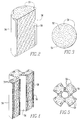
chamber 56 containing a reforming catalyst material comprising a reforming catalyst support configured according to the invention impregnated with catalyst, shown partly cut away along a direction of axial elongation. - FIGURE 2, which best illustrates the invention, is a lateral section view of a monolithic reforming catalyst material comprising a catalyst support arrangement according to an embodiment, showing separate adjacent gas passageways integrally defined within the catalyst support for reducing pressure drop across the catalyst material and for transferring thermal energy from the hot gases to the reformable gases, at least the latter being heated in the presence of a reforming catalyst doped on the catalyst support.
- FIGURE 3 is a top view of the catalyst material of FIGURE 2.
- FIGURE 4 is a lateral section view of a finned reforming catalyst material including a catalyst support arrangement according to the invention, showing a plurality of compact, stackable discs, each disc having separate adjacent passageways integrally defined with each catalyst support disc, for reducing pressure drop across the catalyst material and for transferring thermal energy from the hot gases to the reformable gases, at least the latter being heated in the presence of a reforming catalyst doped on the catalyst support, and
- FIGURE 5 is a top view of the catalyst material of FIGURE 4.
- The term "fuel electrode" as used herein means that electrode in contact with hydrocarbon fuel, the term "air electrode" as used herein means that electrode in contact with air or oxygen. The terms "spent" fuel or "spent" oxidant as used herein refer to partially reacted, low BTU fuel, or partially reacted, depleted oxidant, that is, containing about 5 to 15% oxygen, respectively. The term "spent" does not include the mixture of the spent fuel combusted with spent oxidant, which mixture is described herein as "combusted exhaust" gas.
- Referring to FIGURE 1, an electrochemical apparatus or
generator 10 is shown containing cell bundles 12 and 14, each bundle having a plurality of parallel elongatedelectrochemical fuel cells 16, such as solid oxide electrolyte fuel cells. The fuel cells are located in agenerator chamber 22, and can be arranged with the cells or bundles arranged in a rectangular or circular configuration, etc. - Each
fuel cell 16 has anexterior fuel electrode 18 covering its elongated surface, shown as a stippled section for the sake of clarity, an interior air electrode, and a solid oxide electrolyte between the electrodes. The air electrode and electrolyte are not shown specifically in FIGURE 1, and can be arranged in a manner that is known in the art. The air electrode can be a doped ceramic of the perovskite family, for example, doped LaMnO₃. The electrolyte can by yttria-stabilized zirconia. The fuel electrode can be a zirconia-nickel cermet material. A calcia stabilized zirconia support for the air electrode can optionally be used. - The electrochemical generator apparatus is intended to operate with an interior temperature in the range of about 600°C to about 1200°C. An
outer housing 20 generally surrounds the electrochemical generator apparatus. The housing is typically comprised of a high temperature resistant metal such as Inconel or the like. An inner housing (not shown) can surround a plurality of chambers including thegenerator chamber 22 and acombustion chamber 24. The inner housing, if any, can also comprise a high temperature resistant metal such as Inconel.Thermal insulation 26, such as low density alumina, preferably is disposed within theouter housing 20. - Penetrating the
housing 20 andinsulation 26 are a fresh hydrocarbonfeed fuel inlet 28, where the fresh hydrocarbon feed fuel is shown as F, and anoxidant feed inlet 30, where the oxidant such as air is shown as O. Ports can also be provided for electrical leads and the like (not shown). - The
generator chamber 22 extends between awall 32 and aporous barrier 34. Theporous barrier 34 is designed to allow spent fuel gas to exit, as indicated byarrows 36, from thegenerator chamber 22 to thecombustion chamber 24. The generator chamber operates at a pressure slightly above atmospheric, and thecombustion chamber 24, operates at a slightly lower pressure than the generator chamber. The spentgas 36 combines with spent oxidant, as indicated byarrows 46, forming a hot combusted exhaust gas, as shown as E, which passes through combustedexhaust channel 38. - High temperature, elongated, solid oxide
electrolyte fuel cells 16 extend between thecombustion chamber 24 andwall 32 and are disposed ingenerator chamber 22. Thefuel cells 16 have open ends 40 at thecombustion chamber 24, and closed ends nearwall 32, leading to thegenerator chamber 22. Each individual cell generates approximately one volt at nominal loading, and a plurality of cells are electrically interconnected throughconductive felts 42, typically nickel fiber metal. The cells can be connected in a series-parallel array to obtain a desired relationship of output voltage to current capacity. - By way of example, during operation of the
electrochemical generator apparatus 10, a gaseous oxidant O, such as air, is fed throughoxidant feed inlet 30, and entersoxidant feed conduits 44, for example at a temperature of approximately 500°C to 700°C, and above atmospheric pressure. The oxidant optionally can be heated prior to entering the housing by conventional means, such as a heat exchanger coupled with a blower. The oxidant inconduits 44 is then passed through thecombustion chamber 24, where it is further heated to a temperature of approximately 800°C to 900°C by the combusted exhaust gas E. The oxidant then flows through the length of the oxidant circuit, through theconduits 44 which extend down the interior length of thefuel cells 16, being further heated to approximately 1000°C, by virtue of absorbing most of the heat generated during the electrochemical reaction. A smaller fraction of the heat is absorbed by the fuel. - The oxidant is discharged into the closed end bottom of the
fuel cells 16. The oxidant within the fuel cells reverses direction, and electrochemically reacts at the inner air electrode along the inside active length of the fuel cells, being depleted somewhat in oxygen content as it approaches the opposite open end 40 of thefuel cells 16. - The oxidant is reduced at the air electrode-electrolyte interface, supplying oxygen ions which migrate through the electrolyte to the fuel electrode-electrolyte interface where they are oxidized in the presence of reformed hydrocarbon fuel to produce electrons which flow through an external load circuit to the air electrode, thus generating a flow of electrical current. The electrochemical reactions at the air and fuel electrodes where hydrogen is used as a fuel, for example, are given by the following equations:


- The depleted or spent oxidant is then discharged into the
combustion chamber 24 through the open fuel cell ends 40, and is shown as spent oxidant exit streams 46. The spentoxidant 46 combusts with depleted or spent fuel, part of which passes throughporous barrier 34 as shown byarrow 36, to form combusted exhaust gas, which exits the apparatus, for example, through one or morecombusted exhaust channels 38, finally exiting as the exhaust gas shown as E. The combusted exhaust gas E can be directed to pass in heat transfer communication with the wall of a reformer prior to exiting the apparatus. The combustedexhaust channels 38 can be made of a high temperature resistant metal, such as Inconel. - In the invention, a gaseous hydrocarbon feed fuel F that has not yet been reformed, such as a gaseous hydrocarbon, including hydrocarbons such as methane, ethane, propane and the like, vaporized petroleum fractions such as naphtha, alcohols such as ethyl alcohol and the like, and/or natural gas, can be fed to the electrochemical generator apparatus through fresh feed
fuel inlet channel 28. For example, a mixture of 85% methane, 10% ethane with a balance of propane, butane and nitrogen, can be fed into the electrochemical generator apparatus through fresh hydrocarbon feedfuel inlet channel 28 and reformed in a reformingchamber 56 into combustible compounds less likely to produce carbon formations and soot on acatalyst material 58 within the reformingchamber 56. The term "catalyst material" as used herein refers to a reforming catalyst support material having a reforming catalyst treated, impregnated or doped thereon, and optionally including other promoters or the like. - In the embodiment shown in FIGURE 1, a major portion of the hot, gaseous spent fuel formed along the length of the
fuel cells 16 passes to at least one spentfuel recirculation channel 48. Spentfuel recirculation channel 48 likewise can be made of a high temperature resistant metal such as Inconel. Another portion of the hot spent fuel passes into acombustion chamber 24, as previously shown byarrow 36, to combust with spent oxidant, as previously shown byarrow 46, and to preheat the fresh oxidant feed O. The spentfuel recirculation channel 48 containing spent fuel passes from thegenerator chamber 22 to feed into and combine with the fresh hydrocarbon feed fuel containing feed fuel F at a mixingapparatus 50. - The mixing
apparatus 50 can be any known type in the art, for example, an ejector, jet pump, nozzle, aspirator, mixer-nozzle/mixer-diffuser or the like. This allows recirculation of a portion of the spent fuel fed into spentfuel recirculation channel 48 to mix with the fresh hydrocarbon feed fuel F fed throughinlet 28 at the mixingapparatus 50 to produce a reformable gas fuel mixture, as shown byarrows 54. In addition, the mixer optionally can be designed such that the dynamic energy of the fuel mixture at the entrance to themixer 50, such as a nozzle, is effectively converted to an elevated pressure at an entrance to a reformingchamber 56 by adiffuser 52, the cross-sectional area of which gets larger as it proceeds from its entrance near the nozzle, to the reformingchamber 56. - Prior to passing through the catalytic
hydrocarbon reforming chamber 56, the reformablegas fuel mixture 54 generally contains at least H₂O vapor (steam), and typically also H₂, CO and CO₂, all contributed by the spent fuel that enters themixer apparatus 50 through the spentfuel recirculation channel 48. Preferably, the volume ratio of spent fuel to fresh feed fuel is adjusted by controlling the velocity of the fresh feed fuel input in the mixingapparatus 50 so that approximately two volumes to five volumes of H₂O (steam) and CO₂ are added to each volume of fresh feed fuel. A preferred O:C volume ratio is from about 1.2:1 to 3:1 for a natural gas fueled electrochemical fuel cell generator. The presence of H₂O(g) and/or CO₂ plus a reforming catalyst material allows for the conversion of gaseous hydrocarbons to CO and H₂ and reduces the rate of carbon formation due to hydrocarbon cracking. - The reforming reactions for methane and ethane (natural gas) using water and carbon dioxide, for example, are given by the following equations:


and,

- The reforming reaction is endothermic and best performed at a temperature of about 900°C.
- In the embodiment shown in FIGURE 1, the hydrocarbon reformable
gaseous fuel mixture 54 next passes from the exit of the mixing apparatus through a catalytichydrocarbon reforming chamber 56 containing a hydrocarbon reformingcatalyst material 58 cartridge comprising a self-supporting catalyst support material that is treated with a reforming catalyst and optionally also treated with promoters or the like. The reformable gas mixture is reformed into a relatively low carbonizing fuel, as shown by arrows 64, and exits the reforming chamber into thegenerator chamber 22 through generatorchamber entry ports 66 parallel to thegenerator chamber 22. - The reforming
chamber 56, as shown in FIGURE 1, can contain, for example, a reformingcatalyst material 58 having an elongated, cylindrical, catalyst support configuration that defines elongated flow channels orpassageways 59 extending throughcatalyst material 58 positioned in the reformingchamber 56, elongated in the direction of the reformable gas flow path. The channels can be defined in part by annular openings between concentric tubular sections, axial slots, grooves or channels, and/or otherwise formed as explained more fully hereinafter. The reformingchamber 56 can be made of a high temperature resistant metal such as Inconel and configured to accept the reformingcatalyst material 58 correspondingly configured therein. - The spent
fuel recirculation channel 48 is preferably arranged for thermally conductive contact with the means defining theflow channels 59 of the reformingchamber 56, to allow heat transfer between hot spent gas in therecirculation channel 48 and thereformable gases 54 passing through the reformingchamber 56. This arrangement transfers heat energy from the recirculated spent fuel to provide heat energy needed for the endothermic reforming reaction, which is best performed at approximately 900°C. Additionally, according to the embodiment in FIGURE 1, the recirculated spent fuel continues inrecirculation channel 48 down and around to the mixingnozzle 50 and in contact with the outside of themixer diffuser chamber 52 with a further transfer of heat energy to the reformable fuelgaseous mixture 54 as it approaches the reformingchamber 56. - The combusted
exhaust gas channel 38 can also optionally be arranged for thermal transfer to the reformingchamber 56 to provide additional heat to the reformer in a similar manner. For example, the combustedexhaust gas channel 38 can be arranged to pass through an annular opening between concentric tubular sections of the reforming chamber. - Further, in the embodiment FIGURE 1, the temperature of the spent fuel can be reduced from approximately 1000°C at the entrance to the
recirculation fuel channel 48 to a sufficiently low temperature as it approaches the mixingnozzle 50 that the fresh hydrocarbon feed fuel F does not exceed 400°C. The configuration, thus, can further prevent carbon deposition and soot formation due to hydrocarbon cracking which occurs at temperatures above 400°C. - According to one aspect of the invention, the reforming
chamber 56 generally comprises a walled vessel containing a reformingcatalyst material 58 therein, the reforming catalyst material havingseparate flow channels 59 extending along the flow path of the reformable gas, directed toward the fuel cells, and the flow paths of one or both of the hot spent gas and the combusted exhaust gas directed in close proximity to the reformable gas flow paths. Heat energy passes through the body of the reforming chamber from one of the flow paths to the other. The flow path for at least the reformable gas is lined with the reforming catalyst, and preferably the catalyst is included on the surfaces defining the reformable gas flow path. - A number of alternative specific structures for the reforming
chamber 56 are possible. The reformingchamber 56 can have a circular, oval or rectangular cross section and can be more or less thick. Whereas the body of the reformingchamber 56 is traversed by the adjacentdiscrete passageways 59 defined in the reformingcatalyst material 58, theseparate flow paths 59 of the gases are defined in a manner that brings the gases into thermal transfer relationship in a compact and effective manner. Moreover, theflow paths 59 allow thereformable gas mixture 54 to traverse the reformingchamber 56 without substantial reduction in pressure across the catalyst. - In one embodiment as shown in FIGURE 2 and FIGURE 3, the reforming
chamber 56 can contain a reformingcatalyst material 58 comprising an elongated catalyst support material impregnated with reforming catalyst. The catalyst support is generally cylindrical and defines a plurality offlow passageways 59 for thereformable gas mixture 54, the flow passageways being disposed parallel to and at a radial distance from the central axis of the catalyst support. Preferably, the catalyst support material is made from non-rigid, porous, fibrous, substantially unsintered, alumina that is impregnated with catalytic Ni and MgO. The plurality of radial-groove orslot passageways 59 can be integrally formed within the catalyst support material by known occlusion techniques such as, for example, by selectively compressing the flow path areas. The plurality of radial-groove orslot passageways 59 for thereformable gas mixture 54 are formed to extend radially inwardly from the outer circumference to improve heat transfer and resistance to pressure drop across the catalyst material. - The groove or
slot passageways 59 are closed on the outside by suitable reformingchamber containment walls 56, such as high temperature resistant Inconel or the like, which can guide the hot spent fuel gas in the spent fuelgas recirculation channel 48 downwardly, as shown, or upwardly (not shown), to define either concurrent or countercurrent flow. The groove orslot passageways 59 can also be closed on the outside by a separate high temperature resistant metal walls such as Inconel. It is also possible that the separate passageways could be oriented in another manner or arranged for flows in other relative directions such as concurrent, countercurrent or cross flows in an electrochemical generator that was generally configured differently. It is also possible that thecatalyst material 58 comprise a catalyst support which also defines an axial passage closed by suitable inner reforming chamber containment walls or separate metal walls, the axial passageways being used for spent fuel gas and/or combusted exhaust gas to flow within. The catalyst material, accordingly, includes an additional plurality ofpassageways 59 for thereformable gas mixture 54 disposed parallel to the axial passage and at a radial distance from the inner circumference as is shown in FIGURE 4. - FIGURE 4 and FIGURE 5 show an alternative embodiment in which the reforming
catalyst material 58 comprises a catalyst support impregnated with catalyst which is configured as a tubular and finned arrangement to define inner andouter flow channels 59 extending parallel to the axis of the generally tubular catalyst support material. Moreover, FIGURE 4 shows the reformingmaterial 58 as stackable discs, each disc having thediscrete flow paths 59 defined therein. The discs provide for easier assembly and disassembly of the catalyst material in the reforming chamber. The catalyst material is confined by inner and outer tubular walls, for example, the reformingchamber walls 56, of thermally conductive material, such as Inconel, thereby defining separate passageways for thereformable gas mixture 54. The surfaces at which thereformable gas mixture 54 contacts the reformingcatalyst material 58 in this case is defined by generally rectangular grooves orslots 59 along the direction of reformable gas flow. Other shapes are also possible. Furthermore, the grooves can define irregular shapes, for example defining a scalloped or rippled surface, for providing increased surface area along the flow paths. - Referring again to the embodiment in FIGURE 1, the reforming
chamber 56 is preferably arranged in an axially elongated tube for accepting the reformingcatalyst material 58 therein and to couple the reformable gasmixture fuel inlet 60 and reformedgas fuel outlet 62. At least this passage for thereformable gas mixture 54 contains a reformingcatalyst material 58 including catalyst support and catalyst as generally shown in FIGURES 2 and 4. The reformingchamber containment walls 56, therefore, enclose around the outside of the reformingmaterial 58 and can define part of the walls of the separate flow channels 59 (that is, the outermost channels in FIGURE 2 and both the outermost and innermost channels in FIGURE 4.) - For this purpose, the reforming
catalyst material 58 includes a catalyst support body which is preferably made of a self-supporting material, preferably comprising a self-supporting, porous alumina material which is impregnated with catalytic Ni and possibly MgO, and optionally promoters. The reformingcatalyst material 58 having the configuration according to the invention can comprise conventional rigid, pressed or sintered alumina catalyst support impregnated i.e., distributed throughout the bulk of the catalyst support material, with a reforming catalyst. However, a conventional rigid catalyst support is not preferred. According to the other aspect of the invention as explained more fully hereinafter, it is most preferable for the reformingcatalyst material 58 comprise a non-rigid, porous, fibrous alumina support impregnated at least on the reformable gas mixture contacting surfaces with catalytic material, wherein the catalyst support is flexible and substantially not sintered, and then molded into the required shape to define the separate reformable gas contacting surfaces or flowchannels 59 along the length of the catalyst support. The reforming catalyst typically comprises catalytic Pt and Ni, preferably Ni, and can also comprise metal salts and metal oxides selected from the group of Mg, Ca-Al, Sr-Al, Zr, Y, Ce, Ba and mixtures thereof, preferably Mg and Ca, even more preferably Mg. - Thus, rather than using a packed bed of commercial catalyst pellets contained within a reforming chamber containment walls, and thus substantially occluding the flow path, the reforming
catalyst material 58 configuration havingdiscrete passageways 59 defined along the length of the catalyst support according to the invention includes a catalyst support that integrally exposes the impregnated reforming catalyst along surfaces that contact the reformablefuel gas mixture 54 without substantial pressure drops, while also definingadjacent passageways 59 for appropriate transfer of heat energy. The result is good heat transfer, a low pressure drop, a very compact, easy to assemble and efficient arrangement for thecatalyst material 58 and the reformingchamber 56. The heat transfer can be further improved by partly defining certain of the passageways by reformingchamber containment walls 56 made of high temperature resistant thermally conductive material (that is, metal), such passageways being also partly defined by outer surfaces of thecatalyst material 58 itself. - Thus, the low pressure drop and high heat
flux flow channels 59 defining the reformable gas contacting surfaces directs a substantial portion of thereformable gas mixture 54 flow to be adjacent the hot reformingchamber wall 56 where the preferably-irregular surface receives thermal energy from the reforming chamber partitioning wall and transfers heat energy to the reformable gas mixture by radiation, conduction and convection. Therefore, theflow channels 59 provide superior heat transfer to the reformable gas mixture, while maintaining close contact between the catalytic sites and the reformable gas stream. By using this reforming catalyst material configuration, a significant increase in heat transfer area per reformer volume can result. Therefore, this catalyst configuration is particularly adaptable to many compact geometries, which would not be practical with commercial catalyst pellets. - The
flow channels 59 additionally allow for a substantially unobstructed flow path of thereformable gas mixture 54 through the reformingchamber 56 and substantially reduce pressure drop in the reforming chamber. This is particularly advantageous in a fuel cell generator apparatus where pumping pressure available to drive thereformable gas mixture 54 through a reformingcatalyst material 58 is limited. Moreover, the use of elongated pieces of reforming catalyst material configured withintegral flow channels 59 defined in the catalyst support along the continuum thereof can also provide significant improvement in the catalyst installation and removal process over that required for loose catalyst pellets in a reforming chamber. - It will be appreciated that other particular configurations having such integrally formed separate flow paths are also possible. Additionally, the invention can be applied to other specific flow configurations for electrochemical generators having internal catalytic hydrocarbon reforming chambers, for example, as taught in U.S. Patent Specification Nos. 5,143,800 (George et al.); and, 5,169,730 (Reichner), which are hereby incorporated.
- According to the other aspect of the invention, the reforming
catalyst material 58 comprises a porous, non-rigid and, thus, flexible catalyst support material which substantially reduces mechanical or dimensional breakdown of the reformingcatalyst material 58 that is believed to result from slow deposition or buildup of carbon on the reforming catalyst material upon prolonged reforming operations. - It is known that the long term operation of a hydrocarbon fueled electrochemical generator, such as a high temperature, solid oxide electrolyte fuel cell generator containing an internal reforming chamber containing commercial reforming catalyst pellets cause problems. Commercial rigid, porous, sintered alumina catalyst supported, nickel-based reforming catalyst pellets are prone to mechanical degradation, pulverization and dusting, due to slow deposition of carbon. Carbon deposition leads to a pressure buildup across the reformer bed and, consequently, degradation of the generator's electrical output. Structural and chemical analysis of a disintegrated and pulverized catalyst in a electrochemical generator has shown that the mechanical breakdown is due to carbon formation in the catalyst, especially filamentary carbon formation.
- The porous, non-rigid, fibrous, substantially unsintered, reforming
catalyst material 58 according to the invention is characterized by an alumina catalyst support that is not rigidly sintered or pressed to rigidity and, therefore, is not characterized by extensive rigid inter-particle and interfiber bonding. Thus, the reforming catalyst support does not contain rigid sintered contacts between granular or fibrous supports. In the absence of these rigid contacts, the catalyst support is flexible and compressible and remains substantially resistant to dimensional and mechanical degradation, pulverization, dusting and fracturing during carbon formation and further during subsequent removal of carbon from the support by oxidation. The non-rigid alumina support is made from alumina fibers interwoven together that make it flexibly compressible and substantially resistant to internal stresses developed in the catalyst material due to carbon deposition. The non-rigid, porous, alumina support is preferably treated or impregnated with catalytic Ni to reform the hydrocarbons and also MgO to improve H₂O adsorption. The catalytic doping materials, for example Pt and Ni, preferably Ni, and modifiers, for example metal salts and metal oxides selected from the group of Mg, Ca-Al, Sr-Al, Zr, Y, Ce, Ba and mixtures thereof, preferably Mg and Ca, even more preferably Mg, and the method of impregnation on the catalyst support are taught in U.S. Patent Specification No. 4,898,792 (Singh et al.). - The flexible or compressible catalyst support material according to the invention remains flexible during reforming operations and, therefore, upon the slow deposition of carbon on the surfaces thereof, it is not subjected internal stresses that accompany conventional materials. It therefore remains substantially intact over prolonged operations. The catalyst supports remains flexible by being made from fibers and not being substantially sintered.
- The invention will be further clarified by a consideration of the following example, which is intended to be purely exemplary of the use of the invention.
- A reforming catalyst material according to the invention was prepared by impregnating a non-rigid, porous, substantially unsintered, alumina support material (fibrous alumina (Al₂O₃) based insulation material (ZAL-15)) with Ni and MgO by the method of impregnation disclosed in U.S. Patent Specification No. 4,898,792 (Singh et al.). The reforming catalyst material was then positioned in a reforming chamber of a high temperature, solid oxide electrolyte generator apparatus, such as shown in FIGURE 1, in the presence of a CH₄-H₂O gas mixture (steam to carbon ratio of 1:1) at 500°C for about 65 hours. A commercial prior art rigid, sintered alumina catalyst support impregnated with Ni and MgO in the form of pellets was also prepared and tested as described above.
- The conventional catalyst support impregnated with catalyst showed severe mechanical disintegration, pulverization, fracturing and dusting of the catalyst support due to carbon deposition, whereas the non-rigid reforming catalyst support treated with catalyst according to the invention remained structurally and dimensionally stable without any substantial dusting or pulverization. The reforming catalyst material according to this aspect of the invention can be configured as described above according to the other aspect of the invention. The reforming catalyst material can also be positioned in a reforming chamber as a continuum or in conjunction with a catalyst pellet bed.
- The invention having been disclosed in connection with the foregoing variations and examples, additional variations will now be apparent to persons skilled in the art. The invention is not intended to be limited to the variations specifically mentioned, and accordingly reference should be made to the appended claims rather than the foregoing discussion of preferred examples, to assess the scope and spirit of the invention in which exclusive rights are claimed.
Claims (18)
- A hydrocarbon reforming catalyst material configuration, characterized by having a porous reforming catalyst support impregnated with catalyst, said catalyst support elongated in a direction of flow of a reformable hydrocarbon gas, wherein a reformable gas contacting surface of the catalyst support defines at least one discrete passageway extending along the length of the catalyst support forming a reformable gas flow channel, said at least one discrete passageway is in heat communication with means for heating the reformable hydrocarbon gas in said at least one discrete passageway.
- The hydrocarbon reforming catalyst material configuration of claim 1, characterized in that the reformable hydrocarbon gas contacting surface comprises a plurality of discrete passageways extending along the length of the catalyst support forming a plurality of gas flow channels, at least one of the gas flow channels carrying reformable hydrocarbon gas.
- The hydrocarbon reforming catalyst material configuration of claim 2, characterized in that the gas flow channels are formed at least partly by integral slots extending inwardly into the catalyst support and elongated in the direction of gas flow.
- The hydrocarbon reforming catalyst material configuration of claim 3, further characterized in that at least one confining wall disposed around the catalyst support, the confining wall partly closing the integral slot.
- The hydrocarbon reforming catalyst material configuration of claim 4, characterized in that the confining wall is made of a high temperature resistant, thermally conductive metal or alloy.
- The hydrocarbon reforming catalyst material configuration of claim 2, characterized in that the catalyst support is generally cylindrical and elongated in the direction of gas flow.
- The hydrocarbon reforming catalyst material configuration of claim 2, characterized in that the catalyst support is generally rectangular and elongated in the direction of gas flow.
- The hydrocarbon reforming catalyst material configuration of claim 2, characterized in that the catalyst support comprises a plurality of discs, stackable one upon each other.
- The hydrocarbon reforming catalyst material configuration of claim 2, characterized in that the catalyst support has at least one central passageway and at least one integral slot extending inwardly into the catalyst support body, the central passageway and slot being elongated in the direction of gas flow.
- The hydrocarbon reforming catalyst material configuration of claim 2, characterized in that the reforming catalyst material comprises a porous, alumina catalyst support impregnated with a reforming catalyst selected from the group of metals consisting of Ni and Pt.
- The hydrocarbon reforming catalyst material configuration of claim 10, characterized in that the reforming catalyst further comprises metals or metal oxides selected from the group consisting of Mg, Ca-Al, Sr-Al, Ce and Ba.
- The hydrocarbon reforming catalyst material configuration of claim 2, characterized in that the reforming catalyst impregnated on the catalyst support comprises Ni and MgO.
- The hydrocarbon reforming catalyst material configuration of claim 2, characterized in that the reforming catalyst material support comprises a non-rigid, porous, fibrous alumina catalyst support, wherein the fibers are compressible and substantially unsintered and are impregnated with Ni and MgO.
- An electrochemical generator apparatus characterized by:
an elongated generator chamber containing at least one cell bundle, the bundle containing a plurality of parallel, elongated electrochemical cells, each cell having an exterior fuel electrode, an interior air electrode, and a solid oxide electrolyte therebetween;
a fresh gaseous feed fuel inlet to the generator chamber;
a gaseous feed oxidant inlet to the generator chamber;
at least one gaseous spent fuel exit from the generator chamber;
a combustion chamber;
at least one gaseous combusted exhaust exit from the combustion chamber; and,
a reforming chamber containing a hydrocarbon reforming catalyst material comprising a catalyst support impregnated with a reforming catalyst,
wherein a spent fuel exit channel passes from the generator chamber to combine with a fresh hydrocarbon feed fuel inlet at a mixing chamber and a reformable hydrocarbon gas mixture passes from the mixing chamber to the reforming chamber wherein the reformable hydrocarbon gas mixture is substantially reformed and passes from the reforming chamber into the generator chamber, and,
wherein the a reformable gas contacting surface of the reforming catalyst support comprises at least one discrete passageway formed at least partly integrally in the reforming catalyst support and extending along the length of the reforming catalyst support in the direction of reformable hydrocarbon gas flow forming a reformable gas flow channel, said at least one discrete passageway being in heat communication with means for heating the reformable hydrocarbon gas in said at least one discrete passageway. - The electrochemical generator apparatus of claim 14, characterized in that the reformable gas contacting surface comprises a plurality of discrete passageways disposed adjacent one another in the catalyst support, and further comprising means for directing the reformable gas through the discrete passageways.
- The electrochemical generator apparatus of claim 14, characterized in that the means for heating said reformable hydrocarbon gas comprises said spent gas exit or combusted exhaust gas exit is directed in heat communication with a wall of the reforming chamber, wherein the wall of the reforming chamber is disposed around the catalyst support, partly closing the at least one discrete passageway.
- The electrochemical generator apparatus of claim 15, characterized in that the reforming catalyst material comprises a catalyst support impregnated with catalyst in which the gas flow channels are formed at least partly by integral slots extending inwardly into the body and elongated in the direction of gas flow.
- The electrochemical generator apparatus of claim 15, characterized in that the reforming catalyst material comprises a catalyst support having at least one central passage and at least one integral slot extending inwardly into the body, the central passage and the slot being elongated in the direction of gas flow, and further comprising at least one confining wall disposed around the body, the confining wall partly closing the integral slot.
Applications Claiming Priority (2)
| Application Number | Priority Date | Filing Date | Title |
|---|---|---|---|
| US19871194A | 1994-02-18 | 1994-02-18 | |
| US198711 | 2002-07-16 |
Publications (2)
| Publication Number | Publication Date |
|---|---|
| EP0677327A1 true EP0677327A1 (en) | 1995-10-18 |
| EP0677327B1 EP0677327B1 (en) | 1998-12-23 |
Family
ID=22734480
Family Applications (1)
| Application Number | Title | Priority Date | Filing Date |
|---|---|---|---|
| EP95300927A Expired - Lifetime EP0677327B1 (en) | 1994-02-18 | 1995-02-14 | Hydrocarbon reforming catalyst material and configuration of the same |
Country Status (7)
| Country | Link |
|---|---|
| US (1) | US5527631A (en) |
| EP (1) | EP0677327B1 (en) |
| JP (1) | JPH0822835A (en) |
| KR (1) | KR950031230A (en) |
| CA (1) | CA2142781A1 (en) |
| DE (1) | DE69506767T2 (en) |
| TW (1) | TW299345B (en) |
Cited By (5)
| Publication number | Priority date | Publication date | Assignee | Title |
|---|---|---|---|---|
| WO2001053196A1 (en) * | 2000-01-21 | 2001-07-26 | Conoco Inc. | Thermal shock resistant catalysts for synthesis gas production |
| WO2002038495A1 (en) * | 2000-11-12 | 2002-05-16 | Klaus Rennebeck | Method and device for obtaining hydrogen by means of a catalytic micro-hollow fibre reformer |
| EP1949477A2 (en) * | 2005-11-16 | 2008-07-30 | Fuelcell Energy, Inc. | Improved reforming catalyst and method and apparatus for making and loading same |
| US9093682B2 (en) | 2013-08-26 | 2015-07-28 | 19 Space Energy, LLC | Reforming chamber with multiple electrodes to generate hydrogen |
| WO2018049212A1 (en) * | 2016-09-09 | 2018-03-15 | Fuelcell Energy, Inc. | Molten carbonate fuel cell stack having direct and indirect internal reformers |
Families Citing this family (109)
| Publication number | Priority date | Publication date | Assignee | Title |
|---|---|---|---|---|
| DE4438555C1 (en) * | 1994-10-28 | 1996-03-07 | Mtu Friedrichshafen Gmbh | Fuel cell arrangement with reforming device |
| DK175723B1 (en) * | 1995-03-20 | 2005-02-07 | Topsoe Haldor As | Process for producing electrical energy in a high temperature fuel cell |
| WO1999010945A1 (en) * | 1997-08-26 | 1999-03-04 | Shell Internationale Research Maatschappij B.V. | Producing electrical energy from natural gas using a solid oxide fuel cell |
| US6641625B1 (en) | 1999-05-03 | 2003-11-04 | Nuvera Fuel Cells, Inc. | Integrated hydrocarbon reforming system and controls |
| US6440594B1 (en) * | 1999-06-17 | 2002-08-27 | California Institute Of Technology | Aerosol feed direct methanol fuel cell |
| US6221522B1 (en) * | 1999-09-10 | 2001-04-24 | Siemens Westinghouse Power Corporation | Open end protection for solid oxide fuel cells |
| US6440596B1 (en) | 1999-10-20 | 2002-08-27 | Technology Management, Inc. | Solid-oxide fuel cell hot assembly |
| US6489050B1 (en) | 1999-11-01 | 2002-12-03 | Technology Management, Inc. | Apparatus and method for cooling high-temperature fuel cell stacks |
| DE10030775C1 (en) * | 2000-06-23 | 2001-12-20 | Buderus Heiztechnik Gmbh | Fluid dosing method for gas generation device for fuel cell system uses central 3-way mixing valve for pulsed dosing of hydrocarbon and water in alternation |
| US6946209B1 (en) | 2000-09-25 | 2005-09-20 | Siemens Westinghouse Power Corporation | Desulfurization for fuel cell systems using sulfur separating membranes |
| US20020122969A1 (en) * | 2000-12-15 | 2002-09-05 | Manfred Herrmann | Pressure driven hermetically sealed pump for fuel cell system |
| US7182924B2 (en) * | 2001-03-13 | 2007-02-27 | Corning Incorporated | Substrate packing for monolith reactors |
| US6855272B2 (en) * | 2001-07-18 | 2005-02-15 | Kellogg Brown & Root, Inc. | Low pressure drop reforming exchanger |
| US7067208B2 (en) * | 2002-02-20 | 2006-06-27 | Ion America Corporation | Load matched power generation system including a solid oxide fuel cell and a heat pump and an optional turbine |
| AU2003294103A1 (en) * | 2002-08-07 | 2004-03-19 | Battelle Memorial Institute | Passive vapor exchange systems and techniques for fuel reforming and prevention of carbon fouling |
| US20040043900A1 (en) * | 2002-08-12 | 2004-03-04 | Combs Glenn A. | Heterogeneous gaseous chemical reactor catalyst |
| US6821663B2 (en) * | 2002-10-23 | 2004-11-23 | Ion America Corporation | Solid oxide regenerative fuel cell |
| US20040229108A1 (en) * | 2002-11-08 | 2004-11-18 | Valdez Thomas I. | Anode structure for direct methanol fuel cell |
| US7282291B2 (en) * | 2002-11-25 | 2007-10-16 | California Institute Of Technology | Water free proton conducting membranes based on poly-4-vinylpyridinebisulfate for fuel cells |
| US6924053B2 (en) * | 2003-03-24 | 2005-08-02 | Ion America Corporation | Solid oxide regenerative fuel cell with selective anode tail gas circulation |
| US7045238B2 (en) * | 2003-03-24 | 2006-05-16 | Ion America Corporation | SORFC power and oxygen generation method and system |
| US7878280B2 (en) * | 2003-04-09 | 2011-02-01 | Bloom Energy Corporation | Low pressure hydrogen fueled vehicle and method of operating same |
| US7364810B2 (en) | 2003-09-03 | 2008-04-29 | Bloom Energy Corporation | Combined energy storage and fuel generation with reversible fuel cells |
| US7575822B2 (en) | 2003-04-09 | 2009-08-18 | Bloom Energy Corporation | Method of optimizing operating efficiency of fuel cells |
| US7482078B2 (en) * | 2003-04-09 | 2009-01-27 | Bloom Energy Corporation | Co-production of hydrogen and electricity in a high temperature electrochemical system |
| US7150927B2 (en) * | 2003-09-10 | 2006-12-19 | Bloom Energy Corporation | SORFC system with non-noble metal electrode compositions |
| JP4986378B2 (en) * | 2003-11-26 | 2012-07-25 | 京セラ株式会社 | Fuel cell assembly |
| US7569193B2 (en) | 2003-12-19 | 2009-08-04 | Applied Materials, Inc. | Apparatus and method for controlled combustion of gaseous pollutants |
| US7422810B2 (en) * | 2004-01-22 | 2008-09-09 | Bloom Energy Corporation | High temperature fuel cell system and method of operating same |
| US7364812B2 (en) * | 2004-03-19 | 2008-04-29 | Pittsburgh Electric Engines, Inc. | Multi-function solid oxide fuel cell bundle and method of making the same |
| KR100599668B1 (en) * | 2004-08-19 | 2006-07-12 | 한국과학기술연구원 | Catalyst stack for partial oxidation reforming of fuel, apparatus for fuel reforming using the catalyst and method for fuel reforming using the catalyst |
| US20060042565A1 (en) * | 2004-08-26 | 2006-03-02 | Eaton Corporation | Integrated fuel injection system for on-board fuel reformer |
| US7736599B2 (en) * | 2004-11-12 | 2010-06-15 | Applied Materials, Inc. | Reactor design to reduce particle deposition during process abatement |
| US7476616B2 (en) * | 2004-12-13 | 2009-01-13 | Fsi International, Inc. | Reagent activator for electroless plating |
| WO2006068319A2 (en) * | 2004-12-22 | 2006-06-29 | Honda Motor Co., Ltd. | Fuel cell system |
| US20060147771A1 (en) * | 2005-01-04 | 2006-07-06 | Ion America Corporation | Fuel cell system with independent reformer temperature control |
| US7514166B2 (en) * | 2005-04-01 | 2009-04-07 | Bloom Energy Corporation | Reduction of SOFC anodes to extend stack lifetime |
| US7524572B2 (en) * | 2005-04-07 | 2009-04-28 | Bloom Energy Corporation | Fuel cell system with thermally integrated combustor and corrugated foil reformer |
| US20060251934A1 (en) * | 2005-05-09 | 2006-11-09 | Ion America Corporation | High temperature fuel cell system with integrated heat exchanger network |
| US8691462B2 (en) | 2005-05-09 | 2014-04-08 | Modine Manufacturing Company | High temperature fuel cell system with integrated heat exchanger network |
| US7858256B2 (en) * | 2005-05-09 | 2010-12-28 | Bloom Energy Corporation | High temperature fuel cell system with integrated heat exchanger network |
| US7700210B2 (en) | 2005-05-10 | 2010-04-20 | Bloom Energy Corporation | Increasing thermal dissipation of fuel cell stacks under partial electrical load |
| JP2008546525A (en) * | 2005-06-13 | 2008-12-25 | アプライド マテリアルズ インコーポレイテッド | Method and apparatus for detoxifying treatment |
| US7520916B2 (en) * | 2005-07-25 | 2009-04-21 | Bloom Energy Corporation | Partial pressure swing adsorption system for providing hydrogen to a vehicle fuel cell |
| US20070017368A1 (en) * | 2005-07-25 | 2007-01-25 | Ion America Corporation | Gas separation method and apparatus using partial pressure swing adsorption |
| JP5542332B2 (en) | 2005-07-25 | 2014-07-09 | ブルーム エナジー コーポレーション | Fuel cell system that partially recycles anode exhaust |
| DK1908144T3 (en) * | 2005-07-25 | 2012-08-13 | Bloom Energy Corp | FUEL CELL SYSTEM WITH ELECTROCHEMICAL ANODE EXHAUST GAS RECYCLING |
| US7591880B2 (en) * | 2005-07-25 | 2009-09-22 | Bloom Energy Corporation | Fuel cell anode exhaust fuel recovery by adsorption |
| WO2007053626A2 (en) * | 2005-10-31 | 2007-05-10 | Applied Materials, Inc. | Process abatement reactor |
| US7659022B2 (en) | 2006-08-14 | 2010-02-09 | Modine Manufacturing Company | Integrated solid oxide fuel cell and fuel processor |
| WO2007087305A2 (en) * | 2006-01-23 | 2007-08-02 | Bloom Energy Corporation | Integrated solid oxide fuel cell and fuel processor |
| US9190693B2 (en) | 2006-01-23 | 2015-11-17 | Bloom Energy Corporation | Modular fuel cell system |
| WO2007095150A2 (en) * | 2006-02-11 | 2007-08-23 | Applied Materials, Inc. | Methods and apparatus for pfc abatement using a cdo chamber |
| US7704617B2 (en) * | 2006-04-03 | 2010-04-27 | Bloom Energy Corporation | Hybrid reformer for fuel flexibility |
| US8822094B2 (en) * | 2006-04-03 | 2014-09-02 | Bloom Energy Corporation | Fuel cell system operated on liquid fuels |
| JP5154026B2 (en) * | 2006-04-14 | 2013-02-27 | 本田技研工業株式会社 | Fuel cell system |
| JP5021229B2 (en) * | 2006-04-14 | 2012-09-05 | 本田技研工業株式会社 | Fuel cell system |
| JP5021237B2 (en) * | 2006-05-18 | 2012-09-05 | 本田技研工業株式会社 | Fuel cell system |
| JP5021238B2 (en) * | 2006-05-18 | 2012-09-05 | 本田技研工業株式会社 | Fuel cell system |
| JP5021236B2 (en) * | 2006-05-18 | 2012-09-05 | 本田技研工業株式会社 | Fuel cell system |
| US8241801B2 (en) | 2006-08-14 | 2012-08-14 | Modine Manufacturing Company | Integrated solid oxide fuel cell and fuel processor |
| WO2008030394A2 (en) * | 2006-09-06 | 2008-03-13 | Bloom Energy Corporation | Flexible fuel cell system configuration to handle multiple fuels |
| US7846600B2 (en) * | 2006-09-21 | 2010-12-07 | Bloom Energy Corporation | Adaptive purge control to prevent electrode redox cycles in fuel cell systems |
| US7968245B2 (en) * | 2006-09-25 | 2011-06-28 | Bloom Energy Corporation | High utilization stack |
| WO2008048445A2 (en) | 2006-10-18 | 2008-04-24 | Bloom Energy Corporation | Anode with remarkable stability under conditions of extreme fuel starvation |
| US10615444B2 (en) | 2006-10-18 | 2020-04-07 | Bloom Energy Corporation | Anode with high redox stability |
| WO2008051368A2 (en) * | 2006-10-23 | 2008-05-02 | Bloom Energy Corporation | Dual function heat exchanger for start-up humidification and facility heating in sofc system |
| US7393603B1 (en) * | 2006-12-20 | 2008-07-01 | Bloom Energy Corporation | Methods for fuel cell system optimization |
| US20090214905A1 (en) * | 2007-01-08 | 2009-08-27 | California Institute Of Technology | Direct methanol fuel cell operable with neat methanol |
| US7883803B2 (en) * | 2007-03-30 | 2011-02-08 | Bloom Energy Corporation | SOFC system producing reduced atmospheric carbon dioxide using a molten carbonated carbon dioxide pump |
| US7833668B2 (en) * | 2007-03-30 | 2010-11-16 | Bloom Energy Corporation | Fuel cell system with greater than 95% fuel utilization |
| WO2008127601A1 (en) | 2007-04-13 | 2008-10-23 | Bloom Energy Corporation | Heterogeneous ceramic composite sofc electrolyte |
| US20080254336A1 (en) * | 2007-04-13 | 2008-10-16 | Bloom Energy Corporation | Composite anode showing low performance loss with time |
| US7846599B2 (en) | 2007-06-04 | 2010-12-07 | Bloom Energy Corporation | Method for high temperature fuel cell system start up and shutdown |
| US8920997B2 (en) | 2007-07-26 | 2014-12-30 | Bloom Energy Corporation | Hybrid fuel heat exchanger—pre-reformer in SOFC systems |
| US8852820B2 (en) | 2007-08-15 | 2014-10-07 | Bloom Energy Corporation | Fuel cell stack module shell with integrated heat exchanger |
| US8067129B2 (en) | 2007-11-13 | 2011-11-29 | Bloom Energy Corporation | Electrolyte supported cell designed for longer life and higher power |
| US9246184B1 (en) | 2007-11-13 | 2016-01-26 | Bloom Energy Corporation | Electrolyte supported cell designed for longer life and higher power |
| WO2009105191A2 (en) | 2008-02-19 | 2009-08-27 | Bloom Energy Corporation | Fuel cell system containing anode tail gas oxidizer and hybrid heat exchanger/reformer |
| JP5396718B2 (en) * | 2008-02-20 | 2014-01-22 | カシオ計算機株式会社 | POWER GENERATION DEVICE, ITS CONTROL DEVICE, OPERATION METHOD, AND ELECTRONIC DEVICE |
| EP2140933A1 (en) | 2008-07-02 | 2010-01-06 | Werner Soyez | Structured catalyst hold for pipe reactors |
| US8968958B2 (en) * | 2008-07-08 | 2015-03-03 | Bloom Energy Corporation | Voltage lead jumper connected fuel cell columns |
| US9287571B2 (en) * | 2008-07-23 | 2016-03-15 | Bloom Energy Corporation | Operation of fuel cell systems with reduced carbon formation and anode leading edge damage |
| WO2010117990A2 (en) * | 2009-04-09 | 2010-10-14 | University Of Miami | Self sustained electrochemical promotion catalysts |
| US8617763B2 (en) * | 2009-08-12 | 2013-12-31 | Bloom Energy Corporation | Internal reforming anode for solid oxide fuel cells |
| US8445156B2 (en) * | 2009-09-02 | 2013-05-21 | Bloom Energy Corporation | Multi-stream heat exchanger for a fuel cell system |
| WO2011094098A2 (en) * | 2010-01-26 | 2011-08-04 | Bloom Energy Corporation | Phase stable doped zirconia electrolyte compositions with low degradation |
| US8440362B2 (en) | 2010-09-24 | 2013-05-14 | Bloom Energy Corporation | Fuel cell mechanical components |
| US8877399B2 (en) | 2011-01-06 | 2014-11-04 | Bloom Energy Corporation | SOFC hot box components |
| JP6041162B2 (en) * | 2012-08-01 | 2016-12-07 | 国立大学法人九州大学 | Paper-like catalyst for reforming hydrocarbons, paper-like catalyst array, and solid oxide fuel cell having paper-like catalyst or paper-like catalyst array |
| JP6339582B2 (en) | 2012-11-20 | 2018-06-06 | ブルーム エナジー コーポレーション | Doped scandia stabilized zirconia electrolyte composition |
| US9755263B2 (en) | 2013-03-15 | 2017-09-05 | Bloom Energy Corporation | Fuel cell mechanical components |
| WO2015061274A1 (en) | 2013-10-23 | 2015-04-30 | Bloom Energy Corporation | Pre-reformer for selective reformation of higher hydrocarbons |
| MX352227B (en) | 2013-11-06 | 2017-11-15 | WATT Fuel Cell Corp | Liquid fuel cpox reformers and methods of cpox reforming. |
| JP6253795B2 (en) | 2013-11-06 | 2017-12-27 | ワット・フューエル・セル・コーポレイションWatt Fuel Cell Corp. | Gaseous fuel CPOX reformer and CPOX reforming method |
| JP6285563B2 (en) | 2013-11-06 | 2018-02-28 | ワット・フューエル・セル・コーポレイションWatt Fuel Cell Corp. | Reformer with perovskite as structural component |
| CA2929886C (en) | 2013-11-06 | 2019-03-05 | WATT Fuel Cell Corp | Integrated gaseous fuel cpox reformer and fuel cell systems, and methods of producing electricity |
| US10106406B2 (en) | 2013-11-06 | 2018-10-23 | Watt Fuel Cell Corp. | Chemical reactor with manifold for management of a flow of gaseous reaction medium thereto |
| JP6549600B2 (en) | 2013-11-06 | 2019-07-24 | ワット・フューエル・セル・コーポレイションWatt Fuel Cell Corp. | Liquid fuel CPOX reformer and fuel cell integrated system and method of generating electricity |
| WO2015123304A1 (en) | 2014-02-12 | 2015-08-20 | Bloom Energy Corporation | Structure and method for fuel cell system where multiple fuel cells and power electronics feed loads in parallel allowing for integrated electrochemical impedance spectroscopy ("eis") |
| US10096840B1 (en) | 2014-12-15 | 2018-10-09 | Bloom Energy Corporation | High temperature air purge of solid oxide fuel cell anode electrodes |
| CA2978250C (en) * | 2015-03-05 | 2023-09-26 | Watt Fuel Cell Corp. | Afterburners including methods of making and operating |
| US10651496B2 (en) | 2015-03-06 | 2020-05-12 | Bloom Energy Corporation | Modular pad for a fuel cell system |
| WO2016154198A1 (en) | 2015-03-24 | 2016-09-29 | Bloom Energy Corporation | Perimeter electrolyte reinforcement layer composition for solid oxide fuel cell electrolytes |
| US10361442B2 (en) | 2016-11-08 | 2019-07-23 | Bloom Energy Corporation | SOFC system and method which maintain a reducing anode environment |
| KR102331593B1 (en) * | 2017-03-02 | 2021-11-26 | 로드리고 코키스 산체스-꼰샤 | Hydrodynamic systems for optimizing the performance of catalytic alloys and improving microbial contaminant removal properties of hydrocarbons |
| US10680251B2 (en) | 2017-08-28 | 2020-06-09 | Bloom Energy Corporation | SOFC including redox-tolerant anode electrode and system including the same |
| US11398634B2 (en) | 2018-03-27 | 2022-07-26 | Bloom Energy Corporation | Solid oxide fuel cell system and method of operating the same using peak shaving gas |
| DE102020202875A1 (en) | 2020-03-06 | 2021-09-09 | Robert Bosch Gesellschaft mit beschränkter Haftung | Fuel cell device |
Citations (12)
| Publication number | Priority date | Publication date | Assignee | Title |
|---|---|---|---|---|
| US4233187A (en) * | 1979-03-26 | 1980-11-11 | United Catalysts Inc. | Catalyst and process for steam-reforming of hydrocarbons |
| EP0025308A1 (en) * | 1979-09-06 | 1981-03-18 | Imperial Chemical Industries Plc | A process and apparatus for catalytically reacting steam with a hydrocarbon in endothermic conditions |
| EP0045126A1 (en) * | 1980-06-25 | 1982-02-03 | Imperial Chemical Industries Plc | Catalytic process for producing hydrogen |
| US4407785A (en) * | 1972-11-28 | 1983-10-04 | Engelhard Corporation | Method of conducting catalytically promoted gas-phase reactions |
| JPS61267272A (en) * | 1985-05-22 | 1986-11-26 | Hitachi Ltd | Molten carbonate type fuel cell |
| JPS6280971A (en) * | 1985-10-02 | 1987-04-14 | Hitachi Ltd | Internal reform catalyst material for fuel cell and its manufacture |
| EP0226306A1 (en) * | 1985-11-13 | 1987-06-24 | Imperial Chemical Industries Plc | Self-supporting ceramic structures |
| EP0240796A2 (en) * | 1986-04-08 | 1987-10-14 | Kernforschungszentrum Karlsruhe Gmbh | Catalyst support and process for its preparation |
| EP0376436A1 (en) * | 1988-12-07 | 1990-07-04 | Westinghouse Electric Corporation | Electrochemical generator apparatus containing modified high temperature insulation |
| JPH03109202A (en) * | 1989-09-22 | 1991-05-09 | Ngk Insulators Ltd | Fuel reformer for fuel cell system |
| EP0443241A1 (en) * | 1989-12-28 | 1991-08-28 | Westinghouse Electric Corporation | Electrochemical cell apparatus having axially distributed entries supplying a fuel-spent fuel mixture transverse to the cell lengths |
| EP0468698A1 (en) * | 1990-07-25 | 1992-01-29 | Westinghouse Electric Corporation | Electrochemical cell apparatus having an exterior fuel mixer nozzle |
Family Cites Families (11)
| Publication number | Priority date | Publication date | Assignee | Title |
|---|---|---|---|---|
| US2408164A (en) * | 1942-04-25 | 1946-09-24 | Phillips Petroleum Co | Catalyst preparation |
| US4328130A (en) * | 1980-10-22 | 1982-05-04 | Chevron Research Company | Shaped channeled catalyst |
| US4395468A (en) * | 1980-12-22 | 1983-07-26 | Westinghouse Electric Corp. | Fuel cell generator |
| US4490444A (en) * | 1980-12-22 | 1984-12-25 | Westinghouse Electric Corp. | High temperature solid electrolyte fuel cell configurations and interconnections |
| US4729931A (en) * | 1986-11-03 | 1988-03-08 | Westinghouse Electric Corp. | Reforming of fuel inside fuel cell generator |
| US4751152A (en) * | 1987-04-06 | 1988-06-14 | Westinghouse Electric Corp. | High bulk self-supporting electrode with integral gas feed conduit for solid oxide fuel cells |
| US4885078A (en) * | 1988-12-07 | 1989-12-05 | Westinghouse Electric Corp. | Devices capable of removing silicon and aluminum from gaseous atmospheres |
| US5143800A (en) * | 1990-07-25 | 1992-09-01 | Westinghouse Electric Corp. | Electrochemical cell apparatus having combusted exhaust gas heat exchange and valving to control the reformable feed fuel composition |
| US5047299A (en) * | 1990-07-25 | 1991-09-10 | Westinghouse Electric Corp. | Electrochemical cell apparatus having an integrated reformer-mixer nozzle-mixer diffuser |
| US5082751A (en) * | 1990-10-18 | 1992-01-21 | Westinghouse Electric Corp. | Internal natural gas reformer-dividers for a solid oxide fuel cell generator configuration |
| US5250489A (en) * | 1990-11-26 | 1993-10-05 | Catalytica, Inc. | Catalyst structure having integral heat exchange |
-
1995
- 1995-02-08 TW TW084101050A patent/TW299345B/zh active
- 1995-02-14 DE DE69506767T patent/DE69506767T2/en not_active Expired - Fee Related
- 1995-02-14 EP EP95300927A patent/EP0677327B1/en not_active Expired - Lifetime
- 1995-02-17 KR KR1019950002986A patent/KR950031230A/en not_active Application Discontinuation
- 1995-02-17 CA CA002142781A patent/CA2142781A1/en not_active Abandoned
- 1995-02-20 JP JP7056675A patent/JPH0822835A/en not_active Withdrawn
- 1995-10-04 US US08/539,814 patent/US5527631A/en not_active Expired - Lifetime
Patent Citations (14)
| Publication number | Priority date | Publication date | Assignee | Title |
|---|---|---|---|---|
| US4407785A (en) * | 1972-11-28 | 1983-10-04 | Engelhard Corporation | Method of conducting catalytically promoted gas-phase reactions |
| US4233187A (en) * | 1979-03-26 | 1980-11-11 | United Catalysts Inc. | Catalyst and process for steam-reforming of hydrocarbons |
| US4337178A (en) * | 1979-03-26 | 1982-06-29 | United Catalysts Inc. | Catalyst for steam reforming of hydrocarbons |
| EP0025308A1 (en) * | 1979-09-06 | 1981-03-18 | Imperial Chemical Industries Plc | A process and apparatus for catalytically reacting steam with a hydrocarbon in endothermic conditions |
| EP0045126A1 (en) * | 1980-06-25 | 1982-02-03 | Imperial Chemical Industries Plc | Catalytic process for producing hydrogen |
| JPS61267272A (en) * | 1985-05-22 | 1986-11-26 | Hitachi Ltd | Molten carbonate type fuel cell |
| JPS6280971A (en) * | 1985-10-02 | 1987-04-14 | Hitachi Ltd | Internal reform catalyst material for fuel cell and its manufacture |
| EP0226306A1 (en) * | 1985-11-13 | 1987-06-24 | Imperial Chemical Industries Plc | Self-supporting ceramic structures |
| EP0240796A2 (en) * | 1986-04-08 | 1987-10-14 | Kernforschungszentrum Karlsruhe Gmbh | Catalyst support and process for its preparation |
| EP0376436A1 (en) * | 1988-12-07 | 1990-07-04 | Westinghouse Electric Corporation | Electrochemical generator apparatus containing modified high temperature insulation |
| JPH03109202A (en) * | 1989-09-22 | 1991-05-09 | Ngk Insulators Ltd | Fuel reformer for fuel cell system |
| EP0443241A1 (en) * | 1989-12-28 | 1991-08-28 | Westinghouse Electric Corporation | Electrochemical cell apparatus having axially distributed entries supplying a fuel-spent fuel mixture transverse to the cell lengths |
| EP0468698A1 (en) * | 1990-07-25 | 1992-01-29 | Westinghouse Electric Corporation | Electrochemical cell apparatus having an exterior fuel mixer nozzle |
| US5169730A (en) * | 1990-07-25 | 1992-12-08 | Westinghouse Electric Corp. | Electrochemical cell apparatus having an exterior fuel mixer nozzle |
Non-Patent Citations (3)
| Title |
|---|
| PATENT ABSTRACTS OF JAPAN vol. 011, no. 280 (E - 539) 10 September 1987 (1987-09-10) * |
| PATENT ABSTRACTS OF JAPAN vol. 015, no. 297 (C - 085) 29 July 1991 (1991-07-29) * |
| PATENT ABSTRACTS OF JAPAN vol. 11, no. 119 (E - 499) 14 April 1987 (1987-04-14) * |
Cited By (7)
| Publication number | Priority date | Publication date | Assignee | Title |
|---|---|---|---|---|
| WO2001053196A1 (en) * | 2000-01-21 | 2001-07-26 | Conoco Inc. | Thermal shock resistant catalysts for synthesis gas production |
| WO2002038495A1 (en) * | 2000-11-12 | 2002-05-16 | Klaus Rennebeck | Method and device for obtaining hydrogen by means of a catalytic micro-hollow fibre reformer |
| EP1949477A2 (en) * | 2005-11-16 | 2008-07-30 | Fuelcell Energy, Inc. | Improved reforming catalyst and method and apparatus for making and loading same |
| EP1949477A4 (en) * | 2005-11-16 | 2009-07-01 | Fuelcell Energy Inc | Improved reforming catalyst and method and apparatus for making and loading same |
| US7655196B2 (en) | 2005-11-16 | 2010-02-02 | Fuelcell Energy, Inc. | Reforming catalyst and method and apparatus for making and loading same |
| US9093682B2 (en) | 2013-08-26 | 2015-07-28 | 19 Space Energy, LLC | Reforming chamber with multiple electrodes to generate hydrogen |
| WO2018049212A1 (en) * | 2016-09-09 | 2018-03-15 | Fuelcell Energy, Inc. | Molten carbonate fuel cell stack having direct and indirect internal reformers |
Also Published As
| Publication number | Publication date |
|---|---|
| DE69506767T2 (en) | 1999-05-20 |
| EP0677327B1 (en) | 1998-12-23 |
| DE69506767D1 (en) | 1999-02-04 |
| US5527631A (en) | 1996-06-18 |
| TW299345B (en) | 1997-03-01 |
| KR950031230A (en) | 1995-12-18 |
| CA2142781A1 (en) | 1995-08-19 |
| JPH0822835A (en) | 1996-01-23 |
Similar Documents
| Publication | Publication Date | Title |
|---|---|---|
| EP0677327B1 (en) | Hydrocarbon reforming catalyst material and configuration of the same | |
| US5601937A (en) | Hydrocarbon reformer for electrochemical cells | |
| CA2051525C (en) | Internal natural gas reformer-dividers for a solid oxide fuel cell generator configuration | |
| US4983471A (en) | Electrochemical cell apparatus having axially distributed entry of a fuel-spent fuel mixture transverse to the cell lengths | |
| US5143800A (en) | Electrochemical cell apparatus having combusted exhaust gas heat exchange and valving to control the reformable feed fuel composition | |
| CA2041726C (en) | Electrochemical cell apparatus having an exterior fuel mixer nozzle | |
| EP0468699B1 (en) | Electrochemical cell apparatus having an integrated reformer-mixer nozzle-mixer diffuser | |
| EP0242200A1 (en) | Fuel cell generators | |
| RU2539561C2 (en) | Gas-generator for fuel conversion to oxygen-depleted gas and/or to hydrogen-enriched gas, its application and method of fuel conversion to oxygen-depleted gas and/or to hydrogen-enriched gas (versions) | |
| JPS5864771A (en) | Fuel battery generating device and method of operating same | |
| US7687166B2 (en) | Process for generation of electricity from a solid oxide fuel cell auxiliary power unit using engine exhaust gas | |
| EP0938756A1 (en) | A hydrocarbon reformer for electrochemical cells |
Legal Events
| Date | Code | Title | Description |
|---|---|---|---|
| PUAI | Public reference made under article 153(3) epc to a published international application that has entered the european phase |
Free format text: ORIGINAL CODE: 0009012 |
|
| AK | Designated contracting states |
Kind code of ref document: A1 Designated state(s): BE DE FR GB IT NL SE |
|
| 17P | Request for examination filed |
Effective date: 19960418 |
|
| GRAG | Despatch of communication of intention to grant |
Free format text: ORIGINAL CODE: EPIDOS AGRA |
|
| 17Q | First examination report despatched |
Effective date: 19980220 |
|
| GRAG | Despatch of communication of intention to grant |
Free format text: ORIGINAL CODE: EPIDOS AGRA |
|
| GRAH | Despatch of communication of intention to grant a patent |
Free format text: ORIGINAL CODE: EPIDOS IGRA |
|
| GRAH | Despatch of communication of intention to grant a patent |
Free format text: ORIGINAL CODE: EPIDOS IGRA |
|
| GRAA | (expected) grant |
Free format text: ORIGINAL CODE: 0009210 |
|
| AK | Designated contracting states |
Kind code of ref document: B1 Designated state(s): BE DE FR GB IT NL SE |
|
| ET | Fr: translation filed | ||
| REF | Corresponds to: |
Ref document number: 69506767 Country of ref document: DE Date of ref document: 19990204 |
|
| ITF | It: translation for a ep patent filed |
Owner name: MODIANO & ASSOCIATI S.R.L. |
|
| RAP2 | Party data changed (patent owner data changed or rights of a patent transferred) |
Owner name: SIEMENS WESTINGHOUSE POWER CORPORATION |
|
| NLT2 | Nl: modifications (of names), taken from the european patent patent bulletin |
Owner name: SIEMENS WESTINGHOUSE POWER CORPORATION |
|
| PLBE | No opposition filed within time limit |
Free format text: ORIGINAL CODE: 0009261 |
|
| STAA | Information on the status of an ep patent application or granted ep patent |
Free format text: STATUS: NO OPPOSITION FILED WITHIN TIME LIMIT |
|
| 26N | No opposition filed | ||
| PGFP | Annual fee paid to national office [announced via postgrant information from national office to epo] |
Ref country code: SE Payment date: 20000209 Year of fee payment: 6 |
|
| PGFP | Annual fee paid to national office [announced via postgrant information from national office to epo] |
Ref country code: BE Payment date: 20000218 Year of fee payment: 6 |
|
| PGFP | Annual fee paid to national office [announced via postgrant information from national office to epo] |
Ref country code: NL Payment date: 20000229 Year of fee payment: 6 |
|
| PGFP | Annual fee paid to national office [announced via postgrant information from national office to epo] |
Ref country code: GB Payment date: 20010208 Year of fee payment: 7 |
|
| PG25 | Lapsed in a contracting state [announced via postgrant information from national office to epo] |
Ref country code: SE Free format text: LAPSE BECAUSE OF NON-PAYMENT OF DUE FEES Effective date: 20010215 |
|
| PGFP | Annual fee paid to national office [announced via postgrant information from national office to epo] |
Ref country code: FR Payment date: 20010223 Year of fee payment: 7 |
|
| PG25 | Lapsed in a contracting state [announced via postgrant information from national office to epo] |
Ref country code: BE Free format text: LAPSE BECAUSE OF NON-PAYMENT OF DUE FEES Effective date: 20010228 |
|
| PGFP | Annual fee paid to national office [announced via postgrant information from national office to epo] |
Ref country code: DE Payment date: 20010419 Year of fee payment: 7 |
|
| BERE | Be: lapsed |
Owner name: WESTINGHOUSE ELECTRIC CORP. Effective date: 20010228 |
|
| PG25 | Lapsed in a contracting state [announced via postgrant information from national office to epo] |
Ref country code: NL Free format text: LAPSE BECAUSE OF NON-PAYMENT OF DUE FEES Effective date: 20010901 |
|
| EUG | Se: european patent has lapsed |
Ref document number: 95300927.1 |
|
| NLV4 | Nl: lapsed or anulled due to non-payment of the annual fee |
Effective date: 20010901 |
|
| REG | Reference to a national code |
Ref country code: GB Ref legal event code: IF02 |
|
| PG25 | Lapsed in a contracting state [announced via postgrant information from national office to epo] |
Ref country code: GB Free format text: LAPSE BECAUSE OF NON-PAYMENT OF DUE FEES Effective date: 20020214 |
|
| PG25 | Lapsed in a contracting state [announced via postgrant information from national office to epo] |
Ref country code: DE Free format text: LAPSE BECAUSE OF NON-PAYMENT OF DUE FEES Effective date: 20020903 |
|
| GBPC | Gb: european patent ceased through non-payment of renewal fee |
Effective date: 20020214 |
|
| PG25 | Lapsed in a contracting state [announced via postgrant information from national office to epo] |
Ref country code: FR Free format text: LAPSE BECAUSE OF NON-PAYMENT OF DUE FEES Effective date: 20021031 |
|
| REG | Reference to a national code |
Ref country code: FR Ref legal event code: ST |
|
| PG25 | Lapsed in a contracting state [announced via postgrant information from national office to epo] |
Ref country code: IT Free format text: LAPSE BECAUSE OF NON-PAYMENT OF DUE FEES;WARNING: LAPSES OF ITALIAN PATENTS WITH EFFECTIVE DATE BEFORE 2007 MAY HAVE OCCURRED AT ANY TIME BEFORE 2007. THE CORRECT EFFECTIVE DATE MAY BE DIFFERENT FROM THE ONE RECORDED. Effective date: 20050214 |