EP0678306B1 - Positive expiratory pressure device - Google Patents
Positive expiratory pressure device Download PDFInfo
- Publication number
- EP0678306B1 EP0678306B1 EP95420098A EP95420098A EP0678306B1 EP 0678306 B1 EP0678306 B1 EP 0678306B1 EP 95420098 A EP95420098 A EP 95420098A EP 95420098 A EP95420098 A EP 95420098A EP 0678306 B1 EP0678306 B1 EP 0678306B1
- Authority
- EP
- European Patent Office
- Prior art keywords
- expiratory
- patient
- air
- pressure
- housing
- Prior art date
- Legal status (The legal status is an assumption and is not a legal conclusion. Google has not performed a legal analysis and makes no representation as to the accuracy of the status listed.)
- Expired - Lifetime
Links
- 238000002644 respiratory therapy Methods 0.000 claims description 20
- 210000004072 lung Anatomy 0.000 claims description 11
- 230000004044 response Effects 0.000 claims description 10
- 230000006835 compression Effects 0.000 claims description 5
- 238000007906 compression Methods 0.000 claims description 5
- 230000003434 inspiratory effect Effects 0.000 claims 7
- 239000012530 fluid Substances 0.000 claims 2
- 238000002560 therapeutic procedure Methods 0.000 description 18
- 238000012544 monitoring process Methods 0.000 description 12
- 230000000007 visual effect Effects 0.000 description 8
- 230000006870 function Effects 0.000 description 3
- 238000000034 method Methods 0.000 description 3
- 230000004048 modification Effects 0.000 description 3
- 238000012986 modification Methods 0.000 description 3
- 238000000554 physical therapy Methods 0.000 description 3
- 230000028327 secretion Effects 0.000 description 3
- 238000004140 cleaning Methods 0.000 description 2
- 208000000884 Airway Obstruction Diseases 0.000 description 1
- 206010002091 Anaesthesia Diseases 0.000 description 1
- 206010011224 Cough Diseases 0.000 description 1
- 201000003883 Cystic fibrosis Diseases 0.000 description 1
- 206010013975 Dyspnoeas Diseases 0.000 description 1
- 206010035664 Pneumonia Diseases 0.000 description 1
- 230000037005 anaesthesia Effects 0.000 description 1
- 230000009286 beneficial effect Effects 0.000 description 1
- 230000000295 complement effect Effects 0.000 description 1
- 238000010276 construction Methods 0.000 description 1
- 239000000645 desinfectant Substances 0.000 description 1
- 238000010790 dilution Methods 0.000 description 1
- 239000012895 dilution Substances 0.000 description 1
- 239000003814 drug Substances 0.000 description 1
- 230000000694 effects Effects 0.000 description 1
- 230000002708 enhancing effect Effects 0.000 description 1
- 239000000463 material Substances 0.000 description 1
- 239000002991 molded plastic Substances 0.000 description 1
- 210000003097 mucus Anatomy 0.000 description 1
- 238000006213 oxygenation reaction Methods 0.000 description 1
- 230000001681 protective effect Effects 0.000 description 1
- 230000002685 pulmonary effect Effects 0.000 description 1
- 230000000241 respiratory effect Effects 0.000 description 1
- 230000029058 respiratory gaseous exchange Effects 0.000 description 1
- 238000012154 short term therapy Methods 0.000 description 1
- 229920002379 silicone rubber Polymers 0.000 description 1
- 239000004945 silicone rubber Substances 0.000 description 1
- 238000011282 treatment Methods 0.000 description 1
Images


Classifications
-
- A—HUMAN NECESSITIES
- A61—MEDICAL OR VETERINARY SCIENCE; HYGIENE
- A61M—DEVICES FOR INTRODUCING MEDIA INTO, OR ONTO, THE BODY; DEVICES FOR TRANSDUCING BODY MEDIA OR FOR TAKING MEDIA FROM THE BODY; DEVICES FOR PRODUCING OR ENDING SLEEP OR STUPOR
- A61M16/00—Devices for influencing the respiratory system of patients by gas treatment, e.g. mouth-to-mouth respiration; Tracheal tubes
- A61M16/08—Bellows; Connecting tubes ; Water traps; Patient circuits
- A61M16/0816—Joints or connectors
- A61M16/0841—Joints or connectors for sampling
- A61M16/0858—Pressure sampling ports
-
- A—HUMAN NECESSITIES
- A61—MEDICAL OR VETERINARY SCIENCE; HYGIENE
- A61M—DEVICES FOR INTRODUCING MEDIA INTO, OR ONTO, THE BODY; DEVICES FOR TRANSDUCING BODY MEDIA OR FOR TAKING MEDIA FROM THE BODY; DEVICES FOR PRODUCING OR ENDING SLEEP OR STUPOR
- A61M16/00—Devices for influencing the respiratory system of patients by gas treatment, e.g. mouth-to-mouth respiration; Tracheal tubes
- A61M16/08—Bellows; Connecting tubes ; Water traps; Patient circuits
- A61M16/0866—Passive resistors therefor
-
- A—HUMAN NECESSITIES
- A61—MEDICAL OR VETERINARY SCIENCE; HYGIENE
- A61M—DEVICES FOR INTRODUCING MEDIA INTO, OR ONTO, THE BODY; DEVICES FOR TRANSDUCING BODY MEDIA OR FOR TAKING MEDIA FROM THE BODY; DEVICES FOR PRODUCING OR ENDING SLEEP OR STUPOR
- A61M16/00—Devices for influencing the respiratory system of patients by gas treatment, e.g. mouth-to-mouth respiration; Tracheal tubes
- A61M16/20—Valves specially adapted to medical respiratory devices
- A61M16/208—Non-controlled one-way valves, e.g. exhalation, check, pop-off non-rebreathing valves
-
- A—HUMAN NECESSITIES
- A61—MEDICAL OR VETERINARY SCIENCE; HYGIENE
- A61M—DEVICES FOR INTRODUCING MEDIA INTO, OR ONTO, THE BODY; DEVICES FOR TRANSDUCING BODY MEDIA OR FOR TAKING MEDIA FROM THE BODY; DEVICES FOR PRODUCING OR ENDING SLEEP OR STUPOR
- A61M16/00—Devices for influencing the respiratory system of patients by gas treatment, e.g. mouth-to-mouth respiration; Tracheal tubes
- A61M16/08—Bellows; Connecting tubes ; Water traps; Patient circuits
- A61M16/0816—Joints or connectors
- A61M16/0833—T- or Y-type connectors, e.g. Y-piece
Definitions
- This invention relates in general to respiratory therapy devices and, in particular, to a respiratory therapy device for use by a single patient. More specifically, but without restriction to the particular use which is shown and described as the best mode contemplated for carrying out this invention, the invention relates to an inexpensive single user respiratory therapy device that provides substantially resistance free inhalation, and selectively controlled resistive exhalation, with a pressure range monitoring unit to provide the patient with visual feed-back to enable the patient to monitor the proper usage of the device.
- PEP positive expiratory pressure therapy
- a patient exhales against a resistance to generate expiratory pressure at a substantially constant rate of flow.
- Prescribed expiratory pressures are generally in the range of 10-20 cm H2O, although other pressure ranges and pressures can be used.
- PEP therapy has been documented by clinical research as equal to or superior to standard chest physiotherapy techniques which, while effective, are time consuming and not well tolerated by many patients who have difficulty breathing for extended periods of time in certain positions required for administration of standard chest physiotherapy. Accordingly, PEP therapy is believed to provide significant advantages to patients suffering from cystic fibrosis, and is felt to be an eventual replacement for chest physiotherapy for many patients.
- the PEP therapy devices presently in use are very effective in the administration of the PEP therapy.
- these devices require the use of an expensive pressure gauge, which is not a part of the PEP device, but separately connected to the device when in use.
- the hospital or patient purchases an expensive pressure gauge to connect to the device, the patient is unable to monitor its use. Without the ability to monitor the expiratory pressure, the patient is unable to determine if the PEP therapy technique is being properly administered.
- While an expensive pressure gauge can be connected to the device to display the expiratory pressure being exerted by the patient, proper administration of the PEP therapy does not require the determination by the patient of an exact gauge pressure.
- the PEP therapy can be properly administered as long as the patient can be made aware when the device is in use that the expiratory pressure is being maintained within a proper predetermined pressure range.
- Another object of this invention is to incorporate a pressure range monitoring unit having visual feed-back for a patient as an integral portion of a single user respiratory therapy device.
- a further object of this invention is to incorporate a low-cost pressure monitor as an integral component of a single user respiratory therapy device.
- a single user respiratory therapy device including a pressure range monitoring unit which provides the patient with visual feed-back to monitor the correct use of the device for enhancing the benefits of positive expiratory pressure therapy.
- the device includes a patient input portion 10, through which a patient breathes, connected to a pressure range monitor portion 50 by a flexible conduit 30 through which expiratory air pressure is coupled for a purpose and in a manner to be described in detail hereinafter.
- the input portion 10 includes an expiratory pressure controller 20, or orifice selector for setting the appropriate expiratory flow/pressure relationship for the patient's condition for therapy purposes.
- the pressure range monitor portion 50 provides a visual indicator to the patient that the expiratory pressure being applied is in the predetermined desired range for proper therapy administration.
- the pressure range monitor 50 has a removable base 51 for cleaning purposes to permit the cleaning of condensate which might accumulate.
- the input portion 10 includes a mouthpiece 11 through which the patient breathes into the device.
- the mouthpiece 11 is of the type wherein the patient takes the part into the mouth, but the device is not intended to be limited to such applications.
- a standard mask 61 such as shown in Fig. 7 as a commercially available anesthesia mask, or a trach adapter can also be utilized.
- the input body 12 is sized to have a mask/mouthpiece receiving port 13 of 22mm OD to accept a standard 22mm ID mouthpiece or a 22mm ID mask, as well as an inlet port 15 of 22mm OD to accept a standard 22mm ID fitting for connection to standard respiratory equipment.
- a preferred embodiment incorporated a tee portion 14 between the mouthpiece 11 and input body 12.
- the tee portion 14 has a discharge port 14a for connecting to conduit 30.
- the inlet port 15 incorporates a one-way valve 16 to allow a patient to breath in, but prevents breathing out through the inlet 15.
- This one-way valve in the preferred embodiment is preferably made of a rigid injection-molded plastic frame and a flexible silicone rubber disc 16a.
- air is drawn into the input body 12 through the one-way valve 16, positioned at the inlet port 15, which opens to allow the patient to inhale substantially resistance free.
- air is prevented from exiting through the inlet port 15 by the closing of this valve. Therefore, the expiratory air must exit through an expiratory pressure controller 20 incorporated in the input body 12 in a manner to be hereinafter described in detail.
- the input body 12 is connected to the pressure range monitoring unit 50, the details of which are best illustrated in Figs. 8-10.
- a flexible conduit 30 is coupled at one end to the tee body 14, through the pressure port 14a, to apply the air pressure created by the patient during exhalation to the pressure range monitoring unit 50, through the pressure inlet port 52a.
- the pressure range monitoring unit 50 includes a bellows 53 carried within a housing 54.
- the interior of the housing 54 is formed with a sealed lower portion 54a defined by the inner face of bellows seal 53 with the only air inlet or outlet being the pressure inlet port 52a through which pressurized air is introduced when a patient exhales into the mouthpiece 11.
- Effecting the seal for the housing 54 is the bellows seal 53 which is sealed by an "O" ring 53a, which is an integral part of the bellows seal 53, between an upper and the sealed lower portions of the housing 54 to effect a seal therebetween.
- the upper portion or top of the housing 54b is joined to the lower portion 54a of the housing 54 to capture the O-ring 53a therebetween effecting a pressure tight seal between bellows seal 53 and the lower portion 54a of the housing.
- the upper portion 54b of the housing 54 is open to atmosphere allowing air to escape from the upper portion thereby permitting the pressure differential to move the indicator 60. In this manner when air pressure is introduced into the housing through the pressure inlet port 52a, the bellows 53 will be moved in response to the increase in air pressure.
- the housing 54 locks air-tight into the base 51 when in use. Because the base 51 can be removed, for example to rinse the pressure chamber with disinfectant, a protective grate 54c is formed as a portion of the open end of the housing 54 to protect the bellows 53 when the base 51 is so removed. A stop 54d, best illustrated in Figs. 8 and 9, is carried by the grate 54c to limit the downward travel of the indicator 60.
- the base 51 forms a snap-lock seal with complementary ridges 51a on the open end of the housing 54 so an effective air-tight seal is formed.
- Other manners of making a suitable removable air-tight seal such as a twist-lock or threaded cap, would be known to those skilled in the art.
- the base 51 could be permanently sealed if the removal feature was not desired.
- an indicator 60 which provides a visual display to the patient when the invention is in use.
- the indicator 60 is secured at a lower end to the top of the bellows seal 53, to the closed face thereof, and extends upwardly within the top portion 54b of the housing 54.
- the indicator 60 extends upwardly through an opening in a flange portion 65 such that the end thereof is guided during movement by the flange 65, the lower face of which functions as a stop for one end of a compression spring 67.
- the compression spring 67 is supported about the indicator 60 with its other end carried within an upturned cup portion 60a of the indicator 60.
- the uppermost end or rim of upturned or cup portion 60a also functions as a stop to limit the upward travel of the indicator 60 by engaging the flange 65.
- a further beneficial result obtained from using the cupped shaped upturned portion 60a is that during movement the bellows seal 53 is properly formed to keep it round. This prevents the bellows seal 53 from developing corners which could increase seal drag or resistance to movement.
- the compression spring 67 provides a force against movement of the bellows 53 so that the amount of pressure applied within the housing 54 by the patients exhalation provides a nearly linear relationship with movement of the indicator 60. Accordingly, the spring 67 is designed to give a linear or nearly linear movement to the indicator 60 with increasing pressure in the housing 54.
- the at rest position of the bellows 53 against the stop 54d spaces the face thereof off the housing floor as best shown in Fig. 8.
- This upper portion 54b of the housing 54 also has indicator markings 66 carried thereon to display to the patient when a predetermined expiratory pressure is being applied.
- the pressure is at the bottom of the prescribed range.
- the pressure is at the top of the pressure range.
- the indicator top is in between the upper and lower markings, the pressure is in the correct range for administration of the proper therapy. While this is the preferable manner of providing the patient with a visual display that the invention is being properly used, alternatively the indicator 60 may be marked with indicia, such as a band, or bands, of color which when visible corresponds to the presence of a desired pressure being exerted by the patient.
- the expiratory pressure controller 20 is incorporated into the input body 12.
- the expiratory pressure controller 20, the internal construction of which is best illustrated in Figs. 2-4, is positioned in the input body to control the flow rate of the patient's expiratory air, and thereby induce a desired expiratory pressure in the patient's lungs which can be monitored by the pressure range monitoring unit 50.
- the controller 20 includes a selector dial 21 having indicia 21a marked thereon to correspond to different-sized openings 22 formed in an apertured face plate 23 which functions to support the selector dial 21 for selective rotation upon a hub 17 formed within the input body 12.
- FIG. 22a The hub 17 is supported within the input body 12 by a plate 18 which closes the interior of the input body 12 to the passage of air except through an aperture 18a formed therein and the open interior portion of the hub 17.
- the flow of expiratory air controlled in this manner passes out through a one-way valve 19, and is discharged from the input body 12 through the space between the input body and the selector dial 21. Because the flow rate of expiratory air is so controlled, a back pressure is created in the patient's lungs, which is also applied to the pressure range monitor 50 through the pressure port 14a to enable the patient to monitor the expiratory air pressure.
- a back pressure is created in the patient's lungs, which is also applied to the pressure range monitor 50 through the pressure port 14a to enable the patient to monitor the expiratory air pressure.
- different sized openings can be utilized to control the expiratory air discharge rate and, therefore, the expiratory air pressure applied by the patient.
- the mouthpiece can be connected directly to the input body 12 without the tee portion 14. This would allow a patient to perform short term therapy, relying on the patients ability to feel the lung pressure generated to approximate, by memory, the correct pressure range. However, the patient would not be able to have a visual monitor of the pressure being applied, and such use is not recommended other than for short time periods.
Description
- This invention relates in general to respiratory therapy devices and, in particular, to a respiratory therapy device for use by a single patient. More specifically, but without restriction to the particular use which is shown and described as the best mode contemplated for carrying out this invention, the invention relates to an inexpensive single user respiratory therapy device that provides substantially resistance free inhalation, and selectively controlled resistive exhalation, with a pressure range monitoring unit to provide the patient with visual feed-back to enable the patient to monitor the proper usage of the device.
- Persons who suffer from pulmonary problems that result in large amounts of mucus being produced in the lungs often require assistance in the removal of these secretions. If these secretions are allowed to remain in the lungs, airway obstruction occurs resulting in poor oxygenation and possible pneumonia and/or death. One of the clinically recognized treatments for this condition is a technique known as positive expiratory pressure therapy or PEP. With PEP therapy, a patient exhales against a resistance to generate expiratory pressure at a substantially constant rate of flow. Prescribed expiratory pressures are generally in the range of 10-20 cm H2O, although other pressure ranges and pressures can be used.
- PEP therapy has been documented by clinical research as equal to or superior to standard chest physiotherapy techniques which, while effective, are time consuming and not well tolerated by many patients who have difficulty breathing for extended periods of time in certain positions required for administration of standard chest physiotherapy. Accordingly, PEP therapy is believed to provide significant advantages to patients suffering from cystic fibrosis, and is felt to be an eventual replacement for chest physiotherapy for many patients.
- In the use of PEP therapy, a patient breathes through an orifice restricter to generate a positive pressure in the lungs during exhalation, with the pressure falling to zero at the end of exhalation. By selection of a proper-sized orifice, a given pressure is determined for the exhalation flow rate generated by an individual patient. This extended, substantially constant flow, elevated-pressure exhalation has been shown to be effective for moving secretions trapped in the lungs to the larger airways where they can then be removed through coughing FR 7 435 041 describes a device according to the first part of claims 1 and 2.
- The PEP therapy devices presently in use are very effective in the administration of the PEP therapy. However, these devices require the use of an expensive pressure gauge, which is not a part of the PEP device, but separately connected to the device when in use. With such devices, unless the hospital or patient purchases an expensive pressure gauge to connect to the device, the patient is unable to monitor its use. Without the ability to monitor the expiratory pressure, the patient is unable to determine if the PEP therapy technique is being properly administered.
- While an expensive pressure gauge can be connected to the device to display the expiratory pressure being exerted by the patient, proper administration of the PEP therapy does not require the determination by the patient of an exact gauge pressure. The PEP therapy can be properly administered as long as the patient can be made aware when the device is in use that the expiratory pressure is being maintained within a proper predetermined pressure range.
- It is, therefore, an object of this invention to improve single user respiratory therapy devices.
- Another object of this invention is to incorporate a pressure range monitoring unit having visual feed-back for a patient as an integral portion of a single user respiratory therapy device.
- A further object of this invention is to incorporate a low-cost pressure monitor as an integral component of a single user respiratory therapy device.
- These and other objects of this invention are attained in accordance with the present invention wherein there is provided a single user respiratory therapy device including a pressure range monitoring unit which provides the patient with visual feed-back to monitor the correct use of the device for enhancing the benefits of positive expiratory pressure therapy.
- Further objects of the invention together with additional features contributing thereto and advantages accruing therefrom will be apparent from the following description of a preferred embodiment of the invention which is shown in the accompanying drawings with like reference numerals indicating corresponding parts throughout, wherein:
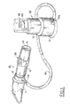
- Fig. 1 is a perspective view of a single patient use respiratory therapy device incorporating a pressure range monitoring unit to provide the user with visual feed-back for monitoring the administration of positive expiratory pressure (PEP) therapy;
- Fig. 2 is an enlarged cross-sectional view of a portion of the PEP device shown in Fig. 1 to better illustrate the patient input portion of the device;
- Figs. 3 and 4 are cross-sectional views of the patient input portion of
the device illustrated in Fig. 1 taken in the direction of
lines 3--3 and 4--4 of Fig. 2 to better illustrate the internal structure thereof; - Fig. 5 is a perspective view of a modification to the patient input portion of the device;
- Fig. 6 is an enlarged cross-sectional view of the device illustrated in Fig. 5;
- Fig. 7 is an enlarged view of a further modification to the patient input portion of the device with a portion broken away to illustrate the manner in which the device may be modified to accommodate another manner of patient input;
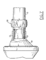
- Fig. 8 is an enlarged cross-sectional view of the pressure range monitoring portion of the device shown in Fig. 1 to better illustrate the components thereof prior to the application of pressure thereto;
- Fig. 9 is an enlarged cross-sectional view of the pressure range monitoring portion of the device shown in Fig. 1 to better illustrate the components thereof upon the application of pressure thereto;
- Fig. 10 is an enlarged horizontal elevation view of the pressure range monitoring portion of the device shown in Fig. 1 to better illustrate the positional relationship of the components thereof.
-
- Referring now to the drawings, there is shown in Fig. 1 a PEP therapy device constructed in accordance with the present invention. The device includes a
patient input portion 10, through which a patient breathes, connected to a pressurerange monitor portion 50 by aflexible conduit 30 through which expiratory air pressure is coupled for a purpose and in a manner to be described in detail hereinafter. Theinput portion 10 includes anexpiratory pressure controller 20, or orifice selector for setting the appropriate expiratory flow/pressure relationship for the patient's condition for therapy purposes. The pressurerange monitor portion 50 provides a visual indicator to the patient that the expiratory pressure being applied is in the predetermined desired range for proper therapy administration. Thepressure range monitor 50 has aremovable base 51 for cleaning purposes to permit the cleaning of condensate which might accumulate. - The
input portion 10 includes amouthpiece 11 through which the patient breathes into the device. As shown in Figs. 1, 2, 5 and 6, themouthpiece 11 is of the type wherein the patient takes the part into the mouth, but the device is not intended to be limited to such applications. Astandard mask 61, such as shown in Fig. 7 as a commercially available anesthesia mask, or a trach adapter can also be utilized. To this end theinput body 12 is sized to have a mask/mouthpiece receiving port 13 of 22mm OD to accept a standard 22mm ID mouthpiece or a 22mm ID mask, as well as aninlet port 15 of 22mm OD to accept a standard 22mm ID fitting for connection to standard respiratory equipment. As best shown in Figs. 1 and 2, a preferred embodiment incorporated atee portion 14 between themouthpiece 11 andinput body 12. Thetee portion 14 has adischarge port 14a for connecting toconduit 30. - The
inlet port 15 incorporates a one-way valve 16 to allow a patient to breath in, but prevents breathing out through theinlet 15. This one-way valve in the preferred embodiment is preferably made of a rigid injection-molded plastic frame and a flexiblesilicone rubber disc 16a. In use, air is drawn into theinput body 12 through the one-way valve 16, positioned at theinlet port 15, which opens to allow the patient to inhale substantially resistance free. Upon exhalation, air is prevented from exiting through theinlet port 15 by the closing of this valve. Therefore, the expiratory air must exit through anexpiratory pressure controller 20 incorporated in theinput body 12 in a manner to be hereinafter described in detail. - In order for a patient to be able to monitor the device when in use, to ensure that the PEP therapy is being properly administered, the
input body 12 is connected to the pressurerange monitoring unit 50, the details of which are best illustrated in Figs. 8-10. Aflexible conduit 30 is coupled at one end to thetee body 14, through thepressure port 14a, to apply the air pressure created by the patient during exhalation to the pressurerange monitoring unit 50, through thepressure inlet port 52a. - The pressure
range monitoring unit 50 includes abellows 53 carried within ahousing 54. The interior of thehousing 54 is formed with a sealedlower portion 54a defined by the inner face ofbellows seal 53 with the only air inlet or outlet being thepressure inlet port 52a through which pressurized air is introduced when a patient exhales into themouthpiece 11. Effecting the seal for thehousing 54 is thebellows seal 53 which is sealed by an "O" ring 53a, which is an integral part of thebellows seal 53, between an upper and the sealed lower portions of thehousing 54 to effect a seal therebetween. The upper portion or top of thehousing 54b is joined to thelower portion 54a of thehousing 54 to capture the O-ring 53a therebetween effecting a pressure tight seal betweenbellows seal 53 and thelower portion 54a of the housing. Theupper portion 54b of thehousing 54 is open to atmosphere allowing air to escape from the upper portion thereby permitting the pressure differential to move theindicator 60. In this manner when air pressure is introduced into the housing through thepressure inlet port 52a, thebellows 53 will be moved in response to the increase in air pressure. - As previously disclosed, in the preferred embodiment the
housing 54 locks air-tight into thebase 51 when in use. Because thebase 51 can be removed, for example to rinse the pressure chamber with disinfectant, aprotective grate 54c is formed as a portion of the open end of thehousing 54 to protect thebellows 53 when thebase 51 is so removed. Astop 54d, best illustrated in Figs. 8 and 9, is carried by thegrate 54c to limit the downward travel of theindicator 60. When assembled, thebase 51 forms a snap-lock seal with complementary ridges 51a on the open end of thehousing 54 so an effective air-tight seal is formed. Other manners of making a suitable removable air-tight seal, such as a twist-lock or threaded cap, would be known to those skilled in the art. In addition, thebase 51 could be permanently sealed if the removal feature was not desired. - To enable the patient to monitor the exhalation pressure being exerted when exhaling, an
indicator 60 is utilized which provides a visual display to the patient when the invention is in use. For this purpose theindicator 60 is secured at a lower end to the top of the bellows seal 53, to the closed face thereof, and extends upwardly within thetop portion 54b of thehousing 54. Theindicator 60 extends upwardly through an opening in aflange portion 65 such that the end thereof is guided during movement by theflange 65, the lower face of which functions as a stop for one end of acompression spring 67. Thecompression spring 67 is supported about theindicator 60 with its other end carried within anupturned cup portion 60a of theindicator 60. The uppermost end or rim of upturned orcup portion 60a also functions as a stop to limit the upward travel of theindicator 60 by engaging theflange 65. A further beneficial result obtained from using the cupped shapedupturned portion 60a is that during movement the bellows seal 53 is properly formed to keep it round. This prevents the bellows seal 53 from developing corners which could increase seal drag or resistance to movement. - The
compression spring 67 provides a force against movement of thebellows 53 so that the amount of pressure applied within thehousing 54 by the patients exhalation provides a nearly linear relationship with movement of theindicator 60. Accordingly, thespring 67 is designed to give a linear or nearly linear movement to theindicator 60 with increasing pressure in thehousing 54. To facilitate expiratory pressure being applied against the closed face of thebellows 53 when a patient begins use of the invention, the at rest position of thebellows 53 against thestop 54d spaces the face thereof off the housing floor as best shown in Fig. 8. - This
upper portion 54b of thehousing 54 also hasindicator markings 66 carried thereon to display to the patient when a predetermined expiratory pressure is being applied. In the embodiment illustrated, when the indicator top is lined up with the lower marking or line, the pressure is at the bottom of the prescribed range. When the indicator top lines up with the upper mark, the pressure is at the top of the pressure range. When the indicator top is in between the upper and lower markings, the pressure is in the correct range for administration of the proper therapy. While this is the preferable manner of providing the patient with a visual display that the invention is being properly used, alternatively theindicator 60 may be marked with indicia, such as a band, or bands, of color which when visible corresponds to the presence of a desired pressure being exerted by the patient. - As previously disclosed, in order for a patient to create a desired expiratory pressure, the
expiratory pressure controller 20 is incorporated into theinput body 12. Theexpiratory pressure controller 20, the internal construction of which is best illustrated in Figs. 2-4, is positioned in the input body to control the flow rate of the patient's expiratory air, and thereby induce a desired expiratory pressure in the patient's lungs which can be monitored by the pressurerange monitoring unit 50. Thecontroller 20 includes aselector dial 21 havingindicia 21a marked thereon to correspond to different-sized openings 22 formed in anapertured face plate 23 which functions to support theselector dial 21 for selective rotation upon ahub 17 formed within theinput body 12. While a preferred embodiment utilizes different-sized openings 22 in theface plate 23, it is to be understood that an alternative embodiment could utilize a slot, shown byreference numeral 22a, in theface plate 23 so that theslot 22a can be positioned relative to theopening 18a inplate 18 to vary the size of the opening through which air is passed. Thehub 17 is supported within theinput body 12 by aplate 18 which closes the interior of theinput body 12 to the passage of air except through anaperture 18a formed therein and the open interior portion of thehub 17. - In operation, when a patient inhales air is drawn into the
input body 12 through theinlet 15, through the one-way valve 16, and passes through thecentral opening 17a ofhub 17 whereby the air is freely drawn into the patient's lungs substantially resistance free. When the patient exhales, however, the one-way valve 16 closes preventing discharge of air out through theopening 17a in the hub and theinlet 15 of the input body. Upon exhalation air is permitted to discharge only through theopening 18a and one of the selectedopenings 22 of theselector dial 21 when aligned therewith. A one-way outlet valve 19, through which the expiratory air is passed, assures that upon inspiration all air comes through the inlet. In this manner, there will be no dilution of any adjunct therapies which might be connected to theinlet 15 of theinput body 12 for use in conjunction with the device, such as aerosolized medicine or an incentive spirometer. - The flow of expiratory air controlled in this manner passes out through a one-
way valve 19, and is discharged from theinput body 12 through the space between the input body and theselector dial 21. Because the flow rate of expiratory air is so controlled, a back pressure is created in the patient's lungs, which is also applied to the pressure range monitor 50 through thepressure port 14a to enable the patient to monitor the expiratory air pressure. By selectively rotating thedial 21, different sized openings can be utilized to control the expiratory air discharge rate and, therefore, the expiratory air pressure applied by the patient. - In the embodiment shown in Figs. 5 and 6, where like reference numerals indicate parts corresponding to those previously described, the mouthpiece can be connected directly to the
input body 12 without thetee portion 14. This would allow a patient to perform short term therapy, relying on the patients ability to feel the lung pressure generated to approximate, by memory, the correct pressure range. However, the patient would not be able to have a visual monitor of the pressure being applied, and such use is not recommended other than for short time periods. - While the invention has been described with reference to preferred embodiments, it will be understood by those skilled in the art that various changes may be made and equivalents may be substituted for elements thereof without departing from the invention. In addition, many modifications may be made to adapt a particular situation or material to the teachings of the invention without departing from the essential scope thereof. Therefore, it is intended that the invention not be limited to the particular embodiments disclosed in the specification and shown in the drawings as the best way presently known for carrying out this invention, but that the invention will include all embodiments falling within the scope of the appended claims.
Claims (12)
- A respiratory therapy device which monitors selectively controlled resistance exhalation comprising:characterized :a housing (10) having an outlet opening (18a) through which a patient to be treated passes expiratory air, and an input opening (15) into which a patient to be treated exhales for establishing a patient generated expiratory air flow ;air flow control means (20) carried by said housing (10) for controlling the flow rate of expiratory air passing from said outlet opening (18a) to thereby induce an expiratory pressure in the patient's lungs upon generation of an expiratory air flow, said air flow control means being movably operable to selectively vary the flow rate expiratory air passing from said outlet opening (18a) for changing the expiratory pressure in response thereto ;a pressure monitor (50) in fluid communication with said housing (10) said pressure monitor being actuable in response to the expiratory pressure in said housing (10) ;and indicia means integrally connected with said pressure monitor (50) to enable a patient to establish and maintain a desired expiratory air pressure in response to said indicia means ;in that said air flow control means (20) includes a fixed plate (18) having an orifice (18a) formed therein through which expiratory air is passed to said outlet opening, and a rotatable plate (23) coaxially aligned therewith and having a plurality of different sized openings (22) formed therein, each one of said different sized opening in said rotatable plate being mutually exclusively positionable into alignment with said orifice (18a) formed in said fixed plate (18) to control the flow rate of expiratory air passed therethrough,in that said housing (10) includes an inlet opening (15) through which the patient draws inspiratory air substantially resistance free,and in that said housing (10) defines a path of substantially resistance free inspiratory air movement through said inlet opening (15) and a one-way valve (16) to a patient mouthpiece (11), and a path of variable resistance expiratory air movement from the patient mouthpiece (11) through said orifice (18a) and one of the mutually exclusively positionable openings (22) aligned with said orifice (18a) to create a variable resistance to the passage of expiratory air from the patient.
- A respiratory therapy device which monitors selectively controlled resistance exhalation comprising :characterized:a housing (10) having an outlet opening (18a) through which a patient to be treated passes expiratory air, and an input opening (15) into which a patient to be treated exhales for establishing a patient generated expiratory air flow;air flow control means (20) carried by said housing (10) for controlling the flow rate of expiratory air passing from said outlet opening (18a) to thereby induce an expiratory pressure in the patient's lungs upon generation of an expiratory air flow, said air flow control means being movably operable to selectively vary the flow rate expiratory air passing from said outlet opening (18a) for changing the expiratory pressure in response thereto ;a pressure monitor (50) in fluid communication with said housing (10) said pressure monitor being actuable in response to the expiratory pressure in said housing (10) ;and indicia means integrally connected with said pressure monitor (50) to enable a patient to establish and maintain a desired expiratory air pressure in response to said indicia means;in that said air flow control means (20) includes a fixed plate (18) having an orifice (18a) formed therein through which expiratory air is passed to said outlet opening, and a rotatable plate (23) coaxially aligned therewith and having a slot (22a) formed therein, said slot being positionable relative to said orifice (18a) formed in said fixed plate (18) to control the flow rate of expiratory air passed therethrough,in that said housing (10) includes an inlet opening (15) through which the patient draws inspiratory air substantially resistance free ;and in that said housing (10) defines a path of substantially resistance free inspiratory air movement through said inlet opening (15) and a one-way valve (16) to a patient mouthpiece (11), and a path of variable resistance expiratory air movement from the patient mouthpiece (11) through said orifice (18a) and said slot (22a) being positionned relative to said orifice (18a) to create a variable resistance to the passage of expiratory air from the patient.
- The respiratory therapy device according to claim 1 and 2, characterized in that said one-way valve means (16) carried by said housing (10) to pass inspiratory air thereinto substantially resistance free prevents discharge of expiratory air from said housing except through said outlet opening.
- The respiratory therapy device according to claims 1 to 3, characterized in that said mouthpiece (11) coupled to said input opening (15) of said housing (10) is intended to facilitate the discharge of patient-generated expiratory air thereinto.
- The respiratory therapy device according to claims 1 to 4, characterized in that it further includes a mask (61) coupled to said input opening (15) of said housing (10) for engaging at least a portion of a patient's face to facilitate the discharge of patient-generated expiratory air thereinto.
- The respiratory therapy device according to claims 1 to 5, wherein said pressure monitor (50) includes a sealed chamber having a seal (53) movable in response to changes in the expiratory pressure applied to said pressure monitor.
- The respiratory therapy device according to claim 6, characterized in that it further includes means (67) for biasing the movement of said seal (53) against the expiratory pressure applied to said pressure monitor (50).
- The respiratory therapy device according to claim 7, wherein said indicia means (60) is supported by said seal (53) for movement therewith.
- The respiratory therapy device according to claim 1, wherein said second plate (23) is provided with at least two openings (22, 22a) of different sizes formed therein which are mutually exclusively positionable in alignment with the orifice (18a) formed is said first plate (18) for changing the size of the opening through which the expiratory air must pass to thereby induce an expiratory pressure in the patient's lungs, wherein said pressure monitor (50) includes a pressure chamber having a movable seal (53) displaceable in response to expiratory air pressure applied to said pressure chamber, wherein said indicia display indicator (60) is operatively connected to said movable seal (53) ; and wherein it further comprises a compression spring (67) coaxially positioned about said indicator (60) to apply a biasing force thereto against the movement of said movable seal (53).
- The respiratory therapy device according to claim 9, wherein said compression spring (67) provides substantially linear movement of said indicator (60) in response to expiratory pressure applied to said pressure chamber.
- A respiratory therapy device according to claims 1 to 10, wherein said air flow controller (20) includes :a first plate (18) interposed in the path of expiratory air flow and having an orifice (18a) formed therein through which the expiratory air must pass and a hollow hub potion (17) through which inspiratory air may freely pass to said input opening;one-way valve (19) carried on said hub portion to permit the discharge of expiratory air through said discharge outlet but block the passage of inspiratory air therethrough.
- The respiratory therapy device according to claim 11, wherein said selectively rotatable second plate (23) carried on said hub portions has an elongated slot (22a) formed therein which is positionable relative to said orifice (18a) formed in said fixed plate (18) to control the flow rate of expiratory air passed therethrough.
Applications Claiming Priority (2)
| Application Number | Priority Date | Filing Date | Title |
|---|---|---|---|
| US08/230,547 US5598839A (en) | 1994-04-20 | 1994-04-20 | Positive expiratory pressure device |
| US230547 | 1994-04-20 |
Publications (3)
| Publication Number | Publication Date |
|---|---|
| EP0678306A2 EP0678306A2 (en) | 1995-10-25 |
| EP0678306A3 EP0678306A3 (en) | 1996-01-17 |
| EP0678306B1 true EP0678306B1 (en) | 2001-11-07 |
Family
ID=22865631
Family Applications (1)
| Application Number | Title | Priority Date | Filing Date |
|---|---|---|---|
| EP95420098A Expired - Lifetime EP0678306B1 (en) | 1994-04-20 | 1995-04-11 | Positive expiratory pressure device |
Country Status (3)
| Country | Link |
|---|---|
| US (1) | US5598839A (en) |
| EP (1) | EP0678306B1 (en) |
| DE (1) | DE69523657T2 (en) |
Cited By (2)
| Publication number | Priority date | Publication date | Assignee | Title |
|---|---|---|---|---|
| US8074641B2 (en) | 2002-05-02 | 2011-12-13 | Pre Holdings, Inc. | Aerosol medication inhalation system |
| US11452838B2 (en) | 2011-04-28 | 2022-09-27 | Michael J. Rusher | Positive expiratory pressure devices with flutter valve |
Families Citing this family (74)
| Publication number | Priority date | Publication date | Assignee | Title |
|---|---|---|---|---|
| US5823179A (en) * | 1996-02-13 | 1998-10-20 | 1263152 Ontario Inc. | Nebulizer apparatus and method |
| US5878743A (en) * | 1996-09-23 | 1999-03-09 | Respironics, Inc. | Pressure sensitive flow control valve |
| US5925831A (en) * | 1997-10-18 | 1999-07-20 | Cardiopulmonary Technologies, Inc. | Respiratory air flow sensor |
| USD413825S (en) * | 1998-09-14 | 1999-09-14 | Cardiopulmonary Technologies, Inc. | Respiratory air flow measuring device |
| WO2000027455A1 (en) * | 1998-11-06 | 2000-05-18 | Salter Labs | Nebulizer mouthpiece and accessories |
| US6581598B1 (en) | 1999-11-24 | 2003-06-24 | Dhd Healthcare Corporation | Positive expiratory pressure device |
| US7059324B2 (en) * | 1999-11-24 | 2006-06-13 | Smiths Medical Asd, Inc. | Positive expiratory pressure device with bypass |
| US6776159B2 (en) * | 1999-11-24 | 2004-08-17 | Dhd Healthcare Corporation | Positive expiratory pressure device with bypass |
| CA2826724C (en) | 2000-04-11 | 2016-02-02 | Trudell Medical International | Aerosol delivery apparatus with positive expiratory pressure capacity |
| US6568387B2 (en) | 2000-07-19 | 2003-05-27 | University Of Florida | Method for treating chronic obstructive pulmonary disorder |
| US9132253B2 (en) * | 2001-02-23 | 2015-09-15 | Lawrence A. Lynn | Asthma resuscitation system and method |
| CA2809180C (en) | 2001-03-20 | 2015-06-02 | Trudell Medical International | Nebulizer apparatus with an adjustable fluid orifice |
| DE10126633B4 (en) * | 2001-05-31 | 2005-11-24 | Heptec Gmbh | Breathing valve for CPAP devices |
| AU2003205263A1 (en) | 2002-01-22 | 2003-09-02 | University Of Florida | Pressure relief valve |
| US6904908B2 (en) | 2002-05-21 | 2005-06-14 | Trudell Medical International | Visual indicator for an aerosol medication delivery apparatus and system |
| WO2004096110A2 (en) * | 2003-04-28 | 2004-11-11 | Chi, Llc | Pursed lip breathing device |
| US7878980B2 (en) | 2003-06-13 | 2011-02-01 | Treymed, Inc. | Gas flow diverter for respiratory monitoring device |
| CN101683546A (en) * | 2004-04-09 | 2010-03-31 | 雷斯梅德有限公司 | Nasal assembly |
| US10610228B2 (en) | 2004-12-08 | 2020-04-07 | Theravent, Inc. | Passive nasal peep devices |
| SE531316C2 (en) | 2005-04-19 | 2009-02-17 | Kenneth Eliasson | An adjustable breathing resistance |
| US7909033B2 (en) | 2006-05-03 | 2011-03-22 | Comedica Incorporated | Breathing treatment apparatus |
| US8051854B2 (en) * | 2006-09-15 | 2011-11-08 | Comedica Incorporated | Continuous high-frequency oscillation breathing treatment apparatus |
| US8225785B2 (en) * | 2006-10-03 | 2012-07-24 | Smiths Medical Asd, Inc. | Vibratory PEP therapy system with medicated aerosol nebulizer |
| US20080086065A1 (en) * | 2006-10-06 | 2008-04-10 | Holm Karen B | Cough assistance and airway clearance device |
| US7779841B2 (en) | 2006-11-13 | 2010-08-24 | Carefusion 2200, Inc. | Respiratory therapy device and method |
| US8528547B2 (en) * | 2007-04-02 | 2013-09-10 | Carefusion 2200, Inc. | High frequency oscillation respiratory therapy |
| US9050434B2 (en) * | 2007-05-18 | 2015-06-09 | Comedica Incorporated | Lung therapy device |
| EP2249907B1 (en) * | 2008-02-01 | 2013-09-04 | Theravent Inc | Cpap interface and backup devices |
| EP2338575B1 (en) | 2008-02-21 | 2017-05-31 | Trudell Medical International | Respiratory muscle endurance training device and method for the use thereof |
| US8251876B2 (en) * | 2008-04-22 | 2012-08-28 | Hill-Rom Services, Inc. | Breathing exercise apparatus |
| US8539951B1 (en) | 2008-05-27 | 2013-09-24 | Trudell Medical International | Oscillating positive respiratory pressure device |
| US8327849B2 (en) | 2008-10-28 | 2012-12-11 | Trudell Medical International | Oscillating positive expiratory pressure device |
| US8485179B1 (en) | 2009-02-23 | 2013-07-16 | Trudell Medical International | Oscillating positive expiratory pressure device |
| US9149589B2 (en) | 2009-02-23 | 2015-10-06 | Trudell Medical International | Method and device for performing orientation dependent oscillating positive expiratory pressure therapy |
| WO2011004274A1 (en) * | 2009-07-09 | 2011-01-13 | Koninklijke Philips Electronics, N.V. | System and method for entraining the breathing of a subject |
| US9151425B2 (en) * | 2009-11-02 | 2015-10-06 | Comedica Incorporated | Multiple conduit connector apparatus and method |
| US20110100360A1 (en) * | 2009-11-02 | 2011-05-05 | Joseph Dee Faram | Composite lung therapy device and method |
| EP2444114B1 (en) * | 2010-10-20 | 2016-09-28 | Hill-Rom Services Pte. Ltd. | Apparatus for positive expiratory pressure therapy |
| RU2615280C2 (en) | 2011-06-06 | 2017-04-04 | Труделл Медикал Интернешнл | Device with oscillatory positive pressure at exhalation |
| US9180271B2 (en) * | 2012-03-05 | 2015-11-10 | Hill-Rom Services Pte. Ltd. | Respiratory therapy device having standard and oscillatory PEP with nebulizer |
| US9517315B2 (en) | 2012-11-30 | 2016-12-13 | Trudell Medical International | Oscillating positive expiratory pressure device |
| US9795752B2 (en) | 2012-12-03 | 2017-10-24 | Mhs Care-Innovation, Llc | Combination respiratory therapy device, system, and method |
| CA2915949C (en) | 2013-07-12 | 2020-01-28 | Trudell Medical International | Huff cough simulation device |
| US9849257B2 (en) | 2013-08-22 | 2017-12-26 | Trudell Medical International | Oscillating positive respiratory pressure device |
| US10363383B2 (en) | 2014-02-07 | 2019-07-30 | Trudell Medical International | Pressure indicator for an oscillating positive expiratory pressure device |
| US20150224270A1 (en) * | 2014-02-12 | 2015-08-13 | Justin Frandson | Resistance breathing device |
| US10729873B2 (en) * | 2014-04-15 | 2020-08-04 | Fundación Valle Del Lili | T-device with one-way valve, flow-occlusion/release system, and pressure release valve |
| EP3229883A1 (en) * | 2014-12-11 | 2017-10-18 | Smiths Medical International Limited | Respiratory therapy apparatus |
| US10004872B1 (en) | 2015-03-06 | 2018-06-26 | D R Burton Healthcare, Llc | Positive expiratory pressure device having an oscillating valve |
| US10039892B2 (en) | 2015-03-25 | 2018-08-07 | Diane Miller | Pediatric induction of anesthesia |
| CN107735135B (en) | 2015-04-02 | 2020-06-26 | 希尔-罗姆服务私人有限公司 | Manifold for a respiratory device |
| DE102015214141A1 (en) * | 2015-07-27 | 2017-02-02 | Daniel Peller | Respiratory therapy device |
| MX2018001321A (en) | 2015-07-30 | 2018-08-15 | Trudell Medical Int | Combined respiratory muscle training and oscillating positive expiratory pressure device. |
| USD778429S1 (en) | 2015-09-02 | 2017-02-07 | Trudell Medical International | Respiratory treatment device |
| USD780906S1 (en) | 2015-09-02 | 2017-03-07 | Trudell Medical International | Respiratory treatment device |
| US10857317B2 (en) | 2015-12-04 | 2020-12-08 | Trudell Medical International | Huff cough simulation device |
| US10850050B2 (en) | 2016-05-19 | 2020-12-01 | Trudell Medical International | Smart valved holding chamber |
| WO2018007997A1 (en) | 2016-07-08 | 2018-01-11 | Trudell Medical International | Smart oscillating positive expiratory pressure device |
| US10786638B2 (en) | 2016-07-08 | 2020-09-29 | Trudell Medical International | Nebulizer apparatus and method |
| US20190099576A1 (en) * | 2016-12-05 | 2019-04-04 | Medipines Corporation | Breathing tube assembly for respiratory gas measurement for steady-state breathing |
| ES2920151T3 (en) | 2016-12-09 | 2022-08-01 | Trudell Medical Int | smart nebulizer |
| EP3618908A4 (en) | 2017-05-03 | 2021-01-13 | Trudell Medical International | Combined oscillating positive expiratory pressure therapy and huff cough simulation device |
| US11439869B2 (en) | 2017-05-19 | 2022-09-13 | Trudell Medical International | Positive expiratory pressure device |
| CN111818848A (en) * | 2017-12-27 | 2020-10-23 | 皇家飞利浦有限公司 | Expiratory airflow limitation detection via airflow blocker modulation |
| MX2020007026A (en) | 2018-01-04 | 2020-12-03 | Trudell Medical Int | Smart oscillating positive expiratory pressure device. |
| US10953278B2 (en) | 2018-02-02 | 2021-03-23 | Trudell Medical International | Oscillating positive expiratory pressure device |
| USD903097S1 (en) | 2018-05-18 | 2020-11-24 | Trudell Medical International | Mask |
| USD874064S1 (en) | 2018-05-18 | 2020-01-28 | Trudell Medical International | Mask |
| USD919080S1 (en) * | 2018-05-30 | 2021-05-11 | Medipines Corporation | Breathing tube connector for a respiratory gas exchange monitor |
| USD926308S1 (en) * | 2018-05-30 | 2021-07-27 | Medipines Corporation | Breathing tube for a respiratory gas exchange monitor |
| USD893806S1 (en) | 2018-11-09 | 2020-08-18 | Trudell Medical Internationl | Mask and shroud |
| US10780318B1 (en) * | 2019-04-18 | 2020-09-22 | Firas Kasem Ghazzawi | Breathing device with exhale and inhale valve to create resistance |
| EP4021542A4 (en) | 2019-08-27 | 2023-09-06 | Trudell Medical International | Smart oscillating positive expiratory pressure device |
| CN115350454B (en) * | 2022-09-20 | 2023-12-15 | 上海市浦东新区肺科医院(上海市浦东新区第二红十字老年护理院) | Special rehabilitation exercise equipment for pulmonary tuberculosis patients |
Family Cites Families (21)
| Publication number | Priority date | Publication date | Assignee | Title |
|---|---|---|---|---|
| US3511228A (en) * | 1964-06-04 | 1970-05-12 | Claes Erik Gunnar Lundgren | Bronchial dilator for patients suffering from emphysema and asthma or the like |
| GB1073262A (en) * | 1964-12-11 | 1967-06-21 | Garbe Dietmar Rudolf | Volumetric measuring apparatus |
| CH539437A (en) * | 1971-09-23 | 1973-07-31 | Siemens Ag | Device for medical purposes for infusing a liquid, in particular when measuring blood pressure |
| US3826247A (en) * | 1972-06-27 | 1974-07-30 | A Ruskin | Pulmonary achievement trainer |
| US3933171A (en) * | 1974-04-09 | 1976-01-20 | Airco, Inc. | Anesthesia breathing circuit with positive end expiratory pressure valve |
| FR2287247A1 (en) * | 1974-10-11 | 1976-05-07 | Artaud Michel | Medical rehabilitation of respiratory system - by adjusting breathing of patient shown on screen as trace to ideal trace |
| US3993050A (en) * | 1975-05-19 | 1976-11-23 | Searle Cardio-Pulmonary Systems Inc. | Spirometer |
| US4062358A (en) * | 1976-04-21 | 1977-12-13 | Kritzer Richard W | Respirators |
| US4158360A (en) * | 1978-01-26 | 1979-06-19 | Projects In Health, Inc. | Expiratory flow meter |
| US4421120A (en) * | 1981-03-02 | 1983-12-20 | Biotrine Corporation | Peak respiratory flow monitor |
| US4736750A (en) * | 1981-04-24 | 1988-04-12 | Valdespino Joseph M | Apparatus for testing pulmonary functions |
| US4768520A (en) * | 1981-05-06 | 1988-09-06 | Varraux Alan R | Peak flow and pulmonary incentive meter |
| US4403616A (en) * | 1981-06-09 | 1983-09-13 | K-Med, Inc. | Expiratory breathing exercise device |
| US4533137A (en) * | 1982-01-19 | 1985-08-06 | Healthscan Inc. | Pulmonary training method |
| US4446863A (en) * | 1982-04-16 | 1984-05-08 | Howard Rubin | Connector for inhalation therapy apparatus |
| US4601465A (en) * | 1984-03-22 | 1986-07-22 | Roy Jean Yves | Device for stimulating the human respiratory system |
| US4706685A (en) * | 1986-09-15 | 1987-11-17 | Jones Jr William C | Spirometer with double rolling seals |
| US4944306A (en) * | 1987-10-13 | 1990-07-31 | Healthscan, Inc. | Spirometer for pulmonary measurement |
| DK168888A (en) * | 1988-03-25 | 1989-09-26 | Ambu Int As | RESPIRATION TRAINING DEVICE |
| EP0372148A1 (en) * | 1988-12-09 | 1990-06-13 | Erik Folke Norell | Lung exercising device |
| US5320107A (en) * | 1992-12-24 | 1994-06-14 | Brien Kevin P O | Spirometer with zone graph |
-
1994
- 1994-04-20 US US08/230,547 patent/US5598839A/en not_active Expired - Lifetime
-
1995
- 1995-04-11 EP EP95420098A patent/EP0678306B1/en not_active Expired - Lifetime
- 1995-04-11 DE DE69523657T patent/DE69523657T2/en not_active Expired - Lifetime
Cited By (5)
| Publication number | Priority date | Publication date | Assignee | Title |
|---|---|---|---|---|
| US8074641B2 (en) | 2002-05-02 | 2011-12-13 | Pre Holdings, Inc. | Aerosol medication inhalation system |
| US8459252B2 (en) | 2002-05-02 | 2013-06-11 | Pari Innovative Manufacturers, Inc. | Aerosol medication inhalation system |
| US8973571B1 (en) | 2002-05-02 | 2015-03-10 | Pre Holding, Inc. | Aerosol medication inhalation system |
| US9308335B2 (en) | 2002-05-02 | 2016-04-12 | Pre Holding, Inc. | Aerosol medication inhalation system |
| US11452838B2 (en) | 2011-04-28 | 2022-09-27 | Michael J. Rusher | Positive expiratory pressure devices with flutter valve |
Also Published As
| Publication number | Publication date |
|---|---|
| US5598839A (en) | 1997-02-04 |
| EP0678306A2 (en) | 1995-10-25 |
| DE69523657D1 (en) | 2001-12-13 |
| EP0678306A3 (en) | 1996-01-17 |
| DE69523657T2 (en) | 2002-05-08 |
Similar Documents
| Publication | Publication Date | Title |
|---|---|---|
| EP0678306B1 (en) | Positive expiratory pressure device | |
| US8663069B2 (en) | Respiratory muscle endurance training device and method for the use thereof | |
| US8758202B2 (en) | Respiratory muscle endurance training device and method for the use thereof | |
| US4210155A (en) | Inspirational inhalation spirometer apparatus | |
| US6986349B2 (en) | Systems and methods for enhancing blood circulation | |
| EP1435251B1 (en) | Positive expiratory pressure device with bypass | |
| JPH02182277A (en) | Treating apparatus | |
| JP2000152993A (en) | Improved artificial respirator starter | |
| WO2002015968A2 (en) | Flow control valve for manual resuscitator devices | |
| AU2013363363A1 (en) | Nebulizer with integrated breathing incentive | |
| CN113181603A (en) | Big data recording's cardiothoracic surgery patient nursing is with lung training device that exhales | |
| US20130204151A1 (en) | Augmented Incentive Spirometer | |
| KR20230016165A (en) | Inspiratory resistance valve system with expiratory port | |
| US20140352691A1 (en) | Adjustable and biased-open unidirectional speaking valve | |
| EP3682923B1 (en) | Medication inhaler for aerosol pulmonary delivery with visual feedback system | |
| Phillips et al. | Manual resuscitators and portable ventilators | |
| SU1722507A1 (en) | Device for prophylaxis of respiratory system diseases | |
| CA2226646A1 (en) | Canadian lung care device |
Legal Events
| Date | Code | Title | Description |
|---|---|---|---|
| PUAI | Public reference made under article 153(3) epc to a published international application that has entered the european phase |
Free format text: ORIGINAL CODE: 0009012 |
|
| AK | Designated contracting states |
Kind code of ref document: A2 Designated state(s): DE FR GB IE IT NL |
|
| PUAL | Search report despatched |
Free format text: ORIGINAL CODE: 0009013 |
|
| AK | Designated contracting states |
Kind code of ref document: A3 Designated state(s): DE FR GB IE IT NL |
|
| 17P | Request for examination filed |
Effective date: 19960620 |
|
| 17Q | First examination report despatched |
Effective date: 19990201 |
|
| GRAG | Despatch of communication of intention to grant |
Free format text: ORIGINAL CODE: EPIDOS AGRA |
|
| GRAG | Despatch of communication of intention to grant |
Free format text: ORIGINAL CODE: EPIDOS AGRA |
|
| GRAH | Despatch of communication of intention to grant a patent |
Free format text: ORIGINAL CODE: EPIDOS IGRA |
|
| RAP1 | Party data changed (applicant data changed or rights of an application transferred) |
Owner name: DHD HEALTHCARE CORPORATION |
|
| GRAH | Despatch of communication of intention to grant a patent |
Free format text: ORIGINAL CODE: EPIDOS IGRA |
|
| GRAA | (expected) grant |
Free format text: ORIGINAL CODE: 0009210 |
|
| GRAH | Despatch of communication of intention to grant a patent |
Free format text: ORIGINAL CODE: EPIDOS IGRA |
|
| AK | Designated contracting states |
Kind code of ref document: B1 Designated state(s): DE FR GB IE IT NL |
|
| PG25 | Lapsed in a contracting state [announced via postgrant information from national office to epo] |
Ref country code: NL Free format text: LAPSE BECAUSE OF FAILURE TO SUBMIT A TRANSLATION OF THE DESCRIPTION OR TO PAY THE FEE WITHIN THE PRESCRIBED TIME-LIMIT Effective date: 20011107 Ref country code: IT Free format text: LAPSE BECAUSE OF FAILURE TO SUBMIT A TRANSLATION OF THE DESCRIPTION OR TO PAY THE FEE WITHIN THE PRESCRIBED TIME-LIMIT;WARNING: LAPSES OF ITALIAN PATENTS WITH EFFECTIVE DATE BEFORE 2007 MAY HAVE OCCURRED AT ANY TIME BEFORE 2007. THE CORRECT EFFECTIVE DATE MAY BE DIFFERENT FROM THE ONE RECORDED. Effective date: 20011107 |
|
| REG | Reference to a national code |
Ref country code: IE Ref legal event code: FG4D |
|
| REF | Corresponds to: |
Ref document number: 69523657 Country of ref document: DE Date of ref document: 20011213 |
|
| ET | Fr: translation filed | ||
| REG | Reference to a national code |
Ref country code: GB Ref legal event code: IF02 |
|
| NLV1 | Nl: lapsed or annulled due to failure to fulfill the requirements of art. 29p and 29m of the patents act | ||
| PLBE | No opposition filed within time limit |
Free format text: ORIGINAL CODE: 0009261 |
|
| STAA | Information on the status of an ep patent application or granted ep patent |
Free format text: STATUS: NO OPPOSITION FILED WITHIN TIME LIMIT |
|
| 26N | No opposition filed | ||
| REG | Reference to a national code |
Ref country code: GB Ref legal event code: 732E |
|
| REG | Reference to a national code |
Ref country code: FR Ref legal event code: TP |
|
| PGFP | Annual fee paid to national office [announced via postgrant information from national office to epo] |
Ref country code: IE Payment date: 20140410 Year of fee payment: 20 Ref country code: GB Payment date: 20140409 Year of fee payment: 20 |
|
| PGFP | Annual fee paid to national office [announced via postgrant information from national office to epo] |
Ref country code: FR Payment date: 20140409 Year of fee payment: 20 Ref country code: DE Payment date: 20140430 Year of fee payment: 20 |
|
| REG | Reference to a national code |
Ref country code: DE Ref legal event code: R071 Ref document number: 69523657 Country of ref document: DE |
|
| REG | Reference to a national code |
Ref country code: GB Ref legal event code: PE20 Expiry date: 20150410 |
|
| REG | Reference to a national code |
Ref country code: IE Ref legal event code: MK9A |
|
| PG25 | Lapsed in a contracting state [announced via postgrant information from national office to epo] |
Ref country code: GB Free format text: LAPSE BECAUSE OF EXPIRATION OF PROTECTION Effective date: 20150410 |
|
| PG25 | Lapsed in a contracting state [announced via postgrant information from national office to epo] |
Ref country code: IE Free format text: LAPSE BECAUSE OF EXPIRATION OF PROTECTION Effective date: 20150411 |