EP0680221A2 - Quantizing image data in image compression - Google Patents
Quantizing image data in image compression Download PDFInfo
- Publication number
- EP0680221A2 EP0680221A2 EP95302153A EP95302153A EP0680221A2 EP 0680221 A2 EP0680221 A2 EP 0680221A2 EP 95302153 A EP95302153 A EP 95302153A EP 95302153 A EP95302153 A EP 95302153A EP 0680221 A2 EP0680221 A2 EP 0680221A2
- Authority
- EP
- European Patent Office
- Prior art keywords
- step size
- quantization
- quantization step
- noise
- saturation
- Prior art date
- Legal status (The legal status is an assumption and is not a legal conclusion. Google has not performed a legal analysis and makes no representation as to the accuracy of the status listed.)
- Granted
Links
Images


Classifications
-
- H—ELECTRICITY
- H04—ELECTRIC COMMUNICATION TECHNIQUE
- H04N—PICTORIAL COMMUNICATION, e.g. TELEVISION
- H04N19/00—Methods or arrangements for coding, decoding, compressing or decompressing digital video signals
- H04N19/10—Methods or arrangements for coding, decoding, compressing or decompressing digital video signals using adaptive coding
- H04N19/102—Methods or arrangements for coding, decoding, compressing or decompressing digital video signals using adaptive coding characterised by the element, parameter or selection affected or controlled by the adaptive coding
- H04N19/124—Quantisation
-
- H—ELECTRICITY
- H04—ELECTRIC COMMUNICATION TECHNIQUE
- H04N—PICTORIAL COMMUNICATION, e.g. TELEVISION
- H04N19/00—Methods or arrangements for coding, decoding, compressing or decompressing digital video signals
- H04N19/44—Decoders specially adapted therefor, e.g. video decoders which are asymmetric with respect to the encoder
- H04N19/45—Decoders specially adapted therefor, e.g. video decoders which are asymmetric with respect to the encoder performing compensation of the inverse transform mismatch, e.g. Inverse Discrete Cosine Transform [IDCT] mismatch
-
- H—ELECTRICITY
- H04—ELECTRIC COMMUNICATION TECHNIQUE
- H04N—PICTORIAL COMMUNICATION, e.g. TELEVISION
- H04N19/00—Methods or arrangements for coding, decoding, compressing or decompressing digital video signals
- H04N19/10—Methods or arrangements for coding, decoding, compressing or decompressing digital video signals using adaptive coding
- H04N19/102—Methods or arrangements for coding, decoding, compressing or decompressing digital video signals using adaptive coding characterised by the element, parameter or selection affected or controlled by the adaptive coding
- H04N19/124—Quantisation
- H04N19/126—Details of normalisation or weighting functions, e.g. normalisation matrices or variable uniform quantisers
-
- H—ELECTRICITY
- H04—ELECTRIC COMMUNICATION TECHNIQUE
- H04N—PICTORIAL COMMUNICATION, e.g. TELEVISION
- H04N19/00—Methods or arrangements for coding, decoding, compressing or decompressing digital video signals
- H04N19/10—Methods or arrangements for coding, decoding, compressing or decompressing digital video signals using adaptive coding
- H04N19/134—Methods or arrangements for coding, decoding, compressing or decompressing digital video signals using adaptive coding characterised by the element, parameter or criterion affecting or controlling the adaptive coding
- H04N19/146—Data rate or code amount at the encoder output
- H04N19/149—Data rate or code amount at the encoder output by estimating the code amount by means of a model, e.g. mathematical model or statistical model
-
- H—ELECTRICITY
- H04—ELECTRIC COMMUNICATION TECHNIQUE
- H04N—PICTORIAL COMMUNICATION, e.g. TELEVISION
- H04N19/00—Methods or arrangements for coding, decoding, compressing or decompressing digital video signals
- H04N19/10—Methods or arrangements for coding, decoding, compressing or decompressing digital video signals using adaptive coding
- H04N19/134—Methods or arrangements for coding, decoding, compressing or decompressing digital video signals using adaptive coding characterised by the element, parameter or criterion affecting or controlling the adaptive coding
- H04N19/157—Assigned coding mode, i.e. the coding mode being predefined or preselected to be further used for selection of another element or parameter
- H04N19/159—Prediction type, e.g. intra-frame, inter-frame or bidirectional frame prediction
-
- H—ELECTRICITY
- H04—ELECTRIC COMMUNICATION TECHNIQUE
- H04N—PICTORIAL COMMUNICATION, e.g. TELEVISION
- H04N19/00—Methods or arrangements for coding, decoding, compressing or decompressing digital video signals
- H04N19/10—Methods or arrangements for coding, decoding, compressing or decompressing digital video signals using adaptive coding
- H04N19/169—Methods or arrangements for coding, decoding, compressing or decompressing digital video signals using adaptive coding characterised by the coding unit, i.e. the structural portion or semantic portion of the video signal being the object or the subject of the adaptive coding
- H04N19/17—Methods or arrangements for coding, decoding, compressing or decompressing digital video signals using adaptive coding characterised by the coding unit, i.e. the structural portion or semantic portion of the video signal being the object or the subject of the adaptive coding the unit being an image region, e.g. an object
- H04N19/176—Methods or arrangements for coding, decoding, compressing or decompressing digital video signals using adaptive coding characterised by the coding unit, i.e. the structural portion or semantic portion of the video signal being the object or the subject of the adaptive coding the unit being an image region, e.g. an object the region being a block, e.g. a macroblock
-
- H—ELECTRICITY
- H04—ELECTRIC COMMUNICATION TECHNIQUE
- H04N—PICTORIAL COMMUNICATION, e.g. TELEVISION
- H04N19/00—Methods or arrangements for coding, decoding, compressing or decompressing digital video signals
- H04N19/60—Methods or arrangements for coding, decoding, compressing or decompressing digital video signals using transform coding
- H04N19/61—Methods or arrangements for coding, decoding, compressing or decompressing digital video signals using transform coding in combination with predictive coding
-
- H—ELECTRICITY
- H04—ELECTRIC COMMUNICATION TECHNIQUE
- H04N—PICTORIAL COMMUNICATION, e.g. TELEVISION
- H04N19/00—Methods or arrangements for coding, decoding, compressing or decompressing digital video signals
- H04N19/10—Methods or arrangements for coding, decoding, compressing or decompressing digital video signals using adaptive coding
- H04N19/134—Methods or arrangements for coding, decoding, compressing or decompressing digital video signals using adaptive coding characterised by the element, parameter or criterion affecting or controlling the adaptive coding
- H04N19/146—Data rate or code amount at the encoder output
- H04N19/152—Data rate or code amount at the encoder output by measuring the fullness of the transmission buffer
Definitions
- the present invention relates to quantizing image data in image compression.
- the Moving Picture Experts Group system (MPEG 1, MPEG 2) has been proposed as an international standard for high efficiency encoding and decoding of a moving picture.
- Three types of pictures are defined in the MPEG system, an I picture which is encoded in a standalone manner, a P picture which is encoded by forward prediction from one reference picture which may be an I picture or a P picture, and a B picture which is bidirectionally encoded by forward and backward prediction from two reference pictures.
- a typical sequence of encoded pictures, in temporal order, may be I B B P B B P B B I B B ...
- a picture is divided into macro blocks.
- An I picture comprises intra-macro blocks.
- P and B pictures respectively comprise non-intra macro blocks.
- Fig. 1 shows a conventional video encoder according to the MPEG system.
- Blocks of data representing an I picture are applied to input terminal 100 and thence to subtractor 107. Since an I picture is not predicted from a reference picture, subtractor 107 simply forwards the I picture data blocks to DCT circuit 101 which orthogonally transforms the picture data blocks to coefficient data blocks, and supplies the blocks of coefficient data to quantizer 102.
- Quantizer 102 quantizes the I picture coefficient data using a quantization step size selected by quantization control circuit 102.
- the quantization step size may also be referred to as a quantization scale.
- the quantized coefficient data are variable length encoded by VLC circuit 103, such as with a two dimensional Huffman code, and supplied to buffer 110.
- Buffer occupancy detecting circuit 117 monitors the percentage of buffer capacity used by the encoded data and supplies buffer occupancy information to the quantization control circuit 108, which selects a quantization step size so that the amount of encoded data in the buffer 110 remains within its capacity, i.e., does not overflow.
- the encoded data is delivered to output terminal 114 for transmission or recording.
- the quantized coefficient data are also supplied to inverse quantizing circuit 109, which dequantizes the quantized data to produce reconstructed coefficient data.
- Inverse DCT circuit 111 inverse orthogonally transforms the reconstructed coefficient data to produce reconstructed image data blocks and supplies the image data blocks to frame memory 105 for storage therein as a locally decoded reference picture.
- blocks of data representing either a B picture or a P picture are applied to terminal 100 and thence to motion detecting circuit 104 which detects motion within the supplied data blocks and produces motion vectors between the input B or P picture blocks and the stored reference picture blocks.
- the motion vectors are supplied to motion compensating circuit 113.
- the reference picture stored in frame memory 105 is motion compensated, that is, modified using the motion vectors by the circuit 113, to produce predicted picture data which is applied to subtractor 107 and adder 112.
- Subtractor 107 subtracts the predicted picture data from the input picture data to produce difference data which is orthogonally transformed, quantized and variable length coded, as generally described above.
- the quantized input picture data are also supplied to inverse quantizing circuit 109 and inverse DCT circuit 111 to produce reconstructed difference data which are added to the image data of the motion compensated reference picture by adder 112.
- the result is stored in frame memory 105 as a new reference picture.
- the encoder of Fig. 1 in order to generate data from the buffer 110 at a predetermined rate, it is necessary to limit the amount of encoded data per predetermined period of time to a predetermined amount.
- the process of limiting operates so that when the amount of encoded data in the buffer 110 is large, the quantization step size is selected to be coarse, and when the amount of encoded data in the buffer 110 is small, the quantization step size is selected to be fine.
- Decreasing the quantization step size to be fine increases the amount of encoded data, and also reduces degradation in the quality of the reconstructed picture. For images having little information, degradation in quality is not such a serious problem, and reduction in the amount of encoded data is desirable.
- a method of and a system for quantization control estimates a quantization noise curve relating quantization noise to quantization step size for a block of image data, and selects an actual quantization step size in accordance with the estimated quantization noise curve.
- the step of and means for estimating includes predicting a saturation noise value, predicting a saturation quantization step size corresponding to the saturated noise value, and predicting the estimated quantization noise curve in accordance with the saturation noise value and the saturation quantization step size.
- a quantization noise curve which will result from quantizing a coefficient data block is estimated and used, along with a specified minimum noise value, to select the quantization step size actually used to quantize the coefficient data block. Consequently, since image quality is incorporated in the selection of the quantization step size, reconstructed pictures have better image quality.
- Encoders according to the present embodiment and in accordance with the MPEG 2 system will now be described. It will be appreciated that encoders in accordance with other systems are also contemplated.
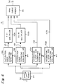
- FIG. 2 there is illustrated an encoder according to the present embodiment.
- the apparatus illustrated in Fig. 2 is similar to the apparatus illustrated in Fig. 1, but also includes noise estimating circuit 15.
- noise estimating circuit 15 For brevity, descriptions of elements of Fig. 2 corresponding to elements of Fig. 1 are omitted.
- the estimating circuit 15 of Fig. 2 is adapted to receive a block of coefficient data from DCT circuit 1, to estimate the noise at various quantization step sizes, as described below. and to supply a predicted noise curve to quantization control circuit 8.
- a quantization noise estimate may be generated directly from the input image data.
- the quantization control circuit 8 functions to select a quantization step size on the basis of the predicted noise curve and the occupancy of buffer 10.
- the buffer occupancy is fed back to the quantization control circuit 8 by buffer occupancy detecting circuit 17.
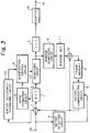
- Fig. 3 illustrates another embodiment of an encoder.
- buffer occupancy estimating circuit 17A instead of feeding back the actual buffer occupancy, buffer occupancy estimating circuit 17A functions to predict the buffer occupancy from the input image data, and to feed forward the predicted buffer occupancy to the quantization control circuit 8.
- Fig. 4 shows a block diagram of the noise estimating circuit 15.
- a coefficient block is supplied to a saturation noise estimating circuit and to a saturation quantization step size estimating circuit. The function of these estimating circuits is discussed below.
- a noise characteristic estimating circuit uses the estimated saturation noise and estimated saturation quantization step size to produce a predicted noise curve.
- the actual noise detecting circuit may be realized in hardware or in software.
- Figs. 6 and 7 show quantization matrices used in the MPEG encoder of Fig. 2 for intra-macro block and non-intra-macro block coefficients, respectively.
- the matrix of Fig. 6 is referred to as wI(i,j), and the matrix of Fig. 7 is referred to as wN(i,j).
- the quantization noise Q_NOISE comprises equiprobable values in the range 0 to QS/2.
- the mean value of the quantization noise is, therefore, QS/4.
- the average noise is a function of the quantization step size QS.
- the quantization noise is referred to herein as "saturated" when the quantization step size satisfies COEF ⁇ QS/2.
- the quantization noise increases with an increase in the quantization step size.
- the quantization noise becomes zero for that quantization step size.
- the following table shows an example of the quantization noise as a function of an increasing quantization step size.
- the root mean square noise NRMS for a block of coefficients is fundamentally proportional to the quantization step size, until the quantization noise saturates at COEF ⁇ QS/2.
- NRMS is set to a constant value.
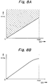
- Figs. 8A and 9A show relationships between the quantization step size QS (abscissa) and the root mean square noise for a coefficient block NRMS (ordinate).
- Fig. 8A shows the case where saturation of NRMS does not occur for a quantization step size up to the maximum quantization step size, QS ⁇ QS_MAX.
- the possible range of NRMS is the shaded portion of Fig. 8A.
- almost all of the values of NRMS are located on the curve shown in Fig. 8B.
- Fig. 8B shows the case where when the quantization scale QS is increased, NRMS increases almost proportionally thereto.
- the quantization scale reaches its maximum value at or before saturation of NRMS.
- Fig. 9A shows the case where saturation of NRMS occurs before the quantization step size QS reaches the maximum quantization step size QS_MAX.
- the possible range of NRMS is the shaded portion of Fig. 9A. However, almost all of the values of NRMS are located on the curve shown in Fig. 9B.
- Fig. 9B shows the case where as the quantization scale QS is increased, NRMS saturates before the quantization scale QS reaches its maximum value.
- the minimum value of the quantization step size at which saturation of NRMS occurs is referred to herein as the saturation quantization step size.
- the maximum value of the quantization step size QS_MAX is 31.
- MPEG 2 provides for a linear quantization scale and a nonlinear quantization scale, only the case of a linear quantization scale will be discussed.
- the coefficients QAC(i,j) are limited to a value within a range from -255 to 255 when tcoef-escape-flag is equal to 0 and to a value within a range from -2047 to 2047 when tcoef-escape-flag is equal to 1.
- dct_recon(0,0) Q_dc x QDC
- dct_recon(0,0) the reconstructed DC coefficient, also referred to as the dequantized DC coefficient.
- dct_recon(i,j) (QS x 2 x QAC(i,j) x wI(i,j)) / 16 where dct-recon(i,j) denotes the reconstructed AC coefficients.
- LSB least significant bit
- the least significant bit (LSB) in the sign-magnitude representation in dct_recon(7,7) is inverted:
- Fig. 11A shows the case where NRMS is completely saturated before the quantization step size reaches its maximum, that is, (b) ⁇ QS_MAX.
- NRMS (a).
- Fig. 11B shows the curve on which NRMS is generally located.
- the quantization noise curve is estimated as follows.
- SNR 20 log (255/NRMS)
- a procedure for estimating the saturation NRMS (a) at the maximum quantization step size QS_MAX will now be described.
- the procedure is to approximately calculate the portion of each coefficient in a block which will be lost (omitted) by quantization, to sum the lost portions in the block and to multiply the sum by a constant found from, for example, statistical observation of encoding sequences.
- the multiplied sum is the prediction of the saturation NRMS (a).
- the sum of the coefficient portions lost during quantization of an intra-macro block is defined as follows:
- the multiplier constant should be obtained by statistics of the relationship between P1I and NRMS for a source image being encoded.
- a procedure for estimating the saturation quantization step size (b) will now be described.
- the procedure is to find the minimum quantization step size which results in the quantized AC coefficients for a block having values of zero, and to use this minimum quantization step size as the prediction of the saturation quantization step size.
- the minimum quantization step size MIN_QSI(i,j) which results in the quantized AC coefficient QAC(i,j) having a value of zero is found from the following, based on equations (4) and (5):
- QAC(i,j) ( ((16 x ac(i,j))/wI(i,j)) + ((3 x QS)/4) ) / (2 x QS)
- the quantized coefficient QAC(i,j) will be zero when: 1 > ( ((16 x ac(i,j))/wI(i,j)) + ((3 x QS)/4) ) / (2 x QS) Rearranging terms, QS > (64 x ac(i,j)) / (5 x wI(i,j))
- the noise estimating circuit 15 comprises input terminal 50, switch 54, saturation noise estimating circuits 51A, 51B, multipliers 52A, 52B, saturation quantization step size estimating circuits 53A, 53B, quantization noise curve predicting circuit 55 and output terminal 56.
- Blocks of coefficient data are supplied from DCT circuit 1 of Fig. 2 to input terminal 50 of Fig. 4, which supplies the blocks to switch 54.
- Switch 54 is operative in accordance with a control signal (not shown) to supply intra-macro blocks to terminal 54A and to supply non-intra macro blocks to terminal 54B.
- Saturation noise estimating circuit 51A and saturation quantization step size estimating circuit 53A are coupled to switch terminal 54A, and are adapted to receive intra-macro blocks therefrom.
- the circuits 51A, 53A are also adapted to receive the quantization matrix wI shown in Fig. 6.
- the saturation noise estimating circuit 51A functions to calculate the value P1I as described above, and to supply the value P1I to multiplier 52A, which is adapted to multiply the value P1I by an intra-macro block constant cI, as described above, to produce a predicted saturation NRMS (a), and to supply the predicted value (a) to quantization noise curve predicting circuit 55.
- the saturation quantization step size estimating circuit 53A functions to calculate the value P2I as described above, and to supply the value P2I as a predicted saturation quantization step size (b) to quantization noise curve predicting circuit 55.
- Saturation noise estimating circuit 51B and saturation quantization step size estimating circuit 53B are coupled to switch terminal 54B, and are adapted to receive non-intra-macro blocks therefrom.
- the circuits 51B, 53B are also adapted to receive the quantization matrix wN shown in Fig. 7.
- the saturation noise estimating circuit 51B functions to calculate the value P1N as described above, and to supply the value P1N to multiplier 52B, which is adapted to multiply the value P1N by an intra-macro block constant cN, as described above, to produce a predicted saturation NRMS (a), and to supply the predicted value (a) to quantization noise curve predicting circuit 55.
- the saturation quantization step size estimating circuit 53B functions to calculate the value P2N as described above, and to supply the value P2N as a predicted saturation quantization step size (b) to quantization noise curve predicting circuit 55.
- the quantization noise curve predicting circuit 55 functions to estimate a quantization noise curve in accordance with the procedure described above, and to supply the result to output terminal 56.
- the estimated quantization noise curve is supplied from the noise estimating circuit 15, shown in Figs. 2 and 4, to input terminal 60 of the quantization control circuit 8 shown in Fig. 5 which supplies the estimated curve to first quantization step size circuit 66.
- a minimum NRMS value (A) is supplied to input terminal 62 and thence to first quantization step size circuit 66.
- the value (A) is obtained from a desired SNR and equation (15).
- the first quantization step size circuit 66 uses the predicted noise curve and the specified minimum NRMS value (A) to generate a first quantization step size QS_N and supplies the step size QS_N to comparator 70.
- a buffer occupancy value (B) is supplied from buffer occupancy detecting circuit 17 of Fig. 2 or from buffer occupancy estimating circuit 17A of Fig. 3 to input terminal 64 of the quantization control circuit 8 shown in Fig. 5.
- the input terminal 64 supplies the buffer occupancy to second quantization step size circuit 68.
- the second quantization step size circuit 68 uses the buffer occupancy (B) to generate a second quantization step size QS_B and supplies the step size QS_B to comparator 70.
- Comparator 70 is operative to receive the first and second quantization step sizes QS_N, QS_B, to select the larger for use in actual quantization of a coefficient data block, and to supply the selected step size to output terminal 72.
- the quantization control circuit 8 maximizes the value of the SNR of the video image and prevents the buffer memory from overflowing. Since the selected quantization step size is always at least QS_B, an overflow never occurs.
- QS_N becomes the selected quantization step size, and the SNR of the image becomes generally constant.
- the quantization step size can be selected together with the buffer occupancy in accordance with the SNR. That is, for example, the quantization can be performed to make the SNR substantially constant. In case of using the same code rate as in the prior art, therefore, a reconstructed picture is stable and a higher quality is obtained.
- the noise estimating circuit can be easily constructed and the optimum quantization step size can be easily selected.
- embodiments of the present invention provide an encoding apparatus and method which avoid the aforementioned disadvantages of the prior art, in which a quantization step size is set in consideration of picture quality; and/or a quantization step size control method and apparatus which selects a quantization step size in accordance with noise introduced by the quantization.
Landscapes
- Engineering & Computer Science (AREA)
- Multimedia (AREA)
- Signal Processing (AREA)
- Physics & Mathematics (AREA)
- General Physics & Mathematics (AREA)
- Discrete Mathematics (AREA)
- Algebra (AREA)
- Mathematical Analysis (AREA)
- Mathematical Optimization (AREA)
- Pure & Applied Mathematics (AREA)
- Compression Or Coding Systems Of Tv Signals (AREA)
- Compression, Expansion, Code Conversion, And Decoders (AREA)
Abstract
Description
- The present invention relates to quantizing image data in image compression.
- The Moving Picture Experts Group system (MPEG 1, MPEG 2) has been proposed as an international standard for high efficiency encoding and decoding of a moving picture. Three types of pictures are defined in the MPEG system, an I picture which is encoded in a standalone manner, a P picture which is encoded by forward prediction from one reference picture which may be an I picture or a P picture, and a B picture which is bidirectionally encoded by forward and backward prediction from two reference pictures. A typical sequence of encoded pictures, in temporal order, may be I B B P B B P B B I B B ...
- A picture is divided into macro blocks. An I picture comprises intra-macro blocks. P and B pictures respectively comprise non-intra macro blocks.
- Fig. 1 shows a conventional video encoder according to the MPEG system. Blocks of data representing an I picture are applied to
input terminal 100 and thence tosubtractor 107. Since an I picture is not predicted from a reference picture,subtractor 107 simply forwards the I picture data blocks toDCT circuit 101 which orthogonally transforms the picture data blocks to coefficient data blocks, and supplies the blocks of coefficient data toquantizer 102. -
Quantizer 102 quantizes the I picture coefficient data using a quantization step size selected byquantization control circuit 102. The quantization step size may also be referred to as a quantization scale. The quantized coefficient data are variable length encoded byVLC circuit 103, such as with a two dimensional Huffman code, and supplied tobuffer 110. Bufferoccupancy detecting circuit 117 monitors the percentage of buffer capacity used by the encoded data and supplies buffer occupancy information to thequantization control circuit 108, which selects a quantization step size so that the amount of encoded data in thebuffer 110 remains within its capacity, i.e., does not overflow. The encoded data is delivered tooutput terminal 114 for transmission or recording. - The quantized coefficient data are also supplied to inverse quantizing
circuit 109, which dequantizes the quantized data to produce reconstructed coefficient data.Inverse DCT circuit 111 inverse orthogonally transforms the reconstructed coefficient data to produce reconstructed image data blocks and supplies the image data blocks toframe memory 105 for storage therein as a locally decoded reference picture. - Subsequently, blocks of data representing either a B picture or a P picture are applied to
terminal 100 and thence to motion detectingcircuit 104 which detects motion within the supplied data blocks and produces motion vectors between the input B or P picture blocks and the stored reference picture blocks. The motion vectors are supplied tomotion compensating circuit 113. The reference picture stored inframe memory 105 is motion compensated, that is, modified using the motion vectors by thecircuit 113, to produce predicted picture data which is applied tosubtractor 107 andadder 112.Subtractor 107 subtracts the predicted picture data from the input picture data to produce difference data which is orthogonally transformed, quantized and variable length coded, as generally described above. The quantized input picture data are also supplied to inverse quantizingcircuit 109 andinverse DCT circuit 111 to produce reconstructed difference data which are added to the image data of the motion compensated reference picture byadder 112. The result is stored inframe memory 105 as a new reference picture. - In the encoder of Fig. 1, in order to generate data from the
buffer 110 at a predetermined rate, it is necessary to limit the amount of encoded data per predetermined period of time to a predetermined amount. The process of limiting operates so that when the amount of encoded data in thebuffer 110 is large, the quantization step size is selected to be coarse, and when the amount of encoded data in thebuffer 110 is small, the quantization step size is selected to be fine. - Increasing the quantization step size to be coarse decreases the amount of encoded data, and also degrades the quality of the reconstructed picture. For images having a lot of information, degradation in quality is a serious problem.
- Decreasing the quantization step size to be fine increases the amount of encoded data, and also reduces degradation in the quality of the reconstructed picture. For images having little information, degradation in quality is not such a serious problem, and reduction in the amount of encoded data is desirable.
- Thus, it is seen that to select the optimum quantization step size, it is necessary to consider picture quality as well as buffer occupancy.
- Various aspects of the invention are defined in the appended claims.
- In accordance with an embodiment of this invention, a method of and a system for quantization control estimates a quantization noise curve relating quantization noise to quantization step size for a block of image data, and selects an actual quantization step size in accordance with the estimated quantization noise curve.
- According to a further embodiment of the invention, the step of and means for estimating includes predicting a saturation noise value, predicting a saturation quantization step size corresponding to the saturated noise value, and predicting the estimated quantization noise curve in accordance with the saturation noise value and the saturation quantization step size.
- The invention will now be described by way of example with reference to the accompanying drawings, throughout which like parts are referred to by like references, and in which:
- Fig. 1 is a block diagram of a conventional video image encoder;
- Figs. 2 and 3 are block diagrams of video image encoders according to embodiments of the present invention;
- Fig. 4 is a block diagram of a noise estimating circuit according to an embodiment of the present invention;
- Fig. 5 is a block diagram of a quantization step size control circuit according to an embodiment of the present invention;
- Figs. 6 and 7 are quantization tables used in quantizing intra-macro blocks and non-intra macro blocks, respectively;
- Figs. 8A and 8B are graphs illustrating unsaturated quantization noise;
- Figs. 9A and 9B are graphs illustrating saturated quantization noise;
- Figs. 10A-10C are graphs to which reference is made in explaining prediction of a quantization noise curve for unsaturated quantization noise;
- Figs. 11A-11C are graphs to which reference is made in explaining prediction of a quantization noise curve for saturated quantization noise; and
- Figs. 12A-12D are graphs to which reference is made in explaining selection of a quantization step size with respect to the predicted quantization noise curve and a specified SNR.
- In an encoder according to the present embodiment, a quantization noise curve which will result from quantizing a coefficient data block is estimated and used, along with a specified minimum noise value, to select the quantization step size actually used to quantize the coefficient data block. Consequently, since image quality is incorporated in the selection of the quantization step size, reconstructed pictures have better image quality.
- Encoders according to the present embodiment and in accordance with the
MPEG 2 system will now be described. It will be appreciated that encoders in accordance with other systems are also contemplated. - Referring now to the drawings, and in particular to Fig. 2, there is illustrated an encoder according to the present embodiment. The apparatus illustrated in Fig. 2 is similar to the apparatus illustrated in Fig. 1, but also includes
noise estimating circuit 15. For brevity, descriptions of elements of Fig. 2 corresponding to elements of Fig. 1 are omitted. - The estimating
circuit 15 of Fig. 2 is adapted to receive a block of coefficient data fromDCT circuit 1, to estimate the noise at various quantization step sizes, as described below. and to supply a predicted noise curve toquantization control circuit 8. In other embodiments, instead of estimating quantization noise from coefficient data, a quantization noise estimate may be generated directly from the input image data. - The
quantization control circuit 8 functions to select a quantization step size on the basis of the predicted noise curve and the occupancy ofbuffer 10. The buffer occupancy is fed back to thequantization control circuit 8 by bufferoccupancy detecting circuit 17. - Fig. 3 illustrates another embodiment of an encoder. In the encoder of Fig. 3, instead of feeding back the actual buffer occupancy, buffer occupancy estimating
circuit 17A functions to predict the buffer occupancy from the input image data, and to feed forward the predicted buffer occupancy to thequantization control circuit 8. - Fig. 4 shows a block diagram of the
noise estimating circuit 15. Generally, a coefficient block is supplied to a saturation noise estimating circuit and to a saturation quantization step size estimating circuit. The function of these estimating circuits is discussed below. A noise characteristic estimating circuit uses the estimated saturation noise and estimated saturation quantization step size to produce a predicted noise curve. The actual noise detecting circuit may be realized in hardware or in software. - Figs. 6 and 7 show quantization matrices used in the MPEG encoder of Fig. 2 for intra-macro block and non-intra-macro block coefficients, respectively. The matrix of Fig. 6 is referred to as wI(i,j), and the matrix of Fig. 7 is referred to as wN(i,j).
- Noise introduced by quantization of coefficient blocks will now be discussed.
- The following mathematical symbol conventions are used herein:
- /
- Division of an integer and rounding (omission) of the fractional portion in the direction of 0.
- //
- Division of an integer and rounding of the fractional portion to the nearest integer. A fractional portion of 0.5 is rounded away from 0.
- %
- Value of the remainder of division of integers.
- Quantization of a coefficient comprises division by quantization step size and rounding of the result to an integer, and is described by the following equation:

where COEF is an unquantized coefficient, QS is a quantization step size and Q_COEF is a quantized coefficient. - Inverse quantization, or dequantization, comprises multiplying a quantized coefficient by a quantization step size, and is described by the following equation:

where COEF_RECON is a reconstructed coefficient. - The noise introduced by quantization is the difference between the unquantized coefficient COEF and the reconstructed coefficient COEF_RECON,

- When the unquantized coefficient COEF is greater than or equal to half of the quantization step size QS/2, COEF ≧ QS/2, the quantization noise Q_NOISE comprises equiprobable values in the range 0 to QS/2. The mean value of the quantization noise is, therefore, QS/4. Thus, for suitably large coefficients, the average noise is a function of the quantization step size QS.
- When the unquantized coefficient COEF is less than half of the quantization step size QS/2, COEF < QS/2, the quantized coefficient Q_COEF is always zero. Therefore, the reconstructed coefficient COEF_RECON is also zero, and the quantization noise Q_NOISE is equal to the unquantized coefficient COEF, Q_NOISE = |0 - COEF| = COEF.
- The quantization noise is referred to herein as "saturated" when the quantization step size satisfies COEF < QS/2.
- Generally, the quantization noise increases with an increase in the quantization step size. However, when the unquantized coefficient is a multiple of the quantization step size, the quantization noise becomes zero for that quantization step size. For example, the following table shows an example of the quantization noise as a function of an increasing quantization step size.
COEF QS Q_COEF COEF_RECON Q_NOISE 10 2 5 10 0 10 3 3 9 1 10 4 3 12 2 10 5 2 10 0 10 6 2 12 2 10 7 1 7 3 10 8 1 8 2 10 9 1 9 1 10 10 1 10 0 10 11 1 11 1 10 12 1 12 2 10 13 1 13 3 10 14 1 14 4 10 15 1 15 5 10 16 1 16 6 10 17 1 17 7 10 18 1 18 8 10 19 1 19 19 10 20 1 20 10 10 21 0 0 10 - The root mean square noise NRMS for a block of coefficients is fundamentally proportional to the quantization step size, until the quantization noise saturates at COEF < QS/2. When the quantization noise is saturated for all coefficients in a block, NRMS is set to a constant value.
- Figs. 8A and 9A show relationships between the quantization step size QS (abscissa) and the root mean square noise for a coefficient block NRMS (ordinate). Assuming a maximum quantization step size QS_MAX, Fig. 8A shows the case where saturation of NRMS does not occur for a quantization step size up to the maximum quantization step size, QS ≦ QS_MAX. The possible range of NRMS is the shaded portion of Fig. 8A. However, almost all of the values of NRMS are located on the curve shown in Fig. 8B. Generally, Fig. 8B shows the case where when the quantization scale QS is increased, NRMS increases almost proportionally thereto. The quantization scale reaches its maximum value at or before saturation of NRMS.
- Fig. 9A shows the case where saturation of NRMS occurs before the quantization step size QS reaches the maximum quantization step size QS_MAX. The possible range of NRMS is the shaded portion of Fig. 9A. However, almost all of the values of NRMS are located on the curve shown in Fig. 9B. Generally, Fig. 9B shows the case where as the quantization scale QS is increased, NRMS saturates before the quantization scale QS reaches its maximum value.
- The minimum value of the quantization step size at which saturation of NRMS occurs is referred to herein as the saturation quantization step size.
- In
MPEG 2, the maximum value of the quantization step size QS_MAX is 31. - Although
MPEG 2 provides for a linear quantization scale and a nonlinear quantization scale, only the case of a linear quantization scale will be discussed. - In
MPEG 2, the DC coefficient of an intra-macro block (I picture) is quantized with one of four step sizes (8, 4, 2, 1) in accordance with a required accuracy as follows:
where dc is an unquantized intra-macro block DC coefficient, Q_dc is one of the four quantization step sizes discussed above and QDC is a quantized intra-macro block DC coefficient. - In
MPEG 2, the AC coefficients of an intra-macro block are quantized with respective quantization step sizes shown in the quantization step size matrix wI(i,j) of Fig. 6 as follows:
where ac(i,j) denotes the unquantized intra-macro block AC coefficients and q_ac(i,j) denotes intermediate quantized intra-macro block AC coefficients. - The intermediate intra-macro block AC coefficients q_ac(i,j) are limited to a value within a range from -2048 to 2047, and are further quantized by the quantization step size QS obtained for each macro block as follows:

where QAC(i,j) denotes the quantized intra-macro block AC coefficients. In accordance with the value of anMPEG 2 parameter, tcoef-escape-flag, the coefficients QAC(i,j) are limited to a value within a range from -255 to 255 when tcoef-escape-flag is equal to 0 and to a value within a range from -2047 to 2047 when tcoef-escape-flag is equal to 1. - In
MPEG 2, the DC and AC coefficients of a non-intra-macro block (P or B picture) are quantized by the same method using the quantization matrix wN(i,j) of Fig. 7. The quantization result QAC(i,j) is calculated according to the following equations:

- In the intra-macro block, the inverse quantization of the DC coefficient is obtained as follows:

where dct_recon(0,0) is the reconstructed DC coefficient, also referred to as the dequantized DC coefficient. - In the intra-macro block, the inverse quantization of the AC coefficient is obtained as follows:

where dct-recon(i,j) denotes the reconstructed AC coefficients. When the sum which is calculated by the following equation is equal to an even number, the least significant bit (LSB) in the sign-magnitude representation in dct_recon(7,7) is inverted:
- In the non-intra-macro block, the inverse quantization of the coefficients is obtained as follows:
for QAC(i,j) > 0,
for QAC(i,j) = 0,
for QAC(i,j) < 0,
When the sum which is calculated by the following equation is equal to an even number, the least significant bit (LSB) in the sign-magnitude representation in dct_recon(7,7) is inverted:
- Prediction of quantization noise using the
MPEG 2Test Model 5 will now be discussed. - Let (a) be the saturation NRMS, (b) be the saturation quantization step size, and the maximum quantization step size QS_MAX be 31.
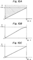
- Fig. 10A shows the case where NRMS not saturated until the quantization step size reaches its maximum, that is, (b) = QS_MAX = 31. Strictly speaking, even when the quantization step size reaches its maximum, saturation may not occur. However, for convenience, saturation is considered to occur at QS = QS_MAX. Fig. 10B shows the curve on which NRMS is generally located. For simplicity, the NRMS curve is approximated as a straight line curve, as shown in Fig. 10C, which passes through the origin (QS = 0, NRMS = 0) and the point (QS = 31, NRMS = (a)).
- Fig. 11A shows the case where NRMS is completely saturated before the quantization step size reaches its maximum, that is, (b) < QS_MAX. For a quantization step size QS in the range (b) to QS_MAX, NRMS = (a). Fig. 11B shows the curve on which NRMS is generally located. For simplicity, the NRMS curve is approximated as a polygonal curve comprising a straight line curve which passes through the origin (QS = 0, NRMS = 0) and the point (QS = (b), NRMS = (a)), followed by a constant portion ((b) < QS <= 31, NRMS = (a)).
- The approximations of Fig. 10C and 11C both include the point (QS = 31, NRMS = (a)).
- The quantization noise curve is estimated as follows.
- First, the saturation quantization step size (b) is predicted. If (b) > QS_MAX, then (b) is limited to QS_MAX = 31.
- Next, the saturation NRMS (a) at QS = QS_MAX is predicted.
- In the range where QS < (b), the quantization noise curve is approximated by a straight line connecting the origin (QS = 0, NRMS = 0) and the point (QS = (b), NRMS = (a)). If (b) = QS_MAX, there is no need to continue.
- If (b) < QS_MAX, then in the range where QS > (b), the quantization noise curve is approximated by a constant (NRMS = (a)).
- Thus, to approximate the quantization noise curve in
MPEG 2, only the saturation NRMS (a) and the saturation quantization step size (b) are needed. - The signal to noise ratio (SNR) is defined as follows:

- A procedure for estimating the saturation NRMS (a) at the maximum quantization step size QS_MAX will now be described. Generally, the procedure is to approximately calculate the portion of each coefficient in a block which will be lost (omitted) by quantization, to sum the lost portions in the block and to multiply the sum by a constant found from, for example, statistical observation of encoding sequences. The multiplied sum is the prediction of the saturation NRMS (a).
- For an intra-macro block, quantization is approximated as follows, from equations (4) and (5):

The portion of each coefficient in an intra-macro block which will be lost by quantization when QS = QS_MAX = 31 is approximated as follows:

where dc = ac(0,0) and it is assumed that Q_dc = 8. During encoding, it is possible to accommodate Q_dc selected from (4, 2, 1). The sum of the coefficient portions lost during quantization of an intra-macro block is defined as follows:
The multiplier constant should be obtained by statistics of the relationship between P1I and NRMS for a source image being encoded. For an MPEG test sequence, the intra-macro block constant is as follows:
For an intra-macro block, the saturation NRMS is predicted from (a) = cI x P1I. - For a non-intra-macro block, quantization is approximated as follows, from equations (6) and (7):

The portion of each coefficient in a non-intra-macro block which will be lost by quantization when QS = QS_MAX = 31 is approximated as follows:
The sum of the coefficient portions lost during quantization of a non-intra-macro block is defined as follows:
The multiplier constant should be obtained by statistics of the relationship between P1N and NRMS for a source image being encoded. For an MPEG test sequence, the non-intra-macro block constant is as follows:
For a non-intra-macro block, the saturation NRMS is predicted from (a) = cN x P1N. - A procedure for estimating the saturation quantization step size (b) will now be described. Generally, the procedure is to find the minimum quantization step size which results in the quantized AC coefficients for a block having values of zero, and to use this minimum quantization step size as the prediction of the saturation quantization step size.
- For an intra-macro block AC coefficient ac(i,j), the minimum quantization step size MIN_QSI(i,j) which results in the quantized AC coefficient QAC(i,j) having a value of zero is found from the following, based on equations (4) and (5):

The quantized coefficient QAC(i,j) will be zero when:
Rearranging terms,
The minimum integer quantization step size which satisfies equation (27) is
Similarly, the minimum integer quantization step size which satisfies equation (27) when ac(i,j) < 0 is
When ac(i,j) = 0, the quantization result is always equal to 0. However, since the possible quantization step size range is 1 to 31, the minimum integer quantization step size is 1, MINO_QSI(i,j) = 1. Summarizing, the minimum quantization step size MIN_QSI is found from
For all of the AC coefficients in an intra-macro block, the minimum quantization step size P2I at which all quantized AC coefficients in the block have a value of zero is
For an intra-macro block, the saturation quantization step size is predicted from (b) = P2I. - For a non-intra-macro block, in a manner similar to the intra-macro block, the above-described prediction procedure is applied to equations (6) and (7) to obtain the minimum quantization step size P2N at which all quantized coefficients in the block have a value of zero:

For a non-intra-macro block, the saturation quantization step size is predicted from (b) = P2N. - Operation of the
noise estimating circuit 15 shown in Fig. 4 will now be described. - The
noise estimating circuit 15 comprisesinput terminal 50,switch 54, saturationnoise estimating circuits multipliers size estimating circuits curve predicting circuit 55 andoutput terminal 56. - Blocks of coefficient data are supplied from
DCT circuit 1 of Fig. 2 to inputterminal 50 of Fig. 4, which supplies the blocks to switch 54.Switch 54 is operative in accordance with a control signal (not shown) to supply intra-macro blocks to terminal 54A and to supply non-intra macro blocks to terminal 54B. - Saturation
noise estimating circuit 51A and saturation quantization stepsize estimating circuit 53A are coupled to switch terminal 54A, and are adapted to receive intra-macro blocks therefrom. Thecircuits - The saturation
noise estimating circuit 51A functions to calculate the value P1I as described above, and to supply the value P1I tomultiplier 52A, which is adapted to multiply the value P1I by an intra-macro block constant cI, as described above, to produce a predicted saturation NRMS (a), and to supply the predicted value (a) to quantization noisecurve predicting circuit 55. - The saturation quantization step
size estimating circuit 53A functions to calculate the value P2I as described above, and to supply the value P2I as a predicted saturation quantization step size (b) to quantization noisecurve predicting circuit 55. - Saturation
noise estimating circuit 51B and saturation quantization stepsize estimating circuit 53B are coupled to switch terminal 54B, and are adapted to receive non-intra-macro blocks therefrom. Thecircuits - The saturation
noise estimating circuit 51B functions to calculate the value P1N as described above, and to supply the value P1N tomultiplier 52B, which is adapted to multiply the value P1N by an intra-macro block constant cN, as described above, to produce a predicted saturation NRMS (a), and to supply the predicted value (a) to quantization noisecurve predicting circuit 55. - The saturation quantization step
size estimating circuit 53B functions to calculate the value P2N as described above, and to supply the value P2N as a predicted saturation quantization step size (b) to quantization noisecurve predicting circuit 55. - The quantization noise
curve predicting circuit 55 functions to estimate a quantization noise curve in accordance with the procedure described above, and to supply the result tooutput terminal 56. - Operation of the
quantization control circuit 8 shown in Fig. 5 will now be described. - The estimated quantization noise curve is supplied from the
noise estimating circuit 15, shown in Figs. 2 and 4, to inputterminal 60 of thequantization control circuit 8 shown in Fig. 5 which supplies the estimated curve to first quantizationstep size circuit 66. A minimum NRMS value (A) is supplied to input terminal 62 and thence to first quantizationstep size circuit 66. The value (A) is obtained from a desired SNR and equation (15). - The first quantization
step size circuit 66 uses the predicted noise curve and the specified minimum NRMS value (A) to generate a first quantization step size QS_N and supplies the step size QS_N tocomparator 70. - Generation of the step size QS_N will be explained with reference to Figs. 12A-12D. First, the
circuit 66 determines whether the minimum NRMS value (A) is less than the saturation NRMS value (a). If not, that is, (A) ≧ (a), as shown in Figs. 12A and 12B, the step size QS_N is set to QS_MAX = 31. Actually, in the case of Fig. 12B, the step size QS_N may be selected anywhere in the range (b) to QS_MAX. - When (A) < (a), then QS_N is set to (A/a) x (b). If (b) = QS_MAX, as shown in Fig. 12C, then QS_N is set to (A/a) x QS_MAX. If (b) < QS_MAX, as shown in Fig. 12D, then QS_N is set to (A/a) x (b). In either of these cases, if rounding is required, QS_N is rounded up to the nearest integer.
- A buffer occupancy value (B) is supplied from buffer
occupancy detecting circuit 17 of Fig. 2 or from bufferoccupancy estimating circuit 17A of Fig. 3 to inputterminal 64 of thequantization control circuit 8 shown in Fig. 5. The buffer occupancy (B) may be, for example, simply the percent of buffer capacity occupied by encoded data awaiting transmission, that is, (B) = D/Y, where D is the amount of encoded data awaiting transmission and Y is the capacity of the buffer. Theinput terminal 64 supplies the buffer occupancy to second quantizationstep size circuit 68. - The second quantization
step size circuit 68 uses the buffer occupancy (B) to generate a second quantization step size QS_B and supplies the step size QS_B tocomparator 70. For example, the step size QS_B may be the product of the buffer occupancy and the maximum quantization step size, QS_B = (B) x (QS_MAX). Several methods are set forth in the MPEG Test Models for determining QS_B. -
Comparator 70 is operative to receive the first and second quantization step sizes QS_N, QS_B, to select the larger for use in actual quantization of a coefficient data block, and to supply the selected step size tooutput terminal 72. - Thus, the
quantization control circuit 8 maximizes the value of the SNR of the video image and prevents the buffer memory from overflowing. Since the selected quantization step size is always at least QS_B, an overflow never occurs. - When a coefficient block representing a lot of information is followed by a coefficient block representing little information, reconstructed image quality is improved by limiting a maximum value of the SNR of the block representing little information. Such limiting corresponds to allocating extra buffer space to the block representing a lot of information. That is, perceived image quality is thought to be improved more by reducing quantization noise in the block representing a lot of information than by reducing quantization noise in the block representing little information.
- If encoding can be performed without considering the buffer occupancy, then QS_N becomes the selected quantization step size, and the SNR of the image becomes generally constant.
- According to the present embodiment, since the quantization noise can be estimated, the quantization step size can be selected together with the buffer occupancy in accordance with the SNR. That is, for example, the quantization can be performed to make the SNR substantially constant. In case of using the same code rate as in the prior art, therefore, a reconstructed picture is stable and a higher quality is obtained.
- With the quantization noise estimating method according to the present embodiment. since the quantization noise can be estimated before the quantization is actually performed, the noise estimating circuit can be easily constructed and the optimum quantization step size can be easily selected.
- In summary, therefore, embodiments of the present invention provide an encoding apparatus and method which avoid the aforementioned disadvantages of the prior art, in which a quantization step size is set in consideration of picture quality; and/or a quantization step size control method and apparatus which selects a quantization step size in accordance with noise introduced by the quantization.
sign(ARG)
If ARG is a positive number, sign(ARG) = 1.
If ARG is zero, sign(ARC) = 0.
If ARG is a negative number, sign(ARG) = -1.
Claims (19)
- A quantization control apparatus comprising:
quantization noise curve estimating means for estimating a quantization noise curve relating quantization noise to quantization step size for a block of image data; and
selecting means for selecting an actual quantization step size in accordance with the estimated quantization noise curve. - The apparatus of claim 1, wherein said quantization noise curve estimating means includes
means for predicting a saturation noise value;
means for predicting a saturation quantization step size corresponding to the saturated noise value; and
means for predicting said estimated quantization noise curve in accordance with said saturation noise value and said saturation quantization step size. - The apparatus of claim 2, wherein said means for predicting is operative to predict said estimated quantization noise curve as a straight line when said saturation quantization step size is a maximum quantization step size, and to predict said estimated quantization noise curve as a polygonal line when said saturation quantization step size is less than said maximum quantization step size.
- The apparatus of claim 2, wherein said means for predicting a saturation noise value is operative to approximately calculate the portions of said block of image data which will be lost by quantization, to sum the lost portions in said block of image data and to multiply the sum by a constant.
- The apparatus of claim 2, wherein said means for predicting a saturation quantization step size is operative to find a minimum quantization step size which results in quantized image data for said block of image data having values of zero.
- The apparatus of claim 1, wherein said selecting means is operative to select said actual quantization step size also in accordance with a buffer occupancy of a buffer which stores quantized image data.
- The apparatus of claim 6, wherein said selecting means includes
first means for generating a first quantization step size in accordance with said estimated quantization noise curve;
second means for generating a second quantization step size in accordance with said buffer occupancy; and
third means for selecting a larger of said first and second quantization step sizes as said actual quantization step size. - The apparatus of claim 7, wherein said first means is operative to generate said first quantization step size also in accordance with a specified noise.
- The apparatus of claim 8, wherein said first means is operative to generate said first quantization step size as a maximum quantization step size when A ≧ a, and to generate said first quantization step size as (A/a) x (b) when A < a, where
A is said specified noise,
a is a saturation noise value, and
b is a saturation quantization step size. - A quantization control method comprising the steps of:
estimating a quantization noise curve relating quantization noise to quantization step size for a block of image data; and
selecting an actual quantization step size in accordance with the estimated quantization noise curve. - The method of claim 10, wherein said step of estimating includes
predicting a saturation noise value;
predicting a saturation quantization step size corresponding to the saturated noise value; and
predicting said estimated quantization noise curve in accordance with said saturation noise value and said saturation quantization step size. - The method of claim 11, wherein said step of predicting said estimated quantization noise curve predicts said estimated quantization noise curve as a straight line when said saturation quantization step size is a maximum quantization step size, and predicts said estimated quantization noise curve as a polygonal line when said saturation quantization step size is less than said maximum quantization step size.
- The method of claim 11, wherein said step of predicting said saturation noise value includes approximately calculating the portions of said block of image data which will be lost by quantization, summing the lost portions in said block of image data and multiplying the sum by a constant.
- The method of claim 11, wherein said step of predicting a saturation quantization step size includes finding a minimum quantization step size which results in quantized image data for said block of image data having values of zero.
- The method of claim 10, wherein said step of selecting selects said actual quantization step size also in accordance with a buffer occupancy of a buffer which stores quantized image data.
- The method of claim 15, wherein said step of selecting includes
generating a first quantization step size in accordance with said estimated quantization noise curve;
generating a second quantization step size in accordance with said buffer occupancy; and
selecting a larger of said first and second quantization step sizes as said actual quantization step size. - The method of claim 16, wherein said step of generating a first quantization step size generates said first quantization step size also in accordance with a specified noise.
- The method of claim 17, wherein said step of generating a first quantization step size includes generating said first quantization step size as a maximum quantization step size when A ≧ a, and generating said first quantization step size as (A/a) x (b) when A < a, where
A is said specified noise,
a is a saturation noise value, and
b is a saturation quantization step size. - An encoding apparatus comprising:
quantization noise curve estimating means for estimating a quantization noise curve relating quantization noise to quantization step size for a block of image data;
selecting means for selecting an actual quantization step size in accordance with the estimated quantization noise curve; and
quantizing means for quantizing said block of image data using said actual quantization step size.
Applications Claiming Priority (3)
| Application Number | Priority Date | Filing Date | Title |
|---|---|---|---|
| JP8408894 | 1994-03-30 | ||
| JP84088/94 | 1994-03-30 | ||
| JP8408894 | 1994-03-30 |
Publications (3)
| Publication Number | Publication Date |
|---|---|
| EP0680221A2 true EP0680221A2 (en) | 1995-11-02 |
| EP0680221A3 EP0680221A3 (en) | 1996-11-27 |
| EP0680221B1 EP0680221B1 (en) | 2001-06-13 |
Family
ID=13820756
Family Applications (1)
| Application Number | Title | Priority Date | Filing Date |
|---|---|---|---|
| EP95302153A Expired - Lifetime EP0680221B1 (en) | 1994-03-30 | 1995-03-30 | Quantizing image data in image compression |
Country Status (5)
| Country | Link |
|---|---|
| US (2) | US5654760A (en) |
| EP (1) | EP0680221B1 (en) |
| KR (1) | KR950035434A (en) |
| CA (1) | CA2145834A1 (en) |
| DE (1) | DE69521238T2 (en) |
Cited By (6)
| Publication number | Priority date | Publication date | Assignee | Title |
|---|---|---|---|---|
| DE19618117C1 (en) * | 1996-05-06 | 1997-10-02 | Siemens Ag | Method for quantization and method for inverse quantization of transformation coding coefficients of a video data storm |
| WO1997039584A1 (en) * | 1996-04-12 | 1997-10-23 | Imedia Corporation | Video transcoder |
| EP0808069A2 (en) * | 1996-05-14 | 1997-11-19 | Daewoo Electronics Co., Ltd | A Quantizer for video signal encoding system |
| WO2000065842A1 (en) | 1999-04-23 | 2000-11-02 | Sony Corporation | Image encoder and its method |
| FR2875076A1 (en) * | 2004-09-07 | 2006-03-10 | Canon Kk | Digital image signal encoding method for use in e.g. digital camera, involves determining encoding mode when level of occupancy is above preset threshold, and encoding sample based on determined encoding mode |
| US7936938B2 (en) | 2004-09-07 | 2011-05-03 | Canon Kabushiki Kaisha | Methods and devices for encoding a digital image signal and associated decoding methods and devices |
Families Citing this family (65)
| Publication number | Priority date | Publication date | Assignee | Title |
|---|---|---|---|---|
| US6084908A (en) * | 1995-10-25 | 2000-07-04 | Sarnoff Corporation | Apparatus and method for quadtree based variable block size motion estimation |
| US5686963A (en) * | 1995-12-26 | 1997-11-11 | C-Cube Microsystems | Method for performing rate control in a video encoder which provides a bit budget for each frame while employing virtual buffers and virtual buffer verifiers |
| KR970057947A (en) * | 1995-12-28 | 1997-07-31 | 배순훈 | Type Determination and Buffer Control Unit in Image Encoder |
| FR2748623B1 (en) * | 1996-05-09 | 1998-11-27 | Thomson Multimedia Sa | VARIABLE FLOW ENCODER |
| DE69709835T2 (en) * | 1996-05-28 | 2002-08-22 | Matsushita Electric Ind Co Ltd | DEVICE FOR PREDICTING AND DECODING |
| US5809178A (en) * | 1996-06-11 | 1998-09-15 | Apple Computer, Inc. | Elimination of visible quantizing artifacts in a digital image utilizing a critical noise/quantizing factor |
| US5760836A (en) * | 1996-08-22 | 1998-06-02 | International Business Machines Corporation | FIFO feedback and control for digital video encoder |
| JP3116994B2 (en) * | 1996-08-29 | 2000-12-11 | 富士ゼロックス株式会社 | Image quality prediction apparatus and method and image quality control apparatus and method |
| JP3623056B2 (en) * | 1996-09-10 | 2005-02-23 | ソニー株式会社 | Video compression device |
| US6108027A (en) * | 1996-12-17 | 2000-08-22 | Netergy Networks, Inc. | Progressive still frame mode |
| FI107496B (en) * | 1997-07-18 | 2001-08-15 | Nokia Mobile Phones Ltd | Image Compressor Call |
| US6961378B1 (en) | 1998-11-05 | 2005-11-01 | International Business Machines Corporation | On-chip dynamic buffer level indicators for digital video encoder |
| KR100313217B1 (en) * | 1998-12-23 | 2001-12-28 | 서평원 | Pipeline DCT device |
| US7082162B2 (en) * | 1999-04-17 | 2006-07-25 | Pts Corporation | Segment-based encoding system including segment-specific metadata |
| US6600786B1 (en) | 1999-04-17 | 2003-07-29 | Pulsent Corporation | Method and apparatus for efficient video processing |
| US7050503B2 (en) * | 1999-04-17 | 2006-05-23 | Pts Corporation | Segment-based encoding system using residue coding by basis function coefficients |
| US7085319B2 (en) * | 1999-04-17 | 2006-08-01 | Pts Corporation | Segment-based encoding system using segment hierarchies |
| KR20020047031A (en) * | 1999-04-17 | 2002-06-21 | 펄센트 코포레이션 | Method and apparatus for efficient video processing |
| JP2001218210A (en) * | 2000-02-02 | 2001-08-10 | Sony Corp | Noise detection method, noise detector, image data processing unit, and recording medium |
| JP4297235B2 (en) * | 2000-03-17 | 2009-07-15 | パナソニック株式会社 | Signal recording apparatus, signal recording method, signal reproducing apparatus, signal reproducing method, and recording medium |
| US7082166B2 (en) * | 2000-04-17 | 2006-07-25 | Pts Corporation | Decoder for decoding segment-based encoding of video data using segmentation performed at a decoder |
| US6888894B2 (en) * | 2000-04-17 | 2005-05-03 | Pts Corporation | Segmenting encoding system with image segmentation performed at a decoder and encoding scheme for generating encoded data relying on decoder segmentation |
| FR2823943A1 (en) * | 2001-04-24 | 2002-10-25 | Koninkl Philips Electronics Nv | MPEG coded digital video signal noise detection/noise reduction transcoding process having current image detected/coding search carried out finding reference coded macroblocks/noisy macroblock separated out. |
| JP2003032677A (en) * | 2001-07-18 | 2003-01-31 | Hitachi Ltd | Compressive coder for moving image |
| US7027982B2 (en) | 2001-12-14 | 2006-04-11 | Microsoft Corporation | Quality and rate control strategy for digital audio |
| US7418037B1 (en) * | 2002-07-15 | 2008-08-26 | Apple Inc. | Method of performing rate control for a compression system |
| US7769084B1 (en) | 2002-07-15 | 2010-08-03 | Apple Inc. | Method for implementing a quantizer in a multimedia compression and encoding system |
| US7804897B1 (en) | 2002-12-16 | 2010-09-28 | Apple Inc. | Method for implementing an improved quantizer in a multimedia compression and encoding system |
| US7940843B1 (en) * | 2002-12-16 | 2011-05-10 | Apple Inc. | Method of implementing improved rate control for a multimedia compression and encoding system |
| KR100584552B1 (en) * | 2003-01-14 | 2006-05-30 | 삼성전자주식회사 | Method for encoding and decoding video and apparatus thereof |
| NO318973B1 (en) * | 2003-07-01 | 2005-05-30 | Tandberg Telecom As | Noise Reduction Procedure |
| US7738554B2 (en) | 2003-07-18 | 2010-06-15 | Microsoft Corporation | DC coefficient signaling at small quantization step sizes |
| US7343291B2 (en) * | 2003-07-18 | 2008-03-11 | Microsoft Corporation | Multi-pass variable bitrate media encoding |
| US7383180B2 (en) * | 2003-07-18 | 2008-06-03 | Microsoft Corporation | Constant bitrate media encoding techniques |
| US7602851B2 (en) * | 2003-07-18 | 2009-10-13 | Microsoft Corporation | Intelligent differential quantization of video coding |
| US7580584B2 (en) * | 2003-07-18 | 2009-08-25 | Microsoft Corporation | Adaptive multiple quantization |
| US10554985B2 (en) | 2003-07-18 | 2020-02-04 | Microsoft Technology Licensing, Llc | DC coefficient signaling at small quantization step sizes |
| US8218624B2 (en) * | 2003-07-18 | 2012-07-10 | Microsoft Corporation | Fractional quantization step sizes for high bit rates |
| US7418148B2 (en) * | 2003-09-29 | 2008-08-26 | Casio Computer Co., Ltd. | Image compression method and image compression device |
| US7801383B2 (en) | 2004-05-15 | 2010-09-21 | Microsoft Corporation | Embedded scalar quantizers with arbitrary dead-zone ratios |
| KR100708118B1 (en) * | 2005-01-07 | 2007-04-16 | 삼성전자주식회사 | Apparatus for encoding and decoding video based on a plurality of modified multiplication factor table and method thereof, and recording medium storing a program for implementing the method |
| US8422546B2 (en) | 2005-05-25 | 2013-04-16 | Microsoft Corporation | Adaptive video encoding using a perceptual model |
| US7995649B2 (en) | 2006-04-07 | 2011-08-09 | Microsoft Corporation | Quantization adjustment based on texture level |
| US8130828B2 (en) | 2006-04-07 | 2012-03-06 | Microsoft Corporation | Adjusting quantization to preserve non-zero AC coefficients |
| US8503536B2 (en) | 2006-04-07 | 2013-08-06 | Microsoft Corporation | Quantization adjustments for DC shift artifacts |
| US8059721B2 (en) | 2006-04-07 | 2011-11-15 | Microsoft Corporation | Estimating sample-domain distortion in the transform domain with rounding compensation |
| US7974340B2 (en) | 2006-04-07 | 2011-07-05 | Microsoft Corporation | Adaptive B-picture quantization control |
| US8711925B2 (en) | 2006-05-05 | 2014-04-29 | Microsoft Corporation | Flexible quantization |
| US8238424B2 (en) | 2007-02-09 | 2012-08-07 | Microsoft Corporation | Complexity-based adaptive preprocessing for multiple-pass video compression |
| US8498335B2 (en) | 2007-03-26 | 2013-07-30 | Microsoft Corporation | Adaptive deadzone size adjustment in quantization |
| US8243797B2 (en) | 2007-03-30 | 2012-08-14 | Microsoft Corporation | Regions of interest for quality adjustments |
| US8442337B2 (en) | 2007-04-18 | 2013-05-14 | Microsoft Corporation | Encoding adjustments for animation content |
| JP2008283560A (en) * | 2007-05-11 | 2008-11-20 | Canon Inc | Information processing apparatus and method thereof |
| US8331438B2 (en) | 2007-06-05 | 2012-12-11 | Microsoft Corporation | Adaptive selection of picture-level quantization parameters for predicted video pictures |
| US8934539B2 (en) * | 2007-12-03 | 2015-01-13 | Nvidia Corporation | Vector processor acceleration for media quantization |
| US8687875B2 (en) * | 2007-12-03 | 2014-04-01 | Nvidia Corporation | Comparator based acceleration for media quantization |
| US8189933B2 (en) | 2008-03-31 | 2012-05-29 | Microsoft Corporation | Classifying and controlling encoding quality for textured, dark smooth and smooth video content |
| US8325800B2 (en) | 2008-05-07 | 2012-12-04 | Microsoft Corporation | Encoding streaming media as a high bit rate layer, a low bit rate layer, and one or more intermediate bit rate layers |
| US8379851B2 (en) | 2008-05-12 | 2013-02-19 | Microsoft Corporation | Optimized client side rate control and indexed file layout for streaming media |
| US7925774B2 (en) | 2008-05-30 | 2011-04-12 | Microsoft Corporation | Media streaming using an index file |
| US8897359B2 (en) | 2008-06-03 | 2014-11-25 | Microsoft Corporation | Adaptive quantization for enhancement layer video coding |
| US8265140B2 (en) | 2008-09-30 | 2012-09-11 | Microsoft Corporation | Fine-grained client-side control of scalable media delivery |
| GB2501115B (en) | 2012-04-13 | 2015-02-18 | Canon Kk | Methods for segmenting and encoding an image, and corresponding devices |
| KR102000517B1 (en) * | 2012-11-12 | 2019-07-16 | 삼성전자주식회사 | Signal generator and the signal transfer system to quantize the signal for channel retention of wireless communication |
| US11082717B2 (en) * | 2017-07-05 | 2021-08-03 | Onesubsea Ip Uk Limited | Data compression for communication in subsea oil and gas systems |
Citations (6)
| Publication number | Priority date | Publication date | Assignee | Title |
|---|---|---|---|---|
| US4774574A (en) * | 1987-06-02 | 1988-09-27 | Eastman Kodak Company | Adaptive block transform image coding method and apparatus |
| US4776030A (en) * | 1986-03-28 | 1988-10-04 | Gte Laboratories Incorporated | Block quantizer for transform coding |
| EP0490539A2 (en) * | 1990-12-11 | 1992-06-17 | AT&T Corp. | Adaptive non-linear quantizer |
| EP0493136A2 (en) * | 1990-12-28 | 1992-07-01 | Victor Company Of Japan, Ltd. | Interframe-coded output data amount control system |
| EP0509576A2 (en) * | 1991-04-18 | 1992-10-21 | Ampex Systems Corporation | Method and apparatus for determining a quantizing factor for processes involving multiple compression/decompression of data |
| EP0675653A1 (en) * | 1994-03-30 | 1995-10-04 | STMicroelectronics S.A. | Quantization circuit |
Family Cites Families (9)
| Publication number | Priority date | Publication date | Assignee | Title |
|---|---|---|---|---|
| US5542008A (en) * | 1990-02-28 | 1996-07-30 | Victor Company Of Japan, Ltd. | Method of and apparatus for compressing image representing signals |
| KR930000033B1 (en) * | 1990-10-18 | 1993-01-06 | 삼성전자 주식회사 | Quantification wide adjusting circuits using edge detection |
| US5144423A (en) * | 1990-12-11 | 1992-09-01 | At&T Bell Laboratories | Hdtv encoder with forward estimation and constant rate motion vectors |
| JP3093458B2 (en) * | 1992-07-23 | 2000-10-03 | 株式会社東芝 | Variable rate codec / decoder |
| JP3106749B2 (en) * | 1992-12-10 | 2000-11-06 | ソニー株式会社 | Adaptive dynamic range coding device |
| KR940020832A (en) * | 1993-02-25 | 1994-09-16 | 김주용 | Adaptive Quantization Method of High-definition Television and System Coder Using the Same |
| KR970011859B1 (en) * | 1993-04-15 | 1997-07-18 | 삼성전자 주식회사 | Encoding method and device for using fuzzy control |
| EP0675663B1 (en) * | 1994-03-31 | 2000-05-17 | Siemens Aktiengesellschaft | Method of connection set-up between several networks of a mobile radio system |
| JPH0888848A (en) * | 1994-09-12 | 1996-04-02 | Daewoo Electron Co Ltd | Quantized pattern code book configuration method |
-
1995
- 1995-03-27 US US08/410,721 patent/US5654760A/en not_active Expired - Fee Related
- 1995-03-29 CA CA002145834A patent/CA2145834A1/en not_active Abandoned
- 1995-03-30 DE DE69521238T patent/DE69521238T2/en not_active Expired - Fee Related
- 1995-03-30 KR KR1019950007681A patent/KR950035434A/en not_active Application Discontinuation
- 1995-03-30 EP EP95302153A patent/EP0680221B1/en not_active Expired - Lifetime
-
1997
- 1997-04-04 US US08/832,788 patent/US5739863A/en not_active Expired - Fee Related
Patent Citations (6)
| Publication number | Priority date | Publication date | Assignee | Title |
|---|---|---|---|---|
| US4776030A (en) * | 1986-03-28 | 1988-10-04 | Gte Laboratories Incorporated | Block quantizer for transform coding |
| US4774574A (en) * | 1987-06-02 | 1988-09-27 | Eastman Kodak Company | Adaptive block transform image coding method and apparatus |
| EP0490539A2 (en) * | 1990-12-11 | 1992-06-17 | AT&T Corp. | Adaptive non-linear quantizer |
| EP0493136A2 (en) * | 1990-12-28 | 1992-07-01 | Victor Company Of Japan, Ltd. | Interframe-coded output data amount control system |
| EP0509576A2 (en) * | 1991-04-18 | 1992-10-21 | Ampex Systems Corporation | Method and apparatus for determining a quantizing factor for processes involving multiple compression/decompression of data |
| EP0675653A1 (en) * | 1994-03-30 | 1995-10-04 | STMicroelectronics S.A. | Quantization circuit |
Cited By (9)
| Publication number | Priority date | Publication date | Assignee | Title |
|---|---|---|---|---|
| WO1997039584A1 (en) * | 1996-04-12 | 1997-10-23 | Imedia Corporation | Video transcoder |
| DE19618117C1 (en) * | 1996-05-06 | 1997-10-02 | Siemens Ag | Method for quantization and method for inverse quantization of transformation coding coefficients of a video data storm |
| EP0808069A2 (en) * | 1996-05-14 | 1997-11-19 | Daewoo Electronics Co., Ltd | A Quantizer for video signal encoding system |
| EP0808069A3 (en) * | 1996-05-14 | 1998-05-06 | Daewoo Electronics Co., Ltd | A Quantizer for video signal encoding system |
| WO2000065842A1 (en) | 1999-04-23 | 2000-11-02 | Sony Corporation | Image encoder and its method |
| EP1091588A1 (en) * | 1999-04-23 | 2001-04-11 | Sony Corporation | Image encoder and its method |
| EP1091588A4 (en) * | 1999-04-23 | 2004-08-11 | Sony Corp | Image encoder and its method |
| FR2875076A1 (en) * | 2004-09-07 | 2006-03-10 | Canon Kk | Digital image signal encoding method for use in e.g. digital camera, involves determining encoding mode when level of occupancy is above preset threshold, and encoding sample based on determined encoding mode |
| US7936938B2 (en) | 2004-09-07 | 2011-05-03 | Canon Kabushiki Kaisha | Methods and devices for encoding a digital image signal and associated decoding methods and devices |
Also Published As
| Publication number | Publication date |
|---|---|
| EP0680221A3 (en) | 1996-11-27 |
| DE69521238D1 (en) | 2001-07-19 |
| US5654760A (en) | 1997-08-05 |
| EP0680221B1 (en) | 2001-06-13 |
| CA2145834A1 (en) | 1995-10-01 |
| DE69521238T2 (en) | 2002-01-10 |
| KR950035434A (en) | 1995-12-30 |
| US5739863A (en) | 1998-04-14 |
Similar Documents
| Publication | Publication Date | Title |
|---|---|---|
| EP0680221B1 (en) | Quantizing image data in image compression | |
| EP0422404B1 (en) | Transform coding using coefficient prediction techniques | |
| EP0519962B1 (en) | Digital image coding using a random scanning of image frames | |
| US6658157B1 (en) | Method and apparatus for converting image information | |
| US5592302A (en) | Coding method for coding pixel blocks and apparatus therefor | |
| US7460597B2 (en) | Encoding apparatus and method | |
| EP0673172B1 (en) | Method and apparatus for preventing repetitive random errors in transform coefficients representing a motion picture signal | |
| US6256413B1 (en) | Image encoding apparatus | |
| US6337879B1 (en) | Video data compression apparatus and method of same | |
| JPH0797753B2 (en) | Encoding output data amount control method | |
| EP0833522A2 (en) | Video signal encoding method and apparatus employing an adaptive quantization technique | |
| JPH0595536A (en) | High efficiency coded signal processor | |
| EP1619900B1 (en) | Bit rate controller | |
| US20040028127A1 (en) | Method and apparatus for reducing computational complexity in video encoders | |
| US5905578A (en) | Coding apparatus | |
| JPH06292019A (en) | Picture data compressor and picture code compressor | |
| JP3978810B2 (en) | Encoding method and encoding apparatus using the same | |
| US7801214B2 (en) | Method and apparatus for controlling encoding rate and quantization scales | |
| JP2768260B2 (en) | Image coding control method | |
| EP0680218A2 (en) | Image signal decoding apparatus having an encoding error compensation | |
| JP2843024B2 (en) | Method and apparatus for selecting transform coefficient of transform coding system | |
| EP1589762A1 (en) | Image compression with reduced block artefacts | |
| KR0148226B1 (en) | Code method and apparatus of quantizer | |
| JP3337699B2 (en) | Image processing apparatus and method | |
| JPH0818952A (en) | Image signal coder |
Legal Events
| Date | Code | Title | Description |
|---|---|---|---|
| PUAI | Public reference made under article 153(3) epc to a published international application that has entered the european phase |
Free format text: ORIGINAL CODE: 0009012 |
|
| AK | Designated contracting states |
Kind code of ref document: A2 Designated state(s): DE FR GB NL |
|
| PUAL | Search report despatched |
Free format text: ORIGINAL CODE: 0009013 |
|
| AK | Designated contracting states |
Kind code of ref document: A3 Designated state(s): DE FR GB NL |
|
| 17P | Request for examination filed |
Effective date: 19970411 |
|
| 17Q | First examination report despatched |
Effective date: 19990326 |
|
| GRAG | Despatch of communication of intention to grant |
Free format text: ORIGINAL CODE: EPIDOS AGRA |
|
| GRAG | Despatch of communication of intention to grant |
Free format text: ORIGINAL CODE: EPIDOS AGRA |
|
| GRAH | Despatch of communication of intention to grant a patent |
Free format text: ORIGINAL CODE: EPIDOS IGRA |
|
| GRAH | Despatch of communication of intention to grant a patent |
Free format text: ORIGINAL CODE: EPIDOS IGRA |
|
| GRAA | (expected) grant |
Free format text: ORIGINAL CODE: 0009210 |
|
| AK | Designated contracting states |
Kind code of ref document: B1 Designated state(s): DE FR GB NL |
|
| REF | Corresponds to: |
Ref document number: 69521238 Country of ref document: DE Date of ref document: 20010719 |
|
| ET | Fr: translation filed | ||
| REG | Reference to a national code |
Ref country code: GB Ref legal event code: IF02 |
|
| PGFP | Annual fee paid to national office [announced via postgrant information from national office to epo] |
Ref country code: FR Payment date: 20020312 Year of fee payment: 8 |
|
| PGFP | Annual fee paid to national office [announced via postgrant information from national office to epo] |
Ref country code: NL Payment date: 20020328 Year of fee payment: 8 |
|
| PG25 | Lapsed in a contracting state [announced via postgrant information from national office to epo] |
Ref country code: GB Free format text: LAPSE BECAUSE OF NON-PAYMENT OF DUE FEES Effective date: 20020330 |
|
| PLBE | No opposition filed within time limit |
Free format text: ORIGINAL CODE: 0009261 |
|
| STAA | Information on the status of an ep patent application or granted ep patent |
Free format text: STATUS: NO OPPOSITION FILED WITHIN TIME LIMIT |
|
| 26N | No opposition filed | ||
| PG25 | Lapsed in a contracting state [announced via postgrant information from national office to epo] |
Ref country code: DE Free format text: LAPSE BECAUSE OF NON-PAYMENT OF DUE FEES Effective date: 20021001 |
|
| GBPC | Gb: european patent ceased through non-payment of renewal fee |
Effective date: 20020330 |
|
| PG25 | Lapsed in a contracting state [announced via postgrant information from national office to epo] |
Ref country code: NL Free format text: LAPSE BECAUSE OF NON-PAYMENT OF DUE FEES Effective date: 20031001 |
|
| PG25 | Lapsed in a contracting state [announced via postgrant information from national office to epo] |
Ref country code: FR Free format text: LAPSE BECAUSE OF NON-PAYMENT OF DUE FEES Effective date: 20031127 |
|
| NLV4 | Nl: lapsed or anulled due to non-payment of the annual fee |
Effective date: 20031001 |
|
| REG | Reference to a national code |
Ref country code: FR Ref legal event code: ST |