EP0683282A1 - A Light weight wall structure for use in buildings - Google Patents
A Light weight wall structure for use in buildings Download PDFInfo
- Publication number
- EP0683282A1 EP0683282A1 EP94303645A EP94303645A EP0683282A1 EP 0683282 A1 EP0683282 A1 EP 0683282A1 EP 94303645 A EP94303645 A EP 94303645A EP 94303645 A EP94303645 A EP 94303645A EP 0683282 A1 EP0683282 A1 EP 0683282A1
- Authority
- EP
- European Patent Office
- Prior art keywords
- panel
- sub
- wall
- panels
- post
- Prior art date
- Legal status (The legal status is an assumption and is not a legal conclusion. Google has not performed a legal analysis and makes no representation as to the accuracy of the status listed.)
- Withdrawn
Links
Images


Classifications
-
- E—FIXED CONSTRUCTIONS
- E04—BUILDING
- E04B—GENERAL BUILDING CONSTRUCTIONS; WALLS, e.g. PARTITIONS; ROOFS; FLOORS; CEILINGS; INSULATION OR OTHER PROTECTION OF BUILDINGS
- E04B2/00—Walls, e.g. partitions, for buildings; Wall construction with regard to insulation; Connections specially adapted to walls
- E04B2/84—Walls made by casting, pouring, or tamping in situ
- E04B2/842—Walls made by casting, pouring, or tamping in situ by projecting or otherwise applying hardenable masses to the exterior of a form leaf
-
- E—FIXED CONSTRUCTIONS
- E04—BUILDING
- E04F—FINISHING WORK ON BUILDINGS, e.g. STAIRS, FLOORS
- E04F13/00—Coverings or linings, e.g. for walls or ceilings
- E04F13/02—Coverings or linings, e.g. for walls or ceilings of plastic materials hardening after applying, e.g. plaster
- E04F13/04—Bases for plaster
Definitions
- This invention relates to a light weight wall structure for use in buildings and, more particularly, to such a structure characterized by improved structural strength and permitting quick construction.
- Wall structures using light weight steel-frames are normally faced with plaster board or concrete slabs laid on trusses of light steel frames to form a surface on a partition wall. These walls are defective in that they are lacking in strength, possess little aesthetic appeal, poor endurance, and in the event of earthquakes or other vibrations create pressure on the structures which can not be dispersed thereby creating wall cracks which will appear irregular. In the event of excessive vibration, the wall face could become severely cracked and dangerous. The wall may collapse. It is also expensive to batch or repair a damaged wall.
- the conventional wall face could easily suffer from cement lifting from the frame or cracking due to impacts by external forces.
- the wall face has suffered damage, not only is its appearance affected but it also requires expensive and time consuming repair. For this reason the part of the well most likely to be hit is often covered in large protection plates to prevent the wall face from being damaged.
- Conventional light weight steel-framed structures usually include I-bar or U-bar steel to form posts in association with a number of beams fixed together to form a frame. Because the posts and beams need to be large in length as well as in thickness due to the requirement of strength, they are not convenient to transport and assemble. Because of restrictions in the method of construction, it is not possible to adopt a round-bar or a square-bar sectional steel which is of greater structural strength, not to mention the use of round or square tube steel. Because of construction complexity, the waste of time and cost, and building load problem, the conventional RC structure is not sufficiently efficient, high strength, low weight for the construction of modern buildings. For this reason the construction of modern buildings avoids the use of conventional RC techniques as possible in order to reduce the weight and difficulty of construction. Builders have even avoided using RC structure partitions in order to prevent elastic pressure from steel girders. It will be appreciated that many attempts to pursue alternatives have been made without success.
- One object of this invention is to provide a light weight framed wall structure with good structural strength and facility for quick construction.
- Another object of this invention is to provide a light steel-framed wall sturcture formed by base board sub-panels with high completeness and without the necessity of establishing a thickness datum for the wall face.
- Still another object of this invention is to provide a light steel-framed wall structure with a quick-assembly light steel frame to improve construction over the conventional RC structure.
- Still another object of this invention is to provide a light steel-framed wall structure that can offer greater resistance to damage.
- FIG. 1 is an elevational view of the present invention.
- FIG. 2 is an assembly view of the wall skeletal, showing the embodiment of wall skeletal composed of base board sub-panels according to the present invention.
- FIG. 3 is a sectional view of built-up posts according to the present invention, showing how said built-up posts adopt three blocks in combination.
- FIG. 4 is a part perspective view of wall skeletal, shoving how built-up posts and top steel frame are nailed together.
- FIG. 5 is a part perspective view of another embodiment of the wall frame, showing built-up posts and top steel frame screwed together.
- FIG. 6 is a part perspective view of another embodiment of the present invention, showing built-up posts adopt plates in connection with the upper section of posts separately.
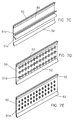
- FIG. 7 is an elevational view of the gusset sub-panels used in the present invention.
- FIG. 7A is an elevational view of the embodiment showing the gusset sub-panels of the present invention including inverted "L" retention sheets.
- FIG. 7B is an elevational view of the embodiment showing the russet sub-panels of the present invention including bevel retention sheets.
- FIG. 7C is an elevational view of the embodiment showing the gusset sub-panels of the present invention including hook retention sheets.
- FIG. 7D is an elevational view of the embodiment showing the gusset sub-panels of the present invention including screw-locked retention sheets.
- FIG. 7E is an elevational view of the embodiment showing the gusset sub-panels of the present invention including burst type bore holes.
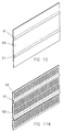
- FIG. 8 is an elevational view of the embodiment showing the gusset sub-panels of the present invention including perpendicular sheets.
- FIG. 9 is a side view of the base boards assembled together with gusset sub-panels according to the present invention.
- FIG. 10 is an elevational view of the base board sub-panels of the present invention.
- FIG. 11A is an elevational view of the embodiment for the base board sub-panels of the present invention including holes to increase retention of slurry.
- FIG. 11B is an elevational view of the embodiment for the base board sub-panels of the present invention including burst holes to increase retention of slurry.
- FIG. 11C is an elevational view of the embodiment for the base board sub-panels of the present invention including screw-locked retention sheets.
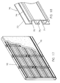
- FIG. 12 is an elevational view of the embodiment, showing extension plates directly formed by bending an edge of the gusset sub-panels.
- FIG. 13 is a partial side view of gusset sub-panels shown in FIG.12 in combination with base board sub-panels.
- FIG. 14 is an elevational view of another structure of gusset sub-panels with extension plates.
- FIG. 15 is an elevational view of the embodiment, showing extension plates located by the side of the base board sub-panels.
- FIG. 16 is an elevational view of the embodiment, showing gusset sub-panels and base board sub-panels with extension plates.
- FIG. 17 is an elevational view of the embodiment, shoving the portion of wall likely to be hit having a protection plate.
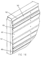
- FIG. 18 is an elevational view of the protection plate of the present invention.
- the light weight steel-framed wall structure comprises a number of gusset sub-panels 50 and base board sub panels attached to a skeletal frame 10.
- a wall face is formed by placing slurry on the sub-panels in an appropriate thickness.
- the skeletal frame 10 comprises built-up posts 11 and adjacent steel poles 33 and 34.
- the built-up post 11 includes an upper post 12a, an intermediate post 14 and a lower post 12b.
- the adjacent steel poles 33 and 34 define the limit of the ends of the wall.
- Built-up posts 11 in association with the upper and lower steel girders (or floors) 31 and 32 may produce a prop and a tie as desired to form an integral solid skeletal wall.
- the built-up posts may include multiple blocks, and the sectional shade of each block, except the threaded portion, can be of any cross sectional shape.
- the best structural strength is obtained by using hollow round tubes or square tubes since they have the advantage of being light weight and strong.
- solid round or square sectioned columns can also give ideal strength.
- said built-up post 11 includes the upper post 12a, the intermediate post 14, the lower post 12b, an upper screw bush 20 and lower screw bush 25.
- the upper post 12b resembles a long column, and includes a plate 13 on one end and a hollow chamber 17 on the other end.
- the upper screw bush 20 resembles a hollow column which fits inside the hollow chamber 17 of said upper post 12a, and has internal thread 22 axially through, the center.
- Said lower post 12b resembles a lone column similar to said upper post 12a, including a plate 19 on one end and a hollow chamber 18 on the other end.
- the lower screw bush 25 resembles a hollow column and fits inside the hollow chamber 17 of said upper post 12a, and further has an internal thread 27 axially through the center.
- the thread is opposite to the thread of the internal thread 22 on said upper screw bush 20 (i.e. one is a left-handed thread while the other is a right-handed thread).
- the intermediate post 14 resembles a lone column, both ends having lone threads 15, 16 of opposite direction for screwing up of respective internal threads 22, 27 of upper and lower screw bushes 20, 25.
- Said built-up post may be constructed quickly into a skeletal partition wall between upper and lower steel girders (or steel plates ) 31 and 32 as shown in FIG.2, and the following construction steps are taken: inking two parallel lines on the upper and lower steel girders (or floor) 31, 32 as guides for the erection of the built-up posts 11 on both sides of the wall; erect steel poles 33, 34 at both ends between the parallel lines to define the ends of the wall; fix the plates 13, 19 of the upper and lower posts 12a and 12b between the parallel lines marked on upper and lower steel girders (or floor) 31, 32; with screws or nails 40 (or steel nails) by means of a power drill or hammer; install the intermediate post 14 by inserting the upper and lower screw bushes 20, 25 into the hollow chambers 17, 18 of the upper and lower posts 12a, 12b respectively.
- the screw bushes 20, 25 are axially slidable in the hollow chambers without being rotatable. Screw up the lone threads 15, 16 of intermediate post 14 into the internal threads 22, 27 of the upper and lower screw bushes 20, 25 respectively to join together the posts 12a, 14 and 12b. Because the spacing between the upper and lower posts is adjustable, it is very convenient for fast installation.
- the intermediate post 14 Upon installation of each built-up post 11, the intermediate post 14 is screwed up. Because the long threads 15, 16 on said intermediate post 14 are of opposite thread directions when the intermediate post 14 is rotated, the upper and lower screw bushes 20, 25 will be pushed outwardly and accordingly the upper post 11 and lower post 12b will be locked apart (or if the intermediate post 14 were turned in the opposite direction to cause said upper and lower posts to be pulled towards each other). The whole structure may thus carry out the function of a prop. It should be noted that, because there are many built-up posts 11 erected between said upper and lower steel girders (or floors) 31, 32, once each intermediate post 14 is screwed up the force sustained by the whole structure must be even. Therefore screwing up must be done in order (i.e. each intermediate post 14 and post 11 should be screwed up progressively so as to ensure that the prop is well screwed up) to ensure the whole structure sustains an even force. A complete built-up steel frame is thus formed.
- a number of beams can then be fastened to the post with self-tapping screws to reinforce the structure.
- the skeletal formed according to the present invention together with base board sub-panels made of alloy plates is adequate for giving ideal strength so that reinforcement by additional beams is not necessary. Since additional reinforeing beams can be omitted and construction procedure is simplified work and assembly is carried out relatively rapidly.
- the integration of built-up post 11 with upper and lower steel girders (or floors 31, 32), except for fixing by screws or nails 40 with plates 13, 19 as shown in FIG. 4, may include the chance of the plate 13 into a stud 45 for screwing up with thread holes 46 on the steel girder 31 as shown in FIG. 5, or other method available for quick assemble to attain an equivalent result.
- the plates may be replaced by a movable assemble of plate member 47 with upper and lower posts 12a, 12b, in which one end has smaller diameter for fitting into the upper and lower posts 12a, 12b and the other end has a plate portion projecting over an end for fixing on steel girders (or floor) 31, 32.
- the upper and lower screw bushes 20, 25 are movable fitted in the hollow chambers 13, 18 of the upper and lower posts 12a, 12b respectively, the upper and lower posts 12a, 12b can be cut as necessary to make them suitable for any uneven ground or ceiling.
- Each member can be made individually for assembly on site to increase production efficiency of components and to lower waste due to work error.
- Upper and lower bushes 20, 25 may be omitted if the dimensions exposed are a little different or if solid tubes are selected for direct tapping.
- the skeletal wall frame according to the present invention can be readily assembled and has advantages such as light weight and high strength, and further it may enable tight integration of overall strength by means of a locked prop to prevent local breakage and therefore to offer firm support to the wall boards of the present invention.
- the aforesaid built-up post 11 may be used as the skeleton of the built-up wall or for other purposes such as a support for the floor or decoration material and for the assembly of scaffolding.
- the gusset sub-panel 50 of the present invention is a long and narrow sheet; the reverse side is flat for attachment with the wall frame while the front surface has a number of retention members 51 for increasing the retention of slurry on the wall surface.
- Two edges of the front surface of the gusset sub-panel so have an extension plate 52 extending outwardly and upward obliquely, the height of the extension plate 52 is greater than the thickness of said base board sub-panel 60 so that the spacing between with front surface of said gusset sub-panel 50 may be set to engage with the edge of said base board sub-panel 60 to enable said two plates to connect together firmly.
- the catchorretention member has a "T” section and a long-bar retention sheet integrally formed with said gusset sub-panel 20.
- said retention member 51 is not limited to a "T-shape", but may be designed as inverted “L” retention member 51a, bevel retention member 51b, or hook retention member 51c as shown in FIG. 7A, 7B, 7C respectively, or other members to increase retention.
- retention members on the gusset sub-panel 50 may also be screwed to the gusset sub-panel.
- a number of "cross" retention sheets 51d maybe screwed onto the surface of the gusset sub-panel 50 as shown in FIG. 7D.
- the surface of said gusset sub-panel 50 may include number of bore holes to form "burst" holes 51e through outward bending of the irregular rim of the holes.
- a number of burst holes 51e can thus be provided as retention members as shown in FIG. 7E.
- the gusset sub-panel 50 also includes a level sheet 53.
- the level sheet 53 may be formed by extending the retention member 51. The height of the top edge of the level sheet is greater than the height of said retention member 51 and is perpendicular to the surface of said gusset sub-panel 50.
- the gusset sub-panel 50 with level sheet 53 may be positioned as required to offer a datum for the thickness of the slurry.
- Said gusset sub-panels 50 and base board sub-panels 60 may be parallel and alternately tied on the skeletal wall frame.
- Each gusset 50 can be fitted next to the base board sub-panel 60 by means of the lateral extension plate so that a number of base board sub-panels 60 can be set alternately between a number of gusset sub-panels 50 and be tied to the skeletal wall frame by means of screws or nails to form a firm wall structure (as shown in FIG. 9).
- the base board sub-panel 60 is formed by metal sheet cut to size. The width and length can be adjusted subject to requirements.
- the base board sub-panel 60 may be bent to form a number of ribs 61 for increasing bend resistance of the base board sub-panel 60.
- said base board sub-panel 60 may include a device for increasing its slurry retention as shown in FIG. 11A.
- the base board 60 has a number of holes 62 for increasing its slurry retention.
- the surface of the base board sub-panel 60 is made with a number of burst holes 63 and outward bending of the holes to form burst holes 63 for retention slurry.
- the surface of the base board sub-panel 60 may be screwed with retention sheet 64 to carry out the above function.
- gusset sub-panel 50 Upon installation of said gusset sub-panel 50 and base board sub-panel slurry may be applied to the wall face. Because gusset sub-panel 50 have level sheets 53, troublesome work of wiring up parallel points according to conventional wall construction can be omitted to reduce work deviation and material waste.
- gusset sub-panel 50 and base board sub-panel 60 of the present invention may further be changed as shown in FIG. 12.
- the extension plate 52 of gusset sub-panel 50 can be formed by upward bending of the edge of the gusset sub-panel 50. It will be much easier to make such a structure because it is only necessary to bend the gusset sub-panel to form the extension plate 52. Referring to FIG. 13, the height of the extension plate 52 is greater than the thickness of said base board 60. Therefore once the gusset sub-panel is locked to the skeletal wall frame, a spacing is defined between a surface of said extension plate 52 and the skeletal frame 10.
- the extension plate may press down the edge of the base board sub-panel 60 to fix it to the skeletal whereby the gusset sub-panel 50 and base board sub-panel 60 can be firmly connected side by side.
- the other advantage of the gusset sub-panel 50 arranged in such a manner is that resilient flexibility can be obtained from the match of the base board sub-panel 60 with the gusset sub-panel 50.
- said base board sub-panel 60 is too wide or involves flexing in order to place the edge of the base board sub-panel 60 under said extension plate 50, the edge of the base board sub-panel 60 is flexible enough to place in posistion under the gusser sub-panel.
- extension plate 52 is not limited to the bevel shaped extension plate mentioned above, as shown in FIG. 14, the edge of gusset 50 is bent upwards and then paralled with the sub-panel to form an "L" shaded extension plate 52a.
- each edge of said base board sub-panel 60 is bent to form an extension plate 65 in place of the extension plate 52 mounted on said gusset sub-panel 50.
- each edge of said gusset sub-panel has an extension plate 52 while said base board sub-panel 60 also has an extension plate 65 on single edge so that base board sub-panel 60 and gusset sub-panel 50 can be connected to each other.
- the gusset sub-panel 50 and base board sub-panel 60 may include a retention member for increasing the retention of slurry thereby enabling slurry on the wall face to firmly bind with said gusset sub-panel 50 and said base board sub-panel 60.
- the gusset sub-panel 50 may connect with the base board sub-panel 60 by means of the extension plate to enable the junction between the sub-panel to be resistant to relative movement. Better integrity may be obtained, whereby the wall face of the present invention is superior to conventional walls with respect to strength and integrity.
- a protection plate 70 may be mounted on the portion of the wall most likely to be knocked.
- the protection plate 70 can be tied to said gusset sub-panel 50 and base board sub-panel 60 to form an integral part of the wall face.
- a protection plate 70 of the present invention includes a panel 71 resembling a plate made from high strength material.
- the panel may also include surface decoration sheets or shock-absorption material or buffer material.
- Two inlayed plates 72 may extend from an edge of said panel 71. This edge may include a base plate 73 parallel to the panel 71, and each edge may include a number of retention plates 74.
- This assembled structure including the protection plate 70 will be firmly located on the wall face and a number of said retention plates 74 may increase the retention of said inlayed plates 72 will in the slurry on the wall face with a reduced risk of them coming off.
- the real face of said panel 71 between said two inlayed plates 72 has a number of support members 75 formed in a T shade for enabling the protection plate 70 to be mounted in the wall more securely.
- the present invention is a major breakthrough in the construction of wall structures. It has advantages and characteristics listed below:
- the present invention uses an extension plate 52 of gusset sub-panel 50 for fastening the edge of base board sub-panel 60 so that the sub-panels are secure for achieving high integrity.
- Retention member 51 on said gusset sub-panel 50 may increase retention of slurry on the sub-panels so that the wall face of the present invention is solid and not easily damaged.
- the wall structure has excellent shock-proof ability.
- the protection plate 70 may protect the wall face against bump damage so that the durability of the wall structure is better than conventional wall structures.
- the built up post 11 of the present invention can be assembled quickly and offers flexibility in its applications. Further because said gusset sub-panel 50 has level sheets 53, the troublesome task of forming a level datum can be omitted. Because said base board sub-panel 60 can be cut to fit the size of wall face, assembly becomes easy and flexibility is increased.
- the aforesaid metal components may be made from appropriate structural plastics materials.
- the concrete facing may be replaced by a resinous composition, such as an epoxy or polyester resin composition which may be reinforced using glass fibre.
Abstract
This invention relates to a light-weight wall structure for a building. In more detail the wall structure comprises a skeletal frame (10) a plurality of first and second sub-panels (50) herein referred to as gussets and base boards (60) respectively means for assembling adjacent sub-panels in overlapping relationship on at least one major face of the skeletal frame to form a support for a facing material applied to the so-assembled sub-panels in the form of a slurry, and at least a selected number of the sub-panels including a catch device for retaining solidified slurry on the sub-panels.
Description
- This invention relates to a light weight wall structure for use in buildings and, more particularly, to such a structure characterized by improved structural strength and permitting quick construction.
- Wall structures using light weight steel-frames, are normally faced with plaster board or concrete slabs laid on trusses of light steel frames to form a surface on a partition wall. These walls are defective in that they are lacking in strength, possess little aesthetic appeal, poor endurance, and in the event of earthquakes or other vibrations create pressure on the structures which can not be dispersed thereby creating wall cracks which will appear irregular. In the event of excessive vibration, the wall face could become severely cracked and dangerous. The wall may collapse. It is also expensive to batch or repair a damaged wall.
- Recently new construction methods of wall have become known that relate to placing metal base boards on a wall skeletal and spraying a desired thickness of slurry on the metal base boards to form the wall. As the wall is reinforced with metal base boards, its strength is increased. However, because there is no connection between adjacent base boards, the joints therebetween could easily become loose due to vibration or other external forces applied to the wall so that the wall would become damaged. Further, when the wall face is being formed from the slurry, it is necessary to install conventional leveling or thickness datum members for laying slurry. The work procedure is therefore troublesome and requires experienced workers to perform it. Therefore such procedures are complicated and expensive.
- In addition to the aforesaid defects, upon completion, the conventional wall face could easily suffer from cement lifting from the frame or cracking due to impacts by external forces. Once the wall face has suffered damage, not only is its appearance affected but it also requires expensive and time consuming repair. For this reason the part of the well most likely to be hit is often covered in large protection plates to prevent the wall face from being damaged.
- However because such protection plates are only stuck to the wall face, they could break away from the wall face due to slight knocks. Very poor protection is given by these plates and they are not sufficiently durable for normal use.
- Conventional light weight steel-framed structures usually include I-bar or U-bar steel to form posts in association with a number of beams fixed together to form a frame. Because the posts and beams need to be large in length as well as in thickness due to the requirement of strength, they are not convenient to transport and assemble. Because of restrictions in the method of construction, it is not possible to adopt a round-bar or a square-bar sectional steel which is of greater structural strength, not to mention the use of round or square tube steel. Because of construction complexity, the waste of time and cost, and building load problem, the conventional RC structure is not sufficiently efficient, high strength, low weight for the construction of modern buildings. For this reason the construction of modern buildings avoids the use of conventional RC techniques as possible in order to reduce the weight and difficulty of construction. Builders have even avoided using RC structure partitions in order to prevent elastic pressure from steel girders. It will be appreciated that many attempts to pursue alternatives have been made without success.
- In view of the aforesaid defects in relation to the prior art of light weight steel-framed wall structures, the inventor therefore has devoted himself to research and development based on related experience in the construction and manufacture of relevant products over the years, and has successfully developed the present invention through persistent testing and improvement.
- One object of this invention is to provide a light weight framed wall structure with good structural strength and facility for quick construction.
- Another object of this invention is to provide a light steel-framed wall sturcture formed by base board sub-panels with high completeness and without the necessity of establishing a thickness datum for the wall face.
- Still another object of this invention is to provide a light steel-framed wall structure with a quick-assembly light steel frame to improve construction over the conventional RC structure.
- Still another object of this invention is to provide a light steel-framed wall structure that can offer greater resistance to damage.
- These and other objects and advantages of the present invention will become apparent to those skilled in the art after considering the following detailed specification together with the accompanying drawings and the scope of the invention is defined in the appended claims.
- FIG. 1 is an elevational view of the present invention.
- FIG. 2 is an assembly view of the wall skeletal, showing the embodiment of wall skeletal composed of base board sub-panels according to the present invention.
- FIG. 3 is a sectional view of built-up posts according to the present invention, showing how said built-up posts adopt three blocks in combination.
- FIG. 4 is a part perspective view of wall skeletal, shoving how built-up posts and top steel frame are nailed together.
- FIG. 5 is a part perspective view of another embodiment of the wall frame, showing built-up posts and top steel frame screwed together.
- FIG. 6 is a part perspective view of another embodiment of the present invention, showing built-up posts adopt plates in connection with the upper section of posts separately.
- FIG. 7 is an elevational view of the gusset sub-panels used in the present invention.
- FIG. 7A is an elevational view of the embodiment showing the gusset sub-panels of the present invention including inverted "L" retention sheets.
- FIG. 7B is an elevational view of the embodiment showing the russet sub-panels of the present invention including bevel retention sheets.
- FIG. 7C is an elevational view of the embodiment showing the gusset sub-panels of the present invention including hook retention sheets.
- FIG. 7D is an elevational view of the embodiment showing the gusset sub-panels of the present invention including screw-locked retention sheets.
- FIG. 7E is an elevational view of the embodiment showing the gusset sub-panels of the present invention including burst type bore holes.
- FIG. 8 is an elevational view of the embodiment showing the gusset sub-panels of the present invention including perpendicular sheets.
- FIG. 9 is a side view of the base boards assembled together with gusset sub-panels according to the present invention.
- FIG. 10 is an elevational view of the base board sub-panels of the present invention.
- FIG. 11A is an elevational view of the embodiment for the base board sub-panels of the present invention including holes to increase retention of slurry.
- FIG. 11B is an elevational view of the embodiment for the base board sub-panels of the present invention including burst holes to increase retention of slurry.
- FIG. 11C is an elevational view of the embodiment for the base board sub-panels of the present invention including screw-locked retention sheets.
- FIG. 12 is an elevational view of the embodiment, showing extension plates directly formed by bending an edge of the gusset sub-panels.
- FIG. 13 is a partial side view of gusset sub-panels shown in FIG.12 in combination with base board sub-panels.
- FIG. 14 is an elevational view of another structure of gusset sub-panels with extension plates.
- FIG. 15 is an elevational view of the embodiment, showing extension plates located by the side of the base board sub-panels.
- FIG. 16 is an elevational view of the embodiment, showing gusset sub-panels and base board sub-panels with extension plates.
- FIG. 17 is an elevational view of the embodiment, shoving the portion of wall likely to be hit having a protection plate.
- FIG. 18 is an elevational view of the protection plate of the present invention.
- Referring to FIG. 1, the light weight steel-framed wall structure comprises a number of gusset sub-panels 50 and base board sub panels attached to a
skeletal frame 10. A wall face is formed by placing slurry on the sub-panels in an appropriate thickness. - Referring to FIGs. 2 and 3, the
skeletal frame 10 comprises built-upposts 11 andadjacent steel poles post 11 includes anupper post 12a, anintermediate post 14 and alower post 12b. Theadjacent steel poles posts 11 in association with the upper and lower steel girders (or floors) 31 and 32 may produce a prop and a tie as desired to form an integral solid skeletal wall. - For practical application, the built-up posts may include multiple blocks, and the sectional shade of each block, except the threaded portion, can be of any cross sectional shape. The best structural strength is obtained by using hollow round tubes or square tubes since they have the advantage of being light weight and strong. Alternatively, solid round or square sectioned columns can also give ideal strength.
- Referring to FIG. 3, said built-up
post 11 includes theupper post 12a, theintermediate post 14, thelower post 12b, anupper screw bush 20 andlower screw bush 25. Theupper post 12b resembles a long column, and includes aplate 13 on one end and ahollow chamber 17 on the other end. Theupper screw bush 20 resembles a hollow column which fits inside thehollow chamber 17 of saidupper post 12a, and hasinternal thread 22 axially through, the center. Saidlower post 12b resembles a lone column similar to saidupper post 12a, including aplate 19 on one end and ahollow chamber 18 on the other end. Thelower screw bush 25 resembles a hollow column and fits inside thehollow chamber 17 of saidupper post 12a, and further has aninternal thread 27 axially through the center. The thread is opposite to the thread of theinternal thread 22 on said upper screw bush 20 (i.e. one is a left-handed thread while the other is a right-handed thread). Theintermediate post 14 resembles a lone column, both ends havinglone threads internal threads lower screw bushes - Said built-up post may be constructed quickly into a skeletal partition wall between upper and lower steel girders (or steel plates ) 31 and 32 as shown in FIG.2, and the following construction steps are taken: inking two parallel lines on the upper and lower steel girders (or floor) 31, 32 as guides for the erection of the built-up
posts 11 on both sides of the wall;erect steel poles plates lower posts intermediate post 14 by inserting the upper andlower screw bushes hollow chambers lower posts screw bushes lone threads intermediate post 14 into theinternal threads lower screw bushes posts - Upon installation of each built-up
post 11, theintermediate post 14 is screwed up. Because thelong threads intermediate post 14 are of opposite thread directions when theintermediate post 14 is rotated, the upper andlower screw bushes upper post 11 andlower post 12b will be locked apart (or if theintermediate post 14 were turned in the opposite direction to cause said upper and lower posts to be pulled towards each other). The whole structure may thus carry out the function of a prop. It should be noted that, because there are many built-upposts 11 erected between said upper and lower steel girders (or floors) 31, 32, once eachintermediate post 14 is screwed up the force sustained by the whole structure must be even. Therefore screwing up must be done in order (i.e. eachintermediate post 14 and post 11 should be screwed up progressively so as to ensure that the prop is well screwed up) to ensure the whole structure sustains an even force. A complete built-up steel frame is thus formed. - A number of beams can then be fastened to the post with self-tapping screws to reinforce the structure. However, the skeletal formed according to the present invention together with base board sub-panels made of alloy plates is adequate for giving ideal strength so that reinforcement by additional beams is not necessary. Since additional reinforeing beams can be omitted and construction procedure is simplified work and assembly is carried out relatively rapidly.
- The integration of built-up
post 11 with upper and lower steel girders (orfloors 31, 32), except for fixing by screws ornails 40 withplates plate 13 into astud 45 for screwing up with thread holes 46 on thesteel girder 31 as shown in FIG. 5, or other method available for quick assemble to attain an equivalent result. In addition, for mass production the plates may be replaced by a movable assemble ofplate member 47 with upper andlower posts lower posts - According to the present invention, because the upper and
lower screw bushes hollow chambers lower posts lower posts lower bushes - The skeletal wall frame according to the present invention can be readily assembled and has advantages such as light weight and high strength, and further it may enable tight integration of overall strength by means of a locked prop to prevent local breakage and therefore to offer firm support to the wall boards of the present invention. In addition, the aforesaid built-up
post 11 may be used as the skeleton of the built-up wall or for other purposes such as a support for the floor or decoration material and for the assembly of scaffolding. - Referring to FIG. 7, the
gusset sub-panel 50 of the present invention is a long and narrow sheet; the reverse side is flat for attachment with the wall frame while the front surface has a number ofretention members 51 for increasing the retention of slurry on the wall surface. Two edges of the front surface of the gusset sub-panel so have anextension plate 52 extending outwardly and upward obliquely, the height of theextension plate 52 is greater than the thickness of said base board sub-panel 60 so that the spacing between with front surface of saidgusset sub-panel 50 may be set to engage with the edge of said base board sub-panel 60 to enable said two plates to connect together firmly. - Referring to FIG. 7, the catchorretention member has a "T" section and a long-bar retention sheet integrally formed with said
gusset sub-panel 20. In addition, saidretention member 51 is not limited to a "T-shape", but may be designed as inverted "L"retention member 51a, bevel retention member 51b, orhook retention member 51c as shown in FIG. 7A, 7B, 7C respectively, or other members to increase retention. In addition, retention members on thegusset sub-panel 50 may also be screwed to the gusset sub-panel. A number of "cross"retention sheets 51d maybe screwed onto the surface of thegusset sub-panel 50 as shown in FIG. 7D. The surface of saidgusset sub-panel 50 may include number of bore holes to form "burst" holes 51e through outward bending of the irregular rim of the holes. A number ofburst holes 51e can thus be provided as retention members as shown in FIG. 7E. The main advantage of the embodiment as shown in FIG. 7E, lies in the fact that theburst holes 51e may increase the bending strength of the gusset sub-panels 50 while the burst holes 51e appear irregular which diverts the internal stress on the face of the built-up wall to reduce cracking damage. - Referring to FIG. 8, the
gusset sub-panel 50 also includes alevel sheet 53. Thelevel sheet 53 may be formed by extending theretention member 51. The height of the top edge of the level sheet is greater than the height of saidretention member 51 and is perpendicular to the surface of saidgusset sub-panel 50. Upon the construction of the present invention, thegusset sub-panel 50 withlevel sheet 53 may be positioned as required to offer a datum for the thickness of the slurry. - Said gusset sub-panels 50 and base board sub-panels 60 may be parallel and alternately tied on the skeletal wall frame. Each
gusset 50 can be fitted next to the base board sub-panel 60 by means of the lateral extension plate so that a number of base board sub-panels 60 can be set alternately between a number of gusset sub-panels 50 and be tied to the skeletal wall frame by means of screws or nails to form a firm wall structure (as shown in FIG. 9). - Referring to FIG. 10, the base board sub-panel 60 is formed by metal sheet cut to size. The width and length can be adjusted subject to requirements. The base board sub-panel 60 may be bent to form a number of
ribs 61 for increasing bend resistance of thebase board sub-panel 60. In addition, said base board sub-panel 60 may include a device for increasing its slurry retention as shown in FIG. 11A. Thebase board 60 has a number ofholes 62 for increasing its slurry retention. As shown in FIG. 11B the surface of the base board sub-panel 60 is made with a number of burst holes 63 and outward bending of the holes to form burst holes 63 for retention slurry. As shown in FIG. 11C, the surface of the base board sub-panel 60 may be screwed withretention sheet 64 to carry out the above function. - Upon installation of said
gusset sub-panel 50 and base board sub-panel slurry may be applied to the wall face. Becausegusset sub-panel 50 havelevel sheets 53, troublesome work of wiring up parallel points according to conventional wall construction can be omitted to reduce work deviation and material waste. - In addition,
gusset sub-panel 50 and base board sub-panel 60 of the present invention may further be changed as shown in FIG. 12. Theextension plate 52 ofgusset sub-panel 50 can be formed by upward bending of the edge of thegusset sub-panel 50. It will be much easier to make such a structure because it is only necessary to bend the gusset sub-panel to form theextension plate 52. Referring to FIG. 13, the height of theextension plate 52 is greater than the thickness of saidbase board 60. Therefore once the gusset sub-panel is locked to the skeletal wall frame, a spacing is defined between a surface of saidextension plate 52 and theskeletal frame 10. When the edge of the base board sub-panel 60 is inserted in the space the extension plate may press down the edge of the base board sub-panel 60 to fix it to the skeletal whereby thegusset sub-panel 50 and base board sub-panel 60 can be firmly connected side by side. The other advantage of thegusset sub-panel 50 arranged in such a manner is that resilient flexibility can be obtained from the match of the base board sub-panel 60 with thegusset sub-panel 50. When said base board sub-panel 60 is too wide or involves flexing in order to place the edge of the base board sub-panel 60 under saidextension plate 50, the edge of the base board sub-panel 60 is flexible enough to place in posistion under the gusser sub-panel. - The structure of the
extension plate 52 is not limited to the bevel shaped extension plate mentioned above, as shown in FIG. 14, the edge ofgusset 50 is bent upwards and then paralled with the sub-panel to form an "L" shadedextension plate 52a. - In addition, the location of said
extension plate 52 may be varied as shown in FIG. 15. Each edge of said base board sub-panel 60 is bent to form anextension plate 65 in place of theextension plate 52 mounted on saidgusset sub-panel 50. Referring to FIG. 16, only one edge of said gusset sub-panel has anextension plate 52 while said base board sub-panel 60 also has anextension plate 65 on single edge so that base board sub-panel 60 andgusset sub-panel 50 can be connected to each other. - The
gusset sub-panel 50 and base board sub-panel 60 may include a retention member for increasing the retention of slurry thereby enabling slurry on the wall face to firmly bind with saidgusset sub-panel 50 and saidbase board sub-panel 60. Thegusset sub-panel 50 may connect with the base board sub-panel 60 by means of the extension plate to enable the junction between the sub-panel to be resistant to relative movement. Better integrity may be obtained, whereby the wall face of the present invention is superior to conventional walls with respect to strength and integrity. - Referring to FIG. 17, a
protection plate 70 may be mounted on the portion of the wall most likely to be knocked. Theprotection plate 70 can be tied to saidgusset sub-panel 50 and base board sub-panel 60 to form an integral part of the wall face. Referring to FIG. 18, aprotection plate 70 of the present invention includes apanel 71 resembling a plate made from high strength material. The panel may also include surface decoration sheets or shock-absorption material or buffer material. Twoinlayed plates 72 may extend from an edge of saidpanel 71. This edge may include abase plate 73 parallel to thepanel 71, and each edge may include a number ofretention plates 74. This assembled structure including theprotection plate 70 will be firmly located on the wall face and a number of saidretention plates 74 may increase the retention of saidinlayed plates 72 will in the slurry on the wall face with a reduced risk of them coming off. The real face of saidpanel 71 between said twoinlayed plates 72 has a number ofsupport members 75 formed in a T shade for enabling theprotection plate 70 to be mounted in the wall more securely. - The present invention is a major breakthrough in the construction of wall structures. It has advantages and characteristics listed below:
- The present invention uses an
extension plate 52 ofgusset sub-panel 50 for fastening the edge of base board sub-panel 60 so that the sub-panels are secure for achieving high integrity.Retention member 51 on saidgusset sub-panel 50 may increase retention of slurry on the sub-panels so that the wall face of the present invention is solid and not easily damaged. The wall structure has excellent shock-proof ability. Theprotection plate 70 may protect the wall face against bump damage so that the durability of the wall structure is better than conventional wall structures. - The built up
post 11 of the present invention can be assembled quickly and offers flexibility in its applications. Further because saidgusset sub-panel 50 haslevel sheets 53, the troublesome task of forming a level datum can be omitted. Because said base board sub-panel 60 can be cut to fit the size of wall face, assembly becomes easy and flexibility is increased. - Although in this specification and claims particularly reference has been made to the use of steel in the manufacture of components including gussets, base boards, posts and built-up posts of a skeletal wall panel which is faced with concrete applied as a slurry, if desired, the aforesaid metal components may be made from appropriate structural plastics materials. Further, if desired, the concrete facing may be replaced by a resinous composition, such as an epoxy or polyester resin composition which may be reinforced using glass fibre.
- Many changes, modifications, variations and other uses and applications of the subject invention will however, become apparent to those skilled in the art after considering the foregoing specification together with the accompanying drawings. All such changes, modifications, variations and other uses and applications which do not depart from the spirit and scope of the invention are deemed to be covered by the invention which is limited only by the claims which follow.
Claims (35)
- A light weight wall structure for a building including a skeletal frame having a number of posts for quick assembly,
a number of gusset sub-panels and base board sub-panels disposed in overlapping and alternate relationship fastened to the skeletal frame, each junction between adjacent sub-panels having connection means for securely joining the sub-panels together,
a slurry retention device disposed on at least one major surface of a selected number of sub-panels,
a wall facing layer applied to the sub-panels in the form of a setable slurry,
whereby an assembly of the sub-panels enables the wall facing layer to be securely connected with the sub-panels to increase the strength of the wall structure. - The structure as claimed in claim 1 wherein said post includes:
an upper post resembling a lone column, one end fixably connected to a steel girder or upper floor of a building, and the other end having a longitudinal hole, the inner wall of the longitudinal hole having an internal thread;
a lower post resembling a long column, one end fixably connected to a steel girder or lower floor of a building, and the other end having a longitudinal hole, the inner wall of the longitudinal hole having an internal thread; and
an intermediate post resembling a lone column, each end having a long thread for screwing into the longitudinal holes of said upper and lower posts;
said upper post, intermediate post and lower post joined together in alignment, the long thread of said intermediate post screwed into the longitudinal holes of said upper and lower posts respectively;
the long thread on one end of said intermediate post is a right-handed thread, and on the other end is a left-handed thread, wherein turning said intermediate post enables said upper and lower posts to produce longitvdinal movement relative to each other. - The structure as claimed in claim 1 wherein the slurry retention member on said gusset sub-panel is a long-bar retention sheet shaded for catching slurry.
- The structure as claimed in claim 3 wherein the sectional shape of the retention sheet includes: T shape, bevel shape, hook shape, winding shape and other shapes as appropriate for catching slurry.
- The structure as claimed in claim 1 wherein the retention members on said gusset sub-panel are a number of retention sheets screwed on the surface of said gusset sub-panel.
- The structure as claimed in claim 1 wherein said retention member includes a number of holes having rims bent outwards into a shape for retaining slurry.
- The structure as claimed in claim 1 wherein said base board sub-panel includes at least one rib to increase bending strength.
- The structure as claimed in claim 1 wherein the surface of said base board sub-panel has at least one retention member to increase retention of slurry on the wall face.
- The structure as claimed in claim 8 wherein the retention members on said base board sub-panel are a plurality of holes.
- The structure as claimed in claim 8 wherein the retention member on said base board sub-panel is a plurality of retention sheets screwed on the surface of said base board sub-panel.
- The structure as claimed in claim 8 wherein said retention member is a plurality of holes having rims bent outwards to form a shape for retaining slurry.
- The structure as claimed in claim 1 wherein said connection member is an extension plate extending from the edge of the gusset sub-panel or base board sub-panel, the height of said extension plate is sufficient for inserting an edge of another plate under said extension plate.
- The structure as claimed in claim 12 wherein said extension plate is located along each edge of said gusset sub-panel.
- The structure as claimed in claim 12 wherein said extension plate is located along each edge of said base board sub-panel.
- The structure as claimed in claim 12 wherein said gusset sub-panel has an extension plate along a single edge; said base board sub-panel also has an extension plate along a single edge while the opposite edge has another extension plate.
- The structure as claimed in claim 1 wherein the surface of said gusset sub-panel has a leveling device for defining the thickness of the slurry.
- The structure as claimed in claim 16 wherein said leveling device has sheets parallel to the surface of said gusset sub-panel.
- A built-up post including:
an upper post resembling long column, one end fixedly connected to a steel girder or ceiling of a building, the other end having an axial, longitudinal hole, the inner wall of the longitudinal hole having an internal thread; and
a lower post resembling long column, one end fixedly connected to a steel girder or floor of a building, the other end having an axial longitudinal hole, the inner wall of the longitudinal hole having an internal thread; and
an intermediate post resembling a lone column, each end having a long thread for screwing into the longitudinal holes of said upper and lower posts;
said upper post, intermediate post and lower post joined in alignment with each other, the long thread of said intermediate post screwed in longitudinal holes of said upper and lower posts respectively;
the long thread on one end of said intermediate post is right-handed, and the thread on the other end is a left-handed thread, whereby turning said intermediate post enables said upper and lower posts to produce longitudinal movement relative to each other, the assembly of aforesaid posts enable said upper and lower posts to hold a skeletal wall frame securely with a high overall structural strength. - The post as claimed in claim 18 wherein the longitudinal holes on said upper and lower posts are located on an internal screw bush, said screw bush having a neck, said upper and lower posts having a chamber for insertion of the bushes.
- The post as claimed in claim 18 wherein the end of said upper and lower posts fixed to a girder or floor of the building includes a plate, said plate uses screws or nails for locking in position.
- The post as claimed in claim 20 wherein said plate is located on a connection member for fitting the end of said upper and lower posts.
- The post as claimed in claim 18 wherein the end of said upper and lower posts fixed the skeletal structure to the floor of a building and includes a stud for locking the skeletal frame to the floor of the building.
- A panel for a light weight wall structure including:
a panel body tied to a skeletal wall frame, and a surface formed of sprayed slurry to form a wall face;
said panel having an extension plate on one or more edges, the height of said extension plate being sufficient for insert on of an edge insertion of other plates of said wall structure under said extension plate to enable said panel to be connected with other plates of said wall sturcture. - The wall board as claimed in claim 23 wherein an external surface of said panel has a retention member for retaining slurry on the wall face.
- The panel as claimed in claim 24 wherein the retention member on said panel includes a long-bar retention sheet with a sectional shape for retaining slurry.
- The panel as claimed in claim 25 wherein the sectional shape of said retention sheet may be: T shaped, bevel shaped, hook shaped, winding shaped or other shapes as appropriate for retaining slurry.
- The panel as claimed in claim 24 wherein the retention member on said panel includes retention sheets screwed on the surface of said panel.
- The panel as claimed in claim 24 wherein said retention member includes holes having rims bent outwards to form a shape for retaining slurry.
- The panel as claimed in claim 23 wherein the surface of said panel has a leveling device for defining the thickness of slurry on the wall face.
- A protection plate for a wall structure including: a protection panel, each edge of said protection panel extending from an inlayed plate; and two base plates located at an end of said two inlayed plates for securing the protection plate to the wall structure; the size of said protection panel being greater than or equal to the size of the wall face; whereby upon assembly of the aforesaid plates, said protection plate is located at the portion of the wall structure likely to be knocked in order to protect the wall face from damage.
- The protection plate for a wall structure as claimed in claim 30 wherein said inlayed plates extend laterally with a number of retention sheets to increase retention of said inlayed plates with slurry on the wall face.
- The protection plate for a wall structure as claimed in claim 30 wherein between said inlayed plates under said protection panel include a number of support members; an edge of said support members lie against the skeletal wall frame and one end is connected to the edge of said protection panel for increasing knock resistance.
- A light-weight wall structure for a building comprising a skeletal frame, a plurality of first and second sub-panels herein referred to as gusset sub-panels and base board sub-panels respectively, means for assembling adjacent sub-panels in overlapping relationship on at least one major face of the skeletal frame to form a support for a facing material applied to the so-assembled sub-panels in the form of a slurry, and at least a selected number of the sub-panels including a retention device for retaining solidified slurry on the sub-panels.
- A structure according to claim 33 including means for interlocking the adjacent sub-panels in overlapping relationship.
- A structure according to claim 33 or 34 wherein the first and second sub-panels are assembled alternately on the skeletal frame.
Priority Applications (4)
| Application Number | Priority Date | Filing Date | Title |
|---|---|---|---|
| CA002123764A CA2123764A1 (en) | 1994-05-17 | 1994-05-17 | Light weight wall structure for use in buildings |
| AU63173/94A AU6317394A (en) | 1994-05-17 | 1994-05-17 | A light weight wall structure for use in buildings |
| BR9402017A BR9402017A (en) | 1994-05-17 | 1994-05-19 | Light wall structure for use in buildings |
| EP94303645A EP0683282A1 (en) | 1994-05-17 | 1994-05-20 | A Light weight wall structure for use in buildings |
Applications Claiming Priority (4)
| Application Number | Priority Date | Filing Date | Title |
|---|---|---|---|
| CA002123764A CA2123764A1 (en) | 1994-05-17 | 1994-05-17 | Light weight wall structure for use in buildings |
| AU63173/94A AU6317394A (en) | 1994-05-17 | 1994-05-17 | A light weight wall structure for use in buildings |
| BR9402017A BR9402017A (en) | 1994-05-17 | 1994-05-19 | Light wall structure for use in buildings |
| EP94303645A EP0683282A1 (en) | 1994-05-17 | 1994-05-20 | A Light weight wall structure for use in buildings |
Publications (1)
| Publication Number | Publication Date |
|---|---|
| EP0683282A1 true EP0683282A1 (en) | 1995-11-22 |
Family
ID=27423627
Family Applications (1)
| Application Number | Title | Priority Date | Filing Date |
|---|---|---|---|
| EP94303645A Withdrawn EP0683282A1 (en) | 1994-05-17 | 1994-05-20 | A Light weight wall structure for use in buildings |
Country Status (4)
| Country | Link |
|---|---|
| EP (1) | EP0683282A1 (en) |
| AU (1) | AU6317394A (en) |
| BR (1) | BR9402017A (en) |
| CA (1) | CA2123764A1 (en) |
Cited By (11)
| Publication number | Priority date | Publication date | Assignee | Title |
|---|---|---|---|---|
| WO1996035024A1 (en) * | 1995-05-04 | 1996-11-07 | Ma-Rakennus J. Mäntylä Ky | Wall construction and method of manufacturing a wall construction |
| WO2007132039A1 (en) * | 2006-05-17 | 2007-11-22 | Manuel Salas Rodriguez | Prefabricated modular partition for construction |
| US7713615B2 (en) | 2001-04-03 | 2010-05-11 | James Hardie International Finance B.V. | Reinforced fiber cement article and methods of making and installing the same |
| US7993570B2 (en) | 2002-10-07 | 2011-08-09 | James Hardie Technology Limited | Durable medium-density fibre cement composite |
| US7998571B2 (en) | 2004-07-09 | 2011-08-16 | James Hardie Technology Limited | Composite cement article incorporating a powder coating and methods of making same |
| US8281535B2 (en) | 2002-07-16 | 2012-10-09 | James Hardie Technology Limited | Packaging prefinished fiber cement articles |
| US8297018B2 (en) | 2002-07-16 | 2012-10-30 | James Hardie Technology Limited | Packaging prefinished fiber cement products |
| US8993462B2 (en) | 2006-04-12 | 2015-03-31 | James Hardie Technology Limited | Surface sealed reinforced building element |
| CN107503483A (en) * | 2017-08-22 | 2017-12-22 | 张晓烈 | A kind of indoor integrated wall system |
| CN108425444A (en) * | 2018-04-28 | 2018-08-21 | 朱万银 | A kind of integrated wallboard of assembled heat insulation decoration maintenance |
| CN114892850A (en) * | 2022-04-25 | 2022-08-12 | 大连市建筑工程质量检测中心有限公司 | Wall structure and method for improving anti-seismic performance by using composite fiber woven mesh |
Families Citing this family (2)
| Publication number | Priority date | Publication date | Assignee | Title |
|---|---|---|---|---|
| CN113006318A (en) * | 2021-03-05 | 2021-06-22 | 重庆中昆新材料科技有限公司 | Assembled all-aluminum building's drainage wall body |
| CN114607091B (en) * | 2022-04-22 | 2024-02-02 | 北京首钢建设集团有限公司 | Assembled heat preservation wallboard |
Citations (6)
| Publication number | Priority date | Publication date | Assignee | Title |
|---|---|---|---|---|
| US1848503A (en) * | 1932-03-08 | shedrick | ||
| US2316552A (en) * | 1941-03-14 | 1943-04-13 | Acie L Braxdale | Lathing system |
| DE806485C (en) * | 1949-06-10 | 1951-06-14 | Raimond Hammel | Process for the production of walls with permanent formwork |
| US3204382A (en) * | 1963-01-10 | 1965-09-07 | Inland Steel Products Company | Fabricated channel metal lath panel assembly |
| FR2250870A2 (en) * | 1973-11-13 | 1975-06-06 | Gipp | Sound- and heat-insulating partition - has reinforcement frame made of vertical cardboard tubes |
| DE2642388A1 (en) * | 1976-09-21 | 1978-03-23 | Asset Building Components Ltd | Building cladding plate or plinth plate for mortaring - has surface protrusions with undercut faces to anchor finishing layer |
-
1994
- 1994-05-17 AU AU63173/94A patent/AU6317394A/en not_active Abandoned
- 1994-05-17 CA CA002123764A patent/CA2123764A1/en not_active Abandoned
- 1994-05-19 BR BR9402017A patent/BR9402017A/en not_active Application Discontinuation
- 1994-05-20 EP EP94303645A patent/EP0683282A1/en not_active Withdrawn
Patent Citations (6)
| Publication number | Priority date | Publication date | Assignee | Title |
|---|---|---|---|---|
| US1848503A (en) * | 1932-03-08 | shedrick | ||
| US2316552A (en) * | 1941-03-14 | 1943-04-13 | Acie L Braxdale | Lathing system |
| DE806485C (en) * | 1949-06-10 | 1951-06-14 | Raimond Hammel | Process for the production of walls with permanent formwork |
| US3204382A (en) * | 1963-01-10 | 1965-09-07 | Inland Steel Products Company | Fabricated channel metal lath panel assembly |
| FR2250870A2 (en) * | 1973-11-13 | 1975-06-06 | Gipp | Sound- and heat-insulating partition - has reinforcement frame made of vertical cardboard tubes |
| DE2642388A1 (en) * | 1976-09-21 | 1978-03-23 | Asset Building Components Ltd | Building cladding plate or plinth plate for mortaring - has surface protrusions with undercut faces to anchor finishing layer |
Cited By (13)
| Publication number | Priority date | Publication date | Assignee | Title |
|---|---|---|---|---|
| US5906081A (en) * | 1995-05-04 | 1999-05-25 | Ma-Rakennus J. Mantyla Ky | Wall construction and method of manufacturing a wall construction |
| WO1996035024A1 (en) * | 1995-05-04 | 1996-11-07 | Ma-Rakennus J. Mäntylä Ky | Wall construction and method of manufacturing a wall construction |
| US7713615B2 (en) | 2001-04-03 | 2010-05-11 | James Hardie International Finance B.V. | Reinforced fiber cement article and methods of making and installing the same |
| US8281535B2 (en) | 2002-07-16 | 2012-10-09 | James Hardie Technology Limited | Packaging prefinished fiber cement articles |
| US8297018B2 (en) | 2002-07-16 | 2012-10-30 | James Hardie Technology Limited | Packaging prefinished fiber cement products |
| US7993570B2 (en) | 2002-10-07 | 2011-08-09 | James Hardie Technology Limited | Durable medium-density fibre cement composite |
| US7998571B2 (en) | 2004-07-09 | 2011-08-16 | James Hardie Technology Limited | Composite cement article incorporating a powder coating and methods of making same |
| US8993462B2 (en) | 2006-04-12 | 2015-03-31 | James Hardie Technology Limited | Surface sealed reinforced building element |
| ES2289926A1 (en) * | 2006-05-17 | 2008-02-01 | Manuel Salas Rodriguez | Prefabricated modular partition for construction |
| WO2007132039A1 (en) * | 2006-05-17 | 2007-11-22 | Manuel Salas Rodriguez | Prefabricated modular partition for construction |
| CN107503483A (en) * | 2017-08-22 | 2017-12-22 | 张晓烈 | A kind of indoor integrated wall system |
| CN108425444A (en) * | 2018-04-28 | 2018-08-21 | 朱万银 | A kind of integrated wallboard of assembled heat insulation decoration maintenance |
| CN114892850A (en) * | 2022-04-25 | 2022-08-12 | 大连市建筑工程质量检测中心有限公司 | Wall structure and method for improving anti-seismic performance by using composite fiber woven mesh |
Also Published As
| Publication number | Publication date |
|---|---|
| AU6317394A (en) | 1995-11-23 |
| BR9402017A (en) | 1995-12-19 |
| CA2123764A1 (en) | 1995-11-18 |
Similar Documents
| Publication | Publication Date | Title |
|---|---|---|
| US7228661B2 (en) | Rapid steel frame assembly | |
| EP0683282A1 (en) | A Light weight wall structure for use in buildings | |
| US20080256894A1 (en) | Special and improved configurations for unitized post tension block systems for masonry structures | |
| BG61621B1 (en) | Antiseismic, wind- and fire-resistant semifinished buildingprefabricated panels and stuctures built from them | |
| US5595035A (en) | Light weight wall structure for use in buildings | |
| EP2167751B1 (en) | Building construction system | |
| US3908329A (en) | Polygonal building construction | |
| US20130333318A1 (en) | Reinforced masonry panel structures | |
| US5996296A (en) | Prefabricated structural panel | |
| US3950901A (en) | Domical structure with novel beam interlocking connections | |
| JPH08284439A (en) | Heavy load type form timbering and member thereof | |
| KR102249999B1 (en) | bottom joint for knocked-down building | |
| CN111373105B (en) | Improvements in building construction | |
| JPH09235801A (en) | Beam erect construction method of block laying structure | |
| JP2007224586A (en) | Composite structural building and method of constructing composite structural building | |
| JP3233822B2 (en) | Earthquake-resistant wooden house structure | |
| JP4654674B2 (en) | How to install seismic reinforcement brackets for wooden buildings | |
| KR100642327B1 (en) | Prefabricated artificial wall of rock | |
| KR102466352B1 (en) | Exterior wall reinforcement structure and exterior wall reinforcement method using the same | |
| KR102644028B1 (en) | A fixing method and structure for the position of carbon fiber pannel and gypsum boards | |
| JP3616304B2 (en) | Building wall panel | |
| KR200497673Y1 (en) | Brick wall support system with high seismic stability, safety, and constructability | |
| WO1982002916A1 (en) | A beam-like building component of curable material;a method of manufacturing such a building component;and a method for producing a frame or structure for a building or part of a building with the use of such building material | |
| AU2002301430B2 (en) | A building construction | |
| JPH0227041Y2 (en) |
Legal Events
| Date | Code | Title | Description |
|---|---|---|---|
| PUAI | Public reference made under article 153(3) epc to a published international application that has entered the european phase |
Free format text: ORIGINAL CODE: 0009012 |
|
| AK | Designated contracting states |
Kind code of ref document: A1 Designated state(s): AT BE CH DE ES FR GB GR IT LI NL PT SE |
|
| 17P | Request for examination filed |
Effective date: 19960520 |
|
| 17Q | First examination report despatched |
Effective date: 19990208 |
|
| STAA | Information on the status of an ep patent application or granted ep patent |
Free format text: STATUS: THE APPLICATION IS DEEMED TO BE WITHDRAWN |
|
| 18D | Application deemed to be withdrawn |
Effective date: 19990619 |