EP0686311B2 - Battery cell jacket - Google Patents
Battery cell jacket Download PDFInfo
- Publication number
- EP0686311B2 EP0686311B2 EP94909661A EP94909661A EP0686311B2 EP 0686311 B2 EP0686311 B2 EP 0686311B2 EP 94909661 A EP94909661 A EP 94909661A EP 94909661 A EP94909661 A EP 94909661A EP 0686311 B2 EP0686311 B2 EP 0686311B2
- Authority
- EP
- European Patent Office
- Prior art keywords
- label
- cell
- film
- heat
- casing
- Prior art date
- Legal status (The legal status is an assumption and is not a legal conclusion. Google has not performed a legal analysis and makes no representation as to the accuracy of the status listed.)
- Expired - Lifetime
Links
Images

Classifications
-
- G—PHYSICS
- G09—EDUCATION; CRYPTOGRAPHY; DISPLAY; ADVERTISING; SEALS
- G09F—DISPLAYING; ADVERTISING; SIGNS; LABELS OR NAME-PLATES; SEALS
- G09F3/00—Labels, tag tickets, or similar identification or indication means; Seals; Postage or like stamps
- G09F3/02—Forms or constructions
-
- B—PERFORMING OPERATIONS; TRANSPORTING
- B29—WORKING OF PLASTICS; WORKING OF SUBSTANCES IN A PLASTIC STATE IN GENERAL
- B29C—SHAPING OR JOINING OF PLASTICS; SHAPING OF MATERIAL IN A PLASTIC STATE, NOT OTHERWISE PROVIDED FOR; AFTER-TREATMENT OF THE SHAPED PRODUCTS, e.g. REPAIRING
- B29C63/00—Lining or sheathing, i.e. applying preformed layers or sheathings of plastics; Apparatus therefor
- B29C63/38—Lining or sheathing, i.e. applying preformed layers or sheathings of plastics; Apparatus therefor by liberation of internal stresses
- B29C63/40—Lining or sheathing, i.e. applying preformed layers or sheathings of plastics; Apparatus therefor by liberation of internal stresses using sheet or web-like material
-
- B—PERFORMING OPERATIONS; TRANSPORTING
- B29—WORKING OF PLASTICS; WORKING OF SUBSTANCES IN A PLASTIC STATE IN GENERAL
- B29C—SHAPING OR JOINING OF PLASTICS; SHAPING OF MATERIAL IN A PLASTIC STATE, NOT OTHERWISE PROVIDED FOR; AFTER-TREATMENT OF THE SHAPED PRODUCTS, e.g. REPAIRING
- B29C63/00—Lining or sheathing, i.e. applying preformed layers or sheathings of plastics; Apparatus therefor
- B29C63/38—Lining or sheathing, i.e. applying preformed layers or sheathings of plastics; Apparatus therefor by liberation of internal stresses
- B29C63/42—Lining or sheathing, i.e. applying preformed layers or sheathings of plastics; Apparatus therefor by liberation of internal stresses using tubular layers or sheathings
- B29C63/423—Lining or sheathing, i.e. applying preformed layers or sheathings of plastics; Apparatus therefor by liberation of internal stresses using tubular layers or sheathings specially applied to the mass-production of externally coated articles, e.g. bottles
- B29C63/426—Lining or sheathing, i.e. applying preformed layers or sheathings of plastics; Apparatus therefor by liberation of internal stresses using tubular layers or sheathings specially applied to the mass-production of externally coated articles, e.g. bottles in combination with the in situ shaping of the external tubular layer
-
- B—PERFORMING OPERATIONS; TRANSPORTING
- B29—WORKING OF PLASTICS; WORKING OF SUBSTANCES IN A PLASTIC STATE IN GENERAL
- B29C—SHAPING OR JOINING OF PLASTICS; SHAPING OF MATERIAL IN A PLASTIC STATE, NOT OTHERWISE PROVIDED FOR; AFTER-TREATMENT OF THE SHAPED PRODUCTS, e.g. REPAIRING
- B29C65/00—Joining or sealing of preformed parts, e.g. welding of plastics materials; Apparatus therefor
- B29C65/48—Joining or sealing of preformed parts, e.g. welding of plastics materials; Apparatus therefor using adhesives, i.e. using supplementary joining material; solvent bonding
- B29C65/4895—Solvent bonding, i.e. the surfaces of the parts to be joined being treated with solvents, swelling or softening agents, without adhesives
-
- B—PERFORMING OPERATIONS; TRANSPORTING
- B29—WORKING OF PLASTICS; WORKING OF SUBSTANCES IN A PLASTIC STATE IN GENERAL
- B29C—SHAPING OR JOINING OF PLASTICS; SHAPING OF MATERIAL IN A PLASTIC STATE, NOT OTHERWISE PROVIDED FOR; AFTER-TREATMENT OF THE SHAPED PRODUCTS, e.g. REPAIRING
- B29C66/00—General aspects of processes or apparatus for joining preformed parts
- B29C66/01—General aspects dealing with the joint area or with the area to be joined
- B29C66/05—Particular design of joint configurations
- B29C66/10—Particular design of joint configurations particular design of the joint cross-sections
- B29C66/11—Joint cross-sections comprising a single joint-segment, i.e. one of the parts to be joined comprising a single joint-segment in the joint cross-section
- B29C66/112—Single lapped joints
- B29C66/1122—Single lap to lap joints, i.e. overlap joints
-
- B—PERFORMING OPERATIONS; TRANSPORTING
- B29—WORKING OF PLASTICS; WORKING OF SUBSTANCES IN A PLASTIC STATE IN GENERAL
- B29C—SHAPING OR JOINING OF PLASTICS; SHAPING OF MATERIAL IN A PLASTIC STATE, NOT OTHERWISE PROVIDED FOR; AFTER-TREATMENT OF THE SHAPED PRODUCTS, e.g. REPAIRING
- B29C66/00—General aspects of processes or apparatus for joining preformed parts
- B29C66/40—General aspects of joining substantially flat articles, e.g. plates, sheets or web-like materials; Making flat seams in tubular or hollow articles; Joining single elements to substantially flat surfaces
- B29C66/41—Joining substantially flat articles ; Making flat seams in tubular or hollow articles
- B29C66/43—Joining a relatively small portion of the surface of said articles
- B29C66/432—Joining a relatively small portion of the surface of said articles for making tubular articles or closed loops, e.g. by joining several sheets ; for making hollow articles or hollow preforms
- B29C66/4322—Joining a relatively small portion of the surface of said articles for making tubular articles or closed loops, e.g. by joining several sheets ; for making hollow articles or hollow preforms by joining a single sheet to itself
-
- B—PERFORMING OPERATIONS; TRANSPORTING
- B29—WORKING OF PLASTICS; WORKING OF SUBSTANCES IN A PLASTIC STATE IN GENERAL
- B29C—SHAPING OR JOINING OF PLASTICS; SHAPING OF MATERIAL IN A PLASTIC STATE, NOT OTHERWISE PROVIDED FOR; AFTER-TREATMENT OF THE SHAPED PRODUCTS, e.g. REPAIRING
- B29C66/00—General aspects of processes or apparatus for joining preformed parts
- B29C66/40—General aspects of joining substantially flat articles, e.g. plates, sheets or web-like materials; Making flat seams in tubular or hollow articles; Joining single elements to substantially flat surfaces
- B29C66/49—Internally supporting the, e.g. tubular, article during joining
- B29C66/496—Internally supporting the, e.g. tubular, article during joining using a support which remains in the joined object
-
- B—PERFORMING OPERATIONS; TRANSPORTING
- B29—WORKING OF PLASTICS; WORKING OF SUBSTANCES IN A PLASTIC STATE IN GENERAL
- B29C—SHAPING OR JOINING OF PLASTICS; SHAPING OF MATERIAL IN A PLASTIC STATE, NOT OTHERWISE PROVIDED FOR; AFTER-TREATMENT OF THE SHAPED PRODUCTS, e.g. REPAIRING
- B29C66/00—General aspects of processes or apparatus for joining preformed parts
- B29C66/50—General aspects of joining tubular articles; General aspects of joining long products, i.e. bars or profiled elements; General aspects of joining single elements to tubular articles, hollow articles or bars; General aspects of joining several hollow-preforms to form hollow or tubular articles
- B29C66/51—Joining tubular articles, profiled elements or bars; Joining single elements to tubular articles, hollow articles or bars; Joining several hollow-preforms to form hollow or tubular articles
- B29C66/53—Joining single elements to tubular articles, hollow articles or bars
- B29C66/532—Joining single elements to the wall of tubular articles, hollow articles or bars
- B29C66/5326—Joining single elements to the wall of tubular articles, hollow articles or bars said single elements being substantially flat
-
- B—PERFORMING OPERATIONS; TRANSPORTING
- B29—WORKING OF PLASTICS; WORKING OF SUBSTANCES IN A PLASTIC STATE IN GENERAL
- B29C—SHAPING OR JOINING OF PLASTICS; SHAPING OF MATERIAL IN A PLASTIC STATE, NOT OTHERWISE PROVIDED FOR; AFTER-TREATMENT OF THE SHAPED PRODUCTS, e.g. REPAIRING
- B29C66/00—General aspects of processes or apparatus for joining preformed parts
- B29C66/70—General aspects of processes or apparatus for joining preformed parts characterised by the composition, physical properties or the structure of the material of the parts to be joined; Joining with non-plastics material
- B29C66/72—General aspects of processes or apparatus for joining preformed parts characterised by the composition, physical properties or the structure of the material of the parts to be joined; Joining with non-plastics material characterised by the structure of the material of the parts to be joined
- B29C66/723—General aspects of processes or apparatus for joining preformed parts characterised by the composition, physical properties or the structure of the material of the parts to be joined; Joining with non-plastics material characterised by the structure of the material of the parts to be joined being multi-layered
- B29C66/7232—General aspects of processes or apparatus for joining preformed parts characterised by the composition, physical properties or the structure of the material of the parts to be joined; Joining with non-plastics material characterised by the structure of the material of the parts to be joined being multi-layered comprising a non-plastics layer
- B29C66/72324—General aspects of processes or apparatus for joining preformed parts characterised by the composition, physical properties or the structure of the material of the parts to be joined; Joining with non-plastics material characterised by the structure of the material of the parts to be joined being multi-layered comprising a non-plastics layer consisting of inorganic materials not provided for in B29C66/72321 - B29C66/72322
- B29C66/72325—Ceramics
-
- B—PERFORMING OPERATIONS; TRANSPORTING
- B29—WORKING OF PLASTICS; WORKING OF SUBSTANCES IN A PLASTIC STATE IN GENERAL
- B29C—SHAPING OR JOINING OF PLASTICS; SHAPING OF MATERIAL IN A PLASTIC STATE, NOT OTHERWISE PROVIDED FOR; AFTER-TREATMENT OF THE SHAPED PRODUCTS, e.g. REPAIRING
- B29C66/00—General aspects of processes or apparatus for joining preformed parts
- B29C66/70—General aspects of processes or apparatus for joining preformed parts characterised by the composition, physical properties or the structure of the material of the parts to be joined; Joining with non-plastics material
- B29C66/73—General aspects of processes or apparatus for joining preformed parts characterised by the composition, physical properties or the structure of the material of the parts to be joined; Joining with non-plastics material characterised by the intensive physical properties of the material of the parts to be joined, by the optical properties of the material of the parts to be joined, by the extensive physical properties of the parts to be joined, by the state of the material of the parts to be joined or by the material of the parts to be joined being a thermoplastic or a thermoset
- B29C66/737—General aspects of processes or apparatus for joining preformed parts characterised by the composition, physical properties or the structure of the material of the parts to be joined; Joining with non-plastics material characterised by the intensive physical properties of the material of the parts to be joined, by the optical properties of the material of the parts to be joined, by the extensive physical properties of the parts to be joined, by the state of the material of the parts to be joined or by the material of the parts to be joined being a thermoplastic or a thermoset characterised by the state of the material of the parts to be joined
- B29C66/7371—General aspects of processes or apparatus for joining preformed parts characterised by the composition, physical properties or the structure of the material of the parts to be joined; Joining with non-plastics material characterised by the intensive physical properties of the material of the parts to be joined, by the optical properties of the material of the parts to be joined, by the extensive physical properties of the parts to be joined, by the state of the material of the parts to be joined or by the material of the parts to be joined being a thermoplastic or a thermoset characterised by the state of the material of the parts to be joined oriented or heat-shrinkable
- B29C66/73715—General aspects of processes or apparatus for joining preformed parts characterised by the composition, physical properties or the structure of the material of the parts to be joined; Joining with non-plastics material characterised by the intensive physical properties of the material of the parts to be joined, by the optical properties of the material of the parts to be joined, by the extensive physical properties of the parts to be joined, by the state of the material of the parts to be joined or by the material of the parts to be joined being a thermoplastic or a thermoset characterised by the state of the material of the parts to be joined oriented or heat-shrinkable heat-shrinkable
-
- H—ELECTRICITY
- H01—ELECTRIC ELEMENTS
- H01M—PROCESSES OR MEANS, e.g. BATTERIES, FOR THE DIRECT CONVERSION OF CHEMICAL ENERGY INTO ELECTRICAL ENERGY
- H01M50/00—Constructional details or processes of manufacture of the non-active parts of electrochemical cells other than fuel cells, e.g. hybrid cells
- H01M50/10—Primary casings, jackets or wrappings of a single cell or a single battery
- H01M50/116—Primary casings, jackets or wrappings of a single cell or a single battery characterised by the material
- H01M50/121—Organic material
-
- B—PERFORMING OPERATIONS; TRANSPORTING
- B29—WORKING OF PLASTICS; WORKING OF SUBSTANCES IN A PLASTIC STATE IN GENERAL
- B29C—SHAPING OR JOINING OF PLASTICS; SHAPING OF MATERIAL IN A PLASTIC STATE, NOT OTHERWISE PROVIDED FOR; AFTER-TREATMENT OF THE SHAPED PRODUCTS, e.g. REPAIRING
- B29C66/00—General aspects of processes or apparatus for joining preformed parts
- B29C66/70—General aspects of processes or apparatus for joining preformed parts characterised by the composition, physical properties or the structure of the material of the parts to be joined; Joining with non-plastics material
- B29C66/71—General aspects of processes or apparatus for joining preformed parts characterised by the composition, physical properties or the structure of the material of the parts to be joined; Joining with non-plastics material characterised by the composition of the plastics material of the parts to be joined
-
- B—PERFORMING OPERATIONS; TRANSPORTING
- B29—WORKING OF PLASTICS; WORKING OF SUBSTANCES IN A PLASTIC STATE IN GENERAL
- B29L—INDEXING SCHEME ASSOCIATED WITH SUBCLASS B29C, RELATING TO PARTICULAR ARTICLES
- B29L2031/00—Other particular articles
- B29L2031/744—Labels, badges, e.g. marker sleeves
-
- Y—GENERAL TAGGING OF NEW TECHNOLOGICAL DEVELOPMENTS; GENERAL TAGGING OF CROSS-SECTIONAL TECHNOLOGIES SPANNING OVER SEVERAL SECTIONS OF THE IPC; TECHNICAL SUBJECTS COVERED BY FORMER USPC CROSS-REFERENCE ART COLLECTIONS [XRACs] AND DIGESTS
- Y02—TECHNOLOGIES OR APPLICATIONS FOR MITIGATION OR ADAPTATION AGAINST CLIMATE CHANGE
- Y02E—REDUCTION OF GREENHOUSE GAS [GHG] EMISSIONS, RELATED TO ENERGY GENERATION, TRANSMISSION OR DISTRIBUTION
- Y02E60/00—Enabling technologies; Technologies with a potential or indirect contribution to GHG emissions mitigation
- Y02E60/10—Energy storage using batteries
-
- Y—GENERAL TAGGING OF NEW TECHNOLOGICAL DEVELOPMENTS; GENERAL TAGGING OF CROSS-SECTIONAL TECHNOLOGIES SPANNING OVER SEVERAL SECTIONS OF THE IPC; TECHNICAL SUBJECTS COVERED BY FORMER USPC CROSS-REFERENCE ART COLLECTIONS [XRACs] AND DIGESTS
- Y10—TECHNICAL SUBJECTS COVERED BY FORMER USPC
- Y10T—TECHNICAL SUBJECTS COVERED BY FORMER US CLASSIFICATION
- Y10T29/00—Metal working
- Y10T29/49—Method of mechanical manufacture
- Y10T29/49002—Electrical device making
- Y10T29/49108—Electric battery cell making
- Y10T29/49114—Electric battery cell making including adhesively bonding
Abstract
Description
- The invention relates to decorated jackets for electrochemical cells, particularly alkaline cells.
- Aesthetically pleasing packaging is generally desired for electrochemical cells or batteries which are sold to the consuming public. Such packaging requires that the manufacturer's logo and any other ink design or text be clearly visible on a label permanently secured to the the outside of the cell. The logo or any graphics and text on the label should also be free of distortion. Distortion can be a problem any time the label or any portion thereof is shrunk into place by the application of heat.
- A cell is normally of cylindrical shape having a top and bottom shoulder formed at the junction between the cell casing and a peripheral portion of the cell's top and bottom surface. Conventional flat adhesive coated labels, typically employed in labeling glass or plastic bottles, are not suitable for application to such cells. The labeling of conventional cells, for example, requires that the label have extended portions which extend beyond the top and bottom shoulders of the cell and cover at least a peripheral portion of the cell's top and bottom surfaces. The extended portions of the label are not satisfactorily secured to the cell's top and bottom surfaces when flat adhesive coated labels are employed.
- The extended portion of the label functions as an electrical insulator between at least one of the cell's caps and the cell casing and typically also as a protective layer between the other of the cell's caps and the cell casing.
- Additionally, the label structure must assure that the logo and other decorations imprinted thereon are adequately protected from the environment and will resist attack by corrosive materials employed in the cell during its manufacture. For example, in the manufacture of alkaline cells, alkaline electrolyte such as KOH can permeate the environment around the cell and degrade the appearance of an exposed ink design layer on the label. It is often desired to employ metallic inks for the logo or ink design layer to give the cell label a rich metallic appearance. Metallic inks degrade quickly in appearance if exposed to a corrosive atmosphere, and thus, particular care must be taken that they not be exposed to such an atmosphere.
- One prior method of labeling cells employs a metallic ink design layer and involves the use of double-ply heat-shrinkable films. The method involves first pre-shrinking a heat-shrinkable jacketed tube, e.g. of polyvinylchloride, to approximately the cell size. The ink design layer is then printed onto the outer surface of the jacket and a second film applied over the ink design layer to encase it. Alternatively, the ink design layer can be imprinted on a flat heat-shrinkable film and the ink design layer covered by another heat-shrinkable film to encase the design. In this latter case the film is then formed into a tubular jacket by sealing overlapping ends to each other. Such double-ply films which are either pre-formed or later formed into tubular jackets can be applied over the cell and heat-shrunk onto the cell surface by applying heat uniformly over the entire jacket. In double-ply film labels, distortion in the film can occur if the film is subjected to uniform heating without preheating the cell surface. The distortion is caused by the tendency of the outside film layer, which is closest to the heat source, to shrink faster than the inside film. The use of separate films to encase the ink design layer is costly and does not prevent some of the corrosive atmosphere, e.g., caused by alkaline electrolyte, from wicking between the two separate films during the manufacturing process.
- Tubular jackets, if employed, are normally formed in long continuous tubes which are flattened and wound into a roll for convenient storage. When the tubes are flattened two parallel crease lines are formed. Care must be taken when flattening the tubular jackets that the crease lines do not distort printed text or logo design on the jacket. In use, the flattened tubes are cut to the battery length and opened forming individual tubular jackets, which are placed over the battery surface and then subjected to heat-shrinking. Although the crease lines may be properly placed, they can nonetheless be visible on the jacket surface and thereby detract from the aesthetic appearance of the jacket. Further, misplacement of the crease lines when forming the tube can lead to scrapping an entire roll of labels.
- In U.S. patent 4,608,323 (Zaborney) a tubular cell jacket is disclosed. The cell jacket is formed of a heat shrinkable film such as polyvinylchloride which has been imprinted on one side with a decorative design. Preferably a metallic ink, e.g containing aluminum, is used for the decorative design. A protective clear vinyl lacquer is applied over the decorative design thereby sealing it from the environment. The film is then formed into a tubular shape with the inside surface of the film containing the decorative design and lacquer coating. The film is kept in a tubular shape by adhesively securing or heat sealing overlapping ends to each other. The tubular film is placed over the outer surface of the cell so that its upper and lower edges extend beyond the top and bottom shoulders of the cell. Heat is then applied uniformly over the entire film whereupon the film shrinks to form a tight jacket covering the surface of the cell including the cell top and bottom shoulders.
- Accordingly, it would be desirable to have a battery cell label which gives a lustrous appearance and protects the ink design layer and logo from abrasion and chemically corrosive environments.
- It would be desirable to have a battery cell label which contains only a single-sheet of a crease free heat-shrinkable polymeric film.
- It would be desirable to have a cell label which gives a metallic appearance, but does not contain metal.
- It would be desirable to have a method of applying the label securely around the cell's outer surface and shoulders without the need to pre-form the label into a tubular shape.
- It would be desirable to eliminate crease lines on the label surface.
- A method of labelling a battery by wrapping a label around the battery and heats-shrinking the label is disclosed in JP-A-52-25236.
- According to a first aspect of the present invention, there is provided a combination of as per claim 1.
- According to a second aspect, there is provided a method as par claim 6.
- The invention will be better understood with reference to the drawings in which:
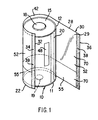
- Figure 1 is a perspective view of the flat-wrap label of the invention being applied around a battery cell casing.
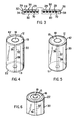
- Figure 2 is a plan view of a sheet of printed labels before they are cut.
- Figure 3 is a cross-sectional view of a printed label.
- Figure 4 is a perspective view of the label wrapped around a battery cell casing and showing the negative end of the cell.
- Figure 5 is a perspective view of the embodiment shown in figure 4 after the label has been exposed to heat to shrink the ends around the top and bottom shoulders of the cell.
- Figure 6 is a perspective view of the embodiment shown in figure 5, but showing the positive end of the cell.
-
- The present invention is directed to a label wrapped circumferentially around the outside surface (casing) of an electrochemical cell or battery, particularly cylindrical cells which are of standard AAA, AA, C or D sizes. These cell sizes are well established and as a group range in diameter between about 9 mm and 32 mm and in length between about 45 mm and 60 mm. The label of the invention is also specifically applicable to any cylindrical cell sizes having dimensions between these stated ranges. The leading edge of the label adheres to the cell and the trailing edge adheres to the outer surface of the adhered leading edge forming a permanent jacket around the cell's casing. The label is slightly longer than the length of the cell outer surface (casing) so that after the label is applied around it, a portion of the label extends beyond the casing top and bottom edges (shoulders). The shoulders of the cell forming the cell's top and bottom edges are defined as the end portions, respectively, of the cell casing which form a 90° angle with the body of the casing surface. The entire label is exposed to a quick dose of heat which is sufficient to cause the top and bottom ends of the label to shrink around the cell's shoulders. The main portion of the label which is snugly wrapped around the cell casing does not shrink appreciably, even though exposed to heat.
- The label preferably contains only a single sheet of heat-shrinkable polymeric film with decorative designs on the inside surface of the film facing the cell whereby the label and decorative designs thereon are abrasion resistant. They also resist degradation caused by corrosive atmospheres which may be present in the vicinity of the cell during its manufacture. In a preferred embodiment the decorative designs on the label have an attractive metallic appearance, but yet do not contain metallic inks and are not electrically conductive. Additionally, since the label is not pre-formed into a tubular shape and flattened, there are no crease lines appearing on the label surface.
- Preferred embodiments of the invention are shown in figures 1 to 6. As illustrated in figure 1,
label 30 contains a heat-shrinkable polymeric film 28 coated or imprinted on itsinside surface 29 with adecorative design layer 70. In figure 1label 30 is shown in the form of a flat-wrap label being wrapped around outer surface (casing) 20 ofbattery cell 10 with the label'sinside surface 29 andink design layer 70 facing the cell'souter surface 20.Casing 20 is typically of steel. - A coating of adhesive material or
glue 34 is first applied along the label's inside surface at leadingedge 32. The adhesive 34 may be a narrow strip of a pick-up adhesive preferably covering the entire width oflabel 30.Adhesive 34 may be selected from any conventional adhesive, or glue. It is not required that the adhesive have permanent bonding (peel) strength. Its function is merely to "pick-up" the label from the label-supply source and hold leadingedge 32 againstcasing 20 as the label is wrapped around the casing. As a result the adhesive may be selected from a wide variety of materials which are typically applied at ambient temperature. Hot melt adhesives may be employed but are less desirable, since care must be taken not to shrinkfilm 28. For example, adhesive 34 may be a solvent which when applied to the inside surface of leadingedge 32 causes it to become soft and tacky. Altemaltively, it may be a liquid which changes the interfacial surface tension sufficently to cause leadingedge 32 to adhere instantly to the body ofcell surface 20 once contact is made. (In this latter case or if adhesive 34 is very weak, some mechanical pressure may be exerted against leadingedge 32 to hold it againstcasing 20 aslabel 30 is wrapped around the casing.) A specificsuitable adhesive 34 is a household glue such as the well known Lepages paper glue manufactured by Lepages, Inc., Pittsburgh, Pennsylvania. This glue functions satisfactorily if applied along leadingedge 32 in a coating width typically of about 1 mm. - After leading
edge 32 instantly adheres tocell surface 20,label 30 is wrapped around the cell. Prior to label 30 being fully wrapped around the cell, bonding means 38 is applied in a strip along the inside surface at trailingedge 36. Bonding means 38 a reactive solven. The term "reactive solvent" as used herein is a solvent which when applied to a polymeric film causes it to soften or at least partially soften. This enables the film to fuse to itself when the solvent is applied between two of the film surfaces. A preferred solvent causes the label to begin to soften immediately on contact. Thus, aslabel 30 is wrapped around the cell's outer surface (casing) 20 and pressed against a portion of the exposed side of the la-bel 30, it permanently bonds or fuses thereto and forms Ja a secure wrap around the cell as shown in figure 4. The open bond is formed at overlappedportion 39 which is on the exposed side oflabel 30, typically at or near leadingedge 32. It is preferred that the solvent is volatile so that it substantially completely evaporates after the bond is formed. Thus, an adhesive is not required to form the bond and the bond formed with the solvent is adhesive-free similar to a cold weld. The above described method of bonding shall be referred to herein as solvent-fusing. The label is heat shrinkable, though flexible, and able to fuse to itself when the solvent is applied. Apreferred label 30 having these properties contains only a single layer of heat shrinkable polymeric film, preferably polyvinylchloride (PVC) film, however, polyethylene terephthalate film (PET) and glycol modified polyethylene terephthalate film (PETG), are also suitable.Label 30 is not intended to be limited to these materials as other heat shrinkable, flexible polymeric films can be employed. Iflabel 30 is composed of PVC film, then a preferred solvent 38 is tetrahydrofuran (THF). Eachlabel 30 at the time of application has a length in the cell's longitudinal axial direction which is slightly longer than the length ofcell surface 20 as measured between the top andbottom shoulders Shoulders top end 42 and a portion of itsbottom end 22 extend slightly beyond the cell's top andbottom shoulders Label 30 is also cut prior to application so that at right angles to its length it has a width which is greater than the circumference of the cell. Thus aslabel 30 is wrapped aroundcell surface 20 it completely surrounds the cell surface with trailingedge 36 overlapping leadingedge 32. - Those skilled in the art of labelling may consider it unusual and difficult to label small diameter cylindrical articles such as AAA, AA, C and D size cells by the above described method. This is because a film-label has a much greater tendency to spring away from the surface of small diameter objects than large diameter objects such as bottles and cans. This is caused by the natural recoil tension of polymeric films, which becomes greater when the film is wound around the smaller diameter object. Nevertheless, we have found that the labels herein can be adequately secured to small diameter cylindrical articles such as AAA, AA, C and D size cells even though only small portions of the label, as above described, are exposed to adhesive bonding and solvent-fusing.
- The
ink design layer 70 coated or imprinted ontoinside surface 29 offilm 28 contains the desired logo and decorative designs. Preferably, a non-corrosive ink is employed for all of theink design layer 70. The preferredink design layer 70 does not degrade if exposed to an alkaline environment such as may be present during manufacture of the cells. Also the ink should have a sufficiently low resistivity that it will not cause electrical shorting between the negative andpositive terminals polymeric film web 28, and avoids the need to sandwichink design layer 70 between two such polymeric films. This also makes it easier to heat seal the label's extended ends 22 and 42 over the cell shoulders 11 and 12, respectively. Also, the use of a single-ply label eliminates the need to preheat the cell before extended ends 22 and 42 are heat-shrunk overshoulders - A suitable non-metallic ink for
design layer 70 which has the above described properties can be selected from a class of inks known in the art as "pearlescent" inks. Such inks are composed of pigment, e.g., titanium dioxide, which is resistant to attack by KOH, a carrier (resin binder) and solvent as in metallic inks, but contain mica flakes instead of metallic particles. The carrier is typically selected from vinyl copolymers or acrylics. Compatible solvents may typically be ester solvents such as n-propyl acetate or ethyl acetate. The mica flakes are preferably coated with iron oxide or titanium oxide. The mica flakes are not electrically conductive and give the ink pigment a lustrous metallic appearance. This type of ink is preferred for the entireink design layer 70 or at least that portion of theink design 70, namelyportion 52 which is closest to the cell's negative terminal. The non-conductive nature ofink portion 52 prevents any chance of a short circuit developing caused by inadvertent contact betweenink portion 52 and the cell'snegative terminal 18. (This assumescell 10 is a conventional alkaline cell where thecell casing 20 is electrically positive.) If a metallic appearance is not required, a lustrous non-metallic ink, e.g a black ink suitable forink design layer 70 may be employed without the mica flakes. Such inks may be formulated by using non-conductive carbon black as the pigment. - A single sheet of heat stretchable
clear film stock 28, preferably of polyvinylchloride having a thickness of about 15.24 x 10⁻³ cm (6 mil) is subjected to heat-stretching in the machine direction to about 2.0 to 2.2 times its unstretched length. (The term "heat-stretching" as used herein refers to the known method of applying heat while stretching a polymeric film.) The clear film is typically heat-stretched in the transvere direction preferably up to 1.10 times its unstretched width, typically between about 1.03 to 1.05 times its unstretched width. The film is then imprinted on itsinside surface 29 with the desireddesign layer 70 employing preferably the non-metallic, non-conductive type inks above referenced. The ink may be imprinted employing conventional gravure or flexographic printing techniques. - The imprinted film contains a repetitive pattern of the ink design layer as shown in figure 2. The machine direction of the film is represented by the arrows A-A and the transverse direction by the arrows B-B in figure 2. The imprinted film is cut at
clear areas 57 which separate the repetitive design patterns. Individual labels are then formed which can be wrapped aroundcell 10 and secured to the cell in the manner above described.Label 30 is applied so that the machine direction (A-A) offilm 28 is in the cell's circumferential direction and the transverse direction (B-B) offilm 28 is in the cell's longitudinal axial direction. Since theink design layer 70 is non-corrosive and non-electrically conductive it can come into direct contact with thecell surface 20.Ink design layer 70 may be optionally coated with a thin coating of anon-conductive ink 80 containing titanium dioxide (Fig. 3). The purpose of this coating, if employed, is to enhance the colors ofink design layer 70 and to minimize show-through of can blemishes. - After the label is wrapped around
cell surface 20 and secured thereto byadhesive layer 34 and solvent-fusing as above described, the entire jacketed cell is briefly heated, preferably by passage through a heat tunnel (not shown).Label 30 adhered tocell surface 20 withends shoulders film 28 in the machine direction (direction A-A, Fig. 2) relative to the transverse direction. This causes the label's extended ends 22 and 42 to snap tightly over the cell'sshoulders - Since the body of
film 28 is wrapped around thecell casing 20 beforefilm 28 is subjected to heat, the film body shrinks only very little in relation to the amount of shrinkage of extended ends 22 and 42. In fact, the extended ends 22 and 42 shrink at least twice as much per unit area as the body portion offilm 28. A distortion-free label can conveniently be obtained by pre-stretch-ing the label in the machine direction between about 2.0 and 2.2 times its original (unstretched) length and only up to 1.1 times its unstretched length in the transverse direction priorto application ofink design layer 70. When the label is polyvinylchloride, the pre-stretching may suitably be accomplished at temperatures between about 110 and 121°C (230 and 250 °F.) - Since
label 30 of the invention does not crease when applied to the cell and is subjected to only a small amount of heat during application, the label is also well suited for covering and protecting certain thin devices which may be attached to the battery cell outer surface. Such devices, for example, may be thin-film voltage indicators which indicate the condition of the cell. A representative indicator of this type is disclosed in U.S patent 5,059,895. These indicators are of a film-laminate structure, typically having a thickness of less than 100 mil (2.5 mm). Such devices (48) can be located on battery cellouter surface 20 and electrically connected to to the cell terminals. They may be covered and held in place by thelabel 30 of the invention or alternatively, may be integrally affixed to the label or the cell before the label is applied around the cell. - Although the present invention was described with respect to preferred embodiments, it should be recognized that changes can be made in structure, placement, materials and the like without departing from the scope of the invention as defined in the claims. For example, the labels applied to the cells are not intended to be restricted to specific materials or specific formulations for the adhesive or ink design layers.
Claims (8)
- The combination of an electrochemical cell and a decorative label thereon; wherein the electrochemical cell has a longitudinal axis and comprises a metal casing having a cylindrical wall with first and second shoulders at opposite ends thereof; wherein the improvement comprises that said label is a heat-shrinkable film with a first edge aligned longitudinally and adhered to said cylindrical wall, a major portion of the label is adhesive free, substantially unshrunk, and tightly wrapped around said cylindrical wall; a second edge of the label overlaps and is bonded to the first edge thereof by solvent-fusing; and third and fourth edges of said label overlap said first and second shoulders; said third and fourth edges being shrunk into close contact with the ends of the electrochemical cell; and that said decorative label has indicia printed on the surface of said heat-shrinkable film contacting the cylindrical wall in a position where it can be viewed through a transparent portion thereof.
- The combination of claim 1 wherein the label comprises a heat-shrinkable polymeric film selected from the group consisting of polyvinylchloride (PVC), polyethylene terephthalate (PET), and glycol modified polyethylene terephthalate (PETG).
- The combination of claim 1 wherein the film is a single sheet which has been heat-stretched in the cell label's circumferential direction to between about 2.0 and 2.2 times the film's unstretched length in said circumferential direction and wherein the film was heat stretched in the cell label's longitudinal direction to between about 1.0 and 1.1 times said film's unstretched length in said longitudinal direction.
- The combination of claim 1 further comprising a cell condition indicator located between the cell casing and said decorative label.
- The combination of claim 1 wherein said label further includes an integral cell condition indicator.
- A method for applying a film label to an electrochemical cell having a cylindrical casing, comprising the steps of:a) heat-stretching a polymeric film in a first direction to a greater degree than in a second direction at right angles thereto;b) printing a cell label design on one surface of said film;c) cutting said film to form a label, said label having a length in the longitudinal axial direction of the cell greater than the length of the cell casing and a width at right angles thereto greater than the circumference of the cell and the major portion of the label is adhesive free;d) adhering a first edge of said label to the casing;e) wrapping said label around the casing such that said first direction follows the cell's circumference and said second direction is substantially parallel to the cell's longitudinal axial direction and a portion of the label extends beyond each end of the casing; andf) overlapping and bonding a second edge of said label to an adjacent portion of the outer surface of said first edge, wherein said second edge of the label is bonded to the outer surface of said first edge of the label by applying a volatile solvent which solvent is capable of softening said film between said first and second edges; andg) applying heat to the label to shrink said extending portions around the ends of the casing.
- The method of claim 6 including the step of applying a strip of adhesive to the first edge of the label on the same side of the label as the label design and parallel to the cell's longitudinal axial direction.
- The method of claim 6 wherein the film is heat-stretched in the first direction to between about 2.0 and 2.2 times said film's unstretched length in that direction and wherein the label is heat-stretched in the second direction to between about 1.0 and 1.1 times said label's unstretched length in said second direction.
Applications Claiming Priority (3)
| Application Number | Priority Date | Filing Date | Title |
|---|---|---|---|
| US1993193A | 1993-02-19 | 1993-02-19 | |
| US19931 | 1993-02-19 | ||
| PCT/US1994/001692 WO1994019835A1 (en) | 1993-02-19 | 1994-02-15 | Battery cell jacket |
Publications (4)
| Publication Number | Publication Date |
|---|---|
| EP0686311A1 EP0686311A1 (en) | 1995-12-13 |
| EP0686311A4 EP0686311A4 (en) | 1996-02-28 |
| EP0686311B1 EP0686311B1 (en) | 1997-10-22 |
| EP0686311B2 true EP0686311B2 (en) | 2003-04-09 |
Family
ID=21795826
Family Applications (1)
| Application Number | Title | Priority Date | Filing Date |
|---|---|---|---|
| EP94909661A Expired - Lifetime EP0686311B2 (en) | 1993-02-19 | 1994-02-15 | Battery cell jacket |
Country Status (11)
| Country | Link |
|---|---|
| US (2) | US5368953A (en) |
| EP (1) | EP0686311B2 (en) |
| JP (1) | JPH08507171A (en) |
| AT (1) | ATE159617T1 (en) |
| AU (1) | AU677302B2 (en) |
| BR (1) | BR9405731A (en) |
| CA (1) | CA2153977C (en) |
| DE (1) | DE69406431T3 (en) |
| ES (1) | ES2108433T5 (en) |
| TW (1) | TW242709B (en) |
| WO (1) | WO1994019835A1 (en) |
Families Citing this family (44)
| Publication number | Priority date | Publication date | Assignee | Title |
|---|---|---|---|---|
| US5766795A (en) * | 1984-08-16 | 1998-06-16 | Zweckform Etikettiertechnik Gmbh | Multilayer adhesive label |
| US5350482A (en) * | 1992-06-30 | 1994-09-27 | Cms Gilbreth Packaging Systems | Apparatus and method for applying labels onto small cylindrical articles |
| US5813538A (en) * | 1994-05-20 | 1998-09-29 | 3-Strikes Custom Design | Promotional package |
| JP3647924B2 (en) * | 1995-04-28 | 2005-05-18 | 株式会社フジシールインターナショナル | Thermal label for battery exterior |
| DE19681442T1 (en) * | 1995-06-07 | 1998-07-02 | Avery Dennison Corp | Single-layer PSA labels for battery applications |
| US5747192A (en) * | 1995-06-07 | 1998-05-05 | Avery Dennison Corporation | Single ply PSA labels for battery applications |
| DE29513170U1 (en) | 1995-08-16 | 1997-01-02 | Zweckform Etikettiertechnik | Adhesive label |
| EP0857348A4 (en) * | 1995-10-07 | 2000-07-05 | Bemis Co Inc | An electrical circuit component formed of a conductive liquid printed directly onto a substrate |
| GB9525242D0 (en) * | 1995-12-09 | 1996-02-07 | Simpson Label Co Ltd | Improvements in and relating to labels |
| US5725966A (en) * | 1996-01-25 | 1998-03-10 | Matsushita Electric Industrial Co., Ltd. | Heat sensitive jacket label for battery and battery with the same |
| DE19643011A1 (en) * | 1996-10-18 | 1998-04-23 | Varta Batterie | Directly overprinted galvanic element |
| IT1292470B1 (en) * | 1997-07-04 | 1999-02-08 | Ilario Carizzoni | PROCEDURE AND APPARATUS FOR PRINTING AND DECORATING USING SUBLIMABLE INKS |
| US5958618A (en) * | 1997-10-14 | 1999-09-28 | Motorola, Inc. | Battery assembly |
| US6127024A (en) * | 1998-05-21 | 2000-10-03 | Morgan Adhesives Company | Single ply battery label including varnish with patterned edges |
| AU1450000A (en) * | 1998-10-21 | 2000-05-08 | Dispensing Containers Corporation | Corrosion inhibiting labels for container exteriors |
| US6589690B1 (en) * | 1999-03-30 | 2003-07-08 | Kabushiki Kaisha Toshiba | Secondary battery |
| US6294287B1 (en) | 1999-08-18 | 2001-09-25 | The Gillette Company | Alkaline cell with insulator |
| EP1089370A1 (en) * | 1999-09-30 | 2001-04-04 | Sony Corporation | Solid electrolyte cell |
| NL1014591C2 (en) * | 2000-03-09 | 2001-09-11 | Corus Staal Bv | Battery of the type comprising a zinc canister and a carbon collector for the cathode. |
| NL1014590C2 (en) * | 2000-03-09 | 2001-09-11 | Corus Staal Bv | Battery comprising several galvanic cells connected in series. |
| US7258368B2 (en) * | 2001-08-10 | 2007-08-21 | Quality Assured Enterprises, Inc. | Extended text wrap label and method of manufacture thereof |
| US6755442B2 (en) * | 2001-08-10 | 2004-06-29 | Quality Assured Enterprises, Inc. | Extended text wrap label and method of manufacture thereof |
| US20030049522A1 (en) * | 2001-09-12 | 2003-03-13 | Doomernik Marinus A. | Battery tester label |
| US6764233B2 (en) * | 2002-03-14 | 2004-07-20 | Hewlett-Packard Development Company, L.P. | Apparatus and methods for the use of shrinkable print media |
| US7273504B2 (en) * | 2002-03-27 | 2007-09-25 | Sanyo Electric Co., Ltd. | Battery and a method of manufacturing same |
| US7448497B2 (en) * | 2002-12-30 | 2008-11-11 | Fck, Llc. | Batteries, accessories, marketing bundles and marketing methods |
| US20050255262A1 (en) * | 2004-05-11 | 2005-11-17 | Sonoco Development, Inc. | Composite container having an electromagnetic surveillance device |
| TWI328892B (en) | 2005-08-12 | 2010-08-11 | Sony Corp | Secondary battery |
| KR101491876B1 (en) * | 2008-02-27 | 2015-02-09 | 도요보 가부시키가이샤 | Heat-shrinkable white polyester film, process for producing heat-shrinkable white polyester film, label, and package |
| US8389117B2 (en) * | 2008-10-30 | 2013-03-05 | Eastman Chemical Company | Hot melt adhesives for roll-applied labels |
| US8182937B2 (en) * | 2008-11-03 | 2012-05-22 | The Gillette Company | Battery having battery-life indicator with fragrance |
| IT1396834B1 (en) | 2009-11-18 | 2012-12-14 | Sacmi Labelling S P A Ora Sacmi Verona S P A | PROCEDURE FOR THE PRODUCTION OF SLEEVE LABELS AND DEVICE FOR THEIR PRODUCTION. |
| IT1396835B1 (en) * | 2009-11-18 | 2012-12-14 | Sacmi Labelling S P A Ora Sacmi Verona S P A | PROCEDURE FOR THE PRODUCTION OF SLEEVE LABELS AND DEVICE FOR THEIR PRODUCTION. |
| JP5486676B2 (en) * | 2010-03-31 | 2014-05-07 | 株式会社フジシールインターナショナル | Label strip for dry batteries |
| FR2967474B1 (en) * | 2010-11-17 | 2013-10-04 | Berkem Dev | THERMO-RETRACTABLE PROTECTION BARRIER |
| WO2013112531A2 (en) * | 2012-01-23 | 2013-08-01 | Avery Dennison Corporation | Electrochemical cell labels and accessories |
| US20150147500A1 (en) * | 2013-11-25 | 2015-05-28 | Tyco Electronics Corporation | Heat shrinkable tube |
| KR102070369B1 (en) * | 2015-09-03 | 2020-01-28 | 주식회사 엘지화학 | Cable-type secondary battery and method for manufacturing the same |
| US20180226784A1 (en) * | 2017-02-05 | 2018-08-09 | John Matthew Shull | Adaptable Heat Shrink Tubing |
| EP3605506B1 (en) * | 2017-03-24 | 2023-08-16 | Toyobo Co., Ltd. | Heat-shrinkable label, packaging body, and manufacturing method for heat-shrinkable label |
| KR102473094B1 (en) | 2018-01-26 | 2022-12-01 | 삼성에스디아이 주식회사 | Battery pack and method for attaching label thereof |
| US20190267639A1 (en) * | 2018-02-28 | 2019-08-29 | Mingrong Zhao | Battery Cells With Removable Elements |
| CN111890672A (en) * | 2020-07-17 | 2020-11-06 | 屈紫懿 | New forms of energy power battery cover pyrocondensation pipe machine |
| CN114986869A (en) * | 2022-05-31 | 2022-09-02 | 谢维 | Lithium battery heat treatment film pasting device and method |
Citations (6)
| Publication number | Priority date | Publication date | Assignee | Title |
|---|---|---|---|---|
| DE3430162A1 (en) † | 1983-06-21 | 1986-02-27 | Zweckform Werk Gmbh, 8150 Holzkirchen | Multi-layer adhesive label which is shrinkable onto a circumferential surface of a body |
| GB2184672A (en) † | 1985-11-20 | 1987-07-01 | Dainippon Printing Co Ltd | Packaging materials |
| US4704173A (en) † | 1982-05-27 | 1987-11-03 | Wolfgang Hoffman | System for applying heat shrink film to containers and other articles and heat shrinking the same |
| DE3442995C2 (en) † | 1983-11-28 | 1990-01-25 | Owens-Illinois, Inc., Toledo, Ohio, Us | |
| DE4125472A1 (en) † | 1991-08-01 | 1993-02-04 | Kronseder Maschf Krones | METHOD AND DEVICE FOR EQUIPPING VESSELS WITH A LABEL FROM SEALABLE MATERIAL AND VESSELS EQUIPPED THEREFORE |
| EP0450938B1 (en) † | 1990-04-04 | 1995-12-20 | Eastman Kodak Company | Battery having a label comprising a voltmeter |
Family Cites Families (6)
| Publication number | Priority date | Publication date | Assignee | Title |
|---|---|---|---|---|
| US3630783A (en) * | 1970-05-11 | 1971-12-28 | Mallory Battery Canada | Heat-shrinkable packaging for batteries |
| DE3275409D1 (en) * | 1981-07-21 | 1987-03-12 | Hitachi Ltd | Method of manufacturing a gas sensor |
| US4511416A (en) * | 1981-12-08 | 1985-04-16 | Duracell Inc. | Method for making decorated battery casings |
| CA1296891C (en) * | 1984-08-16 | 1992-03-10 | Rolf Will | Multilayer adhesive label |
| US4608323A (en) * | 1985-03-07 | 1986-08-26 | Duracell Inc. | Cell jacket |
| NZ226616A (en) * | 1987-10-22 | 1991-07-26 | Mitsui Toatsu Chemicals | Heat-shrinking an extruded cylindrical label onto a container: extruded label stretched in direction of extrusion prior to heat-shrinking |
-
1994
- 1994-02-15 AU AU62540/94A patent/AU677302B2/en not_active Ceased
- 1994-02-15 DE DE69406431T patent/DE69406431T3/en not_active Expired - Lifetime
- 1994-02-15 JP JP6519117A patent/JPH08507171A/en not_active Ceased
- 1994-02-15 WO PCT/US1994/001692 patent/WO1994019835A1/en active IP Right Grant
- 1994-02-15 EP EP94909661A patent/EP0686311B2/en not_active Expired - Lifetime
- 1994-02-15 ES ES94909661T patent/ES2108433T5/en not_active Expired - Lifetime
- 1994-02-15 BR BR9405731A patent/BR9405731A/en not_active IP Right Cessation
- 1994-02-15 AT AT94909661T patent/ATE159617T1/en not_active IP Right Cessation
- 1994-02-15 CA CA002153977A patent/CA2153977C/en not_active Expired - Fee Related
- 1994-03-14 US US08/214,711 patent/US5368953A/en not_active Expired - Lifetime
- 1994-05-25 TW TW083104725A patent/TW242709B/zh active
- 1994-10-11 US US08/321,188 patent/US5443668A/en not_active Expired - Lifetime
Patent Citations (6)
| Publication number | Priority date | Publication date | Assignee | Title |
|---|---|---|---|---|
| US4704173A (en) † | 1982-05-27 | 1987-11-03 | Wolfgang Hoffman | System for applying heat shrink film to containers and other articles and heat shrinking the same |
| DE3430162A1 (en) † | 1983-06-21 | 1986-02-27 | Zweckform Werk Gmbh, 8150 Holzkirchen | Multi-layer adhesive label which is shrinkable onto a circumferential surface of a body |
| DE3442995C2 (en) † | 1983-11-28 | 1990-01-25 | Owens-Illinois, Inc., Toledo, Ohio, Us | |
| GB2184672A (en) † | 1985-11-20 | 1987-07-01 | Dainippon Printing Co Ltd | Packaging materials |
| EP0450938B1 (en) † | 1990-04-04 | 1995-12-20 | Eastman Kodak Company | Battery having a label comprising a voltmeter |
| DE4125472A1 (en) † | 1991-08-01 | 1993-02-04 | Kronseder Maschf Krones | METHOD AND DEVICE FOR EQUIPPING VESSELS WITH A LABEL FROM SEALABLE MATERIAL AND VESSELS EQUIPPED THEREFORE |
Non-Patent Citations (2)
| Title |
|---|
| JP 52-25236 ( with english translation ) † |
| Prospekt Krones "KRONES Contiroll" † |
Also Published As
| Publication number | Publication date |
|---|---|
| BR9405731A (en) | 1995-11-28 |
| US5443668A (en) | 1995-08-22 |
| AU677302B2 (en) | 1997-04-17 |
| CA2153977A1 (en) | 1994-09-01 |
| EP0686311A4 (en) | 1996-02-28 |
| ES2108433T3 (en) | 1997-12-16 |
| AU6254094A (en) | 1994-09-14 |
| DE69406431T2 (en) | 1998-02-26 |
| ATE159617T1 (en) | 1997-11-15 |
| EP0686311A1 (en) | 1995-12-13 |
| WO1994019835A1 (en) | 1994-09-01 |
| DE69406431D1 (en) | 1997-11-27 |
| US5368953A (en) | 1994-11-29 |
| JPH08507171A (en) | 1996-07-30 |
| CA2153977C (en) | 1999-11-02 |
| DE69406431T3 (en) | 2004-03-04 |
| EP0686311B1 (en) | 1997-10-22 |
| ES2108433T5 (en) | 2003-11-01 |
| TW242709B (en) | 1995-03-11 |
Similar Documents
| Publication | Publication Date | Title |
|---|---|---|
| EP0686311B2 (en) | Battery cell jacket | |
| US4608323A (en) | Cell jacket | |
| KR100406015B1 (en) | Single ply psa labels for battery applications | |
| KR100258014B1 (en) | A heat sensitive jacket label for battery and battery with the same | |
| US4436777A (en) | Method for making decorated battery casings | |
| US6127024A (en) | Single ply battery label including varnish with patterned edges | |
| WO1996042115A9 (en) | Single ply psa label for battery applications | |
| US4511416A (en) | Method for making decorated battery casings | |
| US20040185235A1 (en) | Shrinkable battery label | |
| CA2223952C (en) | Single ply psa labels for battery applications | |
| JP2003058057A (en) | Label for manganese battery and method of manufacturing manganese battery | |
| EP1154499B1 (en) | Battery | |
| JPH09237614A (en) | Label-fitted battery | |
| JP3874640B2 (en) | Cylindrical battery and method of sealing cylindrical battery with label | |
| JPH0713489A (en) | Label | |
| GB2198412A (en) | Labels for canisters | |
| FR2715494A1 (en) | Label for battery of stretchable or heat shrinkable plastic | |
| JPS61220269A (en) | Dry cell and manufacturing method thereof | |
| JPH09204908A (en) | Thermosensitive label for dry battery facing, and dry battery with thermosensitive label | |
| JPH03202341A (en) | Heat shrinkable film | |
| JP3634668B2 (en) | Single layer battery label with patterned varnish | |
| JP4100781B2 (en) | Battery and manufacturing method thereof | |
| JPS6278663U (en) | ||
| JPH09249238A (en) | Metal tube for adhesive | |
| JPH07271300A (en) | Label |
Legal Events
| Date | Code | Title | Description |
|---|---|---|---|
| PUAI | Public reference made under article 153(3) epc to a published international application that has entered the european phase |
Free format text: ORIGINAL CODE: 0009012 |
|
| 17P | Request for examination filed |
Effective date: 19950802 |
|
| AK | Designated contracting states |
Kind code of ref document: A1 Designated state(s): AT BE CH DE DK ES FR GB GR IE IT LI LU MC NL PT SE |
|
| A4 | Supplementary search report drawn up and despatched |
Effective date: 19960115 |
|
| AK | Designated contracting states |
Kind code of ref document: A4 Designated state(s): AT BE CH DE DK ES FR GB GR IE IT LI LU MC NL PT SE |
|
| GRAG | Despatch of communication of intention to grant |
Free format text: ORIGINAL CODE: EPIDOS AGRA |
|
| 17Q | First examination report despatched |
Effective date: 19961209 |
|
| GRAH | Despatch of communication of intention to grant a patent |
Free format text: ORIGINAL CODE: EPIDOS IGRA |
|
| GRAH | Despatch of communication of intention to grant a patent |
Free format text: ORIGINAL CODE: EPIDOS IGRA |
|
| GRAA | (expected) grant |
Free format text: ORIGINAL CODE: 0009210 |
|
| AK | Designated contracting states |
Kind code of ref document: B1 Designated state(s): AT BE CH DE DK ES FR GB GR IE IT LI LU MC NL PT SE |
|
| PG25 | Lapsed in a contracting state [announced via postgrant information from national office to epo] |
Ref country code: LI Free format text: LAPSE BECAUSE OF FAILURE TO SUBMIT A TRANSLATION OF THE DESCRIPTION OR TO PAY THE FEE WITHIN THE PRESCRIBED TIME-LIMIT Effective date: 19971022 Ref country code: GR Free format text: LAPSE BECAUSE OF FAILURE TO SUBMIT A TRANSLATION OF THE DESCRIPTION OR TO PAY THE FEE WITHIN THE PRESCRIBED TIME-LIMIT Effective date: 19971022 Ref country code: DK Free format text: LAPSE BECAUSE OF NON-PAYMENT OF DUE FEES Effective date: 19971022 Ref country code: CH Free format text: LAPSE BECAUSE OF FAILURE TO SUBMIT A TRANSLATION OF THE DESCRIPTION OR TO PAY THE FEE WITHIN THE PRESCRIBED TIME-LIMIT Effective date: 19971022 Ref country code: AT Free format text: LAPSE BECAUSE OF FAILURE TO SUBMIT A TRANSLATION OF THE DESCRIPTION OR TO PAY THE FEE WITHIN THE PRESCRIBED TIME-LIMIT Effective date: 19971022 |
|
| REF | Corresponds to: |
Ref document number: 159617 Country of ref document: AT Date of ref document: 19971115 Kind code of ref document: T |
|
| REG | Reference to a national code |
Ref country code: CH Ref legal event code: EP |
|
| REF | Corresponds to: |
Ref document number: 69406431 Country of ref document: DE Date of ref document: 19971127 |
|
| REG | Reference to a national code |
Ref country code: ES Ref legal event code: FG2A Ref document number: 2108433 Country of ref document: ES Kind code of ref document: T3 |
|
| ITF | It: translation for a ep patent filed |
Owner name: STUDIO TORTA S.R.L. |
|
| ET | Fr: translation filed | ||
| PG25 | Lapsed in a contracting state [announced via postgrant information from national office to epo] |
Ref country code: SE Effective date: 19980122 Ref country code: PT Free format text: LAPSE BECAUSE OF FAILURE TO SUBMIT A TRANSLATION OF THE DESCRIPTION OR TO PAY THE FEE WITHIN THE PRESCRIBED TIME-LIMIT Effective date: 19980122 |
|
| PG25 | Lapsed in a contracting state [announced via postgrant information from national office to epo] |
Ref country code: LU Free format text: LAPSE BECAUSE OF NON-PAYMENT OF DUE FEES Effective date: 19980215 |
|
| PG25 | Lapsed in a contracting state [announced via postgrant information from national office to epo] |
Ref country code: IE Free format text: LAPSE BECAUSE OF NON-PAYMENT OF DUE FEES Effective date: 19980216 |
|
| REG | Reference to a national code |
Ref country code: CH Ref legal event code: PL |
|
| PLBQ | Unpublished change to opponent data |
Free format text: ORIGINAL CODE: EPIDOS OPPO |
|
| PLBI | Opposition filed |
Free format text: ORIGINAL CODE: 0009260 |
|
| PLBF | Reply of patent proprietor to notice(s) of opposition |
Free format text: ORIGINAL CODE: EPIDOS OBSO |
|
| PG25 | Lapsed in a contracting state [announced via postgrant information from national office to epo] |
Ref country code: MC Free format text: LAPSE BECAUSE OF NON-PAYMENT OF DUE FEES Effective date: 19980831 |
|
| 26 | Opposition filed |
Opponent name: ZWECKFORM ETIKETTIERTECHNIK GMBH Effective date: 19980722 |
|
| NLR1 | Nl: opposition has been filed with the epo |
Opponent name: ZWECKFORM ETIKETTIERTECHNIK GMBH |
|
| PLBF | Reply of patent proprietor to notice(s) of opposition |
Free format text: ORIGINAL CODE: EPIDOS OBSO |
|
| PLBF | Reply of patent proprietor to notice(s) of opposition |
Free format text: ORIGINAL CODE: EPIDOS OBSO |
|
| PLBF | Reply of patent proprietor to notice(s) of opposition |
Free format text: ORIGINAL CODE: EPIDOS OBSO |
|
| PLBF | Reply of patent proprietor to notice(s) of opposition |
Free format text: ORIGINAL CODE: EPIDOS OBSO |
|
| PLAB | Opposition data, opponent's data or that of the opponent's representative modified |
Free format text: ORIGINAL CODE: 0009299OPPO |
|
| R26 | Opposition filed (corrected) |
Opponent name: STEINBEIS PACKAGING GMBH Effective date: 19980722 |
|
| NLR1 | Nl: opposition has been filed with the epo |
Opponent name: STEINBEIS PACKAGING GMBH |
|
| PLAB | Opposition data, opponent's data or that of the opponent's representative modified |
Free format text: ORIGINAL CODE: 0009299OPPO |
|
| R26 | Opposition filed (corrected) |
Opponent name: STEINBEIS PACKAGING GMBH & CO.KG Effective date: 19980722 |
|
| NLR1 | Nl: opposition has been filed with the epo |
Opponent name: STEINBEIS PACKAGING GMBH & CO.KG |
|
| REG | Reference to a national code |
Ref country code: GB Ref legal event code: IF02 |
|
| PLAW | Interlocutory decision in opposition |
Free format text: ORIGINAL CODE: EPIDOS IDOP |
|
| PLAW | Interlocutory decision in opposition |
Free format text: ORIGINAL CODE: EPIDOS IDOP |
|
| PGFP | Annual fee paid to national office [announced via postgrant information from national office to epo] |
Ref country code: FR Payment date: 20030117 Year of fee payment: 10 |
|
| PGFP | Annual fee paid to national office [announced via postgrant information from national office to epo] |
Ref country code: NL Payment date: 20030121 Year of fee payment: 10 |
|
| PUAH | Patent maintained in amended form |
Free format text: ORIGINAL CODE: 0009272 |
|
| STAA | Information on the status of an ep patent application or granted ep patent |
Free format text: STATUS: PATENT MAINTAINED AS AMENDED |
|
| PGFP | Annual fee paid to national office [announced via postgrant information from national office to epo] |
Ref country code: ES Payment date: 20030311 Year of fee payment: 10 |
|
| 27A | Patent maintained in amended form |
Effective date: 20030409 |
|
| AK | Designated contracting states |
Designated state(s): AT BE CH DE DK ES FR GB GR IE IT LI LU MC NL PT SE |
|
| NLR3 | Nl: receipt of modified translations in the netherlands language after an opposition procedure | ||
| REG | Reference to a national code |
Ref country code: ES Ref legal event code: DC2A Date of ref document: 20030523 Kind code of ref document: T5 |
|
| ET3 | Fr: translation filed ** decision concerning opposition | ||
| PG25 | Lapsed in a contracting state [announced via postgrant information from national office to epo] |
Ref country code: ES Free format text: LAPSE BECAUSE OF NON-PAYMENT OF DUE FEES Effective date: 20040216 |
|
| PG25 | Lapsed in a contracting state [announced via postgrant information from national office to epo] |
Ref country code: NL Free format text: LAPSE BECAUSE OF NON-PAYMENT OF DUE FEES Effective date: 20040901 |
|
| PG25 | Lapsed in a contracting state [announced via postgrant information from national office to epo] |
Ref country code: FR Free format text: LAPSE BECAUSE OF NON-PAYMENT OF DUE FEES Effective date: 20041029 |
|
| NLV4 | Nl: lapsed or anulled due to non-payment of the annual fee |
Effective date: 20040901 |
|
| REG | Reference to a national code |
Ref country code: FR Ref legal event code: ST |
|
| PG25 | Lapsed in a contracting state [announced via postgrant information from national office to epo] |
Ref country code: IT Free format text: LAPSE BECAUSE OF NON-PAYMENT OF DUE FEES;WARNING: LAPSES OF ITALIAN PATENTS WITH EFFECTIVE DATE BEFORE 2007 MAY HAVE OCCURRED AT ANY TIME BEFORE 2007. THE CORRECT EFFECTIVE DATE MAY BE DIFFERENT FROM THE ONE RECORDED. Effective date: 20050215 |
|
| REG | Reference to a national code |
Ref country code: ES Ref legal event code: FD2A Effective date: 20040216 |
|
| REG | Reference to a national code |
Ref country code: GB Ref legal event code: 732E |
|
| PLAB | Opposition data, opponent's data or that of the opponent's representative modified |
Free format text: ORIGINAL CODE: 0009299OPPO |
|
| PGFP | Annual fee paid to national office [announced via postgrant information from national office to epo] |
Ref country code: GB Payment date: 20100107 Year of fee payment: 17 Ref country code: DE Payment date: 20100226 Year of fee payment: 17 |
|
| PGFP | Annual fee paid to national office [announced via postgrant information from national office to epo] |
Ref country code: BE Payment date: 20100402 Year of fee payment: 17 |
|
| BERE | Be: lapsed |
Owner name: THE *GILLETTE CY Effective date: 20110228 |
|
| GBPC | Gb: european patent ceased through non-payment of renewal fee |
Effective date: 20110215 |
|
| PG25 | Lapsed in a contracting state [announced via postgrant information from national office to epo] |
Ref country code: BE Free format text: LAPSE BECAUSE OF NON-PAYMENT OF DUE FEES Effective date: 20110228 |
|
| REG | Reference to a national code |
Ref country code: DE Ref legal event code: R119 Ref document number: 69406431 Country of ref document: DE Effective date: 20110901 |
|
| PG25 | Lapsed in a contracting state [announced via postgrant information from national office to epo] |
Ref country code: GB Free format text: LAPSE BECAUSE OF NON-PAYMENT OF DUE FEES Effective date: 20110215 |
|
| PG25 | Lapsed in a contracting state [announced via postgrant information from national office to epo] |
Ref country code: DE Free format text: LAPSE BECAUSE OF NON-PAYMENT OF DUE FEES Effective date: 20110901 |