EP0686593A2 - Method and apparatus for stacking - Google Patents
Method and apparatus for stacking Download PDFInfo
- Publication number
- EP0686593A2 EP0686593A2 EP95107899A EP95107899A EP0686593A2 EP 0686593 A2 EP0686593 A2 EP 0686593A2 EP 95107899 A EP95107899 A EP 95107899A EP 95107899 A EP95107899 A EP 95107899A EP 0686593 A2 EP0686593 A2 EP 0686593A2
- Authority
- EP
- European Patent Office
- Prior art keywords
- stack
- carrying
- separating
- fork
- forks
- Prior art date
- Legal status (The legal status is an assumption and is not a legal conclusion. Google has not performed a legal analysis and makes no representation as to the accuracy of the status listed.)
- Granted
Links
Images


Classifications
-
- B—PERFORMING OPERATIONS; TRANSPORTING
- B65—CONVEYING; PACKING; STORING; HANDLING THIN OR FILAMENTARY MATERIAL
- B65H—HANDLING THIN OR FILAMENTARY MATERIAL, e.g. SHEETS, WEBS, CABLES
- B65H45/00—Folding thin material
- B65H45/12—Folding articles or webs with application of pressure to define or form crease lines
- B65H45/24—Interfolding sheets, e.g. cigarette or toilet papers
-
- B—PERFORMING OPERATIONS; TRANSPORTING
- B65—CONVEYING; PACKING; STORING; HANDLING THIN OR FILAMENTARY MATERIAL
- B65H—HANDLING THIN OR FILAMENTARY MATERIAL, e.g. SHEETS, WEBS, CABLES
- B65H31/00—Pile receivers
- B65H31/32—Auxiliary devices for receiving articles during removal of a completed pile
-
- B—PERFORMING OPERATIONS; TRANSPORTING
- B65—CONVEYING; PACKING; STORING; HANDLING THIN OR FILAMENTARY MATERIAL
- B65H—HANDLING THIN OR FILAMENTARY MATERIAL, e.g. SHEETS, WEBS, CABLES
- B65H2701/00—Handled material; Storage means
- B65H2701/10—Handled articles or webs
- B65H2701/19—Specific article or web
- B65H2701/1924—Napkins or tissues, e.g. dressings, toweling, serviettes, kitchen paper and compresses
Definitions
- the invention relates to a method and a device for stacking folded, zigzag-shaped towels, one inside the other, with the fold alternatingly arriving on the left or left on a lowerable support device serving as a stacking table using a separating and auxiliary carrying device be filed.
- a device of the type mentioned is known from US Pat. No. 4,770,402 and has two folding cylinders which are parallel to one another, scraper fingers and below the folding cylinder a lowerable stacking table on which the parts are placed. After the desired stack height has been reached, separating fingers lie on the stack and at the same time serve as a carrier for the parts that are continuously deposited. In order to transfer the stack from the stacking table to another carrier, a sliding piece which is movable transversely to the lifting direction of the stack is provided. The stack is also deposited in a shaft which supports the stack laterally when the separating and carrying fingers are pulled out laterally when the new, partially formed stack is delivered to the stacking table.
- the invention is therefore based on the object of specifying a method and a device of the type mentioned, with the aid of which it is possible to deposit precisely and precisely those tissues which are difficult to handle due to their unstable shape.
- the invention provides that the stack is gripped and carried to a sufficient width and from opposite sides during stack formation and when lowering.
- the stack is preferably only partially grasped from two sides.
- This special form of support means that the stack is oriented in the manner of a centering. This orientation stabilizes the individual towels and the stack as a whole.
- the primarily eccentric support leads to the fact that the support surface of the lowerable stacking table is formed by two surfaces, each of which only partially engages under the stack and is easier to remove when the stack is handed over to a further transporting element than a supporting part carrying the stack over a large area. Even after the stack has been transferred from the stacking table to a shelf or to a conveyor belt or the like, the individual sheets in the stack are therefore properly aligned.
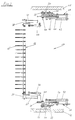
- a device 1 for stacking folded, zigzag-shaped sheets 3 stored one inside the other comprises, as shown in FIG. 1, two sets of rolls 4 and 5 for the individually or web-arriving sheets 3 and two folding cylinders 6, 7, of which the sheets 3 are placed with their folds alternately on the right and left on a lowerable support device serving as a stacking table 8.
- This is also done using separating and auxiliary carrying devices 9, 10, each of which has separating and carrying forks 11, 12 and whose function is basically known, as is the function of scraper fingers 13 and 14 which cooperate with folding cylinders 6, 7 in the formation of folds and stacking are.
- the supporting device serving as a stacking table 8 consists of two stack carrying devices 15, 16 arranged opposite one another (FIG. 1). Basically, the two separating and auxiliary carrying devices 9, 10 and the two stack carrying devices 15, 16 are in principle arranged in mirror image to a central plane 17 and are thus from two opposite sides 18, 19 (FIGS. 4, 5) during the stack formation and effective for stacking.
- the cloths 3 are carried off-center and in sufficient width, especially in the area of mutually opposite edges 20, 21 (FIG. 5), during the stack formation and during stack stacking. This applies both to the finished stack 2 and to a stack 2 'which is still being created (FIGS. 6 and 7).
- a stack 2 is separated during the continuous stack formation and from the next stack 2 ′ which is being formed from the two sides 18, 19.
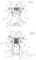
- the stack carrying devices 15 and 16 have carrying forks 22 and 23, which are arranged on supports 24, 25 and are directly supporting, for carrying the nascent stack 2 '(FIG. 4) or the finished stack 2 (FIG. 5) are movable together in the stroke direction of the stack 2 and transversely thereto, as is also indicated by the double arrows a and b in FIG. 8.
- the stacking and carrying devices 15, 16 are therefore able to deliver a stack 2 onto a conveyor belt 26 running directly below it, for which purpose their carrying forks 22 and 23 are moved from the position according to FIG. 7 are moved away from each other in the direction of the double arrow b in FIG. 8.
- the carrying forks 22, 23 are pulled out from under the stack 2 in opposite directions or in the direction of the sides 18 and 19 and the stack 2 sinks onto the conveyor belt 26. At the same time, the bottom cloth 3 is pulled tight (FIG. 7).
- the separating and carrying forks 11, 12 belonging to the two separating and auxiliary carrying devices 9 and 10 also overlap the stack 2 from the two mutually opposite sides 18 and 19, when they are pushed as separating elements when the required stack height is reached between two stored cloths 3.
- the separating and carrying forks 11 and 12 then also lie only partially on the finished stack 2 and only overlap it from the edges 20, 21, as shown in the figures 1, 5 and 6 is shown.
- the separating and carrying forks 11, 12 each support and support the nascent stack 2 'primarily off-center, as is the case with the carrying forks 22 and 23.
- the separating and carrying forks 11, 12 are finally displaceable at an angle to the stroke direction of the stack carrying devices 15, 16 and pivotally mounted on two supports 27 and 28, respectively, and together with the respective supports 27, 28 in the lifting direction of the stack carrying devices 15, 16 movable in a guide 29, 30.
- Each stack-carrying device 15, 16 also comprises two carriers 31, 32 which can be moved along the same guides 29, 30 in the lifting direction.
- the separating and carrying forks 11, 12 each have fingers 11 'and 12', and equally the carrying forks 22, 23 are each provided with fingers 22 'and 23' (FIG. 4).
- the fingers 11 'and 12' are arranged offset to the fingers 22 'and 23' transversely to the lifting movement of the carrying forks 22, 23, that is to say transversely to the axis of the guides 29, 30.
- the wiper fingers 13 and 14 are offset from the fingers 11 'and 12' and aligned with the fingers 22 'and 23'. It is thereby achieved that the separating and carrying forks 11, 12 can both reach between the stripper fingers 13, 14 (FIG. 4) and also dip into the carrying forks 22, 23 (FIG. 8).
- shaft walls 52, 53 (FIG. 1 and FIG. 5) have a stabilizing effect.
- the shaft walls 52, 53 are further provided with slots, not shown, through which the fingers 11 ', 12' and 22 ', 23' reach.
- the supports 27, 28 and 31, 32 used for storage and guidance have rollers 33 and can be moved along the guides 29 and 30 with the aid of these rollers 33.
- drives 34 and 35 also serve, for example in the form of chain or belt drives with associated electric motors 36 and 37 (FIGS. 1, 2).
- the separating and carrying fork 12 - and the same applies to the other separating and carrying fork 11 - is supported with each of its ends 38, 39 on a respective carrier 28 and is thus supported on two in FIG. 1 guides 30 arranged one behind the other.
- a pneumatic drive 43 for example, is used to move the separating and carrying fork 12, which engages on the guide element 41 and moves or displaces the separating and carrying fork 12 via this.
- the two ends 38 and 39 of the separation and carrying fork 12 are finally pivotally mounted in the two associated holders 42 and are each with the help of another, for. B. pneumatic drive 44 is pivoted.
- rollers 33 On the respective carrier 32 of the stack carrying device 16 there are rollers 33, with the aid of which the carrier 32 can be moved along the guide 30. Both guides 30 are attached to parts 45 and 46 of the machine frame 47.
- each carrier 32 has carrying and guide rollers 48 for a guide element 49, on the free end 50 of which the carrying fork 23 is attached.
- a pneumatic drive 51 for example, is supported on each carrier 32. Together they serve to move the carrying fork 23.
- FIG. 8 finally shows the movements of the two stripper fingers 13 and 14 which are effective during the folding and depositing process, and from FIG. 9 details are again shown in which form the separating and carrying forks 11 and 12 move.
- the separating and carrying forks 11, 12 can be pivoted and according to the two double arrows d they can be moved in the lifting direction of the stack 2.
- the separating and carrying forks 11, 12 can be moved obliquely to the lifting direction in the direction of the double arrows e.
- FIG. 10 The position of the individual sheets 3 between the shaft walls 52, 53 in connection with fingers 11 'or 12' of the two separating and carrying forks 11 or 12 and the fingers 22 'used according to a preferred embodiment is shown schematically in FIG. 10. or 23 'of the two carrying forks 22 and 23.
- edge part 3 'of the bottom cloth 3 of the nascent stack 2' hangs over the free edge of the fingers 11 'of the separating and carrying fork 11 when the complete stack 2 is removed downwards.
- the same applies to the bottom cloth 3 of the stack 2 because the edge part 3 'of the cloth 3 located below the fingers 23' also hangs down there during the downward movement of the stack 2.
- the edge part 3 'of the To reach the bottom cloth 3 the edge part 3 'is blown shortly before the stack 2 is placed on a tray or on the conveyor belt 26 with the aid of a flow medium or with the aid of air. This is preferably done in such a way that the edge part bears from below on the carrying fork 22 or on its finger 22 ', as shown in FIG. 7.
- the folded-over edge part 3 'of the bottom cloth 3 results in an additional folded edge 3' 'which can later be used in a dispenser container as a grip edge for pulling out the first cloth.
- blowing nozzles 23' ' are provided on the fingers 23' of the opposite carrying fork 23 (FIG. 5).
- the stack 2 is preferably gripped under from a side 18 as it is being lowered and when it is placed on the deposit or on the conveyor belt 26, over its middle or over half, for which purpose the fingers 22 ′ have a sufficient length.
- each separating and carrying fork 11, 12 is assigned two carriers 27 and 28 and the other parts arranged on the respective carriers.
- the device 1 comprises two carriers 27 and two carriers 28 and two carriers 31 and 32 each.
- each separating and carrying fork 11 or 12 can, for. B. can also be arranged together with the remaining parts on a single carrier.
- blowing device 54 are provided for generating compressed air for the blowing nozzles 23 ′′, without having to go into these details in greater detail here.
Landscapes
- Engineering & Computer Science (AREA)
- Mechanical Engineering (AREA)
- Folding Of Thin Sheet-Like Materials, Special Discharging Devices, And Others (AREA)
- Pile Receivers (AREA)
Abstract
Description
Die Erfindung betrifft ein Verfahren und eine Vorrichtung zum Stapeln von gefalteten, zickzack-förmig ineinander abgelegten Tüchern, wobei die bahnförmig oder einzeln ankommenden Tücher mit ihrem Falz jeweils abwechselnd rechts und links auf einer absenkbaren, als Stapeltisch dienenden Stützeinrichtung unter Verwendung einer Trenn- und Hilfstrageeinrichtung abgelegt werden.The invention relates to a method and a device for stacking folded, zigzag-shaped towels, one inside the other, with the fold alternatingly arriving on the left or left on a lowerable support device serving as a stacking table using a separating and auxiliary carrying device be filed.
Eine Vorrichtung der genannten Art ist aus der US 4 770 402 bekannt und weist zwei parallel zueinander stehende Falzzylinder, Abstreiferfinger und unterhalb der Falzzylinder einen absenkbaren Stapeltisch auf, auf den die Teile abgelegt werden. Nach Erreichen der gewünschten Stapelhöhe legen sich Trennfinger auf den Stapel und dienen zugleich als Träger für die kontinuierlich weiter abgelegten Teile. Zum Übergeben des Stapels von dem Stapeltisch auf einen anderen Träger, ist ein quer zur Hubrichtung des Stapels bewegbares Schiebestück vorgesehen. Die Ablage des Stapels erfolgt ferner in einem Schacht, der den Stapel seitlich stützt, wenn die Trenn- und Tragefinger bei der Abgabe des neuen, teilweise gebildeten Stapels an den Stapeltisch seitlich herausgezogen werden.A device of the type mentioned is known from US Pat. No. 4,770,402 and has two folding cylinders which are parallel to one another, scraper fingers and below the folding cylinder a lowerable stacking table on which the parts are placed. After the desired stack height has been reached, separating fingers lie on the stack and at the same time serve as a carrier for the parts that are continuously deposited. In order to transfer the stack from the stacking table to another carrier, a sliding piece which is movable transversely to the lifting direction of the stack is provided. The stack is also deposited in a shaft which supports the stack laterally when the separating and carrying fingers are pulled out laterally when the new, partially formed stack is delivered to the stacking table.
Probleme bei der bekannten Vorrichtung ergeben sich dann, wenn sie mit größtmöglicher Arbeitsgeschwindigkeit betrieben wird und wenn die abzulegenden Tücher extrem dünn und/oder weich sind und zum Beispiel aus Papier oder Tissue bestehen Wie z. B. Wischtücher, Handtücher oder Gesichtstücher und dergleichen.Problems with the known device arise when it is operated at the highest possible working speed and when the cloths to be removed are extremely thin and / or soft and consist, for example, of paper or tissue. B. wipes, towels or facial tissues and the like.
Der Erfindung liegt daher die Aufgabe zugrunde, ein Verfahren und eine Vorrichtung der genannten Art anzugeben, mit deren Hilfe es möglich ist, auch mit großer Geschwindigkeit exakt und genau solche Tücher abzulegen, die aufgrund ihrer instabilen Form schwer zu handhaben sind.The invention is therefore based on the object of specifying a method and a device of the type mentioned, with the aid of which it is possible to deposit precisely and precisely those tissues which are difficult to handle due to their unstable shape.
Zur Lösung dieser Aufgabe sieht die Erfindung vor, daß der Stapel während der Stapelbildung und beim Absenken in ausreichender Breite sowie von einander gegenüberliegenden Seiten her untergriffen und getragen wird.To achieve this object, the invention provides that the stack is gripped and carried to a sufficient width and from opposite sides during stack formation and when lowering.
Der Stapel wird vorzugsweise von zwei Seiten her nur teilweise untergriffen. Diese besondere Form der Stützung führt dazu, daß der Stapel eine Orientierung nach Art einer Zentrierung erhält. Diese Orientierung stabilisiert die einzelnen Tücher und den Stapel als Ganzes. Darüber hinaus führt die primär außermittige Abstützung dazu, daß die Auflagefläche des absenkbaren Stapeltisches von zwei Flächen gebildet wird, die jeweils den Stapel nur teilweise untergreifen und bei der Abgabe des Stapels an ein weitertransportierendes Element leichter zu entfernen sind als ein den Stapel großflächig tragendes Stützteil. Auch nach der Übergabe des Stapels vom Stapeltisch auf eine Ablage oder auf ein Förderband oder dergleichen sind die einzelnen Tücher im Stapel daher ordungsgemäß ausgerichtet.The stack is preferably only partially grasped from two sides. This special form of support means that the stack is oriented in the manner of a centering. This orientation stabilizes the individual towels and the stack as a whole. In addition, the primarily eccentric support leads to the fact that the support surface of the lowerable stacking table is formed by two surfaces, each of which only partially engages under the stack and is easier to remove when the stack is handed over to a further transporting element than a supporting part carrying the stack over a large area. Even after the stack has been transferred from the stacking table to a shelf or to a conveyor belt or the like, the individual sheets in the stack are therefore properly aligned.
Weitere Merkmale der Erfindung gehen aus Unteransprüchen und der Beschreibung in Verbindung mit der Zeichnung hervor.Further features of the invention emerge from the subclaims and the description in conjunction with the drawing.
Die Erfindung wird nachstehend anhand eines Ausführungsbeispieles, das in der Zeichnung dargestellt ist, näher beschrieben. Dabei zeigen:
- Fig. 1:
- in Seitenansicht eine schematische Darstellung der Vorrichtung zum Falten und Stapeln von zickzack-förmig ineinander abgelegten Tüchern;
- Fig. 2:
- in größerem Maßstab sowie abgeschnitten eine Teilansicht in Richtung des Pfeiles II in Fig. 1 vor Beginn der Stapelablage von Tüchern;
- Fig. 3:
- in größerem Maßstab sowie abgebrochen eine Teilansicht in Richtung des Pfeiles III in Fig. 1 bei abgesenkter Stapel-Trageeinrichtung;
- Fig. 4:
- ebenfalls in größerem Maßstab eine Einzelheit aus Fig. 1 bei Beginn der Stapelbildung;
- Fig. 5:
- eine Ansicht wie in Fig. 4 beim Abtrennen eines ersten, fertiggestellten Stapels;
- Fig. 6:
- eine Ansicht wie in Fig. 5 bei der Bildung des nächsten Stapels;
- Fig. 7:
- eine Ansicht wie in Fig. 6 nach dem Absenken des ersten Stapels zur Abgabe auf ein Förderband;
- Fig. 8:
- eine Ansicht ähnlich der von Fig. 6, jedoch mit Pfeilangaben zur Kennzeichnung der Bewegungsrichtung von Einzelteilen;
- Fig. 9:
- eine Ansicht ähnlich wie in Fig. 8 mit Pfeilangaben zur Kennzeichnung der Bewegungsrichtung von Einzelteilen und
- Fig.10:
- in größerem Maßstab eine schematische Darstellung der Wirkungsweise von gemeinsam wirksamen Trenn- und Tragegabeln.
- Fig. 1:
- a side view of a schematic representation of the device for folding and stacking zigzag-shaped cloths one inside the other;
- Fig. 2:
- on a larger scale and cut off a partial view in the direction of arrow II in Figure 1 before the start of the stacking of towels;
- Fig. 3:
- on a larger scale and broken a partial view in the direction of arrow III in Figure 1 with the stack carrying device lowered;
- Fig. 4:
- likewise on a larger scale, a detail from FIG. 1 at the start of the stack formation;
- Fig. 5:
- a view as in Figure 4 when severing a first, completed stack.
- Fig. 6:
- a view as in Figure 5 in the formation of the next stack.
- Fig. 7:
- a view as in Figure 6 after lowering the first stack for delivery on a conveyor belt.
- Fig. 8:
- a view similar to that of Figure 6, but with arrows to indicate the direction of movement of individual parts.
- Fig. 9:
- a view similar to Fig. 8 with arrows to indicate the direction of movement of individual parts and
- Fig. 10:
- on a larger scale, a schematic representation of the mode of operation of jointly operating separation and carrying forks.
Eine Vorrichtung 1 zum Stapeln von gefalteten, zickzack-förmig ineinander als Stapel 2 abgelegten Tüchern 3 umfaßt gemäß der Darstellung in Fig. 1 zwei Rollensätze 4 und 5 für die einzeln oder bahnförmig ankommenden Tücher 3 und zwei Falzzylinder 6, 7, von denen die Tücher 3 mit ihrem Falz jeweils abwechselnd rechts und links auf einer absenkbaren, als Stapeltisch 8 dienenden Stützeinrichtung abgelegt werden. Dies geschieht ferner unter Verwendung von Trenn- und Hilfstrageeinrichtungen 9, 10, die jeweils Trenn- und Tragegabeln 11, 12 aufweisen und deren Funktion grundsätzlich ebenso wie die Funktion von mit den Falzzylindern 6, 7 zusammenwirkenden Abstreiferfingern 13 und 14 bei der Falzbildung und Stapelablage bekannt sind.A device 1 for stacking folded, zigzag-
Die als Stapeltisch 8 dienende Stützeinrichtung besteht aus zwei einander gegenüber angeordneten Stapel-Trageeinrichtungen 15, 16 (Fig. 1). Grundsätzlich sind die beiden Trenn- und Hilfstrageeinrichtungen 9, 10 und die beiden Stapel-Trageeinrichtungen 15, 16 vom Prinzip her spiegelbildlich zu einer Mittelebene 17 angeordnet und sind somit von zwei gegenüberliegenden Seiten 18, 19 (Fig. 4, 5) her bei der Stapelbildung und bei der Stapelablage wirksam.The supporting device serving as a stacking table 8 consists of two
Entsprechend den beiden Seiten 18, 19 werden die Tücher 3 während der Stapelbildung und bei der Stapelablage außermittig und in ausreichender Breite vor allem im Bereich von einander gegenüberliegenden Rändern 20, 21 (Fig. 5) getragen. Dies gilt sowohl für den fertiggestellten Stapel 2 als auch für einen noch im Entstehen begriffenen Stapel 2' (Fig. 6 und 7).Corresponding to the two
Gleichermaßen erfolgt das Abtrennen eines Stapels 2 während der kontinuierlichen Stapelbildung und von dem nächsten, sich bildenden Stapel 2' von den beiden Seiten 18, 19 her.Similarly, a
Die Stapel-Trageeinrichtungen 15 und 16 weisen zum Tragen des im Entstehen begriffenen Stapels 2' (Fig. 4) bzw. des fertiggestellten Stapels 2 (Fig. 5) unmittelbar stützende Tragegabeln 22 und 23 auf, die an Stützen 24, 25 angeordnet sind und gemeinsam in Hubrichtung des Stapels 2 und quer dazu bewegbar sind, wie dies auch anhand der Doppelpfeile a bzw. b in Fig. 8 angedeutet ist. Die Stapel- und Trageeinrichtungen 15, 16 sind daher in der Lage, einen Stapel 2 auf ein unmittelbar unter ihm laufendes Förderband 26 abzugeben, wozu ihre Tragegabeln 22 und 23 aus der Position gemäß. Fig. 7 jeweils voneinander weg in Richtung des Doppelpfeiles b in Fig. 8 bewegt werden. Dabei werden die Tragegabeln 22, 23 unter dem Stapel 2 in entgegengesetzten Richtungen bzw. in Richtung der Seiten 18 und 19 herausgezogen und der Stapel 2 sinkt dabei auf das Förderband 26. Gleichzeitig wird das unterste Tuch 3 straff gezogen (Fig. 7).The
Ebenso wie die beiden Tragegabeln 22 und 23 den Stapel 2 von den gegenüberliegenden Seiten 18 und 19 her unmittelbar randseitig untergreifen und tragen sowie absenken, übergreifen auch die zu den beiden Trenn- und Hilfstrageeinrichtungen 9 und 10 gehörenden Trenn- und Tragegabeln 11, 12 den Stapel 2 von den beiden einander gegenüberliegenden Seiten 18 und 19 her, wenn sie als Trennelemente bei Erreichen der geforderten Stapelhöhe zwischen zwei abgelegte Tücher 3 geschoben werden. Die Trenn- und Tragegabeln 11 und 12 liegen dann auf dem fertigestellten Stapel 2 ebenfalls nur teilweise auf und übergreifen ihn jeweils nur von den Rändern 20, 21 her, wie dies in den Figuren 1, 5 und 6 dargestellt ist. Außerdem tragen und stützen die Trenn- und Tragegabeln 11, 12 den im Entstehen begriffenen Stapel 2' jeweils ebenso primär außermittig wie dies im Falle der Tragegabeln 22 und 23 der Fall ist.Just as the two carrying
Die Trenn- und Tragegabeln 11, 12 sind schließlich schräg zur Hubrichtung der Stapel-Trageeinrichtungen 15, 16 verschiebbar sowie schwenkbar an jeweils zwei Trägern 27 bzw. 28 gelagert und zusammen mit den jeweiligen Trägern 27, 28 in Hubrichtung der Stapel-Trageeinrichtungen 15, 16 in jeweils einer Führung 29, 30 bewegbar. Auch jede Stapel-Trageeinrichtung 15, 16 umfaßt zwei Träger 31, 32, die längs derselben Führungen 29, 30 in Hubrichtung bewegbar sind.The separating and carrying
A. Die Trenn- und Tragegabeln 11, 12 weisen jeweils Finger 11' bzw. 12' auf und gleichermaßen sind die Tragegabeln 22, 23 jeweils mit Fingern 22' bzw. 23' versehen (Fig. 4). Quer zur Hubbewegung der Tragegabeln 22, 23, also quer zur Achse der Führungen 29, 30 sind die Finger 11' und 12' zu den Fingern 22' und 23' versetzt angeordnet. Die Abstreiferfinger 13 und 14 sind versetzt zu den Fingern 11' und 12' und fluchten mit den Fingern 22' und 23'. Dadurch wird erreicht, daß die Trenn- und Tragegabeln 11, 12 sowohl zwischen die Abstreiferfinger 13, 14 (Fig.4) greifen können als auch in die Tragegabeln 22, 23 eintauchen können (Fig. 8). Dies garantiert bei der Stapelübergabe einen reibungslosen und störungsfreien Verlauf, wobei ferner auch seitlich angeordnete Schachtwände 52, 53 (Fig. 1 bzw. Fig. 5) stabilisierend wirken. Die Schachtwände 52, 53 sind ferner mit nicht dargestellten Schlitzen versehen, durch die die Finger 11', 12' bzw. 22', 23' hindurchgreifen.A. The separating and carrying
Die zur Lagerung und Führung dienenden Träger 27, 28 und 31, 32 weisen Rollen 33 auf und sind mit Hilfe dieser Rollen 33 längs der Führungen 29 und 30 verfahrbar. Hierzu dienen ferner Antriebe 34 und 35 zum Beispiel in Gestalt von Ketten- oder Riementrieben mit zugehörigen Elektromotoren 36 und 37 (Fig. 1, 2).The supports 27, 28 and 31, 32 used for storage and guidance have
Wie die Darstellung in Fig. 2 zeigt, ist die Trenn- und Tragegabel 12 - und gleiches gilt für die andere Trenn- und Tragegabel 11 - mit jedem ihrer Enden 38, 39 an je einem Träger 28 gelagert und wird somit an zwei in Fig. 1 hintereinander angeordneten Führungen 30 geführt.As the illustration in FIG. 2 shows, the separating and carrying fork 12 - and the same applies to the other separating and carrying fork 11 - is supported with each of its
An jedem Träger 28 befinden sich gem. Ausführungsbeispiel Trage- und Führungsrollen 40 für ein Führungselement 41, an welchem das jeweilige Ende 38 bzw. 39 der Trenn- und Tragegabel 12 mit Hilfe eines Halters 42 befestigt ist. Zum Verschieben der Trenn- und Tragegabel 12 dient ein zum Beispiel pneumatischer Antrieb 43, der an dem Führungselement 41 angreift und über dieses die Trenn- und Tragegabel 12 bewegt bzw. verschiebt.According to each
Die beiden Enden 38 und 39 der Trenn- und Tragegabel 12 sind schließlich in den beiden jeweils zugehörigen Haltern 42 schwenkbar gelagert und werden jeweils mit Hilfe eines weiteren, z. B. pneumatischen Antriebes 44 verschwenkt.The two ends 38 and 39 of the separation and carrying
Grundsätzlich gleichartige Bauteile sind in Verbindung mit den Tragegabeln 22 bzw. 23 und den zugehörigen Stapel-Trageeinrichtungen 15, 16 vorgesehen, wobei Fig. 3 die beiden in Fig. 1 hintereinander angeordneten Teile der Stapel-Trageeinrichtung 16 zeigt. Ebenso wie bei der Trenn- und Hilfstrageeinrichtung 10 gem. Fig. 2 sind die einzelnen Teile auch bei der Stapel-Trageeinrichtung 16 spiegelbildlich zueinander angeordnet.Basically identical components are provided in connection with the carrying
An dem jeweiligen Träger 32 der Stapel-Trageeinrichtung 16 befinden sich Rollen 33, mit deren Hilfe der Träger 32 längs der Führung 30 verfahrbar ist. Beide Führungen 30 sind an Teilen 45 bzw. 46 des Maschinengestelles 47 befestigt.On the
Darüberhinaus weist jeder Träger 32 Trage- und Führungsrollen 48 für ein Führungselement 49 auf, an dessen freiem Ende 50 die Tragegabel 23 befestigt ist. Je ein zum Beispiel pneumatischer Antrieb 51 stützt sich an jedem Träger 32 ab. Gemeinsam dienen sie zum Verschieben der Tragegabel 23.In addition, each
Die Fig. 8 zeigt schließlich noch die beim Falz- und Ablegevorgang wirksamen Bewegungen der beiden Abstreiferfinger 13 und 14 und aus Fig. 9 gehen nochmals Einzelheiten hervor, die zeigen, in welcher Form sich die Trenn- und Tragegabeln 11 und 12 bewegen.FIG. 8 finally shows the movements of the two
Gemäß den beiden Doppelpfeilen c sind die Trenn- und Tragegabeln 11, 12 schwenkbar und gemäß den beiden Doppelpfeilen d sind sie in Hubrichtung des Stapels 2 bewegbar. Darüber hinaus sind die Trenn- und Tragegabeln 11, 12 in Richtung der Doppelpfeile e schräg zur Hubrichtung bewegbar.According to the two double arrows c, the separating and carrying
B. Aus Fig. 10 geht schematisch die Lage der einzelnen Tücher 3 zwischen den Schachtwänden 52, 53 in Verbindung mit gemäß einer bevorzugten Ausführungsform verwendeten Fingern 11' bzw. 12' der beiden Trenn- und Tragegabeln 11 bzw. 12 und der Finger 22' bzw. 23' der beiden Tragegabeln 22 und 23 hervor. Es sind jeweils die Finger 11' bzw. 12' und die Finger 22' und 23' beim Eintauchen in den Stapel 2 bzw. 2' dargestellt, wobei zunächst ersichtlich ist, daß die einander gegenüberstehenden Finger 11' und 12' um ein bzw. ein halbes Tuch 3 versetzt in den Stapel 2, 2' eingreifen. Hieraus folgt, daß das Randteil 3' des untersten Tuches 3 des im Entstehen begriffenen Stapels 2' über den freien Rand der Finger 11' der Trenn- und Tragegabel 11 herabhängt, wenn der vollständige Stapel 2 nach unten entfernt wird. Grundsätzlich Gleiches gilt für das unterste Tuch 3 des Stapels 2, denn auch dort hängt das unterhalb der Finger 23' befindliche Randteil 3' des Tuches 3 während der Abwärtsbewegung des Stapels 2 nach unten. Um ein kontrolliertes und ordnungsgemäßes Ablegen des Randteiles 3' des untersten Tuches 3 zu erreichen, wird das Randteil 3' kurz vor dem Absetzen des Stapels 2 auf eine Ablage bzw. auf das Förderband 26 mit Hilfe eines Strömungsmediums bzw. mit Hilfe von Luft angeblasen. Dies geschieht ferner vorzugsweise derart, daß sich das Randteil von unten an die Tragegabel 22 bzw. an deren Finger 22' anlegt, wie dies in Fig. 7 dargestellt ist.B. The position of the
Nach dem Absetzen des Stapels 2 auf das Förderband 6 ergibt sich durch das umgelegte Randteil 3' des untersten Tuches 3 eine zusätzliche Faltkante 3'', die später in einem Spenderbehälter als Griffkante zum Herausziehen des ersten Tuches benutzt werden kann.After the
Zum Anblasen des Randteiles 3' sind gemäß Ausführungsbeispiel Blasdüsen 23'' an den Fingern 23' der gegenüberliegenden Tragegabel 23 vorgesehen (Fig. 5).To blow on the edge part 3 ', blowing nozzles 23' 'are provided on the fingers 23' of the opposite carrying fork 23 (FIG. 5).
Vorzugsweise wird der Stapel 2 beim Absenken und beim Ablegen auf die Ablage bzw. auf das Förderband 26 von einer Seite 18 her bis über seine Mitte bzw. über die Hälfte untergriffen, wozu die Finger 22' eine ausreichende Länge aufweisen.The
Grundsätzlich ist es ferner möglich, vor dem Zick-Zack-Falten eine Lücke bei den abgelegten Tüchern 3 vorzusehen. Die Bildung derartiger Lücken in einem Tuch ist jedoch grundsätzlich bekannt (DE 39 27 422 A 1).In principle, it is also possible to provide a gap in the
Es versteht sich schließlich, daß die Erfindung nicht auf das in den Figuren konkret dargestellte Ausführungsbeispiel beschränkt ist, vielmehr sind noch Abwandlungen möglich, ohne von dem grundsätzlichen Erfindungsgedanken abzuweichen. Bei dem in den Figuren dargestellten Ausführungsbeispiel sind jeder Trenn- und Tragegabel 11, 12 zwei Träger 27 und 28 und die anderen, an den jeweiligen Trägern angeordneten Teile zugeordnet. Grundsätzlich Gleiches gilt auch für die beiden Tragegabeln 22 und 23, denen ebenfalls je zwei Träger 31 bzw. 32 zugeordnet sind. Im Ergebnis bedeudet dies, daß die Vorrichtung 1 jeweils zwei Träger 27 und zwei Träger 28 sowie je zwei Träger 31 und 32 umfaßt. Zwingend notwendig ist eine derartige Konstruktion jedoch nicht, denn jede Trenn- und Tragegabel 11 bzw. 12 kann z. B. auch zusammen mit den übrigen Teilen an jeweils einem einzigen Träger angeordnet sein.Finally, it goes without saying that the invention is not limited to the exemplary embodiment specifically shown in the figures, but modifications are still possible without deviating from the basic inventive idea. In the embodiment shown in the figures, each separating and carrying
C. Schließlich versteht es sich, daß auch noch weitere Zusatz- und Hilfseinrichtungen wie zum Beispiel die Blaseinrichtung 54 zum Erzeugen von Druckluft für die Blasdüsen 23'' vorgesehen sind, ohne daß auf diese Details hier näher einzugehen ist.C. Finally, it goes without saying that further additional and auxiliary devices such as, for example, the blowing
Claims (15)
der Stapel (2, 2') während der Stapelbildung und beim Absenken in ausreichender Breite sowie von einander gegenüberliegenden Seiten (18, 19) her untergriffen und getragen wird.Method for stacking folded, zigzag-shaped cloths (3), the individually arriving cloths (3) with their folds alternately on the right and left on a lowerable support device serving as a stacking table (8) using at least one separating and auxiliary device Carrying device (9, 10) are stored, characterized in that
the stack (2, 2 ') is underneath and carried during stack formation and when lowering to a sufficient width and from opposite sides (18, 19).
als absenkbarer Stapeltisch (8) von zwei gegenüberliegenden Seiten (18, 19) her den Stapel (2) je teilweise untergreifende Stapel-Trageeinrichtungen (15, 16) vorgesehen sind und
daß Trenn- und Hilfstrageeinrichtungen (9, 10) von zwei gegenüberliegenden Seiten (18, 19) her teilweise über den Stapel (2) bewegbar und absenkbar gelagert sind.Device for stacking folded, zigzag-shaped towels (3), the individually arriving towels (3) with their folds alternately on the right and left on a lowerable stacking table (8) with the additional use of at least a separating and auxiliary carrying device (9, 10) are deposited and furthermore two folding cylinders (6, 7) and wiper fingers (13, 14) associated with each folding cylinder (6, 7) are provided, characterized in that
the stack (2), which partially engages under the stack carrying devices (15, 16), is provided as a lowerable stacking table (8) from two opposite sides (18, 19) and
that separating and auxiliary carrying devices (9, 10) from two opposite sides (18, 19) are partly movable and lowered over the stack (2).
daß der Träger (27 bzw. 28) längs einer Führung (29, 30) in Hubrichtung der Stapel-Trageeeinrichtungen (15, 16) bewegbar ist und
daß jede Stapel-Trageeinrichtung (15, 16) in Hubrichtung und zum Abgeben des Stapels (2) quer zum Stapel (2) bewegbar ist.Device according to one or more of the preceding claims, characterized in that each separating and carrying fork (11, 12) is arranged so as to be slidable and pivotable on at least one carrier (27 or 28),
that the carrier (27 or 28) can be moved along a guide (29, 30) in the lifting direction of the stack carrying devices (15, 16) and
that each stack carrying device (15, 16) in the stroke direction and for releasing the stack (2) can be moved transversely to the stack (2).
Applications Claiming Priority (2)
| Application Number | Priority Date | Filing Date | Title |
|---|---|---|---|
| DE4419989A DE4419989C2 (en) | 1994-06-08 | 1994-06-08 | Method and device for stacking folded sheets |
| DE4419989 | 1994-06-08 |
Publications (3)
| Publication Number | Publication Date |
|---|---|
| EP0686593A2 true EP0686593A2 (en) | 1995-12-13 |
| EP0686593A3 EP0686593A3 (en) | 1997-01-29 |
| EP0686593B1 EP0686593B1 (en) | 2000-08-16 |
Family
ID=6520072
Family Applications (1)
| Application Number | Title | Priority Date | Filing Date |
|---|---|---|---|
| EP95107899A Expired - Lifetime EP0686593B1 (en) | 1994-06-08 | 1995-05-24 | Method and apparatus for stacking |
Country Status (4)
| Country | Link |
|---|---|
| US (1) | US5730695A (en) |
| EP (1) | EP0686593B1 (en) |
| JP (1) | JP3466000B2 (en) |
| DE (2) | DE4419989C2 (en) |
Families Citing this family (47)
| Publication number | Priority date | Publication date | Assignee | Title |
|---|---|---|---|---|
| US6176068B1 (en) | 1998-04-23 | 2001-01-23 | Bki Holding Corporation | Packaging a strip of material in layers with intervening splices |
| US6321511B1 (en) | 1988-05-20 | 2001-11-27 | Bki Holding Corporation | Packaging a strip of material with compression to reduce volume |
| US6729471B2 (en) | 1997-06-16 | 2004-05-04 | Bki Holding Corporation | Packaging a strip of material with compression to reduce volume |
| US6263814B1 (en) | 1997-07-08 | 2001-07-24 | Bki Holding Corporation | Strip of material with splices and products formed therefrom |
| US6336307B1 (en) | 1997-10-09 | 2002-01-08 | Eki Holding Corporation | Method of packaging a strip of material for use in cutting into sheet elements arranged end to end |
| FI110681B (en) | 1998-01-02 | 2003-03-14 | Bki Holding Corp | Procedure for wrapping a web |
| US6293075B1 (en) | 1999-03-08 | 2001-09-25 | Bki Holding Corporation | Packaging a strip of material |
| US6321512B1 (en) | 1999-03-08 | 2001-11-27 | Bki Holding Corporation | Method of packaging a strip of material |
| US6322315B1 (en) * | 1999-10-04 | 2001-11-27 | C.G. Bretting Manufacturing Company, Inc. | Web stacker and separator apparatus and method |
| US6254522B1 (en) | 1999-10-05 | 2001-07-03 | C. G. Bretting Manufacturing Co., Inc. | Separator finger apparatus |
| JP3735009B2 (en) * | 2000-05-31 | 2006-01-11 | 富士ゼロックス株式会社 | Paper folding mechanism |
| DE60218832T2 (en) * | 2001-03-23 | 2007-06-28 | Bki Holding Corp., Wilmington | PACKAGING A MATERIAL RAILWAY WITH VARIATING WIDTH |
| US6832886B2 (en) * | 2001-07-27 | 2004-12-21 | C. G. Bretting Manufacturing Co., Inc. | Apparatus and method for stacking sheets discharged from a starwheel assembly |
| US7470102B2 (en) * | 2001-07-27 | 2008-12-30 | C.G. Bretting Manufacturing Co., Inc. | Apparatus and method for insertion of separating means into a forming stack of sheets discharged from a starwheel assembly |
| US6884209B2 (en) * | 2002-09-10 | 2005-04-26 | American Trade Names & Patents Llc | Apparatus and method for folding and stacking napkins |
| ES2319393T3 (en) * | 2002-10-31 | 2009-05-07 | M T C - Macchine Trasformazione Carta S.R.L. | METHOD AND APPARATUS FOR SEPARATION OF BATTERIES OF INTERPLAYED SHEETS. |
| ITFI20030037A1 (en) * | 2003-02-12 | 2004-08-13 | Perini Fabio Spa | BENDING MACHINE FOR THE PRODUCTION OF SHEET MANUFACTURES, |
| ES2278134T3 (en) * | 2003-05-15 | 2007-08-01 | M T C - Macchine Trasformazione Carta S.R.L. | FOLDING ROLLER AND FOLDING METHOD FOR PAPER CONVERTER MACHINES. |
| ITFI20030185A1 (en) * | 2003-07-04 | 2005-01-05 | Perini Fabio Spa | BENDING MACHINE WITH TRANSFER DEVICE OF THE |
| US6877740B2 (en) * | 2003-07-30 | 2005-04-12 | C.G. Bretting Manufacturing Company, Inc. | Starwheel feed apparatus and method |
| EP1640305B1 (en) * | 2004-09-22 | 2012-07-18 | MTC - Macchine Trasformazione Carta Srl | Method and apparatus for separating packages of interfolded sheets at high flexibility |
| US7097896B2 (en) * | 2004-09-30 | 2006-08-29 | Kimberly-Clark Worldwide, Inc. | Interleaved towel fold configuration |
| US8083097B2 (en) * | 2004-09-30 | 2011-12-27 | Kimberly-Clark Worldwide, Inc | Interleaved towel fold configuration |
| US20060157495A1 (en) * | 2004-12-23 | 2006-07-20 | Reddy Kiran K K | Easy open folded article |
| US7306554B2 (en) * | 2005-01-13 | 2007-12-11 | C.G. Bretting Manufacturing Co., Inc. | Method of forming a stack of interfolded sheets of web |
| NL2000024C2 (en) * | 2006-03-13 | 2007-09-14 | Johannes Jacobus Mar Oerlemans | Folding device for folding textile or other foldable material. |
| ITBO20060291A1 (en) * | 2006-04-14 | 2007-10-15 | Tech S R L S | EQUIPMENT FOR BENDING ORDERED BANDS. |
| US7717839B2 (en) * | 2008-04-04 | 2010-05-18 | C.G. Bretting Manufacturing Co., Inc. | Multi-path interfolding apparatus |
| DE102008025890A1 (en) * | 2008-05-29 | 2009-12-24 | Bhs Corrugated Maschinen- Und Anlagenbau Gmbh | Continuous folding process |
| DE102008025888A1 (en) * | 2008-05-29 | 2009-12-24 | Bhs Corrugated Maschinen- Und Anlagenbau Gmbh | folding |
| IT1394385B1 (en) * | 2009-06-22 | 2012-06-15 | Teknoweb S R L | PERFECTED SYSTEM FOR GROUPING AND EXPLORING FROM A MAIN PRODUCTION LINE FOR SINGLE-USE MULTILAYER PACKAGES. |
| KR100937893B1 (en) * | 2009-07-23 | 2010-01-21 | 주식회사 크린N | Folded stack device of vinyl bag |
| IT1395061B1 (en) * | 2009-08-05 | 2012-09-05 | Teknoweb S R L | STACKER DEVICE FOR DISPOSABLE TOWEL GROUPS |
| TW201111586A (en) * | 2009-09-21 | 2011-04-01 | Chan Li Machinery Co Ltd | Folding device of textile products |
| IT1396133B1 (en) * | 2009-10-13 | 2012-11-16 | Tissuewell S R L | METHOD FOR THE AUTOMATIC SEPARATION OF PACKAGES OF ARTICLES IN SHEET FOLDED IN AN INTERFOLIATORY MACHINE. |
| US8240653B2 (en) | 2009-12-30 | 2012-08-14 | C.G. Bretting Manufacturing Co., Inc. | High speed interfolder separator |
| US8282090B2 (en) | 2009-12-30 | 2012-10-09 | C.G. Bretting Manufacturing Co., Inc. | High speed interfolder separator |
| US8490958B2 (en) | 2010-04-14 | 2013-07-23 | C.G. Bretting Manufacturing Co., Inc. | Separator belt finger count apparatus and method |
| US8333370B2 (en) | 2010-04-14 | 2012-12-18 | C.G. Bretting Manufacturing Co., Inc. | Separator belt finger count apparatus and method |
| JP5732223B2 (en) * | 2010-09-30 | 2015-06-10 | ユニ・チャーム株式会社 | Wet wipes manufacturing method and manufacturing apparatus |
| US20120190524A1 (en) * | 2010-12-23 | 2012-07-26 | C.G. Bretting Manufacturing Co., Inc. | Folding apparatus and method |
| US8931618B2 (en) | 2011-02-08 | 2015-01-13 | C.G. Bretting Manufacturing Co., Inc. | Small and bulk pack napkin separator |
| US9896295B2 (en) * | 2014-11-25 | 2018-02-20 | A.G. Stacker Inc. | Buffer, stacking system including the buffer, and method of buffering |
| ITUB20153013A1 (en) * | 2015-08-07 | 2017-02-07 | Martini Domenico | TRANSFER GROUP IN A MACHINE FOR INTERFOGLED AND RELATIVE METHOD OF USE |
| CN106629220A (en) * | 2015-10-28 | 2017-05-10 | 金红叶纸业集团有限公司 | Device and method for separating laminated fiber products |
| US10449746B2 (en) | 2016-06-27 | 2019-10-22 | C. G. Bretting Manufacturing Co., Inc. | Web processing system with multiple folding arrangements fed by a single web handling arrangement |
| US11208292B2 (en) | 2018-04-27 | 2021-12-28 | Fabio Perini S.P.A. | Folding roller and machine comprising said roller |
Citations (2)
| Publication number | Priority date | Publication date | Assignee | Title |
|---|---|---|---|---|
| US4770402A (en) | 1987-04-17 | 1988-09-13 | C. G. Bretting Manufacturing Company | Clip separator for interfolded sheets |
| DE3927422A1 (en) | 1989-08-19 | 1991-02-21 | Winkler Duennebier Kg Masch | METHOD AND DEVICE FOR THE MANUFACTURE OF NUMBER OF PARTIAL PACKS |
Family Cites Families (13)
| Publication number | Priority date | Publication date | Assignee | Title |
|---|---|---|---|---|
| DE1278450B (en) * | 1966-10-12 | 1968-09-26 | Leipzig Veb Druckmasch Werke | Folding device on web-fed rotary printing machines for a second cross fold |
| DE1957337A1 (en) * | 1968-11-18 | 1970-06-18 | Thorsted Maskinfabrik As | Stacking and binding machine for newspapers |
| US4053150A (en) * | 1976-03-08 | 1977-10-11 | Cornelius Printing Co. | Folder apparatus |
| DE3765826D1 (en) * | 1986-04-30 | 1990-12-06 | Bielomatik Leuze & Co | DEVICE FOR FOLDING MATERIAL SHEETS. |
| US4721295A (en) * | 1986-08-12 | 1988-01-26 | Kimberly-Clark Corporation | Apparatus and process for separating stacks of sheets into bundles |
| US4824426A (en) * | 1987-05-11 | 1989-04-25 | Paper Converting Machine Company | Method and apparatus for interfolding webs |
| US4874158A (en) * | 1988-06-20 | 1989-10-17 | C. G. Bretting Manufacturing Co., Inc. | Dispensing fold improvement for a clip separator |
| DE3923436A1 (en) * | 1989-07-15 | 1991-01-24 | Winkler Duennebier Kg Masch | METHOD AND DEVICE FOR PRODUCING PAPER PACKS |
| DE3925623A1 (en) * | 1989-08-02 | 1991-02-07 | Winkler Duennebier Kg Masch | DEVICE FOR FORMING STACKS OF TOWELS OD. DGL. FIBER FABRICS |
| AU1758892A (en) * | 1991-03-27 | 1992-11-02 | Chicago Dryer Company | Folder construction |
| WO1993001060A1 (en) * | 1991-07-04 | 1993-01-21 | Gunze Limited | Device for arranging printed paper sheets |
| ATE144482T1 (en) * | 1992-07-22 | 1996-11-15 | Ferag Ag | DEVICE FOR FORMING STACKS OF FOLDED PRINTED PRODUCTS |
| US5299793A (en) * | 1992-11-23 | 1994-04-05 | C. G. Bretting Manufacturing Company, Inc. | Multi-panel refolding transfer system with rotating transfer clamp |
-
1994
- 1994-06-08 DE DE4419989A patent/DE4419989C2/en not_active Expired - Fee Related
-
1995
- 1995-05-24 DE DE59508637T patent/DE59508637D1/en not_active Expired - Fee Related
- 1995-05-24 EP EP95107899A patent/EP0686593B1/en not_active Expired - Lifetime
- 1995-06-07 US US08/485,102 patent/US5730695A/en not_active Expired - Lifetime
- 1995-06-07 JP JP16466895A patent/JP3466000B2/en not_active Expired - Fee Related
Patent Citations (2)
| Publication number | Priority date | Publication date | Assignee | Title |
|---|---|---|---|---|
| US4770402A (en) | 1987-04-17 | 1988-09-13 | C. G. Bretting Manufacturing Company | Clip separator for interfolded sheets |
| DE3927422A1 (en) | 1989-08-19 | 1991-02-21 | Winkler Duennebier Kg Masch | METHOD AND DEVICE FOR THE MANUFACTURE OF NUMBER OF PARTIAL PACKS |
Also Published As
| Publication number | Publication date |
|---|---|
| JPH08175748A (en) | 1996-07-09 |
| EP0686593A3 (en) | 1997-01-29 |
| EP0686593B1 (en) | 2000-08-16 |
| JP3466000B2 (en) | 2003-11-10 |
| DE59508637D1 (en) | 2000-09-21 |
| US5730695A (en) | 1998-03-24 |
| DE4419989C2 (en) | 1997-10-02 |
| DE4419989A1 (en) | 1995-12-14 |
Similar Documents
| Publication | Publication Date | Title |
|---|---|---|
| EP0686593A2 (en) | Method and apparatus for stacking | |
| EP0187344B1 (en) | Method and device for the production of single stacks consisting of a fan folded web | |
| EP0189090B1 (en) | Folding device of webs | |
| EP0986478B1 (en) | Method for threading a partial paper web | |
| EP0050860B1 (en) | Device for forming and stapling segments separated from a tubular foil web | |
| CH652106A5 (en) | METHOD AND DEVICE FOR FORMING INDIVIDUAL STACKS FROM AN ENDLESS TRAIN. | |
| DE2827540B1 (en) | Stacking device for folding boxes | |
| DE3046107A1 (en) | STACKING DEVICE FOR BOWS | |
| EP0623542A1 (en) | Device for forming a stack of printed sheets, where these are piled on the edge | |
| DE2852603A1 (en) | METHOD AND DEVICE FOR STACKING CARDBOARD CUTS | |
| EP0243799B1 (en) | Device for folding webs | |
| EP0278120B1 (en) | Zig-zag folding device | |
| DE1277140B (en) | Device for stacking and transporting flat objects, especially paper towels | |
| DE2436662C3 (en) | Device for the production of stackable packs with paper towels folded into one another in a zigzag fashion | |
| CH680363A5 (en) | ||
| DE3635895A1 (en) | METHOD AND DEVICE FOR SEPARATING A ZIGZAG-FOLDED MATERIAL SHEET | |
| DE3219693A1 (en) | Device for forming processable partial piles from film sheets, in particular paper sheets | |
| EP2112069B1 (en) | Method and device for packaging portioned products in a wrapper | |
| DE3401819A1 (en) | FEEDING DEVICE FOR A SHEET PROCESSING MACHINE PROVIDED WITH A CONTINUOUSLY FEEDING DEVICE | |
| EP0741101B1 (en) | Method for separating a stack of signatures in a stacker and stacker for performing this method | |
| DE2940399C2 (en) | Device for stacking plastic bags | |
| EP0064773A1 (en) | Apparatus for making and depositing groups of plastic bags | |
| DE634388C (en) | Machine for cutting and gluing fabric and other patterns | |
| DE3303234C2 (en) | Device for folding cloths for packaging or the like. | |
| DE4012517A1 (en) | FOLDING AND FEEDING DEVICE |
Legal Events
| Date | Code | Title | Description |
|---|---|---|---|
| PUAI | Public reference made under article 153(3) epc to a published international application that has entered the european phase |
Free format text: ORIGINAL CODE: 0009012 |
|
| AK | Designated contracting states |
Kind code of ref document: A2 Designated state(s): DE FR GB IT |
|
| PUAL | Search report despatched |
Free format text: ORIGINAL CODE: 0009013 |
|
| AK | Designated contracting states |
Kind code of ref document: A3 Designated state(s): DE FR GB IT |
|
| 17P | Request for examination filed |
Effective date: 19970319 |
|
| 17Q | First examination report despatched |
Effective date: 19980626 |
|
| GRAG | Despatch of communication of intention to grant |
Free format text: ORIGINAL CODE: EPIDOS AGRA |
|
| GRAG | Despatch of communication of intention to grant |
Free format text: ORIGINAL CODE: EPIDOS AGRA |
|
| GRAH | Despatch of communication of intention to grant a patent |
Free format text: ORIGINAL CODE: EPIDOS IGRA |
|
| GRAH | Despatch of communication of intention to grant a patent |
Free format text: ORIGINAL CODE: EPIDOS IGRA |
|
| GRAA | (expected) grant |
Free format text: ORIGINAL CODE: 0009210 |
|
| AK | Designated contracting states |
Kind code of ref document: B1 Designated state(s): DE FR GB IT |
|
| GBT | Gb: translation of ep patent filed (gb section 77(6)(a)/1977) |
Effective date: 20000824 |
|
| REF | Corresponds to: |
Ref document number: 59508637 Country of ref document: DE Date of ref document: 20000921 |
|
| ET | Fr: translation filed | ||
| ITF | It: translation for a ep patent filed |
Owner name: STUDIO JAUMANN P. & C. S.N.C. |
|
| PLBE | No opposition filed within time limit |
Free format text: ORIGINAL CODE: 0009261 |
|
| STAA | Information on the status of an ep patent application or granted ep patent |
Free format text: STATUS: NO OPPOSITION FILED WITHIN TIME LIMIT |
|
| 26N | No opposition filed | ||
| REG | Reference to a national code |
Ref country code: GB Ref legal event code: IF02 |
|
| PGFP | Annual fee paid to national office [announced via postgrant information from national office to epo] |
Ref country code: DE Payment date: 20080724 Year of fee payment: 14 |
|
| PGFP | Annual fee paid to national office [announced via postgrant information from national office to epo] |
Ref country code: GB Payment date: 20080522 Year of fee payment: 14 |
|
| PGFP | Annual fee paid to national office [announced via postgrant information from national office to epo] |
Ref country code: IT Payment date: 20090527 Year of fee payment: 15 |
|
| GBPC | Gb: european patent ceased through non-payment of renewal fee |
Effective date: 20090524 |
|
| REG | Reference to a national code |
Ref country code: FR Ref legal event code: ST Effective date: 20100129 |
|
| PG25 | Lapsed in a contracting state [announced via postgrant information from national office to epo] |
Ref country code: FR Free format text: LAPSE BECAUSE OF NON-PAYMENT OF DUE FEES Effective date: 20090602 |
|
| PGFP | Annual fee paid to national office [announced via postgrant information from national office to epo] |
Ref country code: FR Payment date: 20080519 Year of fee payment: 14 |
|
| PG25 | Lapsed in a contracting state [announced via postgrant information from national office to epo] |
Ref country code: GB Free format text: LAPSE BECAUSE OF NON-PAYMENT OF DUE FEES Effective date: 20090524 |
|
| PG25 | Lapsed in a contracting state [announced via postgrant information from national office to epo] |
Ref country code: DE Free format text: LAPSE BECAUSE OF NON-PAYMENT OF DUE FEES Effective date: 20091201 |
|
| PG25 | Lapsed in a contracting state [announced via postgrant information from national office to epo] |
Ref country code: IT Free format text: LAPSE BECAUSE OF NON-PAYMENT OF DUE FEES Effective date: 20100524 |