EP0686935A1 - Pointing interface - Google Patents
Pointing interface Download PDFInfo
- Publication number
- EP0686935A1 EP0686935A1 EP95304024A EP95304024A EP0686935A1 EP 0686935 A1 EP0686935 A1 EP 0686935A1 EP 95304024 A EP95304024 A EP 95304024A EP 95304024 A EP95304024 A EP 95304024A EP 0686935 A1 EP0686935 A1 EP 0686935A1
- Authority
- EP
- European Patent Office
- Prior art keywords
- user
- pointer
- positions
- interface according
- display
- Prior art date
- Legal status (The legal status is an assumption and is not a legal conclusion. Google has not performed a legal analysis and makes no representation as to the accuracy of the status listed.)
- Granted
Links
Images


Classifications
-
- G—PHYSICS
- G06—COMPUTING; CALCULATING OR COUNTING
- G06F—ELECTRIC DIGITAL DATA PROCESSING
- G06F3/00—Input arrangements for transferring data to be processed into a form capable of being handled by the computer; Output arrangements for transferring data from processing unit to output unit, e.g. interface arrangements
- G06F3/01—Input arrangements or combined input and output arrangements for interaction between user and computer
- G06F3/03—Arrangements for converting the position or the displacement of a member into a coded form
- G06F3/033—Pointing devices displaced or positioned by the user, e.g. mice, trackballs, pens or joysticks; Accessories therefor
- G06F3/038—Control and interface arrangements therefor, e.g. drivers or device-embedded control circuitry
- G06F3/0386—Control and interface arrangements therefor, e.g. drivers or device-embedded control circuitry for light pen
-
- G—PHYSICS
- G06—COMPUTING; CALCULATING OR COUNTING
- G06F—ELECTRIC DIGITAL DATA PROCESSING
- G06F3/00—Input arrangements for transferring data to be processed into a form capable of being handled by the computer; Output arrangements for transferring data from processing unit to output unit, e.g. interface arrangements
- G06F3/01—Input arrangements or combined input and output arrangements for interaction between user and computer
- G06F3/03—Arrangements for converting the position or the displacement of a member into a coded form
- G06F3/033—Pointing devices displaced or positioned by the user, e.g. mice, trackballs, pens or joysticks; Accessories therefor
- G06F3/0354—Pointing devices displaced or positioned by the user, e.g. mice, trackballs, pens or joysticks; Accessories therefor with detection of 2D relative movements between the device, or an operating part thereof, and a plane or surface, e.g. 2D mice, trackballs, pens or pucks
- G06F3/03542—Light pens for emitting or receiving light
-
- G—PHYSICS
- G06—COMPUTING; CALCULATING OR COUNTING
- G06F—ELECTRIC DIGITAL DATA PROCESSING
- G06F3/00—Input arrangements for transferring data to be processed into a form capable of being handled by the computer; Output arrangements for transferring data from processing unit to output unit, e.g. interface arrangements
- G06F3/01—Input arrangements or combined input and output arrangements for interaction between user and computer
- G06F3/03—Arrangements for converting the position or the displacement of a member into a coded form
- G06F3/033—Pointing devices displaced or positioned by the user, e.g. mice, trackballs, pens or joysticks; Accessories therefor
- G06F3/037—Pointing devices displaced or positioned by the user, e.g. mice, trackballs, pens or joysticks; Accessories therefor using the raster scan of a cathode-ray tube [CRT] for detecting the position of the member, e.g. light pens cooperating with CRT monitors
Definitions
- This invention relates to pointing interfaces for human interaction with display-based computer systems.
- Pointing is one of the simplest ways for a person to indicate his wishes or convey information to others. And pointing (for example, to words written on a whiteboard, or to parts of a painting represented on a projected image, or to places on any of the infinite variety of real-world objects) is one of the most common aids to conversation, instruction, and cooperative effort.
- Pointing devices run the gamut from fingers, pointing sticks, and other mechanical and illuminated instruments, to light pens, touch pads, computer mice, touchscreens, and other electromechanical and electronic pointers. Pointing may be direct pointing along a line of sight to a target (as when a pointing device is directly aimed at a portion of display of a radiated or otherwise projected image) or indirect pointing (as when a mouse is manipulated to control the position of an image of a pointer on a display, without pointing the mouse itself at the display).
- the act of pointing When the pointing is directed to a place on an object which is being shown on an electronic display (e.g., to a command icon appearing on a CRT), the act of pointing must be linked by some sort of electronic processing to the target command icon.
- the identity of the target command icon may be inferred from the location of the pointer on the display at the time of a mouse click.
- the raster scanning of the display permits a one-to-one mapping of moments in time to points on the display so that the moment when light from the target location is detected by the pen implies the target location.
- the user types sequences of text commands to control what the computer does. Also common are menu driven systems in which the user makes selections of actions from Predetermined lists.
- graphical user interfaces e.g., the Microsoft Windows interface
- the user causes a displayed pointer to move across the display by manipulating a mouse and "clicks" a mouse button to indicate an action.
- the user need not be within arm's reach of the display, but could be across the room or in an auditorium.
- the display part of the interface could be as small as a single screen or as large as a wall-size array of screens.
- the places to which the user is pointing need not even be on a computer screen but could be on everyday objects, e.g., a painting hanging on a wall, provided that appropriate scanning equipment is used.
- the object need not even be planar.
- two, three, or even more users may interact with the interface simultaneously and independently, with the system immediately determining the absolute locations of the places to which each user points. In one mode of use, several users could interact with one another and with a computer display (or displays) while moving around a room and pointing at different parts of the display (or displays) in a completely natural way.
- the interface includes a hand-manipulated pointer configured to permit it to be (1) aimed by line of sight to point at any arbitrary position within the user's field of view, including positions beyond the user's natural reach, and (2) swept along any arbitrary path and at any arbitrary speed within the user's natural capability.
- a detector e.g., in the pointer, or associated with it detects emanations (from the display) from at least some positions at which the pointer may be aimed; and circuitry identifies the locations of positions at which the user is aiming the pointer (and thus aids in determining, e.g., the timing of events and the identity of the user).
- the interface enables the user to point to a position within his field of view and beyond his reach, move his hand along any arbitrary path and at any arbitrary speed within the user's natural capability to point to another position, and so on, and to have the circuitry automatically identify the locations of the series of positions to which he has pointed.
- Implementations of the interface include the following features.
- the circuitry (which may or may not be located in the pointer) identifies the location, within a coordinate system, of each position in the series of positions.
- An event generator e.g., a push button on the pointer
- the emanations differ at different positions, and the circuitry identifies the location of each position based on differences in the emanations.
- the differences in the emanations may comprise differences in time of occurrence, e.g., those associated with raster scanning of the positions.
- the arbitrary positions to which the pointer may be aimed may lie on a substantially planar surface on a pixel image display device, e.g., a raster scanned CRT.
- Some implementations may use a static display and may impose a raster-like scan on the static display by altering the appearance of successive lines shown on the static display.
- the emanations may include electromagnetic radiation, such as visible light or non-visible infrared radiation.
- the emanations may originate at their positions on the display.
- the emanations may only be reflected from the positions. In the latter case, the reflections may be of scanned emanations, e.g., a vertical or horizontal line of emanations (whether visible or not) scanned across a static screen or even an everyday object.
- the detector in the pointer may be of the kind that separately detects emanations received at multiple receivers (e.g., multiple independent sensors in the pointer), and the system may include circuitry for generating a monopulse position estimate based on the emanations received at the multiple receivers.
- the detector, the circuitry, and the event generator all may be part of the pointer.
- the events generated by the event generator may be event signals delivered by wire or by electromagnetic radiation.
- the arbitrary positions to which the pointer may be aimed may lie on a display system of multiple, separately scanned pixel image display surfaces.
- the interface may enable the user to point to a position on any one of the display surfaces, move his hand along any arbitrary path and at any arbitrary speed within the user's natural capability to point to another position on another one of the display surfaces, and so on, and to have the circuitry automatically identify the locations of the series of positions to which he has pointed.
- the display surfaces may be raster scanned using respective timing signals which may be synchronized or unsynchronized among the display surfaces.
- a display identity detector (within the pointer or external to it) may detect on which display is the position at which the pointer is aimed.
- the display identity detector may include multiple spaced-apart sensors which detect emanations from the pointer, and a monopulse circuit which delivers a signal identifying the display at which the pointer is aimed, based on the emanations detected at the multiple sensors.
- the pointer may include a source oriented to deliver electromagnetic radiation to the spread-apart sensors.
- the image display surfaces may be rectangular and arranged in an array, and the sensors may be located at the corners of the display surfaces.
- the monopulse position signal may generate information associated with the rotational orientation of the pointer.
- the scan lines of the different displays may be generated in different colors which would enable the determination of the display at which the pointer is aimed to be determined by the pointer.
- an interface which enables two users 10, 12 (or more) to communicate with a computer system 14 (e.g., a personal computer running multiple user applications such as a spreadsheet program, a word processor, a multimedia viewer) includes a display system 16 in the form of a rectangular array of raster scanned CRT display screens 18.
- the information displayed on the screens may be of any kind, including images, visual interfaces provided by graphical operating environments (e.g., Windows), menu driven programs, and command line interfaces. Different display screens may show unrelated information. Display screens may be grouped to display related information. For example, the four screens in the upper right hand corner of the array may show a Windows interface (each of the four screens showing one-fourth of the interface) while the rest of the screens display other images.
- each of the users is shown holding a pointer 20, 22 in the shape of a very small flashlight with pushbuttons or other activating mechanisms.
- Each pointer allows its user to point to a position 24, 26 or an arbitrary succession of positions, or any arbitrary path across any one or more of the screens.
- the buttons or other activating mechanisms may be pressed to indicate actions to the computer system.
- buttons or activating mechanisms are a matter of design choice but, whatever, the choice, it is desirable to provide for several different kinds of action by the user, somewhat (but not completely) by analogy to the several different actions that may be taken by a user of a conventional mouse.
- One kind of action is to indicate to the visual interface system whether the user wishes the pointer to be "alive” at all, or not. This may be accomplished by a button which we shall call the "in use” mechanism.
- the in use mechanism By deactivating the in use mechanism, the user may move the pointer around, and gesture, without the motion or gesturing having any effect on the user interface (i.e., with somewhat the same effect as removing one's hand altogether from a conventional mouse).
- the motions of the pointer, and activation of other buttons may be used to interact with the user interface.
- the designated position (the position at which the pointer is aimed) constitutes an implicit cursor for purpose of taking other actions.
- the implicit cursor may or may not actually be displayed. Any action that may be taken at a cursor position in a conventional computer system, e.g., a click or double click by a mouse, may be taken with regard to the implicit cursor.
- Markers are merely symbols displayed at positions where the cursor had been at an earlier time and which the user had chosen to mark. We call this the marking mechanism. Markers may take any form or shape on the screen.
- Another kind of action is to indicate when the designated position is intended to match a marker of a previously marked position for the purpose of selecting that marker and taking an action on the marker itself.
- the action may be to move the marker to another location (e.g., dragging or jumping to the new position) or to take action on a set of markers (e.g., selecting the set).
- the marking mechanism may be to move the marker to another location (e.g., dragging or jumping to the new position) or to take action on a set of markers (e.g., selecting the set).
- Another kind of action is to indicate that some event should occur with respect to something (e.g., selection from a menu) that is associated with a marker, a set of markers, or the implicit cursor.
- something e.g., selection from a menu
- This is somewhat analogous to a click or double click of a mouse button.
- the event mechanism could be combined with the marker designation mechanism in a single button that is clicked once for marking or marker matching, held down during slewing to indicate a drag action, or double clicked (possibly on an associated menu) to designate an event.
- Each user may use his in-use, event, marking, and marker designation mechanisms independently of, and simultaneously with, other users making use of their mechanisms.
- the computer system determines immediately which pointer is taking which action with respect to which position or positions on which of the display screens.
- the users may be anywhere within sight of the display system 16, including at locations which are beyond reach of the display system.
- the users could be in a room as small as an office or the size of an auditorium.
- the visual interface system includes a display control system (not shown in Figure 1) which determines, among other things, the display screen 18 and the location of the designated position at any time, and the state of the in-use mechanism, the event mechanism, the marking mechanism, and the marker designation mechanism. To make these determinations the display control system must obtain and analyze information which links the motion and control of each pointer with positions on the display screens of the display system. In the example of Figure 1, this is done based on the fact that the display screens emit raster scanned light toward the users. Each screen is raster scanned in successive horizontally painted scan lines so that at any moment in time only a single position on each screen is emitting light toward the pointers. Each pointer has a detector for receiving light from the designated position.
- time of designated position By comparing the time at which the light from the designated position is detected at the pointer (we call this the "time of designated position" or TODP") with information about the raster timing of a given screen, it is possible to determine quickly the absolute location of the designated position on the screen without reference to prior designated positions. In the case of multiple screens, it is necessary to know the timing of the raster scan of each screen (when the scanning is unsynchronized among screens) or the global scan timing (when the scanning is synchronized).
- each pointer also has a source of emanations which delivers a beam of electromagnetic radiation (e.g., infrared) 28 that is centered on the designated position.
- the display system has detectors 30 for this in-bound beam, one detector at each corner of each display.
- the beam from the pointer covers an area around the designated position which is broad enough to assure its detection by all in-bound detectors 30 or the display intended.
- the signals from the in-bound detectors are used to determine which of the screens contains the designated position. If only one screen is involved, only a single detector is needed to determine which user is transmitting and to receive timing and other communication signals, but multiple devices provide higher reliability. Monopulse processing may also be used in the pointer to achieve accurate timing information.
- the beam 28 may itself provide (or may be augmented by a narrow beam light source--e.g., a laser designator--to provide) a "passive" indication (a light spot on the screen) of the general aiming direction of the pointer; the beam also may be modulated to provide a communication channel from the pointer to the display system.
- This channel carries information from the pointer to the display system identifying the pointer, specifying the TODP, and describing the state of the in-use mechanism, the event mechanism, the marking mechanism, and the marker designation mechanism.
- the channel could be carried on a wire from the pointer to the display system (line 503 in Figures 2 and 3).
- the system may display one or more user specific location pointers (e.g., markers or icons in the shape of arrows with different colors and/or shapes) for each user to provide visual feedback while the user is aiming the pointer at either a designated position or an intended position (by "intended position” we mean the position at which the user wishes to aim; by "designated position” me mean the point actually aimed at whether intended or not).
- the displayed position of each icon or marker is synchronized with the designated position or intended position either automatically or by operation of the marker designation mechanism.
- an arrow icon CA of a user A is shown (in one color) pointing at a currently designated position DA; a marker CA-OLD points to a place where user A had previously pointed.
- a differently colored, pointing finger icon CB of a second user B is simultaneously displayed at a different currently designated position DB. Based on the user's perception of any "error" between the displayed or displayed position and the intended position, the user may move the pointer slightly to correct the error. Computer programs may also be able to assist in making the slight adjustments in certain cases.
- Each user may control the displayed position within a single display screen 18 by invoking the marking mechanism and the marker designation mechanism to cause the displayed position to be at the designated position. While the user is aiming or re-aiming the pointer, the system may or may not continue to display the old displayed position, or may move the displayed position with the designated position (in the case of a dragging action). If the system does not initially move the displayed position with the designated position, it may do so automatically once the designated position remains temporarily stationary or when the user invokes the marker designation mechanism. The displayed position may subsequently move if the marker designation mechanism is again triggered later on.
- the user typically works in two ways with the pointer.
- a tracking mode the user is changing the designated position and may be manipulating the displayed position with respect to the designated position using the marking and marker designation mechanisms.
- the system may allow multiple designated positions to be remembered and/or displayed.
- user A had begun with the designated position at an old displayed position OA1 (which bears an hour-glass marker), then moved to old displayed position OA2 (also bearing a marker), then to OA3 all within a spreadsheet program displayed across two screens S1, S2. From position OA3 the user had dragged the spreadsheet value in the cell at OA3 toward a frame in a graphics program displayed on screens S3 and S4.
- the currently designated position DA is slightly offset from the intended position IA.
- commands for example, commands which correspond to a second or third button on a mouse, could also be implemented.
- pointer 20 includes a case 50 holding one or more batteries 52, a beam source 54, a detector 56 for light received from the designated position on one of the screens, a lens 59 for focusing the incoming light onto the detector, activating mechanisms (e.g., buttons) 51, 53, 55, and pointer control circuitry 58 including detection circuitry 63 and communication circuitry 61.
- the detector 56 in the pointer has signal processing circuitry and four pixel values 55 logically arranged in a square.
- the pointer control circuitry in the pointer includes a clock 62, and a monopulse circuit 64 for receiving signals from the sensors 55 and for delivering corresponding signals indicating the centroid of the arriving light.
- a TODP element 66 uses clock signals and a signal from the one of the activation mechanisms 51, 53, 55, if any, to generate a TODP signal indicating the time at which light was received from the designated position.
- a TOT element 68 uses clock signals to generate a time of transmission signal.
- the communication portion of the pointer circuitry includes a beam modulator 70 which modulates the beam source 54 in accordance with the TODP and TOT signals and other information described below. Signals from the activation mechanisms may also be modulated on the beam so that the system can distinguish between and operate differently at times when various ones of the activation mechanisms are being invoked.
- Infrared-based signals generated at the display system sensors 30 are delivered to a demodulator 50 which is part of the detection system (which is part of the display control system 32).
- the demodulator output passes to three elements where it is analyzed to produce control signals for delivery to the computer system 14.
- a monopulse element 52 analyzes the sensor outputs, determines centroids of incoming light beams from various pointers, and, from the centroid information, determines which screens are the targets of the pointers.
- the observed amplitudes at the sensors are fitted to the expected spatial pattern for the user's pointer illumination, conditioned on the designated position. This information is passed to the computer system as screen identities linked to pointer ID's.
- a TODP element 70 uses the demodulator output signals to recover the TODPs for the various pointers and delivers corresponding signals to a screen position analyzer 72.
- Analyzer 72 uses the TODPs and raster information from a raster synchronizer 74 to derive the designated positions on the screens.
- An activation mechanism analyzer 76 extracts the states of the activation mechanisms from the demodulator output and delivers corresponding activation mechanism signals to the computer system 14.
- Computer system 14 includes the usual processor 84, storage 82, memory 80, and screen buffers/drivers 86.
- a real-time operating system 88 and applications 90 run on the system.
- the activation mechanism signals and position signals from the interface control system may simply be sent to the computer system much in the way that motion and click signals are sent from a mouse.
- the computer system In the case of multiple screens (and possibly multiple applications) the computer system must include hardware and software which can differentiate among the screen identities, positions, and activation mechanism signals originated from different ones of the pointers. Because the computer system "knows" which application is running in each portion of the display system, the commands from the different pointers can be sorted out and delivered to the appropriate applications.
- the pointer measures TODP relative to the local clock 62 in the pointer to avoid critical timing between TODP and the raster timing. Sending both TODP and TOT data from the pointer to the display system enables precise computation of TODP at the receiver end without requiring a high timing precision (e.g., 10 nsec.) to be maintained over the communication channel.
- the sensors at the corners of the screens permit redundant demodulation and combining of the received communication signals. Multipath signals may be explicitly allowed or the environment may be engineered to essentially eliminate them.
- the frequency of data transmissions from the pointer to the display system may be reduced (from once for each raster line scan) by allowing the pointer to average the estimates of TODP over several (e.g., eight) raster scanned frames.
- a possible update rate on the order of 10/sec would be reasonable based on a 100-msec. human sensory time.
- Use of a power of two for the frame-averaging interval would make division by the number of frames a simple shift register operation.
- the number of frames used for averaging could be dynamically selected to support varying requirements for update rate.
- the actual update interval also may be varied to avoid repeated (periodic) collisions between two pointers whose transmissions happen to collide once. For example, for an 8-frame averaging interval, a pointer could insert a pause of 1 to 3 frame times, chosen pseudo-randomly for each transmission.
- the transmitted TOT and TODP timing signals may be but need not be of full resolution.
- 20 bits are required to specify the timing of an event to pixel-level precision within a frame.
- TOT could be restricted to a coarser grid of times corresponding to the four least significant bits being zero.
- the display control system could measure arrival time of a transmission unambiguously within the time required for four line scans of the screen, so the TOT could be restricted to 256 possible values per frame time, requiring only 8 bits.
- the pointer After completing the multiple frame averaging to estimate TODP, the pointer would transmit its report at a TOT opportunity within the next four-line-scan interval containing the TODP; 12 bits of TODP data would be required to specify when within the four-line-scan interval TODP occurred, while the four line scan interval would supply the remaining eight bits required for TODP just as for TOT.
- the display system would resolve the pointer's timing and then TODP would be computed.
- the communication signals from the pointer to the display system could use the following format.
- the timing data for use with a raster display consists of 8 bits for TOT and 12 bits for TODP.
- the data is 10 bits each for the two equivalent coordinates.
- Three bits are provided for error checking.
- Eight bits are provided for carrying status information (on/off) for up to 8 activation mechanisms on the pointer.
- additional bits may be assigned for non-binary activation mechanisms.
- the beam from each pointer would be coded for uniqueness possibly using spread spectrum.
- the display control system would identify the designated positions and sort them out by reading the code, or by using the code as a spread-spectrum signal. Activation mechanisms could be effected using alternate coding of the beam, as could security ID codes.
- a designated location 60 on the surface of a screen 62 may include several pixels of different intensities. Each pixel may span multiple emanation areas of the screen, e.g., 16 scan lines. As a practical matter, the high resolution in the vicinity of the designated position at the surface of the screen cannot easily or cost effectively be matched at a detector in the pointer. The actual temporal information received at the detector is usually associated with a sequence of blurred line scans modulated by the light intensity pattern at individual local pixels. The effect is further complicated by variation in colors. In the monopulse approach, each of, for example, four detectors receives light from a region 68 of the display and use generates an intensity signal as an input to a centroid computation.
- the source in the pointer delivers a broad beam of electromagnetic radiation centered in the direction of the designated position.
- the breadth of the beam must be enough to assure that it would strike all of the beam sensors for the display of interest regardless of the designated position on that display. Except when the initial designated position falls near the edge of the entire display system, monopulse based on the broad beam from the pointer will give a satisfactory identification of the correct screen. Any error in this process is likely to be similar in magnitude to the initial pointing error made by the user before some visual presentation on the screen (feedback) guides him to the desired position.
- the display system may be raster scanned as if it were a single screen, by sending synchronizing pulses from the raster synchronizer 74 to all screens. Monopulse yields the pointing centroid with an accuracy to approximately 20% of the screen width. Synchronizing the rasters assures that no two individual screens could simultaneously trigger a TODP from a single pointer. Synchronizing the rasters is a straightforward process involving delivery of an external timing signal to all the displays.
- a security process running on the computer system could authenticate users as a condition to allowing them to use a pointer to interact with the system. In the absence of a software security process, manual registration of users could be used.
- the security process would check that a user is authorized to access the system, and would also convey any restrictions, e.g., user X cannot point to things on screen Y.
- the security process could be a general function or some or all of the security functions could be integrated directly into the applications.
- the system When a user appears for the first time, or reappears, the system establishes a pointing session for the user. This includes coordination with the security function to determine the various display permissions to which the user is entitled. If the user disappears for too long an interval, the pointing system terminates the session.
- the system determines which screen has been selected by the user by examining the information received from the display control system. This is done initially using estimates of the newly designated position derived by monopulse processing on the in-bound beam from the pointer, then subsequently from the TODP signals received from the pointer.
- the display system could be a single screen.
- a single user could make use of the system.
- the pointer could be a variant of the commonly used laser pointer. Multiple users could also make use of the system.
- Spread spectrum or other multiplexing techniques could be used to share the display control system among the various users.
- the system could use information that is being displayed in the vicinity of a designated position to aid the process of identifying the designated position. For example, if the user invokes an activation mechanism while attempting to aim the pointer at a command button of a graphical user interface, and if the aim is only slightly “off” the button, the system may assume that the designated position is "on” the button and so display the pointer there (either waiting for confirmation by the user or implicitly assuming confirmation unless countermanded quickly by the user.)
- a feedback communication channel could be provided from the display system to the pointer to provide control information and a status display.
- the pointer could locally display (e.g., on an LED display 501) a score.
- the feedback channel could be carried by a wire 502 or by a beam from the display system to the pointer.
- the scheme for detecting the designated position may also be applied to static (non-raster scanned) screens by imposing an artificial and temporary pseudo-raster on the screen in the form of a temporal-spatial screen activity that can be sensed at the pointer.
- the pseudo-raster need not scan out individual pixels serially as in a true raster scan. Instead, it could first generate a horizontal line in a vertical scan, then a vertical line in a horizontal scan. This could even be a relatively bright line, because the user will not perceive its presence, or it could be a fixed change in intensity added to each pixel as the line scans. In the latter case, the background would be blocked out by a high-pass filter in the pointer detection circuitry.
- Repetitive scanning could be randomized to avoid scan-to-scan integration in the eyeball but this is not necessary because the appearance of the pseudo-raster would present only a very slight change in the uniform background intensity.
- the scanning of the vertical and horizontal lines can be effected in under 1 msec. each; the human eyeball cannot detect the event because human cognition requires about 100 msec.
- the geometry of the optical detectors in the pointer could be selected to optimize performance for the pseudo-raster.
- the designated position can be determined.
- both monopulse channels change sign simultaneously; thus, the channels provide redundant information. This redundancy could be removed by using pseudo-raster lines parallel to the detector null lines, but this would simply make one of the channels inactive.
- a similar technique could be used for pointing at designated positions on everyday objects, such as a painting 102 hanging on a wall.
- the pseudo-raster lines 104, 106 could be projected onto the object from projectors 108, 110 located at a distance from the wall. Reflected light from the scan lines would strike the pointer.
- the computer system could determine the designated position within a frame of reference defined by the scanned lines. See Appendix E for additional information.
- the in-bound beam could be designed to accept in-bound data from a variety of applications. For example, user responses to questions displayed on a screen could be sent via a modulated electromagnetic beam to the sensors on the display system.
- quad sensors were substituted for at least one of the sensors placed at the corners of the screens, additional monopulse processing could give lines of bearing to the users. This would enable applications software to interact in interesting ways with the user's motion about the room.
- the pointer enables direct (absolute) designation of features displayed on a screen; alternatively, it enables the description of a trajectory on the screen.
- Conventional mouse, trackball, and joystick devices by contrast, provide only relative position corrections, while touch-screen interactions are relatively coarse and awkward. This could be used to trace a route on a map, or to do contour integration, or to write a signature.
Abstract
Description
- This invention relates to pointing interfaces for human interaction with display-based computer systems.
- Pointing is one of the simplest ways for a person to indicate his wishes or convey information to others. And pointing (for example, to words written on a whiteboard, or to parts of a painting represented on a projected image, or to places on any of the infinite variety of real-world objects) is one of the most common aids to conversation, instruction, and cooperative effort.
- Pointing devices run the gamut from fingers, pointing sticks, and other mechanical and illuminated instruments, to light pens, touch pads, computer mice, touchscreens, and other electromechanical and electronic pointers. Pointing may be direct pointing along a line of sight to a target (as when a pointing device is directly aimed at a portion of display of a radiated or otherwise projected image) or indirect pointing (as when a mouse is manipulated to control the position of an image of a pointer on a display, without pointing the mouse itself at the display).
- When the pointing is directed to a place on an object which is being shown on an electronic display (e.g., to a command icon appearing on a CRT), the act of pointing must be linked by some sort of electronic processing to the target command icon.
- In the case of a mouse, the identity of the target command icon may be inferred from the location of the pointer on the display at the time of a mouse click. In the case of a light pen, the raster scanning of the display permits a one-to-one mapping of moments in time to points on the display so that the moment when light from the target location is detected by the pen implies the target location.
- In one traditional class of computer interface, the user types sequences of text commands to control what the computer does. Also common are menu driven systems in which the user makes selections of actions from Predetermined lists. In recent years graphical user interfaces (e.g., the Microsoft Windows interface) have become popular. In a typical graphical user interface, the user causes a displayed pointer to move across the display by manipulating a mouse and "clicks" a mouse button to indicate an action.
- We describe below detailed embodiments of visual interface constructed in accordance with the teachings of this invention which are virtually as natural as the simple human act of pointing with a finger to any place or sequence of places within a person's field of view. Unlike a keyboard, the described interface is not confined to a limited number of actions but enables unconstrained pointing motion in any direction. Unlike a mouse or track ball, the user is not obligated to make a complex mental connection between motions of the device and a cursor on the screen. Also unlike a mouse or track ball, the user's pointing can jump rapidly among a succession of places on a display and yet the described system is capable of determining immediately the absolute location of each place on the screen, rather than requiring the determination to be made relative to the prior target. Unlike a touch screen or similar device, the user need not be within arm's reach of the display, but could be across the room or in an auditorium. The display part of the interface could be as small as a single screen or as large as a wall-size array of screens. The places to which the user is pointing need not even be on a computer screen but could be on everyday objects, e.g., a painting hanging on a wall, provided that appropriate scanning equipment is used. The object need not even be planar. Furthermore, two, three, or even more users may interact with the interface simultaneously and independently, with the system immediately determining the absolute locations of the places to which each user points. In one mode of use, several users could interact with one another and with a computer display (or displays) while moving around a room and pointing at different parts of the display (or displays) in a completely natural way.
- In one general aspect of the invention, the interface includes a hand-manipulated pointer configured to permit it to be (1) aimed by line of sight to point at any arbitrary position within the user's field of view, including positions beyond the user's natural reach, and (2) swept along any arbitrary path and at any arbitrary speed within the user's natural capability. A detector (e.g., in the pointer, or associated with it) detects emanations (from the display) from at least some positions at which the pointer may be aimed; and circuitry identifies the locations of positions at which the user is aiming the pointer (and thus aids in determining, e.g., the timing of events and the identity of the user). The interface enables the user to point to a position within his field of view and beyond his reach, move his hand along any arbitrary path and at any arbitrary speed within the user's natural capability to point to another position, and so on, and to have the circuitry automatically identify the locations of the series of positions to which he has pointed.
- Implementations of the interface include the following features. The circuitry (which may or may not be located in the pointer) identifies the location, within a coordinate system, of each position in the series of positions. An event generator (e.g., a push button on the pointer) enables the user to generate events associated with positions at which the user is aiming the pointer.
- The emanations differ at different positions, and the circuitry identifies the location of each position based on differences in the emanations. The differences in the emanations may comprise differences in time of occurrence, e.g., those associated with raster scanning of the positions. The arbitrary positions to which the pointer may be aimed may lie on a substantially planar surface on a pixel image display device, e.g., a raster scanned CRT. Some implementations may use a static display and may impose a raster-like scan on the static display by altering the appearance of successive lines shown on the static display.
- The emanations may include electromagnetic radiation, such as visible light or non-visible infrared radiation. In some implementations, the emanations may originate at their positions on the display. In some implementations, the emanations may only be reflected from the positions. In the latter case, the reflections may be of scanned emanations, e.g., a vertical or horizontal line of emanations (whether visible or not) scanned across a static screen or even an everyday object.
- The detector in the pointer may be of the kind that separately detects emanations received at multiple receivers (e.g., multiple independent sensors in the pointer), and the system may include circuitry for generating a monopulse position estimate based on the emanations received at the multiple receivers. The detector, the circuitry, and the event generator all may be part of the pointer. The events generated by the event generator may be event signals delivered by wire or by electromagnetic radiation.
- There may be a second (and a third or more) hand-manipulated pointer(s), detector(s), and event generator(s); and the circuitry may also identify the location of each position at which the other pointers are aimed.
- The arbitrary positions to which the pointer may be aimed may lie on a display system of multiple, separately scanned pixel image display surfaces. The interface may enable the user to point to a position on any one of the display surfaces, move his hand along any arbitrary path and at any arbitrary speed within the user's natural capability to point to another position on another one of the display surfaces, and so on, and to have the circuitry automatically identify the locations of the series of positions to which he has pointed. The display surfaces may be raster scanned using respective timing signals which may be synchronized or unsynchronized among the display surfaces.
- A display identity detector (within the pointer or external to it) may detect on which display is the position at which the pointer is aimed. The display identity detector may include multiple spaced-apart sensors which detect emanations from the pointer, and a monopulse circuit which delivers a signal identifying the display at which the pointer is aimed, based on the emanations detected at the multiple sensors. The pointer may include a source oriented to deliver electromagnetic radiation to the spread-apart sensors. The image display surfaces may be rectangular and arranged in an array, and the sensors may be located at the corners of the display surfaces. The monopulse position signal may generate information associated with the rotational orientation of the pointer. Alternatively, the scan lines of the different displays may be generated in different colors which would enable the determination of the display at which the pointer is aimed to be determined by the pointer.
- The invention is hereinafter more particularly described by way of example only with reference to the accompanying drawings, in which:-
- Figure 1 is a perspective view of a visual user interface for a computer;
- Figure 2 is a schematic sectional side view of a pointer ;
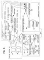
- Figure 3 is a block diagram of the components overall of an embodiment of visual interface system constructed according to the present invention;
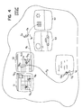
- Figure 4 is a view of a portion of the display system in use;
- Figure 5 is a schematic diagram of a pixel and a designated position on a display screen; and
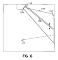
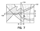
- Figures 6 and 7 are side and front views of a painting being scanned.
- As seen in Figure 1, one example of an interface which enables two
users 10, 12 (or more) to communicate with a computer system 14 (e.g., a personal computer running multiple user applications such as a spreadsheet program, a word processor, a multimedia viewer) includes adisplay system 16 in the form of a rectangular array of raster scannedCRT display screens 18. The information displayed on the screens may be of any kind, including images, visual interfaces provided by graphical operating environments (e.g., Windows), menu driven programs, and command line interfaces. Different display screens may show unrelated information. Display screens may be grouped to display related information. For example, the four screens in the upper right hand corner of the array may show a Windows interface (each of the four screens showing one-fourth of the interface) while the rest of the screens display other images. - In the Figure, each of the users is shown holding a
pointer position - The specific choice and arrangement of buttons or activating mechanisms is a matter of design choice but, whatever, the choice, it is desirable to provide for several different kinds of action by the user, somewhat (but not completely) by analogy to the several different actions that may be taken by a user of a conventional mouse.
- One kind of action is to indicate to the visual interface system whether the user wishes the pointer to be "alive" at all, or not. This may be accomplished by a button which we shall call the "in use" mechanism. By deactivating the in use mechanism, the user may move the pointer around, and gesture, without the motion or gesturing having any effect on the user interface (i.e., with somewhat the same effect as removing one's hand altogether from a conventional mouse). By activating the in use mechanism, the motions of the pointer, and activation of other buttons may be used to interact with the user interface. When the pointer is in use, the designated position (the position at which the pointer is aimed) constitutes an implicit cursor for purpose of taking other actions. The implicit cursor may or may not actually be displayed. Any action that may be taken at a cursor position in a conventional computer system, e.g., a click or double click by a mouse, may be taken with regard to the implicit cursor.
- Another kind of action is to create markers at displayed positions. Markers are merely symbols displayed at positions where the cursor had been at an earlier time and which the user had chosen to mark. We call this the marking mechanism. Markers may take any form or shape on the screen.
- Another kind of action is to indicate when the designated position is intended to match a marker of a previously marked position for the purpose of selecting that marker and taking an action on the marker itself. The action may be to move the marker to another location (e.g., dragging or jumping to the new position) or to take action on a set of markers (e.g., selecting the set). We call this the "marker designation mechanism".
- Another kind of action is to indicate that some event should occur with respect to something (e.g., selection from a menu) that is associated with a marker, a set of markers, or the implicit cursor. This is somewhat analogous to a click or double click of a mouse button. We call the mechanism that enables this action the event mechanism. The event mechanism could be combined with the marker designation mechanism in a single button that is clicked once for marking or marker matching, held down during slewing to indicate a drag action, or double clicked (possibly on an associated menu) to designate an event.
- Each user may use his in-use, event, marking, and marker designation mechanisms independently of, and simultaneously with, other users making use of their mechanisms. The computer system determines immediately which pointer is taking which action with respect to which position or positions on which of the display screens.
- The users may be anywhere within sight of the
display system 16, including at locations which are beyond reach of the display system. For example, the users could be in a room as small as an office or the size of an auditorium. - The visual interface system includes a display control system (not shown in Figure 1) which determines, among other things, the
display screen 18 and the location of the designated position at any time, and the state of the in-use mechanism, the event mechanism, the marking mechanism, and the marker designation mechanism. To make these determinations the display control system must obtain and analyze information which links the motion and control of each pointer with positions on the display screens of the display system. In the example of Figure 1, this is done based on the fact that the display screens emit raster scanned light toward the users. Each screen is raster scanned in successive horizontally painted scan lines so that at any moment in time only a single position on each screen is emitting light toward the pointers. Each pointer has a detector for receiving light from the designated position. By comparing the time at which the light from the designated position is detected at the pointer (we call this the "time of designated position" or TODP") with information about the raster timing of a given screen, it is possible to determine quickly the absolute location of the designated position on the screen without reference to prior designated positions. In the case of multiple screens, it is necessary to know the timing of the raster scan of each screen (when the scanning is unsynchronized among screens) or the global scan timing (when the scanning is synchronized). - Because more than one of the screens may be emitting light at a time, a determination should also be made of which screen bears the designated position. The determination of timing in the pointer depends on use of an optical discriminator (e.g., lens) to discriminate between screens. To convey the screen and timing information to the display control system, each pointer also has a source of emanations which delivers a beam of electromagnetic radiation (e.g., infrared) 28 that is centered on the designated position. The display system has
detectors 30 for this in-bound beam, one detector at each corner of each display. (Other positions for the detectors are also possible.) When the user is aiming the pointer at a designated position, the beam from the pointer covers an area around the designated position which is broad enough to assure its detection by all in-bounddetectors 30 or the display intended. By a monopulse technique described in more detail in Appendix B, the signals from the in-bound detectors are used to determine which of the screens contains the designated position. If only one screen is involved, only a single detector is needed to determine which user is transmitting and to receive timing and other communication signals, but multiple devices provide higher reliability. Monopulse processing may also be used in the pointer to achieve accurate timing information. - The
beam 28 may itself provide (or may be augmented by a narrow beam light source--e.g., a laser designator--to provide) a "passive" indication (a light spot on the screen) of the general aiming direction of the pointer; the beam also may be modulated to provide a communication channel from the pointer to the display system. This channel carries information from the pointer to the display system identifying the pointer, specifying the TODP, and describing the state of the in-use mechanism, the event mechanism, the marking mechanism, and the marker designation mechanism. Alternatively, the channel could be carried on a wire from the pointer to the display system (line 503 in Figures 2 and 3). - Referring also to Figure 4, although not required, the system may display one or more user specific location pointers (e.g., markers or icons in the shape of arrows with different colors and/or shapes) for each user to provide visual feedback while the user is aiming the pointer at either a designated position or an intended position (by "intended position" we mean the position at which the user wishes to aim; by "designated position" me mean the point actually aimed at whether intended or not). The displayed position of each icon or marker is synchronized with the designated position or intended position either automatically or by operation of the marker designation mechanism. In Figure 4, for example, an arrow icon CA of a user A is shown (in one color) pointing at a currently designated position DA; a marker CA-OLD points to a place where user A had previously pointed. A differently colored, pointing finger icon CB of a second user B is simultaneously displayed at a different currently designated position DB. Based on the user's perception of any "error" between the displayed or displayed position and the intended position, the user may move the pointer slightly to correct the error. Computer programs may also be able to assist in making the slight adjustments in certain cases.
- Each user may control the displayed position within a
single display screen 18 by invoking the marking mechanism and the marker designation mechanism to cause the displayed position to be at the designated position. While the user is aiming or re-aiming the pointer, the system may or may not continue to display the old displayed position, or may move the displayed position with the designated position (in the case of a dragging action). If the system does not initially move the displayed position with the designated position, it may do so automatically once the designated position remains temporarily stationary or when the user invokes the marker designation mechanism. The displayed position may subsequently move if the marker designation mechanism is again triggered later on. - The user typically works in two ways with the pointer. In a tracking mode, the user is changing the designated position and may be manipulating the displayed position with respect to the designated position using the marking and marker designation mechanisms. During tracking mode, the system may allow multiple designated positions to be remembered and/or displayed.
- When the designated position reaches the edge of the screen and moves to the adjacent screen during tracking, the displayed icon tracks smoothly to the new screen.
- In the example of Figure 4, user A had begun with the designated position at an old displayed position OA1 (which bears an hour-glass marker), then moved to old displayed position OA2 (also bearing a marker), then to OA3 all within a spreadsheet program displayed across two screens S1, S2. From position OA3 the user had dragged the spreadsheet value in the cell at OA3 toward a frame in a graphics program displayed on screens S3 and S4. The currently designated position DA is slightly offset from the intended position IA.
- During the same period, user B had followed a sequence that included an old displayed position OB1, then OB2, and then had dragged the value in the cell at OB2 to a word processing program running on screen S5.
- With multiple users, any apparent interaction among them may be inferred by underlying software.
- Other commands, for example, commands which correspond to a second or third button on a mouse, could also be implemented.
- Referring to Figure 2,
pointer 20 includes acase 50 holding one ormore batteries 52, abeam source 54, adetector 56 for light received from the designated position on one of the screens, alens 59 for focusing the incoming light onto the detector, activating mechanisms (e.g., buttons) 51, 53, 55, andpointer control circuitry 58 includingdetection circuitry 63 andcommunication circuitry 61. - Referring to Figure 3, the
detector 56 in the pointer has signal processing circuitry and fourpixel values 55 logically arranged in a square. The pointer control circuitry in the pointer includes aclock 62, and amonopulse circuit 64 for receiving signals from thesensors 55 and for delivering corresponding signals indicating the centroid of the arriving light. ATODP element 66 uses clock signals and a signal from the one of theactivation mechanisms TOT element 68 uses clock signals to generate a time of transmission signal. - The communication portion of the pointer circuitry includes a
beam modulator 70 which modulates thebeam source 54 in accordance with the TODP and TOT signals and other information described below. Signals from the activation mechanisms may also be modulated on the beam so that the system can distinguish between and operate differently at times when various ones of the activation mechanisms are being invoked. - Infrared-based signals generated at the
display system sensors 30 are delivered to ademodulator 50 which is part of the detection system (which is part of the display control system 32). The demodulator output passes to three elements where it is analyzed to produce control signals for delivery to thecomputer system 14. Amonopulse element 52 analyzes the sensor outputs, determines centroids of incoming light beams from various pointers, and, from the centroid information, determines which screens are the targets of the pointers. The observed amplitudes at the sensors are fitted to the expected spatial pattern for the user's pointer illumination, conditioned on the designated position. This information is passed to the computer system as screen identities linked to pointer ID's. ATODP element 70 uses the demodulator output signals to recover the TODPs for the various pointers and delivers corresponding signals to a screen position analyzer 72. Analyzer 72 uses the TODPs and raster information from araster synchronizer 74 to derive the designated positions on the screens. - An
activation mechanism analyzer 76 extracts the states of the activation mechanisms from the demodulator output and delivers corresponding activation mechanism signals to thecomputer system 14. -
Computer system 14 includes theusual processor 84,storage 82,memory 80, and screen buffers/drivers 86. A real-time operating system 88 andapplications 90 run on the system. In the case of a single application running on a single screen, the activation mechanism signals and position signals from the interface control system may simply be sent to the computer system much in the way that motion and click signals are sent from a mouse. In the case of multiple screens (and possibly multiple applications) the computer system must include hardware and software which can differentiate among the screen identities, positions, and activation mechanism signals originated from different ones of the pointers. Because the computer system "knows" which application is running in each portion of the display system, the commands from the different pointers can be sorted out and delivered to the appropriate applications. - The pointer measures TODP relative to the
local clock 62 in the pointer to avoid critical timing between TODP and the raster timing. Sending both TODP and TOT data from the pointer to the display system enables precise computation of TODP at the receiver end without requiring a high timing precision (e.g., 10 nsec.) to be maintained over the communication channel. The sensors at the corners of the screens permit redundant demodulation and combining of the received communication signals. Multipath signals may be explicitly allowed or the environment may be engineered to essentially eliminate them. - The frequency of data transmissions from the pointer to the display system may be reduced (from once for each raster line scan) by allowing the pointer to average the estimates of TODP over several (e.g., eight) raster scanned frames. A possible update rate on the order of 10/sec would be reasonable based on a 100-msec. human sensory time. Use of a power of two for the frame-averaging interval would make division by the number of frames a simple shift register operation. The number of frames used for averaging could be dynamically selected to support varying requirements for update rate.
- The actual update interval also may be varied to avoid repeated (periodic) collisions between two pointers whose transmissions happen to collide once. For example, for an 8-frame averaging interval, a pointer could insert a pause of 1 to 3 frame times, chosen pseudo-randomly for each transmission.
- The transmitted TOT and TODP timing signals may be but need not be of full resolution. For a 1024x1024 pixel screen, 20 bits are required to specify the timing of an event to pixel-level precision within a frame. TOT could be restricted to a coarser grid of times corresponding to the four least significant bits being zero. The display control system could measure arrival time of a transmission unambiguously within the time required for four line scans of the screen, so the TOT could be restricted to 256 possible values per frame time, requiring only 8 bits. After completing the multiple frame averaging to estimate TODP, the pointer would transmit its report at a TOT opportunity within the next four-line-scan interval containing the TODP; 12 bits of TODP data would be required to specify when within the four-line-scan interval TODP occurred, while the four line scan interval would supply the remaining eight bits required for TODP just as for TOT. The display system would resolve the pointer's timing and then TODP would be computed.
- The communication signals from the pointer to the display system could use the following format.
bits use explanation 1 - 8 synch acquire data-sampling clock 9 - 16 ID supports 256 pointers 17 - 36 timing data see below 37 - 44 activation status see below 45 - 47 error control see below
The timing data for use with a raster display consists of 8 bits for TOT and 12 bits for TODP. For a static display (see discussion below) the data is 10 bits each for the two equivalent coordinates. Three bits are provided for error checking. Eight bits are provided for carrying status information (on/off) for up to 8 activation mechanisms on the pointer. Optionally, additional bits may be assigned for non-binary activation mechanisms. - To support multiple simultaneous users, the beam from each pointer would be coded for uniqueness possibly using spread spectrum. The display control system would identify the designated positions and sort them out by reading the code, or by using the code as a spread-spectrum signal. Activation mechanisms could be effected using alternate coding of the beam, as could security ID codes.
- Monopulse detection in the pointer overcomes the adverse influence of variations in light intensity associated with the displayed information on the screen. As seen in Figure 5, a designated
location 60 on the surface of ascreen 62 may include several pixels of different intensities. Each pixel may span multiple emanation areas of the screen, e.g., 16 scan lines. As a practical matter, the high resolution in the vicinity of the designated position at the surface of the screen cannot easily or cost effectively be matched at a detector in the pointer. The actual temporal information received at the detector is usually associated with a sequence of blurred line scans modulated by the light intensity pattern at individual local pixels. The effect is further complicated by variation in colors. In the monopulse approach, each of, for example, four detectors receives light from aregion 68 of the display and use generates an intensity signal as an input to a centroid computation. -
- The source in the pointer delivers a broad beam of electromagnetic radiation centered in the direction of the designated position. The breadth of the beam must be enough to assure that it would strike all of the beam sensors for the display of interest regardless of the designated position on that display. Except when the initial designated position falls near the edge of the entire display system, monopulse based on the broad beam from the pointer will give a satisfactory identification of the correct screen. Any error in this process is likely to be similar in magnitude to the initial pointing error made by the user before some visual presentation on the screen (feedback) guides him to the desired position.
- To avoid ambiguities between adjacent screens in the display, the display system may be raster scanned as if it were a single screen, by sending synchronizing pulses from the
raster synchronizer 74 to all screens. Monopulse yields the pointing centroid with an accuracy to approximately 20% of the screen width. Synchronizing the rasters assures that no two individual screens could simultaneously trigger a TODP from a single pointer. Synchronizing the rasters is a straightforward process involving delivery of an external timing signal to all the displays. - While ambiguity in the vertical dimension is unlikely, additional margin may be required to avoid ambiguity on the horizontal sweep because of its higher frequency. Alternate displays could reverse their horizontal sweep directions (displays would form a checkerboard pattern in two dimensions of alternating sweeps). Because the pointer has a specific rotational orientation, the sequence of null-line crossing just before and after TODP uniquely determines whether the sweep was from right to left or from left to right.
- Additional details are found in Appendix C.
- It may be desirable to provide a way to register users (by session or for specific periods of time) to protect against unauthorized access. A security process running on the computer system could authenticate users as a condition to allowing them to use a pointer to interact with the system. In the absence of a software security process, manual registration of users could be used.
- The security process would check that a user is authorized to access the system, and would also convey any restrictions, e.g., user X cannot point to things on screen Y. The security process could be a general function or some or all of the security functions could be integrated directly into the applications.
- When a user appears for the first time, or reappears, the system establishes a pointing session for the user. This includes coordination with the security function to determine the various display permissions to which the user is entitled. If the user disappears for too long an interval, the pointing system terminates the session.
- When a user has been off for less than the session time-out interval and re-invokes the in-use activation mechanism, the system determines which screen has been selected by the user by examining the information received from the display control system. This is done initially using estimates of the newly designated position derived by monopulse processing on the in-bound beam from the pointer, then subsequently from the TODP signals received from the pointer.
- Other embodiments are feasible,
- For example, the display system could be a single screen. A single user could make use of the system. The pointer could be a variant of the commonly used laser pointer. Multiple users could also make use of the system. Spread spectrum or other multiplexing techniques could be used to share the display control system among the various users.
- The system could use information that is being displayed in the vicinity of a designated position to aid the process of identifying the designated position. For example, if the user invokes an activation mechanism while attempting to aim the pointer at a command button of a graphical user interface, and if the aim is only slightly "off" the button, the system may assume that the designated position is "on" the button and so display the pointer there (either waiting for confirmation by the user or implicitly assuming confirmation unless countermanded quickly by the user.)
- A feedback communication channel could be provided from the display system to the pointer to provide control information and a status display. For example, as shown in Figures 2 and 3, in a multi-user game, the pointer could locally display (e.g., on an LED display 501) a score. The feedback channel could be carried by a
wire 502 or by a beam from the display system to the pointer. - The scheme for detecting the designated position may also be applied to static (non-raster scanned) screens by imposing an artificial and temporary pseudo-raster on the screen in the form of a temporal-spatial screen activity that can be sensed at the pointer.
- The pseudo-raster need not scan out individual pixels serially as in a true raster scan. Instead, it could first generate a horizontal line in a vertical scan, then a vertical line in a horizontal scan. This could even be a relatively bright line, because the user will not perceive its presence, or it could be a fixed change in intensity added to each pixel as the line scans. In the latter case, the background would be blocked out by a high-pass filter in the pointer detection circuitry.
- Repetitive scanning could be randomized to avoid scan-to-scan integration in the eyeball but this is not necessary because the appearance of the pseudo-raster would present only a very slight change in the uniform background intensity. The scanning of the vertical and horizontal lines can be effected in under 1 msec. each; the human eyeball cannot detect the event because human cognition requires about 100 msec. The geometry of the optical detectors in the pointer could be selected to optimize performance for the pseudo-raster.
- If the pointer reports the passing of the pseudo-raster each time, then the designated position can be determined. When either a vertical or horizontal line is scanned through the boresight of the pointer, both monopulse channels change sign simultaneously; thus, the channels provide redundant information. This redundancy could be removed by using pseudo-raster lines parallel to the detector null lines, but this would simply make one of the channels inactive.
- Referring to Figures 6 and 7, a similar technique could be used for pointing at designated positions on everyday objects, such as a
painting 102 hanging on a wall. In that case, thepseudo-raster lines projectors -
- The algorithm suggested for the pointer estimation of TODP would work at nearly all rotations about the pointing axis, but it would behave poorly in some small range of angles about an angular orientation corresponding to the raster moving parallel to one of the pointer null lines. A variant algorithm, processing from line-to-line, could handle this case.
- If the pointer algorithm were altered to operate at arbitrary rotation angles about the pointing direction, then this angular rotation could be measured as well. Current-generation software employs "button" actuators on the screen which can be "pushed" with a mouse. With the ability to sense angular rotation of the pointing device about its pointing axis, screen actuators could be programmed which allowed the user to rotate things like knobs and screwheads.
- The in-bound beam could be designed to accept in-bound data from a variety of applications. For example, user responses to questions displayed on a screen could be sent via a modulated electromagnetic beam to the sensors on the display system.
- If quad sensors were substituted for at least one of the sensors placed at the corners of the screens, additional monopulse processing could give lines of bearing to the users. This would enable applications software to interact in interesting ways with the user's motion about the room.
- The pointer enables direct (absolute) designation of features displayed on a screen; alternatively, it enables the description of a trajectory on the screen. Conventional mouse, trackball, and joystick devices, by contrast, provide only relative position corrections, while touch-screen interactions are relatively coarse and awkward. This could be used to trace a route on a map, or to do contour integration, or to write a signature.


Claims (31)
- A natural visual interface which enables a user to communicate by natural human motions, comprising a hand-manipulated pointer configured to permit it to be aimed by line of sight to point at any arbitrary position within the user's field of view, including positions beyond the user's natural reach, and to be swept along any arbitrary path and at any arbitrary speed within the user's natural capability; the interface being characterised in further comprising a detector which is arranged to detect emanations, preferably electromagnetic radiation, more preferably visible light or non-visible infra red radiation, from at least some positions at which the pointer may be aimed, and circuitry which is adapted to identify the locations of positions at which the user is aiming the pointer, whereby the interface enables the user to so communicate with a computer system and to point to a position within his field of view and beyond his reach, to move his hand along any arbitrary path and at any arbitrary speed within the user's natural capability to point to another position, and so on, and to have the circuitry automatically identify the locations of the series of positions to which he has pointed.
- An interface according to Claim 1, characterised in further comprising an event mechanism which enables the user to generate events associated with positions at which the user is aiming the pointer.
- An interface according to Claims 1 or 2, further characterised in that the circuitry is adapted to identify the location within a coordinate system of each position in the series of positions.
- An interface according to any preceding claim, further characterised in that the emanations differ at different positions, and in that the circuitry identifies the location of each position based on differences in the emanations, which differences preferably comprise differences in time of occurrence, most preferably differences in time of occurrence associated with raster scanning of the positions.
- An interface according to any preceding claim, further characterised in that the arbitrary positions to which the pointer may be aimed lie on a surface, preferably a substantially planar surface.
- An interface according to any of Claims 1 to 4, further characterised in that the arbitrary positions to which the pointer may be aimed lie on a pixel image display device.
- An interface according to Claim 6, further characterised in that the display device comprises a raster scanned display.
- An interface according to Claim 6, further characterised in that the display device comprises a static display and a means for imposing a pseudo-raster scan on said static display, preferably by altering the appearance of successive lines shown on the static display.
- An interface according to any preceding claim, further characterised in that the emanations originate at the positions.
- An interface according to any of Claims 1 to 8, further characterised in that the emanations are reflected from the positions.
- An interface according to Claim 10, further characterised in that the reflections are of scanned emanations, preferably directed to a passive everyday object.
- An interface according to any preceding claim, further characterised in that the detector is adapted separately to detect the emanations received at multiple receivers, and in that the interface further comprises a processor for generating a monopulse position signal based on the emanations received at the multiple receivers.
- An interface according to Claim 12, further characterised in that the monopulse position signal is delivered to said circuitry.
- An interface according to Claim 13, characterised in further comprising a wireless communication channel for carrying the monopulse position signal.
- An interface according to Claim 14, further characterised in that the communication channel comprises a coded channel.
- An interface according to Claim 14, further characterised in that the channel comprises a spread-spectrum channel.
- An interface according to any preceding claim, further characterised in that the detector, and/or the circuitry, and/or the event mechanism is (are) attached to the pointer.
- An interface according to Claim 2 or any claim appendant thereto, further characterised in that the events generated by the event mechanism are represented as event signals, delivered to the circuitry, preferably carried by wire, or by electromagnetic radiation.
- An interface according to any preceding claim, characterised in further comprising a second hand-manipulated pointer configured to permit it to be aimed by line of sight to point at any arbitrary position anywhere within a user's field of view, including positions beyond the user's natural reach, and to be swept along any arbitrary path and at any arbitrary speed within the user's natural hand capability, and a second detector which is arranged to detect emanations, preferably electromagnetic radiation, more preferably visible light or non-visible infra red radiation, from at least some of the positions at which the pointer may be aimed, and in that said circuitry is adapted also to identify the location of each position at which the second pointer is aimed.
- An interface according to Claim 19, characterised in further comprising a second event mechanism which enables the user to generate events associated with positions at which the second pointer is aimed.
- An interface according to any preceding claim further characterised in that the arbitrary positions lie on a display system comprising multiple, separately scanned image display surfaces, the interface enabling the user to point to a position on one of the display surfaces, move his hand along any arbitrary path and at any arbitrary speed within the user's natural capability to point to another position on another one of the display surfaces, and so on, and to have the circuitry automatically identify the locations of the series of positions to which he has pointed.
- An interface according to Claim 21, further characterised in that the display surfaces are raster scanned using respective timing signals which are synchronised among the display surfaces.
- An interface according to Claims 21 or 22, characterised in further comprising a display identity detector which is adapted to detect which display bears a position at which the pointer is aimed.
- An interface according to Claim 23, further characterised in that the display identity detector comprises multiple spaced-apart sensors which operatively detect emanations from the pointer, and a monopulse circuit adapted to deliver a signal identifying the display at which the pointer is aimed, based on the emanations detected at the multiple sensors.
- An interface according to Claim 24, further characterised in that the pointer includes a source oriented to deliver electromagnetic radiation to the spaced-apart sensors.
- An interface according to Claims 24 or 25, further characterised in that the monopulse circuit is adapted to generate information associated with the rotational orientation of the pointer.
- An interface according to Claim 21 or any claim appendant thereto, further characterised in that the image display surfaces are pixel image display surfaces arranged in an array.
- An interface according to Claim 21 or any claim appendant thereto, further characterised in that the image display surfaces are rectangular pixel image display surfaces and the sensors are located at the corners of the display surfaces.
- An interface according to both Claims 19 and 21, further characterised in that said circuitry is adapted such that two users may simultaneously point to respective positions on said display surfaces, move their hands respectively along any arbitrary path and at any arbitrary speed within their natural capabilities to point to other positions on other ones of the display surfaces, and so on, and the circuitry can automatically identify the locations of the series of positions to which each of the users has pointed.
- A natural visual interface which enables two users to communicate independently and essentially simultaneously comprising two pointers, one for each user, each pointer configured to permit its user to point to positions in a coordinate system which is within the user's field of view; characterised in that said interface enables the two users to so communicate with a computer, the interface further comprising circuitry which is adapted to identify the absolute location, within the coordinate system, of each position to which each user points, without reference to any previously identified locations, even when the two users are independently and essentially simultaneously pointing to positions within the coordinate system.
- An interface according to Claim 30, characterised in further comprising a communication channel from the circuitry to the pointers, and in that the pointers include an indicator for conveying information to a user based on data received via the communication link.
Priority Applications (1)
| Application Number | Priority Date | Filing Date | Title |
|---|---|---|---|
| EP01203672A EP1168232B1 (en) | 1994-06-09 | 1995-06-09 | Pointing interface |
Applications Claiming Priority (2)
| Application Number | Priority Date | Filing Date | Title |
|---|---|---|---|
| US25707994A | 1994-06-09 | 1994-06-09 | |
| US257079 | 1994-06-09 |
Related Child Applications (1)
| Application Number | Title | Priority Date | Filing Date |
|---|---|---|---|
| EP01203672A Division EP1168232B1 (en) | 1994-06-09 | 1995-06-09 | Pointing interface |
Publications (2)
| Publication Number | Publication Date |
|---|---|
| EP0686935A1 true EP0686935A1 (en) | 1995-12-13 |
| EP0686935B1 EP0686935B1 (en) | 2002-09-18 |
Family
ID=22974787
Family Applications (2)
| Application Number | Title | Priority Date | Filing Date |
|---|---|---|---|
| EP95304024A Expired - Lifetime EP0686935B1 (en) | 1994-06-09 | 1995-06-09 | Pointing interface |
| EP01203672A Expired - Lifetime EP1168232B1 (en) | 1994-06-09 | 1995-06-09 | Pointing interface |
Family Applications After (1)
| Application Number | Title | Priority Date | Filing Date |
|---|---|---|---|
| EP01203672A Expired - Lifetime EP1168232B1 (en) | 1994-06-09 | 1995-06-09 | Pointing interface |
Country Status (4)
| Country | Link |
|---|---|
| US (2) | US5793361A (en) |
| EP (2) | EP0686935B1 (en) |
| AT (2) | ATE261150T1 (en) |
| DE (2) | DE69532662T2 (en) |
Cited By (11)
| Publication number | Priority date | Publication date | Assignee | Title |
|---|---|---|---|---|
| WO1997041502A1 (en) * | 1996-04-27 | 1997-11-06 | Philips Electronics N.V. | Position determination of a laser pointer in a projection display system |
| DE19780412C1 (en) * | 1997-11-14 | 1999-01-21 | Vlg Virtual Laser Games Gmbh | Surface area marking device with electromagnetic ray |
| WO1999026189A1 (en) * | 1997-11-14 | 1999-05-27 | Vlg Virtual Laser Games Gmbh | Device for identifying and marking spots on a surface |
| WO1999026190A1 (en) * | 1997-11-14 | 1999-05-27 | Vlg Virtual Laser Systems Gmbh | System for acquiring and exploiting information |
| DE19880483C1 (en) * | 1998-10-21 | 2000-03-30 | Vlg Virtual Laser Systems Gmbh | Input device for computer with graphical operating surface detects location and/or direction of light beam directed at large screen |
| WO2000031680A1 (en) * | 1998-11-26 | 2000-06-02 | Vlg Virtual Laser Systems Gmbh | Active unit for reproducing large-scale images |
| WO2000031681A1 (en) * | 1998-11-26 | 2000-06-02 | Vlg Virtual Laser Systems Gmbh | Active unit for reproducing large-scale images |
| WO2000038102A1 (en) * | 1998-12-18 | 2000-06-29 | Vlg Virtual Laser Systems Gmbh | Detection and evaluation system for beam pointers |
| US6104380A (en) * | 1997-04-14 | 2000-08-15 | Ricoh Company, Ltd. | Direct pointing apparatus for digital displays |
| US6382798B1 (en) | 1999-05-28 | 2002-05-07 | Universite De Liege | Optical device for projection display system |
| FR2839589A1 (en) * | 2002-05-13 | 2003-11-14 | Yves Guy Reza | Television/video recorder remote control functions having light spot pattern cathode ray screen impinging/detector recognising and logic system movement finding/transmitting electronics mechanism |
Families Citing this family (121)
| Publication number | Priority date | Publication date | Assignee | Title |
|---|---|---|---|---|
| JPH09152307A (en) * | 1995-12-01 | 1997-06-10 | Sega Enterp Ltd | Apparatus and method for detection of coordinates, and game apparatus |
| US20100008551A9 (en) * | 1998-08-18 | 2010-01-14 | Ilya Schiller | Using handwritten information |
| US7268774B2 (en) * | 1998-08-18 | 2007-09-11 | Candledragon, Inc. | Tracking motion of a writing instrument |
| JP4422851B2 (en) * | 1999-03-17 | 2010-02-24 | キヤノン株式会社 | Coordinate input apparatus and method |
| AU3894900A (en) * | 1999-03-17 | 2000-10-16 | Tegrity, Inc. | Method and apparatus for visual pointing and computer control |
| US6535198B1 (en) * | 1999-03-28 | 2003-03-18 | Nongqiang Fan | Remote control for interactive television |
| US7176896B1 (en) * | 1999-08-30 | 2007-02-13 | Anoto Ab | Position code bearing notepad employing activation icons |
| US6346933B1 (en) * | 1999-09-21 | 2002-02-12 | Seiko Epson Corporation | Interactive display presentation system |
| US6710765B1 (en) * | 1999-10-05 | 2004-03-23 | Nippon Telegraph And Telephone Corporation | Input device of 3-D translation and rotation and its method and recording medium |
| US20030061188A1 (en) | 1999-12-23 | 2003-03-27 | Linus Wiebe | General information management system |
| US6900779B1 (en) * | 2000-01-28 | 2005-05-31 | Zheng Jason Geng | Method and apparatus for an interactive volumetric three dimensional display |
| US6633314B1 (en) * | 2000-02-02 | 2003-10-14 | Raja Tuli | Portable high speed internet device integrating cellular telephone and palm top computer |
| US7023572B2 (en) * | 2000-02-02 | 2006-04-04 | Raja Singh Tuli | Portable high speed internet access device |
| US20020030843A1 (en) * | 2000-02-02 | 2002-03-14 | Tuli Raja Singh | Portable high speed internet access device |
| US20020115477A1 (en) * | 2001-02-13 | 2002-08-22 | Raja Singh | Portable high speed internet access device with scrolling |
| US7068381B1 (en) * | 2000-02-02 | 2006-06-27 | Raja Tuli | Portable high speed internet access device |
| US6941382B1 (en) * | 2000-02-07 | 2005-09-06 | Raja Tuli | Portable high speed internet or desktop device |
| US6488583B1 (en) | 2000-04-03 | 2002-12-03 | Mitsubishi Electric Research Laboratories, Inc. | Game playing with individual anonymous laser pointers |
| SG89339A1 (en) * | 2000-07-25 | 2002-06-18 | Koninkl Philips Electronics Nv | Image displaying system and remote control unit for such a system |
| US6707444B1 (en) * | 2000-08-18 | 2004-03-16 | International Business Machines Corporation | Projector and camera arrangement with shared optics and optical marker for use with whiteboard systems |
| US7113175B2 (en) * | 2000-09-26 | 2006-09-26 | Intertact Corporation | Methods and apparatus for supplying power to touch input devices in a touch sensing system |
| US7191211B2 (en) * | 2000-10-03 | 2007-03-13 | Raja Tuli | Portable high speed internet access device priority protocol |
| AUPR061800A0 (en) * | 2000-10-09 | 2000-11-02 | Lake Technology Limited | Authoring system |
| US6930673B2 (en) * | 2000-11-13 | 2005-08-16 | Gtco Calcomp | Collaborative input system |
| US6600478B2 (en) | 2001-01-04 | 2003-07-29 | International Business Machines Corporation | Hand held light actuated point and click device |
| DE10100617A1 (en) * | 2001-01-09 | 2002-07-18 | Siemens Ag | Controllable arrangement with user authentication |
| JP2002222054A (en) * | 2001-01-25 | 2002-08-09 | Nec Corp | Pointing device |
| WO2002077731A1 (en) * | 2001-03-23 | 2002-10-03 | Siemens Aktiengesellschaft | Process control system with image representation system |
| US6929548B2 (en) * | 2002-04-23 | 2005-08-16 | Xiaoling Wang | Apparatus and a method for more realistic shooting video games on computers or similar devices |
| US7084860B1 (en) * | 2001-06-08 | 2006-08-01 | Intertact Corporation | Method and apparatus for a touch sensitive system employing direct sequence spread spectrum (DSSS) technology |
| US6729731B2 (en) * | 2001-06-11 | 2004-05-04 | Info Valley Corporation | Untethered laser pointer for use with computer display |
| JP2003008805A (en) * | 2001-06-26 | 2003-01-10 | Matsushita Electric Ind Co Ltd | Electronic blackboard system |
| US7257255B2 (en) * | 2001-11-21 | 2007-08-14 | Candledragon, Inc. | Capturing hand motion |
| US20030218638A1 (en) * | 2002-02-06 | 2003-11-27 | Stuart Goose | Mobile multimodal user interface combining 3D graphics, location-sensitive speech interaction and tracking technologies |
| US7113169B2 (en) * | 2002-03-18 | 2006-09-26 | The United States Of America As Represented By The Secretary Of The Air Force | Apparatus and method for a multiple-user interface to interactive information displays |
| JP3601819B2 (en) * | 2002-03-18 | 2004-12-15 | 日本電信電話株式会社 | Control device for video viewing device, control method therefor, program and recording medium |
| US20030199324A1 (en) * | 2002-04-23 | 2003-10-23 | Xiaoling Wang | Apparatus and a method for more realistic shooting video games on computers or similar devices using visible or invisible light |
| US20040002369A1 (en) * | 2002-05-06 | 2004-01-01 | Walker Jay S. | Method and apparatus for modifying a game based on results of game plays |
| US20050075166A1 (en) * | 2002-05-14 | 2005-04-07 | Hemstreet Paul A. | Media program with interactive feature |
| US20030222849A1 (en) * | 2002-05-31 | 2003-12-04 | Starkweather Gary K. | Laser-based user input device for electronic projection displays |
| US7952570B2 (en) | 2002-06-08 | 2011-05-31 | Power2B, Inc. | Computer navigation |
| US8176428B2 (en) * | 2002-12-03 | 2012-05-08 | Datawind Net Access Corporation | Portable internet access device back page cache |
| WO2004059560A2 (en) * | 2002-12-23 | 2004-07-15 | The Trustees Of Columbia University In The City Of New York | Systems and methods for tremor cancellation in pointers |
| US7053965B1 (en) * | 2003-06-10 | 2006-05-30 | Fan Nong-Qiang | Remote control for controlling a computer using a screen of a television |
| US7411575B2 (en) | 2003-09-16 | 2008-08-12 | Smart Technologies Ulc | Gesture recognition method and touch system incorporating the same |
| US7298367B2 (en) * | 2003-11-25 | 2007-11-20 | 3M Innovative Properties Company | Light emitting stylus and user input device using same |
| US20050110777A1 (en) * | 2003-11-25 | 2005-05-26 | Geaghan Bernard O. | Light-emitting stylus and user input device using same |
| GB2424269A (en) * | 2004-04-01 | 2006-09-20 | Robert Michael Lipman | Control apparatus |
| US7535456B2 (en) * | 2004-04-30 | 2009-05-19 | Hillcrest Laboratories, Inc. | Methods and devices for removing unintentional movement in 3D pointing devices |
| US8629836B2 (en) | 2004-04-30 | 2014-01-14 | Hillcrest Laboratories, Inc. | 3D pointing devices with orientation compensation and improved usability |
| JP2007535773A (en) | 2004-04-30 | 2007-12-06 | ヒルクレスト・ラボラトリーズ・インコーポレイテッド | Free space pointing device and pointing method |
| EP1596271A1 (en) * | 2004-05-11 | 2005-11-16 | Hitachi Europe S.r.l. | Method for displaying information and information display system |
| WO2005119356A2 (en) | 2004-05-28 | 2005-12-15 | Erik Jan Banning | Interactive direct-pointing system and calibration method |
| US7859523B2 (en) * | 2004-08-10 | 2010-12-28 | Microsoft Corporation | Direct navigation of two-dimensional control using a three-dimensional pointing device |
| NO323926B1 (en) * | 2004-11-12 | 2007-07-23 | New Index As | Visual system and control object and apparatus for use in the system. |
| US8137195B2 (en) | 2004-11-23 | 2012-03-20 | Hillcrest Laboratories, Inc. | Semantic gaming and application transformation |
| US7898505B2 (en) | 2004-12-02 | 2011-03-01 | Hewlett-Packard Development Company, L.P. | Display system |
| KR100711093B1 (en) * | 2005-01-11 | 2007-04-27 | 삼성전기주식회사 | Method and system of direct communication between mobile device and application on display |
| US7852317B2 (en) | 2005-01-12 | 2010-12-14 | Thinkoptics, Inc. | Handheld device for handheld vision based absolute pointing system |
| US9317170B2 (en) | 2005-05-18 | 2016-04-19 | Power2B, Inc. | Interactive devices |
| WO2008111079A2 (en) * | 2007-03-14 | 2008-09-18 | Power2B, Inc. | Interactive devices |
| US10452207B2 (en) | 2005-05-18 | 2019-10-22 | Power2B, Inc. | Displays and information input devices |
| US9569093B2 (en) | 2005-05-18 | 2017-02-14 | Power2B, Inc. | Displays and information input devices |
| JP4417292B2 (en) * | 2005-05-25 | 2010-02-17 | ソフトバンクモバイル株式会社 | Object output method and information processing apparatus |
| US9285897B2 (en) | 2005-07-13 | 2016-03-15 | Ultimate Pointer, L.L.C. | Easily deployable interactive direct-pointing system and calibration method therefor |
| WO2007013063A2 (en) * | 2005-07-26 | 2007-02-01 | Avi Shani | Multidimensional multifunctional computer interface device |
| JP2009508205A (en) | 2005-09-08 | 2009-02-26 | パワー2ビー,インコーポレイティド | Display and information input device |
| US7868874B2 (en) | 2005-11-15 | 2011-01-11 | Synaptics Incorporated | Methods and systems for detecting a position-based attribute of an object using digital codes |
| US8209620B2 (en) | 2006-01-31 | 2012-06-26 | Accenture Global Services Limited | System for storage and navigation of application states and interactions |
| US7599520B2 (en) * | 2005-11-18 | 2009-10-06 | Accenture Global Services Gmbh | Detection of multiple targets on a plane of interest |
| JP4163713B2 (en) * | 2005-12-07 | 2008-10-08 | 株式会社東芝 | Information processing apparatus and touchpad control method |
| KR100800998B1 (en) | 2005-12-24 | 2008-02-11 | 삼성전자주식회사 | Apparatus and method for home network device controlling |
| US20070206120A1 (en) * | 2006-03-03 | 2007-09-06 | Nottage Maurice A | Double screen television |
| WO2007113828A2 (en) * | 2006-04-03 | 2007-10-11 | Power2B Inc. | User interface functionalities |
| JP5138175B2 (en) * | 2006-04-12 | 2013-02-06 | 任天堂株式会社 | Character input program, character input device, character input system, and character input method |
| US7755026B2 (en) | 2006-05-04 | 2010-07-13 | CandleDragon Inc. | Generating signals representative of sensed light that is associated with writing being done by a user |
| US20080052750A1 (en) * | 2006-08-28 | 2008-02-28 | Anders Grunnet-Jepsen | Direct-point on-demand information exchanges |
| US8913003B2 (en) | 2006-07-17 | 2014-12-16 | Thinkoptics, Inc. | Free-space multi-dimensional absolute pointer using a projection marker system |
| US20080018591A1 (en) * | 2006-07-20 | 2008-01-24 | Arkady Pittel | User Interfacing |
| US20080117339A1 (en) * | 2006-11-20 | 2008-05-22 | Comcast Cable Holdings, Llc | Remote control based content control |
| US8089455B1 (en) | 2006-11-28 | 2012-01-03 | Wieder James W | Remote control with a single control button |
| JP5191119B2 (en) * | 2006-12-06 | 2013-04-24 | 株式会社ジャパンディスプレイウェスト | Display device, display device control method, and program |
| US20080166175A1 (en) * | 2007-01-05 | 2008-07-10 | Candledragon, Inc. | Holding and Using an Electronic Pen and Paper |
| EP2137717A4 (en) | 2007-03-14 | 2012-01-25 | Power2B Inc | Displays and information input devices |
| US9176598B2 (en) | 2007-05-08 | 2015-11-03 | Thinkoptics, Inc. | Free-space multi-dimensional absolute pointer with improved performance |
| WO2008156453A1 (en) * | 2007-06-20 | 2008-12-24 | Thomson Licensing | Laser pointer for an interactive display |
| WO2008156457A1 (en) * | 2007-06-20 | 2008-12-24 | Thomson Licensing | Interactive display with camera feedback |
| EP2208354A4 (en) * | 2007-10-10 | 2010-12-22 | Gerard Dirk Smits | Image projector with reflected light tracking |
| US20090309834A1 (en) * | 2008-06-16 | 2009-12-17 | Upmc | Laser Pointer Mouse |
| US8227742B2 (en) | 2008-08-07 | 2012-07-24 | Rapt Ip Limited | Optical control system with modulated emitters |
| KR101589163B1 (en) * | 2008-12-11 | 2016-01-28 | 삼성전자주식회사 | Inputting Method And System For Electro-Device |
| US20110063522A1 (en) * | 2009-09-14 | 2011-03-17 | Jeyhan Karaoguz | System and method for generating television screen pointing information using an external receiver |
| US8499257B2 (en) * | 2010-02-09 | 2013-07-30 | Microsoft Corporation | Handles interactions for human—computer interface |
| EP2625845B1 (en) | 2010-10-04 | 2021-03-03 | Gerard Dirk Smits | System and method for 3-d projection and enhancements for interactivity |
| KR101807622B1 (en) * | 2010-12-27 | 2017-12-11 | 삼성전자주식회사 | Display apparatus, remote controller and method for controlling applied thereto |
| JP5783004B2 (en) * | 2011-11-17 | 2015-09-24 | セイコーエプソン株式会社 | Position detection system and position detection method |
| US8730210B2 (en) * | 2011-10-19 | 2014-05-20 | Microvision, Inc. | Multipoint source detection in a scanned beam display |
| US8711370B1 (en) | 2012-10-04 | 2014-04-29 | Gerard Dirk Smits | Scanning optical positioning system with spatially triangulating receivers |
| US8971568B1 (en) | 2012-10-08 | 2015-03-03 | Gerard Dirk Smits | Method, apparatus, and manufacture for document writing and annotation with virtual ink |
| US9048779B2 (en) | 2013-04-19 | 2015-06-02 | Randall Lee Szarzynski | Multi-dimensional positioning of an object |
| KR102220825B1 (en) * | 2013-09-05 | 2021-03-02 | 삼성전자주식회사 | Electronic apparatus and method for outputting a content |
| US9810913B2 (en) | 2014-03-28 | 2017-11-07 | Gerard Dirk Smits | Smart head-mounted projection system |
| US9377533B2 (en) | 2014-08-11 | 2016-06-28 | Gerard Dirk Smits | Three-dimensional triangulation and time-of-flight based tracking systems and methods |
| US9557832B2 (en) | 2014-08-25 | 2017-01-31 | Getac Technology Corporation | Cursor control apparatus and cursor control method thereof |
| US9405387B2 (en) * | 2014-09-17 | 2016-08-02 | Getac Technology Corporation | Cursor control apparatus and cursor control method thereof |
| WO2016058847A1 (en) | 2014-10-13 | 2016-04-21 | Thomson Licensing | Method for controlling the displaying of text for aiding reading on a display device, and apparatus adapted for carrying out the method, computer program, and computer readable storage medium |
| US10043282B2 (en) | 2015-04-13 | 2018-08-07 | Gerard Dirk Smits | Machine vision for ego-motion, segmenting, and classifying objects |
| US9753126B2 (en) | 2015-12-18 | 2017-09-05 | Gerard Dirk Smits | Real time position sensing of objects |
| US9813673B2 (en) | 2016-01-20 | 2017-11-07 | Gerard Dirk Smits | Holographic video capture and telepresence system |
| USD795871S1 (en) * | 2016-06-01 | 2017-08-29 | Microsoft Corporation | Illuminated augmented reality input device |
| USD795256S1 (en) * | 2016-06-01 | 2017-08-22 | Microsoft Corporation | Augmented reality input device |
| USD795870S1 (en) * | 2016-06-01 | 2017-08-29 | Microsoft Corporation | Augmented reality input device |
| US10067230B2 (en) | 2016-10-31 | 2018-09-04 | Gerard Dirk Smits | Fast scanning LIDAR with dynamic voxel probing |
| WO2018125850A1 (en) | 2016-12-27 | 2018-07-05 | Gerard Dirk Smits | Systems and methods for machine perception |
| WO2018209096A2 (en) | 2017-05-10 | 2018-11-15 | Gerard Dirk Smits | Scan mirror systems and methods |
| WO2019079750A1 (en) | 2017-10-19 | 2019-04-25 | Gerard Dirk Smits | Methods and systems for navigating a vehicle including a novel fiducial marker system |
| WO2019148214A1 (en) | 2018-01-29 | 2019-08-01 | Gerard Dirk Smits | Hyper-resolved, high bandwidth scanned lidar systems |
| WO2019236588A1 (en) | 2018-06-04 | 2019-12-12 | The Research Foundation For The State University Of New York | System and method associated with expedient determination of location of one or more object(s) within a bounded perimeter of 3d space based on mapping and navigation to a precise poi destination using a smart laser pointer device |
| US11273367B1 (en) * | 2019-09-24 | 2022-03-15 | Wayne Hughes Beckett | Non-CRT pointing device |
| WO2021174227A1 (en) | 2020-02-27 | 2021-09-02 | Gerard Dirk Smits | High resolution scanning of remote objects with fast sweeping laser beams and signal recovery by twitchy pixel array |
| US20220317782A1 (en) * | 2021-04-01 | 2022-10-06 | Universal City Studios Llc | Interactive environment with portable devices |
Citations (2)
| Publication number | Priority date | Publication date | Assignee | Title |
|---|---|---|---|---|
| WO1992009062A1 (en) * | 1990-11-09 | 1992-05-29 | Proxima Corporation | Method and apparatus for calibrating an optical computer input system |
| EP0515015A2 (en) * | 1991-05-10 | 1992-11-25 | nVIEW CORPORATION | Method and apparatus for interacting with a computer generated projected image |
Family Cites Families (13)
| Publication number | Priority date | Publication date | Assignee | Title |
|---|---|---|---|---|
| JPS59212945A (en) * | 1983-05-19 | 1984-12-01 | Nippon Telegr & Teleph Corp <Ntt> | Remote indication input device |
| US4591841A (en) * | 1983-11-01 | 1986-05-27 | Wisconsin Alumni Research Foundation | Long range optical pointing for video screens |
| US4884068A (en) * | 1986-09-12 | 1989-11-28 | Matheny Stephen E | Multiple display system |
| CA1334684C (en) * | 1987-10-14 | 1995-03-07 | Wang Laboratories, Inc. | Computer input device using an orientation sensor |
| US4814552A (en) * | 1987-12-02 | 1989-03-21 | Xerox Corporation | Ultrasound position input device |
| US5045843B1 (en) * | 1988-12-06 | 1996-07-16 | Selectech Ltd | Optical pointing device |
| DE4000518A1 (en) * | 1989-03-17 | 1990-09-20 | Mutoh Ind Ltd | Input unit for CAD system with digitising tablet - has screen on tablet displaying cursor and right-angled reference line for ease of operation |
| US5504501A (en) * | 1989-11-07 | 1996-04-02 | Proxima Corporation | Optical input arrangement and method of using same |
| AU8096391A (en) * | 1990-05-23 | 1991-12-10 | Brian M. Mann | Computer aided design system utilizing large surface image |
| JPH0435365A (en) * | 1990-05-28 | 1992-02-06 | Matsushita Electric Ind Co Ltd | Remote control device |
| US5341155A (en) * | 1990-11-02 | 1994-08-23 | Xerox Corporation | Method for correction of position location indicator for a large area display system |
| US5420607A (en) * | 1992-09-02 | 1995-05-30 | Miller; Robert F. | Electronic paintbrush and color palette |
| JPH06222884A (en) * | 1992-12-16 | 1994-08-12 | Xerox Corp | Method for usage of position input device |
-
1995
- 1995-06-09 AT AT01203672T patent/ATE261150T1/en not_active IP Right Cessation
- 1995-06-09 EP EP95304024A patent/EP0686935B1/en not_active Expired - Lifetime
- 1995-06-09 DE DE69532662T patent/DE69532662T2/en not_active Expired - Lifetime
- 1995-06-09 EP EP01203672A patent/EP1168232B1/en not_active Expired - Lifetime
- 1995-06-09 DE DE69528212T patent/DE69528212T2/en not_active Expired - Lifetime
- 1995-06-09 AT AT95304024T patent/ATE224567T1/en not_active IP Right Cessation
-
1996
- 1996-12-09 US US08/762,531 patent/US5793361A/en not_active Expired - Lifetime
-
1998
- 1998-02-25 US US09/030,646 patent/US6404416B1/en not_active Expired - Lifetime
Patent Citations (2)
| Publication number | Priority date | Publication date | Assignee | Title |
|---|---|---|---|---|
| WO1992009062A1 (en) * | 1990-11-09 | 1992-05-29 | Proxima Corporation | Method and apparatus for calibrating an optical computer input system |
| EP0515015A2 (en) * | 1991-05-10 | 1992-11-25 | nVIEW CORPORATION | Method and apparatus for interacting with a computer generated projected image |
Cited By (12)
| Publication number | Priority date | Publication date | Assignee | Title |
|---|---|---|---|---|
| WO1997041502A1 (en) * | 1996-04-27 | 1997-11-06 | Philips Electronics N.V. | Position determination of a laser pointer in a projection display system |
| US6104380A (en) * | 1997-04-14 | 2000-08-15 | Ricoh Company, Ltd. | Direct pointing apparatus for digital displays |
| DE19816147B4 (en) * | 1997-04-14 | 2005-10-20 | Ricoh Kk | Cursor control system |
| DE19780412C1 (en) * | 1997-11-14 | 1999-01-21 | Vlg Virtual Laser Games Gmbh | Surface area marking device with electromagnetic ray |
| WO1999026189A1 (en) * | 1997-11-14 | 1999-05-27 | Vlg Virtual Laser Games Gmbh | Device for identifying and marking spots on a surface |
| WO1999026190A1 (en) * | 1997-11-14 | 1999-05-27 | Vlg Virtual Laser Systems Gmbh | System for acquiring and exploiting information |
| DE19880483C1 (en) * | 1998-10-21 | 2000-03-30 | Vlg Virtual Laser Systems Gmbh | Input device for computer with graphical operating surface detects location and/or direction of light beam directed at large screen |
| WO2000031680A1 (en) * | 1998-11-26 | 2000-06-02 | Vlg Virtual Laser Systems Gmbh | Active unit for reproducing large-scale images |
| WO2000031681A1 (en) * | 1998-11-26 | 2000-06-02 | Vlg Virtual Laser Systems Gmbh | Active unit for reproducing large-scale images |
| WO2000038102A1 (en) * | 1998-12-18 | 2000-06-29 | Vlg Virtual Laser Systems Gmbh | Detection and evaluation system for beam pointers |
| US6382798B1 (en) | 1999-05-28 | 2002-05-07 | Universite De Liege | Optical device for projection display system |
| FR2839589A1 (en) * | 2002-05-13 | 2003-11-14 | Yves Guy Reza | Television/video recorder remote control functions having light spot pattern cathode ray screen impinging/detector recognising and logic system movement finding/transmitting electronics mechanism |
Also Published As
| Publication number | Publication date |
|---|---|
| EP1168232A1 (en) | 2002-01-02 |
| EP1168232B1 (en) | 2004-03-03 |
| ATE224567T1 (en) | 2002-10-15 |
| US5793361A (en) | 1998-08-11 |
| US6404416B1 (en) | 2002-06-11 |
| EP0686935B1 (en) | 2002-09-18 |
| DE69532662D1 (en) | 2004-04-08 |
| DE69532662T2 (en) | 2005-02-10 |
| ATE261150T1 (en) | 2004-03-15 |
| DE69528212T2 (en) | 2003-04-24 |
| DE69528212D1 (en) | 2002-10-24 |
Similar Documents
| Publication | Publication Date | Title |
|---|---|---|
| EP0686935A1 (en) | Pointing interface | |
| US10191559B2 (en) | Computer interface for manipulated objects with an absolute pose detection component | |
| CA2378154C (en) | Computer presentation system and method with optical tracking of wireless pointer | |
| EP3508812B1 (en) | Object position and orientation detection system | |
| EP1704465B1 (en) | Method and apparatus for light input device | |
| US7257255B2 (en) | Capturing hand motion | |
| US9430059B2 (en) | Multi-user pointing apparaus and method | |
| EP2396710A1 (en) | Touch pointers disambiguation by active display feedback | |
| CN101911162A (en) | Input device for a scanned beam display | |
| Cavens et al. | Interacting with the big screen: pointers to ponder | |
| US20030210230A1 (en) | Invisible beam pointer system | |
| US20230349693A1 (en) | System and method for generating input data from pose estimates of a manipulated object by using light data and relative motion data | |
| EP3985491A1 (en) | Control method for touchless gesture control | |
| WO2000058933A1 (en) | Method and apparatus for visual pointing and computer control | |
| RU2429549C1 (en) | Method for multi-user remote control of computer for graphic applications |
Legal Events
| Date | Code | Title | Description |
|---|---|---|---|
| PUAI | Public reference made under article 153(3) epc to a published international application that has entered the european phase |
Free format text: ORIGINAL CODE: 0009012 |
|
| AK | Designated contracting states |
Kind code of ref document: A1 Designated state(s): AT BE CH DE DK ES FR GB GR IE IT LI LU MC NL PT SE |
|
| 17P | Request for examination filed |
Effective date: 19960613 |
|
| 17Q | First examination report despatched |
Effective date: 19990308 |
|
| GRAG | Despatch of communication of intention to grant |
Free format text: ORIGINAL CODE: EPIDOS AGRA |
|
| GRAG | Despatch of communication of intention to grant |
Free format text: ORIGINAL CODE: EPIDOS AGRA |
|
| GRAH | Despatch of communication of intention to grant a patent |
Free format text: ORIGINAL CODE: EPIDOS IGRA |
|
| GRAH | Despatch of communication of intention to grant a patent |
Free format text: ORIGINAL CODE: EPIDOS IGRA |
|
| GRAA | (expected) grant |
Free format text: ORIGINAL CODE: 0009210 |
|
| AK | Designated contracting states |
Kind code of ref document: B1 Designated state(s): AT BE CH DE DK ES FR GB GR IE IT LI LU MC NL PT SE |
|
| PG25 | Lapsed in a contracting state [announced via postgrant information from national office to epo] |
Ref country code: NL Free format text: LAPSE BECAUSE OF FAILURE TO SUBMIT A TRANSLATION OF THE DESCRIPTION OR TO PAY THE FEE WITHIN THE PRESCRIBED TIME-LIMIT Effective date: 20020918 Ref country code: LI Free format text: LAPSE BECAUSE OF FAILURE TO SUBMIT A TRANSLATION OF THE DESCRIPTION OR TO PAY THE FEE WITHIN THE PRESCRIBED TIME-LIMIT Effective date: 20020918 Ref country code: IT Free format text: LAPSE BECAUSE OF FAILURE TO SUBMIT A TRANSLATION OF THE DESCRIPTION OR TO PAY THE FEE WITHIN THE PRE;WARNING: LAPSES OF ITALIAN PATENTS WITH EFFECTIVE DATE BEFORE 2007 MAY HAVE OCCURRED AT ANY TIME BEFORE 2007. THE CORRECT EFFECTIVE DATE MAY BE DIFFERENT FROM THE ONE RECORDED.SCRIBED TIME-LIMIT Effective date: 20020918 Ref country code: GR Free format text: LAPSE BECAUSE OF FAILURE TO SUBMIT A TRANSLATION OF THE DESCRIPTION OR TO PAY THE FEE WITHIN THE PRESCRIBED TIME-LIMIT Effective date: 20020918 Ref country code: CH Free format text: LAPSE BECAUSE OF FAILURE TO SUBMIT A TRANSLATION OF THE DESCRIPTION OR TO PAY THE FEE WITHIN THE PRESCRIBED TIME-LIMIT Effective date: 20020918 Ref country code: BE Free format text: LAPSE BECAUSE OF FAILURE TO SUBMIT A TRANSLATION OF THE DESCRIPTION OR TO PAY THE FEE WITHIN THE PRESCRIBED TIME-LIMIT Effective date: 20020918 Ref country code: AT Free format text: LAPSE BECAUSE OF FAILURE TO SUBMIT A TRANSLATION OF THE DESCRIPTION OR TO PAY THE FEE WITHIN THE PRESCRIBED TIME-LIMIT Effective date: 20020918 |
|
| REF | Corresponds to: |
Ref document number: 224567 Country of ref document: AT Date of ref document: 20021015 Kind code of ref document: T |
|
| REG | Reference to a national code |
Ref country code: GB Ref legal event code: FG4D |
|
| REG | Reference to a national code |
Ref country code: CH Ref legal event code: EP |
|
| REG | Reference to a national code |
Ref country code: IE Ref legal event code: FG4D |
|
| REF | Corresponds to: |
Ref document number: 69528212 Country of ref document: DE Date of ref document: 20021024 |
|
| PG25 | Lapsed in a contracting state [announced via postgrant information from national office to epo] |
Ref country code: SE Free format text: LAPSE BECAUSE OF FAILURE TO SUBMIT A TRANSLATION OF THE DESCRIPTION OR TO PAY THE FEE WITHIN THE PRESCRIBED TIME-LIMIT Effective date: 20021218 Ref country code: PT Free format text: LAPSE BECAUSE OF FAILURE TO SUBMIT A TRANSLATION OF THE DESCRIPTION OR TO PAY THE FEE WITHIN THE PRESCRIBED TIME-LIMIT Effective date: 20021218 Ref country code: DK Free format text: LAPSE BECAUSE OF FAILURE TO SUBMIT A TRANSLATION OF THE DESCRIPTION OR TO PAY THE FEE WITHIN THE PRESCRIBED TIME-LIMIT Effective date: 20021218 |
|
| NLV1 | Nl: lapsed or annulled due to failure to fulfill the requirements of art. 29p and 29m of the patents act | ||
| PG25 | Lapsed in a contracting state [announced via postgrant information from national office to epo] |
Ref country code: ES Free format text: LAPSE BECAUSE OF FAILURE TO SUBMIT A TRANSLATION OF THE DESCRIPTION OR TO PAY THE FEE WITHIN THE PRESCRIBED TIME-LIMIT Effective date: 20030328 |
|
| ET | Fr: translation filed | ||
| REG | Reference to a national code |
Ref country code: CH Ref legal event code: PL |
|
| PG25 | Lapsed in a contracting state [announced via postgrant information from national office to epo] |
Ref country code: LU Free format text: LAPSE BECAUSE OF NON-PAYMENT OF DUE FEES Effective date: 20030609 |
|
| PG25 | Lapsed in a contracting state [announced via postgrant information from national office to epo] |
Ref country code: MC Free format text: LAPSE BECAUSE OF NON-PAYMENT OF DUE FEES Effective date: 20030630 |
|
| PLBE | No opposition filed within time limit |
Free format text: ORIGINAL CODE: 0009261 |
|
| STAA | Information on the status of an ep patent application or granted ep patent |
Free format text: STATUS: NO OPPOSITION FILED WITHIN TIME LIMIT |
|
| 26N | No opposition filed |
Effective date: 20030619 |
|
| PGFP | Annual fee paid to national office [announced via postgrant information from national office to epo] |
Ref country code: IE Payment date: 20140627 Year of fee payment: 20 Ref country code: GB Payment date: 20140627 Year of fee payment: 20 |
|
| PGFP | Annual fee paid to national office [announced via postgrant information from national office to epo] |
Ref country code: DE Payment date: 20140627 Year of fee payment: 20 |
|
| PGFP | Annual fee paid to national office [announced via postgrant information from national office to epo] |
Ref country code: FR Payment date: 20140617 Year of fee payment: 20 |
|
| REG | Reference to a national code |
Ref country code: DE Ref legal event code: R071 Ref document number: 69528212 Country of ref document: DE |
|
| REG | Reference to a national code |
Ref country code: GB Ref legal event code: PE20 Expiry date: 20150608 |
|
| REG | Reference to a national code |
Ref country code: IE Ref legal event code: MK9A |
|
| PG25 | Lapsed in a contracting state [announced via postgrant information from national office to epo] |
Ref country code: GB Free format text: LAPSE BECAUSE OF EXPIRATION OF PROTECTION Effective date: 20150608 |
|
| PG25 | Lapsed in a contracting state [announced via postgrant information from national office to epo] |
Ref country code: IE Free format text: LAPSE BECAUSE OF EXPIRATION OF PROTECTION Effective date: 20150609 |