EP0689805B1 - Bistable luminal graft endoprostheses - Google Patents
Bistable luminal graft endoprostheses Download PDFInfo
- Publication number
- EP0689805B1 EP0689805B1 EP95109038A EP95109038A EP0689805B1 EP 0689805 B1 EP0689805 B1 EP 0689805B1 EP 95109038 A EP95109038 A EP 95109038A EP 95109038 A EP95109038 A EP 95109038A EP 0689805 B1 EP0689805 B1 EP 0689805B1
- Authority
- EP
- European Patent Office
- Prior art keywords
- graft
- stent
- graft member
- expanded
- polymeric material
- Prior art date
- Legal status (The legal status is an assumption and is not a legal conclusion. Google has not performed a legal analysis and makes no representation as to the accuracy of the status listed.)
- Expired - Lifetime
Links
Images

Classifications
-
- A—HUMAN NECESSITIES
- A61—MEDICAL OR VETERINARY SCIENCE; HYGIENE
- A61F—FILTERS IMPLANTABLE INTO BLOOD VESSELS; PROSTHESES; DEVICES PROVIDING PATENCY TO, OR PREVENTING COLLAPSING OF, TUBULAR STRUCTURES OF THE BODY, e.g. STENTS; ORTHOPAEDIC, NURSING OR CONTRACEPTIVE DEVICES; FOMENTATION; TREATMENT OR PROTECTION OF EYES OR EARS; BANDAGES, DRESSINGS OR ABSORBENT PADS; FIRST-AID KITS
- A61F2/00—Filters implantable into blood vessels; Prostheses, i.e. artificial substitutes or replacements for parts of the body; Appliances for connecting them with the body; Devices providing patency to, or preventing collapsing of, tubular structures of the body, e.g. stents
- A61F2/02—Prostheses implantable into the body
- A61F2/04—Hollow or tubular parts of organs, e.g. bladders, tracheae, bronchi or bile ducts
- A61F2/06—Blood vessels
- A61F2/07—Stent-grafts
-
- A—HUMAN NECESSITIES
- A61—MEDICAL OR VETERINARY SCIENCE; HYGIENE
- A61F—FILTERS IMPLANTABLE INTO BLOOD VESSELS; PROSTHESES; DEVICES PROVIDING PATENCY TO, OR PREVENTING COLLAPSING OF, TUBULAR STRUCTURES OF THE BODY, e.g. STENTS; ORTHOPAEDIC, NURSING OR CONTRACEPTIVE DEVICES; FOMENTATION; TREATMENT OR PROTECTION OF EYES OR EARS; BANDAGES, DRESSINGS OR ABSORBENT PADS; FIRST-AID KITS
- A61F2/00—Filters implantable into blood vessels; Prostheses, i.e. artificial substitutes or replacements for parts of the body; Appliances for connecting them with the body; Devices providing patency to, or preventing collapsing of, tubular structures of the body, e.g. stents
- A61F2/82—Devices providing patency to, or preventing collapsing of, tubular structures of the body, e.g. stents
- A61F2/86—Stents in a form characterised by the wire-like elements; Stents in the form characterised by a net-like or mesh-like structure
- A61F2/88—Stents in a form characterised by the wire-like elements; Stents in the form characterised by a net-like or mesh-like structure the wire-like elements formed as helical or spiral coils
-
- A—HUMAN NECESSITIES
- A61—MEDICAL OR VETERINARY SCIENCE; HYGIENE
- A61F—FILTERS IMPLANTABLE INTO BLOOD VESSELS; PROSTHESES; DEVICES PROVIDING PATENCY TO, OR PREVENTING COLLAPSING OF, TUBULAR STRUCTURES OF THE BODY, e.g. STENTS; ORTHOPAEDIC, NURSING OR CONTRACEPTIVE DEVICES; FOMENTATION; TREATMENT OR PROTECTION OF EYES OR EARS; BANDAGES, DRESSINGS OR ABSORBENT PADS; FIRST-AID KITS
- A61F2/00—Filters implantable into blood vessels; Prostheses, i.e. artificial substitutes or replacements for parts of the body; Appliances for connecting them with the body; Devices providing patency to, or preventing collapsing of, tubular structures of the body, e.g. stents
- A61F2/95—Instruments specially adapted for placement or removal of stents or stent-grafts
- A61F2/958—Inflatable balloons for placing stents or stent-grafts
-
- A—HUMAN NECESSITIES
- A61—MEDICAL OR VETERINARY SCIENCE; HYGIENE
- A61L—METHODS OR APPARATUS FOR STERILISING MATERIALS OR OBJECTS IN GENERAL; DISINFECTION, STERILISATION OR DEODORISATION OF AIR; CHEMICAL ASPECTS OF BANDAGES, DRESSINGS, ABSORBENT PADS OR SURGICAL ARTICLES; MATERIALS FOR BANDAGES, DRESSINGS, ABSORBENT PADS OR SURGICAL ARTICLES
- A61L31/00—Materials for other surgical articles, e.g. stents, stent-grafts, shunts, surgical drapes, guide wires, materials for adhesion prevention, occluding devices, surgical gloves, tissue fixation devices
- A61L31/04—Macromolecular materials
-
- A—HUMAN NECESSITIES
- A61—MEDICAL OR VETERINARY SCIENCE; HYGIENE
- A61F—FILTERS IMPLANTABLE INTO BLOOD VESSELS; PROSTHESES; DEVICES PROVIDING PATENCY TO, OR PREVENTING COLLAPSING OF, TUBULAR STRUCTURES OF THE BODY, e.g. STENTS; ORTHOPAEDIC, NURSING OR CONTRACEPTIVE DEVICES; FOMENTATION; TREATMENT OR PROTECTION OF EYES OR EARS; BANDAGES, DRESSINGS OR ABSORBENT PADS; FIRST-AID KITS
- A61F2/00—Filters implantable into blood vessels; Prostheses, i.e. artificial substitutes or replacements for parts of the body; Appliances for connecting them with the body; Devices providing patency to, or preventing collapsing of, tubular structures of the body, e.g. stents
- A61F2/82—Devices providing patency to, or preventing collapsing of, tubular structures of the body, e.g. stents
- A61F2/86—Stents in a form characterised by the wire-like elements; Stents in the form characterised by a net-like or mesh-like structure
- A61F2/89—Stents in a form characterised by the wire-like elements; Stents in the form characterised by a net-like or mesh-like structure the wire-like elements comprising two or more adjacent rings flexibly connected by separate members
-
- A—HUMAN NECESSITIES
- A61—MEDICAL OR VETERINARY SCIENCE; HYGIENE
- A61F—FILTERS IMPLANTABLE INTO BLOOD VESSELS; PROSTHESES; DEVICES PROVIDING PATENCY TO, OR PREVENTING COLLAPSING OF, TUBULAR STRUCTURES OF THE BODY, e.g. STENTS; ORTHOPAEDIC, NURSING OR CONTRACEPTIVE DEVICES; FOMENTATION; TREATMENT OR PROTECTION OF EYES OR EARS; BANDAGES, DRESSINGS OR ABSORBENT PADS; FIRST-AID KITS
- A61F2/00—Filters implantable into blood vessels; Prostheses, i.e. artificial substitutes or replacements for parts of the body; Appliances for connecting them with the body; Devices providing patency to, or preventing collapsing of, tubular structures of the body, e.g. stents
- A61F2/02—Prostheses implantable into the body
- A61F2/04—Hollow or tubular parts of organs, e.g. bladders, tracheae, bronchi or bile ducts
- A61F2/06—Blood vessels
- A61F2/07—Stent-grafts
- A61F2002/072—Encapsulated stents, e.g. wire or whole stent embedded in lining
-
- A—HUMAN NECESSITIES
- A61—MEDICAL OR VETERINARY SCIENCE; HYGIENE
- A61F—FILTERS IMPLANTABLE INTO BLOOD VESSELS; PROSTHESES; DEVICES PROVIDING PATENCY TO, OR PREVENTING COLLAPSING OF, TUBULAR STRUCTURES OF THE BODY, e.g. STENTS; ORTHOPAEDIC, NURSING OR CONTRACEPTIVE DEVICES; FOMENTATION; TREATMENT OR PROTECTION OF EYES OR EARS; BANDAGES, DRESSINGS OR ABSORBENT PADS; FIRST-AID KITS
- A61F2/00—Filters implantable into blood vessels; Prostheses, i.e. artificial substitutes or replacements for parts of the body; Appliances for connecting them with the body; Devices providing patency to, or preventing collapsing of, tubular structures of the body, e.g. stents
- A61F2/02—Prostheses implantable into the body
- A61F2/04—Hollow or tubular parts of organs, e.g. bladders, tracheae, bronchi or bile ducts
- A61F2/06—Blood vessels
- A61F2/07—Stent-grafts
- A61F2002/075—Stent-grafts the stent being loosely attached to the graft material, e.g. by stitching
-
- A—HUMAN NECESSITIES
- A61—MEDICAL OR VETERINARY SCIENCE; HYGIENE
- A61F—FILTERS IMPLANTABLE INTO BLOOD VESSELS; PROSTHESES; DEVICES PROVIDING PATENCY TO, OR PREVENTING COLLAPSING OF, TUBULAR STRUCTURES OF THE BODY, e.g. STENTS; ORTHOPAEDIC, NURSING OR CONTRACEPTIVE DEVICES; FOMENTATION; TREATMENT OR PROTECTION OF EYES OR EARS; BANDAGES, DRESSINGS OR ABSORBENT PADS; FIRST-AID KITS
- A61F2/00—Filters implantable into blood vessels; Prostheses, i.e. artificial substitutes or replacements for parts of the body; Appliances for connecting them with the body; Devices providing patency to, or preventing collapsing of, tubular structures of the body, e.g. stents
- A61F2/82—Devices providing patency to, or preventing collapsing of, tubular structures of the body, e.g. stents
- A61F2002/823—Stents, different from stent-grafts, adapted to cover an aneurysm
-
- A—HUMAN NECESSITIES
- A61—MEDICAL OR VETERINARY SCIENCE; HYGIENE
- A61F—FILTERS IMPLANTABLE INTO BLOOD VESSELS; PROSTHESES; DEVICES PROVIDING PATENCY TO, OR PREVENTING COLLAPSING OF, TUBULAR STRUCTURES OF THE BODY, e.g. STENTS; ORTHOPAEDIC, NURSING OR CONTRACEPTIVE DEVICES; FOMENTATION; TREATMENT OR PROTECTION OF EYES OR EARS; BANDAGES, DRESSINGS OR ABSORBENT PADS; FIRST-AID KITS
- A61F2220/00—Fixations or connections for prostheses classified in groups A61F2/00 - A61F2/26 or A61F2/82 or A61F9/00 or A61F11/00 or subgroups thereof
- A61F2220/0025—Connections or couplings between prosthetic parts, e.g. between modular parts; Connecting elements
- A61F2220/005—Connections or couplings between prosthetic parts, e.g. between modular parts; Connecting elements using adhesives
Definitions
- the present invention relates to luminal graft endoprostheses or endovascular grafts capable of dilation and support functions and suitable for the endoluminal repair of vascular lesions and the like.
- An expandable endovascular support or stent is combined with a graft made of a so-called bistable material to provide a combined stent-graft wherein the graft material is secured to either or both of the internal and external surfaces of the stent.
- the graft may be woven, non-woven, knitted or sheet material which is stretched beyond its yield point when the stent-graft is radially expanded.
- Luminal endoprostheses having expandable coatings on the surface of external walls of radially expandable tubular supports or stents have been proposed and are known in the art.
- United States Letters Patents Nos. 4,739,762 and 4,776,337 describe luminal endoprostheses with expandable coatings made from thin elastic polyurethane, teflon film, or a film of another inert biocompatible material.
- the film may have radially projecting ribs for fixation, and macroscopic openings to allow blood to flow between the covering and the lumen of the vessel in which the endoprosthesis is anchored.
- Other literature describes a coating from an elastomeric polyurethane film applied around a metallic support with form memory properties.
- document EP-A-0 556 850 describes an intraluminal stent which includes a continuous helix of zig-zag wire and loops which connect adjacent apices of the wire.
- the stent is compressible and self-expandable substantially to a precompressed configuration.
- a method of forming the stent which includes bending a length of wire into a zig-zag-configuration and a helix and connecting adjacent apices of the wire.
- stents are known to lead to the unorganized development of cells within the mesh of the support or stent, resulting in the rapid reformation of the cellular thickening in the vessels to be protected, i.e. fibrous hyperplasia.
- problems have also been noted in the use of tubular grafts, without a supporting stent, as endoprostheses because such unsupported grafts often lack a necessary degree of rigidity.
- Tubular supports also frequently fail to provide porous surfaces which promote cellular growth on the wall of the support. Following implantation, these devices continue to represent a foreign body within the human or animal patient. Because of the films used, normal and desirable cellular invasion into the prosthesis is not possible, especially along the inside of their structure.
- Tube-formed prostheses made from fibrous materials and having a structure of superimposed layers of fibers are known where the fibers of one layer intersect those of neighboring layers. These prostheses are used to replace fragments of defective vessels and are typically made of approximately 400 layers of interlaced fibers. In view of their proposed use to replace vessel fragments, these prostheses are not typically constructed to allow for their radial expansion.
- Dacron® or Teflon® grafts have been proposed for stent-graft construction, but they must be folded axially because they are not stretchable. Such folded grafts have relatively large minimum diameters which present a rather bulky stent-graft when unexpanded that is not suitable for passage through many body passageways.
- luminal graft endoprostheses incorporating an expandable graft member and a structural support or stent member have been proposed wherein the stent-graft or endoprosthesis is introduced into the body in a collapsed configuration having a first diameter and is then expanded to an opened position having a second or expanded diameter.
- the graft member is typically made of an elastomeric material which, when stretched, retains stored energy which exerts forces against the stent or support member and which may, in turn, collapse the stent following implantation.
- the stent or support member usually must have large hoop stresses.
- the art has generally failed to provide a luminal graft endoprosthesis which overcomes the aforementioned shortcomings of the prior art. It is, therefore, desirable to provide a luminal graft endoprosthesis which is sufficiently biocompatible and which possesses the combined advantages of stents and grafts while avoiding the aforementioned shortcomings.
- a stent-graft having an expandable graft member capable of two stable configurations; a first or collapsed configuration having a first cross-sectional diameter and a second or expanded configuration having a larger cross-sectional diameter wherein the graft member is made of a biocompatible material which, when expanded, is stretched beyond its yield point and is thus dimensionally stable and does not retain significant residual stresses which may cause the stent to collapse.
- Graft members having these characteristics are referred to herein as "bistable" grafts.
- the present invention overcomes the shortcomings of the art by providing novel luminal graft endoprostheses for the endoluminal repair of vascular lesions and the like.
- the luminal graft endoprostheses or stent-grafts of the invention include a graft component capable of assuming two stable configurations and a stent component which provides structural support.
- the graft component is placed over the external and/or internal surface of the stent component and the stent-graft can be inserted within a vein or artery or other body pathway by placing it on a balloon catheter or similar device.
- the stent-graft is originally in an unexpanded state having a first cross-sectional diameter ("d") and is capable of being expanded to a second stable configuration with a second expanded cross-sectional diameter ("D").
- the graft member is made of a material having yield point properties as discussed herein and can be woven, non-woven or knitted.
- the graft member is combined with the stent member, the stent-graft can be placed on a balloon catheter for insertion into a body pathway such as a blood vessel, for example.
- the stent-graft is expanded by the radial pressure exerted by the inflated balloon to an opened or expanded condition wherein the graft member is stretched beyond its yield point to reach a dimensionally stable state.
- the radial pressure exerted by the balloon to expand the graft member elongates the fibers of the graft to their yield point and, the graft will remain dimensionally stable beyond that yield point.
- the graft member may be made of a tubular film, preferably a porous film, of material having bistable properties which can be placed over the stent to form the stent-graft of the invention.
- film materials it may be possible to first stretch the film in the axial direction so that when the stent-graft is radially expanded the graft member will have the properties of material stretched in two distinct directions. For some materials, this can be considered to achieve biaxial orientation.
- the stent member of the stent-graft of the present invention can be selected from any known stent.
- the preferred stents are those which are balloon inflatable such as those described in United States Letters Patents No. 5,019,090 and No. 5,092,877 to Pinchuk.
- Another object of the invention is to provide biocompatible grafts that are expandable in vivo and are supportive once so expanded.
- Another object of the present invention is to provide an improved expandable reinforced graft that can be delivered by way of a balloon catheter or similar device.
- Another object of the invention is to provide an improved endoluminal graft which covers diseased or damaged areas and is useful in carrying out luminal repairs or treatments.
- Another object of the present invention is to provide a luminal graft endoprosthesis which includes a graft member and a stent member wherein the graft member is dimensionally stable in an unexpanded state as well as in an expanded state and, when in the expanded state, retains no significant residual stresses which could collapse the expanded stent member.
- the invention provides a stent-graft for the endoluminal repair of vascular lesions and the like.
- the stent-graft includes a graft member made of a bistable material which is secured to an expandable support component or stent to provide a combined stent-graft which can be inserted within a blood vessel or other body pathway on a balloon catheter or like device for the repair of a vascular lesion and the like.
- FIGS. 1 and 2 illustrate a stent-graft 10 according to the present invention.
- the stent-graft 10 is essentially a two component expandable and supportive endoluminal graft.
- the first or graft component 12 overlays the second supportive or stent component 14.
- the invention is not to be limited by the relative positioning or axial length of the aforementioned components 12 and 14.
- the graft component 12 can substantially or partially cover the external surface or the internal surface of the stent component 14, as mentioned, or the graft can substantially or partially cover both the internal and external surfaces of the support component 14.
- the stent-graft 10 is constructed to be capable of two stable configurations, a first or unexpanded configuration having a first cross-sectional diameter ("d") and a second or expanded configuration wherein the stent-graft assumes a larger cross-sectional diameter ("D").
- the stent-graft 10 and, more specifically, the graft component 12 is made of materials which exceed their yield point in the expanded configuration and which retain no significant residual stresses or forces within the material of the graft member 12 which could work toward collapsing the stent-graft 10.
- the graft member 12 is made of an orientable material, as mentioned, and can be woven, non-woven, knitted or supplied in a single sheet of material. Suitable materials for the manufacture of the graft component 12 include without limitation polyester terephthalates such as polyethylene terephthalate (PET), polytetrafluoroethylene (PTFE), polyamide, polyurethane, polycarbonate polyurethane, poly(methylpentane), polypropylene, polyethylene, polyvinyl chloride (PVC) and other materials known to those skilled in the art and which are capable of exhibiting the bistable properties discussed herein.
- PET polyethylene terephthalate
- PTFE polytetrafluoroethylene
- polyamide polyurethane
- polycarbonate polyurethane poly(methylpentane)
- PVC polyvinyl chloride
- Figure 3 illustrates a representative stress-strain curve for materials suited for use in the present invention.
- the curve 16 is typical of the aforementioned CORETHANE® 75D polyurethanes having a yield point 18 corresponding approximately to the inflation pressure of the balloon 21 ( Figures 4-6).
- Figure 3 illustrates stress-strain curves for other polyurethane materials which do not have this characteristic yield point property.
- Curve 19 is that of a polyurethane having a 55D Durometer hardness
- curve 17 is a stress-strain curve of a polyurethane having an 80A Durometer hardness.
- the material used in the graft will maintain structural integrity beyond the yield point 18.
- the materials used in the graft component 12 should generally be capable of being radially expanded to a cross-sectional diameter two to six times that of the unexpanded state without weakening the material. Most typically, the material needs to be capable of maintaining a stable state when expanded four times its unexpanded state. Additionally, the graft component 12 should be free from significant residual elastic forces which could cause the stent member to contract.
- the stent component 14 can be selected to allow the use of thin-walled stents.
- the stent-grafts 10 of the present invention can be made for use in small diameter arteries where large lumens and thin walled prostheses are required.
- the stent member 14 used in the stent-graft 10 of the present invention can be selected from any of a variety of stents known to those skilled in the art.
- the particular stent 14 depicted in phantom in Figure 4, for example, is similar to that disclosed in the aforementioned United States Letters Patent No. 5,019,090.
- the stent member 14 includes a plurality of generally circumferential sections, such as sections 22 and 24, for example.
- the sections of the stent member 14 are generally adjacent one another along their respective opposing circumferential edges.
- the stent member 14 of the stent-graft 10 includes at least one circumferential section having an expandable segment that imparts radial expandability to the circumferential section.
- Each expandable segment in the stent 14 is bendable between a generally collapsed or closed orientation ( Figure 5) and a generally opened orientation ( Figures 6 and 7).
- Other structures for the stent member 14 are available and are known to those skilled in the art.
- the graft member can be manufactured by a spinning technique such that described in United States Letters Patent No. 4,475,972. Briefly, polymer in solution is extruded into fibers from the spinnerete onto a rotating mandrel. The spinnerete system is reciprocated along the longitudinal axis of the mandrel at a controlled pitch angle, resulting in a non-woven structure where each fiber layer is bound to the underlying layer. The stent member 14 can be placed directly on the mandrel and the layer of polymer fibers forming the graft member 12 can then be spun thereover.
- the layer of fibers can be spun directly onto the mandrel and, the stent member 14 is then applied over the mandrel with an additional layer of fibers then spun over the stent member 14 so that the stent member is coated on both its inner and outer surfaces.
- the invention is not limited to the above method of manufacturing the graft member 12.
- the graft member 12 can be a woven or knitted material, a polymeric film or the like having the bistable properties discussed herein.
- the strands are initially stretched beyond the yield point of the polymer and then formed into woven, knitted or non-woven grafts.
- the stent-graft formed with this material is then heat collapsed to its state below its yield point (such as a non-oriented state) and placed on a balloon catheter for implantation into a human or animal body pathway such as a blood vessel, for example.
- Graft member 12 can be bonded to the stent member 14 by thermobonding and/or by the use of adhesive agents such as an adhesive, a hot melt adhesive, a silicone adhesive, a primer, a coupling agent, combinations thereof and the like. Both the graft 12 and the stent 14 are manufactured to be capable of expansion from a first cross-sectional diameter "d" to a second expanded cross-sectional diameter "D” by the application of a radially expansive force from within the stent-graft 10. Both the graft member 12 and the stent member 14 are constructed to be dimensionally stable when positioned in either the unexpanded or expanded states.
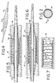
- Figures 4 through 7 generally show the use of the stent-graft 10 in the treatment of endovascular lesions.
- a stenosis or lesion 26 within blood vessel 28 is transluminally reached by a balloon catheter 20 having a stent-graft 10 in its first or unexpanded stable condition overlying the collapsed balloon 21 of the catheter 20.
- the balloon 21 is expanded in a known manner, at which time the stent-graft 10 is also expanded by the radial force exerted by the balloon 21.
- Figure 6 illustrates the balloon 21 and the stent-graft 10 in an intermediate dilation position with the lesion 26 initially dilated.
- Figure 7 shows full dilation of the lesion 26 following the withdrawal of the balloon catheter 20.
- the bistable stent-graft 10 has attained its second or expanded stable condition and remains in place within the blood vessel 28 because of the hoop stress exerted by the stent-member 14 once expanded, as illustrated in Figure 7.
- the stent member 14 must exert sufficient hoop stress to successfully resist inwardly directed radial forces presented by both the treated lesion 26 as well as the graft member 14.
- the stent-graft 10 of the present invention assumes an expanded diameter "D" ( Figure 7) which is typically two to six times that of the collapsed or unexpanded diameter "d" indicated in Figure 2. The more typical expansion of the stent-graft 10 is on the order of four times the collapsed diameter "d".
Description
Claims (11)
- A bistable luminal graft endoprosthesis comprising:a stent member (14) having a generally cylindrical external surface and a generally cylindrical internal surface said stent (14) member being expandable from a first diameter (d) at which it can be inserted into a human or animal body pathway and a second diameter (D) greater than said first diameter (d); anda polymeric material tubular graft member (12) that engages at least one of said generally cylindrical external and internal surfaces of said stent member (14); said graft member (12) has a collapsed stable configuration when said stent member (14) is at said first diameter (d) and assumes an expanded stable configuration when said stent member (14) is at said second expanded diameter (D);said polymeric material is capable of being substantially unstressed when at both said collapsed and expanded stable configurations; characterised in thatsaid graft member polymeric material has a Durometer hardness of 75 D or harder and has been prestretched to surpass the elastic yield point of the polymeric material, and said collapsed stable configuration of the graft member (12) is one at which the graft member (12), during manufacture, had been heat collapsed over at least one of said generally cylindrical surfaces of the stent member (14) to provide said collapsed stable configuration after the graft member polymeric material had been prestretched to surpass the elastic yield point; andsaid expanded stable configuration of the graft member (12) is one at which the graft member (12), during use, expands to said second diameter (D) after having been prestretched to surpass said elastic yield point.
- The bistable luminal graft endoprosthesis as defined in claim 1 wherein said tubular graft member (12) is made from a polymeric material selected from the group consisting essentially of polyester terephthalate, polytetrafluoroethylene, polyamide, polyurethane, polycarbonate polyurethane, poly(methylpentane), polypropylene, polyethylene, polyvinylchloride and combinations thereof.
- The bistable luminal graft endoprosthesis as defined in claim 1 wherein said polymeric material is a polycarbonate polyurethane.
- The bistable luminal graft endoprosthesis as defined in any of claims 1-3, wherein said tubular graft member (12) is made of woven, non-woven, knitted or film materials.
- The bistable luminal graft endoprosthesis as defined in any of claims 1-4, wherein said graft member (12) and said stent member (14) are capable of being expanded from said first diameter (d) to said second diameter (D) by the application of radially directed pressure from within said stent member.
- The bistable luminal graft endoprosthesis as defined in any of claims 1-5, wherein said graft member (12) and said stent member (14) are dimensioned for placement over a balloon (21) or a catheter (20) for insertion into a living body pathway (28).
- The bistable luminal graft endoprosthesis as defined in any of claims 1-6, wherein said tubular graft member (12) is secured to at least one of said generally cylindrical external and internal surfaces of said stent member (14), said polymeric material is orientable, and said graft member is constructed to surpass the elastic yield point of said orientable polymeric material so as to impart a non-elastomeric state to the graft member thereby avoiding substantially weakening said graft member when expanded to said second cross-sectional diameter (D) and implanted for extended time periods.
- The bistable luminal graft endoprosthesis of any of claims 1-7, wherein said stent member (14) includes a plurality of generally circumferential adjacent sections (22, 24) and wherein each said section includes at least one expandable segment which imparts radial expandability to said circumferential section.
- A method for the manufacture of a bistable luminal graft endoprosthesis, the method including:comprising the steps ofsupplying a stent member (14) having a generally cylindrical external surface and a generally cylindrical internal surface and capable of being expanded from a first cross-sectional diameter (d) to a second, expanded cross-sectional diameter (D) greater than said first cross-sectional diameter;preparing a tubular graft member (12) from a polymeric material having a Durometer hardness of 75D or harder, the tubular graft member having a collapsed stable configuration when the graft member has the first cross-sectional diameter (d), and said tubular graft member has an expanded stable configuration when the graft member has the second, expanded cross-sectional diameter (D), said preparing step including initially stretching the polymeric material of the tubular graft member (12) to surpass the elastic yield point of the polymeric material,applying said tubular graft member (12) to at least one of said generally cylindrical external and internal surfaces of said stent member (14),said applying step including heat collapsing said graft member (12) over said cylindrical surface of said stent member (14); andsaid preparing step includes selecting the polymeric material and tubular graft member (12) to be capable of being substantially unstressed when at both said first and second stable configurations.
- The method as defined in claim 9, wherein said preparing step includes constructing the graft member (12) of an orientable material to surpass the elastic yield point of said orientable material without substantially weakening said graft member when said graft member is expanded to said second cross-sectional diameter (D).
- The method as defined in claim 9 or 10, wherein said applying step includes bonding said graft member (12) to said stent member (14) by the use of thermobonding, adhesives, primers, coupling agents or combinations thereof.
Applications Claiming Priority (2)
| Application Number | Priority Date | Filing Date | Title |
|---|---|---|---|
| US26712194A | 1994-06-27 | 1994-06-27 | |
| US267121 | 1994-06-27 |
Publications (3)
| Publication Number | Publication Date |
|---|---|
| EP0689805A2 EP0689805A2 (en) | 1996-01-03 |
| EP0689805A3 EP0689805A3 (en) | 1996-08-21 |
| EP0689805B1 true EP0689805B1 (en) | 2003-05-28 |
Family
ID=23017402
Family Applications (1)
| Application Number | Title | Priority Date | Filing Date |
|---|---|---|---|
| EP95109038A Expired - Lifetime EP0689805B1 (en) | 1994-06-27 | 1995-06-12 | Bistable luminal graft endoprostheses |
Country Status (5)
| Country | Link |
|---|---|
| US (1) | US5755774A (en) |
| EP (1) | EP0689805B1 (en) |
| JP (1) | JP3361212B2 (en) |
| CA (1) | CA2152662C (en) |
| DE (1) | DE69530891T2 (en) |
Cited By (1)
| Publication number | Priority date | Publication date | Assignee | Title |
|---|---|---|---|---|
| US6790226B2 (en) | 1995-03-10 | 2004-09-14 | Bard Peripheral Vascular, Inc. | Endoluminal prosthesis with support wire |
Families Citing this family (100)
| Publication number | Priority date | Publication date | Assignee | Title |
|---|---|---|---|---|
| US6579314B1 (en) | 1995-03-10 | 2003-06-17 | C.R. Bard, Inc. | Covered stent with encapsulated ends |
| US6451047B2 (en) | 1995-03-10 | 2002-09-17 | Impra, Inc. | Encapsulated intraluminal stent-graft and methods of making same |
| US6193745B1 (en) * | 1995-10-03 | 2001-02-27 | Medtronic, Inc. | Modular intraluminal prosteheses construction and methods |
| US5824037A (en) * | 1995-10-03 | 1998-10-20 | Medtronic, Inc. | Modular intraluminal prostheses construction and methods |
| US6576009B2 (en) | 1995-12-01 | 2003-06-10 | Medtronic Ave, Inc. | Bifurcated intraluminal prostheses construction and methods |
| US5824040A (en) * | 1995-12-01 | 1998-10-20 | Medtronic, Inc. | Endoluminal prostheses and therapies for highly variable body lumens |
| FR2742994B1 (en) * | 1995-12-28 | 1998-04-03 | Sgro Jean-Claude | INTRACORPOREAL LIGHT SURGICAL TREATMENT ASSEMBLY |
| US5843158A (en) * | 1996-01-05 | 1998-12-01 | Medtronic, Inc. | Limited expansion endoluminal prostheses and methods for their use |
| DE69732794T2 (en) | 1996-01-05 | 2006-04-06 | Medtronic, Inc., Minneapolis | EXPANDABLE ENDOLUMINARY PROSTHESIS |
| CA2199890C (en) * | 1996-03-26 | 2002-02-05 | Leonard Pinchuk | Stents and stent-grafts having enhanced hoop strength and methods of making the same |
| US5843161A (en) * | 1996-06-26 | 1998-12-01 | Cordis Corporation | Endoprosthesis assembly for percutaneous deployment and method of deploying same |
| US5741326A (en) * | 1996-07-15 | 1998-04-21 | Cordis Corporation | Low profile thermally set wrapped cover for a percutaneously deployed stent |
| US6086610A (en) * | 1996-10-22 | 2000-07-11 | Nitinol Devices & Components | Composite self expanding stent device having a restraining element |
| US5925074A (en) * | 1996-12-03 | 1999-07-20 | Atrium Medical Corporation | Vascular endoprosthesis and method |
| US6010529A (en) * | 1996-12-03 | 2000-01-04 | Atrium Medical Corporation | Expandable shielded vessel support |
| US5961545A (en) * | 1997-01-17 | 1999-10-05 | Meadox Medicals, Inc. | EPTFE graft-stent composite device |
| US8353948B2 (en) | 1997-01-24 | 2013-01-15 | Celonova Stent, Inc. | Fracture-resistant helical stent incorporating bistable cells and methods of use |
| IL131063A (en) | 1997-01-24 | 2005-07-25 | Kentucky Oil N V | Bistable spring construction for a stent and other medical apparatus |
| US8663311B2 (en) | 1997-01-24 | 2014-03-04 | Celonova Stent, Inc. | Device comprising biodegradable bistable or multistable cells and methods of use |
| JP3645399B2 (en) * | 1997-06-09 | 2005-05-11 | 住友金属工業株式会社 | Endovascular stent |
| US6488701B1 (en) | 1998-03-31 | 2002-12-03 | Medtronic Ave, Inc. | Stent-graft assembly with thin-walled graft component and method of manufacture |
| AU3008599A (en) * | 1998-03-18 | 1999-10-11 | Meadox Medicals, Inc. | Improved ptfe vascular prosthesis and method of manufacture |
| US6264687B1 (en) | 1998-04-20 | 2001-07-24 | Cordis Corporation | Multi-laminate stent having superelastic articulated sections |
| US6099559A (en) * | 1998-05-28 | 2000-08-08 | Medtronic Ave, Inc. | Endoluminal support assembly with capped ends |
| ATE290833T1 (en) * | 1998-07-31 | 2005-04-15 | Evysio Medical Devices Ulc | EXPANDABLE STENT FOR SMALL VESSELS |
| US6156064A (en) * | 1998-08-14 | 2000-12-05 | Schneider (Usa) Inc | Stent-graft-membrane and method of making the same |
| US6143022A (en) * | 1998-08-24 | 2000-11-07 | Medtronic Ave, Inc. | Stent-graft assembly with dual configuration graft component and method of manufacture |
| US7887578B2 (en) | 1998-09-05 | 2011-02-15 | Abbott Laboratories Vascular Enterprises Limited | Stent having an expandable web structure |
| US6755856B2 (en) | 1998-09-05 | 2004-06-29 | Abbott Laboratories Vascular Enterprises Limited | Methods and apparatus for stenting comprising enhanced embolic protection, coupled with improved protection against restenosis and thrombus formation |
| US6682554B2 (en) * | 1998-09-05 | 2004-01-27 | Jomed Gmbh | Methods and apparatus for a stent having an expandable web structure |
| US7815763B2 (en) | 2001-09-28 | 2010-10-19 | Abbott Laboratories Vascular Enterprises Limited | Porous membranes for medical implants and methods of manufacture |
| US20020065546A1 (en) * | 1998-12-31 | 2002-05-30 | Machan Lindsay S. | Stent grafts with bioactive coatings |
| US20050171594A1 (en) * | 1998-12-31 | 2005-08-04 | Angiotech International Ag | Stent grafts with bioactive coatings |
| AU768150B2 (en) | 1999-01-22 | 2003-12-04 | W.L. Gore & Associates, Inc. | A biliary stent-graft |
| US6558414B2 (en) | 1999-02-02 | 2003-05-06 | Impra, Inc. | Partial encapsulation of stents using strips and bands |
| US6398803B1 (en) | 1999-02-02 | 2002-06-04 | Impra, Inc., A Subsidiary Of C.R. Bard, Inc. | Partial encapsulation of stents |
| GB2347861B (en) * | 1999-03-13 | 2003-11-26 | Biointeractions Ltd | Biocompatible endoprostheses |
| US6425855B2 (en) | 1999-04-06 | 2002-07-30 | Cordis Corporation | Method for making a multi-laminate stent having superelastic articulated sections |
| DE29907827U1 (en) * | 1999-05-03 | 1999-07-22 | Jomed Implantate Gmbh | Stent catheter assembly |
| CA2370804C (en) * | 1999-05-20 | 2010-01-05 | Boston Scientific Limited | Stent-graft with increased flexibility |
| US6673103B1 (en) | 1999-05-20 | 2004-01-06 | Scimed Life Systems, Inc. | Mesh and stent for increased flexibility |
| US6364904B1 (en) * | 1999-07-02 | 2002-04-02 | Scimed Life Systems, Inc. | Helically formed stent/graft assembly |
| US6334868B1 (en) | 1999-10-08 | 2002-01-01 | Advanced Cardiovascular Systems, Inc. | Stent cover |
| DE10004832A1 (en) * | 2000-01-31 | 2001-08-16 | Ethicon Gmbh | Flat implant with X-ray visible elements |
| US7220276B1 (en) * | 2000-03-06 | 2007-05-22 | Surmodics, Inc. | Endovascular graft coatings |
| US6799637B2 (en) | 2000-10-20 | 2004-10-05 | Schlumberger Technology Corporation | Expandable tubing and method |
| WO2002015824A2 (en) * | 2000-08-25 | 2002-02-28 | Kensey Nash Corporation | Covered stents, systems for deploying covered stents |
| AU2001286940A1 (en) | 2000-09-22 | 2002-04-02 | Kensey Nash Corporation | Drug delivering prostheses and methods of use |
| US20040030377A1 (en) * | 2001-10-19 | 2004-02-12 | Alexander Dubson | Medicated polymer-coated stent assembly |
| US7244272B2 (en) | 2000-12-19 | 2007-07-17 | Nicast Ltd. | Vascular prosthesis and method for production thereof |
| US20070031607A1 (en) * | 2000-12-19 | 2007-02-08 | Alexander Dubson | Method and apparatus for coating medical implants |
| US20020084178A1 (en) * | 2000-12-19 | 2002-07-04 | Nicast Corporation Ltd. | Method and apparatus for manufacturing polymer fiber shells via electrospinning |
| US6641607B1 (en) | 2000-12-29 | 2003-11-04 | Advanced Cardiovascular Systems, Inc. | Double tube stent |
| NO335594B1 (en) | 2001-01-16 | 2015-01-12 | Halliburton Energy Serv Inc | Expandable devices and methods thereof |
| JP2004530054A (en) * | 2001-03-20 | 2004-09-30 | ナイキャスト リミテッド | Method and apparatus for improving the mechanical properties of nonwoven materials |
| EP1372531A2 (en) * | 2001-03-30 | 2004-01-02 | Terumo Kabushiki Kaisha | Stent cover and stent |
| US6719804B2 (en) | 2001-04-02 | 2004-04-13 | Scimed Life Systems, Inc. | Medical stent and related methods |
| US6620202B2 (en) | 2001-10-16 | 2003-09-16 | Scimed Life Systems, Inc. | Medical stent with variable coil and related methods |
| US7192441B2 (en) | 2001-10-16 | 2007-03-20 | Scimed Life Systems, Inc. | Aortic artery aneurysm endovascular prosthesis |
| US7033389B2 (en) | 2001-10-16 | 2006-04-25 | Scimed Life Systems, Inc. | Tubular prosthesis for external agent delivery |
| ATE425720T1 (en) * | 2002-01-28 | 2009-04-15 | Orbusneich Medical Inc | EXPANDED OSTIUM ENDPROSTHESIS AND DELIVERY SYSTEM |
| US6949121B1 (en) | 2002-02-07 | 2005-09-27 | Sentient Engineering & Technology, Llc | Apparatus and methods for conduits and materials |
| AU2003300022A1 (en) * | 2002-12-30 | 2004-07-29 | Angiotech International Ag | Silk-containing stent graft |
| US20040126405A1 (en) * | 2002-12-30 | 2004-07-01 | Scimed Life Systems, Inc. | Engineered scaffolds for promoting growth of cells |
| JP2007521843A (en) | 2003-05-15 | 2007-08-09 | バイオメリクス コーポレーション | Reticulated elastomeric matrix, its manufacture and use in implantable devices |
| WO2005046747A2 (en) * | 2003-11-10 | 2005-05-26 | Angiotech International Ag | Intravascular devices and fibrosis-inducing agents |
| US8435285B2 (en) * | 2003-11-25 | 2013-05-07 | Boston Scientific Scimed, Inc. | Composite stent with inner and outer stent elements and method of using the same |
| US20050113904A1 (en) * | 2003-11-25 | 2005-05-26 | Shank Peter J. | Composite stent with inner and outer stent elements and method of using the same |
| US7763077B2 (en) | 2003-12-24 | 2010-07-27 | Biomerix Corporation | Repair of spinal annular defects and annulo-nucleoplasty regeneration |
| WO2005065578A2 (en) * | 2004-01-06 | 2005-07-21 | Nicast Ltd. | Vascular prosthesis with anastomotic member |
| US20050216043A1 (en) * | 2004-03-26 | 2005-09-29 | Blatter Duane D | Stented end graft vessel device for anastomosis and related methods for percutaneous placement |
| US20060079954A1 (en) * | 2004-10-08 | 2006-04-13 | Robert Burgermeister | Geometry and material for high strength, high flexibility, controlled recoil stent |
| US8771294B2 (en) * | 2004-11-26 | 2014-07-08 | Biomerix Corporation | Aneurysm treatment devices and methods |
| US20100331947A1 (en) * | 2005-02-17 | 2010-12-30 | Alon Shalev | Inflatable Medical Device |
| JP5203192B2 (en) * | 2005-07-27 | 2013-06-05 | クック メディカル テクノロジーズ エルエルシー | Stent / graft device and method for placement in open surgery |
| US8348991B2 (en) * | 2006-03-29 | 2013-01-08 | Boston Scientific Scimed, Inc. | Stent with overlap and high expansion |
| US8043358B2 (en) * | 2006-03-29 | 2011-10-25 | Boston Scientific Scimed, Inc. | Stent with overlap and high extension |
| JP2010504820A (en) * | 2006-09-28 | 2010-02-18 | クック・インコーポレイテッド | Apparatus and method for repairing a thoracic aortic aneurysm |
| US9622888B2 (en) * | 2006-11-16 | 2017-04-18 | W. L. Gore & Associates, Inc. | Stent having flexibly connected adjacent stent elements |
| US8016874B2 (en) | 2007-05-23 | 2011-09-13 | Abbott Laboratories Vascular Enterprises Limited | Flexible stent with elevated scaffolding properties |
| US8128679B2 (en) * | 2007-05-23 | 2012-03-06 | Abbott Laboratories Vascular Enterprises Limited | Flexible stent with torque-absorbing connectors |
| US8906081B2 (en) | 2007-09-13 | 2014-12-09 | W. L. Gore & Associates, Inc. | Stented vascular graft |
| US7850726B2 (en) * | 2007-12-20 | 2010-12-14 | Abbott Laboratories Vascular Enterprises Limited | Endoprosthesis having struts linked by foot extensions |
| US8337544B2 (en) * | 2007-12-20 | 2012-12-25 | Abbott Laboratories Vascular Enterprises Limited | Endoprosthesis having flexible connectors |
| US8920488B2 (en) | 2007-12-20 | 2014-12-30 | Abbott Laboratories Vascular Enterprises Limited | Endoprosthesis having a stable architecture |
| US8926688B2 (en) | 2008-01-11 | 2015-01-06 | W. L. Gore & Assoc. Inc. | Stent having adjacent elements connected by flexible webs |
| US8196279B2 (en) | 2008-02-27 | 2012-06-12 | C. R. Bard, Inc. | Stent-graft covering process |
| EP3735937A1 (en) | 2009-11-30 | 2020-11-11 | Endospan Ltd. | Multi-component stent-graft system for implantation in a blood vessel with multiple branches |
| US9526638B2 (en) | 2011-02-03 | 2016-12-27 | Endospan Ltd. | Implantable medical devices constructed of shape memory material |
| US9486341B2 (en) | 2011-03-02 | 2016-11-08 | Endospan Ltd. | Reduced-strain extra-vascular ring for treating aortic aneurysm |
| EP2729095B1 (en) | 2011-07-07 | 2016-10-26 | Endospan Ltd. | Stent fixation with reduced plastic deformation |
| US9839510B2 (en) * | 2011-08-28 | 2017-12-12 | Endospan Ltd. | Stent-grafts with post-deployment variable radial displacement |
| US10154918B2 (en) | 2012-12-28 | 2018-12-18 | Cook Medical Technologies Llc | Endoluminal prosthesis with fiber matrix |
| WO2014108895A2 (en) | 2013-01-08 | 2014-07-17 | Endospan Ltd. | Minimization of stent-graft migration during implantation |
| EP2967830B1 (en) | 2013-03-11 | 2017-11-01 | Endospan Ltd. | Multi-component stent-graft system for aortic dissections |
| WO2015075708A1 (en) | 2013-11-19 | 2015-05-28 | Endospan Ltd. | Stent system with radial-expansion locking |
| US10299948B2 (en) | 2014-11-26 | 2019-05-28 | W. L. Gore & Associates, Inc. | Balloon expandable endoprosthesis |
| WO2016098113A1 (en) | 2014-12-18 | 2016-06-23 | Endospan Ltd. | Endovascular stent-graft with fatigue-resistant lateral tube |
| CN106137459B (en) * | 2015-08-20 | 2018-02-23 | 上海市浦东医院 | The method of the interim film covering device of intravascular stent and the interim overlay film of intravascular stent |
| US10568752B2 (en) | 2016-05-25 | 2020-02-25 | W. L. Gore & Associates, Inc. | Controlled endoprosthesis balloon expansion |
Family Cites Families (35)
| Publication number | Priority date | Publication date | Assignee | Title |
|---|---|---|---|---|
| GB1205743A (en) * | 1966-07-15 | 1970-09-16 | Nat Res Dev | Surgical dilator |
| US4374669A (en) * | 1975-05-09 | 1983-02-22 | Mac Gregor David C | Cardiovascular prosthetic devices and implants with porous systems |
| US4173689A (en) * | 1976-02-03 | 1979-11-06 | University Of Utah | Synthetic polymer prosthesis material |
| DE2960875D1 (en) * | 1978-04-19 | 1981-12-10 | Ici Plc | A method of preparing a tubular product by electrostatic spinning |
| DE2965672D1 (en) * | 1978-10-10 | 1983-07-21 | Ici Plc | Production of electrostatically spun products |
| GB2115776B (en) * | 1982-03-02 | 1986-03-12 | Ontario Research Foundation | Implantable material |
| US4475972A (en) * | 1981-10-01 | 1984-10-09 | Ontario Research Foundation | Implantable material |
| SE445884B (en) * | 1982-04-30 | 1986-07-28 | Medinvent Sa | DEVICE FOR IMPLANTATION OF A RODFORM PROTECTION |
| US4512338A (en) * | 1983-01-25 | 1985-04-23 | Balko Alexander B | Process for restoring patency to body vessels |
| US4503569A (en) * | 1983-03-03 | 1985-03-12 | Dotter Charles T | Transluminally placed expandable graft prosthesis |
| US4580568A (en) * | 1984-10-01 | 1986-04-08 | Cook, Incorporated | Percutaneous endovascular stent and method for insertion thereof |
| US4651721A (en) * | 1985-04-10 | 1987-03-24 | American Medical Systems, Inc. | Penile prosthesis system |
| US4712553A (en) * | 1985-05-30 | 1987-12-15 | Cordis Corporation | Sutures having a porous surface |
| US4733665C2 (en) * | 1985-11-07 | 2002-01-29 | Expandable Grafts Partnership | Expandable intraluminal graft and method and apparatus for implanting an expandable intraluminal graft |
| US4738740A (en) * | 1985-11-21 | 1988-04-19 | Corvita Corporation | Method of forming implantable vascular grafts |
| US4800882A (en) * | 1987-03-13 | 1989-01-31 | Cook Incorporated | Endovascular stent and delivery system |
| US4932958A (en) * | 1988-05-10 | 1990-06-12 | American Medical Systems, Inc. | Prostate balloon dilator |
| US5092877A (en) * | 1988-09-01 | 1992-03-03 | Corvita Corporation | Radially expandable endoprosthesis |
| US5019090A (en) * | 1988-09-01 | 1991-05-28 | Corvita Corporation | Radially expandable endoprosthesis and the like |
| US4873308A (en) * | 1988-09-30 | 1989-10-10 | Medtronic, Inc. | Biostable, segmented aliphatic polyurethanes and process therefor |
| CA1322628C (en) * | 1988-10-04 | 1993-10-05 | Richard A. Schatz | Expandable intraluminal graft |
| US4950227A (en) * | 1988-11-07 | 1990-08-21 | Boston Scientific Corporation | Stent delivery system |
| US4994071A (en) * | 1989-05-22 | 1991-02-19 | Cordis Corporation | Bifurcating stent apparatus and method |
| DE3918736C2 (en) * | 1989-06-08 | 1998-05-14 | Christian Dr Vallbracht | Plastic-coated metal mesh stents |
| US5171262A (en) * | 1989-06-15 | 1992-12-15 | Cordis Corporation | Non-woven endoprosthesis |
| US4995872A (en) * | 1989-10-04 | 1991-02-26 | Ferrara Janice J | Expandable catheter and bridge device |
| EP0461791B1 (en) * | 1990-06-11 | 1997-01-02 | Hector D. Barone | Aortic graft and apparatus for repairing an abdominal aortic aneurysm |
| CA2038605C (en) * | 1990-06-15 | 2000-06-27 | Leonard Pinchuk | Crack-resistant polycarbonate urethane polymer prostheses and the like |
| US5122154A (en) * | 1990-08-15 | 1992-06-16 | Rhodes Valentine J | Endovascular bypass graft |
| US5139480A (en) * | 1990-08-22 | 1992-08-18 | Biotech Laboratories, Inc. | Necking stents |
| JPH0717314Y2 (en) * | 1990-10-18 | 1995-04-26 | ソン ホーヨン | Self-expanding intravascular stent |
| US5156620A (en) * | 1991-02-04 | 1992-10-20 | Pigott John P | Intraluminal graft/stent and balloon catheter for insertion thereof |
| US5405377A (en) * | 1992-02-21 | 1995-04-11 | Endotech Ltd. | Intraluminal stent |
| US5282823A (en) * | 1992-03-19 | 1994-02-01 | Medtronic, Inc. | Intravascular radially expandable stent |
| ES2170093T3 (en) * | 1993-01-14 | 2002-08-01 | Meadox Medicals Inc | RADIAL EXPANDABLE TUBULAR PROTESIS. |
-
1995
- 1995-06-12 DE DE69530891T patent/DE69530891T2/en not_active Expired - Lifetime
- 1995-06-12 EP EP95109038A patent/EP0689805B1/en not_active Expired - Lifetime
- 1995-06-20 JP JP15324395A patent/JP3361212B2/en not_active Expired - Fee Related
- 1995-06-26 CA CA002152662A patent/CA2152662C/en not_active Expired - Fee Related
-
1996
- 1996-08-22 US US08/701,557 patent/US5755774A/en not_active Expired - Lifetime
Cited By (1)
| Publication number | Priority date | Publication date | Assignee | Title |
|---|---|---|---|---|
| US6790226B2 (en) | 1995-03-10 | 2004-09-14 | Bard Peripheral Vascular, Inc. | Endoluminal prosthesis with support wire |
Also Published As
| Publication number | Publication date |
|---|---|
| CA2152662A1 (en) | 1995-12-28 |
| JPH0838519A (en) | 1996-02-13 |
| EP0689805A3 (en) | 1996-08-21 |
| DE69530891D1 (en) | 2003-07-03 |
| US5755774A (en) | 1998-05-26 |
| JP3361212B2 (en) | 2003-01-07 |
| CA2152662C (en) | 2003-10-21 |
| DE69530891T2 (en) | 2004-05-13 |
| EP0689805A2 (en) | 1996-01-03 |
Similar Documents
| Publication | Publication Date | Title |
|---|---|---|
| EP0689805B1 (en) | Bistable luminal graft endoprostheses | |
| AU781586B2 (en) | Stent-graft with helically arranged securement member | |
| US5632772A (en) | Expandable supportive branched endoluminal grafts | |
| US6652570B2 (en) | Composite vascular graft | |
| JP3938598B2 (en) | Coated stent | |
| US5855598A (en) | Expandable supportive branched endoluminal grafts | |
| US6929709B2 (en) | Helically formed stent/graft assembly | |
| US20010018609A1 (en) | Seamless braided or spun stent cover | |
| WO1997017913A9 (en) | Expandable supportive branched endoluminal grafts | |
| US20080221668A1 (en) | Expandable supportive branched endoluminal grafts | |
| CA2429619C (en) | Composite tubular prostheses | |
| AU736766B2 (en) | Endoluminal component with indent |
Legal Events
| Date | Code | Title | Description |
|---|---|---|---|
| PUAI | Public reference made under article 153(3) epc to a published international application that has entered the european phase |
Free format text: ORIGINAL CODE: 0009012 |
|
| AK | Designated contracting states |
Kind code of ref document: A2 Designated state(s): DE FR GB IT NL |
|
| PUAL | Search report despatched |
Free format text: ORIGINAL CODE: 0009013 |
|
| AK | Designated contracting states |
Kind code of ref document: A3 Designated state(s): DE FR GB IT NL |
|
| 17P | Request for examination filed |
Effective date: 19961111 |
|
| 17Q | First examination report despatched |
Effective date: 19980810 |
|
| GRAH | Despatch of communication of intention to grant a patent |
Free format text: ORIGINAL CODE: EPIDOS IGRA |
|
| GRAH | Despatch of communication of intention to grant a patent |
Free format text: ORIGINAL CODE: EPIDOS IGRA |
|
| GRAA | (expected) grant |
Free format text: ORIGINAL CODE: 0009210 |
|
| AK | Designated contracting states |
Designated state(s): DE FR GB IT NL |
|
| REG | Reference to a national code |
Ref country code: GB Ref legal event code: FG4D |
|
| REF | Corresponds to: |
Ref document number: 69530891 Country of ref document: DE Date of ref document: 20030703 Kind code of ref document: P |
|
| ET | Fr: translation filed | ||
| PLBE | No opposition filed within time limit |
Free format text: ORIGINAL CODE: 0009261 |
|
| STAA | Information on the status of an ep patent application or granted ep patent |
Free format text: STATUS: NO OPPOSITION FILED WITHIN TIME LIMIT |
|
| 26N | No opposition filed |
Effective date: 20040302 |
|
| PGFP | Annual fee paid to national office [announced via postgrant information from national office to epo] |
Ref country code: FR Payment date: 20100617 Year of fee payment: 16 |
|
| PGFP | Annual fee paid to national office [announced via postgrant information from national office to epo] |
Ref country code: IT Payment date: 20100621 Year of fee payment: 16 |
|
| PGFP | Annual fee paid to national office [announced via postgrant information from national office to epo] |
Ref country code: NL Payment date: 20100607 Year of fee payment: 16 |
|
| PGFP | Annual fee paid to national office [announced via postgrant information from national office to epo] |
Ref country code: GB Payment date: 20100401 Year of fee payment: 16 Ref country code: DE Payment date: 20100630 Year of fee payment: 16 |
|
| REG | Reference to a national code |
Ref country code: NL Ref legal event code: V1 Effective date: 20120101 |
|
| GBPC | Gb: european patent ceased through non-payment of renewal fee |
Effective date: 20110612 |
|
| PG25 | Lapsed in a contracting state [announced via postgrant information from national office to epo] |
Ref country code: IT Free format text: LAPSE BECAUSE OF NON-PAYMENT OF DUE FEES Effective date: 20110612 |
|
| REG | Reference to a national code |
Ref country code: FR Ref legal event code: ST Effective date: 20120229 |
|
| REG | Reference to a national code |
Ref country code: DE Ref legal event code: R119 Ref document number: 69530891 Country of ref document: DE Effective date: 20120103 |
|
| PG25 | Lapsed in a contracting state [announced via postgrant information from national office to epo] |
Ref country code: DE Free format text: LAPSE BECAUSE OF NON-PAYMENT OF DUE FEES Effective date: 20120103 Ref country code: FR Free format text: LAPSE BECAUSE OF NON-PAYMENT OF DUE FEES Effective date: 20110630 |
|
| PG25 | Lapsed in a contracting state [announced via postgrant information from national office to epo] |
Ref country code: NL Free format text: LAPSE BECAUSE OF NON-PAYMENT OF DUE FEES Effective date: 20120101 |
|
| PG25 | Lapsed in a contracting state [announced via postgrant information from national office to epo] |
Ref country code: GB Free format text: LAPSE BECAUSE OF NON-PAYMENT OF DUE FEES Effective date: 20110612 |