EP0691284A2 - Dispenser for pasty substances - Google Patents
Dispenser for pasty substances Download PDFInfo
- Publication number
- EP0691284A2 EP0691284A2 EP95110328A EP95110328A EP0691284A2 EP 0691284 A2 EP0691284 A2 EP 0691284A2 EP 95110328 A EP95110328 A EP 95110328A EP 95110328 A EP95110328 A EP 95110328A EP 0691284 A2 EP0691284 A2 EP 0691284A2
- Authority
- EP
- European Patent Office
- Prior art keywords
- dispenser according
- housing
- valve
- piston
- dispenser
- Prior art date
- Legal status (The legal status is an assumption and is not a legal conclusion. Google has not performed a legal analysis and makes no representation as to the accuracy of the status listed.)
- Granted
Links
Images


Classifications
-
- B—PERFORMING OPERATIONS; TRANSPORTING
- B65—CONVEYING; PACKING; STORING; HANDLING THIN OR FILAMENTARY MATERIAL
- B65D—CONTAINERS FOR STORAGE OR TRANSPORT OF ARTICLES OR MATERIALS, e.g. BAGS, BARRELS, BOTTLES, BOXES, CANS, CARTONS, CRATES, DRUMS, JARS, TANKS, HOPPERS, FORWARDING CONTAINERS; ACCESSORIES, CLOSURES, OR FITTINGS THEREFOR; PACKAGING ELEMENTS; PACKAGES
- B65D83/00—Containers or packages with special means for dispensing contents
- B65D83/0005—Containers or packages provided with a piston or with a movable bottom or partition having approximately the same section as the container
- B65D83/0033—Containers or packages provided with a piston or with a movable bottom or partition having approximately the same section as the container the piston being a follower-piston and the dispensing means comprising a hand-operated pressure-device at the opposite part of the container
Definitions
- the invention relates to a dispenser for pasty masses with a housing in which a piston which can only be displaced in the emptying direction and can be supported in the opposite direction by a ratchet against the inner wall of the housing is arranged and which is used to displace a portion of the mass to be dispensed by one stroke each Compressible push button has or can be depressed head part, the push button being arranged laterally next to the head part and this having a central valve which can be opened or closed by actuating the push button.
- a dispenser of this type is known from EP 0 282 791 B1.
- a portion of the mass to be dispensed is displaced from the contents of the housing by a stroke of the pushbutton with simultaneous opening of a valve arranged centrally in the head part and emerges from a concave wall of the head part designed as an application surface.
- a vacuum is created in the level column below the head part that straightens up again, which pulls the piston in the direction of emptying.
- the portion of pasty mass displaced by actuating the deformable head part is added for the next dispensing operation.
- the known dispenser is consequently filled with the dispenser head pointing downward.
- the initial area of the housing inner wall is designed with longitudinal grooves so that air trapped between the piston and the filling material can escape.
- a dispenser for pasty masses is also known, with a piston which is displaceably arranged in the dispenser housing, migrates in the discharge direction and is blocked in the opposite direction, and with a pushbutton actuation on a bellows-type compressible head piece, with this a pull rod penetrating the piston is coupled.
- the pull rod is coupled to the piston with the interposition of an axial free passage in the head piece.
- the headpiece has a channel-shaped dispenser mouthpiece opening, the mouth of which can be closed with a stopper for storage. This stopper is removed when the dispenser is opened, after which the mouthpiece opening remains unlocked for further withdrawals.
- the invention has for its object to further develop and improve a dispenser for pasty masses of the type mentioned in such a way that the disadvantages and difficulties mentioned are overcome and in particular none subsequent leakage of mass can take place after actuation, that the displaced portion of mass is safely brought in without damage, even from small air pockets, and that the dispenser can be manufactured and assembled inexpensively using simple structural means.
- valve and the piston are coupled by a pull rod axially penetrating the housing and cooperate with each other with each stroke of the push button.
- the valve is opened when the pushbutton is actuated and on the other hand a predetermined portion of mass is brought out of the valve opening through the opened valve and made available.
- the valve closes, and the head part, which straightens up again to its relaxed shape, pulls the piston so far over the pull rod that it replenishes the dispensed mass regardless of a more or less large suction.
- the clearance of the tie rod connection in the head part produces a shorter stroke of the piston compared to a relatively larger actuation stroke when the shape of the head part changes.
- the Tension rod in the head part has a holder in the form of a perforated radial disc, with which it is gripped in a guide cylinder of the head part with little axial clearance from the lower edge of the guide cylinder and is held so that it can be clipped in, and with its end part with the interposition of an internal locking mechanism present on the piston crown the piston can be coupled.
- the pull rod can thus be clipped into the guide cylinder and inserted through the piston without any assembly effort.
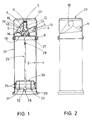
- the dispenser for pasty masses shown in FIG. 1 has a housing (1) in which a piston (30) is arranged, which can only be moved in the emptying direction and supported in the opposite direction by a locking mechanism (31) against the inner wall (2) of the housing (1) is.
- the latter has elastic sealing lips (34) that seal in both directions on its outer circumference in the usual way.
- the dispenser has a head part (3) which can be pressed together or depressed by a stroke of a pushbutton (4), the pushbutton (4) being arranged laterally next to the head part (3) and pressing the pushbutton (4) openable or closable, in the middle arranged shut-off valve (5).
- the head part (3) can be covered by a cap (23) which can be assigned to the dispenser.
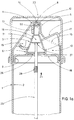
- the valve (5) and the piston (30) are coupled by means of a pull rod (25) which axially penetrates the housing (1) and cooperates with each other when the pushbutton (4) is lifted.
- the interaction is achieved in that the pull rod (25) is held by a holder (26) in the form of a perforated radial disk in a guide cylinder (6) of the valve body (7) with little axial clearance and with its, the piston (30) facing End part (28) with the interposition of a locking mechanism (32) present on the piston crown (33) is non-positively coupled to the piston (30).
- the housing cover (18) is pressed down and displaces a predetermined portion of the filling compound in the direction of the closing valve (5).
- the housing cover (18) is designed to be very elastic in the manner of a membrane with a relatively thin wall thickness, so that it yields under the pressure of the pushbutton (4) and practically performs a "pump stroke".
- the valve mechanism is activated and the valve (5) opens by the head part (3) connected to the housing cover (18) with the funnel-shaped discharge (19) and the discharge tube (12) arranged thereon within the cap (11) of the Applicator (10), as can be seen from the enlarged representation of Figures 1a and 3, slides down in the direction of arrow (24) and thereby releases the valve plug (14) from its closed position in the valve opening (8) and releases it.
- the housing (1) forms a neck (9) with a reduced diameter on the upper area, which receives the applicator (10), said neck having a cylindrical cap (11) which is provided with a valve opening (8) and can be opened downwards, in which a tube (12), which first extends upward from the head part (3) and forms part of the valve (5), slides axially displaceably and carries a valve plug (14) at its tip on star-shaped arms (13).
- the tube (12) is designed with an annular, elastic sealing bead (50), as is better can be seen from Figure 3. This seal could alternatively be formed with a highly elastic sealing lip or with an O-ring.
- the applicator (10) has a lateral opening (15) within which the pushbutton (4) is arranged, said pushbutton (4) being movably articulated on the gusset-like ribs (16) formed inside the applicator (10). Furthermore, the pushbutton (4) has on its outside a stop bead (17) designed as a stroke limiting element. This sits on the outer edge of the recess (15) and in this way limits the stroke. This prevents the housing cover (18) from being deformed too much and thus being overstretched or overstressed.
- the pull rod (25) protrudes into the discharge (19) and is thus extended upwards over the holder (26). At the extended end it carries a centering plate (27). This has a valve function, by pressing the Housing cover (18) first reduced an annular gap with respect to the discharge (19) and then blocked, whereby the amount of filling material escaping during the working stroke of the key (4) is limited.
- the centering plate (27) and the pull rod (25) are each designed as an independent molded part and the two parts can be joined together by plugging on. The assembly of both parts - as is common in the mass production of small parts - can then be carried out inexpensively using automatic assembly machines.
- the dispenser has an advantageous embodiment in that the pull rod (25) is provided with a corrugation (29) in an area just below the neck (9) of the housing (1). If the piston (30) slides over this corrugation (29) shortly before the final emptying, a clicking noise is caused, which indicates that the dispenser is about to be emptied.
- the very advantageous embodiment shown in Figure 1 also provides that the housing (1) with stand base (20), storage cylinder (21), neck (9), cover (18) and head part (3) consists in one piece of medium-hard thermoplastic material. This simplifies assembly, reduces the number of parts belonging to the dispenser assembly and enables very economical production in large quantities.
- the more highly stressed elements of the dispenser such as the piston (30), applicator (10), pushbutton (4), assignable cap (23) and the pull rod (25), on the other hand, can consist of a comparatively hard thermoplastic material.
- Figure 1a shows the top of the dispenser in an enlarged view, from which the assignments of the aforementioned elements can be seen better. All elements are provided with reference numerals corresponding to FIG. 1.
- FIG. 2 shows the dispenser in a side view, from which the shape of the applicator (10), which can be recognized, for example, by a transparent cap, can be seen.
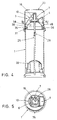
- valve plug (14) which tapers conically at both ends, is suitable for achieving a hermetic seal of the valve opening (8) with a low axial sealing force.
- the valve plug (14) is moved downward and releases the valve opening (8).
- the valve arrangement is uncomplicated, expedient and suitable for inexpensive manufacture.
- FIG 4 shows a slightly different embodiment of the dispenser.
- the housing (1) is open at the top and forms an annular groove (35) with an inward diameter and open at the top and a collar (36) with a clip groove (37) on the outside.
- the head part (3) has a dome-shaped attachment (38) which can be inserted into the annular groove (35) and has a flange (39) which overlaps the annular groove (35) and which is separated from an inner flange (40) of the collar (36).
- clip-on applicator (10) is held.
- This version also shows a corrugation (29) on the piston rod (25).
- the head part of the piston (30) is Dome-shaped in accordance with the dome-shaped design of the attachment (38) in a compatible design, whereby an almost complete emptying of the filling content of the dispenser is achieved.
- the remaining elements of the head part (3) with the valve body (7) and further elements correspond to the design and arrangement according to FIG. 1.
- Figure 5 shows a section of the plane (VV) in Fig. 4, the tie rod holder (26) in the form of a perforated disc within the guide cylinder (6), the arrangement of the push button (4) and the applicator (10) and also the housing with the open annular groove (35) only partially indicated for reasons of clarity.
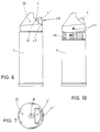
- Figure 6 shows a side view of a dispenser with the cap removed and a double push button (4 ', 4'') designed as a child safety device.
- the element (4 '') in the part (4 ') is axially telescopically displaced against the pressure of a spring in the locked state, as shown in FIG. 6, and lies on the edge (47) of the opening (15) of the applicator (10). In this state, it is not possible to depress the actuation button (4 ', 4'') for the working stroke. For this purpose, the part (4 '') must be pushed telescopically into the part (4 ') against the pressure of a return spring in the direction of the arrow (48).
- Figure 10 shows another version of the child lock.
- the dispenser has a locking ring (46) on the housing (1). This is designed in cooperation with the push button (4) so that it only releases the push button (4) in a certain position and recognizable by markings (44) if they match.
Abstract
Description
Die Erfindung betrifft einen Spender für pastöse Massen mit einem Gehäuse, in welchem ein nur in Entleerungsrichtung verlagerbarer und in Gegenrichtung von einem Gesperre gegen die Innenwand des Gehäuses abstützbarer Kolben angeordnet ist und welches zur Verdrängung einer zu spendenden Portion der Masse ein durch jeweils einen Hub einer Drucktaste zusammen- bzw. niederdrückbares Kopfteil aufweist, wobei die Drucktaste seitlich neben dem Kopfteil angeordnet ist und dieses ein mit der Betätigung der Drucktaste öffen- oder schließbares, mittig angeordnetes Abschlußventil aufweist.The invention relates to a dispenser for pasty masses with a housing in which a piston which can only be displaced in the emptying direction and can be supported in the opposite direction by a ratchet against the inner wall of the housing is arranged and which is used to displace a portion of the mass to be dispensed by one stroke each Compressible push button has or can be depressed head part, the push button being arranged laterally next to the head part and this having a central valve which can be opened or closed by actuating the push button.
Ein Spender dieser Art ist durch die EP 0 282 791 B1 bekannt. Bei diesem wird durch jeweils einen Hub der Drucktaste bei gleichzeitiger Öffnung eines mittig im Kopfteil angeordneten Ventils eine zu spendende Portion der Masse aus dem Gehäuseinhalt verdrängt und tritt an einer als Auftragsfläche ausgebildeten konkaven Wand des Kopfteils aus. Sobald die Drucktaste entlastet und das Ventil im Kopfteil geschlossen ist, entsteht in der Füllstandssäule unterhalb des sich wieder aufrichtenden Kopfteils ein Unterdruck, der den Kolben in Entleerungsrichtung nachzieht. Dabei wird der durch Betätigung des verformbaren Kopfteils verdrängte Anteil an pastöser Masse für die nächste Ausgabebetätigung nachgebracht. Dies bedingt, daß in der Füllsäule zwischen Oberseite Kolben und Unterseite Kopfteil keine Lufteinschlüsse vorhanden sein dürfen. Diese würden die Pumpwirkung ganz oder teilweise aufheben. Der bekannte Spender wird infolgedessen bei nach unten weisendem Spenderkopf gefüllt. Damit zwischen Kolben und füllgut eingeschlossene Luft entweichen kann, ist der Anfangsbereich der Gehäuseinnenwandung mit Längsriefen ausgebildet.A dispenser of this type is known from EP 0 282 791 B1. In this case, a portion of the mass to be dispensed is displaced from the contents of the housing by a stroke of the pushbutton with simultaneous opening of a valve arranged centrally in the head part and emerges from a concave wall of the head part designed as an application surface. As soon as the pushbutton is relieved and the valve in the head part is closed, a vacuum is created in the level column below the head part that straightens up again, which pulls the piston in the direction of emptying. The portion of pasty mass displaced by actuating the deformable head part is added for the next dispensing operation. This means that there must be no air pockets in the filling column between the top of the piston and the bottom of the head section. These would partially or completely cancel the pumping effect. The known dispenser is consequently filled with the dispenser head pointing downward. The initial area of the housing inner wall is designed with longitudinal grooves so that air trapped between the piston and the filling material can escape.
Aus der DE 30 45 048 C2 ist weiterhin ein Spender für pastöse Massen bekannt, mit im Spendergehäuse verschieblich angeordnetem, in Austragsrichtung wanderndem und in Gegenrichtung blockiertem Kolben sowie mit einer Drucktasten-Betätigung an einem balgartig zusammendrückbaren Kopfstück, wobei mit diesem eine den Kolben durchsetzende Zugstange gekuppelt ist. Die Zugstange ist unter Zwischenschaltung eines axialen Freiganges im Kopfstück mit dem Kolben gekuppelt. Das Kopfstück weist eine kanalartig ausgebildete Spender-Mundstücköffnung auf, deren Mündung für die Lagerhaltung mit einem Stopfen verschließbar ist. Dieser Stopfen wird beim Anbrechen des Spenders entfernt, wonach die Mundstücköffnung für weitere Entnahmen unverschlossen bleibt. Dies kann dazu führen, daß bei längerer Benutzungspause die Masse im Bereich der Mundstücköffnung eintrocknet, oder daß bei liegender Aufbewahrung Masse austritt. Weil nach Betätigung des Kopfstücks pastöse Masse mit abklingender Elastizität des sich wieder aufrichtenden Kopfstücks noch eine zeitlang nachdringt, ist unter diesen Umständen das Austreten von Masse aus dem unverschlossenen Mundstück nicht auszuschließen.From DE 30 45 048 C2, a dispenser for pasty masses is also known, with a piston which is displaceably arranged in the dispenser housing, migrates in the discharge direction and is blocked in the opposite direction, and with a pushbutton actuation on a bellows-type compressible head piece, with this a pull rod penetrating the piston is coupled. The pull rod is coupled to the piston with the interposition of an axial free passage in the head piece. The headpiece has a channel-shaped dispenser mouthpiece opening, the mouth of which can be closed with a stopper for storage. This stopper is removed when the dispenser is opened, after which the mouthpiece opening remains unlocked for further withdrawals. This can lead to the fact that the mass dries out in the area of the mouthpiece opening during a long period of inactivity, or that mass escapes when stored horizontally. Because after the headpiece has been actuated, pasty mass continues to penetrate for a while with the elasticity of the straightening headpiece again, under these circumstances the escape of mass from the unsealed mouthpiece cannot be ruled out.
Der Erfindung liegt die Aufgabe zugrunde, einen Spender für pastöse Massen der genannten Art weiter auszubilden und dahingehend zu verbessern, daß die genannten Nachteile und Schwierigkeiten überwunden werden und insbesondere kein nachträgliches Austreten von Masse nach Betätigung stattfinden kann, daß ein sicheres Nachbringen der jeweils verdrängten Portion an Masse unbeschadet auch von geringen Lufteinschlüssen stattfindet und der Spender mit einfachen baulichen Mitteln preisgünstig herstellbar und montierbar ist.The invention has for its object to further develop and improve a dispenser for pasty masses of the type mentioned in such a way that the disadvantages and difficulties mentioned are overcome and in particular none subsequent leakage of mass can take place after actuation, that the displaced portion of mass is safely brought in without damage, even from small air pockets, and that the dispenser can be manufactured and assembled inexpensively using simple structural means.
Die Lösung der Aufgabe gelingt mit der Erfindung dadurch, daß das Ventil und der Kolben durch eine das Gehäuse axial durchsetzende Zugstange gekuppelt sind und bei jedem Hub der Drucktaste miteinander zusammenwirken.The object is achieved with the invention in that the valve and the piston are coupled by a pull rod axially penetrating the housing and cooperate with each other with each stroke of the push button.
Mit Vorteil wird bei der erfindungsgemäßen Ausgestaltung des Spenders zugleich mit dem Betätigen der Drucktaste einerseits das Ventil geöffnet und andererseits eine vorgegebene Portion an Masse durch das geöffnete Ventil aus der Ventilöffnung ausgebracht und zur Verfügung gestellt. Bei entlasteter Drucktaste schließt das Ventil, und das sich wieder zu seiner entspannten Form aufrichtende Kopfteil zieht über die Zugstange den Kolben so weit nach, daß dieser unabhängig von einem dabei entstehenden mehr oder weniger großen Sog die gespendete Masse nachbringt. Dabei erzeugt der Freigang des Zugstangenanschlusses im Kopfteil einen kürzeren Hubweg des Kolbens gegenüber einem relativ größeren Betätigungshub bei der Formänderung des Kopfteils.In the embodiment of the dispenser according to the invention, on the one hand the valve is opened when the pushbutton is actuated and on the other hand a predetermined portion of mass is brought out of the valve opening through the opened valve and made available. When the pushbutton is released, the valve closes, and the head part, which straightens up again to its relaxed shape, pulls the piston so far over the pull rod that it replenishes the dispensed mass regardless of a more or less large suction. The clearance of the tie rod connection in the head part produces a shorter stroke of the piston compared to a relatively larger actuation stroke when the shape of the head part changes.
Damit ergibt sich eine einfache und sicher funktionierende Betätigung mit einem dichten Verschluß der Austragsöffnung des Spenders nach der Betätigung unter Vermeidung von nachträglichem Austreten bzw. Antrocknen von Masse.This results in a simple and safely functioning actuation with a tight closure of the dispensing opening of the dispenser after the actuation while avoiding subsequent leakage or drying of the mass.
Die Forderung nach Verwendung baulich einfacher Mittel und montagegünstiger Gestaltung wird dadurch erfüllt, daß die Zugstange im Kopfteil eine Halterung in Form einer durchbrochenen radialen Scheibe aufweist, mit welcher sie in einem Führungszylinder des Kopfteilsmit geringem axialen Freigang vom unteren Rand des Führungszylinders untergriffen wird und einklipsbar gehalten ist, und mit ihrem Endteil unter Zwischenschaltung eines am Kolbenboden vorhandenen inneren Gesperres kraftschlüssig mit dem Kolben kuppelbar ist. Ohne Montageaufwand kann somit die Zugstange in den Führungszylinder eingeklipst und durch den Kolben hindurchgesteckt werden.The demand for the use of structurally simple means and design which is favorable in terms of assembly is met in that the Tension rod in the head part has a holder in the form of a perforated radial disc, with which it is gripped in a guide cylinder of the head part with little axial clearance from the lower edge of the guide cylinder and is held so that it can be clipped in, and with its end part with the interposition of an internal locking mechanism present on the piston crown the piston can be coupled. The pull rod can thus be clipped into the guide cylinder and inserted through the piston without any assembly effort.
Weitere zweckmäßige Ausgestaltungen sind entsprechend den Unteransprüchen vorgesehen.Further expedient refinements are provided in accordance with the subclaims.
Die Erfindung wird in schematischen Zeichnungen in bevorzugten Ausführungsformen gezeigt, wobei aus den Zeichnungen weitere vorteilhafte Einzelheiten der Erfindung entnehmbar sind.The invention is shown in schematic drawings in preferred embodiments, further advantageous details of the invention being apparent from the drawings.
Es zeigen:
- Fig. 1
- im Längsschnitt einen Spender,
- Fig. 1a
- im Längsschnitt sowie in Vergrößerung das Oberteil des Spenders,
- Fig. 2
- eine Seitenansicht des Spenders nach Fig. 1,
- Fig. 3
- einen Längsschnitt durch das Spenderventil, in stark vergrößertem Maßstab,
- Fig. 4
- einen Längsschnitt durch eine andere Ausführung des Spenders,
- Fig. 5
- einen Schnitt durch den Spender entlang der Schnittebene V-V in Fig. 4,
- Fig. 6
- eine Seitenansicht eines Spenders mit Kindersicherung,
- Fig. 7
- eine Draufsicht auf den Spender mit Kindersicherung gem. Fig. 6,
- Fig. 8
- eine gegenständliche Darstellung eines Spenders beim Entsichern der Kindersicherung,
- Fig. 9
- eine gegenständliche Darstellung eines Spenders nach Entsichern der Kindersicherung,
- Fig. 10
- eine Ansicht eines Spenders mit einer anderen Kindersicherung.
- Fig. 1
- in longitudinal section a donor,
- Fig. 1a
- in longitudinal section and in enlargement the upper part of the dispenser,
- Fig. 2
- 2 shows a side view of the dispenser according to FIG. 1,
- Fig. 3
- a longitudinal section through the dispenser valve, on a greatly enlarged scale,
- Fig. 4
- a longitudinal section through another embodiment the donor,
- Fig. 5
- 3 shows a section through the dispenser along the section plane VV in FIG. 4,
- Fig. 6
- a side view of a dispenser with child lock,
- Fig. 7
- a top view of the dispenser with child lock acc. Fig. 6
- Fig. 8
- a representational representation of a donor when unlocking the child lock,
- Fig. 9
- a representational representation of a donor after unlocking the child lock,
- Fig. 10
- a view of a donor with another parental control.
Der in Figur 1 dargestellte Spender für pastöse Massen weist ein Gehäuse (1) auf, in welchem ein nur in Entleerungsrichtung verlagerbarer und in Gegenrichtung von einem Gesperre (31) gegen die Innenwand (2) des Gehäuses (1) abstützbarer Kolben (30) angeordnet ist. Dieser trägt in üblicher Weise an seinem Außenumfang nach beiden Richtungen abdichtende elastische Dichtlippen (34). Der Spender weist ein durch jeweils einen Hub einer Drucktaste (4) zusammen - bzw. niederdrückbares Kopfteil (3) auf, wobei die Drucktaste (4) seitlich neben dem Kopfteil (3) angeordnet ist und dieses ein mit der Betätigung der Drucktaste (4) öffen- oder schließbares, mittig angeordnetes Abschlußventil (5) aufweist. Das Kopfteil (3) ist durch eine dem Spender zuordenbare Kappe (23) überdeckbar.The dispenser for pasty masses shown in FIG. 1 has a housing (1) in which a piston (30) is arranged, which can only be moved in the emptying direction and supported in the opposite direction by a locking mechanism (31) against the inner wall (2) of the housing (1) is. The latter has elastic sealing lips (34) that seal in both directions on its outer circumference in the usual way. The dispenser has a head part (3) which can be pressed together or depressed by a stroke of a pushbutton (4), the pushbutton (4) being arranged laterally next to the head part (3) and pressing the pushbutton (4) openable or closable, in the middle arranged shut-off valve (5). The head part (3) can be covered by a cap (23) which can be assigned to the dispenser.
Erfindungsgemäß sind das Ventil (5) und der Kolben (30) durch eine das Gehäuse (1) axial durchsetzende Zugstange (25), bei jedem Hub der Drucktaste (4) miteinander zusammenwirkend, gekuppelt. Das Zusammenwirken wird dadurch erreicht, daß die Zugstange (25) durch eine Halterung (26) in Form einer durchbrochenen radialen Scheibe in einem Führungszylinder (6) des Ventilkörpers (7) mit geringem axialem Freigang gehalten und mit ihrem, dem Kolben (30) zugewandten Endteil (28) unter Zwischenschaltung eines am Kolbenboden (33) vorhandenen Gesperres (32) kraftschlüssig mit dem Kolben (30) gekuppelt ist. Bei jedem Arbeitshub der Drucktaste (4) wird der Gehäusedeckel (18) nach unten gedrückt und verdrängt eine vorgegebene Portion der Füllmasse in Richtung des Abschlußventils (5). Um dies zu ermöglichen, ist der Gehäusedeckel (18) nach Art einer Membran mit relativ dünner Wandstärke sehr elastisch ausgebildet, so daß er unter dem Druck der Drucktaste (4) nachgibt und quasi einen "Pumpenhub" ausführt. Gleichzeitig wird der Ventilmechanismus in Tätigkeit gesetzt und das Ventil (5) öffnet, indem der mit dem Gehäusedeckel (18) verbundene Kopfteil (3) mit dem trichterförmigen Austrag (19) und dem daran angeordneten Austragsröhrchen (12) innerhalb der Kappe (11) des Applikators (10), wie dies aus der vergrößerten Darstellung der Figuren 1a und 3 erkennbar ist, in Richtung des Pfeiles (24) nach unten gleitet und dabei den Ventilstopfen (14) aus seiner Verschlußposition in der Ventilöffnung (8) löst und diese freigibt.According to the invention, the valve (5) and the piston (30) are coupled by means of a pull rod (25) which axially penetrates the housing (1) and cooperates with each other when the pushbutton (4) is lifted. The interaction is achieved in that the pull rod (25) is held by a holder (26) in the form of a perforated radial disk in a guide cylinder (6) of the valve body (7) with little axial clearance and with its, the piston (30) facing End part (28) with the interposition of a locking mechanism (32) present on the piston crown (33) is non-positively coupled to the piston (30). With each working stroke of the push button (4), the housing cover (18) is pressed down and displaces a predetermined portion of the filling compound in the direction of the closing valve (5). To make this possible, the housing cover (18) is designed to be very elastic in the manner of a membrane with a relatively thin wall thickness, so that it yields under the pressure of the pushbutton (4) and practically performs a "pump stroke". At the same time, the valve mechanism is activated and the valve (5) opens by the head part (3) connected to the housing cover (18) with the funnel-shaped discharge (19) and the discharge tube (12) arranged thereon within the cap (11) of the Applicator (10), as can be seen from the enlarged representation of Figures 1a and 3, slides down in the direction of arrow (24) and thereby releases the valve plug (14) from its closed position in the valve opening (8) and releases it.
Dabei sieht eine zweckmäßige Ausgestaltung vor, daß das Gehäuse (1) am oberen Bereich einen Hals (9) mit verringertem Durchmesser ausbildet, der den Applikator (10) aufnimmt, wobei dieser eine mit einer Ventilöffnung (8) versehene, sich nach unten zu öffnende zylinderförmige Kappe (11) aufweist, in welcher ein vom Kopfteil (3) sich nach oben erst reckendes, einen Teil des Ventils (5) bildendes Röhrchen (12) axial verschieblich teleskopierend gleitet, das an seiner Spitze an sternförmigen Armen (13) einen Ventilstopfen (14) trägt. Um zu verhindern, daß Füllmasse beim übertritt aus dem Röhrchen (12) in die Kappe (11) in den zwischen diesen gebildeten ringförmigen Zwischenraum gelangen kann, ist das Röhrchen (12) mit einem ringförmigen, elastischen Dichtwulst (50) ausgebildet, wie dies besser aus Figur 3 zu sehen ist. Diese Abdichtung könnte alternativ durch mit einer hochelastischen Dichtlippe oder mit mit einem O-Ring ausgebildet sein.An expedient embodiment provides that the The housing (1) forms a neck (9) with a reduced diameter on the upper area, which receives the applicator (10), said neck having a cylindrical cap (11) which is provided with a valve opening (8) and can be opened downwards, in which a tube (12), which first extends upward from the head part (3) and forms part of the valve (5), slides axially displaceably and carries a valve plug (14) at its tip on star-shaped arms (13). In order to prevent filling compound from passing into the cap (11) from the tube (12) into the annular space formed between them, the tube (12) is designed with an annular, elastic sealing bead (50), as is better can be seen from Figure 3. This seal could alternatively be formed with a highly elastic sealing lip or with an O-ring.
Der Applikator (10) weist einen seitlichen Durchbruch (15) auf, innerhalb dessen die Drucktaste (4) angeordnet ist, wobei diese dem Durchbruch (15) gegenüberliegend, an innerhalb des Applikators (10) ausgebildeten knotenblechartigen Rippen (16) beweglich angelenkt ist. Weiterhin weist die Drucktaste (4) an ihrer Außenseite einen als Hubbegrenzungsorgan ausgebildeten Anschlagwulst (17) auf. Dieser setzt auf dem äußeren Rand der Ausnehmung (15) auf und begrenzt auf diese Weise den Hub. Dadurch wird vermieden, daß der Gehäusedeckel (18) zu stark deformiert und damit überdehnt bzw. überbeansprucht wird.The applicator (10) has a lateral opening (15) within which the pushbutton (4) is arranged, said pushbutton (4) being movably articulated on the gusset-like ribs (16) formed inside the applicator (10). Furthermore, the pushbutton (4) has on its outside a stop bead (17) designed as a stroke limiting element. This sits on the outer edge of the recess (15) and in this way limits the stroke. This prevents the housing cover (18) from being deformed too much and thus being overstretched or overstressed.
Bei der in den Figuren 1 und 1a gezeigten Ausführung ragt die Zugstange (25) in den Austrag (19) hinein und ist damit nach oben über die Halterung (26) verlängert. Am verlängerten Ende trägt sie eine Zentrierplatte (27). Diese hat eine Ventilfunktion, indem sie beim Niederdrücken des Gehäusedeckels (18) zunächst einen Ringspalt gegenüber dem Austrag (19) verkleinert und sodann sperrt, wodurch die austretende Menge an Füllmasse beim Arbeitshub der Taste (4) begrenzt wird. Im Interesse einer rationellen Fertigung beim Kunststoff-Spritzform-Verfahren und wegen der Möglichkeit einer problemlosen Entformung ist die Zentrierplatte (27) ebenso wie die Zugstange (25) jeweils als selbständiges Formteil und beide Teile miteinander durch Aufstecken zusammenfügbar ausgebildet. Dabei kann dann das Zusammenfügen nach Herstellung beider Teile - wie in der Massenproduktion von Kleinteilen üblich - unter Verwendung von Montageautomaten kostengünstig durchgeführt werden.In the embodiment shown in Figures 1 and 1a, the pull rod (25) protrudes into the discharge (19) and is thus extended upwards over the holder (26). At the extended end it carries a centering plate (27). This has a valve function, by pressing the Housing cover (18) first reduced an annular gap with respect to the discharge (19) and then blocked, whereby the amount of filling material escaping during the working stroke of the key (4) is limited. In the interest of rational production in the plastic injection molding process and because of the possibility of easy demolding, the centering plate (27) and the pull rod (25) are each designed as an independent molded part and the two parts can be joined together by plugging on. The assembly of both parts - as is common in the mass production of small parts - can then be carried out inexpensively using automatic assembly machines.
Der Spender weist eine vorteilhafte Ausbildung auf, indem die Zugstange (25) an einem Bereich dicht unterhalb vom Hals (9) des Gehäuses (1) mit einer Riffelung (29) versehen ist. Wenn kurz vor der endgültigen Entleerung der Kolben (30) über diese Riffelung (29) gleitet, wird ein klickendes Geräusch verursacht, welches anzeigt, daß der Spender kurz vor der Entleerung steht.The dispenser has an advantageous embodiment in that the pull rod (25) is provided with a corrugation (29) in an area just below the neck (9) of the housing (1). If the piston (30) slides over this corrugation (29) shortly before the final emptying, a clicking noise is caused, which indicates that the dispenser is about to be emptied.
Die in Figur 1 gezeigte sehr vorteilhafte Ausgestaltung sieht ferner vor, daß das Gehäuse (1) mit Standsockel (20), Vorratszylinder (21), Hals (9), Deckel (18) und Kopfteil (3) einstückig aus mittelhartem Thermoplastmaterial besteht. Das erleichtert die Montage, reduziert die Zahl der zur Baugruppe des Spenders gehörenden Teile und ermöglicht bei hohen Stückzahlen eine sehr wirtschaftliche Fertigung. Die höher beanspruchten Elemente des Spenders wie Kolben (30), Applikator (10), Drucktaste (4), zuordenbare Kappe (23) sowie die Zugstange (25) können dagegen aus einem vergleichsweise harten Thermoplastmaterial bestehen.The very advantageous embodiment shown in Figure 1 also provides that the housing (1) with stand base (20), storage cylinder (21), neck (9), cover (18) and head part (3) consists in one piece of medium-hard thermoplastic material. This simplifies assembly, reduces the number of parts belonging to the dispenser assembly and enables very economical production in large quantities. The more highly stressed elements of the dispenser, such as the piston (30), applicator (10), pushbutton (4), assignable cap (23) and the pull rod (25), on the other hand, can consist of a comparatively hard thermoplastic material.
Figur 1a zeigt das Oberteil des Spenders in Vergrößerung, wobei aus dieser die Zuordnungen der vorgenannten Elemente besser zu erkennen sind. Dabei sind alle Elemente mit der Figur 1 entsprechenden Bezugszeichen versehen.Figure 1a shows the top of the dispenser in an enlarged view, from which the assignments of the aforementioned elements can be seen better. All elements are provided with reference numerals corresponding to FIG. 1.
In Figur 2 ist der Spender in Seitenansicht gezeigt, woraus im wesentlichen die Form des beispielsweise durch eine durchsichtige Kappe erkennbaren Applikators (10) zu sehen ist.FIG. 2 shows the dispenser in a side view, from which the shape of the applicator (10), which can be recognized, for example, by a transparent cap, can be seen.
In Figur 3, die vorstehend teilweise beschrieben wurde, ist in ebenfalls vergrößerter Darstellung der Aufbau des Ventils (5) besonders deutlich erkennbar. Der an beiden Enden konisch zulaufende Ventilstopfen (14) ist geeignet, mit geringer axialer Verschlußkraft eine hermetische Abdichtung der Ventilöffnung (8) zu erzielen. Beim Abwärtsgleiten in Richtung des Pfeiles (24) des zum Kopfteil (3) gehörenden Austrags (19) mit dem Austragsröhrchen (12) wird der Ventilstopfen (14) nach unten bewegt und gibt die Ventilöffnung (8) frei. Die Ventilanordnung ist unkompliziert, zweckmäßig und für eine preisgünstige Herstellung geeignet.In Figure 3, which has been partially described above, the structure of the valve (5) can also be seen particularly clearly in an enlarged representation. The valve plug (14), which tapers conically at both ends, is suitable for achieving a hermetic seal of the valve opening (8) with a low axial sealing force. When sliding down in the direction of arrow (24) of the discharge (19) belonging to the head part (3) with the discharge tube (12), the valve plug (14) is moved downward and releases the valve opening (8). The valve arrangement is uncomplicated, expedient and suitable for inexpensive manufacture.
Figur 4 zeigt eine etwas andere Ausgestaltung des Spenders. Dabei ist das Gehäuse (1) oben offen und bildet dort eine nach innen im Durchmesser zurückgesetzte, oben offene Ringnut (35) aus sowie außen einen Kragen (36) mit Klipsnut (37). Das Kopfteil (3) weist einen in die Ringnut (35) einsetzbaren, domförmig gewölbten Aufsatz (38) mit einem die Ringnut (35) übergreifenden Flansch (39) auf, der von einem inneren Flansch (40) des auf den Kragen (36) aufklipsbaren Applikators (10) gehalten wird. Auch diese Ausführung zeigt eine Riffelung (29) an der Kolbenstange (25). Der Kopfteil des Kolbens (30) ist entsprechend der domförmigen Ausbildung des Aufsatzes (38) in kompatibler Ausführung kuppelförmig gestaltet, wodurch eine nahezu restlose Entleerung des Füllinhalts des Spenders erreicht wird. Die übrigen Elemente des Kopfteils (3) mit dem Ventilkörper (7) und weiteren Elementen entsprechen der Ausführung und Anordnung nach Fig. 1.Figure 4 shows a slightly different embodiment of the dispenser. The housing (1) is open at the top and forms an annular groove (35) with an inward diameter and open at the top and a collar (36) with a clip groove (37) on the outside. The head part (3) has a dome-shaped attachment (38) which can be inserted into the annular groove (35) and has a flange (39) which overlaps the annular groove (35) and which is separated from an inner flange (40) of the collar (36). clip-on applicator (10) is held. This version also shows a corrugation (29) on the piston rod (25). The head part of the piston (30) is Dome-shaped in accordance with the dome-shaped design of the attachment (38) in a compatible design, whereby an almost complete emptying of the filling content of the dispenser is achieved. The remaining elements of the head part (3) with the valve body (7) and further elements correspond to the design and arrangement according to FIG. 1.
Figur 5 zeigt im Schnitt der Ebene (V-V) in Fig. 4 die Zugstangen-Halterung (26) in Form einer durchbrochenen Scheibe innerhalb des Führungszylinders (6), die Anordnung der Drucktaste (4) sowie des Applikators (10) und weiterhin das Gehäuse mit der aus Gründen der Übersichtlichkeit nur teilweise angedeuteten offenen Ringnut (35).Figure 5 shows a section of the plane (VV) in Fig. 4, the tie rod holder (26) in the form of a perforated disc within the guide cylinder (6), the arrangement of the push button (4) and the applicator (10) and also the housing with the open annular groove (35) only partially indicated for reasons of clarity.
Figur 6 zeigt in Seitenansicht einen Spender mit abgenommener Kappe und einer als Kindersicherung ausgebildeten doppelten Drucktaste (4', 4''). Das Element (4'') ist in dem Teil (4') axial teleskopierbar gegen den Druck einer Feder im gesperrten Zustand entsprechend der Darstellung in der Figur 6 nach außen verlagert und liegt auf der Kante (47) des Durchbruchs (15) des Applikators (10) auf. Ein Niederdrücken der Betätigungstaste (4', 4'') zum Arbeitshub ist in diesem Zustand nicht möglich. Hierfür muß das Teil (4'') teleskopierend in das Teil (4') gegen den Druck einer Rückstellfeder in Richtung des Pfeiles (48) eingedrückt werden. Erst dann können die Drucktasten-Elemente (4', 4'') zum Arbeitshub niedergedrückt werden. Dieser Vorgang ist anschaulich in den Figuren 8 und 9 dargestellt. In Figur 8 drückt zunächst der Zeigefinger das Teil (4'') telekopierend in den Drucktastenteil (4') ein und entriegelt damit die Sperre. Anschließend kann gemäß Darstellung in Figur 9 die aus den beiden Teilen (4', 4'') bestehende Drucktaste niedergedrückt und damit der Arbeitshub ausgeführt werden, wobei dann aus der Ventilöffnung (8) Spendermasse (45) austreten kann.Figure 6 shows a side view of a dispenser with the cap removed and a double push button (4 ', 4'') designed as a child safety device. The element (4 '') in the part (4 ') is axially telescopically displaced against the pressure of a spring in the locked state, as shown in FIG. 6, and lies on the edge (47) of the opening (15) of the applicator (10). In this state, it is not possible to depress the actuation button (4 ', 4'') for the working stroke. For this purpose, the part (4 '') must be pushed telescopically into the part (4 ') against the pressure of a return spring in the direction of the arrow (48). Only then can the push button elements (4 ', 4'') be depressed for the working stroke. This process is illustrated in Figures 8 and 9. In FIG. 8, the index finger first presses the part (4 '') into the pushbutton part (4 '), thereby unlocking the lock. Then, as shown in FIG. 9, the pushbutton consisting of the two parts (4 ', 4'') can be used depressed and thus the working stroke can be carried out, in which case dispenser mass (45) can then emerge from the valve opening (8).
Figur 10 zeigt eine andere Ausführung der Kindersicherung. Dabei weist der Spender am Gehäuse (1) einen Sperring (46) auf. Dieser ist im Zusammenwirken mit der Drucktaste (4) so ausgebildet, daß er nur in einer bestimmten und durch Markierungen (44) bei deren Übereinstimmung erkennbaren Position die Drucktaste (4) zum Niederdrücken freigibt.Figure 10 shows another version of the child lock. The dispenser has a locking ring (46) on the housing (1). This is designed in cooperation with the push button (4) so that it only releases the push button (4) in a certain position and recognizable by markings (44) if they match.
Die erfindungsgemäßen Maßnahmen und Ausgestaltungen sind nicht auf die in den Zeichnungsfiguren dargestellten Ausführungsbeispiele beschränkt. Mögliche Abwandlungen der erfindungsgemäßen Vorrichtung können darin bestehen, daß beispielsweise das Ventil und/oder der Vorratsbehälter unterschiedliche Querschnittsformen aufweisen, und daß anstelle von Kunststoffen auch Teile aus Metall bestehen. Die jeweilige konstruktive Ausgestaltung ist in Anpassung an besondere Verwendungen dem Fachmann freigestellt.The measures and configurations according to the invention are not restricted to the exemplary embodiments shown in the drawing figures. Possible modifications of the device according to the invention can consist, for example, in that the valve and / or the storage container have different cross-sectional shapes, and that instead of plastics, parts also consist of metal. The respective structural design is free to the person skilled in the art in adaptation to special uses.
Claims (13)
Applications Claiming Priority (2)
| Application Number | Priority Date | Filing Date | Title |
|---|---|---|---|
| DE4423608 | 1994-07-06 | ||
| DE4423608A DE4423608C2 (en) | 1994-07-06 | 1994-07-06 | Dispenser for pasty masses |
Publications (3)
| Publication Number | Publication Date |
|---|---|
| EP0691284A2 true EP0691284A2 (en) | 1996-01-10 |
| EP0691284A3 EP0691284A3 (en) | 1996-05-29 |
| EP0691284B1 EP0691284B1 (en) | 1997-09-17 |
Family
ID=6522333
Family Applications (1)
| Application Number | Title | Priority Date | Filing Date |
|---|---|---|---|
| EP95110328A Expired - Lifetime EP0691284B1 (en) | 1994-07-06 | 1995-07-03 | Dispenser for pasty substances |
Country Status (6)
| Country | Link |
|---|---|
| US (1) | US5788123A (en) |
| EP (1) | EP0691284B1 (en) |
| JP (1) | JP3545845B2 (en) |
| AT (1) | ATE158253T1 (en) |
| DE (2) | DE4423608C2 (en) |
| ES (1) | ES2109755T3 (en) |
Families Citing this family (11)
| Publication number | Priority date | Publication date | Assignee | Title |
|---|---|---|---|---|
| US6767151B1 (en) * | 2003-04-22 | 2004-07-27 | Richard L. Owens | Dispenser/spreader article for spackling and paste |
| US8595194B2 (en) * | 2009-09-15 | 2013-11-26 | At&T Intellectual Property I, L.P. | Forward decay temporal data analysis |
| CN101700209B (en) * | 2009-10-27 | 2013-07-10 | 北京欧迈世纪科技有限公司 | Drug and food storage and distribution bottle |
| KR200461424Y1 (en) * | 2010-02-12 | 2012-07-11 | 주식회사 에프에스코리아 | Compact Dispenser having airless pump |
| WO2012068092A2 (en) | 2010-11-15 | 2012-05-24 | Milwaukee Electric Tool Corporation | Powered dispensing tool |
| WO2012067801A1 (en) | 2010-11-15 | 2012-05-24 | Milwaukee Electric Tool Corporation | Powered dispensing tool |
| US8857672B2 (en) | 2011-06-20 | 2014-10-14 | Milwaukee Electric Tool Corporation | Carriage assembly for dispensing tool |
| US9039557B2 (en) | 2011-09-02 | 2015-05-26 | Milwaukee Electric Tool Corporation | Powered dispensing tool |
| US9272305B2 (en) | 2013-07-18 | 2016-03-01 | Lisa Marie Evans | System and method for application of a surface compound |
| US10413930B2 (en) | 2013-07-18 | 2019-09-17 | Lisa Marie Evans | System and method for application of a surface compound |
| FR3081113B1 (en) * | 2018-05-18 | 2020-05-29 | Albea Le Treport | PISTON FOR TANK OF A DISPENSER OF A FLUID PRODUCT WITHOUT AIR INTAKE |
Citations (2)
| Publication number | Priority date | Publication date | Assignee | Title |
|---|---|---|---|---|
| DE3045048C2 (en) | 1980-11-29 | 1986-04-17 | Bramlage Gmbh, 2842 Lohne | Dispenser for pasty masses |
| EP0282791B1 (en) | 1987-03-18 | 1991-08-21 | Bramlage GmbH | Dispenser for viscous materials |
Family Cites Families (7)
| Publication number | Priority date | Publication date | Assignee | Title |
|---|---|---|---|---|
| DE8307898U1 (en) * | 1983-03-18 | 1984-07-12 | Wella Ag, 6100 Darmstadt | Cylindrical container for pasty filling material |
| DE3526804A1 (en) * | 1985-07-26 | 1987-01-29 | Bramlage Gmbh | MEASURE DONOR FOR PASTOESE |
| US4836415A (en) * | 1987-11-02 | 1989-06-06 | Grussmark Stephen M | Dental timer |
| US4838461A (en) * | 1988-04-14 | 1989-06-13 | Owens-Illinois Closure Inc. | Dispensing package for a viscous product |
| CA2020223C (en) * | 1989-07-19 | 1996-02-27 | Shinya Kobayashi | Aerosol container cap |
| US5052592A (en) * | 1989-08-14 | 1991-10-01 | Bramlage Gesellschaft Mit Beschrankter Haftung | Dispenser for paste compositions |
| US5044523A (en) * | 1990-02-28 | 1991-09-03 | Photofinish Cosmetics Inc. | Method and apparatus for dispensing of volatile fluids |
-
1994
- 1994-07-06 DE DE4423608A patent/DE4423608C2/en not_active Expired - Fee Related
-
1995
- 1995-06-28 US US08/495,856 patent/US5788123A/en not_active Expired - Fee Related
- 1995-07-03 ES ES95110328T patent/ES2109755T3/en not_active Expired - Lifetime
- 1995-07-03 DE DE59500672T patent/DE59500672D1/en not_active Expired - Fee Related
- 1995-07-03 EP EP95110328A patent/EP0691284B1/en not_active Expired - Lifetime
- 1995-07-03 AT AT95110328T patent/ATE158253T1/en not_active IP Right Cessation
- 1995-07-05 JP JP16999495A patent/JP3545845B2/en not_active Expired - Fee Related
Patent Citations (2)
| Publication number | Priority date | Publication date | Assignee | Title |
|---|---|---|---|---|
| DE3045048C2 (en) | 1980-11-29 | 1986-04-17 | Bramlage Gmbh, 2842 Lohne | Dispenser for pasty masses |
| EP0282791B1 (en) | 1987-03-18 | 1991-08-21 | Bramlage GmbH | Dispenser for viscous materials |
Also Published As
| Publication number | Publication date |
|---|---|
| ATE158253T1 (en) | 1997-10-15 |
| US5788123A (en) | 1998-08-04 |
| EP0691284A3 (en) | 1996-05-29 |
| JP3545845B2 (en) | 2004-07-21 |
| ES2109755T3 (en) | 1998-01-16 |
| EP0691284B1 (en) | 1997-09-17 |
| DE4423608C2 (en) | 1996-07-04 |
| DE4423608A1 (en) | 1996-02-08 |
| JPH08169479A (en) | 1996-07-02 |
| DE59500672D1 (en) | 1997-10-23 |
Similar Documents
| Publication | Publication Date | Title |
|---|---|---|
| EP0084638B1 (en) | Dispenser for pasty products | |
| DE60216657T2 (en) | Device for packaging and dispensing a particular cosmetic product | |
| WO1986001489A1 (en) | Container provided with a closure | |
| DE3033392A1 (en) | DEVICE FOR DISPENSING PASTEUSES OR POWDERED MEDIA | |
| EP0347546B1 (en) | Dispenser for paste-like products | |
| DE3605419C2 (en) | Dispenser | |
| DE3502520A1 (en) | DEVICE FOR THE DISPENSED DELIVERY OF LIQUID OR PASTOESE SUBSTANCES | |
| DE2645089A1 (en) | ACTUATING DEVICE FOR A DISPENSING MECHANISM FOR LIQUID, SEMI-LIQUID OR GASEOUS SUBSTANCES | |
| DE60003414T2 (en) | FASTENER FOR LIQUID DISPENSER AND DISPENSER THAT CONTAINS SUCH AN ELEMENT | |
| EP0353282B1 (en) | Device for dispensing doses of free-flowing materials, in particular fluid medicaments, from a container | |
| EP0691284B1 (en) | Dispenser for pasty substances | |
| DE60318205T2 (en) | VACUUM PUMP FOR BOTTLES | |
| DE3425900A1 (en) | DEVICE WITH DROP METER FOR DISPENSING A LIQUID OR PASTOUS SUBSTANCE | |
| DE3235171A1 (en) | DONORS, ESPECIALLY FOR PASTOESES GOOD | |
| EP0376097A2 (en) | Dispenser for pasty material | |
| EP0345458A2 (en) | Dispenser | |
| EP1344570B1 (en) | Fluid product dispenser | |
| EP0035588A1 (en) | Container for viscous substances | |
| DE19713720A1 (en) | Pump dispenser for dosed delivery of fluid, viscous or paste type substances | |
| DE10343329A1 (en) | Dosing device with a single or multi-part dosing | |
| EP1659900B1 (en) | Dispenser stick | |
| DE3701180C2 (en) | ||
| DE3318923A1 (en) | Tube closure | |
| DE8006503U1 (en) | Container for viscous masses | |
| DE2127652C3 (en) | Aerosol atomizer |
Legal Events
| Date | Code | Title | Description |
|---|---|---|---|
| PUAI | Public reference made under article 153(3) epc to a published international application that has entered the european phase |
Free format text: ORIGINAL CODE: 0009012 |
|
| AK | Designated contracting states |
Kind code of ref document: A2 Designated state(s): AT BE CH DE DK ES FR GB GR IE IT LI LU MC NL PT SE |
|
| AX | Request for extension of the european patent |
Free format text: LT PAYMENT 950707;LV PAYMENT 950707;SI PAYMENT 950707 |
|
| RAX | Requested extension states of the european patent have changed |
Free format text: LT PAYMENT 950707;LV PAYMENT 950707;SI PAYMENT 950707 |
|
| PUAL | Search report despatched |
Free format text: ORIGINAL CODE: 0009013 |
|
| AK | Designated contracting states |
Kind code of ref document: A3 Designated state(s): AT BE CH DE DK ES FR GB GR IE IT LI LU MC NL PT SE |
|
| AX | Request for extension of the european patent |
Free format text: LT PAYMENT 950707;LV PAYMENT 950707;SI PAYMENT 950707 |
|
| 17P | Request for examination filed |
Effective date: 19960618 |
|
| 17Q | First examination report despatched |
Effective date: 19960723 |
|
| GRAG | Despatch of communication of intention to grant |
Free format text: ORIGINAL CODE: EPIDOS AGRA |
|
| GRAH | Despatch of communication of intention to grant a patent |
Free format text: ORIGINAL CODE: EPIDOS IGRA |
|
| GRAH | Despatch of communication of intention to grant a patent |
Free format text: ORIGINAL CODE: EPIDOS IGRA |
|
| RAP1 | Party data changed (applicant data changed or rights of an application transferred) |
Owner name: RPC BRAMLAGE GMBH |
|
| GRAA | (expected) grant |
Free format text: ORIGINAL CODE: 0009210 |
|
| AK | Designated contracting states |
Kind code of ref document: B1 Designated state(s): AT BE CH DE DK ES FR GB GR IE IT LI LU MC NL PT SE |
|
| AX | Request for extension of the european patent |
Free format text: LT PAYMENT 950707;LV PAYMENT 950707;SI PAYMENT 950707 |
|
| PG25 | Lapsed in a contracting state [announced via postgrant information from national office to epo] |
Ref country code: GR Free format text: LAPSE BECAUSE OF FAILURE TO SUBMIT A TRANSLATION OF THE DESCRIPTION OR TO PAY THE FEE WITHIN THE PRESCRIBED TIME-LIMIT Effective date: 19970917 Ref country code: DK Free format text: LAPSE BECAUSE OF NON-PAYMENT OF DUE FEES Effective date: 19970917 |
|
| REF | Corresponds to: |
Ref document number: 158253 Country of ref document: AT Date of ref document: 19971015 Kind code of ref document: T |
|
| ET | Fr: translation filed | ||
| REG | Reference to a national code |
Ref country code: CH Ref legal event code: EP |
|
| GBT | Gb: translation of ep patent filed (gb section 77(6)(a)/1977) |
Effective date: 19970926 |
|
| REF | Corresponds to: |
Ref document number: 59500672 Country of ref document: DE Date of ref document: 19971023 |
|
| ITF | It: translation for a ep patent filed |
Owner name: STUDIO JAUMANN P. & C. S.N.C. |
|
| PG25 | Lapsed in a contracting state [announced via postgrant information from national office to epo] |
Ref country code: SE Effective date: 19971217 Ref country code: PT Effective date: 19971217 |
|
| REG | Reference to a national code |
Ref country code: ES Ref legal event code: FG2A Ref document number: 2109755 Country of ref document: ES Kind code of ref document: T3 |
|
| REG | Reference to a national code |
Ref country code: IE Ref legal event code: FG4D Free format text: 76575 |
|
| PLBE | No opposition filed within time limit |
Free format text: ORIGINAL CODE: 0009261 |
|
| STAA | Information on the status of an ep patent application or granted ep patent |
Free format text: STATUS: NO OPPOSITION FILED WITHIN TIME LIMIT |
|
| 26N | No opposition filed | ||
| PGFP | Annual fee paid to national office [announced via postgrant information from national office to epo] |
Ref country code: IE Payment date: 20010620 Year of fee payment: 7 |
|
| PGFP | Annual fee paid to national office [announced via postgrant information from national office to epo] |
Ref country code: MC Payment date: 20010723 Year of fee payment: 7 Ref country code: LU Payment date: 20010723 Year of fee payment: 7 Ref country code: CH Payment date: 20010723 Year of fee payment: 7 |
|
| REG | Reference to a national code |
Ref country code: GB Ref legal event code: IF02 |
|
| PG25 | Lapsed in a contracting state [announced via postgrant information from national office to epo] |
Ref country code: LU Free format text: LAPSE BECAUSE OF NON-PAYMENT OF DUE FEES Effective date: 20020703 Ref country code: IE Free format text: LAPSE BECAUSE OF NON-PAYMENT OF DUE FEES Effective date: 20020703 |
|
| PG25 | Lapsed in a contracting state [announced via postgrant information from national office to epo] |
Ref country code: LI Free format text: LAPSE BECAUSE OF NON-PAYMENT OF DUE FEES Effective date: 20020731 Ref country code: CH Free format text: LAPSE BECAUSE OF NON-PAYMENT OF DUE FEES Effective date: 20020731 |
|
| PG25 | Lapsed in a contracting state [announced via postgrant information from national office to epo] |
Ref country code: MC Free format text: LAPSE BECAUSE OF NON-PAYMENT OF DUE FEES Effective date: 20030201 |
|
| REG | Reference to a national code |
Ref country code: CH Ref legal event code: PL |
|
| REG | Reference to a national code |
Ref country code: IE Ref legal event code: MM4A |
|
| PGFP | Annual fee paid to national office [announced via postgrant information from national office to epo] |
Ref country code: ES Payment date: 20080723 Year of fee payment: 14 Ref country code: DE Payment date: 20080619 Year of fee payment: 14 |
|
| PGFP | Annual fee paid to national office [announced via postgrant information from national office to epo] |
Ref country code: NL Payment date: 20080722 Year of fee payment: 14 Ref country code: IT Payment date: 20080726 Year of fee payment: 14 Ref country code: FR Payment date: 20080718 Year of fee payment: 14 Ref country code: AT Payment date: 20080722 Year of fee payment: 14 |
|
| PGFP | Annual fee paid to national office [announced via postgrant information from national office to epo] |
Ref country code: GB Payment date: 20080723 Year of fee payment: 14 |
|
| PGFP | Annual fee paid to national office [announced via postgrant information from national office to epo] |
Ref country code: BE Payment date: 20080723 Year of fee payment: 14 |
|
| BERE | Be: lapsed |
Owner name: *RPC BRAMLAGE G.M.B.H. Effective date: 20090731 |
|
| GBPC | Gb: european patent ceased through non-payment of renewal fee |
Effective date: 20090703 |
|
| NLV4 | Nl: lapsed or anulled due to non-payment of the annual fee |
Effective date: 20100201 |
|
| REG | Reference to a national code |
Ref country code: FR Ref legal event code: ST Effective date: 20100331 |
|
| PG25 | Lapsed in a contracting state [announced via postgrant information from national office to epo] |
Ref country code: FR Free format text: LAPSE BECAUSE OF NON-PAYMENT OF DUE FEES Effective date: 20090731 |
|
| PG25 | Lapsed in a contracting state [announced via postgrant information from national office to epo] |
Ref country code: GB Free format text: LAPSE BECAUSE OF NON-PAYMENT OF DUE FEES Effective date: 20090703 |
|
| PG25 | Lapsed in a contracting state [announced via postgrant information from national office to epo] |
Ref country code: DE Free format text: LAPSE BECAUSE OF NON-PAYMENT OF DUE FEES Effective date: 20100202 Ref country code: BE Free format text: LAPSE BECAUSE OF NON-PAYMENT OF DUE FEES Effective date: 20090731 Ref country code: AT Free format text: LAPSE BECAUSE OF NON-PAYMENT OF DUE FEES Effective date: 20090703 |
|
| REG | Reference to a national code |
Ref country code: ES Ref legal event code: FD2A Effective date: 20090704 |
|
| PG25 | Lapsed in a contracting state [announced via postgrant information from national office to epo] |
Ref country code: ES Free format text: LAPSE BECAUSE OF NON-PAYMENT OF DUE FEES Effective date: 20090704 |
|
| PG25 | Lapsed in a contracting state [announced via postgrant information from national office to epo] |
Ref country code: IT Free format text: LAPSE BECAUSE OF NON-PAYMENT OF DUE FEES Effective date: 20090703 |
|
| PG25 | Lapsed in a contracting state [announced via postgrant information from national office to epo] |
Ref country code: NL Free format text: LAPSE BECAUSE OF NON-PAYMENT OF DUE FEES Effective date: 20100201 |