EP0696182B1 - Impedance feedback electrosurgical system - Google Patents
Impedance feedback electrosurgical system Download PDFInfo
- Publication number
- EP0696182B1 EP0696182B1 EP94914929A EP94914929A EP0696182B1 EP 0696182 B1 EP0696182 B1 EP 0696182B1 EP 94914929 A EP94914929 A EP 94914929A EP 94914929 A EP94914929 A EP 94914929A EP 0696182 B1 EP0696182 B1 EP 0696182B1
- Authority
- EP
- European Patent Office
- Prior art keywords
- tissue
- impedance
- electrosurgical
- energy
- active
- Prior art date
- Legal status (The legal status is an assumption and is not a legal conclusion. Google has not performed a legal analysis and makes no representation as to the accuracy of the status listed.)
- Expired - Lifetime
Links
Images


Classifications
-
- A—HUMAN NECESSITIES
- A61—MEDICAL OR VETERINARY SCIENCE; HYGIENE
- A61B—DIAGNOSIS; SURGERY; IDENTIFICATION
- A61B18/00—Surgical instruments, devices or methods for transferring non-mechanical forms of energy to or from the body
- A61B18/04—Surgical instruments, devices or methods for transferring non-mechanical forms of energy to or from the body by heating
- A61B18/12—Surgical instruments, devices or methods for transferring non-mechanical forms of energy to or from the body by heating by passing a current through the tissue to be heated, e.g. high-frequency current
- A61B18/1206—Generators therefor
-
- A—HUMAN NECESSITIES
- A61—MEDICAL OR VETERINARY SCIENCE; HYGIENE
- A61B—DIAGNOSIS; SURGERY; IDENTIFICATION
- A61B18/00—Surgical instruments, devices or methods for transferring non-mechanical forms of energy to or from the body
- A61B18/04—Surgical instruments, devices or methods for transferring non-mechanical forms of energy to or from the body by heating
- A61B18/12—Surgical instruments, devices or methods for transferring non-mechanical forms of energy to or from the body by heating by passing a current through the tissue to be heated, e.g. high-frequency current
- A61B18/14—Probes or electrodes therefor
- A61B18/1442—Probes having pivoting end effectors, e.g. forceps
- A61B18/1445—Probes having pivoting end effectors, e.g. forceps at the distal end of a shaft, e.g. forceps or scissors at the end of a rigid rod
- A61B18/1447—Probes having pivoting end effectors, e.g. forceps at the distal end of a shaft, e.g. forceps or scissors at the end of a rigid rod wherein sliding surfaces cause opening/closing of the end effectors
-
- A—HUMAN NECESSITIES
- A61—MEDICAL OR VETERINARY SCIENCE; HYGIENE
- A61B—DIAGNOSIS; SURGERY; IDENTIFICATION
- A61B18/00—Surgical instruments, devices or methods for transferring non-mechanical forms of energy to or from the body
- A61B18/04—Surgical instruments, devices or methods for transferring non-mechanical forms of energy to or from the body by heating
- A61B18/12—Surgical instruments, devices or methods for transferring non-mechanical forms of energy to or from the body by heating by passing a current through the tissue to be heated, e.g. high-frequency current
- A61B18/14—Probes or electrodes therefor
- A61B18/1487—Trocar-like, i.e. devices producing an enlarged transcutaneous opening
-
- A—HUMAN NECESSITIES
- A61—MEDICAL OR VETERINARY SCIENCE; HYGIENE
- A61B—DIAGNOSIS; SURGERY; IDENTIFICATION
- A61B17/00—Surgical instruments, devices or methods, e.g. tourniquets
- A61B17/068—Surgical staplers, e.g. containing multiple staples or clamps
- A61B17/072—Surgical staplers, e.g. containing multiple staples or clamps for applying a row of staples in a single action, e.g. the staples being applied simultaneously
- A61B17/07207—Surgical staplers, e.g. containing multiple staples or clamps for applying a row of staples in a single action, e.g. the staples being applied simultaneously the staples being applied sequentially
-
- A—HUMAN NECESSITIES
- A61—MEDICAL OR VETERINARY SCIENCE; HYGIENE
- A61B—DIAGNOSIS; SURGERY; IDENTIFICATION
- A61B17/00—Surgical instruments, devices or methods, e.g. tourniquets
- A61B17/12—Surgical instruments, devices or methods, e.g. tourniquets for ligaturing or otherwise compressing tubular parts of the body, e.g. blood vessels, umbilical cord
- A61B17/128—Surgical instruments, devices or methods, e.g. tourniquets for ligaturing or otherwise compressing tubular parts of the body, e.g. blood vessels, umbilical cord for applying or removing clamps or clips
- A61B17/1285—Surgical instruments, devices or methods, e.g. tourniquets for ligaturing or otherwise compressing tubular parts of the body, e.g. blood vessels, umbilical cord for applying or removing clamps or clips for minimally invasive surgery
-
- A—HUMAN NECESSITIES
- A61—MEDICAL OR VETERINARY SCIENCE; HYGIENE
- A61B—DIAGNOSIS; SURGERY; IDENTIFICATION
- A61B17/00—Surgical instruments, devices or methods, e.g. tourniquets
- A61B17/34—Trocars; Puncturing needles
-
- A—HUMAN NECESSITIES
- A61—MEDICAL OR VETERINARY SCIENCE; HYGIENE
- A61B—DIAGNOSIS; SURGERY; IDENTIFICATION
- A61B17/00—Surgical instruments, devices or methods, e.g. tourniquets
- A61B17/34—Trocars; Puncturing needles
- A61B17/3494—Trocars; Puncturing needles with safety means for protection against accidental cutting or pricking, e.g. limiting insertion depth, pressure sensors
-
- A—HUMAN NECESSITIES
- A61—MEDICAL OR VETERINARY SCIENCE; HYGIENE
- A61B—DIAGNOSIS; SURGERY; IDENTIFICATION
- A61B18/00—Surgical instruments, devices or methods for transferring non-mechanical forms of energy to or from the body
- A61B18/04—Surgical instruments, devices or methods for transferring non-mechanical forms of energy to or from the body by heating
- A61B18/12—Surgical instruments, devices or methods for transferring non-mechanical forms of energy to or from the body by heating by passing a current through the tissue to be heated, e.g. high-frequency current
- A61B18/14—Probes or electrodes therefor
- A61B18/1402—Probes for open surgery
-
- A—HUMAN NECESSITIES
- A61—MEDICAL OR VETERINARY SCIENCE; HYGIENE
- A61B—DIAGNOSIS; SURGERY; IDENTIFICATION
- A61B18/00—Surgical instruments, devices or methods for transferring non-mechanical forms of energy to or from the body
- A61B18/04—Surgical instruments, devices or methods for transferring non-mechanical forms of energy to or from the body by heating
- A61B18/12—Surgical instruments, devices or methods for transferring non-mechanical forms of energy to or from the body by heating by passing a current through the tissue to be heated, e.g. high-frequency current
- A61B18/14—Probes or electrodes therefor
- A61B18/1442—Probes having pivoting end effectors, e.g. forceps
-
- A—HUMAN NECESSITIES
- A61—MEDICAL OR VETERINARY SCIENCE; HYGIENE
- A61B—DIAGNOSIS; SURGERY; IDENTIFICATION
- A61B17/00—Surgical instruments, devices or methods, e.g. tourniquets
- A61B2017/00017—Electrical control of surgical instruments
- A61B2017/00115—Electrical control of surgical instruments with audible or visual output
- A61B2017/00128—Electrical control of surgical instruments with audible or visual output related to intensity or progress of surgical action
-
- A—HUMAN NECESSITIES
- A61—MEDICAL OR VETERINARY SCIENCE; HYGIENE
- A61B—DIAGNOSIS; SURGERY; IDENTIFICATION
- A61B18/00—Surgical instruments, devices or methods for transferring non-mechanical forms of energy to or from the body
- A61B2018/00636—Sensing and controlling the application of energy
- A61B2018/0066—Sensing and controlling the application of energy without feedback, i.e. open loop control
-
- A—HUMAN NECESSITIES
- A61—MEDICAL OR VETERINARY SCIENCE; HYGIENE
- A61B—DIAGNOSIS; SURGERY; IDENTIFICATION
- A61B18/00—Surgical instruments, devices or methods for transferring non-mechanical forms of energy to or from the body
- A61B2018/00636—Sensing and controlling the application of energy
- A61B2018/00696—Controlled or regulated parameters
- A61B2018/00702—Power or energy
-
- A—HUMAN NECESSITIES
- A61—MEDICAL OR VETERINARY SCIENCE; HYGIENE
- A61B—DIAGNOSIS; SURGERY; IDENTIFICATION
- A61B18/00—Surgical instruments, devices or methods for transferring non-mechanical forms of energy to or from the body
- A61B2018/00636—Sensing and controlling the application of energy
- A61B2018/00696—Controlled or regulated parameters
- A61B2018/00738—Depth, e.g. depth of ablation
-
- A—HUMAN NECESSITIES
- A61—MEDICAL OR VETERINARY SCIENCE; HYGIENE
- A61B—DIAGNOSIS; SURGERY; IDENTIFICATION
- A61B18/00—Surgical instruments, devices or methods for transferring non-mechanical forms of energy to or from the body
- A61B2018/00636—Sensing and controlling the application of energy
- A61B2018/00696—Controlled or regulated parameters
- A61B2018/00755—Resistance or impedance
-
- A—HUMAN NECESSITIES
- A61—MEDICAL OR VETERINARY SCIENCE; HYGIENE
- A61B—DIAGNOSIS; SURGERY; IDENTIFICATION
- A61B18/00—Surgical instruments, devices or methods for transferring non-mechanical forms of energy to or from the body
- A61B2018/00636—Sensing and controlling the application of energy
- A61B2018/00773—Sensed parameters
- A61B2018/00779—Power or energy
-
- A—HUMAN NECESSITIES
- A61—MEDICAL OR VETERINARY SCIENCE; HYGIENE
- A61B—DIAGNOSIS; SURGERY; IDENTIFICATION
- A61B18/00—Surgical instruments, devices or methods for transferring non-mechanical forms of energy to or from the body
- A61B2018/00636—Sensing and controlling the application of energy
- A61B2018/00773—Sensed parameters
- A61B2018/00875—Resistance or impedance
-
- A—HUMAN NECESSITIES
- A61—MEDICAL OR VETERINARY SCIENCE; HYGIENE
- A61B—DIAGNOSIS; SURGERY; IDENTIFICATION
- A61B18/00—Surgical instruments, devices or methods for transferring non-mechanical forms of energy to or from the body
- A61B18/04—Surgical instruments, devices or methods for transferring non-mechanical forms of energy to or from the body by heating
- A61B18/12—Surgical instruments, devices or methods for transferring non-mechanical forms of energy to or from the body by heating by passing a current through the tissue to be heated, e.g. high-frequency current
- A61B18/14—Probes or electrodes therefor
- A61B2018/1405—Electrodes having a specific shape
- A61B2018/1425—Needle
Definitions
- the present invention relates to electrosurgical tools which are adapted to deliver electrosurgical energy to tissue.
- Surgical procedures often require incisions to be made in human tissue. Such procedures typically require the application of force to a surgical tool having one or more sharp, tissue-contacting edges, and usually create bleeding at the site of the incision. The ease with which the tool makes the incision and the prompt control or elimination of the bleeding thereby created is of paramount importance to the success and safety of the procedure.
- This device is specifically adapted to make an incision in tissue or an organ such as the intestine.
- the device engages a portion of the tissue or organ between two tyne-like members.
- a blade mounted on one of the tynes travels along a predetermined path, thereby making a linear incision through the tissue or organ.
- Surgical staples are deployed by the cutting device on either side of the incision, resulting in the separation of the organ into two segments, each of which is sealed adjacent to the incision by surgical staples.
- Surgical devices also are known which utilize electrical current in the form of radio frequency (RF) energy to incise and to cauterize tissue to control bleeding.
- U.S. Patent No. 4,651,734 discloses a surgical scalpel modified to include an electrode. This scalpel has the ability to cut tissue and, when properly positioned, to cauterize tissue following a cutting procedure. Such a surgical tool is useful but does not simultaneously cut and cauterize tissue. The separate cauterization procedure which must be utilized is relatively time consuming and may result in unnecessary bleeding. Moreover, such a scalpel is not well suited to many surgical procedures such as the transection of the intestine.
- the surgical tools which employ RF energy to cut and cauterize do so with a constant energy supply. Because of this, the tool must be carefully controlled during surgery to ensure that the correct amount of RF energy is applied to the target tissue. For example, if a surgical tool delivers RF energy through a cutting edge to tissue at a magnitude sufficient to cut or cauterize tissue, tissue burns could result if the cutting edge contacts the tissue for too long a period. Similarly, if the cutting edge is moved too quickly through tissue, the optimal amount of energy may not be applied to the tissue. Thus, if not used properly, currently known electrosurgical tools may not take full advantage of the benefits of electrosurgery.
- Nardella "Radio Frequency Energy and Impedance Feedback", SPIE vol. 1068, Catheter-Based Sensing and Imaging Technology (1989), pgs. 42 - 48, describes in general terms the intravascular application of RF energy to unblock blood vessels occluded by plaque or thrombi.
- the disclosed system is applied to catheters that are used for cardiac ablation, thermal balloon angioplasty, and recanalization.
- U.S. 4,474,179 discloses a high frequency coagulation device that measures a differential quotient in the form of a change in impedance over time, and adjusts the power output of the device in accordance with the differential quotient.
- GB 2213381 discloses a surgical diathermy apparatus that utilizes highfrequency alternating current to perform electro-coagulation or surgery. Impedance values of the total circuit are calculated in accordance with sensed instantaneous voltage and current values. An automatic detector senses any impedance value above a pre-determined level, and is arranged to produce a warning or control signal.
- U.S. 4,969,885 discloses a high frequency AC electro-surgery apparatus that is equipped with an automatic regulation loop for controlling the output voltage.
- a DC signal is generated that is proportional to a measure of the high frequency AC output voltage.
- the AC voltage at the output terminals corresponds to a desired value set by a reference voltage signal.
- the invention therefore, provides an impedance feedback electrosurgical system in accordance with claim 1.
- an object of this invention is to provide an electrosurgical system which enables electrosurgical tools to conveniently and safely incise and/or penetrate human tissue with controlled and precise application of RF energy. It is another object of the invention to provide a surgical tool which has improved cutting capability and which decreases some of the risk associated with surgery by minimizing the amount of bleeding resulting from incisions and tissue penetration. Another object is to provide a surgical tool which is adapted to simultaneously cut and cauterize tissue. Other objects of the invention will be apparent upon reading the disclosure which follows.
- the invention attains the aforementioned objects by providing a system which measures tissue impedance as a feedback parameter from surgical tools that apply electrosurgical energy to tissue during surgery.
- the system is useful with a variety of electrosurgical devices including cutting tools and surgical clip applying devices.
- an impedance feedback electrosurgical system constructed in accordance with the invention includes an electrosurgical tool which is adapted to receive power from an electrosurgical power source and to deliver electrosurgical energy to tissue through an active electrode in contact with the tissue.
- a return or second electrode is also associated with the tool and is electrically insulated from the active electrode. Electrosurgical energy is thus communicated from the active electrode, through the tissue, and to the return electrode.
- an impedance monitoring device is in circuit with the active and return electrodes to measure the impedance of the target tissue, which can be ascertained based upon the voltage and current of the applied energy.
- a power control module is also in circuit with the impedance monitoring device to regulate the electrosurgical energy delivered to the tissue through the active electrode by responding to a signal representative of tissue impedance generated by the impedance monitor.
- the system is able to control the electrosurgical energy applied to the tissue by maintaining a measured tissue impedance within a preselected range.
- the desired tissue impedance range is preferably between about 20 to 500 Ohms.
- the impedance feedback electrosurgical system has control circuitry to enable one to select the range at which the measured tissue impedance is maintained during surgery.
- One or more acoustical warning devices are preferably connected in circuit with the system to warn a user that measured impedance is outside the range and to inform the user of the measured impedance.
- the impedance feedback electrosurgical system regulates the energy delivered to the tissue by varying the applied voltage of the electrosurgical power source.
- the impedance feedback electrosurgical system controls the electrosurgical energy delivered through the delivery electrode to the tissue by an activation system.
- An operator can inhibit or transmit the electrosurgical energy delivered to the tissue by selectively operating the activation system, which operates much like an electrical switch.
- electrosurgical energy is applied to the target tissue at a preselected level independent of the speed and operation of the tool as used by an operator or surgeon.
- electrosurgical energy is applied to the target tissue at a preselected level independent of the speed and operation of the tool as used by an operator or surgeon.
- the system will inherently monitor the tool's passage through different tissue types and certain tissue barriers. For example, once the tool penetrates the abdominal wall, the current density at the active electrode will increase at the areas in contact with the electrode, and thus the applied electrosurgical energy will be automatically lowered to thereby protect that tissue from receiving excessive or unwanted RF energy.
- the electrosurgical energy applied to an active electrode in accordance with the invention also improves the mechanical cutting ability of the tool, and more importantly, facilitates the cauterization and/or fusion of the tissue following the incision.
- the application of radio frequency energy, for example, to the tissue allows the simultaneous cutting and cauterization of the tissue with an effective consistency independent of a user's technique.
- the use of electrosurgical energy to penetrate tissue can eliminate the need for a conventional, sharpened cutting blade.
- a conductive electrode can deliver sufficient levels of electrosurgical energy to tissue to effectively incise tissue.
- the electrosurgical energy also enhances other electrosurgical tools such as clip applying devices.
- FIGURE 1 schematically illustrates an impedance feedback electrosurgical system constructed in accordance with the invention and in use with an energy supply source and an electrosurgical tool.
- FIGURE 2 schematically illustrates an electrical circuit which can be used to measure tissue impedance.
- FIGURE 3 schematically illustrates a surgical cutting tool employed in an impedance feedback electrosurgical system according to the invention, including a supply source of electrosurgical energy.
- FIGURE 4 is an exploded side view of the electrosurgical cutting tool illustrated in FIGURE 3.
- FIGURE 5 is a sectional view of the electrosurgical tools of FIGURE 4 at lines A-A.
- FIGURE 6 is a sectional view of the electrosurgical tool of FIGURE 4 at lines B-B.
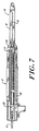
- FIGURE 7 is a sectional view of the electrosurgical tool of FIGURE 4 at lines B-B in an embodiment which does not include a surgical staple cartridge.
- FIGURE 8 is a schematic view of an electrosurgical clip application device employed in an impedance feedback electrosurgical system according to the invention.
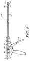
- FIGURE 9 is a side, partially cut-a-way view of the electrosurgical clip applicating device of FIGURE 8.
- FIGURE 10 is a schematic view showing a forward, clip deploying portion of a bipolar electrosurgical clip applicating device employed in an impedance feedback electrosurgical system according to the invention.
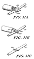
- FIGURES 11A through 11C schematically illustrate the sequence in which a surgical clip is applied using the tool of FIGURE 8.
- FIGURE 1 illustrates an impedance feedback electrosurgical system 100 constructed according to the present invention and in use with an electrosurgical tool 104.
- the system 100 includes an electrosurgical tool 104 which is connected in circuit to a power source, shown preferably as an RF generator 106.
- the tool 104 has an active electrode 108 which operates as a cutting edge and delivers electrosurgical energy to tissue 102.
- the active electrode 108 is connected to the positive pole of the electrosurgical energy supply, illustrated as an RF generator 106, through a power supply line 110.
- a return electrode 112 is also associated with the tool 104 and is connected to the negative pole of the electrosurgical supply 106 via a feedback line 114.
- An impedance monitor 116 - preferably having a programmable CPU - connects in circuit with the electrodes 108 and 112 to measure tissue impedance and to generate a signal representative of tissue impedance which is conveyed to a power control module 118 through a signal line 120.
- the power control module 118 regulates the electrosurgical energy generated from the RF generator 106 through a control line 121 such that the impedance measured by the impedance monitor 116 remains within a preselected range.
- the system preferably includes an activation switch 122 which a user can selectively operate to control the flow of energy to the delivery electrode 108.
- force can be applied to the tool 104 when the active electrode 108 contacts the tissue 102 to make an incision.
- Electrosurgical energy applied through tool 104 heats the cells in contact with the electrodes to provide a clean incision.
- the electrosurgical energy applied through the tool 104 also cauterizes tissue to minimize or eliminate any associated bleeding. Without the delivery of electrosurgical energy, e.g., RF energy, through active electrode 108, the surgical incision would be less effective as it would rely solely on the mechanical sharpness of the cutting blade.
- tissue impedance is maintained within a preselected range.
- a measurable current is conveyed through the return electrode 112 for use by impedance monitor 116, where tissue impedance is determined.
- the impedance monitor measures this as an increase in tissue resistance (i.e., impedance) and conveys a signal representative of the measured impedance to the control module 118, which in turn makes any necessary increase in the voltage conveyed to the active electrode to maintain tissue impedance within a desired range.
- the power control module 118 decreases the applied electrosurgical energy to maintain tissue impedance in the desired range.
- this electrosurgical energy is in the radio frequency range, and the tissue impedance ranges between about 20 and 500 Ohms.
- Impedance can be determined using a circuit 140 such as that shown in FIGURE 2, which is illustrative and can be altered in any number of ways to function equivalently.
- Circuit 140 includes an RF generator 106 in circuit with a voltage sensor 142, a current sensor 144, and electrodes 146 and 148.
- the voltage sensor 142 measures the voltage differential between locations 150 and 152
- the current sensor 144 measures the current between the same points.
- the electrodes 146 and 148 can represent, respectively, the active electrode 108 and return electrode 112 of FIGURE 1.
- FIGURE 2 Also shown in FIGURE 2 are three representative currents, i, i 1 , and i 2 , where the current i is the current at a location immediately after the generator 106, and the currents i 1 and i 2 are currents at the respective localities after the split at location 150,
- the resistance associated with the voltage sensor 142 is relatively high as compared to the rest of the circuit 140 and thus the current i is approximately equal to the current i 1 , which can be measured.
- the resistance associated with the current sensor 144 is relatively low as compared to the rest of the circuit 140 and thus the voltage difference between locations 150 and 152 is essentially unaffected by the current sensor 144.
- the voltage differential between localities 150 and 152 is the same as the voltage across the electrodes 146 and 148. Since the current i is known by measuring the current i 1 , a resistance between the electrodes 146 and 148 is also known. This resistance would be representative of the tissue impedance as described in FIGURE 1.
- the impedance monitor 116 of FIGURE 1 (not shown in FIGURE 2) preferably is in circuit with the sensors 142 and 144 to divide the measured voltage by the measured current and to determine tissue impedance. A tissue impedance signal is then generated and transmitted to the power control module of FIGURE 1 (not shown in FIGURE 2) to regulate the applied electrosurgical energy, thereby changing the voltage measured at the voltage sensor 142 and the current measured by the current sensor 144. In this fashion, the measured tissue impedance can be monitored and controlled to within a preselected range.
- tissue impedance e.g., corresponding to the resistance measurable in the circuit 140 of FIGURE 2
- the tissue impedance monitor 116 Tissue cells are most effectively heated and cauterized by RF energy when the impedance is kept to within a preferred electrosurgical range , e.g., 20 to 500 Ohms.
- tissue impedance is maintained within this range and the active electrode incises and cauterizes tissue most effectively with less chance of burning tissue.
- the tissue impedance is a factor of the surface area of the electrodes and distance between electrodes as well as the conductivity of the tissue and the changes created by the heating.
- the invention is able to maintain a desired tissue impedance independent of the speed with which an electrosurgical tool is used during surgery because impedance feedback is monitored and controlled automatically. Regardless of the speed at which the tool is manipulated, the effective application and beneficial usage of the electrosurgical energy remains substantially the same. If the tool is manipulated at a faster speed, the tissue impedance will measurably decrease and more energy will automatically be applied to tissue through the delivery electrode.
- FIGURES 3 through 7 illustrate an embodiment of the invention in which an electrosurgical cutting tool 10 is used with the impedance feedback system of the invention.
- Cutting tool 10 is a linear cutting tool comprising a housing 12 including a handle portion 14. Adjacent handle portion 14 is cutting template element 16 which includes a first tyne 18 and a second tyne 20. The two tynes 18, 20 of cutting template element 16 are substantially parallel and define a tissue engaging space 22 into which is inserted the tissue or organ to be incised.
- the surgical tool 10 includes a lever 24 which facilitates the movement of an active electrode, which may take the form of a cutting blade 34, along a predetermined path.
- FIGURE 3 further illustrates an electrosurgical generator 26 which serves as an energy source from which electrical current, preferably in the radio frequency range, is communicated to the cutting tool through insulated wire 28 and connector 63.
- Insulated wire 30 communicates through connector 31 and return wire 33 to a conductive portion of tyne 20 which serves as the ground or return electrode.
- a power switch 32 preferably in the form of a foot petal, may be used to break or close the generator 26 circuitry and thus inhibit or transmit the power supplied to the cutting tool.
- a power switch may be disposed on a portion of the cutting tool such as the housing 12.
- the circuit representing the power generator 26, the active electrode (e.g., blade 34), the return wire electrode, and the control module 26a, and impedance monitor 26b is electrically isolated to control the application of surgical energy by the tool.
- the control module 26a can regulate the electrosurgical energy delivered to the cutting blade 34, according to the measured tissue impedance determined by the impedance monitor 26b.
- the impedance monitor generates a signal representative of tissue impedance by quantifying the current received at the return electrode, which is a conductive portion of the tyne 20.
- the tissue impedance signal is communicated to the control module which in turn adjusts the applied electrosurgical energy to maintain a measured tissue impedance within a preselected range. Accordingly, electrosurgical power adjustments are made automatically to maintain a skin or tissue impedence to within a safe and operable range, independent of the speed and operator technique in using the tool 10.
- the range of measured tissue impedance is between 20 and 500 Ohms.
- tissue incisions occur with effective cell heating, and further the tissue is cauterized, without burning, to prevent or minimize bleeding.
- control module 26a and impedance monitor 26b are shown connected to the power generator 26, it should be apparent that their specific location is irrelevant as long as they permit the simultaneous control and measurement of tissue impedance during the operation of the tool 10. They can thus be easily located on the tool 10.
- Blade 34 of tool 10 preferably is able to be retracted when not in use, and moved forward along a cutting path to effect cutting of tissue.
- the energy requirements of the electrosurgical tool of the present invention are dynamic and depend to a great extent upon the impedance values of the tissue encountered by the active electrode, e.g, blade 34, during cutting procedures.
- the impedance of tissue varies among tissue types and the amount of blood present in or around the tissue.
- the amount of current delivered by the tool to the tissue is a function of the impedance of the tissue. Where tissue contacted has a lower impedance value, less electrosurgical energy will be delivered to the blade 34 by operation of the impedance monitor 26b and control module 26a, and, conversely, more electrosurgical energy will be delivered to the blade 34 when the tissue has a higher impedance value.
- the amount of current delivered to tissue ranges between about 0.5 and 2.0 amps.
- the voltage applied to the tissue between the blade and the return electrode typically is between about 50 to 100 volts rms. These values are typical and are varied automatically to maintain a nearly constant current in the tissue during operation of the tool 10.
- Surgical tool 10 is particularly well adapted for use in surgical procedures which require transection of an organ such as the intestine.
- tissue e.g., intestine
- the blade is moved forward along the longitudinal axis x of tynes 18 and 20 by movement of lever 24. As the blade moves forward, it passes through the tissue causing it to be severed.
- electrical energy e.g., radio frequency energy
- the electrosurgical current is communicated from the blade 34 to the tissue adjacent the blade and in the vicinity of the incision. Current should be delivered through the blade to the tissue during the entire cutting procedure.
- Electrosurgical energy is delivered through the blade to adjacent tissue to allow for more effective cutting action, and to promote cauterization and/or tissue fusion which effectively eliminates all or substantially all bleeding which results from the incision.
- the cauterization and/or fusion effect imparted to tissue minimizes blood loss and increases the safety of the surgical procedure as cauterization occurs at substantially the same time that the incision is made.
- the speed at which the incision is made is generally irrelevant since the control module 26a will vary the applied energy to maintain a nearly constant tissue impedance.
- the electrosurgical tool 10 also includes a staple cartridge 38 which houses a supply of surgical staples to be supplied adjacent the incision.
- the staples may be deployed in one or more linear rows on either side of the incision to assist in closing the incision and sealing the severed end of the organ.
- the staples are deployed nearly simultaneously with the cutting action of the blade and the tissue fusion effect imparted by the electrical energy.
- housing 12 and cartridge 38 may be made from or coated with various non-conducting polymers.
- the conductive components of the tool may be made of various metals, including surgical grade stainless steel and aluminum.
- FIGURES 8 through 10 illustrate other electrosurgical tools that may be used with the impedance feedback system of the invention.
- FIGURES 8 and 9 illustrate an electrosurgical clip applicating device 210 comprising a handle portion 212 having a trigger mechanism 214. Adjacent the handle is an elongate member 216 which houses a supply of surgical clips (not shown) as well as an actuating mechanism, described below, which assists in deploying the clips.
- the handle 212 also includes an electrical connector port 218 which is connected to duplex insulated wire 220, comprising an internal active wire and an internal return wire which, respectively, communicate electrosurgical energy to and from generator 226.
- the actuating mechanism preferably includes an actuating rod 221 which communicates with the trigger mechanism 214 through a catch 219 which mounts within groove 217 of trigger 214.
- Actuating rod 221 also communicates with paired clamping jaws 222a, 222b which extend from a distal end of barrel 216.
- the clamping jaws 222a, 222b are adapted to engage and deploy a surgical clip 224.
- Surgical clips can be deployed by activation of the trigger mechanism 214, causing actuating rod 221 to move backwards (toward the handle 212) while closing clamping jaws 222a, 222b together.
- clamping jaws 222a, 222b When the clamping jaws 222a, 222b are closed, the surgical clip 224 disposed between the jaws is clamped about a duct or vessel. Once a clip is deployed, a new clip may be positioned between clamping jaws 222a, 222b either automatically or manually.
- An impedance and power control subsystem 227 functions like the combination of impedance monitor 116 and power control module 118 described in FIGURE 1. Accordingly, subsystem 227 measures the tissue impedance and regulates the power applied to the tool 216 via the active wire of duplex wire 220.
- subsystem 227 is illustrated to be located with the generator 226, it is understood that its components and functions can easily be implemented at other locations, most readily within the tool 210.
- duplex port 218 communicates with internally conductive duplex wiring 225 which extends into the clipping device 210.
- One of the two conductive wires within duplex wire 225 is an active wire connected to the active wire of duplex wire 220 and is attached to a conductive portion of the activating mechanism which is in electrical communication with surgical clip 224 to be deployed, thereby functioning as the active electrode.
- the embodiment illustrated in FIGURE 9 is configured such that the active wire 225 terminates in a connection point 228, which is in electrical communication with the surgical clip 224, and electrically isolated from the clamping jaws 222a, 222b.
- the other wire within the duplex wire 225 is a return wire and is attached to a conductive portion of the clamping jaws 222a and 222b.
- the conductive portion is electrically isolated from the active electrode, i.e., the surgical clip 224, and functions as the return electrode to the negative pole of the power generator 226.
- duplex wires 225 and 220 form an isolated circuit with the generator 226, the impedance and power control subsystem 227, the return electrode on the clamping jaws 222a and 222b, the active electrode 224, and the tissue when the tool 210 is in operation.
- the active wire of duplex wire 225 may attach to actuating rod 221 which is made from a conductive material and which is in electrical communication with clamping jaws 222a, 222b.
- the portions of the clipping device 210 which are in electrical communication with the active wire of duplex wire 225 e.g., actuating rod 221 and/or clamping jaws 222a, 222b) preferably are electrically isolated from the remainder of the tool.
- the return wire of duplex wire 225 in this configuration is then connected to a separate return electrode (not shown) arranged on the tool 210 such that it contacts the tissue during operation of the tool 210 and functions as the return electrode to the negative pole of the generator 226.
- current Upon activating the delivery of current to tool 210, for example by activating switch 230, current will be delivered through the duplex wire 225 and communicated to the active electrode, i.e., the surgical clip 224, through actuating rod 221 and/or clamping jaws 222a, 222b.
- the return electrode receives the electrosurgical energy transmitted through the tissue from the active electrode.
- FIGURE 10 illustrates an alternative clip applying tool which can be used with the present invention.
- Reference numeral 215 represents a forward portion of the barrel 216 which is adapted to receive dual pairs of clamping jaws 240a, 240b and 242a, 242b.
- the clamping jaws 240a, 240b and 242a, 242b each communicate with their respective actuating mechanisms (not shown) which are electrically isolated from each other.
- Surgical clips 244 and 246 are shown positioned within jaws 240a, 240b and 242a, 242b.
- An insulated wire 248 functions like the active wire of duplex wire 220 shown in FIGURE 8 and communicates electrosurgical energy from generator 226 to clamping jaws 242a, 242b (or, alternatively, to the actuating mechanism associated with clamping jaws 242a, 242b).
- Wire 252 serves as a return wire which communicates between jaws 240a, 240b (or the actuating mechanism associated with jaws 240a, 240b).
- jaws 240a, 240b and 242a, 242b close together to deploy clips 244 and 246.
- a control switch is activated to deliver electrical current to the actuating mechanism associated with jaws 242a, 242b and/or directly to jaws 242a, 242b, and hence to clip 246, which functions as the active electrode.
- clip 246 contacts tissue, current is conveyed to the tissue causing the tissue and clip to be fused together.
- the electrosurgical energy also promotes tissue-to-tissue fusion.
- the applied current is returned to generator 226 through clamping jaws 240a, and 240b, and wire 252.
- Generator 226 supplies electrosurgical energy to the clipping device 210 in the manner described above.
- the generator is a voltage determinative, low source impedance generator which provides radio frequency energy.
- a suitable generator can supply up to 2 amps of current and has an impedance value of less than 10 ohms. Further details regarding the energy requirements of tool 210 are discussed above with respect to cutting tool 10.
- FIGURES 11A, 11B and 11C illustrate the manner in which surgical clips of FIGURES 8-10 are deployed.
- a vessel 232 to be ligated is disposed between clamping jaws 222a, 222b and surgical clip 224.
- the clamping jaws move together as. shown in Figure 11B, causing surgical clip 224 to close upon vessel 232.
- the clip 224 remains adhered to the vessel 232 as illustrated in FIGURE 11C.
- electrosurgical energy is delivered through the clip 224, which functions as the active electrode. Current is maintained for a suitable period of time, usually 5 to 15 seconds, to enable tissue-to-clip and tissue-to-tissue fusion to occur.
- a return electrode isolated from and disposed on the clamping jaws 222a and 222b (not shown) communicates with the generator through a return wire to complete the circuit with the vessel 232.
- the activating mechanism of clip activator 210 preferably is made of a conductive material which has a relatively high tensile strength. Exemplary materials include surgical grade stainless steel and aluminum. Clamping jaws 222a, 222b likewise are made of a surgically compatible, conductive material suitable to enable current to be communicated through the clamping jaws 222a, 222b to clip 224.
- the surgical clips 224 used with the clipping device of the invention may be with a variety of constructions and may be made of variety of conductive, surgically compatible materials which are well known in the art. As illustrated the surgical clip may be substantially U- or V-shaped, but various other shapes or constructions are possible as well.
- the handle portion 212, trigger 214, and the barrel 216 are electrically isolated from the remainder of the device.
- these components are made of, or are coated with, non-conductive materials such as suitable polymers.
- tool 210 The construction and operation of tool 210 is further described in copending parent application serial number 786,574, filed November 1, 1992.
- the scope of the present invention encompasses electrosurgical tools having constructions other than those specifically described herein.
- the present invention is potentially applicable to any electrosurgical device utilized in an impedance feedback electrosurgical system according to the invention in which electrosurgical energy is delivered through the device to tissue in contact with the device.
Abstract
Description
- The present invention relates to electrosurgical tools which are adapted to deliver electrosurgical energy to tissue.
- Surgical procedures often require incisions to be made in human tissue. Such procedures typically require the application of force to a surgical tool having one or more sharp, tissue-contacting edges, and usually create bleeding at the site of the incision. The ease with which the tool makes the incision and the prompt control or elimination of the bleeding thereby created is of paramount importance to the success and safety of the procedure.
- Currently known surgical cutting devices utilize different techniques to make incisions and to control or eliminate bleeding. One known device is the Proximate Linear Cutter available from the Ethicon, Inc. of Cincinnati, Ohio.
- This device is specifically adapted to make an incision in tissue or an organ such as the intestine. The device engages a portion of the tissue or organ between two tyne-like members. To effect cutting, a blade mounted on one of the tynes travels along a predetermined path, thereby making a linear incision through the tissue or organ. Surgical staples are deployed by the cutting device on either side of the incision, resulting in the separation of the organ into two segments, each of which is sealed adjacent to the incision by surgical staples. Despite the use of surgical staples and the precise cutting of the tissue, bleeding is not entirely eliminated and separate cauterization procedures must often be utilized to control or stop bleeding.
- Surgical devices also are known which utilize electrical current in the form of radio frequency (RF) energy to incise and to cauterize tissue to control bleeding. U.S. Patent No. 4,651,734 discloses a surgical scalpel modified to include an electrode. This scalpel has the ability to cut tissue and, when properly positioned, to cauterize tissue following a cutting procedure. Such a surgical tool is useful but does not simultaneously cut and cauterize tissue. The separate cauterization procedure which must be utilized is relatively time consuming and may result in unnecessary bleeding. Moreover, such a scalpel is not well suited to many surgical procedures such as the transection of the intestine.
- Typically, the surgical tools which employ RF energy to cut and cauterize do so with a constant energy supply. Because of this, the tool must be carefully controlled during surgery to ensure that the correct amount of RF energy is applied to the target tissue. For example, if a surgical tool delivers RF energy through a cutting edge to tissue at a magnitude sufficient to cut or cauterize tissue, tissue burns could result if the cutting edge contacts the tissue for too long a period. Similarly, if the cutting edge is moved too quickly through tissue, the optimal amount of energy may not be applied to the tissue. Thus, if not used properly, currently known electrosurgical tools may not take full advantage of the benefits of electrosurgery.
- Nardella, "Radio Frequency Energy and Impedance Feedback", SPIE vol. 1068, Catheter-Based Sensing and Imaging Technology (1989), pgs. 42 - 48, describes in general terms the intravascular application of RF energy to unblock blood vessels occluded by plaque or thrombi. The disclosed system is applied to catheters that are used for cardiac ablation, thermal balloon angioplasty, and recanalization.
- U.S. 4,474,179 discloses a high frequency coagulation device that measures a differential quotient in the form of a change in impedance over time, and adjusts the power output of the device in accordance with the differential quotient.
- GB 2213381 discloses a surgical diathermy apparatus that utilizes highfrequency alternating current to perform electro-coagulation or surgery. Impedance values of the total circuit are calculated in accordance with sensed instantaneous voltage and current values. An automatic detector senses any impedance value above a pre-determined level, and is arranged to produce a warning or control signal.
- U.S. 4,969,885 discloses a high frequency AC electro-surgery apparatus that is equipped with an automatic regulation loop for controlling the output voltage. A DC signal is generated that is proportional to a measure of the high frequency AC output voltage. The AC voltage at the output terminals corresponds to a desired value set by a reference voltage signal.
- The invention, therefore, provides an impedance feedback electrosurgical system in accordance with
claim 1. - Accordingly, an object of this invention is to provide an electrosurgical system which enables electrosurgical tools to conveniently and safely incise and/or penetrate human tissue with controlled and precise application of RF energy. It is another object of the invention to provide a surgical tool which has improved cutting capability and which decreases some of the risk associated with surgery by minimizing the amount of bleeding resulting from incisions and tissue penetration. Another object is to provide a surgical tool which is adapted to simultaneously cut and cauterize tissue. Other objects of the invention will be apparent upon reading the disclosure which follows.
- The invention attains the aforementioned objects by providing a system which measures tissue impedance as a feedback parameter from surgical tools that apply electrosurgical energy to tissue during surgery. The system is useful with a variety of electrosurgical devices including cutting tools and surgical clip applying devices.
- In one aspect, an impedance feedback electrosurgical system constructed in accordance with the invention includes an electrosurgical tool which is adapted to receive power from an electrosurgical power source and to deliver electrosurgical energy to tissue through an active electrode in contact with the tissue. A return or second electrode is also associated with the tool and is electrically insulated from the active electrode. Electrosurgical energy is thus communicated from the active electrode, through the tissue, and to the return electrode.
- Preferably, an impedance monitoring device is in circuit with the active and return electrodes to measure the impedance of the target tissue, which can be ascertained based upon the voltage and current of the applied energy. A power control module is also in circuit with the impedance monitoring device to regulate the electrosurgical energy delivered to the tissue through the active electrode by responding to a signal representative of tissue impedance generated by the impedance monitor. The system is able to control the electrosurgical energy applied to the tissue by maintaining a measured tissue impedance within a preselected range. The desired tissue impedance range is preferably between about 20 to 500 Ohms.
- In other aspects, the impedance feedback electrosurgical system has control circuitry to enable one to select the range at which the measured tissue impedance is maintained during surgery. One or more acoustical warning devices are preferably connected in circuit with the system to warn a user that measured impedance is outside the range and to inform the user of the measured impedance.
- In yet another aspect, the impedance feedback electrosurgical system regulates the energy delivered to the tissue by varying the applied voltage of the electrosurgical power source.
- In still another aspect, the impedance feedback electrosurgical system controls the electrosurgical energy delivered through the delivery electrode to the tissue by an activation system. An operator can inhibit or transmit the electrosurgical energy delivered to the tissue by selectively operating the activation system, which operates much like an electrical switch.
- The advantages of the electrosurgical system of the invention are several. First and foremost, by maintaining a preselected range of tissue impedance, electrosurgical energy is applied to the target tissue at a preselected level independent of the speed and operation of the tool as used by an operator or surgeon. Furthermore, when an electrosurgical tool is adapted to a system constructed in accordance with the invention, the system will inherently monitor the tool's passage through different tissue types and certain tissue barriers. For example, once the tool penetrates the abdominal wall, the current density at the active electrode will increase at the areas in contact with the electrode, and thus the applied electrosurgical energy will be automatically lowered to thereby protect that tissue from receiving excessive or unwanted RF energy.
- The electrosurgical energy applied to an active electrode in accordance with the invention also improves the mechanical cutting ability of the tool, and more importantly, facilitates the cauterization and/or fusion of the tissue following the incision. The application of radio frequency energy, for example, to the tissue allows the simultaneous cutting and cauterization of the tissue with an effective consistency independent of a user's technique. Moreover, the use of electrosurgical energy to penetrate tissue can eliminate the need for a conventional, sharpened cutting blade. A conductive electrode can deliver sufficient levels of electrosurgical energy to tissue to effectively incise tissue. The electrosurgical energy also enhances other electrosurgical tools such as clip applying devices.
- A method for controlling the level of electrosurgical energy applied to tissue by an electrosurgical tool is also provided. These and other aspects of the invention are evident in the description which follows and in the accompanying drawings.
- FIGURE 1 schematically illustrates an impedance feedback electrosurgical system constructed in accordance with the invention and in use with an energy supply source and an electrosurgical tool.
- FIGURE 2 schematically illustrates an electrical circuit which can be used to measure tissue impedance.
- FIGURE 3 schematically illustrates a surgical cutting tool employed in an impedance feedback electrosurgical system according to the invention, including a supply source of electrosurgical energy.
- FIGURE 4 is an exploded side view of the electrosurgical cutting tool illustrated in FIGURE 3.
- FIGURE 5 is a sectional view of the electrosurgical tools of FIGURE 4 at lines A-A.
- FIGURE 6 is a sectional view of the electrosurgical tool of FIGURE 4 at lines B-B.
- FIGURE 7 is a sectional view of the electrosurgical tool of FIGURE 4 at lines B-B in an embodiment which does not include a surgical staple cartridge.
- FIGURE 8 is a schematic view of an electrosurgical clip application device employed in an impedance feedback electrosurgical system according to the invention.
- FIGURE 9 is a side, partially cut-a-way view of the electrosurgical clip applicating device of FIGURE 8.
- FIGURE 10 is a schematic view showing a forward, clip deploying portion of a bipolar electrosurgical clip applicating device employed in an impedance feedback electrosurgical system according to the invention.
- FIGURES 11A through 11C schematically illustrate the sequence in which a surgical clip is applied using the tool of FIGURE 8.
- FIGURE 1 illustrates an impedance
feedback electrosurgical system 100 constructed according to the present invention and in use with anelectrosurgical tool 104. Thesystem 100 includes anelectrosurgical tool 104 which is connected in circuit to a power source, shown preferably as anRF generator 106. Thetool 104 has anactive electrode 108 which operates as a cutting edge and delivers electrosurgical energy totissue 102. Theactive electrode 108 is connected to the positive pole of the electrosurgical energy supply, illustrated as anRF generator 106, through apower supply line 110. Areturn electrode 112 is also associated with thetool 104 and is connected to the negative pole of theelectrosurgical supply 106 via afeedback line 114. An impedance monitor 116 - preferably having a programmable CPU - connects in circuit with theelectrodes power control module 118 through asignal line 120. Thepower control module 118 regulates the electrosurgical energy generated from theRF generator 106 through acontrol line 121 such that the impedance measured by the impedance monitor 116 remains within a preselected range. Moreover, the system preferably includes anactivation switch 122 which a user can selectively operate to control the flow of energy to thedelivery electrode 108. - In operation, force can be applied to the
tool 104 when theactive electrode 108 contacts thetissue 102 to make an incision. Electrosurgical energy applied throughtool 104 heats the cells in contact with the electrodes to provide a clean incision. In the course of cutting, the electrosurgical energy applied through thetool 104 also cauterizes tissue to minimize or eliminate any associated bleeding. Without the delivery of electrosurgical energy, e.g., RF energy, throughactive electrode 108, the surgical incision would be less effective as it would rely solely on the mechanical sharpness of the cutting blade. - As noted, tissue impedance is maintained within a preselected range. Upon delivery of electrosurgical energy to
tissue 102 through theactive electrode 108, a measurable current is conveyed through thereturn electrode 112 for use byimpedance monitor 116, where tissue impedance is determined. Accordingly, as more tissue comes into contact with theactive electrode 108, the current at thereturn electrode 112 decreases. The impedance monitor measures this as an increase in tissue resistance (i.e., impedance) and conveys a signal representative of the measured impedance to thecontrol module 118, which in turn makes any necessary increase in the voltage conveyed to the active electrode to maintain tissue impedance within a desired range. Where theimpedance monitor 116 detects a decrease in tissue impedance below the desired minimum, thepower control module 118 decreases the applied electrosurgical energy to maintain tissue impedance in the desired range. Preferably, this electrosurgical energy is in the radio frequency range, and the tissue impedance ranges between about 20 and 500 Ohms. - Impedance can be determined using a
circuit 140 such as that shown in FIGURE 2, which is illustrative and can be altered in any number of ways to function equivalently.Circuit 140 includes anRF generator 106 in circuit with avoltage sensor 142, acurrent sensor 144, andelectrodes voltage sensor 142 measures the voltage differential betweenlocations current sensor 144 measures the current between the same points. Theelectrodes active electrode 108 and return electrode 112 of FIGURE 1. Also shown in FIGURE 2 are three representative currents, i, i1, and i2, where the current i is the current at a location immediately after thegenerator 106, and the currents i1 and i2 are currents at the respective localities after the split atlocation 150, - The resistance associated with the
voltage sensor 142 is relatively high as compared to the rest of thecircuit 140 and thus the current i is approximately equal to the current i1, which can be measured. On the other hand, the resistance associated with thecurrent sensor 144 is relatively low as compared to the rest of thecircuit 140 and thus the voltage difference betweenlocations current sensor 144. - In
circuit 140, therefore, the voltage differential betweenlocalities electrodes electrodes sensors voltage sensor 142 and the current measured by thecurrent sensor 144. In this fashion, the measured tissue impedance can be monitored and controlled to within a preselected range. - The measurement of tissue impedance, e.g., corresponding to the resistance measurable in the
circuit 140 of FIGURE 2, is readily understood by one of ordinary skill in the art. When the current through the tissue decreases for a given applied voltage, the tissue impedance increases and is readily measured by theimpedance monitor 116. Tissue cells are most effectively heated and cauterized by RF energy when the impedance is kept to within a preferred electrosurgical range , e.g., 20 to 500 Ohms. By increasing or decreasing the amount of electrosurgical energy applied to the tissue through the active electrode, tissue impedance is maintained within this range and the active electrode incises and cauterizes tissue most effectively with less chance of burning tissue. The tissue impedance is a factor of the surface area of the electrodes and distance between electrodes as well as the conductivity of the tissue and the changes created by the heating. - Additionally, the invention is able to maintain a desired tissue impedance independent of the speed with which an electrosurgical tool is used during surgery because impedance feedback is monitored and controlled automatically. Regardless of the speed at which the tool is manipulated, the effective application and beneficial usage of the electrosurgical energy remains substantially the same. If the tool is manipulated at a faster speed, the tissue impedance will measurably decrease and more energy will automatically be applied to tissue through the delivery electrode.
- FIGURES 3 through 7 illustrate an embodiment of the invention in which an
electrosurgical cutting tool 10 is used with the impedance feedback system of the invention. Cuttingtool 10 is a linear cutting tool comprising ahousing 12 including ahandle portion 14.Adjacent handle portion 14 is cuttingtemplate element 16 which includes afirst tyne 18 and asecond tyne 20. The twotynes template element 16 are substantially parallel and define atissue engaging space 22 into which is inserted the tissue or organ to be incised. In a preferred embodiment, thesurgical tool 10 includes alever 24 which facilitates the movement of an active electrode, which may take the form of acutting blade 34, along a predetermined path. - FIGURE 3 further illustrates an
electrosurgical generator 26 which serves as an energy source from which electrical current, preferably in the radio frequency range, is communicated to the cutting tool through insulatedwire 28 and connector 63.Insulated wire 30 communicates throughconnector 31 andreturn wire 33 to a conductive portion oftyne 20 which serves as the ground or return electrode. A power switch 32, preferably in the form of a foot petal, may be used to break or close thegenerator 26 circuitry and thus inhibit or transmit the power supplied to the cutting tool. Alternatively, a power switch may be disposed on a portion of the cutting tool such as thehousing 12. - The circuit representing the
power generator 26, the active electrode (e.g., blade 34), the return wire electrode, and thecontrol module 26a, andimpedance monitor 26b is electrically isolated to control the application of surgical energy by the tool. Thecontrol module 26a can regulate the electrosurgical energy delivered to thecutting blade 34, according to the measured tissue impedance determined by theimpedance monitor 26b. As noted, the impedance monitor generates a signal representative of tissue impedance by quantifying the current received at the return electrode, which is a conductive portion of thetyne 20. The tissue impedance signal is communicated to the control module which in turn adjusts the applied electrosurgical energy to maintain a measured tissue impedance within a preselected range. Accordingly, electrosurgical power adjustments are made automatically to maintain a skin or tissue impedence to within a safe and operable range, independent of the speed and operator technique in using thetool 10. - In particular, for radio frequency energy, the range of measured tissue impedance is between 20 and 500 Ohms. When operating in this range, tissue incisions occur with effective cell heating, and further the tissue is cauterized, without burning, to prevent or minimize bleeding.
- Although the
control module 26a andimpedance monitor 26b are shown connected to thepower generator 26, it should be apparent that their specific location is irrelevant as long as they permit the simultaneous control and measurement of tissue impedance during the operation of thetool 10. They can thus be easily located on thetool 10. -
Blade 34 oftool 10 preferably is able to be retracted when not in use, and moved forward along a cutting path to effect cutting of tissue. - The energy requirements of the electrosurgical tool of the present invention are dynamic and depend to a great extent upon the impedance values of the tissue encountered by the active electrode, e.g,
blade 34, during cutting procedures. The impedance of tissue varies among tissue types and the amount of blood present in or around the tissue. The amount of current delivered by the tool to the tissue is a function of the impedance of the tissue. Where tissue contacted has a lower impedance value, less electrosurgical energy will be delivered to theblade 34 by operation of theimpedance monitor 26b andcontrol module 26a, and, conversely, more electrosurgical energy will be delivered to theblade 34 when the tissue has a higher impedance value. Generally, the amount of current delivered to tissue ranges between about 0.5 and 2.0 amps. The voltage applied to the tissue between the blade and the return electrode typically is between about 50 to 100 volts rms. These values are typical and are varied automatically to maintain a nearly constant current in the tissue during operation of thetool 10. -
Surgical tool 10 is particularly well adapted for use in surgical procedures which require transection of an organ such as the intestine. In operation, the tissue (e.g., intestine) is placed withinspace 22 defined bytynes tynes lever 24. As the blade moves forward, it passes through the tissue causing it to be severed. Simultaneously, electrical energy (e.g., radio frequency energy), which may be activated for example by foot switch 32, is delivered to the tool. The electrosurgical current is communicated from theblade 34 to the tissue adjacent the blade and in the vicinity of the incision. Current should be delivered through the blade to the tissue during the entire cutting procedure. - The application of electrical energy in this manner provides two advantages. Electrosurgical energy is delivered through the blade to adjacent tissue to allow for more effective cutting action, and to promote cauterization and/or tissue fusion which effectively eliminates all or substantially all bleeding which results from the incision. The cauterization and/or fusion effect imparted to tissue minimizes blood loss and increases the safety of the surgical procedure as cauterization occurs at substantially the same time that the incision is made. Furthermore, the speed at which the incision is made is generally irrelevant since the
control module 26a will vary the applied energy to maintain a nearly constant tissue impedance. - In a preferred embodiment of the invention, the
electrosurgical tool 10 also includes astaple cartridge 38 which houses a supply of surgical staples to be supplied adjacent the incision. The staples may be deployed in one or more linear rows on either side of the incision to assist in closing the incision and sealing the severed end of the organ. The staples are deployed nearly simultaneously with the cutting action of the blade and the tissue fusion effect imparted by the electrical energy. - One skilled in the art will appreciated that a variety of materials are well suited for the manufacture of the
electrosurgical tool 10 shown in FIGURES 2-6. For example,housing 12 andcartridge 38 may be made from or coated with various non-conducting polymers. The conductive components of the tool may be made of various metals, including surgical grade stainless steel and aluminum. -
Tool 10 is further described in copending U.S. patent application serial numbers 786,572, filed November 1, 1991. - FIGURES 8 through 10 illustrate other electrosurgical tools that may be used with the impedance feedback system of the invention. FIGURES 8 and 9 illustrate an electrosurgical
clip applicating device 210 comprising ahandle portion 212 having atrigger mechanism 214. Adjacent the handle is anelongate member 216 which houses a supply of surgical clips (not shown) as well as an actuating mechanism, described below, which assists in deploying the clips. Thehandle 212 also includes anelectrical connector port 218 which is connected to duplex insulatedwire 220, comprising an internal active wire and an internal return wire which, respectively, communicate electrosurgical energy to and fromgenerator 226. - An actuating mechanism adaptable for use with
tool 210 is illustrated in Figure 8. The actuating mechanism preferably includes anactuating rod 221 which communicates with thetrigger mechanism 214 through acatch 219 which mounts withingroove 217 oftrigger 214.Actuating rod 221 also communicates with paired clampingjaws barrel 216. The clampingjaws surgical clip 224. Surgical clips can be deployed by activation of thetrigger mechanism 214, causingactuating rod 221 to move backwards (toward the handle 212) while closingclamping jaws jaws surgical clip 224 disposed between the jaws is clamped about a duct or vessel. Once a clip is deployed, a new clip may be positioned between clampingjaws - An impedance and
power control subsystem 227 functions like the combination of impedance monitor 116 andpower control module 118 described in FIGURE 1. Accordingly,subsystem 227 measures the tissue impedance and regulates the power applied to thetool 216 via the active wire ofduplex wire 220. - Although the
subsystem 227 is illustrated to be located with thegenerator 226, it is understood that its components and functions can easily be implemented at other locations, most readily within thetool 210. -
Electrosurgical generator 226, shown in FIGURE 8, communicates withclipping device 210 throughconductive duplex wiring 220 which connects to the clipping device throughduplex port 218. As shown in FIGURE 9,duplex port 218 communicates with internallyconductive duplex wiring 225 which extends into theclipping device 210. One of the two conductive wires withinduplex wire 225 is an active wire connected to the active wire ofduplex wire 220 and is attached to a conductive portion of the activating mechanism which is in electrical communication withsurgical clip 224 to be deployed, thereby functioning as the active electrode. The embodiment illustrated in FIGURE 9 is configured such that theactive wire 225 terminates in aconnection point 228, which is in electrical communication with thesurgical clip 224, and electrically isolated from the clampingjaws duplex wire 225 is a return wire and is attached to a conductive portion of the clampingjaws surgical clip 224, and functions as the return electrode to the negative pole of thepower generator 226. With this arrangement, theduplex wires generator 226, the impedance andpower control subsystem 227, the return electrode on the clampingjaws active electrode 224, and the tissue when thetool 210 is in operation. - In an alternative embodiment (not illustrated), the active wire of
duplex wire 225 may attach to actuatingrod 221 which is made from a conductive material and which is in electrical communication with clampingjaws clipping device 210 which are in electrical communication with the active wire of duplex wire 225 (e.g., actuatingrod 221 and/or clampingjaws duplex wire 225 in this configuration is then connected to a separate return electrode (not shown) arranged on thetool 210 such that it contacts the tissue during operation of thetool 210 and functions as the return electrode to the negative pole of thegenerator 226. Upon activating the delivery of current totool 210, for example by activatingswitch 230, current will be delivered through theduplex wire 225 and communicated to the active electrode, i.e., thesurgical clip 224, throughactuating rod 221 and/or clampingjaws - FIGURE 10 illustrates an alternative clip applying tool which can be used with the present invention.
Reference numeral 215 represents a forward portion of thebarrel 216 which is adapted to receive dual pairs of clampingjaws jaws Surgical clips jaws - An
insulated wire 248 functions like the active wire ofduplex wire 220 shown in FIGURE 8 and communicates electrosurgical energy fromgenerator 226 to clampingjaws 242a, 242b (or, alternatively, to the actuating mechanism associated with clampingjaws 242a, 242b).Wire 252 serves as a return wire which communicates betweenjaws jaws jaws clips jaws 242a, 242b and/or directly tojaws 242a, 242b, and hence to clip 246, which functions as the active electrode. When theclip 246 contacts tissue, current is conveyed to the tissue causing the tissue and clip to be fused together. The electrosurgical energy also promotes tissue-to-tissue fusion. The applied current is returned togenerator 226 through clampingjaws wire 252. -
Generator 226 supplies electrosurgical energy to theclipping device 210 in the manner described above. Virtually any generator able to provide electrosurgical energy for medical applications may be used with the present invention. Preferably, the generator is a voltage determinative, low source impedance generator which provides radio frequency energy. Preferably, a suitable generator can supply up to 2 amps of current and has an impedance value of less than 10 ohms. Further details regarding the energy requirements oftool 210 are discussed above with respect to cuttingtool 10. - FIGURES 11A, 11B and 11C illustrate the manner in which surgical clips of FIGURES 8-10 are deployed. A
vessel 232 to be ligated is disposed between clampingjaws surgical clip 224. Upon activating the triggering mechanism, the clamping jaws move together as. shown in Figure 11B, causingsurgical clip 224 to close uponvessel 232. When the triggering action is completed theclip 224 remains adhered to thevessel 232 as illustrated in FIGURE 11C. While the clip is applied over the vessel, electrosurgical energy is delivered through theclip 224, which functions as the active electrode. Current is maintained for a suitable period of time, usually 5 to 15 seconds, to enable tissue-to-clip and tissue-to-tissue fusion to occur. A return electrode isolated from and disposed on the clampingjaws vessel 232. - The activating mechanism of
clip activator 210 preferably is made of a conductive material which has a relatively high tensile strength. Exemplary materials include surgical grade stainless steel and aluminum. Clampingjaws jaws surgical clips 224 used with the clipping device of the invention may be with a variety of constructions and may be made of variety of conductive, surgically compatible materials which are well known in the art. As illustrated the surgical clip may be substantially U- or V-shaped, but various other shapes or constructions are possible as well. - The
handle portion 212,trigger 214, and thebarrel 216 are electrically isolated from the remainder of the device. Preferably, these components are made of, or are coated with, non-conductive materials such as suitable polymers. - The construction and operation of
tool 210 is further described in copending parent application serial number 786,574, filed November 1, 1992. - It is to be understood that the scope of the present invention encompasses electrosurgical tools having constructions other than those specifically described herein. The present invention is potentially applicable to any electrosurgical device utilized in an impedance feedback electrosurgical system according to the invention in which electrosurgical energy is delivered through the device to tissue in contact with the device.
Claims (9)
- An impedance feedback electrosurgical system (100) for cutting and/or cauterizing tissue (102) comprising a bipolar electrosurgical device (10) having a cutting portion (34) including opposed, first (18) and second (20) tissue engaging surfaces defining a tissue engaging space (22) therebetween, wherein one of the first or second surfaces includes an active, energy delivering electrode (108), and the other of the first or second surfaces includes a return electrode (112) electrically insulated from the active, energy delivering electrode and being adapted to receive electrosurgical energy delivered by the active electrode (108) through tissue (102) disposed within the tissue engaging space (22);characterized by:power means (106), in electrical communication with the active (108) and return (112) electrodes, for supplying radio frequency energy to the electrosurgical device (10);power control means (118), in circuit with the electrosurgical, device,impedance measurement means (116) in electrical communication with the electrosurgical device (10) and the power means (106), the impedance measuring means having a first electrical connection that is coupled to the return electrode (112) for measuring the electrical impedance of the tissue (102) disposed within the tissue engaging space (22) based on current and voltage applied to the tissue, the impedance measurement means (116) generating a tissue impedance signal representative of tissue impedance; andthe impedance measurement means (116) and the power control means (118), regulate the electrosurgical energy delivered to the tissue (102) disposed within the tissue-engaging space (22) by the active, energy delivering electrode (108) in response to the impedance signal to maintain the tissue impedance within a preselected range.
- A system (100) as claimed in Claim 1 wherein the range of impedance values is between about 20 Ohms and about 500 Ohms.
- A system (100) as claimed in Claim 1 or Claim 2 wherein the power control means (118) regulates the energy applied to the active electrode (108) by varying the voltage applied thereto.
- A system (100) as claimed in any of Claims 1-3 further comprising activation means (32) for selectively activating the power means (106) to deliver electrosurgical energy to the active, energy delivering electrode (108).
- A system (100) as claimed in any of Claims 1-4 wherein the electrosurgical device (10) is an electrosurgical cutting device adapted to cut and substantially simultaneously cauterize the tissue (102) disposed in the tissue engaging space (22) located between the active (108) and return (112) electrodes.
- A system (100) as claimed in any of Claims 1-5 further including a cutting element (34) associated with one of the first (18) or second (20) tissue engaging surfaces, the cutting element being movable between a non-operative position within one of the first or second tissue engaging surfaces and an operative position.
- A system (100) as claimed in Claim 6 wherein the cutting element (34) is the energy delivering electrode (108).
- A system (100) as claimed in any of Claims 1-7 wherein the voltage delivered to the electrosurgical device (10) by the power means (106) is between about 50 volts and about 100 volts RMS.
- A system (100) as claimed in any of Claims 1-8 further comprising acoustical warning means, responsive to the tissue impedance signal generated by the impedance measurement means (116), for informing a user of a change in the measured tissue impedance or for alerting a user that the measured tissue impedance is outside of the preselected range.
Applications Claiming Priority (3)
| Application Number | Priority Date | Filing Date | Title |
|---|---|---|---|
| US5582793A | 1993-04-30 | 1993-04-30 | |
| US55827 | 1993-04-30 | ||
| PCT/US1994/004631 WO1994024951A1 (en) | 1993-04-30 | 1994-04-29 | Impedance feedback electrosurgical system |
Publications (3)
| Publication Number | Publication Date |
|---|---|
| EP0696182A1 EP0696182A1 (en) | 1996-02-14 |
| EP0696182A4 EP0696182A4 (en) | 1996-11-06 |
| EP0696182B1 true EP0696182B1 (en) | 2003-01-22 |
Family
ID=22000406
Family Applications (2)
| Application Number | Title | Priority Date | Filing Date |
|---|---|---|---|
| EP94915911A Expired - Lifetime EP0696181B1 (en) | 1993-04-30 | 1994-04-29 | Impedance feedback electrosurgical system |
| EP94914929A Expired - Lifetime EP0696182B1 (en) | 1993-04-30 | 1994-04-29 | Impedance feedback electrosurgical system |
Family Applications Before (1)
| Application Number | Title | Priority Date | Filing Date |
|---|---|---|---|
| EP94915911A Expired - Lifetime EP0696181B1 (en) | 1993-04-30 | 1994-04-29 | Impedance feedback electrosurgical system |
Country Status (7)
| Country | Link |
|---|---|
| EP (2) | EP0696181B1 (en) |
| JP (2) | JP3585491B2 (en) |
| AT (2) | ATE234047T1 (en) |
| AU (2) | AU684784B2 (en) |
| CA (2) | CA2161421C (en) |
| DE (2) | DE69432050T2 (en) |
| WO (2) | WO1994024949A1 (en) |
Families Citing this family (181)
| Publication number | Priority date | Publication date | Assignee | Title |
|---|---|---|---|---|
| US5807393A (en) * | 1992-12-22 | 1998-09-15 | Ethicon Endo-Surgery, Inc. | Surgical tissue treating device with locking mechanism |
| US5558671A (en) * | 1993-07-22 | 1996-09-24 | Yates; David C. | Impedance feedback monitor for electrosurgical instrument |
| US5403312A (en) * | 1993-07-22 | 1995-04-04 | Ethicon, Inc. | Electrosurgical hemostatic device |
| US5693051A (en) * | 1993-07-22 | 1997-12-02 | Ethicon Endo-Surgery, Inc. | Electrosurgical hemostatic device with adaptive electrodes |
| US5817093A (en) * | 1993-07-22 | 1998-10-06 | Ethicon Endo-Surgery, Inc. | Impedance feedback monitor with query electrode for electrosurgical instrument |
| US5688270A (en) * | 1993-07-22 | 1997-11-18 | Ethicon Endo-Surgery,Inc. | Electrosurgical hemostatic device with recessed and/or offset electrodes |
| US5709680A (en) * | 1993-07-22 | 1998-01-20 | Ethicon Endo-Surgery, Inc. | Electrosurgical hemostatic device |
| AU701320B2 (en) * | 1994-12-22 | 1999-01-28 | Ethicon Endo-Surgery, Inc. | Impedance feedback monitor with query electrode for electrosurgical instrument |
| CA2168404C (en) * | 1995-02-01 | 2007-07-10 | Dale Schulze | Surgical instrument with expandable cutting element |
| US5630426A (en) * | 1995-03-03 | 1997-05-20 | Neovision Corporation | Apparatus and method for characterization and treatment of tumors |
| US5599350A (en) * | 1995-04-03 | 1997-02-04 | Ethicon Endo-Surgery, Inc. | Electrosurgical clamping device with coagulation feedback |
| US5624452A (en) * | 1995-04-07 | 1997-04-29 | Ethicon Endo-Surgery, Inc. | Hemostatic surgical cutting or stapling instrument |
| US5707369A (en) * | 1995-04-24 | 1998-01-13 | Ethicon Endo-Surgery, Inc. | Temperature feedback monitor for hemostatic surgical instrument |
| WO1996034567A1 (en) * | 1995-05-02 | 1996-11-07 | Heart Rhythm Technologies, Inc. | System for controlling the energy delivered to a patient for ablation |
| US5827271A (en) * | 1995-09-19 | 1998-10-27 | Valleylab | Energy delivery system for vessel sealing |
| EP0979635A2 (en) | 1998-08-12 | 2000-02-16 | Origin Medsystems, Inc. | Tissue dissector apparatus |
| US7137980B2 (en) | 1998-10-23 | 2006-11-21 | Sherwood Services Ag | Method and system for controlling output of RF medical generator |
| US6558313B1 (en) | 2000-11-17 | 2003-05-06 | Embro Corporation | Vein harvesting system and method |
| DE10102254A1 (en) * | 2001-01-19 | 2002-08-08 | Celon Ag Medical Instruments | Device for the electrothermal treatment of the human or animal body |
| US6989010B2 (en) * | 2001-04-26 | 2006-01-24 | Medtronic, Inc. | Ablation system and method of use |
| US10835307B2 (en) | 2001-06-12 | 2020-11-17 | Ethicon Llc | Modular battery powered handheld surgical instrument containing elongated multi-layered shaft |
| US6802843B2 (en) | 2001-09-13 | 2004-10-12 | Csaba Truckai | Electrosurgical working end with resistive gradient electrodes |
| US6773409B2 (en) | 2001-09-19 | 2004-08-10 | Surgrx Llc | Surgical system for applying ultrasonic energy to tissue |
| US8075558B2 (en) | 2002-04-30 | 2011-12-13 | Surgrx, Inc. | Electrosurgical instrument and method |
| US7517349B2 (en) | 2001-10-22 | 2009-04-14 | Vnus Medical Technologies, Inc. | Electrosurgical instrument and method |
| US7189233B2 (en) | 2001-10-22 | 2007-03-13 | Surgrx, Inc. | Electrosurgical instrument |
| US7396336B2 (en) | 2003-10-30 | 2008-07-08 | Sherwood Services Ag | Switched resonant ultrasonic power amplifier system |
| US8182501B2 (en) | 2004-02-27 | 2012-05-22 | Ethicon Endo-Surgery, Inc. | Ultrasonic surgical shears and method for sealing a blood vessel using same |
| US7608073B2 (en) | 2004-07-09 | 2009-10-27 | Tyco Healthcare Group Lp | Energy based partial circumferential hemorrhoid repair device |
| DE102004041681A1 (en) | 2004-08-20 | 2006-02-23 | Celon Ag Medical Instruments | Device for the electrosurgical desquamation of body tissue |
| AU2005295010B2 (en) | 2004-10-08 | 2012-05-31 | Ethicon Endo-Surgery, Inc. | Ultrasonic surgical instrument |
| US9474564B2 (en) | 2005-03-31 | 2016-10-25 | Covidien Ag | Method and system for compensating for external impedance of an energy carrying component when controlling an electrosurgical generator |
| US20070191713A1 (en) | 2005-10-14 | 2007-08-16 | Eichmann Stephen E | Ultrasonic device for cutting and coagulating |
| US8734438B2 (en) | 2005-10-21 | 2014-05-27 | Covidien Ag | Circuit and method for reducing stored energy in an electrosurgical generator |
| US8406866B2 (en) | 2005-12-06 | 2013-03-26 | St. Jude Medical, Atrial Fibrillation Division, Inc. | System and method for assessing coupling between an electrode and tissue |
| BRPI0621018A2 (en) | 2005-12-06 | 2011-11-29 | St Jude Medical Atrial Fibrill Div | method and instrument for displaying catheter electrode-tissue contact in electro-anatomical mapping and navigation system |
| US10362959B2 (en) | 2005-12-06 | 2019-07-30 | St. Jude Medical, Atrial Fibrillation Division, Inc. | System and method for assessing the proximity of an electrode to tissue in a body |
| US8403925B2 (en) | 2006-12-06 | 2013-03-26 | St. Jude Medical, Atrial Fibrillation Division, Inc. | System and method for assessing lesions in tissue |
| US9492226B2 (en) | 2005-12-06 | 2016-11-15 | St. Jude Medical, Atrial Fibrillation Division, Inc. | Graphical user interface for real-time RF lesion depth display |
| US8603084B2 (en) | 2005-12-06 | 2013-12-10 | St. Jude Medical, Atrial Fibrillation Division, Inc. | System and method for assessing the formation of a lesion in tissue |
| US9254163B2 (en) | 2005-12-06 | 2016-02-09 | St. Jude Medical, Atrial Fibrillation Division, Inc. | Assessment of electrode coupling for tissue ablation |
| US7887534B2 (en) * | 2006-01-18 | 2011-02-15 | Stryker Corporation | Electrosurgical system |
| US7621930B2 (en) | 2006-01-20 | 2009-11-24 | Ethicon Endo-Surgery, Inc. | Ultrasound medical instrument having a medical ultrasonic blade |
| US9186200B2 (en) | 2006-01-24 | 2015-11-17 | Covidien Ag | System and method for tissue sealing |
| CA2574935A1 (en) * | 2006-01-24 | 2007-07-24 | Sherwood Services Ag | A method and system for controlling an output of a radio-frequency medical generator having an impedance based control algorithm |
| US7651492B2 (en) | 2006-04-24 | 2010-01-26 | Covidien Ag | Arc based adaptive control system for an electrosurgical unit |
| US9770230B2 (en) | 2006-06-01 | 2017-09-26 | Maquet Cardiovascular Llc | Endoscopic vessel harvesting system components |
| US8585716B2 (en) | 2006-12-13 | 2013-11-19 | Boston Scientific Scimed, Inc. | Apparatus for applying hemostatic clips |
| US8057498B2 (en) | 2007-11-30 | 2011-11-15 | Ethicon Endo-Surgery, Inc. | Ultrasonic surgical instrument blades |
| US8911460B2 (en) | 2007-03-22 | 2014-12-16 | Ethicon Endo-Surgery, Inc. | Ultrasonic surgical instruments |
| US8226675B2 (en) | 2007-03-22 | 2012-07-24 | Ethicon Endo-Surgery, Inc. | Surgical instruments |
| US8142461B2 (en) | 2007-03-22 | 2012-03-27 | Ethicon Endo-Surgery, Inc. | Surgical instruments |
| AU2008279121B2 (en) | 2007-07-24 | 2013-09-19 | Boston Scientific Scimed, Inc. | System and method for controlling power based on impedance detection, such as controlling power to tissue treatment devices |
| US8523889B2 (en) | 2007-07-27 | 2013-09-03 | Ethicon Endo-Surgery, Inc. | Ultrasonic end effectors with increased active length |
| US8808319B2 (en) | 2007-07-27 | 2014-08-19 | Ethicon Endo-Surgery, Inc. | Surgical instruments |
| US8882791B2 (en) | 2007-07-27 | 2014-11-11 | Ethicon Endo-Surgery, Inc. | Ultrasonic surgical instruments |
| US9044261B2 (en) | 2007-07-31 | 2015-06-02 | Ethicon Endo-Surgery, Inc. | Temperature controlled ultrasonic surgical instruments |
| US8430898B2 (en) | 2007-07-31 | 2013-04-30 | Ethicon Endo-Surgery, Inc. | Ultrasonic surgical instruments |
| US8512365B2 (en) | 2007-07-31 | 2013-08-20 | Ethicon Endo-Surgery, Inc. | Surgical instruments |
| US8512332B2 (en) | 2007-09-21 | 2013-08-20 | Covidien Lp | Real-time arc control in electrosurgical generators |
| US8623027B2 (en) | 2007-10-05 | 2014-01-07 | Ethicon Endo-Surgery, Inc. | Ergonomic surgical instruments |
| US10010339B2 (en) | 2007-11-30 | 2018-07-03 | Ethicon Llc | Ultrasonic surgical blades |
| US9204927B2 (en) | 2009-05-13 | 2015-12-08 | St. Jude Medical, Atrial Fibrillation Division, Inc. | System and method for presenting information representative of lesion formation in tissue during an ablation procedure |
| US8290578B2 (en) | 2007-12-28 | 2012-10-16 | St. Jude Medical, Atrial Fibrillation Division, Inc. | Method and apparatus for complex impedance compensation |
| US9089360B2 (en) | 2008-08-06 | 2015-07-28 | Ethicon Endo-Surgery, Inc. | Devices and techniques for cutting and coagulating tissue |
| US9700339B2 (en) | 2009-05-20 | 2017-07-11 | Ethicon Endo-Surgery, Inc. | Coupling arrangements and methods for attaching tools to ultrasonic surgical instruments |
| DE102009024612A1 (en) | 2009-06-10 | 2010-12-16 | Erbe Elektromedizin Gmbh | Supply device for providing an HF output voltage, HF surgery device with corresponding supply device and method for operating an HF generator unit |
| US8663220B2 (en) | 2009-07-15 | 2014-03-04 | Ethicon Endo-Surgery, Inc. | Ultrasonic surgical instruments |
| US8377054B2 (en) | 2009-09-24 | 2013-02-19 | Covidien Lp | Automatic control circuit for use in an electrosurgical generator |
| US8951248B2 (en) | 2009-10-09 | 2015-02-10 | Ethicon Endo-Surgery, Inc. | Surgical generator for ultrasonic and electrosurgical devices |
| US10441345B2 (en) | 2009-10-09 | 2019-10-15 | Ethicon Llc | Surgical generator for ultrasonic and electrosurgical devices |
| USRE47996E1 (en) | 2009-10-09 | 2020-05-19 | Ethicon Llc | Surgical generator for ultrasonic and electrosurgical devices |
| US9168054B2 (en) | 2009-10-09 | 2015-10-27 | Ethicon Endo-Surgery, Inc. | Surgical generator for ultrasonic and electrosurgical devices |
| US11090104B2 (en) | 2009-10-09 | 2021-08-17 | Cilag Gmbh International | Surgical generator for ultrasonic and electrosurgical devices |
| US8961547B2 (en) | 2010-02-11 | 2015-02-24 | Ethicon Endo-Surgery, Inc. | Ultrasonic surgical instruments with moving cutting implement |
| US8486096B2 (en) | 2010-02-11 | 2013-07-16 | Ethicon Endo-Surgery, Inc. | Dual purpose surgical instrument for cutting and coagulating tissue |
| US8951272B2 (en) | 2010-02-11 | 2015-02-10 | Ethicon Endo-Surgery, Inc. | Seal arrangements for ultrasonically powered surgical instruments |
| US8469981B2 (en) | 2010-02-11 | 2013-06-25 | Ethicon Endo-Surgery, Inc. | Rotatable cutting implement arrangements for ultrasonic surgical instruments |
| US8579928B2 (en) | 2010-02-11 | 2013-11-12 | Ethicon Endo-Surgery, Inc. | Outer sheath and blade arrangements for ultrasonic surgical instruments |
| GB2480498A (en) | 2010-05-21 | 2011-11-23 | Ethicon Endo Surgery Inc | Medical device comprising RF circuitry |
| US8795327B2 (en) | 2010-07-22 | 2014-08-05 | Ethicon Endo-Surgery, Inc. | Electrosurgical instrument with separate closure and cutting members |
| US9192431B2 (en) | 2010-07-23 | 2015-11-24 | Ethicon Endo-Surgery, Inc. | Electrosurgical cutting and sealing instrument |
| EP2417925B1 (en) * | 2010-08-12 | 2016-12-07 | Immersion Corporation | Electrosurgical tool having tactile feedback |
| US8523043B2 (en) | 2010-12-07 | 2013-09-03 | Immersion Corporation | Surgical stapler having haptic feedback |
| US8845667B2 (en) | 2011-07-18 | 2014-09-30 | Immersion Corporation | Surgical tool having a programmable rotary module for providing haptic feedback |
| US9259265B2 (en) | 2011-07-22 | 2016-02-16 | Ethicon Endo-Surgery, Llc | Surgical instruments for tensioning tissue |
| EP2811932B1 (en) | 2012-02-10 | 2019-06-26 | Ethicon LLC | Robotically controlled surgical instrument |
| US9439668B2 (en) | 2012-04-09 | 2016-09-13 | Ethicon Endo-Surgery, Llc | Switch arrangements for ultrasonic surgical instruments |
| US9237921B2 (en) | 2012-04-09 | 2016-01-19 | Ethicon Endo-Surgery, Inc. | Devices and techniques for cutting and coagulating tissue |
| US9241731B2 (en) | 2012-04-09 | 2016-01-26 | Ethicon Endo-Surgery, Inc. | Rotatable electrical connection for ultrasonic surgical instruments |
| US9226766B2 (en) | 2012-04-09 | 2016-01-05 | Ethicon Endo-Surgery, Inc. | Serial communication protocol for medical device |
| US9724118B2 (en) | 2012-04-09 | 2017-08-08 | Ethicon Endo-Surgery, Llc | Techniques for cutting and coagulating tissue for ultrasonic surgical instruments |
| US20140005705A1 (en) | 2012-06-29 | 2014-01-02 | Ethicon Endo-Surgery, Inc. | Surgical instruments with articulating shafts |
| US9283045B2 (en) | 2012-06-29 | 2016-03-15 | Ethicon Endo-Surgery, Llc | Surgical instruments with fluid management system |
| US9529025B2 (en) | 2012-06-29 | 2016-12-27 | Covidien Lp | Systems and methods for measuring the frequency of signals generated by high frequency medical devices |
| US9820768B2 (en) | 2012-06-29 | 2017-11-21 | Ethicon Llc | Ultrasonic surgical instruments with control mechanisms |
| US9226767B2 (en) | 2012-06-29 | 2016-01-05 | Ethicon Endo-Surgery, Inc. | Closed feedback control for electrosurgical device |
| US9351754B2 (en) | 2012-06-29 | 2016-05-31 | Ethicon Endo-Surgery, Llc | Ultrasonic surgical instruments with distally positioned jaw assemblies |
| US9408622B2 (en) | 2012-06-29 | 2016-08-09 | Ethicon Endo-Surgery, Llc | Surgical instruments with articulating shafts |
| US9393037B2 (en) | 2012-06-29 | 2016-07-19 | Ethicon Endo-Surgery, Llc | Surgical instruments with articulating shafts |
| US9198714B2 (en) | 2012-06-29 | 2015-12-01 | Ethicon Endo-Surgery, Inc. | Haptic feedback devices for surgical robot |
| US9326788B2 (en) | 2012-06-29 | 2016-05-03 | Ethicon Endo-Surgery, Llc | Lockout mechanism for use with robotic electrosurgical device |
| US20140005702A1 (en) | 2012-06-29 | 2014-01-02 | Ethicon Endo-Surgery, Inc. | Ultrasonic surgical instruments with distally positioned transducers |
| US9492224B2 (en) | 2012-09-28 | 2016-11-15 | EthiconEndo-Surgery, LLC | Multi-function bi-polar forceps |
| US10201365B2 (en) | 2012-10-22 | 2019-02-12 | Ethicon Llc | Surgeon feedback sensing and display methods |
| US9095367B2 (en) | 2012-10-22 | 2015-08-04 | Ethicon Endo-Surgery, Inc. | Flexible harmonic waveguides/blades for surgical instruments |
| US20140135804A1 (en) | 2012-11-15 | 2014-05-15 | Ethicon Endo-Surgery, Inc. | Ultrasonic and electrosurgical devices |
| US10226273B2 (en) | 2013-03-14 | 2019-03-12 | Ethicon Llc | Mechanical fasteners for use with surgical energy devices |
| US9241728B2 (en) | 2013-03-15 | 2016-01-26 | Ethicon Endo-Surgery, Inc. | Surgical instrument with multiple clamping mechanisms |
| US10292752B2 (en) | 2013-04-19 | 2019-05-21 | Anna Brzezinski | Electrocautery tactile feedback systems and methods |
| US9872719B2 (en) | 2013-07-24 | 2018-01-23 | Covidien Lp | Systems and methods for generating electrosurgical energy using a multistage power converter |
| US9655670B2 (en) | 2013-07-29 | 2017-05-23 | Covidien Lp | Systems and methods for measuring tissue impedance through an electrosurgical cable |
| US9750522B2 (en) * | 2013-08-15 | 2017-09-05 | Ethicon Llc | Surgical instrument with clips having transecting blades |
| US9814514B2 (en) | 2013-09-13 | 2017-11-14 | Ethicon Llc | Electrosurgical (RF) medical instruments for cutting and coagulating tissue |
| US9265926B2 (en) | 2013-11-08 | 2016-02-23 | Ethicon Endo-Surgery, Llc | Electrosurgical devices |
| GB2521229A (en) | 2013-12-16 | 2015-06-17 | Ethicon Endo Surgery Inc | Medical device |
| GB2521228A (en) | 2013-12-16 | 2015-06-17 | Ethicon Endo Surgery Inc | Medical device |
| US9795436B2 (en) | 2014-01-07 | 2017-10-24 | Ethicon Llc | Harvesting energy from a surgical generator |
| US9554854B2 (en) | 2014-03-18 | 2017-01-31 | Ethicon Endo-Surgery, Llc | Detecting short circuits in electrosurgical medical devices |
| US10092310B2 (en) | 2014-03-27 | 2018-10-09 | Ethicon Llc | Electrosurgical devices |
| US10463421B2 (en) | 2014-03-27 | 2019-11-05 | Ethicon Llc | Two stage trigger, clamp and cut bipolar vessel sealer |
| US9737355B2 (en) | 2014-03-31 | 2017-08-22 | Ethicon Llc | Controlling impedance rise in electrosurgical medical devices |
| US9913680B2 (en) | 2014-04-15 | 2018-03-13 | Ethicon Llc | Software algorithms for electrosurgical instruments |
| US10285724B2 (en) | 2014-07-31 | 2019-05-14 | Ethicon Llc | Actuation mechanisms and load adjustment assemblies for surgical instruments |
| US10639092B2 (en) | 2014-12-08 | 2020-05-05 | Ethicon Llc | Electrode configurations for surgical instruments |
| US10245095B2 (en) | 2015-02-06 | 2019-04-02 | Ethicon Llc | Electrosurgical instrument with rotation and articulation mechanisms |
| US10342602B2 (en) | 2015-03-17 | 2019-07-09 | Ethicon Llc | Managing tissue treatment |
| US10321950B2 (en) | 2015-03-17 | 2019-06-18 | Ethicon Llc | Managing tissue treatment |
| US10595929B2 (en) | 2015-03-24 | 2020-03-24 | Ethicon Llc | Surgical instruments with firing system overload protection mechanisms |
| US10034684B2 (en) | 2015-06-15 | 2018-07-31 | Ethicon Llc | Apparatus and method for dissecting and coagulating tissue |
| US11020140B2 (en) | 2015-06-17 | 2021-06-01 | Cilag Gmbh International | Ultrasonic surgical blade for use with ultrasonic surgical instruments |
| US10512499B2 (en) | 2015-06-19 | 2019-12-24 | Covidien Lp | Systems and methods for detecting opening of the jaws of a vessel sealer mid-seal |
| US11129669B2 (en) | 2015-06-30 | 2021-09-28 | Cilag Gmbh International | Surgical system with user adaptable techniques based on tissue type |
| US11141213B2 (en) | 2015-06-30 | 2021-10-12 | Cilag Gmbh International | Surgical instrument with user adaptable techniques |
| US10034704B2 (en) | 2015-06-30 | 2018-07-31 | Ethicon Llc | Surgical instrument with user adaptable algorithms |
| US10898256B2 (en) | 2015-06-30 | 2021-01-26 | Ethicon Llc | Surgical system with user adaptable techniques based on tissue impedance |
| US11051873B2 (en) | 2015-06-30 | 2021-07-06 | Cilag Gmbh International | Surgical system with user adaptable techniques employing multiple energy modalities based on tissue parameters |
| US10357303B2 (en) | 2015-06-30 | 2019-07-23 | Ethicon Llc | Translatable outer tube for sealing using shielded lap chole dissector |
| US10154852B2 (en) | 2015-07-01 | 2018-12-18 | Ethicon Llc | Ultrasonic surgical blade with improved cutting and coagulation features |
| US10687884B2 (en) | 2015-09-30 | 2020-06-23 | Ethicon Llc | Circuits for supplying isolated direct current (DC) voltage to surgical instruments |
| US10595930B2 (en) | 2015-10-16 | 2020-03-24 | Ethicon Llc | Electrode wiping surgical device |
| US10179022B2 (en) | 2015-12-30 | 2019-01-15 | Ethicon Llc | Jaw position impedance limiter for electrosurgical instrument |
| US10575892B2 (en) | 2015-12-31 | 2020-03-03 | Ethicon Llc | Adapter for electrical surgical instruments |
| US11129670B2 (en) | 2016-01-15 | 2021-09-28 | Cilag Gmbh International | Modular battery powered handheld surgical instrument with selective application of energy based on button displacement, intensity, or local tissue characterization |
| US10716615B2 (en) | 2016-01-15 | 2020-07-21 | Ethicon Llc | Modular battery powered handheld surgical instrument with curved end effectors having asymmetric engagement between jaw and blade |
| US10709469B2 (en) | 2016-01-15 | 2020-07-14 | Ethicon Llc | Modular battery powered handheld surgical instrument with energy conservation techniques |
| US11229471B2 (en) | 2016-01-15 | 2022-01-25 | Cilag Gmbh International | Modular battery powered handheld surgical instrument with selective application of energy based on tissue characterization |
| US10555769B2 (en) | 2016-02-22 | 2020-02-11 | Ethicon Llc | Flexible circuits for electrosurgical instrument |
| US10702329B2 (en) | 2016-04-29 | 2020-07-07 | Ethicon Llc | Jaw structure with distal post for electrosurgical instruments |
| US10646269B2 (en) | 2016-04-29 | 2020-05-12 | Ethicon Llc | Non-linear jaw gap for electrosurgical instruments |
| US10485607B2 (en) | 2016-04-29 | 2019-11-26 | Ethicon Llc | Jaw structure with distal closure for electrosurgical instruments |
| US10456193B2 (en) | 2016-05-03 | 2019-10-29 | Ethicon Llc | Medical device with a bilateral jaw configuration for nerve stimulation |
| US10245064B2 (en) | 2016-07-12 | 2019-04-02 | Ethicon Llc | Ultrasonic surgical instrument with piezoelectric central lumen transducer |
| US10893883B2 (en) | 2016-07-13 | 2021-01-19 | Ethicon Llc | Ultrasonic assembly for use with ultrasonic surgical instruments |
| US10842522B2 (en) | 2016-07-15 | 2020-11-24 | Ethicon Llc | Ultrasonic surgical instruments having offset blades |
| US10376305B2 (en) | 2016-08-05 | 2019-08-13 | Ethicon Llc | Methods and systems for advanced harmonic energy |
| US10285723B2 (en) | 2016-08-09 | 2019-05-14 | Ethicon Llc | Ultrasonic surgical blade with improved heel portion |
| USD847990S1 (en) | 2016-08-16 | 2019-05-07 | Ethicon Llc | Surgical instrument |
| US10952759B2 (en) | 2016-08-25 | 2021-03-23 | Ethicon Llc | Tissue loading of a surgical instrument |
| US10779847B2 (en) | 2016-08-25 | 2020-09-22 | Ethicon Llc | Ultrasonic transducer to waveguide joining |
| BR112019009920A8 (en) * | 2016-11-17 | 2023-03-21 | Apyx Medical Corp | ELECTROSURGICAL APPLIANCE WITH DYNAMIC LEAKAGE CURRENT COMPENSATION AND DYNAMIC RF MODULATION |
| US10603064B2 (en) | 2016-11-28 | 2020-03-31 | Ethicon Llc | Ultrasonic transducer |
| US11266430B2 (en) | 2016-11-29 | 2022-03-08 | Cilag Gmbh International | End effector control and calibration |
| US10881445B2 (en) | 2017-02-09 | 2021-01-05 | Covidien Lp | Adapters, systems incorporating the same, and methods for providing an electrosurgical forceps with clip-applying functionality |
| US11278346B2 (en) * | 2017-06-28 | 2022-03-22 | Cilag Gmbh International | Systems and methods of displaying surgical instrument status |
| US10820920B2 (en) | 2017-07-05 | 2020-11-03 | Ethicon Llc | Reusable ultrasonic medical devices and methods of their use |
| US20210196344A1 (en) | 2019-12-30 | 2021-07-01 | Ethicon Llc | Surgical system communication pathways |
| US11937863B2 (en) | 2019-12-30 | 2024-03-26 | Cilag Gmbh International | Deflectable electrode with variable compression bias along the length of the deflectable electrode |
| US11660089B2 (en) | 2019-12-30 | 2023-05-30 | Cilag Gmbh International | Surgical instrument comprising a sensing system |
| US11744636B2 (en) | 2019-12-30 | 2023-09-05 | Cilag Gmbh International | Electrosurgical systems with integrated and external power sources |
| US11589916B2 (en) | 2019-12-30 | 2023-02-28 | Cilag Gmbh International | Electrosurgical instruments with electrodes having variable energy densities |
| US11696776B2 (en) | 2019-12-30 | 2023-07-11 | Cilag Gmbh International | Articulatable surgical instrument |
| US11911063B2 (en) | 2019-12-30 | 2024-02-27 | Cilag Gmbh International | Techniques for detecting ultrasonic blade to electrode contact and reducing power to ultrasonic blade |
| US11779329B2 (en) | 2019-12-30 | 2023-10-10 | Cilag Gmbh International | Surgical instrument comprising a flex circuit including a sensor system |
| US11944366B2 (en) | 2019-12-30 | 2024-04-02 | Cilag Gmbh International | Asymmetric segmented ultrasonic support pad for cooperative engagement with a movable RF electrode |
| US11812957B2 (en) | 2019-12-30 | 2023-11-14 | Cilag Gmbh International | Surgical instrument comprising a signal interference resolution system |
| US11684412B2 (en) | 2019-12-30 | 2023-06-27 | Cilag Gmbh International | Surgical instrument with rotatable and articulatable surgical end effector |
| US11786291B2 (en) | 2019-12-30 | 2023-10-17 | Cilag Gmbh International | Deflectable support of RF energy electrode with respect to opposing ultrasonic blade |
| US11779387B2 (en) | 2019-12-30 | 2023-10-10 | Cilag Gmbh International | Clamp arm jaw to minimize tissue sticking and improve tissue control |
| US11937866B2 (en) | 2019-12-30 | 2024-03-26 | Cilag Gmbh International | Method for an electrosurgical procedure |
| US11452525B2 (en) | 2019-12-30 | 2022-09-27 | Cilag Gmbh International | Surgical instrument comprising an adjustment system |
Citations (3)
| Publication number | Priority date | Publication date | Assignee | Title |
|---|---|---|---|---|
| US4051855A (en) * | 1976-02-06 | 1977-10-04 | Ipco Hospital Supply Corporation, Whaledent International Division | Electrosurgical unit |
| US4474179A (en) * | 1981-05-20 | 1984-10-02 | F. L. Fischer Gmbh & Co. | Method and apparatus for the high frequency coagulation of protein for surgical purposes |
| US4969885A (en) * | 1987-11-17 | 1990-11-13 | Erbe Elektromedizin Gmbh | High frequency surgery device for cutting and/or coagulating biologic tissue |
Family Cites Families (9)
| Publication number | Priority date | Publication date | Assignee | Title |
|---|---|---|---|---|
| US3601126A (en) * | 1969-01-08 | 1971-08-24 | Electro Medical Systems Inc | High frequency electrosurgical apparatus |
| AU541482B2 (en) * | 1981-10-26 | 1985-01-10 | Sherwood Services Ag | Monitoring electrode connection in electrosurgery |
| EP0285962B1 (en) * | 1987-04-10 | 1993-02-17 | Siemens Aktiengesellschaft | Control circuit for a hf chirurgical apparatus |
| GB2213381B (en) * | 1987-12-12 | 1992-06-03 | Univ Wales Medicine | Surgical diathermy instruments |
| US5190541A (en) * | 1990-10-17 | 1993-03-02 | Boston Scientific Corporation | Surgical instrument and method |
| US5167658A (en) * | 1991-01-31 | 1992-12-01 | Mdt Corporation | Method and apparatus for electrosurgical measurement |
| US5207691A (en) * | 1991-11-01 | 1993-05-04 | Medical Scientific, Inc. | Electrosurgical clip applicator |
| US5300068A (en) * | 1992-04-21 | 1994-04-05 | St. Jude Medical, Inc. | Electrosurgical apparatus |
| US5403312A (en) * | 1993-07-22 | 1995-04-04 | Ethicon, Inc. | Electrosurgical hemostatic device |
-
1994
- 1994-04-29 CA CA002161421A patent/CA2161421C/en not_active Expired - Lifetime
- 1994-04-29 DE DE69432050T patent/DE69432050T2/en not_active Expired - Lifetime
- 1994-04-29 EP EP94915911A patent/EP0696181B1/en not_active Expired - Lifetime
- 1994-04-29 WO PCT/US1994/004632 patent/WO1994024949A1/en active IP Right Grant
- 1994-04-29 JP JP52451494A patent/JP3585491B2/en not_active Expired - Fee Related
- 1994-04-29 AU AU67755/94A patent/AU684784B2/en not_active Expired
- 1994-04-29 JP JP6524515A patent/JPH09508808A/en active Pending
- 1994-04-29 CA CA002161422A patent/CA2161422C/en not_active Expired - Lifetime
- 1994-04-29 AT AT94915911T patent/ATE234047T1/en not_active IP Right Cessation
- 1994-04-29 DE DE69432252T patent/DE69432252T2/en not_active Expired - Lifetime
- 1994-04-29 AT AT94914929T patent/ATE231364T1/en not_active IP Right Cessation
- 1994-04-29 WO PCT/US1994/004631 patent/WO1994024951A1/en active IP Right Grant
- 1994-04-29 AU AU67145/94A patent/AU681148B2/en not_active Expired
- 1994-04-29 EP EP94914929A patent/EP0696182B1/en not_active Expired - Lifetime
Patent Citations (3)
| Publication number | Priority date | Publication date | Assignee | Title |
|---|---|---|---|---|
| US4051855A (en) * | 1976-02-06 | 1977-10-04 | Ipco Hospital Supply Corporation, Whaledent International Division | Electrosurgical unit |
| US4474179A (en) * | 1981-05-20 | 1984-10-02 | F. L. Fischer Gmbh & Co. | Method and apparatus for the high frequency coagulation of protein for surgical purposes |
| US4969885A (en) * | 1987-11-17 | 1990-11-13 | Erbe Elektromedizin Gmbh | High frequency surgery device for cutting and/or coagulating biologic tissue |
Non-Patent Citations (1)
| Title |
|---|
| NARDELLA: "Radio Frequency Energy and Impedance Feedback", SPIE, vol. 1068, pages 42 - 48 * |
Also Published As
| Publication number | Publication date |
|---|---|
| ATE231364T1 (en) | 2003-02-15 |
| CA2161422C (en) | 2004-11-16 |
| CA2161421A1 (en) | 1994-11-10 |
| EP0696181A1 (en) | 1996-02-14 |
| WO1994024949A1 (en) | 1994-11-10 |
| WO1994024951A1 (en) | 1994-11-10 |
| EP0696182A1 (en) | 1996-02-14 |
| JPH08511440A (en) | 1996-12-03 |
| EP0696182A4 (en) | 1996-11-06 |
| EP0696181A4 (en) | 1996-11-06 |
| AU6714594A (en) | 1994-11-21 |
| CA2161422A1 (en) | 1994-11-10 |
| AU684784B2 (en) | 1998-01-08 |
| ATE234047T1 (en) | 2003-03-15 |
| AU6775594A (en) | 1994-11-21 |
| JP3585491B2 (en) | 2004-11-04 |
| DE69432050T2 (en) | 2003-10-30 |
| DE69432252T2 (en) | 2003-12-18 |
| AU681148B2 (en) | 1997-08-21 |
| DE69432252D1 (en) | 2003-04-17 |
| DE69432050D1 (en) | 2003-02-27 |
| CA2161421C (en) | 2008-01-22 |
| JPH09508808A (en) | 1997-09-09 |
| EP0696181B1 (en) | 2003-03-12 |
Similar Documents
| Publication | Publication Date | Title |
|---|---|---|
| EP0696182B1 (en) | Impedance feedback electrosurgical system | |
| US5713896A (en) | Impedance feedback electrosurgical system | |
| CA2158783C (en) | Impedance feedback monitor for electrosurgical instrument | |
| US5817091A (en) | Electrosurgical device having a visible indicator | |
| CA2608152C (en) | Apparatus for tissue cauterization | |
| EP2155090B1 (en) | Surgical tool | |
| EP1886636A1 (en) | System and method for measuring initial tissue impedance | |
| AU7507094A (en) | Automatic control for electrosurgical generator | |
| CA2605279C (en) | Impedance feedback electrosurgical system and tool |
Legal Events
| Date | Code | Title | Description |
|---|---|---|---|
| PUAI | Public reference made under article 153(3) epc to a published international application that has entered the european phase |
Free format text: ORIGINAL CODE: 0009012 |
|
| 17P | Request for examination filed |
Effective date: 19951130 |
|
| AK | Designated contracting states |
Kind code of ref document: A1 Designated state(s): AT BE CH DE DK ES FR GB GR IE IT LI LU MC NL PT SE |
|
| A4 | Supplementary search report drawn up and despatched |
Effective date: 19960918 |
|
| AK | Designated contracting states |
Kind code of ref document: A4 Designated state(s): AT BE CH DE DK ES FR GB GR IE IT LI LU MC NL PT SE |
|
| 17Q | First examination report despatched |
Effective date: 20010831 |
|
| GRAG | Despatch of communication of intention to grant |
Free format text: ORIGINAL CODE: EPIDOS AGRA |
|
| RIC1 | Information provided on ipc code assigned before grant |
Free format text: 7A 61B 18/12 A |
|
| GRAG | Despatch of communication of intention to grant |
Free format text: ORIGINAL CODE: EPIDOS AGRA |
|
| GRAH | Despatch of communication of intention to grant a patent |
Free format text: ORIGINAL CODE: EPIDOS IGRA |
|
| GRAH | Despatch of communication of intention to grant a patent |
Free format text: ORIGINAL CODE: EPIDOS IGRA |
|
| GRAA | (expected) grant |
Free format text: ORIGINAL CODE: 0009210 |
|
| AK | Designated contracting states |
Kind code of ref document: B1 Designated state(s): AT BE CH DE DK ES FR GB GR IE IT LI LU MC NL PT SE |
|
| PG25 | Lapsed in a contracting state [announced via postgrant information from national office to epo] |
Ref country code: NL Free format text: LAPSE BECAUSE OF FAILURE TO SUBMIT A TRANSLATION OF THE DESCRIPTION OR TO PAY THE FEE WITHIN THE PRESCRIBED TIME-LIMIT Effective date: 20030122 Ref country code: LI Free format text: LAPSE BECAUSE OF FAILURE TO SUBMIT A TRANSLATION OF THE DESCRIPTION OR TO PAY THE FEE WITHIN THE PRESCRIBED TIME-LIMIT Effective date: 20030122 Ref country code: GR Free format text: LAPSE BECAUSE OF FAILURE TO SUBMIT A TRANSLATION OF THE DESCRIPTION OR TO PAY THE FEE WITHIN THE PRESCRIBED TIME-LIMIT Effective date: 20030122 Ref country code: CH Free format text: LAPSE BECAUSE OF FAILURE TO SUBMIT A TRANSLATION OF THE DESCRIPTION OR TO PAY THE FEE WITHIN THE PRESCRIBED TIME-LIMIT Effective date: 20030122 Ref country code: BE Free format text: LAPSE BECAUSE OF FAILURE TO SUBMIT A TRANSLATION OF THE DESCRIPTION OR TO PAY THE FEE WITHIN THE PRESCRIBED TIME-LIMIT Effective date: 20030122 Ref country code: AT Free format text: LAPSE BECAUSE OF FAILURE TO SUBMIT A TRANSLATION OF THE DESCRIPTION OR TO PAY THE FEE WITHIN THE PRESCRIBED TIME-LIMIT Effective date: 20030122 |
|
| REG | Reference to a national code |
Ref country code: GB Ref legal event code: FG4D |
|
| REG | Reference to a national code |
Ref country code: CH Ref legal event code: EP |
|
| REG | Reference to a national code |
Ref country code: IE Ref legal event code: FG4D |
|
| REF | Corresponds to: |
Ref document number: 69432050 Country of ref document: DE Date of ref document: 20030227 Kind code of ref document: P |
|
| PG25 | Lapsed in a contracting state [announced via postgrant information from national office to epo] |
Ref country code: SE Free format text: LAPSE BECAUSE OF FAILURE TO SUBMIT A TRANSLATION OF THE DESCRIPTION OR TO PAY THE FEE WITHIN THE PRESCRIBED TIME-LIMIT Effective date: 20030422 Ref country code: PT Free format text: LAPSE BECAUSE OF FAILURE TO SUBMIT A TRANSLATION OF THE DESCRIPTION OR TO PAY THE FEE WITHIN THE PRESCRIBED TIME-LIMIT Effective date: 20030422 Ref country code: DK Free format text: LAPSE BECAUSE OF FAILURE TO SUBMIT A TRANSLATION OF THE DESCRIPTION OR TO PAY THE FEE WITHIN THE PRESCRIBED TIME-LIMIT Effective date: 20030422 |
|
| PG25 | Lapsed in a contracting state [announced via postgrant information from national office to epo] |
Ref country code: LU Free format text: LAPSE BECAUSE OF NON-PAYMENT OF DUE FEES Effective date: 20030429 Ref country code: IE Free format text: LAPSE BECAUSE OF NON-PAYMENT OF DUE FEES Effective date: 20030429 |
|
| PG25 | Lapsed in a contracting state [announced via postgrant information from national office to epo] |
Ref country code: MC Free format text: LAPSE BECAUSE OF NON-PAYMENT OF DUE FEES Effective date: 20030430 |
|
| NLV1 | Nl: lapsed or annulled due to failure to fulfill the requirements of art. 29p and 29m of the patents act | ||
| PG25 | Lapsed in a contracting state [announced via postgrant information from national office to epo] |
Ref country code: ES Free format text: LAPSE BECAUSE OF FAILURE TO SUBMIT A TRANSLATION OF THE DESCRIPTION OR TO PAY THE FEE WITHIN THE PRESCRIBED TIME-LIMIT Effective date: 20030730 |
|
| REG | Reference to a national code |
Ref country code: CH Ref legal event code: PL |
|
| ET | Fr: translation filed | ||
| PLBE | No opposition filed within time limit |
Free format text: ORIGINAL CODE: 0009261 |
|
| STAA | Information on the status of an ep patent application or granted ep patent |
Free format text: STATUS: NO OPPOSITION FILED WITHIN TIME LIMIT |
|
| 26N | No opposition filed |
Effective date: 20031023 |
|
| REG | Reference to a national code |
Ref country code: IE Ref legal event code: MM4A |
|
| PGFP | Annual fee paid to national office [announced via postgrant information from national office to epo] |
Ref country code: GB Payment date: 20130429 Year of fee payment: 20 Ref country code: DE Payment date: 20130429 Year of fee payment: 20 |
|
| PGFP | Annual fee paid to national office [announced via postgrant information from national office to epo] |
Ref country code: FR Payment date: 20130606 Year of fee payment: 20 Ref country code: IT Payment date: 20130525 Year of fee payment: 20 |
|
| REG | Reference to a national code |
Ref country code: DE Ref legal event code: R071 Ref document number: 69432050 Country of ref document: DE |
|
| REG | Reference to a national code |
Ref country code: GB Ref legal event code: PE20 Expiry date: 20140428 |
|
| PG25 | Lapsed in a contracting state [announced via postgrant information from national office to epo] |
Ref country code: GB Free format text: LAPSE BECAUSE OF EXPIRATION OF PROTECTION Effective date: 20140428 |
|
| PG25 | Lapsed in a contracting state [announced via postgrant information from national office to epo] |
Ref country code: DE Free format text: LAPSE BECAUSE OF EXPIRATION OF PROTECTION Effective date: 20140430 |