EP0696857B1 - Power control apparatus for use in mobile radio systems - Google Patents
Power control apparatus for use in mobile radio systems Download PDFInfo
- Publication number
- EP0696857B1 EP0696857B1 EP95109874A EP95109874A EP0696857B1 EP 0696857 B1 EP0696857 B1 EP 0696857B1 EP 95109874 A EP95109874 A EP 95109874A EP 95109874 A EP95109874 A EP 95109874A EP 0696857 B1 EP0696857 B1 EP 0696857B1
- Authority
- EP
- European Patent Office
- Prior art keywords
- station
- data
- power
- transmitting
- comparison
- Prior art date
- Legal status (The legal status is an assumption and is not a legal conclusion. Google has not performed a legal analysis and makes no representation as to the accuracy of the status listed.)
- Expired - Lifetime
Links
- 230000005540 biological transmission Effects 0.000 description 10
- 238000005259 measurement Methods 0.000 description 7
- 238000005562 fading Methods 0.000 description 4
- 230000011664 signaling Effects 0.000 description 4
- 238000012937 correction Methods 0.000 description 3
- 238000000034 method Methods 0.000 description 3
- 238000005516 engineering process Methods 0.000 description 2
- 230000001413 cellular effect Effects 0.000 description 1
- 230000001427 coherent effect Effects 0.000 description 1
- 230000003247 decreasing effect Effects 0.000 description 1
- 238000009795 derivation Methods 0.000 description 1
- 238000010586 diagram Methods 0.000 description 1
- 238000012986 modification Methods 0.000 description 1
- 230000004048 modification Effects 0.000 description 1
- 238000001228 spectrum Methods 0.000 description 1
Images
Classifications
-
- H—ELECTRICITY
- H04—ELECTRIC COMMUNICATION TECHNIQUE
- H04W—WIRELESS COMMUNICATION NETWORKS
- H04W52/00—Power management, e.g. TPC [Transmission Power Control], power saving or power classes
- H04W52/04—TPC
- H04W52/30—TPC using constraints in the total amount of available transmission power
- H04W52/36—TPC using constraints in the total amount of available transmission power with a discrete range or set of values, e.g. step size, ramping or offsets
- H04W52/367—Power values between minimum and maximum limits, e.g. dynamic range
-
- H—ELECTRICITY
- H04—ELECTRIC COMMUNICATION TECHNIQUE
- H04W—WIRELESS COMMUNICATION NETWORKS
- H04W52/00—Power management, e.g. TPC [Transmission Power Control], power saving or power classes
- H04W52/04—TPC
- H04W52/18—TPC being performed according to specific parameters
- H04W52/20—TPC being performed according to specific parameters using error rate
-
- H—ELECTRICITY
- H04—ELECTRIC COMMUNICATION TECHNIQUE
- H04W—WIRELESS COMMUNICATION NETWORKS
- H04W52/00—Power management, e.g. TPC [Transmission Power Control], power saving or power classes
- H04W52/04—TPC
- H04W52/30—TPC using constraints in the total amount of available transmission power
- H04W52/36—TPC using constraints in the total amount of available transmission power with a discrete range or set of values, e.g. step size, ramping or offsets
- H04W52/362—Aspects of the step size
Description
- The present invention relates to power control apparatus for use in mobile radio systems.
- Known apparatus for providing closed loop control of transmitted RF power, particularly in the context of CDMA Cellular Mobile Radio, include a means of measuring the received power, a means of comparing the measurement against a threshold, a means of generating a correction signal based on the above comparison, a means of communicating the correction signal from the received station to the transmitting station, and a means of controlling the transmission power at the transmitting station in accordance with the correction signal.
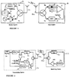
- The principle is illustrated in Figure 1. Here the transmit power of the
mobile station 2 is controlled by thebase station 4. Themobile station 2 transmits at the current power level via a combiner/splitter and antenna 2a and has anoscillator 16 and atransmit amplifier 18 . The signal is received at thebase station 4 and the power is measured (thediode 6 represents a more complex power measurement operation). The power is then compared against a threshold by a comparator 8. When the power exceeds the threshold a 'down' signal is generated. When the power is less than the threshold, an 'up' signal is generated. These are transmitted back to the mobile station via amodulator 10, via a combiner/splitter andantenna 4a, over the other half of the duplex channel and received in the mobile station which demodulates the signal in the demodulator 12 and accumulates them (+1 for an up signal. -1 for a down signal), in theaccumulator 14. The output of theaccumulator 14 controls theamplifier 18 and hence, the power directly according to a logarithmic relationship. - A vital element in the above procedure is the measurement of received signal level. The control of power can only be as accurate as this measurement. This is not a problem for existing systems in which the power control update interval corresponds to several received bits of data and in which the required bit error rate is moderately low and therefore the received signal to noise ratio is moderately high. The ability to average the received power over several bits of signal gives a significant increase in signal to noise ratio, particularly if this can be done coherently or pseudo coherently.
- However, consider the case where the bit rate is very low. In fact, consider the case where the transmitted bit rate is equal to the power control update rate and where the required error rate is moderately high. If a measurement of the received power is made in the receiving station this can only be performed on the basis of a single bit . The signal to noise ratio is perhaps as low as 0 dB on that bit so measurements will be heavily corrupted by noise.
- This situation can arise, unlike that illustrated in Figure 1, in the situation where rapid downlink power control is required so that the mobile must transmit power control signalling information to the base station. The transmission of this power control signalling information must itself be power controlled. For transmission of packet type data, it may be a requirement to permit asymmetrical traffic flow so that, on occasions, data traffic will be flowing only on the downlink. In this case the sole purpose of uplink transmissions is for power control of the downlink and these power control transmissions at the power control signalling rate must themselves be power controlled.
- The particular difficulty of this situation is the fact that, when there is no uplink data traffic on a particular link, the interference generated by any control traffic flowing on that uplink should be minimised in order to maximise the total capacity available to other links which are active on their uplinks. If power control traffic is, in fact, the only control traffic on an uplink then the transmission used to send it must be minimised, exploiting as much as possible, the very low bit rate. This can only be achieved effectively by exerting fast power control over the power control information transmission.
- In vehicular technology society 42ND VTS conference ― Frontiers of Technology Vol. 2 of 2 May 1992 pages 989 to 992 there is described a power control method in a packet switched spread spectrum communications system. In this method a received packets power is examined at a mobile unit and a power control algorithm evaluates the fading state of the channel, estimates its future state and sets the power of the control unit of the transmitter of the mobile unit for the transmission of the next packet.
- In proceedings of The National Communications Forum, Vol 41, no.11, 1987 CHICAGO, ILLINOIS, USA, pages 957 to 961 there is described automatic power control in microwave communications where controls bits are used on a return channel to either increase, decrease, or hold the power level of a forward transmitter.
- In Patent Abstracts of Japan Vol.017 no. 614 (P-1642) there is described a bit error rate detecting circuit.
- An aim of the present invention is to provide a power control apparatus for use in mobile radio systems wherein power control is exerted in a fast and efficient manner.
- According to the present invention there is provided power controller apparatus for use in mobile radio systems the apparatus comprising: a
first station 20 for transmitting data to and receiving data from a second station 22, a second station 22 for receiving data from and transmitting data to saidfirst station 20, saidfirst station 20 comprising adata source 24, means 28 for modulating the data of thedata source 24 and means 20a for transmitting data derived from saiddata source 24 and control means 30 for controlling the power of the transmitting means 20a wherein the control means 30 controls the power of the transmitting means 20a in dependence upon a comparison, characterised in that the comparison is a comparison between original data transmitted from saidfirst station 20 for reception at said second station 22 and data re-transmitted back to saidfirst station 20 from said second station 22 as back-transmitted original data. - An embodiment of the present invention will now be described with reference to Figure 2, which is a block diagram of power control apparatus.
- Referring to Figure 2, there is shown a transmitting
station 20 and a receiving station 22. The transmitting station includes adata source 24 connected to a buffer store 26, and to an input of amodulation circuit 28. The output of the buffer store 26 is connected to a first input of an exclusive OR-gate 30, which at a second input thereof, receives incoming data from the receiving station via the receiveddata circuit 32. The output of the exclusive OR-gate 30 controls a switch 34, which applies an up-step signal or a down-step signal to the input of anaccumulator 36. An output from theaccumulator 36 is connected to control a transmit amplifier 38. - The receiving station 22 includes a received
data circuit 40 which is connected to an input of amodulation circuit 42, the output of which is connected to atransmit amplifier 44. - To avoid confusion in the following discussion, the station whose transmit power is being controlled by the invention described herein is referred to as the 'transmitting station', (first station), whilst the station which is receiving the power controlled transmission and providing information relevant to the control of the transmitting station's power is referred to as the 'receiving station' (second station). This terminology does not imply that the transmitting station cannot receive, nor that the receiving station cannot transmit.
- The basic principle is to have the receiving station 22, rather than measuring the power, simply demodulate the data and communicate this data back to the transmitting
station 20, over the link operating in the other direction. It is assumed that the opposite direction link can be made more effectively (i.e. with lower errors) than the power controlled direction. - In the transmitting
station 20, the bit which was transmitted is compared against the bit reflected back from the receiving station in order to identify those bits which were received in error at the receiving station. Whenever an error is detected, the transmitted power is increased by an amount U dB. Whenever an error is not detected, the transmitted power is decreased by an amount D dB. - In the steady state the medium term average transmitted power is constant. Consider an interval of time consisting of N signalling bits. Suppose the bit error rate was B. Then the average number of up-steps over interval N is N.B and the total power rise associated with the errors was U.N.B. This must have been cancelled by an equal power reduction. The power reduction is also given by
Thus, we can control the bit error rate directly, simply by setting the ratio of U to D. - The optimum step size, U, is a function of the fading rate of the path. For slowly fading paths, U (and therefore D) should be made quite small. For rapidly fading paths, U should be made larger. The step size could be adapted according to measurements of the statistics of bit errors in the transmitting station.
- For some systems, this 'reflecting back' of data also permits a further advantage. For a low bit rate link it is usually not possible to achieve coherent demodulation because of the phase ambiguity which can arise in any decision direction derivation of a carrier reference. However, if the data is reflected back, then the transmitting end can detect a burst of errors (as opposed to erasures) at the receiving end which implies that the carrier reference has become inverted. In this case the transmitting end simply inverts its transmission in order to compensate for the receiver inversion of data 'at source'.
- The apparatus shown in Figure 2 operates as follows. The transmitting station 2a modulates the data from the
data source 24 via themodulation circuit 28 onto the transmitter at the current power level via a combiner/splitter and antenna 20a. This is received at the receiving station, modulated back onto its transmitter and sent back to the receiver in the transmitting station 22 by way of thetransmitter amplifier 44 and combiner/splitter and antenna 22a. The two directions of communications would generally be differentiated by frequency, however, because of the delay around the modulation, propagation and demodulation paths in both directions, the data source is buffered by buffer store 26 before comparison against the reflected data. The exclusive OR-gate 30 performs the comparison. If the bits are equal its output will be low (0) and theaccumulator 36 input will be fed with '- Down Step'. If the bits are different betokening an error then the output will be high (1) and the accumulator input will be fed with ' + Up Step'. The output of the accumulator controls the power of the transmitter 38 in a logarithmic fashion. - It will readily be appreciated by those skilled in the art that various modifications are possible within the scope of the present invention, as claimed.
Claims (5)
- Power controller apparatus for use in mobile radio systems the apparatus comprising:a first station (20) for transmitting data to and receiving data from a second station (22), a second station (22) for receiving data from and transmitting data to said first station (20), said first station (20) comprising a data source (24), means (28) for modulating the data of the data source (24) and means (20a) for transmitting data derived from said data source (24) and control means (30) for controlling the power of the transmitting means (20a) wherein the control means (30) controls the power of the transmitting means (20a) in dependence upon a comparison, characterised in that the comparison is a comparison between original data transmitted from said first station (20) for reception at said second station (22) and data re-transmitted back to said first station (20) from said second station (22) as back-transmitted original data.
- Apparatus as claimed in claim 1, wherein the control means (30) comprises an exclusive OR-gate (30) arranged to receive the original data from said data source (24) at a first input thereof, and at a second input thereof arranged to receive the back-transmitted original data returned from said second station (22), and in accordance with the comparison therewith, generates, an output signal for controlling switching means arranged to control an input signal to an accumulator (36) the output of which is used to control the power of the transmitting means (20a) in logarithmic fashion.
- Apparatus as claimed in claim 2, wherein when the exclusive OR-gate (30) performs the comparison, if the input bits at each of its inputs are equal, then the output will be low and the accumulator (36) will be fed with a down-step signal, and if the input bits are different, indicating an error, the output of the OR-gate (30) will be high and the accumulator (36) input will be fed with an up-step signal.
- Apparatus as claimed in any preceding claim, wherein the second station (22) includes means (40) for receiving data, means (42) for modulating the data, and means (22a) for transmitting the data back to the first station.
- Apparatus as claimed in any preceding claim, wherein said first station (20) is arranged to detect a burst of errors in data reflected back from said second station (22) indicating that a carrier reference has become inverted, and said first station (20) includes means arranged to invert data if it is transmitting to compensate for the burst of errors.
Applications Claiming Priority (2)
| Application Number | Priority Date | Filing Date | Title |
|---|---|---|---|
| GB9416202A GB2292289B (en) | 1994-08-11 | 1994-08-11 | Power control apparatus for use in mobile radio stations |
| GB9416202 | 1994-08-11 |
Publications (2)
| Publication Number | Publication Date |
|---|---|
| EP0696857A1 EP0696857A1 (en) | 1996-02-14 |
| EP0696857B1 true EP0696857B1 (en) | 2002-08-14 |
Family
ID=10759708
Family Applications (1)
| Application Number | Title | Priority Date | Filing Date |
|---|---|---|---|
| EP95109874A Expired - Lifetime EP0696857B1 (en) | 1994-08-11 | 1995-06-24 | Power control apparatus for use in mobile radio systems |
Country Status (6)
| Country | Link |
|---|---|
| US (1) | US5713074A (en) |
| EP (1) | EP0696857B1 (en) |
| JP (1) | JPH0870275A (en) |
| DE (1) | DE69527753T2 (en) |
| FI (1) | FI953800A (en) |
| GB (1) | GB2292289B (en) |
Cited By (2)
| Publication number | Priority date | Publication date | Assignee | Title |
|---|---|---|---|---|
| US7831272B2 (en) | 1995-03-31 | 2010-11-09 | Qualcomm Incorporated | Method and apparatus for performing fast power control in a mobile communication system |
| US7986749B2 (en) | 1995-03-31 | 2011-07-26 | Qualcomm Incorporated | Method and apparatus for performing fast power control in a mobile communication system |
Families Citing this family (28)
| Publication number | Priority date | Publication date | Assignee | Title |
|---|---|---|---|---|
| FI100072B (en) * | 1996-01-19 | 1997-09-15 | Nokia Mobile Phones Ltd | Method for adjusting transmission power and radio system |
| JP3818702B2 (en) * | 1996-08-07 | 2006-09-06 | 松下電器産業株式会社 | CDMA radio transmission system, transmission power control apparatus and transmission power control measuring apparatus used in the system |
| JP2861970B2 (en) * | 1996-10-23 | 1999-02-24 | 日本電気株式会社 | Communications system |
| KR100267343B1 (en) * | 1996-10-29 | 2000-10-16 | 윤종용 | External interference cancellation apparatus and method for cdma terminal |
| CN1242633C (en) * | 1996-11-27 | 2006-02-15 | 株式会社日立制作所 | Transmitting power controlling method, mobile terminal and base table |
| JPH10173594A (en) * | 1996-12-06 | 1998-06-26 | Hitachi Ltd | Code division multiple access communication system and sending power control method |
| US6259927B1 (en) * | 1997-06-06 | 2001-07-10 | Telefonaktiebolaget Lm Ericsson | Transmit power control in a radio communication system |
| US6173162B1 (en) * | 1997-06-16 | 2001-01-09 | Telefonaktiebolaget Lm Ericsson (Publ) | Multiple code channel power control in a radio communication system |
| GB9800440D0 (en) * | 1998-01-10 | 1998-03-04 | Wood John | Digital reflection internet |
| AU6057999A (en) * | 1998-09-21 | 2000-04-10 | Nokia Mobile Phones Limited | Apparatus, and associated method, for effectuating power control of a communication device |
| GB9821089D0 (en) * | 1998-09-30 | 1998-11-18 | Koninkl Philips Electronics Nv | Method for the communication of information and apparatus employing the method |
| FR2784529B1 (en) * | 1998-10-09 | 2000-12-29 | Sagem | METHOD FOR COMMISSIONING A DIGITAL DATA LINK BORROWING A TRANSMISSION MEDIUM SUBJECT TO DISTURBANCES |
| US6449463B1 (en) * | 1998-10-29 | 2002-09-10 | Qualcomm, Incorporated | Variable loop gain in double loop power control systems |
| CN1199368C (en) * | 1999-01-16 | 2005-04-27 | 皇家菲利浦电子有限公司 | Radio communication system |
| KR100651457B1 (en) * | 1999-02-13 | 2006-11-28 | 삼성전자주식회사 | Method of contiguous outer loop power control in dtx mode of cdma mobile communication system |
| US6317435B1 (en) * | 1999-03-08 | 2001-11-13 | Qualcomm Incorporated | Method and apparatus for maximizing the use of available capacity in a communication system |
| JP2000349704A (en) * | 1999-06-03 | 2000-12-15 | Matsushita Electric Ind Co Ltd | Radio communication unit, transmission power control method for radio communication unit and recording medium |
| US6782277B1 (en) * | 1999-09-30 | 2004-08-24 | Qualcomm Incorporated | Wireless communication system with base station beam sweeping |
| US6967998B1 (en) | 1999-11-12 | 2005-11-22 | Qualcomm Incorporated | Method and apparatus for monitoring transmission quality |
| EP1124340B1 (en) * | 2000-02-08 | 2003-12-03 | Alcatel | A method for setting a transmission quality target value for power control in a mobile radiocommunication system |
| JP2001345755A (en) * | 2000-05-31 | 2001-12-14 | Toshiba Corp | Radio communication system and radio device |
| US8199696B2 (en) | 2001-03-29 | 2012-06-12 | Qualcomm Incorporated | Method and apparatus for power control in a wireless communication system |
| GB2376606B (en) * | 2001-06-15 | 2003-08-06 | Motorola Inc | A method for reducing interference to communications in time division duplexing (TDD) mode between a TDD mobile and a TDD base station |
| US6665283B2 (en) * | 2001-08-10 | 2003-12-16 | Motorola, Inc. | Method and apparatus for transmitting data in a packet data communication system |
| US7328049B2 (en) * | 2002-06-28 | 2008-02-05 | Nokia Corporation | Pre-resource checking before file download |
| US20060182030A1 (en) * | 2003-05-05 | 2006-08-17 | Harris John M | Method and apparatus for transmitting data in a packet data communication |
| US7643843B2 (en) * | 2005-06-14 | 2010-01-05 | Interdigital Technology Corporation | Method and system for transmit power control in a multiple-input multiple-output wireless communication system |
| EP2481245A1 (en) * | 2009-09-24 | 2012-08-01 | Nokia Siemens Networks OY | Method for dynamically controlling an uplink transmission power of a user equipment |
Family Cites Families (8)
| Publication number | Priority date | Publication date | Assignee | Title |
|---|---|---|---|---|
| US4228538A (en) * | 1977-12-15 | 1980-10-14 | Harris Corporation | Real-time adaptive power control in satellite communications systems |
| US4495648A (en) * | 1982-12-27 | 1985-01-22 | At&T Bell Laboratories | Transmitter power control circuit |
| FI86352C (en) * | 1989-11-14 | 1992-08-10 | Nokia Oy Ab | DIGITALISKT RADIOLAENKSYSTEM OCH FOERFARANDE FOER REGLERING AV EN SAENDINGSEFFEKT I ETT DIGITALISKT RADIOLAENKSYSTEM. |
| JP2887987B2 (en) * | 1991-10-23 | 1999-05-10 | 日本電気株式会社 | Digital modulation circuit |
| JPH05189329A (en) * | 1992-01-13 | 1993-07-30 | Nec Corp | Bit error rate detecting circuit |
| CA2088753C (en) * | 1992-02-04 | 1999-02-16 | Tomoki Osawa | Point-to-multipoint communication network capable of retransmitting a multicast signal |
| GB2268365B (en) * | 1992-06-26 | 1996-01-17 | Roke Manor Research | Improvements in or relating to cellular mobile radio systems |
| JPH06132941A (en) * | 1992-10-21 | 1994-05-13 | Nec Corp | Data transfer system |
-
1994
- 1994-08-11 GB GB9416202A patent/GB2292289B/en not_active Expired - Fee Related
-
1995
- 1995-06-24 EP EP95109874A patent/EP0696857B1/en not_active Expired - Lifetime
- 1995-06-24 DE DE69527753T patent/DE69527753T2/en not_active Expired - Fee Related
- 1995-08-09 JP JP7203513A patent/JPH0870275A/en active Pending
- 1995-08-10 FI FI953800A patent/FI953800A/en unknown
- 1995-08-11 US US08/514,006 patent/US5713074A/en not_active Expired - Fee Related
Cited By (2)
| Publication number | Priority date | Publication date | Assignee | Title |
|---|---|---|---|---|
| US7831272B2 (en) | 1995-03-31 | 2010-11-09 | Qualcomm Incorporated | Method and apparatus for performing fast power control in a mobile communication system |
| US7986749B2 (en) | 1995-03-31 | 2011-07-26 | Qualcomm Incorporated | Method and apparatus for performing fast power control in a mobile communication system |
Also Published As
| Publication number | Publication date |
|---|---|
| GB2292289A (en) | 1996-02-14 |
| FI953800A0 (en) | 1995-08-10 |
| FI953800A (en) | 1996-02-12 |
| EP0696857A1 (en) | 1996-02-14 |
| GB2292289B (en) | 1998-06-17 |
| GB9416202D0 (en) | 1994-10-05 |
| JPH0870275A (en) | 1996-03-12 |
| DE69527753T2 (en) | 2003-03-20 |
| DE69527753D1 (en) | 2002-09-19 |
| US5713074A (en) | 1998-01-27 |
Similar Documents
| Publication | Publication Date | Title |
|---|---|---|
| EP0696857B1 (en) | Power control apparatus for use in mobile radio systems | |
| US6073025A (en) | Base station power control during a soft hand-off | |
| US5963870A (en) | Process for switching between IS-95 forward power control and fast forward power control | |
| KR100355328B1 (en) | Radio communication device and method of controlling transmission rate | |
| US6600933B1 (en) | Transmission diversity method | |
| KR100378970B1 (en) | Transmitting/receiving device and transmitting/receiving method | |
| CA2301152C (en) | Method and apparatus for predictive parameter control with loop delay | |
| US6188678B1 (en) | Method and apparatus for adaptive closed loop power control using open loop measurements | |
| US6577668B2 (en) | User equipment utilizing weighted open loop power control | |
| KR960014683B1 (en) | Method and apparatus for adjusting a power control threshold in a communication system | |
| RU2232484C2 (en) | Device and method of control over initial transmission power of forward communication channel in communication system with mobile objects | |
| JP3343908B2 (en) | Broadcast communication method and system, base station apparatus and mobile station | |
| US7953029B2 (en) | Mobile communication system with transmission control of data transmission rate request value | |
| JP2914444B2 (en) | CDMA transceiver | |
| EP1578030A2 (en) | Weighted open loop power control in a time division duplex communication system | |
| IL135783A (en) | Method for uplink power control for distributed satellite networks to compensate for rain fade | |
| EP1139685B1 (en) | Wireless communication device and transmission power control method | |
| KR20010087259A (en) | Wireless communication apparatus, mobile station, base station and transmission power control method | |
| MXPA04012325A (en) | Orthogonal code division multiple access system. | |
| EP1044516B1 (en) | Tstd transmitter for limiting transmission power of antenna and controlling method thereof for base station in mobile communication system | |
| CA2290406C (en) | Base station (apparatus and method) with directivity and transmission power control | |
| US6075815A (en) | Symbol-energy-to-noise-density estimation in a QPSK modulated communication system | |
| JP2001326591A (en) | Mobile unit in cdma mobile communication system | |
| KR19980077725A (en) | Forward Power Control Method of Mobile Communication System | |
| JP2001358637A (en) | Spread spectrum communication system having interference wave carrier detecting function |
Legal Events
| Date | Code | Title | Description |
|---|---|---|---|
| PUAI | Public reference made under article 153(3) epc to a published international application that has entered the european phase |
Free format text: ORIGINAL CODE: 0009012 |
|
| AK | Designated contracting states |
Kind code of ref document: A1 Designated state(s): DE FR NL SE |
|
| 17P | Request for examination filed |
Effective date: 19960403 |
|
| 18W | Application withdrawn |
Withdrawal date: 19990520 |
|
| D18W | Application withdrawn (deleted) | ||
| REG | Reference to a national code |
Ref country code: DE Ref legal event code: 8570 |
|
| 17Q | First examination report despatched |
Effective date: 20000731 |
|
| GRAG | Despatch of communication of intention to grant |
Free format text: ORIGINAL CODE: EPIDOS AGRA |
|
| GRAG | Despatch of communication of intention to grant |
Free format text: ORIGINAL CODE: EPIDOS AGRA |
|
| GRAH | Despatch of communication of intention to grant a patent |
Free format text: ORIGINAL CODE: EPIDOS IGRA |
|
| GRAH | Despatch of communication of intention to grant a patent |
Free format text: ORIGINAL CODE: EPIDOS IGRA |
|
| GRAA | (expected) grant |
Free format text: ORIGINAL CODE: 0009210 |
|
| AK | Designated contracting states |
Kind code of ref document: B1 Designated state(s): DE FR NL SE |
|
| REF | Corresponds to: |
Ref document number: 69527753 Country of ref document: DE Date of ref document: 20020919 |
|
| ET | Fr: translation filed | ||
| PGFP | Annual fee paid to national office [announced via postgrant information from national office to epo] |
Ref country code: SE Payment date: 20030604 Year of fee payment: 9 |
|
| PGFP | Annual fee paid to national office [announced via postgrant information from national office to epo] |
Ref country code: FR Payment date: 20030610 Year of fee payment: 9 |
|
| PLBE | No opposition filed within time limit |
Free format text: ORIGINAL CODE: 0009261 |
|
| STAA | Information on the status of an ep patent application or granted ep patent |
Free format text: STATUS: NO OPPOSITION FILED WITHIN TIME LIMIT |
|
| PGFP | Annual fee paid to national office [announced via postgrant information from national office to epo] |
Ref country code: NL Payment date: 20030630 Year of fee payment: 9 Ref country code: DE Payment date: 20030630 Year of fee payment: 9 |
|
| 26N | No opposition filed |
Effective date: 20030515 |
|
| PG25 | Lapsed in a contracting state [announced via postgrant information from national office to epo] |
Ref country code: SE Free format text: LAPSE BECAUSE OF NON-PAYMENT OF DUE FEES Effective date: 20040625 |
|
| PG25 | Lapsed in a contracting state [announced via postgrant information from national office to epo] |
Ref country code: NL Free format text: LAPSE BECAUSE OF NON-PAYMENT OF DUE FEES Effective date: 20050101 Ref country code: DE Free format text: LAPSE BECAUSE OF NON-PAYMENT OF DUE FEES Effective date: 20050101 |
|
| EUG | Se: european patent has lapsed | ||
| EUG | Se: european patent has lapsed | ||
| PG25 | Lapsed in a contracting state [announced via postgrant information from national office to epo] |
Ref country code: FR Free format text: LAPSE BECAUSE OF NON-PAYMENT OF DUE FEES Effective date: 20050228 |
|
| NLV4 | Nl: lapsed or anulled due to non-payment of the annual fee |
Effective date: 20050101 |
|
| REG | Reference to a national code |
Ref country code: FR Ref legal event code: ST |