EP0697201A1 - Thermal blanket with surgical access - Google Patents
Thermal blanket with surgical access Download PDFInfo
- Publication number
- EP0697201A1 EP0697201A1 EP95303126A EP95303126A EP0697201A1 EP 0697201 A1 EP0697201 A1 EP 0697201A1 EP 95303126 A EP95303126 A EP 95303126A EP 95303126 A EP95303126 A EP 95303126A EP 0697201 A1 EP0697201 A1 EP 0697201A1
- Authority
- EP
- European Patent Office
- Prior art keywords
- blanket
- slits
- slit
- adhesive
- pneumatic
- Prior art date
- Legal status (The legal status is an assumption and is not a legal conclusion. Google has not performed a legal analysis and makes no representation as to the accuracy of the status listed.)
- Granted
Links
- 239000000853 adhesive Substances 0.000 claims abstract description 53
- 230000001070 adhesive effect Effects 0.000 claims abstract description 53
- 229920001169 thermoplastic Polymers 0.000 claims abstract description 8
- 239000004416 thermosoftening plastic Substances 0.000 claims abstract description 8
- 238000007789 sealing Methods 0.000 claims 4
- 230000001419 dependent effect Effects 0.000 claims 1
- 230000036760 body temperature Effects 0.000 abstract description 4
- 239000002390 adhesive tape Substances 0.000 description 18
- 239000000463 material Substances 0.000 description 5
- 210000001015 abdomen Anatomy 0.000 description 4
- 238000001356 surgical procedure Methods 0.000 description 4
- 229910003460 diamond Inorganic materials 0.000 description 3
- 239000010432 diamond Substances 0.000 description 3
- 238000004519 manufacturing process Methods 0.000 description 3
- 238000010276 construction Methods 0.000 description 2
- 230000001276 controlling effect Effects 0.000 description 2
- 238000000034 method Methods 0.000 description 2
- 230000004048 modification Effects 0.000 description 2
- 238000012986 modification Methods 0.000 description 2
- 230000001105 regulatory effect Effects 0.000 description 2
- 230000003466 anti-cipated effect Effects 0.000 description 1
- 230000003749 cleanliness Effects 0.000 description 1
- 239000002783 friction material Substances 0.000 description 1
- 208000014674 injury Diseases 0.000 description 1
- 238000004900 laundering Methods 0.000 description 1
- 238000007493 shaping process Methods 0.000 description 1
- 230000035939 shock Effects 0.000 description 1
- 238000004513 sizing Methods 0.000 description 1
- 230000008733 trauma Effects 0.000 description 1
Images


Classifications
-
- A—HUMAN NECESSITIES
- A61—MEDICAL OR VETERINARY SCIENCE; HYGIENE
- A61F—FILTERS IMPLANTABLE INTO BLOOD VESSELS; PROSTHESES; DEVICES PROVIDING PATENCY TO, OR PREVENTING COLLAPSING OF, TUBULAR STRUCTURES OF THE BODY, e.g. STENTS; ORTHOPAEDIC, NURSING OR CONTRACEPTIVE DEVICES; FOMENTATION; TREATMENT OR PROTECTION OF EYES OR EARS; BANDAGES, DRESSINGS OR ABSORBENT PADS; FIRST-AID KITS
- A61F7/00—Heating or cooling appliances for medical or therapeutic treatment of the human body
- A61F7/0097—Blankets with active heating or cooling sources
-
- A—HUMAN NECESSITIES
- A61—MEDICAL OR VETERINARY SCIENCE; HYGIENE
- A61B—DIAGNOSIS; SURGERY; IDENTIFICATION
- A61B46/00—Surgical drapes
-
- A—HUMAN NECESSITIES
- A61—MEDICAL OR VETERINARY SCIENCE; HYGIENE
- A61B—DIAGNOSIS; SURGERY; IDENTIFICATION
- A61B46/00—Surgical drapes
- A61B46/20—Surgical drapes specially adapted for patients
- A61B2046/205—Adhesive drapes
-
- A—HUMAN NECESSITIES
- A61—MEDICAL OR VETERINARY SCIENCE; HYGIENE
- A61F—FILTERS IMPLANTABLE INTO BLOOD VESSELS; PROSTHESES; DEVICES PROVIDING PATENCY TO, OR PREVENTING COLLAPSING OF, TUBULAR STRUCTURES OF THE BODY, e.g. STENTS; ORTHOPAEDIC, NURSING OR CONTRACEPTIVE DEVICES; FOMENTATION; TREATMENT OR PROTECTION OF EYES OR EARS; BANDAGES, DRESSINGS OR ABSORBENT PADS; FIRST-AID KITS
- A61F7/00—Heating or cooling appliances for medical or therapeutic treatment of the human body
- A61F2007/0059—Heating or cooling appliances for medical or therapeutic treatment of the human body with an open fluid circuit
- A61F2007/006—Heating or cooling appliances for medical or therapeutic treatment of the human body with an open fluid circuit of gas
-
- A—HUMAN NECESSITIES
- A61—MEDICAL OR VETERINARY SCIENCE; HYGIENE
- A61F—FILTERS IMPLANTABLE INTO BLOOD VESSELS; PROSTHESES; DEVICES PROVIDING PATENCY TO, OR PREVENTING COLLAPSING OF, TUBULAR STRUCTURES OF THE BODY, e.g. STENTS; ORTHOPAEDIC, NURSING OR CONTRACEPTIVE DEVICES; FOMENTATION; TREATMENT OR PROTECTION OF EYES OR EARS; BANDAGES, DRESSINGS OR ABSORBENT PADS; FIRST-AID KITS
- A61F7/00—Heating or cooling appliances for medical or therapeutic treatment of the human body
- A61F7/02—Compresses or poultices for effecting heating or cooling
- A61F2007/0282—Compresses or poultices for effecting heating or cooling for particular medical treatments or effects
- A61F2007/0288—Compresses or poultices for effecting heating or cooling for particular medical treatments or effects during operations
Definitions
- the invention pertains to temperature controlled pneumatic disposable blankets to aid the control of a patient's body temperature and yet provide access through the inflated blanket for surgical purposes or the like.
- thermal blanket consists of an envelope defined by upper and lower flexible sheets which is inflated by a temperature controlled air under slightly superatmospheric pressure, and the air impinges on the patient's body through a plurality of orifices formed in the lower sheet.
- Typical thermal blankets are shown in U.S. Patents 1,777,982; 2,601,189; 4,572,188; 4,660,388; 4,777,802; 4,867,230 and 5,165,400.
- thermal blankets as identified above are capable of distributing temperature controlled air over a patient's body, the blanket covers the patient's entire body and it is not possible to simultaneously access the patient, for surgical purposes, for instance, while the blanket lays upon the patient and is providing temperature regulation.
- Difficulty is encountered in endeavoring to provide a surgical access through a pneumatic thermal blanket utilizing superatmospheric temperature controlled air in that the openings formed in the blanket necessary to provide access will permit the temperature regulated air to escape, and such access will interfere with the thermal regulation desired to be achieved by the blanket.
- Another object of the invention is to provide an inflatable disposable temperature control blanket having surgical access means defined therein wherein the size and configuration of the access opening may be selectively determined to accommodate use for the type of access required, and wherein the blanket is capable of maintaining the desired access opening configuration.
- Yet another object of the invention is to provide an inflatable disposable temperature control blanket having selectively usable surgical access openings defined therein wherein the openings are sealed with respect to the superatmospheric air within the blanket, and wherein the inflation of the blanket does not interfere with the shaping and sizing of the desired blanket access opening.
- a further object of the invention is to provide a disposable thermal control blanket utilizing superatmospheric temperature controlled air wherein the blanket includes adhesive patches which may be selectively employed to adhere the blanket to the patient's body for maintaining positioning thereon, and maintain the shape of surgical access openings defined in the blanket.
- a disposable temperature control inflatable blanket consisting of upper and lower thermoplastic flexible sheets heat sealed together at the sheet peripheries, and intermittently staked at spaced locations within the periphery to control inflation.
- the upper sheet which is the sheet disposed away from the patient, is air impervious, while the lower sheet includes a plurality of orifices through which the temperature controlled air within the blanket envelope escapes and is directed downwardly upon the patient's body for controlling the temperature of the patient.
- the blanket lower sheet is formed of a material having a greater coefficient of friction than the upper blanket to aid in maintaining the blanket upon the patient's body, and the temperature controlled air is supplied to the blanket through a fitting usually located at the foot end edge of the blanket.
- the blanket is economically manufactured and formed of thin flexible sheet material, and as the air supply fitting is preferably formed of a folded heavy duty paper material, the blanket may be concisely folded and stored prior to use, and its low cost permits the entire blanket to be disposed of after a single use, eliminating the need for expensive laundering, and as each blanket may be sterile packaged, its cleanliness prior to usage is guaranteed.
- a pneumatic disposable temperature control blanket such as shown in Patent 5,125,238 is provided with structure capable of defining an access opening within the central region of the blanket through which surgical procedures, or the like, may be accomplished. As the blanket will remain upon the patient during surgery, those portions of the blanket which have not been displaced to provide the access may continue to impinge temperature controlled air upon the patient for body temperature control purposes.
- the access opening through the blanket is provided by a plurality of perforated slits extending through the blanket upper and lower sheets.
- the perforations initially hold the shape of the blanket during shipping and handling and weaken the blanket so that the desired slits may be formed by fracturing the perforations merely by pulling the blanket envelope portions apart upon opposite sides of the slits, and in this manner the desired opening configuration may be produced.
- the slits include an elongated primary linear central slit located within the blanket central region intermediate the blanket lateral sides, and substantially parallel thereto.
- the central slit may extend approximately three-quarters the length of the blanket.
- the central slit is intersected by several secondary transverse slits disposed at right angles to the central slit and extending therethrough.
- the secondary slits are spaced from each other along the length of the central primary slit, and the portions of the blanket between the secondary slits, in conjunction with the central slit, define flap portions whereby the flap portions may be folded back over the upper blanket sheet thereby providing access through the blanket. Normally, both opposed flap portions will be folded away from each other to define the desired access opening.
- a secondary central transverse slit intersects the primary central slit, and two secondary end transverse slits intersect the ends of the central slit wherein four major flap portions will be defined in the blanket.
- the opposite sides of each slit will be heat sealed to prevent the loss of the air within the blanket envelope and the use of three secondary transverse slits selectively permits an access opening to be located at the patient's chest region, or abdomen region, or if desired, all four major flap portions may be folded back exposing the patient's entire torso.
- Adhesive patches are located on the blanket lower sheet having shields disposed over their adhesive face whereby selective adhesive patches may be used for adhesive purposes, as desired.
- adhesive patches are preferably located adjacent the secondary slits at the central slit ends and on the opposite side thereof with respect to the central slit, whereby such adhesive patches permit adhering to the patient's skin for maintaining the blanket position on the patient.
- adhesive patches are placed on the blanket lower sheet on either side of the central slit at the central slit opposite edges whereby, upon folding of the flap portions away from each other such adhesive patches may be used to hold the flap portions in an open condition by adhering the edges of the flap portion adjacent the central slit to the blanket upper sheet. Additionally, adhesive patches are placed upon the lower sheet spaced from the central slit, and parallel thereto, so that such patches may be used to adhere the blanket to the patient when the flap portions are folded back to provide access through the blanket.
- Another feature of the invention includes the possible use of a heat seal between the upper and lower sheets parallel to the primary central slit, and spaced therefrom, whereby the outer portion of the flap portions adjacent the central slit will not be inflated to facilitate the folding back of the flap portions to provide the access opening.
- the concepts of the invention are all incorporated into a disposable, temperature control blanket capable of being concisely folded and stored, and high production manufacturing techniques permit the slits, heat seals and adhesive patches to be economically incorporated into the blanket.
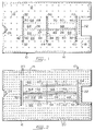
- a disposable pneumatic temperature control blanket in accord with the inventive concepts is generally indicated at 10 in the drawings.
- the blanket 10 consists of an envelope defined by an upper layer 12 of a thermoplastic air impervious flexible sheet 12 sealed to a lower thermoplastic flexible sheet 14.
- the outer surface of the sheet 14 is provided with a friction material as may be formed of a fibrous composition, and the sheets 12 and 14 are heat sealed at their periphery by the heat seal seam 16 to form an envelope.
- the sheets 12 and 14 are tacked together by heat seal welds 18 located at spaced locations to control the degree of inflation of the blanket envelope.
- a plurality of orifices 20 are defined in the lower sheet 14 and are preferably formed of a Y configuration to define valve flaps as described in U.S. Patent 5,246,656.
- the blanket includes a neck opening 22, and the temperature regulated superatmospheric pressurized air is introduced into the blanket envelope by a hose, not shown, through the inlet fitting port 24 located at the foot end of the blanket envelope.
- the blanket 10 is provided with a plurality of slits which, as later described, form the surgical access openings in the blanket to permit the blanket 10 to be used during surgery procedures, and yet provide access to the patient's body.
- the blanket 10 includes the linear slit 26 defined by a plurality of perforations which are located between the lateral edges of the sheets 12 and 14, and extends through the sheets.
- a second set of slit perforations 28 constitutes an extension of the perforations 26 and in line therewith and extending toward the neck opening 22.
- the slit perforations 26 and 28 constitute a primary slit extending substantially three-quarters of the distance between the neck opening 22 and the foot end of the blanket, and at its foot end the slit perforations 26 are intersected by the secondary slit perforations 30 which are perpendicularly related to the slit perforations 26, and extend across the perforations 26.
- the slit perforations 30 terminate at their ends 32.
- Another secondary set of slit perforations 34 are parallel to the perforations 30 and are spaced therefrom along the length of the primary slit perforations 26 - 28.
- the secondary slit perforations 34 perpendicularly intersect the perforations 26 - 28 and terminate at the ends 36.
- a third set of secondary transverse slit perforations 38 perpendicularly intersect the slit perforations 28 and are defined by the ends 40, FIG. 1.
- the upper sheet 12 and the lower sheet 14 are heat sealed in an elongated linear manner on opposite sides of the slit perforations 30 as indicated at 42, FIG. 1.
- the slit perforations 34 are heat sealed on each side by heat seals 44
- the slit perforations 38 are heat sealed on each side by the heat seals 46, FIG. 1.
- the opposite edges of the perforations 26 are heat sealed by elongated seals 47, FIG. 1, and heat seals 48 parallel to the heat seals 47 extend between the heat seals 42 and 44 preventing the air within the blanket envelope from entering that portion of the blanket envelope flap portions adjacent the slit perforations 26, as later described.
- the underside of the blanket 10 is illustrated. It is to be noted that in FIG. 2 the heat seal stakes 18 are not illustrated for purpose of simplifying the drawing, but the stakes 18 are normally visible from the blanket underside.
- An elongated adhesive tape or patch 52 is located adjacent the slit perforations 30 parallel thereto and located on the side opposite the slit perforations 30 with respect to the slit perforations 26.
- the length of the adhesive patch 52 is substantially equal to the length of the slit perforations 30, while other configurations are anticipated, and the adhesive patch preferably consists of a conventional double sided adhesive faced tape wherein one side adheres to the blanket lower sheet 14, while the exposed outer adhesive face will normally be covered by a shield of release paper or the like, which is peeled off and removed from the adhesive material when it is desired to use the adhesive characteristics of the patch 52.
- Such double sided adhesive tape is well known, as is the use of the removable shield to selectively expose the adhesive material.
- a similar adhesive patch 54 is located at the head end of the blanket 10 adjacent the slit perforations 38 as will be appreciated from FIG. 2. Additionally, elongated adhesive tapes or patches 56 are located on the opposite edges of the slit perforations 26 extending between the slit perforations 30 and 34, and in a similar manner, adhesive tape patches 58 are located upon opposite sides of the slit perforations 28 extending between the slit perforations 34 and 38.
- adhesive tapes 60 are mounted upon the lower sheet 14 parallel to the tapes 56 and in opposed relation to heat seals 48, and spaced from the slit perforations 26 about five inches.
- the adhesive tapes 62 are located parallel to and spaced from the slit perforations 28 between the slit perforations 34 and 38 in opposed relation to the heat seals 50, and are in alignment with the tape perforations 60, as will be appreciated in FIG. 2.
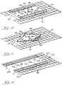
- the primary slit perforations 26 and 28 and secondary slit perforations 30, 34 and 38 define eight flap portions which, as later described, provide the access through the blanket 10.
- the two flap portions 64 are defined by the slit perforations 26, and the secondary slit perforations 30 and 34, and the heat seals 48 and the adhesive tapes 60, at the lower region of the blanket 10.
- the portions 66 define a second set of flap portions which are used when it is desired to have a maximum dimension access opening at the blanket lower region, and the flap portions 66 are defined by the heat seals 48, and slit perforations 30 and 34, and the flap portions 66 will pivot about a hinge line extending between the ends 32 and 36 of the slit portions 30 and 34, respectively.
- the flap portions 68 located adjacent the neck opening 22 are defined by the slit perforations 28, the secondary slit perforations 34 and 38, and the heat seals 50 and adhesive tapes 62.
- the flap portions 70 are defined by the heat seals 50, and the slit perforations 34 and 38, and will hinge about the hinge line defined between the slip perforation ends 36 and 40 of the slit perforations 34 and 38, respectively.
- the adjacent flap portions 64 and 66 will constitute a single major flap portion, and likewise, the adjacent flap portions 68 and 70 will define a single major flap portion, as later described.
- FIGS. 3 - 12 of the drawings Various blanket configurations capable of being defined from the previously described blanket structure will now be explained with respect to FIGS. 3 - 12 of the drawings.
- FIG. 3 illustrates the configuration of the blanket 10 when an access opening of limited length and width dimension is desired in the chest region of the patient.
- the slit perforations 28 are opened along its length and slit perforations 34 and 38 are opened from slit 28 to heat seals 50 by manually fracturing the perforations defining these slits, and once the slit perforations 28, 34 and 38 are opened to form slits, it is possible to roll back the flap portions 68 to form the rolls 72 as will be apparent from FIGS. 3 and 4.
- the adhesive tapes 58 will have their shields removed therefrom, so that the adhesive tapes or patches 58, once the rolls 72 are formed, can be made to adhere to the upper sheet 12 to maintain the configuration of the rolls 72 and provide access to the wearer's chest through access opening 74. Because of the heat seals 50, the flap portions 68 will not be inflated, and relatively tight concise rolls 72 may be formed between the secondary slits 34 and 38.
- the adhesive tapes 62 may have their shields removed therefrom wherein the adhesive faces of the tapes 62 can be used to adhere the lower portion of the roll 72 to the patient's body. Also, if desired, when placing the blanket 10 upon the patient, the adhesive tape shields located upon adhesive tapes 52 and 54 may be removed such that the adhesive faces thereof may adhere to the patient's body to position the blanket upon the body during the operation.
- temperature controlled air will be supplied to the blanket 10 through the inlet fitting 24, and temperature controlled air will impinge upon the patient through the orifices 20 at all locations except at the space 74.
- the blanket 10 may be removed from the patient and discarded, and a full blanket such as shown in Patent 5,125,238 may be placed upon the patient if continued thermal control is desired.
- the blanket configuration shown in FIGS. 5 and 6 is employed.
- the slit perforations 28 will be fully opened, as will the slit perforations 34 and 38 along their full lengths.
- This will permit the two major flap portions 68 - 70 to be folded back about the hinge lines between ends 36 and 40 to form rolls 76 of a larger dimension than rolls 72 produced with the arrangement of FIG. 3.
- the flap portions 70 will still be inflated, but the flap portions 68 are uninflated due to the heat seals 50, and the large dimension of the rolls 76 will produce a large space 78 for providing access to the wearer's chest region.
- the adhesive face shields from the tapes 58 the tapes 58 can adhere to the upper sheet 12 as shown in FIG. 6, and the large configuration of the rolls 76 maintained.
- the shields on tapes 62 will not be removed.
- FIG. 7 an arrangement similar to that shown in FIGS. 3 and 4 is illustrated except that the access 80 provided to the wearer's chest region is not defined by rolls, in that the flap portions 68 are only pulled or folded back, rather than formed into rolls 72 such as shown in FIG. 3.
- the slit perforation 28, and half of the slit perforations 34 and 38 will be opened, and the flap portions 68 are only partially folded back away from each other.
- the adhesive tapes 62 may be used to adhere the blanket to the patient, but the adhesive face shields need not be removed from the adhesive tapes 58 as conventional surgical drapes may lay on the flap portions 68 to hold the flap portions down and out of the way during the operation.
- the arrangement of FIGS. 7 and 8 provides the access opening 80, but does not require that the flap portions 68 be formed into the rolls 72 as shown in FIGS. 3 and 4.
- the blanket configuration shown in FIG. 9 is used.
- the slit perforation 26 is opened, and half of the perforations 30 and 34 are opened wherein the flap portions 64 may be formed into rolls 82, and by removing the adhesive shields from the tapes 56 the free ends of the flap portions 66 may be made to adhere to the blanket upper sheet 12 in the manner disclosed with respect to FIGS. 3 and 4.
- the access opening produced in this embodiment is indicated at 84.
- the slit perforations 30 and 34 will be fully opened along their length and the flap portion rolls will be made in a manner similar to that of the embodiment of FIGS. 5 and 6 to achieve a larger dimension access opening at the torso lower region.
- FIG. 10 a configuration of the blanket is illustrated wherein maximum diameter rolls 76 and 86 are produced to form a maximum access opening 88 extending between the patient's chest and abdomen.
- the rolls 76 are formed in the manner described with respect to FIGS. 5 and 6, and the rolls 86 are formed in a like manner from the flap portions 64 and 66.
- FIG. 11 illustrates another embodiment wherein a diamond shaped central opening is formed through the blanket 10.
- the slit perforations 26 and 28 will be fully opened, as will the slit perforation 34.
- the flap portions 64 - 66 and 68 - 70 only adjacent the slit perforation 34 are fully rolled back, and by removing the adhesive face shields from the adhesive tapes 56 and 58, it is possible to define four conical shaped rolls 90, 92, 94 and 96 which will produce the diamond shaped access opening 98 in the central region of the blanket.
- FIG. 12 discloses a blanket modification related to, but different, than the blanket 10 described in the previous embodiments.
- the blanket 99 is, basically, similar to the blanket 10, except that the blanket head end is indicated at 100 and the inlet port 102 for supplying the temperature controlled air to the blanket is located at the blanket head end.
- 104 represents the foot end of the blanket.
- Secondary slit perforations are located in the blanket 99 at 106, 108 and 110, and the primary longitudinally extending slit perforation edge is represented at 111 in FIG. 12 in its rolled position.
- adhesive tapes will be associated therewith in a manner similar to the embodiment previously described, and upon forming large rolls of the flap portions, rolls 112, 114 and 116 may be produced.
- a large access opening 118 having an open end 120 will result, and a blanket of this type is used in those instances wherein access to the lowermost regions of the patient's body is desired, while the patient is being subjected to temperature controlled air.
- a disposable thermal blanket in accord with the inventive concepts is very versatile in its use, and yet the cost of manufacture and availability is low.
Abstract
Description
- The invention pertains to temperature controlled pneumatic disposable blankets to aid the control of a patient's body temperature and yet provide access through the inflated blanket for surgical purposes or the like.
- During surgery, and thereafter, and in a number of other medical circumstances, it is desirable to bathe the patient's body with a controlled temperature air, usually heated, to reduce the likelihood of trauma and thermal shock, and for the purpose of controlling body temperature in order to achieve the most advantageous medical conditions in a specific instance.
- A common type of thermal blanket consists of an envelope defined by upper and lower flexible sheets which is inflated by a temperature controlled air under slightly superatmospheric pressure, and the air impinges on the patient's body through a plurality of orifices formed in the lower sheet. Typical thermal blankets are shown in U.S. Patents 1,777,982; 2,601,189; 4,572,188; 4,660,388; 4,777,802; 4,867,230 and 5,165,400.
- Blankets of this type are also shown in U.S. Patents 5,125,238 and 5,256,656 in which the inventor of this application is an inventor, and such patents are assigned to the assignee of this application.
- While such thermal blankets as identified above are capable of distributing temperature controlled air over a patient's body, the blanket covers the patient's entire body and it is not possible to simultaneously access the patient, for surgical purposes, for instance, while the blanket lays upon the patient and is providing temperature regulation.
- Difficulty is encountered in endeavoring to provide a surgical access through a pneumatic thermal blanket utilizing superatmospheric temperature controlled air in that the openings formed in the blanket necessary to provide access will permit the temperature regulated air to escape, and such access will interfere with the thermal regulation desired to be achieved by the blanket.
- It is an object of the invention to provide an inflatable disposable patient temperature control blanket having structure to provide a surgical access through the blanket without negatively affecting the blanket inflation.
- Another object of the invention is to provide an inflatable disposable temperature control blanket having surgical access means defined therein wherein the size and configuration of the access opening may be selectively determined to accommodate use for the type of access required, and wherein the blanket is capable of maintaining the desired access opening configuration.
- Yet another object of the invention is to provide an inflatable disposable temperature control blanket having selectively usable surgical access openings defined therein wherein the openings are sealed with respect to the superatmospheric air within the blanket, and wherein the inflation of the blanket does not interfere with the shaping and sizing of the desired blanket access opening.
- A further object of the invention is to provide a disposable thermal control blanket utilizing superatmospheric temperature controlled air wherein the blanket includes adhesive patches which may be selectively employed to adhere the blanket to the patient's body for maintaining positioning thereon, and maintain the shape of surgical access openings defined in the blanket.
- The basic configuration and construction of a disposable pneumatic thermal control blanket for medical purposes is shown in the assignee's U.S. Patent 5,125,238. This patent discloses a disposable temperature control inflatable blanket consisting of upper and lower thermoplastic flexible sheets heat sealed together at the sheet peripheries, and intermittently staked at spaced locations within the periphery to control inflation. The upper sheet, which is the sheet disposed away from the patient, is air impervious, while the lower sheet includes a plurality of orifices through which the temperature controlled air within the blanket envelope escapes and is directed downwardly upon the patient's body for controlling the temperature of the patient. Preferably, the blanket lower sheet is formed of a material having a greater coefficient of friction than the upper blanket to aid in maintaining the blanket upon the patient's body, and the temperature controlled air is supplied to the blanket through a fitting usually located at the foot end edge of the blanket.
- Because the blanket is economically manufactured and formed of thin flexible sheet material, and as the air supply fitting is preferably formed of a folded heavy duty paper material, the blanket may be concisely folded and stored prior to use, and its low cost permits the entire blanket to be disposed of after a single use, eliminating the need for expensive laundering, and as each blanket may be sterile packaged, its cleanliness prior to usage is guaranteed. In the practice of the invention, a pneumatic disposable temperature control blanket such as shown in Patent 5,125,238 is provided with structure capable of defining an access opening within the central region of the blanket through which surgical procedures, or the like, may be accomplished. As the blanket will remain upon the patient during surgery, those portions of the blanket which have not been displaced to provide the access may continue to impinge temperature controlled air upon the patient for body temperature control purposes.
- The access opening through the blanket is provided by a plurality of perforated slits extending through the blanket upper and lower sheets. The perforations initially hold the shape of the blanket during shipping and handling and weaken the blanket so that the desired slits may be formed by fracturing the perforations merely by pulling the blanket envelope portions apart upon opposite sides of the slits, and in this manner the desired opening configuration may be produced.
- The upper and lower blanket sheets are heat sealed together on opposite sides of the slits to prevent the pressurized air within the blanket envelope from escaping. Preferably, the slits include an elongated primary linear central slit located within the blanket central region intermediate the blanket lateral sides, and substantially parallel thereto. The central slit may extend approximately three-quarters the length of the blanket. The central slit is intersected by several secondary transverse slits disposed at right angles to the central slit and extending therethrough. The secondary slits are spaced from each other along the length of the central primary slit, and the portions of the blanket between the secondary slits, in conjunction with the central slit, define flap portions whereby the flap portions may be folded back over the upper blanket sheet thereby providing access through the blanket. Normally, both opposed flap portions will be folded away from each other to define the desired access opening.
- In the preferred embodiment, a secondary central transverse slit intersects the primary central slit, and two secondary end transverse slits intersect the ends of the central slit wherein four major flap portions will be defined in the blanket. The opposite sides of each slit will be heat sealed to prevent the loss of the air within the blanket envelope and the use of three secondary transverse slits selectively permits an access opening to be located at the patient's chest region, or abdomen region, or if desired, all four major flap portions may be folded back exposing the patient's entire torso.
- Adhesive patches are located on the blanket lower sheet having shields disposed over their adhesive face whereby selective adhesive patches may be used for adhesive purposes, as desired. For instance, adhesive patches are preferably located adjacent the secondary slits at the central slit ends and on the opposite side thereof with respect to the central slit, whereby such adhesive patches permit adhering to the patient's skin for maintaining the blanket position on the patient.
- Also, adhesive patches are placed on the blanket lower sheet on either side of the central slit at the central slit opposite edges whereby, upon folding of the flap portions away from each other such adhesive patches may be used to hold the flap portions in an open condition by adhering the edges of the flap portion adjacent the central slit to the blanket upper sheet. Additionally, adhesive patches are placed upon the lower sheet spaced from the central slit, and parallel thereto, so that such patches may be used to adhere the blanket to the patient when the flap portions are folded back to provide access through the blanket.
- Another feature of the invention includes the possible use of a heat seal between the upper and lower sheets parallel to the primary central slit, and spaced therefrom, whereby the outer portion of the flap portions adjacent the central slit will not be inflated to facilitate the folding back of the flap portions to provide the access opening.
- The concepts of the invention are all incorporated into a disposable, temperature control blanket capable of being concisely folded and stored, and high production manufacturing techniques permit the slits, heat seals and adhesive patches to be economically incorporated into the blanket.
- The aforementioned objects and advantages of a disposable, temperature control blanket in accord with the inventive concepts will be appreciated from the following description and accompanying drawings wherein:
- FIG. 1
- is a top plan view of the upper sheet of a blanket in accord with the invention prior to the opening of an access opening,
- FIG. 2
- is a bottom view of the lower sheet of the blanket as shown in FIG. 1,
- FIG. 3
- is a perspective view of an inflated blanket illustrating a small access opening being defined in the blanket at the patient's chest region,
- FIG. 4
- is an elevational sectional view of the blanket as taken through Section 4 - 4 of FIG. 3,
- FIG. 5
- is a perspective view of an inflated blanket illustrating the maximum size access opening being formed at the patient's chest region,
- FIG. 6
- is an elevational sectional view as taken through Section 6 - 6 of FIG. 5,
- FIG. 7
- is a perspective view of the inflated blanket illustrating a small access opening being formed in the patient's chest region, the flap portions being folded back, but not adhered to the blanket upper sheet,
- FIG. 8
- is an elevational sectional view taken along Section 8 - 8 of FIG. 7,
- FIG. 9
- is a perspective view of an inflated blanket in accord with the invention illustrating an access opening being formed in the lower region of the blanket of a smaller dimension, the flap portions adhering to the upper sheet,
- FIG. 10
- is a perspective view of the blanket illustrating the maximum dimension access opening capable of being formed wherein the patient's entire torso is accessible,
- FIG. 11
- is a perspective view of the blanket illustrating partial folding of the flap portions to provide a diamond shaped access opening at the blanket central region, and
- FIG. 12
- is a perspective view of another embodiment of a blanket in accord with the inventive concepts wherein the central primary slit extends to the foot edge of the blanket, and the air supply port is located at the blanket head end.
- A disposable pneumatic temperature control blanket in accord with the inventive concepts is generally indicated at 10 in the drawings. The
blanket 10 consists of an envelope defined by anupper layer 12 of a thermoplastic air imperviousflexible sheet 12 sealed to a lower thermoplasticflexible sheet 14. Preferably, the outer surface of thesheet 14 is provided with a friction material as may be formed of a fibrous composition, and thesheets heat seal seam 16 to form an envelope. Within theperiphery heat seal 16, thesheets heat seal welds 18 located at spaced locations to control the degree of inflation of the blanket envelope. - A plurality of
orifices 20 are defined in thelower sheet 14 and are preferably formed of a Y configuration to define valve flaps as described in U.S. Patent 5,246,656. The blanket includes a neck opening 22, and the temperature regulated superatmospheric pressurized air is introduced into the blanket envelope by a hose, not shown, through theinlet fitting port 24 located at the foot end of the blanket envelope. - The aforedescribed disposable thermal blanket construction is identical to that disclosed in the assignee's U.S. Patent 5,125,238 and the operation and use of the blanket will be appreciated from such disclosure, and is incorporated herein by reference.
- The
blanket 10 is provided with a plurality of slits which, as later described, form the surgical access openings in the blanket to permit theblanket 10 to be used during surgery procedures, and yet provide access to the patient's body. Theblanket 10 includes thelinear slit 26 defined by a plurality of perforations which are located between the lateral edges of thesheets slit perforations 28 constitutes an extension of theperforations 26 and in line therewith and extending toward theneck opening 22. The slit perforations 26 and 28 constitute a primary slit extending substantially three-quarters of the distance between theneck opening 22 and the foot end of the blanket, and at its foot end theslit perforations 26 are intersected by thesecondary slit perforations 30 which are perpendicularly related to the slit perforations 26, and extend across theperforations 26. The slit perforations 30 terminate at their ends 32. - Another secondary set of
slit perforations 34 are parallel to theperforations 30 and are spaced therefrom along the length of the primary slit perforations 26 - 28. Thesecondary slit perforations 34 perpendicularly intersect the perforations 26 - 28 and terminate at the ends 36. - At the head end of the blanket, a third set of secondary
transverse slit perforations 38 perpendicularly intersect theslit perforations 28 and are defined by theends 40, FIG. 1. - To prevent the escape of the superatmospheric air within the blanket envelope through the slit perforations 30, the
upper sheet 12 and thelower sheet 14 are heat sealed in an elongated linear manner on opposite sides of theslit perforations 30 as indicated at 42, FIG. 1. In a like manner, theslit perforations 34 are heat sealed on each side by heat seals 44, and theslit perforations 38 are heat sealed on each side by the heat seals 46, FIG. 1. - In order to prevent the escape of air at the slit perforations 26, the opposite edges of the
perforations 26 are heat sealed byelongated seals 47, FIG. 1, andheat seals 48 parallel to the heat seals 47 extend between the heat seals 42 and 44 preventing the air within the blanket envelope from entering that portion of the blanket envelope flap portions adjacent the slit perforations 26, as later described. - In a similar manner, the heat seals 49 located
adjacent slit perforations 28 will maintain the sheets bonded together, andheat seals 50, FIG. 1, parallel toseals 49 will prevent the superatmospheric air within the blanket from entering the blanket flap portions defined by the slit perforations 28, as later described. - With reference to FIG. 2, the underside of the
blanket 10 is illustrated. It is to be noted that in FIG. 2 the heat seal stakes 18 are not illustrated for purpose of simplifying the drawing, but thestakes 18 are normally visible from the blanket underside. - An elongated adhesive tape or
patch 52 is located adjacent theslit perforations 30 parallel thereto and located on the side opposite theslit perforations 30 with respect to the slit perforations 26. In the illustrated embodiment, the length of theadhesive patch 52 is substantially equal to the length of the slit perforations 30, while other configurations are anticipated, and the adhesive patch preferably consists of a conventional double sided adhesive faced tape wherein one side adheres to the blanketlower sheet 14, while the exposed outer adhesive face will normally be covered by a shield of release paper or the like, which is peeled off and removed from the adhesive material when it is desired to use the adhesive characteristics of thepatch 52. Such double sided adhesive tape is well known, as is the use of the removable shield to selectively expose the adhesive material. - A similar adhesive patch 54 is located at the head end of the
blanket 10 adjacent theslit perforations 38 as will be appreciated from FIG. 2. Additionally, elongated adhesive tapes orpatches 56 are located on the opposite edges of theslit perforations 26 extending between theslit perforations adhesive tape patches 58 are located upon opposite sides of theslit perforations 28 extending between theslit perforations - As also visible in FIG. 2,
adhesive tapes 60 are mounted upon thelower sheet 14 parallel to thetapes 56 and in opposed relation to heatseals 48, and spaced from theslit perforations 26 about five inches. In a similar manner, theadhesive tapes 62 are located parallel to and spaced from theslit perforations 28 between theslit perforations tape perforations 60, as will be appreciated in FIG. 2. - With reference to FIGS. 1 and 2, the
primary slit perforations secondary slit perforations blanket 10. The twoflap portions 64 are defined by the slit perforations 26, and thesecondary slit perforations adhesive tapes 60, at the lower region of theblanket 10. Theportions 66 define a second set of flap portions which are used when it is desired to have a maximum dimension access opening at the blanket lower region, and theflap portions 66 are defined by the heat seals 48, and slitperforations flap portions 66 will pivot about a hinge line extending between theends slit portions - In a similar manner, the
flap portions 68 located adjacent theneck opening 22 are defined by the slit perforations 28, thesecondary slit perforations adhesive tapes 62. Theflap portions 70 are defined by the heat seals 50, and theslit perforations slit perforations - From the aforedescription, it is to be appreciated that when the maximum access opening is desired, the
adjacent flap portions adjacent flap portions - Various blanket configurations capable of being defined from the previously described blanket structure will now be explained with respect to FIGS. 3 - 12 of the drawings.
- FIG. 3 illustrates the configuration of the
blanket 10 when an access opening of limited length and width dimension is desired in the chest region of the patient. In such instance, theslit perforations 28 are opened along its length and slitperforations slit 28 to heatseals 50 by manually fracturing the perforations defining these slits, and once the slit perforations 28, 34 and 38 are opened to form slits, it is possible to roll back theflap portions 68 to form therolls 72 as will be apparent from FIGS. 3 and 4. In doing so, theadhesive tapes 58 will have their shields removed therefrom, so that the adhesive tapes orpatches 58, once therolls 72 are formed, can be made to adhere to theupper sheet 12 to maintain the configuration of therolls 72 and provide access to the wearer's chest through access opening 74. Because of the heat seals 50, theflap portions 68 will not be inflated, and relatively tightconcise rolls 72 may be formed between thesecondary slits - When forming the
small rolls 72 to define aminimum chest space 74, theadhesive tapes 62 may have their shields removed therefrom wherein the adhesive faces of thetapes 62 can be used to adhere the lower portion of theroll 72 to the patient's body. Also, if desired, when placing theblanket 10 upon the patient, the adhesive tape shields located uponadhesive tapes 52 and 54 may be removed such that the adhesive faces thereof may adhere to the patient's body to position the blanket upon the body during the operation. - During the surgical operation, temperature controlled air will be supplied to the
blanket 10 through the inlet fitting 24, and temperature controlled air will impinge upon the patient through theorifices 20 at all locations except at thespace 74. At the termination of the operation, theblanket 10 may be removed from the patient and discarded, and a full blanket such as shown in Patent 5,125,238 may be placed upon the patient if continued thermal control is desired. - If it is desired that maximum access be available to the patient's chest region, the blanket configuration shown in FIGS. 5 and 6 is employed.
- In FIGS. 5 and 6, the slit perforations 28 will be fully opened, as will the
slit perforations flap portions 70 will still be inflated, but theflap portions 68 are uninflated due to the heat seals 50, and the large dimension of therolls 76 will produce alarge space 78 for providing access to the wearer's chest region. By removing the adhesive face shields from thetapes 58, thetapes 58 can adhere to theupper sheet 12 as shown in FIG. 6, and the large configuration of therolls 76 maintained. The shields ontapes 62 will not be removed. - In FIG. 7, an arrangement similar to that shown in FIGS. 3 and 4 is illustrated except that the
access 80 provided to the wearer's chest region is not defined by rolls, in that theflap portions 68 are only pulled or folded back, rather than formed intorolls 72 such as shown in FIG. 3. Theslit perforation 28, and half of theslit perforations flap portions 68 are only partially folded back away from each other. Theadhesive tapes 62 may be used to adhere the blanket to the patient, but the adhesive face shields need not be removed from theadhesive tapes 58 as conventional surgical drapes may lay on theflap portions 68 to hold the flap portions down and out of the way during the operation. The arrangement of FIGS. 7 and 8 provides the access opening 80, but does not require that theflap portions 68 be formed into therolls 72 as shown in FIGS. 3 and 4. - If it is desired to have a smaller opening access to the patient's abdomen, the blanket configuration shown in FIG. 9 is used. In this configuration, the
slit perforation 26 is opened, and half of theperforations flap portions 64 may be formed into rolls 82, and by removing the adhesive shields from thetapes 56 the free ends of theflap portions 66 may be made to adhere to the blanketupper sheet 12 in the manner disclosed with respect to FIGS. 3 and 4. The access opening produced in this embodiment is indicated at 84. - If it is desired to have a larger opening at the patient's abdomen region, the
slit perforations - In FIG. 10, a configuration of the blanket is illustrated wherein maximum diameter rolls 76 and 86 are produced to form a maximum access opening 88 extending between the patient's chest and abdomen. In this embodiment, the
rolls 76 are formed in the manner described with respect to FIGS. 5 and 6, and therolls 86 are formed in a like manner from theflap portions - FIG. 11 illustrates another embodiment wherein a diamond shaped central opening is formed through the
blanket 10. In this embodiment, theslit perforations slit perforation 34. However, the flap portions 64 - 66 and 68 - 70 only adjacent theslit perforation 34 are fully rolled back, and by removing the adhesive face shields from theadhesive tapes - FIG. 12 discloses a blanket modification related to, but different, than the
blanket 10 described in the previous embodiments. Theblanket 99 is, basically, similar to theblanket 10, except that the blanket head end is indicated at 100 and theinlet port 102 for supplying the temperature controlled air to the blanket is located at the blanket head end. 104 represents the foot end of the blanket. - Secondary slit perforations are located in the
blanket 99 at 106, 108 and 110, and the primary longitudinally extending slit perforation edge is represented at 111 in FIG. 12 in its rolled position. In this embodiment, adhesive tapes will be associated therewith in a manner similar to the embodiment previously described, and upon forming large rolls of the flap portions, rolls 112, 114 and 116 may be produced. As the slit perforation 111 extends to thefoot end 104 of theblanket 99, alarge access opening 118 having anopen end 120 will result, and a blanket of this type is used in those instances wherein access to the lowermost regions of the patient's body is desired, while the patient is being subjected to temperature controlled air. - It is to be understood that in most uses of the blanket, the adhesive shields will be removed from the
adhesive tapes 52 and 54 to adhere the blanket to the patient's body, and as to which adhesive faces are exposed, and which flap portions are to be displaced, is at the option of the operating room personnel. A disposable thermal blanket in accord with the inventive concepts is very versatile in its use, and yet the cost of manufacture and availability is low. - It is appreciated that various modifications to the inventive concepts may be apparent to those skilled in the art without departing from the spirit and scope of the invention.
Claims (13)
- A pneumatic, disposable, temperature control blanket having a periphery defined by a head end, a foot end, and lateral sides and having a central region, the blanket being formed by an envelope defined by an upper thermoplastic flexible air impervious sheet and a lower thermoplastic flexible sheet heat sealed together at the blanket periphery, a pneumatic flow chamber defined between the upper and lower sheets, an air inlet port defined in the envelope in communication with the flow chamber for supplying pressurized air thereto, and a plurality of spaced orifices defined in the lower sheet in communication with the flow chamber to convey temperature controlled air to the patient, the improvement comprising, a plurality of elongated slits defined in the blanket envelope in the blanket central region having opposite edges and extending through the upper and lower sheets forming envelope flap portions whereby said flap portions may be folded away from each other to provide access through the envelope, and heat seals sealing said slits' opposite edges to prevent air loss at said slits.
- A pneumatic, disposable, temperature control blanket having a periphery defined by a head end, a foot end, and lateral sides and having a central region, the blanket being formed by an envelope defined by an upper thermoplastic flexible air impervious sheet and a lower thermoplastic flexible sheet heat sealed together at the blanket periphery, a pneumatic flow chamber defined between the upper and lower sheets, an air inlet port defined in the envelope in communication with the flow chamber for supplying pressurized air thereto, a plurality of spaced orifices defined in the lower sheet in communication with the flow chamber to convey temperature controlled air to the patient, the improvement comprising, an elongated central primary slit defined in the blanket envelope central region having opposite edges and extending through the upper and lower sheets, said central slit being located between the blanket lateral sides and substantially parallel thereto, first and second secondary elongated slits defined in the blanket envelope each having opposite edges and extending through the upper and lower sheets, said secondary slits transversely intersecting said central slit at spaced locations along its length and forming a flap portion in the envelope between said secondary slit portions which may be folded back to provide access through the envelope, and flexible seals sealing said slits' opposite edges to prevent air loss at said slits.
- A pneumatic, disposable, temperature control blanket according to claim 2, wherein said flexible seals sealing said slits' opposite edges comprise continuous heat seals sealing said upper and lower sheets together adjacent said slits' opposite edges.
- A pneumatic, disposable, temperature control blanket according to claim 3, said secondary slits each extending through said central slit whereby said secondary slits define flap portions on each side of said central slit which may be folded away from each other.
- A pneumatic, disposable, temperature control blanket according to claim 4, wherein a third secondary slit defined in the blanket envelope has opposite edges and extends through the upper and lower sheets transversely intersecting and extending through said central slit, said third secondary slit being spaced from said second secondary slits with respect to the length of said central slit whereby flap portions are defined in the envelope between said second and third secondary slits on opposite sides of said central slit.
- A pneumatic, disposable, temperature control blanket according to any preceding claim, wherein said slits include weak perforations initially holding said slits closed and the slits' opposite edges in contiguous relationship, said slits being opened and said slits' opposite edges being separated manually by fracturing said perforations.
- A pneumatic, disposable, temperature control blanket according to any preceding claim, wherein a plurality of exposable adhesive patches are defined on the lower flexible sheet each having an adhesive face, and a removable shield is mounted on each patch face whereby removal of the shield exposes the associated adhesive face.
- A pneumatic, disposable, temperature control blanket according to claim 7, wherein said exposable adhesive patches are located on the lower flexible sheet adjacent portions of said slits.
- A pneumatic, disposable, temperature control blanket according to claim 8, wherein said adhesive patches are of an elongated linear configuration having a length substantially equal to the adjacent slit portion.
- A pneumatic, disposable, temperature control blanket according to claim 5 or any claim dependent thereon, wherein said first and third secondary slits intersect and define the ends of said central slit, wherein an exposable adhesive patch having an adhesive face is defined upon the lower flexible sheet adjacent to said first and third secondary slits and on the opposite side thereof with respect to said central slit, and wherein a removable shield is mounted on each adhesive patch adhesive face whereby removal of the shield exposes the associated adhesive face.
- A pneumatic, disposable, temperature control blanket according to claim 10, wherein an elongated adhesive patch having an adhesive face is defined upon the lower flexible sheet adjacent said central slit upon each opposite edge thereof, and wherein a removable shield is mounted on each adhesive patch adhesive face upon said central slip opposite edges whereby removal of the shield exposes the associated adhesive face and said flap portions can adhere to the upper flexible sheet when folded away from the central slit.
- A pneumatic, disposable, temperature control blanket according to claim 11, wherein said elongated adhesive patches defined upon the lower flexible sheet upon said central slit opposite edges being linear and parallel to each other and of a length substantially equal to the spacing between adjacent secondary slits.
- A pneumatic, disposable, temperature control blanket according to claim 12, wherein an outer elongated linear adhesive patch having an adhesive face is defined upon the lower flexible sheet substantially parallel to each adhesive patch located at said central slit opposite edges and spaced therefrom extending between adjacent secondary slits, wherein a removable shield is mounted on each outer adhesive patch adhesive face whereby removal thereof exposes the associated adhesive face, said outer adhesive patch permitting said lower sheet to adhere to the patient's body upon said flap portions being folded away from said central slit, and wherein an elongated heat seal seals the upper and lower sheets together adjacent said outer adhesive patches whereby the portions of said flap portions between said central slit and said outer adhesive patches will be uninflated to facilitate folding of said flap portions.
Applications Claiming Priority (2)
| Application Number | Priority Date | Filing Date | Title |
|---|---|---|---|
| US290523 | 1994-08-15 | ||
| US08/290,523 US5443488A (en) | 1994-08-15 | 1994-08-15 | Thermal blanket with surgical access |
Publications (2)
| Publication Number | Publication Date |
|---|---|
| EP0697201A1 true EP0697201A1 (en) | 1996-02-21 |
| EP0697201B1 EP0697201B1 (en) | 1999-07-14 |
Family
ID=23116389
Family Applications (1)
| Application Number | Title | Priority Date | Filing Date |
|---|---|---|---|
| EP95303126A Expired - Lifetime EP0697201B1 (en) | 1994-08-15 | 1995-05-09 | Thermal blanket with surgical access |
Country Status (6)
| Country | Link |
|---|---|
| US (1) | US5443488A (en) |
| EP (1) | EP0697201B1 (en) |
| AU (1) | AU2006995A (en) |
| CA (1) | CA2147287C (en) |
| DE (1) | DE69510735T2 (en) |
| ES (1) | ES2138147T3 (en) |
Cited By (1)
| Publication number | Priority date | Publication date | Assignee | Title |
|---|---|---|---|---|
| EP0793434A1 (en) * | 1994-11-23 | 1997-09-10 | Mallinckrodt Medical, Inc. | Inflatable blanket having openings formed therein |
Families Citing this family (90)
| Publication number | Priority date | Publication date | Assignee | Title |
|---|---|---|---|---|
| ES2029888T3 (en) | 1987-10-05 | 1992-10-01 | Augustine Medical, Inc. | A THERMAL COVER. |
| US5405371A (en) * | 1987-10-05 | 1995-04-11 | Augustine Medical, Inc. | Thermal blanket |
| US5384924A (en) * | 1992-08-03 | 1995-01-31 | Mallinckrodt Medical, Inc. | Warming blanket having multiple inlets |
| US5350417A (en) * | 1993-05-18 | 1994-09-27 | Augustine Medical, Inc. | Convective thermal blanket |
| AU1694095A (en) * | 1994-01-26 | 1995-08-15 | Mallinckrodt Medical, Inc. | Warming blanket for pediatric use |
| US6241756B1 (en) * | 1994-06-21 | 2001-06-05 | Mallinckrodt Inc. | Upper body warming blanket |
| EP0772427B1 (en) * | 1994-07-25 | 2003-05-21 | Mallinckrodt Inc. | Inflatable blanket having air flow deflector |
| US5545194A (en) * | 1994-09-30 | 1996-08-13 | Augustine Medical, Inc. | Convertible thermal blanket |
| US5964792A (en) * | 1996-08-02 | 1999-10-12 | Augustine Medical, Inc. | Convertible thermal blanket |
| US5674269A (en) * | 1995-02-06 | 1997-10-07 | Augustine Medical, Inc. | Patient warming system with user-configurable access panel |
| US5773275A (en) * | 1995-09-21 | 1998-06-30 | Augustine Medical, Inc. | Inflatable thermal blanket with provision for being secured during use |
| US5675848A (en) * | 1995-10-18 | 1997-10-14 | Mallinckrodt Medical, Inc. | Inflatable blanket having perforations of different sizes |
| US5640727A (en) * | 1995-10-18 | 1997-06-24 | Mallinckrodt Medical, Inc. | Contoured inflatable blanket |
| US5749109A (en) * | 1995-10-18 | 1998-05-12 | Mallinckrodt Medical, Inc. | Inflatable blanket having selective air flow patterns |
| US5735890A (en) * | 1995-10-18 | 1998-04-07 | Mallinckrodt Medical, Inc. | Inflatable blanket having access slits |
| US5817146A (en) * | 1995-11-09 | 1998-10-06 | Augustine Medical, Inc. | Patient warming system with IV fluid warmer |
| US5697963A (en) * | 1995-12-20 | 1997-12-16 | Augustine Medical, Inc. | Thermal blanket for a patient sitting in a chair |
| GB2308813B (en) * | 1996-01-05 | 1999-12-29 | Boc Group Plc | Garments for controlling body temperature |
| US5843145A (en) * | 1996-01-23 | 1998-12-01 | Dura-Kold Corporation | Reusable hot/cold temperature pack |
| US5800483A (en) * | 1996-03-21 | 1998-09-01 | Microtek Medical, Inc. | System and method for sterile surgical-thermal drape with active air circulation |
| US5741220A (en) * | 1996-04-17 | 1998-04-21 | Dura-Kold Corporation | Joint brace assembly and method |
| US5785716A (en) * | 1996-05-09 | 1998-07-28 | Bayron; Harry | Temperature control pad for use during medical and surgical procedures |
| US5728145A (en) * | 1996-07-22 | 1998-03-17 | Progressive Dynamics, Inc. | Thermal blanket with central air inlet |
| SE511191C2 (en) | 1996-08-14 | 1999-08-23 | Moelnlycke Health Care Ab | Method and apparatus for conditioning a patient lying on an operating table during a surgical operation |
| FR2754167B1 (en) * | 1996-10-03 | 1999-02-26 | Fauvel Guillaume | DEVICE FOR IMPROVING CARDIOVASCULAR IMAGING |
| US5813407A (en) * | 1997-05-27 | 1998-09-29 | Busch; Michael C. | Blanket with permeable window |
| US5941907A (en) | 1997-06-02 | 1999-08-24 | Augustine Medical, Inc. | Surgical barrier device incorporating an inflatable thermal blanket with a surgical drape to provide thermal control and surgical access |
| US5817147A (en) * | 1997-06-05 | 1998-10-06 | Wolf; Suzanne M. | Hypothermic envelope and apparatus for providing cooled air thereto |
| US6176870B1 (en) | 1997-08-13 | 2001-01-23 | Augustine Medical, Inc. | Inflatable thermal blanket with surgical access for use with patients in the lithotomy position |
| US5824025A (en) * | 1997-08-20 | 1998-10-20 | Augustine Medical, Inc. | System for convective warming of a patient during cardiac surgery |
| WO1999051172A1 (en) * | 1998-04-07 | 1999-10-14 | Guillaume Fauvel | Device for improving cardiovascular imaging |
| US6375673B1 (en) * | 1998-04-23 | 2002-04-23 | The Board Of Regents Of The University Of Texas System | Heat transfer blanket for and method of controlling a patient's temperature |
| US6277144B1 (en) | 1998-10-07 | 2001-08-21 | Respiratory Support Products, Inc. | Thermal conditioning apparatus |
| US7555792B2 (en) * | 1998-11-06 | 2009-07-07 | Kci Licensing, Inc. | Patient cooling enclosure |
| US6168612B1 (en) * | 1999-03-26 | 2001-01-02 | Augustine Medical, Inc. | Inflatable thermal blanket with a multilayer sheet |
| US6171333B1 (en) * | 1999-04-29 | 2001-01-09 | Merle D. Nelson | Heating and cooling comforter |
| IL131834A0 (en) * | 1999-09-09 | 2001-03-19 | M T R E Advanced Technology Lt | Method and system for improving cardiac output of a patient |
| FR2810875B1 (en) * | 2000-06-29 | 2003-05-30 | Alain Pierre Xavier Carjuzaa | DEVICE FOR SURGICAL DRAPING AND FOR THE FIGHT AGAINST PEROPERATORY THERMOLYSIS |
| US6560797B2 (en) * | 2001-04-27 | 2003-05-13 | Thawatchai Maturaporn | Disposable blanket |
| US7828038B2 (en) | 2001-06-04 | 2010-11-09 | Evrio, Inc. | Universal lightweight portable concealment means and methods |
| US7802582B2 (en) | 2006-07-10 | 2010-09-28 | Evrio, Inc. | System for concealment and shelter with structure for rapid setup and tight skin |
| US8397738B2 (en) | 2001-06-04 | 2013-03-19 | Evrio, Inc. | Modular system for concealment and shelter |
| US7766022B2 (en) | 2005-06-16 | 2010-08-03 | Eurio, Inc. | Modular system for concealment and shelter |
| US8056572B2 (en) * | 2001-06-04 | 2011-11-15 | Evrio, Inc. | System for rapid concealment and shelter including angular frames and warfighter covers |
| WO2003009788A1 (en) * | 2001-07-25 | 2003-02-06 | Zimmer Elektromedizin Gmbh | Thermal applicator and application system |
| US6689155B2 (en) * | 2001-07-27 | 2004-02-10 | Adroit Medical Systems, Inc. | Upper body convective heat therapy device and method of making and using same |
| AU2002322734A1 (en) * | 2001-07-27 | 2003-02-17 | Adroit Medical Systems, Inc. | Convective heat therapy device |
| US7172616B2 (en) * | 2002-01-17 | 2007-02-06 | Nellcor Puritan Bennett Inc. | Inflatable blanket for use in cardiac surgery |
| US8192475B2 (en) | 2002-04-10 | 2012-06-05 | Arizant Healthcare Inc. | Warming device constructions with a poncho-type patient gown |
| EP2255759B1 (en) | 2002-04-10 | 2017-09-20 | 3M Innovative Properties Company | Patient comfort apparatus and system |
| US20050015127A1 (en) * | 2003-04-10 | 2005-01-20 | Bieberich Mark T. | Perioperative warming device |
| US7291163B2 (en) * | 2003-11-14 | 2007-11-06 | Adroit Development, Inc. | Inflatable thermal blanket having air flow channels for directing a conditioned gas |
| US6994720B2 (en) * | 2003-12-04 | 2006-02-07 | Adroit Development, Inc. | Inflatable thermal blanket with sterile access |
| US7041122B2 (en) * | 2003-12-05 | 2006-05-09 | Gaymar Industries, Inc. | Inflatable blanket with a tie |
| US8313450B2 (en) * | 2004-07-21 | 2012-11-20 | Mego Afek Ac Ltd. | Inflatable compression sleeve |
| US20060020236A1 (en) * | 2004-07-21 | 2006-01-26 | Asher Ben-Nun | Disposable compression sleeve |
| US7125417B2 (en) * | 2004-08-20 | 2006-10-24 | Hagay Mizrahi | Aromatherapy herb pack |
| US8470012B2 (en) | 2004-09-08 | 2013-06-25 | Arizant Healthcare Inc. | Inflatable convective pad for surgery |
| US7846192B2 (en) * | 2004-12-07 | 2010-12-07 | Arizant Healthcare Inc. | Warming device |
| US7226454B2 (en) * | 2004-12-07 | 2007-06-05 | Arizant Healthcare Inc. | Warming device with varied permeability |
| US7364584B2 (en) * | 2004-12-07 | 2008-04-29 | Arizant Healthcare Inc. | Warming device |
| US20060178717A1 (en) * | 2005-02-10 | 2006-08-10 | Christa Harris | Adjustable disposable surgical thermal blanket |
| US7520889B2 (en) * | 2005-02-11 | 2009-04-21 | Arizant Healthcare Inc. | Thermal blanket for warming the limbs |
| US7470280B2 (en) * | 2005-02-11 | 2008-12-30 | Arizant Healthcare Inc. | Clinical garment for comfort warming and prewarming |
| US8454672B2 (en) | 2005-02-11 | 2013-06-04 | Arizant Healthcare Inc. | Warming device for perioperative use |
| US7825356B2 (en) * | 2005-09-29 | 2010-11-02 | Augustine Biomedical And Design Llc | Heater for assisting in venous catheterization |
| US8097031B2 (en) * | 2005-10-20 | 2012-01-17 | Arizant Healthcare Inc. | Warming device with provisions for deploying elements of an upper body convective apparatus and for deploying the lower portion of the warming device |
| US7914566B2 (en) * | 2005-10-20 | 2011-03-29 | Arizant Healthcare Inc. | Multifunction warming device with provision for warming hands |
| US7766950B2 (en) * | 2006-07-21 | 2010-08-03 | North American Rescue, Llc | Hypothermia treatment sack |
| US7901443B2 (en) * | 2006-09-27 | 2011-03-08 | Nellcor Puritan Bennett Llc | Method and apparatus for inflating a warming blanket |
| US7905911B2 (en) * | 2006-09-27 | 2011-03-15 | Nellcor Puritan Bennett Llc | Method and apparatus for connecting a hose to a warming blanket |
| US7879078B2 (en) * | 2006-09-27 | 2011-02-01 | Nellcor Puritan Bennett Llc | Use of convective air warming system for patient care |
| US7862599B2 (en) * | 2007-01-23 | 2011-01-04 | Arizant Healthcare Inc. | Convective warming device with a drape |
| US8535362B2 (en) * | 2008-12-23 | 2013-09-17 | The Surgical Company Holding B.V. | Device for conveying air to a person |
| US20100198320A1 (en) | 2009-01-30 | 2010-08-05 | Smiths Medical Asd, Inc. | Lateral access blanket |
| WO2011085268A2 (en) * | 2010-01-08 | 2011-07-14 | Dynatherm Medical Inc. | Methods and apparatus for enhancing vascular access in an appendage to enhance therapeutic and interventional procedures |
| US8464374B1 (en) | 2010-11-09 | 2013-06-18 | Randall Adam Thayer | Multi-functional convertible blanket |
| US8555890B2 (en) * | 2012-02-01 | 2013-10-15 | Hug-U-Vac Surgical Positioning Systems, Inc. | Surgical positioning system |
| US10206843B2 (en) | 2012-04-23 | 2019-02-19 | Hug-U-Vac Surgical Positioning Systems, Inc. | Patient positioning system |
| WO2014047429A1 (en) * | 2012-09-21 | 2014-03-27 | 3M Innovative Properties Company | Incision protection |
| CN105007867B (en) * | 2013-03-05 | 2017-04-19 | 史密斯医疗 Asd 公司 | convertible blanket |
| US20140277307A1 (en) * | 2013-03-15 | 2014-09-18 | Adroit Medical Systems, Inc | Companion animal convective air blankets |
| WO2016105487A1 (en) | 2014-12-23 | 2016-06-30 | 3M Innovative Properties Company | Convective system with hose manifold |
| JP6339746B2 (en) * | 2014-12-23 | 2018-06-06 | スリーエム イノベイティブ プロパティズ カンパニー | Configurable convection device |
| USD791511S1 (en) * | 2015-10-02 | 2017-07-11 | Vicki Walker | Medical blanket with access flaps |
| US11234860B2 (en) | 2016-10-21 | 2022-02-01 | 3M Innovative Properties Company | Multi-sectional patient warming blanket |
| CN109922763A (en) * | 2016-10-21 | 2019-06-21 | 3M创新有限公司 | Low profile forced ventilation blanket |
| US11819304B2 (en) | 2019-09-25 | 2023-11-21 | Welmed Inc. | Surgical draping device having a thermal feature to retain normal patient body heat |
| US11766369B1 (en) | 2020-09-30 | 2023-09-26 | Douglas Dillon | Single use protective cover for patient transport device |
| US11930868B2 (en) * | 2021-09-30 | 2024-03-19 | Tara A. Zlotkin | Wearable blanket usable as a blanket, towel, wrap, and worn fashionably as a skirt |
Citations (4)
| Publication number | Priority date | Publication date | Assignee | Title |
|---|---|---|---|---|
| BE780734A (en) * | 1972-03-15 | 1972-09-15 | Ethicon Inc | OPERATING FIELD. |
| US4540412A (en) * | 1983-07-14 | 1985-09-10 | The Kendall Company | Device for moist heat therapy |
| US5246656A (en) * | 1992-07-20 | 1993-09-21 | Progressive Dynamics, Inc. | Method for forming air flow control orifice in an inflated blanket |
| US5300100A (en) * | 1990-08-22 | 1994-04-05 | Advanced Warming Systems, Inc. | Body warmer |
Family Cites Families (12)
| Publication number | Priority date | Publication date | Assignee | Title |
|---|---|---|---|---|
| US1777982A (en) * | 1928-02-20 | 1930-10-07 | Popp Karl | Hot-air mat |
| US2601189A (en) * | 1949-08-22 | 1952-06-17 | Theodore Backer | Air comforter bed covering |
| US3830676A (en) * | 1973-02-28 | 1974-08-20 | Acurex Corp | Process of making a contoured thermal device |
| US4572188A (en) * | 1984-03-05 | 1986-02-25 | Augustine Scott D | Airflow cover for controlling body temperature |
| US4660388A (en) * | 1984-05-24 | 1987-04-28 | Greene Jr George J | Cooling cover |
| US4777802A (en) * | 1987-04-23 | 1988-10-18 | Steve Feher | Blanket assembly and selectively adjustable apparatus for providing heated or cooled air thereto |
| US4867230A (en) * | 1988-04-11 | 1989-09-19 | Gene Voss | Convection blanket warmer |
| US5241951B1 (en) * | 1990-09-05 | 1999-07-06 | Breg Inc | Therapeutic nonambient temperature fluid circulation system |
| US5165400A (en) * | 1991-03-04 | 1992-11-24 | Cincinnati Sub-Zero Products, Inc. | Convective hyperthermia article |
| US5125238A (en) * | 1991-04-29 | 1992-06-30 | Progressive Dynamics, Inc. | Patient warming or cooling blanket |
| US5265599A (en) * | 1992-10-01 | 1993-11-30 | Progressive Dynamics, Inc. | Patient temperature control blanket with controlled air distribution |
| US5304213A (en) * | 1993-06-14 | 1994-04-19 | Cincinnati Sub-Zero Products, Inc. | Hyper-hypothermia blanket with filtration properties |
-
1994
- 1994-08-15 US US08/290,523 patent/US5443488A/en not_active Expired - Lifetime
-
1995
- 1995-04-19 CA CA002147287A patent/CA2147287C/en not_active Expired - Fee Related
- 1995-05-09 DE DE69510735T patent/DE69510735T2/en not_active Expired - Lifetime
- 1995-05-09 ES ES95303126T patent/ES2138147T3/en not_active Expired - Lifetime
- 1995-05-09 EP EP95303126A patent/EP0697201B1/en not_active Expired - Lifetime
- 1995-05-15 AU AU20069/95A patent/AU2006995A/en not_active Abandoned
Patent Citations (4)
| Publication number | Priority date | Publication date | Assignee | Title |
|---|---|---|---|---|
| BE780734A (en) * | 1972-03-15 | 1972-09-15 | Ethicon Inc | OPERATING FIELD. |
| US4540412A (en) * | 1983-07-14 | 1985-09-10 | The Kendall Company | Device for moist heat therapy |
| US5300100A (en) * | 1990-08-22 | 1994-04-05 | Advanced Warming Systems, Inc. | Body warmer |
| US5246656A (en) * | 1992-07-20 | 1993-09-21 | Progressive Dynamics, Inc. | Method for forming air flow control orifice in an inflated blanket |
Cited By (2)
| Publication number | Priority date | Publication date | Assignee | Title |
|---|---|---|---|---|
| EP0793434A1 (en) * | 1994-11-23 | 1997-09-10 | Mallinckrodt Medical, Inc. | Inflatable blanket having openings formed therein |
| EP0793434A4 (en) * | 1994-11-23 | 1998-01-28 | Mallinckrodt Medical Inc | Inflatable blanket having openings formed therein |
Also Published As
| Publication number | Publication date |
|---|---|
| AU2006995A (en) | 1996-02-29 |
| CA2147287A1 (en) | 1996-02-16 |
| EP0697201B1 (en) | 1999-07-14 |
| ES2138147T3 (en) | 2000-01-01 |
| DE69510735T2 (en) | 1999-11-04 |
| US5443488A (en) | 1995-08-22 |
| CA2147287C (en) | 1998-12-22 |
| DE69510735D1 (en) | 1999-08-19 |
Similar Documents
| Publication | Publication Date | Title |
|---|---|---|
| US5443488A (en) | Thermal blanket with surgical access | |
| US5792216A (en) | Methods of preventing hypothermia using an upper body warming blanket | |
| EP1003449B1 (en) | System for convective warming of a patient during cardiac surgery | |
| EP0857046B1 (en) | Inflatable blanket having access slits | |
| US5964792A (en) | Convertible thermal blanket | |
| US4867146A (en) | Eye patch | |
| US7022130B2 (en) | Upper body convective heat therapy device and method of making and using same | |
| US5545194A (en) | Convertible thermal blanket | |
| US5839133A (en) | Warming blanket having multiple inlets | |
| ES2258748T3 (en) | SURGICAL CLOTH. | |
| US5674269A (en) | Patient warming system with user-configurable access panel | |
| US20070255363A1 (en) | Warming apparatus with an inflatable cover and an inlet port plug | |
| US5728145A (en) | Thermal blanket with central air inlet | |
| US20050125047A1 (en) | Inflatable thermal blanket with sterile access | |
| US20190060107A1 (en) | Convective Swaddle Blanket | |
| US6827729B2 (en) | Convective heat therapy device | |
| EP1094945B1 (en) | Flexible sheet material and method of making same | |
| WO2023111328A1 (en) | A forced air warming device |
Legal Events
| Date | Code | Title | Description |
|---|---|---|---|
| PUAI | Public reference made under article 153(3) epc to a published international application that has entered the european phase |
Free format text: ORIGINAL CODE: 0009012 |
|
| AK | Designated contracting states |
Kind code of ref document: A1 Designated state(s): DE ES FR GB IT |
|
| 17P | Request for examination filed |
Effective date: 19960219 |
|
| 17Q | First examination report despatched |
Effective date: 19980505 |
|
| GRAG | Despatch of communication of intention to grant |
Free format text: ORIGINAL CODE: EPIDOS AGRA |
|
| GRAG | Despatch of communication of intention to grant |
Free format text: ORIGINAL CODE: EPIDOS AGRA |
|
| GRAH | Despatch of communication of intention to grant a patent |
Free format text: ORIGINAL CODE: EPIDOS IGRA |
|
| GRAH | Despatch of communication of intention to grant a patent |
Free format text: ORIGINAL CODE: EPIDOS IGRA |
|
| GRAA | (expected) grant |
Free format text: ORIGINAL CODE: 0009210 |
|
| AK | Designated contracting states |
Kind code of ref document: B1 Designated state(s): DE ES FR GB IT |
|
| REF | Corresponds to: |
Ref document number: 69510735 Country of ref document: DE Date of ref document: 19990819 |
|
| ET | Fr: translation filed | ||
| REG | Reference to a national code |
Ref country code: ES Ref legal event code: FG2A Ref document number: 2138147 Country of ref document: ES Kind code of ref document: T3 |
|
| PLBE | No opposition filed within time limit |
Free format text: ORIGINAL CODE: 0009261 |
|
| STAA | Information on the status of an ep patent application or granted ep patent |
Free format text: STATUS: NO OPPOSITION FILED WITHIN TIME LIMIT |
|
| 26N | No opposition filed | ||
| REG | Reference to a national code |
Ref country code: GB Ref legal event code: IF02 |
|
| PGFP | Annual fee paid to national office [announced via postgrant information from national office to epo] |
Ref country code: DE Payment date: 20120502 Year of fee payment: 18 |
|
| PGFP | Annual fee paid to national office [announced via postgrant information from national office to epo] |
Ref country code: GB Payment date: 20120509 Year of fee payment: 18 Ref country code: FR Payment date: 20120608 Year of fee payment: 18 |
|
| PGFP | Annual fee paid to national office [announced via postgrant information from national office to epo] |
Ref country code: IT Payment date: 20120512 Year of fee payment: 18 |
|
| PGFP | Annual fee paid to national office [announced via postgrant information from national office to epo] |
Ref country code: ES Payment date: 20120607 Year of fee payment: 18 |
|
| GBPC | Gb: european patent ceased through non-payment of renewal fee |
Effective date: 20130509 |
|
| PG25 | Lapsed in a contracting state [announced via postgrant information from national office to epo] |
Ref country code: DE Free format text: LAPSE BECAUSE OF NON-PAYMENT OF DUE FEES Effective date: 20131203 |
|
| REG | Reference to a national code |
Ref country code: DE Ref legal event code: R119 Ref document number: 69510735 Country of ref document: DE Effective date: 20131203 |
|
| PG25 | Lapsed in a contracting state [announced via postgrant information from national office to epo] |
Ref country code: IT Free format text: LAPSE BECAUSE OF NON-PAYMENT OF DUE FEES Effective date: 20130509 |
|
| REG | Reference to a national code |
Ref country code: FR Ref legal event code: ST Effective date: 20140131 |
|
| PG25 | Lapsed in a contracting state [announced via postgrant information from national office to epo] |
Ref country code: GB Free format text: LAPSE BECAUSE OF NON-PAYMENT OF DUE FEES Effective date: 20130509 |
|
| PG25 | Lapsed in a contracting state [announced via postgrant information from national office to epo] |
Ref country code: FR Free format text: LAPSE BECAUSE OF NON-PAYMENT OF DUE FEES Effective date: 20130531 |
|
| REG | Reference to a national code |
Ref country code: ES Ref legal event code: FD2A Effective date: 20140606 |
|
| PG25 | Lapsed in a contracting state [announced via postgrant information from national office to epo] |
Ref country code: ES Free format text: LAPSE BECAUSE OF NON-PAYMENT OF DUE FEES Effective date: 20130510 |