EP0697253A2 - Push button controlled multifunction shower head - Google Patents
Push button controlled multifunction shower head Download PDFInfo
- Publication number
- EP0697253A2 EP0697253A2 EP95304417A EP95304417A EP0697253A2 EP 0697253 A2 EP0697253 A2 EP 0697253A2 EP 95304417 A EP95304417 A EP 95304417A EP 95304417 A EP95304417 A EP 95304417A EP 0697253 A2 EP0697253 A2 EP 0697253A2
- Authority
- EP
- European Patent Office
- Prior art keywords
- shower head
- push button
- pawl
- ratchet wheel
- water
- Prior art date
- Legal status (The legal status is an assumption and is not a legal conclusion. Google has not performed a legal analysis and makes no representation as to the accuracy of the status listed.)
- Granted
Links
Images

Classifications
-
- B—PERFORMING OPERATIONS; TRANSPORTING
- B05—SPRAYING OR ATOMISING IN GENERAL; APPLYING FLUENT MATERIALS TO SURFACES, IN GENERAL
- B05B—SPRAYING APPARATUS; ATOMISING APPARATUS; NOZZLES
- B05B3/00—Spraying or sprinkling apparatus with moving outlet elements or moving deflecting elements
- B05B3/02—Spraying or sprinkling apparatus with moving outlet elements or moving deflecting elements with rotating elements
- B05B3/04—Spraying or sprinkling apparatus with moving outlet elements or moving deflecting elements with rotating elements driven by the liquid or other fluent material discharged, e.g. the liquid actuating a motor before passing to the outlet
-
- B—PERFORMING OPERATIONS; TRANSPORTING
- B05—SPRAYING OR ATOMISING IN GENERAL; APPLYING FLUENT MATERIALS TO SURFACES, IN GENERAL
- B05B—SPRAYING APPARATUS; ATOMISING APPARATUS; NOZZLES
- B05B1/00—Nozzles, spray heads or other outlets, with or without auxiliary devices such as valves, heating means
- B05B1/14—Nozzles, spray heads or other outlets, with or without auxiliary devices such as valves, heating means with multiple outlet openings; with strainers in or outside the outlet opening
- B05B1/16—Nozzles, spray heads or other outlets, with or without auxiliary devices such as valves, heating means with multiple outlet openings; with strainers in or outside the outlet opening having selectively- effective outlets
- B05B1/1627—Nozzles, spray heads or other outlets, with or without auxiliary devices such as valves, heating means with multiple outlet openings; with strainers in or outside the outlet opening having selectively- effective outlets with a selecting mechanism comprising a gate valve, a sliding valve or a cock
- B05B1/1636—Nozzles, spray heads or other outlets, with or without auxiliary devices such as valves, heating means with multiple outlet openings; with strainers in or outside the outlet opening having selectively- effective outlets with a selecting mechanism comprising a gate valve, a sliding valve or a cock by relative rotative movement of the valve elements
-
- B—PERFORMING OPERATIONS; TRANSPORTING
- B05—SPRAYING OR ATOMISING IN GENERAL; APPLYING FLUENT MATERIALS TO SURFACES, IN GENERAL
- B05B—SPRAYING APPARATUS; ATOMISING APPARATUS; NOZZLES
- B05B1/00—Nozzles, spray heads or other outlets, with or without auxiliary devices such as valves, heating means
- B05B1/14—Nozzles, spray heads or other outlets, with or without auxiliary devices such as valves, heating means with multiple outlet openings; with strainers in or outside the outlet opening
- B05B1/18—Roses; Shower heads
Definitions
- This invention relates to multifunction shower heads and more particularly to such shower heads wherein any one of a plurality of spray patterns may be selected in a simple and easy manner by the push of a button.
- Multifunction shower heads are able to deliver water in any of many different spray patterns, such as a fine spray, a coarse spray, or a pulsating spray. Of course, many other spray patterns may also be provided. These multifunction shower heads may be offered in both wall mounted and hand held models. Therefore, the same internal mechanism should be usable in either model.
- the conventional multifunction shower heads generally require the user to turn a selector ring or dial in order to select a desired function. Turning this ring is not too easily performed by a person having soapy hands. On the wall mounted shower heads, the person tends to look at the shower head while he turns the selector ring or dial and, therefore, may get an unexpected spray in the face as the spray pattern changes from, say a narrow and directed stream to a wide pattern spray.
- a hand held shower head is usually connected to the end of a flexible rubber hose; hence, it is generally necessary to hold the shower head in one hand and to turn a selector ring or dial with the other hand in order to select a shower spray pattern.
- an object is to provide a new and improved shower head controlled by a push button multifunction spray pattern selector.
- an object of the invention is to provide both a wall mounted and a hand held shower head using cost of the same piece parts and, in the hand held model, having multifunction spray patterns which may be selected by the thumb of the hand holding the shower head.
- an object is to provide such a shower head which is more resistant to inoperativeness through a liming of parts.
- a shower head having a push button operated pawl and ratchet wheel cam controlled spray pattern selector.
- a ratchet wheel takes one step.
- a gear associated with the ratchet wheel rotates through an arc corresponding to the step of the ratchet wheel.
- Each rotation of this gear turns a shutter plate which switches the water flow from one shower pattern to the next.
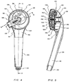
- the exterior housings 20 of the wall mounted (Fig. 1) and 22 of the hand held (Fig. 2) shower heads have a push button 24 extending therefrom.
- the wall mounted model 20 is installed by turning a coupler 28 onto an overhead plumbing pipe (not shown) projecting from the wall.
- the hand held model is connected to the plumbing via a rubber hose (not shown) attached to a coupler 30 at the end of the handle 26.
- the push button 24 may be located at any convenient position on the shower head; however, these figures show the push button in the position which is judged to be most convenient.
- the push button 24 is located so that it may be operated by the thumb of a hand holding the handle 26. This enables a person to point the shower head in any convenient direction while moving his thumb in order to change the spray pattern.
- the same face plate 32 (Fig. 2) may be used on both the wall mounted and hand held shower heads.
- One spray pattern of water emitting holes form a circular pattern of openings 34 which may issue a fine spray.
- Another circular pattern of openings 36 may issue a coarse spray.
- Grouped openings 38a-38c issue a pulsing spray.
- Any other suitable pattern of water spray holes may be provided, such as a center opening to emit a steady stream, gusher or other spray pattern of water, for example.
- the symbols at 42 are internationally adopted symbols which identify the spray pattern which has been selected.
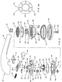
- Fig. 3 The internal parts of the shower head are shown in the exploded view of Fig. 3, and in other figures. While the parts in Fig. 3 are shown in hand held housing 22, it should be understood that they could also be in the wall mounted housing which is essentially identical to the hand held version except for the device 28 (Fig. 1) that makes a connection with the hose or plumbing pipe.
- a water passage way 46 leads from the hose coupler 30 through handle 26 to the water emitting part of the shower head.
- a recoil spring biased slide 48 is mounted inside the shower head to move back and forth (directions A,B) between normal and off normal positions.
- the slide plate is slidingly held by guide ways 50 and 51 (Fig. 4) and by cut out openings 52 and 53 (Figs. 3, 7).
- a recoil spring 54 urges the slide to a normal or an outwardly extending (direction B) position. When pushed, the push button 24 moves the slide (direction A) to an off normal or an inward position.
- An actuator pawl 56 is pivotally attached (Fig. 4) to slide 48 at a pivot point 58.
- the pawl is a molded plastic part having a leaf spring 60 integrally formed at the back in order to bias the front of the pawl into engagement against a wheel ratchet cam 62.
- slide 48 moves in direction A to the off normal position.
- Actuator pawl 56 pushes against a tooth on the ratchet wheel cam 62 to cause it to take one rotary step about an arc determined by the length of the slide 48 excursion.
- the recoil spring 54 causes the pawl 56 to return to the normal position.
- Leaf spring 60 allows the pawl 60 to pass over the apex of next to the pushed tooth and then to drop into and engage the root of the next tooth on the ratchet wheel cam 62.
- An inner housing 64 supports the parts.
- An upstanding collar 66 receives an O-ring 68 that makes a water tight seal between the inner rousing 64 and the water channel 46 in handle 26.
- the inner housing 64 has the integrally formed guides 50 and 51 and a cut out section 52 for guiding and directing slide 48 as it moves back and forth.
- An opening 72 receives a shaft 74 of a drive gear 76.
- the ratchet wheel cam 62 fits on the top of shaft 74. Each time that pawl 56 pushes against a tooth of the ratchet wheel cam 62, the drive gear 76 rotates through a particular arc corresponding to the excursion of the ratchet wheel cam.
- An O-ring 78 makes a water tight seal between the shaft 74 and the inner housing plate 64.
- a shutter plate 80 is an integral plastic part having a axle formed by a collar 82 which fits into a corresponding collar 66 of inner housing 64. Collar 66 is, in effect, a bearing for the axle 82. Shutter plate 80 has a peripheral gear 84 which meshes with the drive gear 76. Hence, the shutter plate 80 takes an incremental rotary excursion every time that the push button 24 is turned.
- the shutter plate 80 has a hole or holes 86 (Figs. 5 and 6) therein which aligns with a different channel 92, 94, 96 in diverter plate 90 (Fig. 7) on each step caused by the motion responsive to each push button operation.
- a hole or holes 86 (Figs. 5 and 6) therein which aligns with a different channel 92, 94, 96 in diverter plate 90 (Fig. 7) on each step caused by the motion responsive to each push button operation.
- water will flow along a particular diverter plate channel, and out an associated hole H1, H2, or H3, and into a selected race feeding an individually associated pattern of face plate spraying holes 34, 36, 38 (Fig. 2), thereby selecting the spray pattern of water issuing from the head.
- the shutter plate 80 may have five holes equally spaced around it periphery in order to feed water to an individually associated one of the diverter plate channels which gives a better balance of mechanical forces within the shower head.
- a second inner support plate 98 forms a means for supporting both the shutter plate 80 and the diverter plate 90.
- On the upper side of support plate 98 is an upstanding circular wall 100 which receives an O-ring 102 that seals off the water chamber.
- Support plate 98 has the cut out area 53 which is part of the guide channel in which the push button controlled slide 48 moves.
- the lower axle 106 on drive gear 76 fits through a hole 108 in the support plate 98.
- An O-ring 110 fits over axle 106 to make a water tight seal.
- Mounted on the bottom of shaft 106 is a gear 112 which moves in unison with drive gear 76 and which is coupled to turn an indicator ring 114 for displaying a symbol 42 (Fig. 2) identifying the selected spray pattern.
- a elastomeric gasket 118 has a number of holes (such as 120, 122) formed therein.
- the shutter gear 80 selects a flow channel (really five channels in the repeated patterns) on the diverter plate 90 which leads to a number of the holes 120, 122 in gasket 118. These holes are positioned over a number of races, such as 124, in a lower housing 126. Accordingly, the position of shutter plate 80 determines which of the races is energized with water and, therefore, the spray pattern of water that will issue from the shower head.
- a number of thread cutting screws (such as 128) pass through holes such as 130, 132, 134 in order to secure the assembly extending from inner housing 64 through lower housing 126.
- the individual races 124 in the lower housing 126 are positioned behind individually associated patterns of spray holes 34-40 (Fig. 2).
- the shutter plate 80 (Fig. 3) is positioned over diverter plate 90 to direct water into the first or outer most race 124, water is emitted in a fine spray through holes 34.
- the shutter plate 80 is positioned to direct water through the second or intermediate race 136, a coarse spray is emitted through a circular pattern of coarse holes 36.
- more spray patterns may be provided in the same manner.
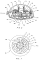
- a propeller or turbine 140 (Fig. 3A) has upstanding fins 142 which are impinged by a stream or streams of water when the shutter plate 80 diverts water into a race in which the turbine is. This impinging stream of water spins the turbine. Integrally attached to the bottom edges of fins 42, flange 144 extends around approximately three quarters of the circumference of the turbine, leaving an open space 145. At any given time one of the groups of holes 38a-38c (Fig. 2) is uncovered while the other two groups of these holes are covered.
- the face plate 150, lower housing 126, gasket 118, and diverter plate 90 are secured to the bottom of the shower head by a self tapping screw 152 driven into a boss 154 on the bottom of support plate 98.
- a plastic cap 156 snaps into a hole in the center of the face plate 150 to decorate and conceal the screw head.
Abstract
Description
- This invention relates to multifunction shower heads and more particularly to such shower heads wherein any one of a plurality of spray patterns may be selected in a simple and easy manner by the push of a button.
- Multifunction shower heads are able to deliver water in any of many different spray patterns, such as a fine spray, a coarse spray, or a pulsating spray. Of course, many other spray patterns may also be provided. These multifunction shower heads may be offered in both wall mounted and hand held models. Therefore, the same internal mechanism should be usable in either model.
- The conventional multifunction shower heads generally require the user to turn a selector ring or dial in order to select a desired function. Turning this ring is not too easily performed by a person having soapy hands. On the wall mounted shower heads, the person tends to look at the shower head while he turns the selector ring or dial and, therefore, may get an unexpected spray in the face as the spray pattern changes from, say a narrow and directed stream to a wide pattern spray. A hand held shower head is usually connected to the end of a flexible rubber hose; hence, it is generally necessary to hold the shower head in one hand and to turn a selector ring or dial with the other hand in order to select a shower spray pattern. Since the selector ring or dial is on the side of the hand held shower head which issues the water, it is necessary to either turn off the water every time that the selector ring is turned or reach around to the bottom of the shower head and turn the ring from below the head, which is very awkward.
- For these and many other reasons, it would be desirable to provide a shower head having a way to select a shower spray pattern quickly and easily without having to look at a dial. On the hand held model, it is desirable to make a selection by the thumb on the same hand that is holding the shower head, without having to either turn off the water or risk spraying in an unwanted direction.
- Accordingly, an object is to provide a new and improved shower head controlled by a push button multifunction spray pattern selector.
- In this connection, an object of the invention is to provide both a wall mounted and a hand held shower head using cost of the same piece parts and, in the hand held model, having multifunction spray patterns which may be selected by the thumb of the hand holding the shower head. Here an object is to provide such a shower head which is more resistant to inoperativeness through a liming of parts.
- In keeping with an aspect of the invention, these and other objects are accomplished by a shower head having a push button operated pawl and ratchet wheel cam controlled spray pattern selector. On each operation of the push button, a ratchet wheel takes one step. A gear associated with the ratchet wheel rotates through an arc corresponding to the step of the ratchet wheel. Each rotation of this gear turns a shutter plate which switches the water flow from one shower pattern to the next.
- A preferred embodiment of the invention is shown in the attached drawings wherein:
- Fig. 1 is a side elevation of a wall mounted model of the inventive shower head;
- Fig. 2 is a bottom plan view of a hand held model of the inventive shower head;
- Fig. 3 is an exploded view of the hand held model;
- Fig. 3A is a plan view of a propeller or turbine for giving a pulsating spray patter;
- Fig. 4 shows a portion of the hand held shower head with a number of parts removed to show the push button, pawl, and ratchet wheel construction;
- Fig. 5 is a cross section taken along line 5-5 of Fig. 4;
- Fig. 6 is a cross section taken along line 6-6 of Fig. 4; and
- Fig. 7 is a top plan view of a flow chamber.
- The
exterior housings 20 of the wall mounted (Fig. 1) and 22 of the hand held (Fig. 2) shower heads have apush button 24 extending therefrom. The wall mountedmodel 20 is installed by turning acoupler 28 onto an overhead plumbing pipe (not shown) projecting from the wall. The hand held model is connected to the plumbing via a rubber hose (not shown) attached to acoupler 30 at the end of thehandle 26. - The
push button 24 may be located at any convenient position on the shower head; however, these figures show the push button in the position which is judged to be most convenient. In the hand held model (Fig. 2), thepush button 24 is located so that it may be operated by the thumb of a hand holding thehandle 26. This enables a person to point the shower head in any convenient direction while moving his thumb in order to change the spray pattern. - The same face plate 32 (Fig. 2) may be used on both the wall mounted and hand held shower heads. One spray pattern of water emitting holes form a circular pattern of
openings 34 which may issue a fine spray. Another circular pattern ofopenings 36 may issue a coarse spray. Groupedopenings 38a-38c issue a pulsing spray. Any other suitable pattern of water spray holes may be provided, such as a center opening to emit a steady stream, gusher or other spray pattern of water, for example. The symbols at 42 are internationally adopted symbols which identify the spray pattern which has been selected. - The internal parts of the shower head are shown in the exploded view of Fig. 3, and in other figures. While the parts in Fig. 3 are shown in hand held
housing 22, it should be understood that they could also be in the wall mounted housing which is essentially identical to the hand held version except for the device 28 (Fig. 1) that makes a connection with the hose or plumbing pipe. - In Figs. 3-6, a
water passage way 46 leads from thehose coupler 30 throughhandle 26 to the water emitting part of the shower head. Inside the shower head a recoil springbiased slide 48 is mounted to move back and forth (directions A,B) between normal and off normal positions. The slide plate is slidingly held byguide ways 50 and 51 (Fig. 4) and by cut outopenings 52 and 53 (Figs. 3, 7). Arecoil spring 54 urges the slide to a normal or an outwardly extending (direction B) position. When pushed, thepush button 24 moves the slide (direction A) to an off normal or an inward position. - An
actuator pawl 56 is pivotally attached (Fig. 4) to slide 48 at apivot point 58. The pawl is a molded plastic part having aleaf spring 60 integrally formed at the back in order to bias the front of the pawl into engagement against awheel ratchet cam 62. Each time that thepush button 24 is pushed,slide 48 moves in direction A to the off normal position.Actuator pawl 56 pushes against a tooth on theratchet wheel cam 62 to cause it to take one rotary step about an arc determined by the length of theslide 48 excursion. Each time that the push button is released, therecoil spring 54 causes thepawl 56 to return to the normal position.Leaf spring 60 allows thepawl 60 to pass over the apex of next to the pushed tooth and then to drop into and engage the root of the next tooth on theratchet wheel cam 62. - An
inner housing 64 supports the parts. Anupstanding collar 66 receives an O-ring 68 that makes a water tight seal between the inner rousing 64 and thewater channel 46 inhandle 26. Theinner housing 64 has the integrally formedguides section 52 for guiding and directingslide 48 as it moves back and forth. Anopening 72 receives ashaft 74 of adrive gear 76. Theratchet wheel cam 62 fits on the top ofshaft 74. Each time thatpawl 56 pushes against a tooth of theratchet wheel cam 62, thedrive gear 76 rotates through a particular arc corresponding to the excursion of the ratchet wheel cam. An O-ring 78 makes a water tight seal between theshaft 74 and theinner housing plate 64. - A
shutter plate 80 is an integral plastic part having a axle formed by acollar 82 which fits into acorresponding collar 66 ofinner housing 64. Collar 66 is, in effect, a bearing for theaxle 82. Shutterplate 80 has aperipheral gear 84 which meshes with thedrive gear 76. Hence, theshutter plate 80 takes an incremental rotary excursion every time that thepush button 24 is turned. - The
shutter plate 80 has a hole or holes 86 (Figs. 5 and 6) therein which aligns with adifferent channel channels diverter plate 90 is selected by the stopping position of theshutter plate hole 86, water will flow along a particular diverter plate channel, and out an associated hole H1, H2, or H3, and into a selected race feeding an individually associated pattern of faceplate spraying holes diverter plate 90. Theshutter plate 80 may have five holes equally spaced around it periphery in order to feed water to an individually associated one of the diverter plate channels which gives a better balance of mechanical forces within the shower head. - A second inner support plate 98 (Fig. 3) forms a means for supporting both the
shutter plate 80 and thediverter plate 90. On the upper side ofsupport plate 98 is an upstandingcircular wall 100 which receives an O-ring 102 that seals off the water chamber.Support plate 98 has the cut outarea 53 which is part of the guide channel in which the push button controlledslide 48 moves. Thelower axle 106 ondrive gear 76 fits through ahole 108 in thesupport plate 98. An O-ring 110 fits overaxle 106 to make a water tight seal. Mounted on the bottom ofshaft 106 is a gear 112 which moves in unison withdrive gear 76 and which is coupled to turn anindicator ring 114 for displaying a symbol 42 (Fig. 2) identifying the selected spray pattern. - A
elastomeric gasket 118 has a number of holes (such as 120, 122) formed therein. Theshutter gear 80 selects a flow channel (really five channels in the repeated patterns) on thediverter plate 90 which leads to a number of theholes gasket 118. These holes are positioned over a number of races, such as 124, in alower housing 126. Accordingly, the position ofshutter plate 80 determines which of the races is energized with water and, therefore, the spray pattern of water that will issue from the shower head. - A number of thread cutting screws (such as 128) pass through holes such as 130, 132, 134 in order to secure the assembly extending from
inner housing 64 throughlower housing 126. - The
individual races 124 in thelower housing 126 are positioned behind individually associated patterns of spray holes 34-40 (Fig. 2). Thus, if the shutter plate 80 (Fig. 3) is positioned overdiverter plate 90 to direct water into the first or outermost race 124, water is emitted in a fine spray throughholes 34. If theshutter plate 80 is positioned to direct water through the second orintermediate race 136, a coarse spray is emitted through a circular pattern ofcoarse holes 36. Of course, more spray patterns may be provided in the same manner. - A propeller or turbine 140 (Fig. 3A) has
upstanding fins 142 which are impinged by a stream or streams of water when theshutter plate 80 diverts water into a race in which the turbine is. This impinging stream of water spins the turbine. Integrally attached to the bottom edges offins 42,flange 144 extends around approximately three quarters of the circumference of the turbine, leaving anopen space 145. At any given time one of the groups ofholes 38a-38c (Fig. 2) is uncovered while the other two groups of these holes are covered. - Thus, as the
turbine 140 spins, firstopen space 145 is overholes 38a (Fig. 2) and they are uncovered so that water issues therefrom. Then, holes 38a are covered byflange 144 andholes 38b are uncovered byopen space 145 so that water issues therefrom. Next, the spinning turbine uncovers holes 38c and water issues therefrom, whileflange 144 coversholes turbine 140 again uncoversholes 38a. As a result, the user feels a pulsating stream of water. - In this particular embodiment, the
face plate 150,lower housing 126,gasket 118, anddiverter plate 90, are secured to the bottom of the shower head by aself tapping screw 152 driven into aboss 154 on the bottom ofsupport plate 98. Aplastic cap 156 snaps into a hole in the center of theface plate 150 to decorate and conceal the screw head. - Those who are skilled in the art will readily perceive how to modify the invention. Therefore, the appended claims are to be construed to cover all equivalent structures which fall within the true scope and spirit of the invention.
Claims (15)
- A multifunction shower head comprising a plate having a plurality of races formed therein, each of said races having an individually associated pattern of spray holes, a spring biased push button controlled pawl and an associated ratchet wheel cam engaged by said pawl, said ratchet wheel taking one step over a predetermined arc in response to each push of said push button and its associated pawl, a shutter plate coupled to move over a predetermined arcuate distance responsive to each step of said ratchet wheel cam, and means responsive to said movement of said shutter plate for directing water into a selected one of said races.
- The shower head of claim 1 wherein said ratchet wheel cam has a plurality of teeth surrounding the circumference thereof, said pawl being pivotally attached to said push button and positioned to engage and push a tooth on said ratchet wheel cam, said pawl having a leaf spring associated therewith for pressing said pawl into engagement with said engaged tooth while allowing said pawl to deflect and ratchet over a tooth while said push button returns to a normal position after it is released from a pushed position.
- The shower head of claim 2 wherein said pawl and leaf spring are a single molded plastic piece part, a bias of said leaf spring being supplied by a memory of said plastic.
- The shower head of claim 1 wherein said shutter plate is a gear having at least one opening therein for water to flow through, and a driving gear meshing with said shutter plate gear, said driving gear and said ratchet wheel cam being mounted on a common shaft to drive said shutter plate through said arcuate distance responsive to each push button operation.
- The shower head of claim 4 wherein said shutter plate contains a plurality of holes equally distributed around a circumference thereof in order to balance mechanical forces acting in said spray head.
- The shower head of claim 1 wherein one of said races includes a pattern of grouped water emitting holes, and a water driven turbine in said one race, said turbine having a flange for sequentially covering and uncovering said groups of water emitting holes whereby a pulsating stream of water is issued from said groups of water emitting holes.
- The shower head of claim 1 and means comprising a handle extending from said spray holes to a coupler for a flexible hose leading to a source of water, said push button being in a location where it can be operated by a thumb of a hand holding said handle.
- The shower head of claim 1 wherein said shower head has a housing and means comprising a coupler on said housing for connecting said shower head to a plumbing pipe.
- A shower head comprising an outer housing having an inner housing therein, said inner housing having a guide way formed therein, a spring biased slide mounted in said guide way to move between a normal and an off-normal position, said spring bias urging said slide to said normal position, a pawl pivotally mounted on and moving with said slide toward said off-normal position, a toothed ratchet wheel mounted to be rotated over a predetermined arcuate step responsive to each off-normal movement of said pawl, a shutter means moved over a predetermined step in response to each of said arcuate steps of said ratchet wheel, and means responsive to said shutter movement for selecting one of a plurality of spray patterns.
- The shower head of claim 9 and a handle for holding said shower head, a coupler on the end of said handle for attachment to a flexible hose, and a push button for moving said slide toward said off-normal position, said push button being in a location where it may be operated by a thumb of a hand that is holding said handle.
- The shower head of claim 9 and a gear coupled to rotate with said ratchet wheel, and means driven by said gear for displaying an indication of the selected shower spray pattern.
- The shower head of claim 9 and turbine means driven by water flowing through said shower head for giving a pulsing spray pattern.
- A multifunction shower head comprising means for delivering any selected one of a plurality of different water spray patterns, push button controlled pawl and ratchet wheel cam means for selecting between said plurality of spray patterns, and means for enabling said shower head to be held by a single hand, and said push button selection being made by a thumb on said single hand.
- The shower head of claim 13 and means responsive to said push button operation for displaying an indication of the selected spray pattern.
- The shower head of claim 14 wherein said indication display means is driven by a gear associated with said ratchet wheel cam means in response to said push button action.
Priority Applications (1)
| Application Number | Priority Date | Filing Date | Title |
|---|---|---|---|
| TW084109214A TW302302B (en) | 1994-06-24 | 1995-09-04 |
Applications Claiming Priority (2)
| Application Number | Priority Date | Filing Date | Title |
|---|---|---|---|
| US265424 | 1988-10-31 | ||
| US08/265,424 US5433384A (en) | 1994-06-24 | 1994-06-24 | Push button controlled multifunction shower head |
Publications (3)
| Publication Number | Publication Date |
|---|---|
| EP0697253A2 true EP0697253A2 (en) | 1996-02-21 |
| EP0697253A3 EP0697253A3 (en) | 1996-11-27 |
| EP0697253B1 EP0697253B1 (en) | 2000-09-20 |
Family
ID=23010401
Family Applications (1)
| Application Number | Title | Priority Date | Filing Date |
|---|---|---|---|
| EP95304417A Expired - Lifetime EP0697253B1 (en) | 1994-06-24 | 1995-06-23 | Push button controlled multifunction shower head |
Country Status (7)
| Country | Link |
|---|---|
| US (1) | US5433384A (en) |
| EP (1) | EP0697253B1 (en) |
| CN (1) | CN1127679A (en) |
| AT (1) | ATE196435T1 (en) |
| CA (1) | CA2132159C (en) |
| DE (1) | DE69518886T2 (en) |
| TW (1) | TW302302B (en) |
Families Citing this family (137)
| Publication number | Priority date | Publication date | Assignee | Title |
|---|---|---|---|---|
| US5862985A (en) * | 1996-08-09 | 1999-01-26 | The Rival Company | Showerhead |
| KR20010085628A (en) | 1998-08-26 | 2001-09-07 | 게리 제이. 토마스 | Multi-functional shower head |
| USD418903S (en) * | 1998-08-26 | 2000-01-11 | Teledyne Industries, Inc. | Wall-mount shower head |
| USD415247S (en) * | 1998-08-26 | 1999-10-12 | Teledyne Industries, Inc. | Shower head face plate |
| USD418902S (en) * | 1998-08-26 | 2000-01-11 | Teledyne Industries, Inc. | Hand-held shower head |
| USD422336S (en) * | 1998-08-26 | 2000-04-04 | Teledyne Industries, Inc. | Hand-held shower head with face plate |
| US6076743A (en) * | 1998-12-03 | 2000-06-20 | Tai E International Patent And Law Office | Showerhead |
| US6367710B2 (en) * | 1998-12-03 | 2002-04-09 | Chen-Yueh Fan | Showerhead |
| DE19859524B4 (en) * | 1998-12-11 | 2005-11-17 | Fraunhofer-Gesellschaft zur Förderung der angewandten Forschung e.V. | Device for switching the spray types in a shower head |
| US6607148B1 (en) | 2000-01-13 | 2003-08-19 | Kohler Co. | Shower head |
| US6290147B1 (en) | 2000-09-19 | 2001-09-18 | Moen Incorporated | Pullout faucet wand button mechanism |
| USD451172S1 (en) | 2000-12-12 | 2001-11-27 | Water Pik, Inc. | Euro standard wall-mount shower head |
| USD453370S1 (en) | 2000-12-12 | 2002-02-05 | Water Pik, Inc. | Euro large handheld shower head |
| USD452553S1 (en) | 2000-12-12 | 2001-12-25 | Water Pik, Inc. | Euro large wall-mount shower head |
| AU2002235211A1 (en) | 2000-12-12 | 2002-06-24 | Water Pik, Inc. | Shower head assembly |
| USD452897S1 (en) | 2000-12-12 | 2002-01-08 | Water Pik, Inc. | Pan head shower head |
| USD457937S1 (en) | 2000-12-12 | 2002-05-28 | Water Pik, Inc. | Classic large handheld shower head |
| USD453551S1 (en) | 2000-12-12 | 2002-02-12 | Water Pik, Inc. | Modern wall-mount shower head |
| USD451171S1 (en) | 2000-12-12 | 2001-11-27 | Water Pik, Inc. | Traditional large wall-mount shower head |
| USD451980S1 (en) | 2000-12-12 | 2001-12-11 | Water Pik, Inc. | Traditional large handheld shower head |
| USD450807S1 (en) | 2000-12-12 | 2001-11-20 | Water Pik, Inc. | Traditional standard wall-mount shower head |
| USD452725S1 (en) | 2000-12-12 | 2002-01-01 | Water Pik, Inc. | Euro standard handheld shower head |
| USD451169S1 (en) | 2000-12-12 | 2001-11-27 | Water Pik, Inc. | Traditional standard handheld shower head |
| USD450806S1 (en) | 2000-12-12 | 2001-11-20 | Water Pik, Inc. | Modern handheld shower head |
| USD451583S1 (en) | 2000-12-12 | 2001-12-04 | Water Pik, Inc. | Classic large wall-mount shower head |
| USD450805S1 (en) | 2000-12-12 | 2001-11-20 | Water Pik, Inc. | Classic standard handheld shower head |
| USD451170S1 (en) | 2000-12-12 | 2001-11-27 | Water Pik, Inc. | Classic standard wall-mount shower head |
| US6412711B1 (en) * | 2001-02-12 | 2002-07-02 | Chen-Yueh Fan | Adjustable shower head |
| US7000854B2 (en) * | 2002-11-08 | 2006-02-21 | Moen Incorporated | Pullout spray head with single-button mode selector |
| USD485887S1 (en) | 2002-12-10 | 2004-01-27 | Water Pik, Inc. | Pan head style shower head |
| US7114666B2 (en) | 2002-12-10 | 2006-10-03 | Water Pik, Inc. | Dual massage shower head |
| US6622945B1 (en) * | 2003-02-27 | 2003-09-23 | James Wu | Shower head structure |
| US7360723B2 (en) * | 2003-11-06 | 2008-04-22 | Moty Lev | Showerhead system with integrated handle |
| US20050133614A1 (en) * | 2003-12-22 | 2005-06-23 | Shin Tai Spurt Water Of The Garden Tools Co., Ltd. | Spray pattern guide structure of a sprinkler |
| EP1577016A1 (en) * | 2004-03-17 | 2005-09-21 | Fabrizio Nobili | Showerhead with continuous control of the water jets and related selector device |
| US7740186B2 (en) | 2004-09-01 | 2010-06-22 | Water Pik, Inc. | Drenching shower head |
| US7343930B2 (en) | 2004-12-03 | 2008-03-18 | Masco Corporation Of Indiana | Sprayer with non-faucet control |
| US20060180681A1 (en) * | 2005-02-02 | 2006-08-17 | Jing Mei Industrial Holdings Limited | Faucet adaptor |
| US11267003B2 (en) | 2005-05-13 | 2022-03-08 | Delta Faucet Company | Power sprayer |
| US7850098B2 (en) | 2005-05-13 | 2010-12-14 | Masco Corporation Of Indiana | Power sprayer |
| US7303151B2 (en) * | 2005-06-07 | 2007-12-04 | James Wu | Shower head assembly |
| US7818828B2 (en) * | 2005-09-13 | 2010-10-26 | Hua-Song Zhou | Multi-functional shower head |
| CN100471577C (en) * | 2006-01-17 | 2009-03-25 | 潘尧钊 | Outlet water control mechanism for shower nozzle |
| US7871020B2 (en) | 2006-01-26 | 2011-01-18 | Masco Corporation Of Indiana | Faucet spray head with volume control |
| CA2641597C (en) | 2006-02-06 | 2013-11-26 | Masco Corporation Of Indiana | Power sprayer |
| US7611070B2 (en) * | 2006-02-28 | 2009-11-03 | Paoluccio John J | Aspirating scented oxygen enriched faucet and shower head |
| US8733675B2 (en) | 2006-04-20 | 2014-05-27 | Water Pik, Inc. | Converging spray showerhead |
| CN101069877B (en) * | 2006-05-10 | 2010-05-12 | 周华松 | Shower function switching device |
| US7159797B1 (en) * | 2006-06-20 | 2007-01-09 | Control Devices, Inc. | Spray head |
| US8066203B2 (en) * | 2006-07-05 | 2011-11-29 | Zhou Huasong | Multifunction shower head |
| US7380731B1 (en) * | 2006-09-13 | 2008-06-03 | Da Yuan Sheng Industrial Co., Ltd. | Water sprayer having two water different spraying modes |
| US8152078B2 (en) | 2006-10-25 | 2012-04-10 | Masco Corporation Of Indiana | Faucet spray head |
| US7789326B2 (en) | 2006-12-29 | 2010-09-07 | Water Pik, Inc. | Handheld showerhead with mode control and method of selecting a handheld showerhead mode |
| US8020787B2 (en) | 2006-11-29 | 2011-09-20 | Water Pik, Inc. | Showerhead system |
| US8794543B2 (en) | 2006-12-28 | 2014-08-05 | Water Pik, Inc. | Low-speed pulsating showerhead |
| US8366024B2 (en) | 2006-12-28 | 2013-02-05 | Water Pik, Inc. | Low speed pulsating showerhead |
| US7770822B2 (en) | 2006-12-28 | 2010-08-10 | Water Pik, Inc. | Hand shower with an extendable handle |
| US7374112B1 (en) * | 2007-04-19 | 2008-05-20 | Moen Incorporated | Interleaved multi-function showerhead |
| US8789218B2 (en) | 2007-05-04 | 2014-07-29 | Water Pik, Inc. | Molded arm for showerheads and method of making same |
| US20090159724A1 (en) * | 2007-12-21 | 2009-06-25 | Kacik Mark S | Turbine valve |
| USD624156S1 (en) | 2008-04-30 | 2010-09-21 | Water Pik, Inc. | Pivot ball attachment |
| CA2723867C (en) * | 2008-05-20 | 2016-02-02 | Haws Corporation | Emergency eyewash unit |
| US8020786B2 (en) * | 2008-06-02 | 2011-09-20 | Lomak Industrial Co., Ltd. | Shower head |
| CA2678769C (en) | 2008-09-15 | 2014-07-29 | Water Pik, Inc. | Shower assembly with radial mode changer |
| USD616061S1 (en) | 2008-09-29 | 2010-05-18 | Water Pik, Inc. | Showerhead assembly |
| DE102009008194B4 (en) | 2009-02-02 | 2011-07-28 | Hansgrohe AG, 77761 | Sanitary shutdown or changeover valve |
| DE102009008196A1 (en) | 2009-02-02 | 2010-08-12 | Hansgrohe Ag | Shower e.g. hand shower, has stream plate, which comprises two separate controllable group of discharge openings, which exhibit actuating element that is actuated for switching openings in uniform manner |
| US8177147B2 (en) * | 2009-04-15 | 2012-05-15 | Ray Engel | Showerhead with rotatable oval spray pattern and handheld spray pattern controller |
| CN101590454B (en) * | 2009-04-30 | 2011-05-18 | 厦门松霖科技有限公司 | Handheld sprinkler with button sprayed water form switching |
| CN101940989B (en) * | 2009-07-07 | 2012-09-05 | 厦门松霖科技有限公司 | Shower head with hydraulically rotary head part |
| USD625776S1 (en) | 2009-10-05 | 2010-10-19 | Water Pik, Inc. | Showerhead |
| US8448667B2 (en) | 2009-10-19 | 2013-05-28 | Masco Corporation Of Indiana | Multi-function pull-out wand |
| US20110114754A1 (en) * | 2009-11-18 | 2011-05-19 | Huasong ZHOU | Hydropower rotating overhead shower |
| CN101745476B (en) * | 2009-12-10 | 2014-09-10 | 厦门松霖科技有限公司 | Whip switching sprinkler and switching method |
| WO2011069426A1 (en) * | 2009-12-10 | 2011-06-16 | 厦门松霖科技有限公司 | Whip switching sprinkler and switching method |
| WO2011079775A1 (en) * | 2009-12-28 | 2011-07-07 | 厦门松霖科技有限公司 | Swingable switching shower and switching method thereof |
| WO2011085634A1 (en) * | 2010-01-12 | 2011-07-21 | 厦门松霖科技有限公司 | Button-switching showerhead and switching method thereof |
| CN101844117B (en) * | 2010-01-12 | 2012-10-03 | 厦门松霖科技有限公司 | Button-switched sprinkler and switching method thereof |
| WO2011103795A1 (en) * | 2010-02-25 | 2011-09-01 | 厦门松霖科技有限公司 | Water outlet switching device and water outlet switching method |
| CN201618625U (en) * | 2010-03-02 | 2010-11-03 | 厦门松霖科技有限公司 | Water-saving shower head with button |
| US7988070B1 (en) * | 2010-03-25 | 2011-08-02 | Chih-Sheng Yang | Shower head with brush unit |
| US8430023B2 (en) * | 2010-05-04 | 2013-04-30 | India Hynes | Adjustable wine aerator |
| US8616470B2 (en) | 2010-08-25 | 2013-12-31 | Water Pik, Inc. | Mode control valve in showerhead connector |
| CN201791614U (en) * | 2010-08-27 | 2011-04-13 | 厦门松霖科技有限公司 | Press-button switching sprinkler |
| KR101053229B1 (en) * | 2010-09-01 | 2011-08-01 | 주식회사 로보터스 | Shower head making microbubble |
| CN102101077B (en) * | 2010-12-30 | 2014-02-19 | 厦门松霖科技有限公司 | Clapper switching shower |
| CN102728506B (en) * | 2011-04-01 | 2014-10-22 | 厦门松霖科技有限公司 | Automatic returning and switching device |
| US10464079B2 (en) * | 2011-11-28 | 2019-11-05 | Xiamen Solex High-Tech Industries Co., Ltd. | Concealed top cover-type shower head |
| USD678467S1 (en) | 2012-01-27 | 2013-03-19 | Water Pik, Inc. | Ring-shaped handheld showerhead |
| USD678463S1 (en) | 2012-01-27 | 2013-03-19 | Water Pik, Inc. | Ring-shaped wall mount showerhead |
| CA2898716C (en) | 2012-06-22 | 2020-02-11 | Water Pik, Inc. | Bracket for showerhead with integral flow control |
| US9795974B2 (en) | 2012-08-08 | 2017-10-24 | Xiamen Solex High-Tech Industries Co., Ltd. | Button switching shower and its switching method |
| US9687859B2 (en) * | 2012-11-16 | 2017-06-27 | Kohler Co. | Shower device |
| US9545639B2 (en) | 2013-03-15 | 2017-01-17 | Delta Faucet Company | Multi-function wand assembly |
| CN111790528B (en) | 2013-06-13 | 2022-06-24 | 洁碧有限公司 | Shower head with multiple modes |
| EP3056281B1 (en) * | 2013-10-11 | 2018-11-28 | Sinyu Technology (Fujian) Co., Ltd. | Button switching type handheld shower head |
| USD744065S1 (en) | 2014-06-13 | 2015-11-24 | Water Pik, Inc. | Handheld showerhead |
| USD744614S1 (en) | 2014-06-13 | 2015-12-01 | Water Pik, Inc. | Wall mount showerhead |
| USD744066S1 (en) | 2014-06-13 | 2015-11-24 | Water Pik, Inc. | Wall mount showerhead |
| USD745111S1 (en) | 2014-06-13 | 2015-12-08 | Water Pik, Inc. | Wall mount showerhead |
| USD744611S1 (en) | 2014-06-13 | 2015-12-01 | Water Pik, Inc. | Handheld showerhead |
| USD744064S1 (en) | 2014-06-13 | 2015-11-24 | Water Pik, Inc. | Handheld showerhead |
| USD744612S1 (en) | 2014-06-13 | 2015-12-01 | Water Pik, Inc. | Handheld showerhead |
| CN104069964B (en) * | 2014-06-27 | 2016-07-06 | 福建欣宇卫浴科技股份有限公司 | A kind of button switching structure of Portable rose |
| CN105983492B (en) * | 2015-02-04 | 2018-07-03 | 厦门松霖科技股份有限公司 | A kind of multifunctional gondola water faucet |
| CN104772235B (en) * | 2015-04-13 | 2017-09-05 | 厦门明合卫浴设备有限公司 | A kind of shower rotates water-bound |
| CN104923420B (en) * | 2015-06-26 | 2017-10-27 | 厦门英仕卫浴有限公司 | A kind of discharge switching device |
| DE102015216180A1 (en) * | 2015-08-25 | 2017-03-02 | Hansgrohe Se | Sanitary switching device and sanitary fitting |
| US9829116B2 (en) * | 2015-08-27 | 2017-11-28 | Huasong ZHOU | Switch valve and shower head applied with the switch valve |
| CN205013826U (en) * | 2015-08-31 | 2016-02-03 | 厦门建霖工业有限公司 | Multi -functional structure of individual palpation button |
| CN105478251B (en) * | 2015-10-09 | 2018-05-25 | 厦门倍杰特科技股份公司 | It presses shower head switched |
| CN105478253A (en) * | 2015-10-09 | 2016-04-13 | 厦门倍杰特科技有限公司 | Pressing rotary switching water outlet mechanism and sprinkler |
| CN105583094B (en) * | 2015-10-09 | 2018-04-17 | 厦门倍杰特科技股份公司 | Line traffic control top-spraying gondola |
| CN106622705B (en) * | 2015-11-02 | 2019-02-15 | 厦门松霖科技股份有限公司 | A kind of toggle cyclic switching sealing shower |
| US10449558B2 (en) | 2016-02-01 | 2019-10-22 | Water Pik, Inc. | Handheld pet spray wand |
| USD803981S1 (en) | 2016-02-01 | 2017-11-28 | Water Pik, Inc. | Handheld spray nozzle |
| US10265710B2 (en) | 2016-04-15 | 2019-04-23 | Water Pik, Inc. | Showerhead with dual oscillating massage |
| USD970684S1 (en) | 2016-04-15 | 2022-11-22 | Water Pik, Inc. | Showerhead |
| CN106000686B (en) * | 2016-07-15 | 2018-08-07 | 恺霖卫浴科技(厦门)有限公司 | A kind of shower facilitating switching water discharging state |
| CN106000689B (en) * | 2016-07-28 | 2018-12-25 | 厦门建霖健康家居股份有限公司 | Double-button shower and its working method |
| CN106362883B (en) * | 2016-08-30 | 2019-02-12 | 厦门建霖健康家居股份有限公司 | One kind is with the pause multi-functional module of water |
| EP3669997B1 (en) | 2016-09-08 | 2022-10-12 | Water Pik, Inc. | Pause assembly for showerheads |
| CN107159476B (en) * | 2017-07-10 | 2023-03-31 | 恺霖卫浴科技(厦门)有限公司 | Handheld shower head capable of switching water outlet state through keys |
| USD843549S1 (en) | 2017-07-19 | 2019-03-19 | Water Pik, Inc. | Handheld spray nozzle |
| CN108580069B (en) * | 2017-12-29 | 2021-09-21 | 重庆新康洁具有限责任公司 | Shower nozzle structure |
| USD872227S1 (en) | 2018-04-20 | 2020-01-07 | Water Pik, Inc. | Handheld spray device |
| CN110656681B (en) | 2018-06-28 | 2021-04-23 | 科勒公司 | Pause type hand-held shower support |
| US10722906B2 (en) * | 2018-09-19 | 2020-07-28 | Purity (Xiamen) Sanitary Ware Co., Ltd. | Push-button switching shower head structure |
| CN109746133A (en) * | 2018-12-12 | 2019-05-14 | 厦门松霖科技股份有限公司 | A kind of discharging device and the driving mechanism for discharging device |
| US10946394B2 (en) * | 2018-12-20 | 2021-03-16 | Purity (Xiamen) Sanitary Ware Co., Ltd. | Shower head water-saving switching structure and shower head |
| GB2584080B (en) * | 2019-05-13 | 2021-05-19 | Kohler Mira Ltd | Control mechanism |
| US11618043B2 (en) | 2019-08-09 | 2023-04-04 | Delta Faucet Company | Flow restricting and diverting manifold for multiple function showerhead systems |
| US11555298B2 (en) | 2020-01-17 | 2023-01-17 | Delta Faucet Company | Locking side sprayer |
| US11505926B2 (en) | 2020-01-24 | 2022-11-22 | Delta Faucet Company | Multiple function shower systems including consolidated mode switching controls |
| US11668079B2 (en) | 2020-01-24 | 2023-06-06 | Delta Faucet Company | Multiple function shower systems facilitating low actuation force mode switching |
| US11660623B2 (en) | 2020-09-03 | 2023-05-30 | Etl, Llc | Showerhead assembly with oscillating nozzle |
| US11376614B2 (en) | 2020-10-01 | 2022-07-05 | Etl, Llc | Showerhead assembly with sequentially pulsing nozzle sets |
Family Cites Families (6)
| Publication number | Priority date | Publication date | Assignee | Title |
|---|---|---|---|---|
| US3963179A (en) * | 1975-09-19 | 1976-06-15 | Continental Hair Products, Inc. | Shower head adapted to produce steady or pulsating flows |
| US4398669A (en) * | 1977-05-09 | 1983-08-16 | Teledyne Industries, Inc. | Fluid-spray discharge apparatus |
| US4165837A (en) * | 1978-03-30 | 1979-08-28 | Associated Mills, Inc. | Power controlling apparatus in a showerhead |
| US4754928A (en) * | 1987-01-14 | 1988-07-05 | Alsons Corporation | Variable massage showerhead |
| IT219634Z2 (en) * | 1990-06-06 | 1993-04-21 | Visentin Spa | SHOWER NOZZLE PROVIDED WITH SELECTION MEANS BETWEEN STRONG JET AND SOFT JET |
| US5215258A (en) * | 1991-08-06 | 1993-06-01 | Pollenex Corporation | Active shower head |
-
1994
- 1994-06-24 US US08/265,424 patent/US5433384A/en not_active Expired - Lifetime
- 1994-09-15 CA CA002132159A patent/CA2132159C/en not_active Expired - Fee Related
-
1995
- 1995-06-23 DE DE69518886T patent/DE69518886T2/en not_active Expired - Lifetime
- 1995-06-23 AT AT95304417T patent/ATE196435T1/en not_active IP Right Cessation
- 1995-06-23 EP EP95304417A patent/EP0697253B1/en not_active Expired - Lifetime
- 1995-06-24 CN CN95109140.9A patent/CN1127679A/en active Pending
- 1995-09-04 TW TW084109214A patent/TW302302B/zh active
Non-Patent Citations (1)
| Title |
|---|
| None |
Also Published As
| Publication number | Publication date |
|---|---|
| ATE196435T1 (en) | 2000-10-15 |
| EP0697253B1 (en) | 2000-09-20 |
| DE69518886T2 (en) | 2001-04-12 |
| TW302302B (en) | 1997-04-11 |
| CN1127679A (en) | 1996-07-31 |
| CA2132159A1 (en) | 1995-12-25 |
| DE69518886D1 (en) | 2000-10-26 |
| US5433384A (en) | 1995-07-18 |
| CA2132159C (en) | 2005-08-09 |
| EP0697253A3 (en) | 1996-11-27 |
Similar Documents
| Publication | Publication Date | Title |
|---|---|---|
| US5433384A (en) | Push button controlled multifunction shower head | |
| US5476225A (en) | Multi spray pattern shower head | |
| US5215258A (en) | Active shower head | |
| US6237862B1 (en) | Rotary driven sprinkler with mulitiple nozzle ring | |
| US20230381805A1 (en) | Angularly Adjusted Spray Nozzle | |
| US7111795B2 (en) | Revolving spray shower head | |
| US5499767A (en) | Shower head having elongated arm, plural nozzles, and plural inlet lines | |
| US5862985A (en) | Showerhead | |
| US6367710B2 (en) | Showerhead | |
| US6869026B2 (en) | Rotary sprinkler with arc adjustment guide and flow-through shaft | |
| JP3751676B2 (en) | Multifunction hand shower | |
| US8020786B2 (en) | Shower head | |
| GB1588616A (en) | Fluid-spray discharge-apparatus | |
| US2693390A (en) | Lawn sprinkler | |
| EP0461089A2 (en) | Shower head provided with means for adjusting the ejected water spray | |
| CN218222960U (en) | Subassembly and gondola water faucet of water function are gone out and are switched in area pause | |
| US3545681A (en) | Shower head | |
| CN217963013U (en) | Button switching shower head capable of adjusting flow | |
| HU227412B1 (en) | Shower head for a sanitary shower | |
| JPS59191845A (en) | Display device of air flow direction of air conditioner | |
| JP2001281019A (en) | Scale display device and flowmeter equipped with the same | |
| JPS60117176A (en) | Alarm clock |
Legal Events
| Date | Code | Title | Description |
|---|---|---|---|
| PUAI | Public reference made under article 153(3) epc to a published international application that has entered the european phase |
Free format text: ORIGINAL CODE: 0009012 |
|
| AK | Designated contracting states |
Kind code of ref document: A2 Designated state(s): AT BE CH DE DK ES FR GB IE IT LI NL SE |
|
| RBV | Designated contracting states (corrected) |
Designated state(s): AT BE CH DE DK ES FR GB IE IT LI NL SE |
|
| PUAL | Search report despatched |
Free format text: ORIGINAL CODE: 0009013 |
|
| 17P | Request for examination filed |
Effective date: 19960822 |
|
| AK | Designated contracting states |
Kind code of ref document: A3 Designated state(s): AT BE CH DE DK ES FR GB IE IT LI NL SE |
|
| 17Q | First examination report despatched |
Effective date: 19970731 |
|
| GRAG | Despatch of communication of intention to grant |
Free format text: ORIGINAL CODE: EPIDOS AGRA |
|
| GRAG | Despatch of communication of intention to grant |
Free format text: ORIGINAL CODE: EPIDOS AGRA |
|
| GRAH | Despatch of communication of intention to grant a patent |
Free format text: ORIGINAL CODE: EPIDOS IGRA |
|
| GRAH | Despatch of communication of intention to grant a patent |
Free format text: ORIGINAL CODE: EPIDOS IGRA |
|
| GRAA | (expected) grant |
Free format text: ORIGINAL CODE: 0009210 |
|
| AK | Designated contracting states |
Kind code of ref document: B1 Designated state(s): AT BE CH DE DK ES FR GB IE IT LI NL SE |
|
| PG25 | Lapsed in a contracting state [announced via postgrant information from national office to epo] |
Ref country code: NL Free format text: LAPSE BECAUSE OF FAILURE TO SUBMIT A TRANSLATION OF THE DESCRIPTION OR TO PAY THE FEE WITHIN THE PRESCRIBED TIME-LIMIT Effective date: 20000920 Ref country code: LI Free format text: LAPSE BECAUSE OF FAILURE TO SUBMIT A TRANSLATION OF THE DESCRIPTION OR TO PAY THE FEE WITHIN THE PRESCRIBED TIME-LIMIT Effective date: 20000920 Ref country code: IT Free format text: LAPSE BECAUSE OF FAILURE TO SUBMIT A TRANSLATION OF THE DESCRIPTION OR TO PAY THE FEE WITHIN THE PRESCRIBED TIME-LIMIT;WARNING: LAPSES OF ITALIAN PATENTS WITH EFFECTIVE DATE BEFORE 2007 MAY HAVE OCCURRED AT ANY TIME BEFORE 2007. THE CORRECT EFFECTIVE DATE MAY BE DIFFERENT FROM THE ONE RECORDED. Effective date: 20000920 Ref country code: ES Free format text: THE PATENT HAS BEEN ANNULLED BY A DECISION OF A NATIONAL AUTHORITY Effective date: 20000920 Ref country code: CH Free format text: LAPSE BECAUSE OF FAILURE TO SUBMIT A TRANSLATION OF THE DESCRIPTION OR TO PAY THE FEE WITHIN THE PRESCRIBED TIME-LIMIT Effective date: 20000920 Ref country code: BE Free format text: LAPSE BECAUSE OF FAILURE TO SUBMIT A TRANSLATION OF THE DESCRIPTION OR TO PAY THE FEE WITHIN THE PRESCRIBED TIME-LIMIT Effective date: 20000920 Ref country code: AT Free format text: LAPSE BECAUSE OF FAILURE TO SUBMIT A TRANSLATION OF THE DESCRIPTION OR TO PAY THE FEE WITHIN THE PRESCRIBED TIME-LIMIT Effective date: 20000920 |
|
| REF | Corresponds to: |
Ref document number: 196435 Country of ref document: AT Date of ref document: 20001015 Kind code of ref document: T |
|
| REG | Reference to a national code |
Ref country code: CH Ref legal event code: EP |
|
| REF | Corresponds to: |
Ref document number: 69518886 Country of ref document: DE Date of ref document: 20001026 |
|
| REG | Reference to a national code |
Ref country code: IE Ref legal event code: FG4D |
|
| PG25 | Lapsed in a contracting state [announced via postgrant information from national office to epo] |
Ref country code: SE Free format text: LAPSE BECAUSE OF FAILURE TO SUBMIT A TRANSLATION OF THE DESCRIPTION OR TO PAY THE FEE WITHIN THE PRESCRIBED TIME-LIMIT Effective date: 20001220 Ref country code: DK Free format text: LAPSE BECAUSE OF FAILURE TO SUBMIT A TRANSLATION OF THE DESCRIPTION OR TO PAY THE FEE WITHIN THE PRESCRIBED TIME-LIMIT Effective date: 20001220 |
|
| ET | Fr: translation filed | ||
| NLV1 | Nl: lapsed or annulled due to failure to fulfill the requirements of art. 29p and 29m of the patents act | ||
| REG | Reference to a national code |
Ref country code: CH Ref legal event code: PL |
|
| PG25 | Lapsed in a contracting state [announced via postgrant information from national office to epo] |
Ref country code: IE Free format text: LAPSE BECAUSE OF NON-PAYMENT OF DUE FEES Effective date: 20010625 |
|
| PLBE | No opposition filed within time limit |
Free format text: ORIGINAL CODE: 0009261 |
|
| STAA | Information on the status of an ep patent application or granted ep patent |
Free format text: STATUS: NO OPPOSITION FILED WITHIN TIME LIMIT |
|
| 26N | No opposition filed | ||
| REG | Reference to a national code |
Ref country code: GB Ref legal event code: IF02 |
|
| REG | Reference to a national code |
Ref country code: FR Ref legal event code: RM Ref country code: FR Ref legal event code: CA |
|
| REG | Reference to a national code |
Ref country code: FR Ref legal event code: CA |
|
| PGFP | Annual fee paid to national office [announced via postgrant information from national office to epo] |
Ref country code: FR Payment date: 20110325 Year of fee payment: 17 |
|
| PGFP | Annual fee paid to national office [announced via postgrant information from national office to epo] |
Ref country code: GB Payment date: 20110401 Year of fee payment: 17 |
|
| PGFP | Annual fee paid to national office [announced via postgrant information from national office to epo] |
Ref country code: DE Payment date: 20110727 Year of fee payment: 17 |
|
| GBPC | Gb: european patent ceased through non-payment of renewal fee |
Effective date: 20120623 |
|
| REG | Reference to a national code |
Ref country code: FR Ref legal event code: ST Effective date: 20130228 |
|
| REG | Reference to a national code |
Ref country code: DE Ref legal event code: R119 Ref document number: 69518886 Country of ref document: DE Effective date: 20130101 |
|
| PG25 | Lapsed in a contracting state [announced via postgrant information from national office to epo] |
Ref country code: GB Free format text: LAPSE BECAUSE OF NON-PAYMENT OF DUE FEES Effective date: 20120623 Ref country code: FR Free format text: LAPSE BECAUSE OF NON-PAYMENT OF DUE FEES Effective date: 20120702 Ref country code: DE Free format text: LAPSE BECAUSE OF NON-PAYMENT OF DUE FEES Effective date: 20130101 |