EP0704817A2 - Coprocessor for pattern matching - Google Patents
Coprocessor for pattern matching Download PDFInfo
- Publication number
- EP0704817A2 EP0704817A2 EP95115347A EP95115347A EP0704817A2 EP 0704817 A2 EP0704817 A2 EP 0704817A2 EP 95115347 A EP95115347 A EP 95115347A EP 95115347 A EP95115347 A EP 95115347A EP 0704817 A2 EP0704817 A2 EP 0704817A2
- Authority
- EP
- European Patent Office
- Prior art keywords
- character
- mask
- pixels
- coprocessor
- type
- Prior art date
- Legal status (The legal status is an assumption and is not a legal conclusion. Google has not performed a legal analysis and makes no representation as to the accuracy of the status listed.)
- Withdrawn
Links
Images


Classifications
-
- G—PHYSICS
- G06—COMPUTING; CALCULATING OR COUNTING
- G06V—IMAGE OR VIDEO RECOGNITION OR UNDERSTANDING
- G06V10/00—Arrangements for image or video recognition or understanding
- G06V10/70—Arrangements for image or video recognition or understanding using pattern recognition or machine learning
- G06V10/74—Image or video pattern matching; Proximity measures in feature spaces
- G06V10/75—Organisation of the matching processes, e.g. simultaneous or sequential comparisons of image or video features; Coarse-fine approaches, e.g. multi-scale approaches; using context analysis; Selection of dictionaries
- G06V10/751—Comparing pixel values or logical combinations thereof, or feature values having positional relevance, e.g. template matching
Definitions
- the present invention relates to a character recognition coprocessor.
- SLAVE coprocessors are known which cooperate with and are controlled by a MASTER processor, which enables and programs the coprocessor and reads the data processed by it.
- Such coprocessors may cooperate with an external memory containing operating data used by the coprocessor.
- a SLAVE character recognition coprocessor connectable to a MASTER processor and cooperating with at least one external memory; characterized in that it comprises:
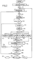
- Number 1 in Figure 1 indicates a character recognition coprocessor in accordance with the teachings of the present invention.
- Coprocessor 1 is a 32-bit SLAVE coprocessor, and cooperates with a known MASTER (or HOST) processor 3 (e.g. an 80386 or 80486 processor), which controls operation of, programs and enables, and reads the data processed by, SLAVE coprocessor 1.
- MASTER or HOST
- 80386 or 80486 processor e.g. an 80386 or 80486 processor
- Coprocessor 1 also cooperates with a known external memory 5, in particular, a static 32-bit memory of maximum 2 Megabytes, which may comprise one or more (e.g. two or four) memory banks.
- Coprocessor 1 comprises a first interface and internal decoding circuit 8 communicating with processor 3 over a two-way data line (BUS) 10 for transmitting data to and from processor 3.
- BUS two-way data line
- Interface circuit 8 also communicates with processor 3 over a data line (BUS) 12 for transmitting control signals from processor 3 to coprocessor 1, and with a data line (BUS) 14 for transmitting addresses from processor 3 to coprocessor 1.
- BUS data line
- BUS data line
- Coprocessor 1 also comprises a second interface and internal decoding circuit 17 communicating with external memory 5 over a two-way data line (BUS) 19 for transmitting data to and from memory 5.
- BUS two-way data line
- Second interface circuit 17 also communicates with memory 5 over a data line (BUS) 21 for transmitting control signals to memory 5, and with a data line (BUS) 23 for transmitting addresses from coprocessor 1 to memory 5.
- BUS data line
- BUS data line
- Coprocessor 1 also comprises a first internal data line (BUS) 26a extending from first interface circuit 8 to second interface circuit 17; and a second internal data line (BUS) 26b extending from second interface circuit 17 to first interface circuit 8.
- BUS first internal data line
- BUS second internal data line
- Internal data lines 26a, 26b also communicate respectively with data lines 32a (input), 32b (output), which communicate with a second internal memory 34 containing, as described later on, a binary matrix of pixels defining a character Cj for recognition.
- Coprocessor 1 also comprises an arithmetic logic unit (ALU) 37 with input registers 39 and output registers 41 communicating respectively with second interface circuit 17 and first interface circuit 8 over respective data lines 43, 44.
- ALU arithmetic logic unit
- Input registers 39 are also connected to second internal memory 34 over a data line 48.
- coprocessor 1 provides for PATTERN MATCHING an unknown character Cj and a number of known characters Mi hereinafter referred to as masks.
- Characters Cj are formed by digitizing analog images of handwritten or typewritten alphanumeric characters (letter, numbers, punctuation marks), and are defined by rectangular matrixes of pixels which may assume "0" or "1" binary values (binary bitmaps).
- each character Cj comprises a first set of pixels (of binary value "1") corresponding to the stroke of the character; and a second set of pixels (of binary value "0") corresponding to the background of the digitized character.
- a character Cj is intended to mean the matrix formed by the first and second set of pixels.
- Each character Cj presents a width of 32 bits, and a maximum height of 64 bits, and is therefore defined by a rectangular binary matrix of maximum 32x64 bits.
- Masks Mi are also defined by binary matrixes of maximum 32x64 bits.
- External memory 5 contains masks Mi; characters Cj are transferred to memory 34 for the comparison to be made; and masks Mi and characters Cj are compared, as described later on, by arithmetic logic unit 37, which supplies a number of numeric values Di, each expressing the distance, according to a given measuring system, between the character Cj being examined and a respective mask Mi, and which are subsequently recovered by processor 3.
- FIG. 2 block diagram shows a preferred example of the operation of coprocessor 1, some of the steps described below being performable differently and/or in a different order from those shown, and some of the steps even being dispensable.
- a number of registers 30 R of coprocessor 1 are programmed to permit the coprocessor to operate correctly.
- block 100 programs an IDWAIT register containing a number of parameters defining:
- Block 100 also programs an HLIMMM register indicating the maximum size of external memory 5.
- Block 100 is followed by block 110 in which masks Mi are loaded into external memory 5. More specifically, the data relative to masks Mi transferred by processor 3 is sent to interface circuit 8, along data line 26a to interface circuit 17, and along data line 19 to memory 5.
- Block 115 is followed by block 117 in which character Cj is loaded into memory 34 and unit 37. More specifically, the data relative to character Cj transferred by processor 3 is sent to interface circuit 8 and along data line 26a and data line 32a to memory 34.
- Block 117 also programs a HIGH_CRT register containing the height HC (expressed in 32-bit words) of the character Cj being examined, which height HC, as already stated, ranges from 1 to 64.
- Block 118 is followed by block 120 which programs a STIMM register indicating the pointer value of the mask from which the comparison is to commence.
- Block 120 also programs a COMMAND register containing a number of parameters defining:
- Block 120 is followed by block 130 which waits for a START control register to be enabled.
- block 130 goes on to block 135 which loads a first mask Mi into input unit 39 of arithmetic logic unit 37, to do which, the data of mask Mi is sent from external memory 5 along line 19 to circuit 17, and along line 43 to unit 37.
- Block 130 may be simultaneous with block 120.
- Block 135 is followed by block 140 (described in detail later on) which, if mask Mi and the character Cj in memory 34 differ in height, provides for centering mask Mi to adapt its height HM to that of the character.
- Block 140 is followed by block 145 which, by examining the COMMAND register, determines whether centering of mask Mi has been requested. If it has, block 145 goes on simultaneously to five blocks 150, 151, 152, 153, 154. If it has not, block 145 only goes on to block 154.
- blocks 150, 151, 152, 153, 154 are followed by block 160; if centering has not been requested, block 154 is followed by block 170.
- Block 160 is also followed by block 170.
- Hplus described in detail later on
- Blocks 150, 151, 152, 153 respectively provide for effecting four shifts (left, right, up, down) of mask Mi (referred to as the central mask), and for calculating respective masks Mi-l (LEFT-SHIFT), Mi-r (RIGHT-SHIFT), Mi-u (UP-SHIFT) and Mi-d (DOWN-SHIFT).
- Mask Mi referred to as the central mask
- Blocks 150, 151, 152, 153 respectively provide for effecting four shifts (left, right, up, down) of mask Mi (referred to as the central mask), and for calculating respective masks Mi-l (LEFT-SHIFT), Mi-r (RIGHT-SHIFT), Mi-u (UP-SHIFT) and Mi-d (DOWN-SHIFT).
- masks Mi-l, Mi-r, Mi-u, Mi-d are respectively generated by shifting all the significant pixels of central mask Mi by one pixel towards the left, right, top and bottom edge of the rectangular matrix respectively.
- Figures 6a-6e respectively show a central mask Mi, a left-shift mask Mi-l, a right-shift mask Mi-r, an up-shift mask Mi-u, and a down-shift mask Mi-d relative, in the example, shown to the number "8".
- blocks 150, 151, 152, 153 respectively provide for comparing character Cj, loaded into unit 37, with masks Mi-l (LEFT-SHIFT), Mi-r (RIGHT-SHIFT), Mi-u (UP-SHIFT) and Mi-d (DOWN-SHIFT).
- Each circuit ALU1, ALU2, ALU3, ALU4, ALU5 is therefore supplied with a set of pixels respectively defining mask Mi-l (LEFT-SHIFT), Mi-r (RIGHT-SHIFT), Mi-u (UP-SHIFT), Mi-d (DOWN-SHIFT) and central mask Mi.
- Each circuit ALU1, ALU2, ALU3, ALU4 and ALU5 therefore supplies a distance Di-l (LEFT-SHIFT), Di-r (RIGHT-SHIFT), Di-u (UP-SHIFT), Di-d (DOWN-SHIFT) and Di indicating the "distance" between the mask at the input and character Cj.
- block 160 selects the minimum value (Dimin-shift), which, of central mask Mi and its shifts, corresponds to the mask most closely resembling character Cj, and which is memorized in a buffer memory.
- block 160 selects the winning mask with the following order of precedence:
- block 170 selects the minimum value (Dimin-abs), which corresponds to a mask Mi-max ("winning" mask) most closely resembling character Cj. That is, of all the masks in the class, and of all the shifts made of them, mask Mi-max is the one most closely "resembling" character Cj. More specifically, of the newly calculated and previously calculated winning masks, block 170 selects the lesser of the two, and repetition of the above operations for an entire class of masks provides for determining mask Mi-max.
- Block 170 provides for programming a WINADRR register, by loading the address of the winning mask Mi-max, the minimum distance value Dimin, and the winning mask code (central, right-shift, left-shift, up-shift, down-shift).
- Block 170 is followed by block 175 which determines whether all the masks NUMMSK in the class have been compared with character Cj.
- Block 180 is followed by block 185 which determines whether all the classes for comparison have been compared with character Cj.
- block 185 goes on to block 190; if they have not, block 185 goes back to block 118.
- Block 192 goes back to block 117 which provides for loading another character Cj+1 into unit 37.
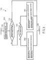
- Figure 3 shows a detail of block 140 for centering mask Mi in relation to character Cj.
- block 140 comprises a first block 300 for determining the height HC of character Cj and the height HM of the mask Mi currently being used.
- difference K is other than zero (i.e. if the mask and the character are of different height)
- block 310 goes on to block 320; conversely (i.e. if the mask and the character are the same height), block 310 goes on to block 145 ( Figures 2 and 3).
- Block 320 determines whether whole number K is an even number, and, if it is, goes on to block 330; conversely (K an odd number), block 320 goes on to block 340.
- block 330 adds K/2 rows of zero pixels over the top row of mask Mi, and K/2 rows of zero pixels beneath the bottom row of mask Mi to which is added a total of K rows of zeroes, so that the modified mask Mi presents the same height as character Cj.
- block 330 adds K/2 rows of zero pixels over the top row of character Cj, and K/2 rows of zero pixels beneath the bottom row of character Cj to which is added a total of K rows of zeroes, so that the modified character Cj presents the same height as mask Mi.
- block 340 adds WHOLE(K/2) rows of zero pixels over the top row of mask Mi, and WHOLE(K/2) + 1 rows of zero pixels beneath the bottom row of mask Mi to which is added a total of K rows of zeroes, so that the modified mask Mi presents the same height as character Cj.
- block 340 adds WHOLE(K/2) rows of zero pixels over the top row of character Cj, and WHOLE(K/2) + 1 rows of zero pixels beneath the bottom row of character Cj to which is added a total of K rows of zeroes, so that the modified character Cj presents the same height as mask Mi.
- Blocks 330, 340 go on to block 145 ( Figures 2 and 3).
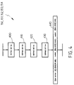
- Figures 4 and 5a-5i show the operations performed by blocks 150-154 to compare mask Mi and character Cj.
- the mask will be indicated by the letter M and the character by the letter C.
- the above pixels define the inner contour (Figure 5c) of the set of "1" pixels in the alphanumeric character represented in matrix C.
- the above pixels define the inner contour ( Figure 5d) of the set of pixels corresponding to the stroke of the digitized alphanumeric character.
- FIGS 5a-5i show the operations performed by blocks 150-154:
- coprocessor 1 presents a maximum operating speed of 33 MHz, and is housed in a 160-pin PQFP surface-mounted container.
- Coprocessor 1 therefore provides for rapidly comparing an unknown character Cj with one or more classes of masks Mi to determine the mask most closely resembling character Cj, and is capable of processing hundreds of characters a second, depending on the number of masks compared, the clock, and the type of MASTER processor employed.
- the algorithm [3] used in unit 37 is extremely effective, and provides for enhancing recognition capacity and greatly reducing the error factor of known systems.
- the centering operation performed by block 145 provides for improving the character recognition rate.
- the centering operation performed by block 140 provides for comparing characters and masks of different height.
- Coprocessor 1 may also operate with memories of different sizes and access times, by virtue of the characteristic parameters of the memory being adjustable by means of the IDWAIT register.
- the coprocessor is extremely cheap to produce.
- coprocessor 1 may also be used in modular structures featuring a variable number of coprocessors operating in parallel and controlled by a single MASTER processor.
- the coprocessors may share a single external memory containing the same class of masks, or each coprocessor may be provided with a respective external memory containing a respective class of masks.
Landscapes
- Engineering & Computer Science (AREA)
- Computer Vision & Pattern Recognition (AREA)
- Theoretical Computer Science (AREA)
- Medical Informatics (AREA)
- Computing Systems (AREA)
- Databases & Information Systems (AREA)
- Evolutionary Computation (AREA)
- General Health & Medical Sciences (AREA)
- Artificial Intelligence (AREA)
- Software Systems (AREA)
- Health & Medical Sciences (AREA)
- Physics & Mathematics (AREA)
- General Physics & Mathematics (AREA)
- Multimedia (AREA)
- Character Input (AREA)
- Image Processing (AREA)
Abstract

Description
- The present invention relates to a character recognition coprocessor.
- SLAVE coprocessors are known which cooperate with and are controlled by a MASTER processor, which enables and programs the coprocessor and reads the data processed by it.
- Such coprocessors may cooperate with an external memory containing operating data used by the coprocessor.
- It is an object of the present invention to provide a SLAVE coprocessor of the above type, which may be used to advantage in OCR (Optical Character Recognition) processes.
- More specifically, it is an object of the present invention to provide a coprocessor for comparing unknown characters (comprising a rectangular matrix of pixels, the binary value of which corresponds to the stroke/background of a digitized alphanumeric character) with reference masks.
- According to the present invention, there is provided a SLAVE character recognition coprocessor connectable to a MASTER processor and cooperating with at least one external memory; characterized in that it comprises:
- first interface and internal decoding means (8) communicating with said processor;
- second interface and internal decoding means (17) communicating with said external memory;
- at least one internal data line extending between said first interface means and said second interface means; and
- at least one internal memory communicating with said internal data line;
said internal memory containing at least one character (Cj) comprising a rectangular binary matrix of pixels;
each character (Cj) comprising a first type of pixel presenting a first binary value ("1") and corresponding to the stroke of a digitized alphanumeric character, and a second type of pixel presenting a second binary value ("0") and corresponding to the background of the alphanumeric character;
said external memory containing a number of reference masks (Mi), each comprising a rectangular binary matrix of pixels;
said number of masks defining a class of masks comparable with said character;
said coprocessor also comprising an electronic arithmetic unit communicating at the input with said second interface means and with said internal memory;
said electronic arithmetic unit communicating at the output with said MASTER processor;
said electronic arithmetic unit comparing a character (Cj) with at least one said mask (Mi), and calculating at least one distance (Di) representing the difference between the character (Cj) and the mask (Mi). - A preferred, non-limiting embodiment of the present invention will be described by way of example with reference to the accompanying drawings, in which:
- Figure 1 shows a schematic diagram of a character recognition coprocessor in accordance with the teachings of the present invention;
- Figure 2 shows a logic block diagram of the operations performed by the Figure 1 coprocessor;
- Figure 3 shows a detail of a first block in Figure 2;
- Figure 4 shows a detail of a second block in Figure 2;
- Figures 5a-5i and 6a-6e show, graphically, a number of operations performed by the coprocessor according to the present invention.
-
Number 1 in Figure 1 indicates a character recognition coprocessor in accordance with the teachings of the present invention. - Coprocessor 1 is a 32-bit SLAVE coprocessor, and cooperates with a known MASTER (or HOST) processor 3 (e.g. an 80386 or 80486 processor), which controls operation of, programs and enables, and reads the data processed by, SLAVE
coprocessor 1. -
Coprocessor 1 also cooperates with a knownexternal memory 5, in particular, a static 32-bit memory of maximum 2 Megabytes, which may comprise one or more (e.g. two or four) memory banks. -
Coprocessor 1 comprises a first interface andinternal decoding circuit 8 communicating with processor 3 over a two-way data line (BUS) 10 for transmitting data to and from processor 3. -
Interface circuit 8 also communicates with processor 3 over a data line (BUS) 12 for transmitting control signals from processor 3 tocoprocessor 1, and with a data line (BUS) 14 for transmitting addresses from processor 3 tocoprocessor 1. -
Coprocessor 1 also comprises a second interface andinternal decoding circuit 17 communicating withexternal memory 5 over a two-way data line (BUS) 19 for transmitting data to and frommemory 5. -
Second interface circuit 17 also communicates withmemory 5 over a data line (BUS) 21 for transmitting control signals tomemory 5, and with a data line (BUS) 23 for transmitting addresses fromcoprocessor 1 tomemory 5. -
Coprocessor 1 also comprises a first internal data line (BUS) 26a extending fromfirst interface circuit 8 tosecond interface circuit 17; and a second internal data line (BUS) 26b extending fromsecond interface circuit 17 tofirst interface circuit 8. - From
internal data lines respective data lines -
Internal data lines data lines 32a (input), 32b (output), which communicate with a secondinternal memory 34 containing, as described later on, a binary matrix of pixels defining a character Cj for recognition. -
Coprocessor 1 also comprises an arithmetic logic unit (ALU) 37 withinput registers 39 andoutput registers 41 communicating respectively withsecond interface circuit 17 andfirst interface circuit 8 overrespective data lines -
Input registers 39 are also connected to secondinternal memory 34 over adata line 48. - As described in detail later on,
coprocessor 1 provides for PATTERN MATCHING an unknown character Cj and a number of known characters Mi hereinafter referred to as masks. - Characters Cj are formed by digitizing analog images of handwritten or typewritten alphanumeric characters (letter, numbers, punctuation marks), and are defined by rectangular matrixes of pixels which may assume "0" or "1" binary values (binary bitmaps).
- More specifically, each character Cj comprises a first set of pixels (of binary value "1") corresponding to the stroke of the character; and a second set of pixels (of binary value "0") corresponding to the background of the digitized character.
- In the following description, a character Cj is intended to mean the matrix formed by the first and second set of pixels.
- Each character Cj presents a width of 32 bits, and a maximum height of 64 bits, and is therefore defined by a rectangular binary matrix of maximum 32x64 bits.
- Masks Mi are also defined by binary matrixes of maximum 32x64 bits.
-
External memory 5 contains masks Mi; characters Cj are transferred tomemory 34 for the comparison to be made; and masks Mi and characters Cj are compared, as described later on, byarithmetic logic unit 37, which supplies a number of numeric values Di, each expressing the distance, according to a given measuring system, between the character Cj being examined and a respective mask Mi, and which are subsequently recovered by processor 3. - The operations performed by
coprocessor 1 according to the present invention will now be described with reference to the block diagram in Figure 2. - The Figure 2 block diagram shows a preferred example of the operation of
coprocessor 1, some of the steps described below being performable differently and/or in a different order from those shown, and some of the steps even being dispensable. - Some of the operations described sequentially may also be performed in parallel.
- In the
first block 100, a number of registers 30 R ofcoprocessor 1 are programmed to permit the coprocessor to operate correctly. In particular, block 100 programs an IDWAIT register containing a number of parameters defining: - the identification of
coprocessor 1; - the number of wait steps with which to access
external memory 5; - the number of memory banks in
external memory 5; - the
coprocessor 1 access mode (INTERRUPT or POLLING); - format details of the output data of
coprocessor 1. -
Block 100 also programs an HLIMMM register indicating the maximum size ofexternal memory 5. -
Block 100 is followed byblock 110 in which masks Mi are loaded intoexternal memory 5. More specifically, the data relative to masks Mi transferred by processor 3 is sent tointerface circuit 8, alongdata line 26a tointerface circuit 17, and alongdata line 19 tomemory 5. -
Block 110 is followed byblock 115 which performs a logic operation j=0 to reset a first variable j. -
Block 115 is followed byblock 117 in which character Cj is loaded intomemory 34 andunit 37. More specifically, the data relative to character Cj transferred by processor 3 is sent tointerface circuit 8 and alongdata line 26a anddata line 32a tomemory 34. -
Block 117 also programs a HIGH_CRT register containing the height HC (expressed in 32-bit words) of the character Cj being examined, which height HC, as already stated, ranges from 1 to 64. -
Block 117 is followed byblock 118 which performs a logic operation i=0 to reset a second variable i. -
Block 118 is followed byblock 120 which programs a STIMM register indicating the pointer value of the mask from which the comparison is to commence. -
Block 120 also programs a COMMAND register containing a number of parameters defining: - the maximum number NUMMSK of masks to be compared with character Cj (the maximum number of masks NUMMSK to be compared with a character normally corresponds to a class of masks);
- enabling/disabling of the mask centering function (described later on).
-
Block 120 is followed byblock 130 which waits for a START control register to be enabled. When it is (START=1), block 130 goes on to block 135 which loads a first mask Mi intoinput unit 39 ofarithmetic logic unit 37, to do which, the data of mask Mi is sent fromexternal memory 5 alongline 19 tocircuit 17, and alongline 43 tounit 37.Block 130 may be simultaneous withblock 120. -
Block 135 is followed by block 140 (described in detail later on) which, if mask Mi and the character Cj inmemory 34 differ in height, provides for centering mask Mi to adapt its height HM to that of the character. -
Block 140 is followed byblock 145 which, by examining the COMMAND register, determines whether centering of mask Mi has been requested. If it has, block 145 goes on simultaneously to fiveblocks - If centering has been requested, blocks 150, 151, 152, 153, 154 are followed by
block 160; if centering has not been requested, block 154 is followed byblock 170. -
Block 160 is also followed byblock 170. -
Block 154 compares character Cj with the mask Mi loaded inblock 135, by means of an algorithm Hplus (described in detail later on) which supplies at the output a distance Di representing a measurement of the difference between character Cj and reference mask Mi according to the equation:
-
Blocks - Since mask Mi is defined by a rectangular matrix of pixels, masks Mi-l, Mi-r, Mi-u, Mi-d are respectively generated by shifting all the significant pixels of central mask Mi by one pixel towards the left, right, top and bottom edge of the rectangular matrix respectively. Figures 6a-6e respectively show a central mask Mi, a left-shift mask Mi-l, a right-shift mask Mi-r, an up-shift mask Mi-u, and a down-shift mask Mi-d relative, in the example, shown to the number "8".
- By means of the Hplus algorithm [1], blocks 150, 151, 152, 153 respectively provide for comparing character Cj, loaded into
unit 37, with masks Mi-l (LEFT-SHIFT), Mi-r (RIGHT-SHIFT), Mi-u (UP-SHIFT) and Mi-d (DOWN-SHIFT). - The operations in
blocks arithmetic logic unit 37. - Each circuit ALU1, ALU2, ALU3, ALU4, ALU5 is therefore supplied with a set of pixels respectively defining mask Mi-l (LEFT-SHIFT), Mi-r (RIGHT-SHIFT), Mi-u (UP-SHIFT), Mi-d (DOWN-SHIFT) and central mask Mi.
- Each circuit ALU1, ALU2, ALU3, ALU4 and ALU5 therefore supplies a distance Di-l (LEFT-SHIFT), Di-r (RIGHT-SHIFT), Di-u (UP-SHIFT), Di-d (DOWN-SHIFT) and Di indicating the "distance" between the mask at the input and character Cj.
- From all the distance values Di-l, Di-r, Di-u, Di-d and Di calculated by
blocks - In the event the same distance is calculated in blocks 150-154, block 160 selects the winning mask with the following order of precedence:
- 1) central mask Mi:
- 2) right-shift mask Mi-r;
- 3) left-shift mask Mi-l;
- 4) up-shift mask Mi-u;
- 5) down-shift mask Mi-d.
- From the Di values calculated successively in
block 154 and the Dimin-shift values calculated in block 160 (if centering is requested), block 170 selects the minimum value (Dimin-abs), which corresponds to a mask Mi-max ("winning" mask) most closely resembling character Cj. That is, of all the masks in the class, and of all the shifts made of them, mask Mi-max is the one most closely "resembling" character Cj. More specifically, of the newly calculated and previously calculated winning masks, block 170 selects the lesser of the two, and repetition of the above operations for an entire class of masks provides for determining mask Mi-max. - In the event two successive masks present the same distance, the value calculated first is selected.
-
Block 170 provides for programming a WINADRR register, by loading the address of the winning mask Mi-max, the minimum distance value Dimin, and the winning mask code (central, right-shift, left-shift, up-shift, down-shift). -
Block 170 is followed byblock 175 which determines whether all the masks NUMMSK in the class have been compared with character Cj. - If they have, block 175 goes on to block 180; if they have not, block 175 goes on to block 176 which increases variable i by one unit (i=i+1) to select the next mask in
memory 5, and then goes back to block 135 which loads another mask Mi+1 intounit 37. - In
block 180, the Dimin-abs value and the address of the winning mask Mi-max are read by processor 3. -
Block 180 is followed byblock 185 which determines whether all the classes for comparison have been compared with character Cj. - If they have, block 185 goes on to block 190; if they have not, block 185 goes back to block 118.
-
Block 190 determines whether any more characters are to be recognized. In the event of a negative response, block 190 goes on to end block 191; in the event of a positive response, block 190 goes on to block 192 which increases character variable j by one unit (j=j+1) to request another character for recognition. -
Block 192 goes back to block 117 which provides for loading another character Cj+1 intounit 37. - Figure 3 shows a detail of
block 140 for centering mask Mi in relation to character Cj. - More specifically, block 140 comprises a
first block 300 for determining the height HC of character Cj and the height HM of the mask Mi currently being used. -
Block 300 is followed byblock 310 which calculates the absolute value of the difference between the height HC of the character and the height HM of the mask according to the equation:
- If difference K is other than zero (i.e. if the mask and the character are of different height), block 310 goes on to block 320; conversely (i.e. if the mask and the character are the same height), block 310 goes on to block 145 (Figures 2 and 3).
-
Block 320 determines whether whole number K is an even number, and, if it is, goes on to block 330; conversely (K an odd number), block 320 goes on to block 340. - In the event height HM of the mask is less than height HC of the character, block 330 adds K/2 rows of zero pixels over the top row of mask Mi, and K/2 rows of zero pixels beneath the bottom row of mask Mi to which is added a total of K rows of zeroes, so that the modified mask Mi presents the same height as character Cj. In the event the height HC of the character is less than the height HM of the mask, block 330 adds K/2 rows of zero pixels over the top row of character Cj, and K/2 rows of zero pixels beneath the bottom row of character Cj to which is added a total of K rows of zeroes, so that the modified character Cj presents the same height as mask Mi.
- In the event height HM of the mask is less than height HC of the character, block 340 adds WHOLE(K/2) rows of zero pixels over the top row of mask Mi, and WHOLE(K/2) + 1 rows of zero pixels beneath the bottom row of mask Mi to which is added a total of K rows of zeroes, so that the modified mask Mi presents the same height as character Cj.
- In the event the height HC of the character is less than the height HM of the mask, block 340 adds WHOLE(K/2) rows of zero pixels over the top row of character Cj, and WHOLE(K/2) + 1 rows of zero pixels beneath the bottom row of character Cj to which is added a total of K rows of zeroes, so that the modified character Cj presents the same height as mask Mi.
-
Blocks - For example, if HC=10 and HM=7, K=3 (odd number), in which case, block 340 adds WHOLE(3/2)=1 row of zeroes over the top row of mask Mi, and WHOLE(3/2)+1 = 2 rows of zeroes beneath the bottom row of mask Mi to which is added a total of 3 rows of zeroes.
- Figures 4 and 5a-5i show the operations performed by blocks 150-154 to compare mask Mi and character Cj.
- For the sake of simplicity, in the following description, the mask will be indicated by the letter M and the character by the letter C.
- Blocks 150-154 comprise a
first block 400 which defines a first set of pixels Bc defined by the pixels p in character C conforming with the following requirements:
p=1 (p is a "1" pixel); and
p is adjacent to at least one "0" pixel in character C. - The above pixels define the inner contour (Figure 5c) of the set of "1" pixels in the alphanumeric character represented in matrix C.
-
Block 400 is followed byblock 410 which defines a second set of pixels Bm defined by the pixels p in mask M conforming with the following requirements:
p=1 (p is a "1" pixel); and
p is adjacent to at least one "0" pixel in mask M. - The above pixels define the inner contour (Figure 5d) of the set of pixels corresponding to the stroke of the digitized alphanumeric character.
-
Block 410 is followed byblock 420 which defines a third set of pixels Ac defined by the pixels p in character C conforming with the following requirements:
p=0 (p is a "0" pixel); and
p is adjacent to at least one "1" pixel in character C. - The above pixels define a contour (Figure 5e) outside the set of "1" pixels of the alphanumeric character represented in matrix C.
-
Block 420 is followed byblock 430 which defines a fourth set of pixels Am defined by the pixels p in mask M conforming with the following requirements:
p=0 (p is a "0" pixel); and
p is adjacent to at least one "1" pixel in mask M. - The above pixels define a contour (Figure 5f) outside the set of "1" pixels of the alphanumeric character represented in mask M.
-
Block 430 is followed byblock 440 which calculates distance D according to the equation:
blocks - Figures 5a-5i show the operations performed by blocks 150-154:
- Figure 5a shows the set of pixels corresponding to a character Cj (in this case, the letter L) for recognition;
- Figure 5b shows the set of pixels corresponding to a reference mask Mi (in this case, the letter L);
- Figure 5c shows the set of pixels Bc;
- Figure 5d shows the set of pixels Bm;
- Figure 5e shows the set of pixels Ac;
- Figure 5f shows the set of pixels Am;
- Figure 5g shows the intersection (AND) of pixel sets Bc and Am (in this case, formed of 8 pixels);
- Figure 5h shows the intersection (AND) of pixel sets Bm and Ac (in this case, formed of 4 pixels);
- Figure 5i shows the EXOR of mask M and character Cj (in this case, formed of 18 pixels).
- When [3] is applied to the above example:

- The present version of
coprocessor 1 presents a maximum operating speed of 33 MHz, and is housed in a 160-pin PQFP surface-mounted container. -
Coprocessor 1 therefore provides for rapidly comparing an unknown character Cj with one or more classes of masks Mi to determine the mask most closely resembling character Cj, and is capable of processing hundreds of characters a second, depending on the number of masks compared, the clock, and the type of MASTER processor employed. - The algorithm [3] used in
unit 37 is extremely effective, and provides for enhancing recognition capacity and greatly reducing the error factor of known systems. - The centering operation performed by
block 145 provides for improving the character recognition rate. - Parallel operation of blocks 150-154 provides for increasing processing speed.
- The centering operation performed by
block 140 provides for comparing characters and masks of different height. -
Coprocessor 1 may also operate with memories of different sizes and access times, by virtue of the characteristic parameters of the memory being adjustable by means of the IDWAIT register. - The coprocessor is extremely cheap to produce.
- And finally,
coprocessor 1 may also be used in modular structures featuring a variable number of coprocessors operating in parallel and controlled by a single MASTER processor. In which case, the coprocessors may share a single external memory containing the same class of masks, or each coprocessor may be provided with a respective external memory containing a respective class of masks. - Clearly, changes may be made to the coprocessor as described and illustrated herein without, however, departing from the scope of the present invention.
Claims (9)
- A SLAVE character recognition coprocessor connectable to a MASTER processor (3) and cooperating with at least one external memory (5); characterized in that it comprises:- first interface and internal decoding means (8) communicating with said processor (3);- second interface and internal decoding means (17) communicating with said external memory (5);- at least one internal data line (26a, 26b) extending between said first interface means (8) and said second interface means (17); and- at least one internal memory (34) communicating with said internal data line (26a, 26b);
said internal memory (34) containing at least one character (Cj) comprising a rectangular binary matrix of pixels;
each character (Cj) comprising a first type of pixel presenting a first binary value ("1") and corresponding to the stroke of a digitized alphanumeric character, and a second type of pixel presenting a second binary value ("0") and corresponding to the background of the alphanumeric character;
said external memory (5) containing a number of reference masks (Mi), each comprising a rectangular binary matrix of pixels;
said number of masks defining a class of masks comparable with said character;
said coprocessor (1) also comprising an electronic arithmetic unit (37) communicating at the input (39) with said second interface means (17) and with said internal memory (34);
said electronic arithmetic unit (37) communicating at the output (41) with said MASTER processor (3);
said electronic arithmetic unit (37) comparing a character (Cj) with at least one said mask (Mi), and calculating at least one distance (Di) representing the difference between the character (Cj) and the mask (Mi). - A coprocessor as claimed in Claim 1, characterized in that said electronic arithmetic unit (37) comprises:- first electronic computing means (400) for defining a first set of pixels Bc comprising the pixels p in the character (Cj) conforming with the following requirements:
p is a pixel of the first type of the character (Cj); and
p is adjacent to at least one pixel of the second type of the character (Cj);- second electronic computing means (410) for defining a second set of pixels Bm comprising the pixels p in the mask (Mi) conforming with the following requirements:
p is a pixel of the first type of the mask (Mi);
p is adjacent to at least one pixel of the second type of the mask (Mi):- third electronic computing means (420) for defining a third set of pixels Ac comprising the pixels p in the character (Cj) conforming with the following requirements:
p is a pixel of the second type of the character (Cj); and
p is adjacent to at least one pixel of the first type of the character (Cj);- fourth electronic computing means (430) for defining a fourth set of pixels Am comprising the pixels p in the mask (Mi) conforming with the following requirements:
p is a pixel of the second type of the mask (Mi); and
p is adjacent to at least one pixel of the first type of the mask (Mi); and- fifth electronic means (440) for calculating said distance (Di) according to an equation of the type:
- A coprocessor as claimed in Claim 1 or 2, characterized in that it comprises centering means (140) for comparing the value (HC) of a dimension of said character (Cj) with the value (HM) of a corresponding dimension of said mask (Mi), and for adapting said dimension (HM) of said mask with said dimension (HC) of said character.
- A coprocessor as claimed in Claim 3, characterized in that said centering means (140) comprise:- means (300) for determining the height (HC) of the character (Cj) and the height (HM) of the mask in use in said electronic arithmetic unit (37);- first comparing means (310) for determining the absolute value K of the difference between said height (HC) of the character and said height (HM) of the mask;- second comparing means (320) selected by said first comparing means (310) if said absolute value K is other than zero, and which determine whether said absolute value K is an even number;- first correcting means (330) selected by said second comparing means (320), for correcting an even said absolute value K, and which provide for adding K/2 rows of pixels of the second type over the top row of the mask in use (Mi), and K/2 rows of pixels of the second type beneath the bottom row of the mask in use (Mi) when the height (HM) of the mask is less than the height (HC) of the character;
said first correcting means (330) adding K/2 rows of pixels of the second type over the top row of the character in use (Cj), and K/2 rows of pixels of the second type beneath the bottom row of the character in use (Cj) when the height (HC) of the character is less than the height (HM) of the mask;- second correcting means (340) selected by said second comparing means (320), for correcting an odd said absolute value K, and which provide for adding WHOLE(K/2) rows of pixels of the second type over the top row of the mask in use (Mi), and WHOLE(K/2) + 1 rows of pixels of the second type beneath the bottom row of the mask in use (Mi) when the height (HM) of the mask is less than the height (HC) of the character;
said second correcting means (340) adding WHOLE(K/2) rows of pixels of the second type over the top row of the character in use (Cj), and WHOLE(K/2) + 1 rows of pixels of the second type beneath the bottom row of the character in use (Cj) when the height (HC) of the character is less than the height (HM) of the mask. - A coprocessor as claimed in any one of the foregoing Claims from 2 to 4, characterized in that it comprises centering means (145) for perpendicularly shifting the mask (Mi) supplied to said arithmetic unit (37), and generating respective left-shift (Mi-l), right-shift (Mi-r), up-shift (Mi-u) and down-shift (Mi-d) masks;
said coprocessor (1) comprising first (150,ALU1), second (151,ALU2), third (152,ALU3) and fourth (153,ALU4) arithmetic circuits respectively supplied with said left-shift (Mi-l), right-shift (Mi-r), up-shift (Mi-u) and down-shift (Mi-d) masks, and generating, by means of said equation, respective intermediate left-shift, right-shift, up-shift and down-shift distances (Di-l, Di-r, Di-u, Di-d);
said coprocessor (1) comprising a fifth arithmetic circuit (154,ALU5) supplied with said mask and generating, by means of said equation, an intermediate centered distance;
said coprocessor (1) also comprising selecting means (170) supplied with said intermediate distances computed by said first (150), second (151), third (152), fourth (153) and fifth (154) arithmetic circuits;
said selecting means (170) computing said distance (Di) by selecting the lesser of said intermediate distances. - A coprocessor as claimed in Claim 5, characterized in that said first (150,ALU1), second (151,ALU2), third (152,ALU3), fourth (153,ALU4) and fifth (154,ALU5) arithmetic circuits operate in parallel.
- A coprocessor as claimed in any one of the foregoing Claims, characterized in that it comprises first electronic initializing means (100, IDWAIT) for initializing a number of parameters defining:- the identification of said coprocessor (1);- the number of wait steps of the external memory (5);- the number of memory banks in the external memory (5);- the coprocessor (1) access mode;- the coprocessor (1) output data format.
- A coprocessor as claimed in any one of the foregoing Claims, characterized in that it comprises second electronic initializing means (100, HLIMMM) for selecting parameters indicating the size of said external memory (5).
- A coprocessor as claimed in any one of the foregoing Claims, characterized in that it comprises third electronic initializing means (120, COMMAND) for initializing a number of parameters defining:- the maximum number (NUMMSK) of masks (Mi) to be compared with the character (Cj);- the type of algorithm used for performing the comparison;- the start address of the external memory (5).
Applications Claiming Priority (2)
| Application Number | Priority Date | Filing Date | Title |
|---|---|---|---|
| ITTO940774 | 1994-09-30 | ||
| IT94TO000774A IT1268611B1 (en) | 1994-09-30 | 1994-09-30 | COPROCESSOR FOR CHARACTER RECOGNITION |
Publications (2)
| Publication Number | Publication Date |
|---|---|
| EP0704817A2 true EP0704817A2 (en) | 1996-04-03 |
| EP0704817A3 EP0704817A3 (en) | 1996-06-05 |
Family
ID=11412802
Family Applications (1)
| Application Number | Title | Priority Date | Filing Date |
|---|---|---|---|
| EP95115347A Withdrawn EP0704817A3 (en) | 1994-09-30 | 1995-09-28 | Coprocessor for pattern matching |
Country Status (3)
| Country | Link |
|---|---|
| US (1) | US5787200A (en) |
| EP (1) | EP0704817A3 (en) |
| IT (1) | IT1268611B1 (en) |
Families Citing this family (2)
| Publication number | Priority date | Publication date | Assignee | Title |
|---|---|---|---|---|
| US7185175B2 (en) * | 2004-01-14 | 2007-02-27 | International Business Machines Corporation | Configurable bi-directional bus for communicating between autonomous units |
| US9069547B2 (en) | 2006-09-22 | 2015-06-30 | Intel Corporation | Instruction and logic for processing text strings |
Family Cites Families (11)
| Publication number | Priority date | Publication date | Assignee | Title |
|---|---|---|---|---|
| US3576534A (en) * | 1969-08-11 | 1971-04-27 | Compuscan Inc | Image cross correlator |
| EP0016523B1 (en) * | 1979-02-13 | 1984-09-26 | The Secretary of State for Defence in Her Britannic Majesty's Government of the United Kingdom of Great Britain and | Data processing unit and data processing system comprising a plurality of such data processing units |
| US4380698A (en) * | 1980-07-25 | 1983-04-19 | Roper Corporation | Multiprocessor control bus |
| IT1151351B (en) * | 1982-01-19 | 1986-12-17 | Italtel Spa | CIRCUIT PROVISION SUITABLE TO CARRY OUT THE EXCHANGE OF DATA BETWEEN A COUPLE OF OPERATING PROCESSORS ACCORDING TO THE MASTER-SLAVE PRINCIPLE |
| DE3236299A1 (en) * | 1982-09-30 | 1984-04-05 | Siemens AG, 1000 Berlin und 8000 München | METHOD FOR DIGITALLY CORRELING IMAGE POINT FIELDS FOR DETECTING IMAGE-BASED PATTERNS AND CIRCUIT ARRANGEMENT FOR IMPLEMENTING THE METHOD |
| JPH0743755B2 (en) * | 1985-10-09 | 1995-05-15 | 日本電気株式会社 | Character recognition device |
| JPH0642268B2 (en) * | 1986-10-31 | 1994-06-01 | 日本電気株式会社 | Character recognition device |
| US4985848A (en) * | 1987-09-14 | 1991-01-15 | Visual Information Technologies, Inc. | High speed image processing system using separate data processor and address generator |
| US5321772A (en) * | 1990-03-05 | 1994-06-14 | Honeywell Inc. | Digital image processor |
| JPH0433869A (en) * | 1990-05-31 | 1992-02-05 | Toshiba Corp | Data processor |
| US5546538A (en) * | 1993-12-14 | 1996-08-13 | Intel Corporation | System for processing handwriting written by user of portable computer by server or processing by the computer when the computer no longer communicate with server |
-
1994
- 1994-09-30 IT IT94TO000774A patent/IT1268611B1/en active IP Right Grant
-
1995
- 1995-09-28 EP EP95115347A patent/EP0704817A3/en not_active Withdrawn
- 1995-09-29 US US08/537,282 patent/US5787200A/en not_active Expired - Fee Related
Non-Patent Citations (1)
| Title |
|---|
| None |
Also Published As
| Publication number | Publication date |
|---|---|
| US5787200A (en) | 1998-07-28 |
| EP0704817A3 (en) | 1996-06-05 |
| IT1268611B1 (en) | 1997-03-06 |
| ITTO940774A1 (en) | 1996-03-30 |
| ITTO940774A0 (en) | 1994-09-30 |
Similar Documents
| Publication | Publication Date | Title |
|---|---|---|
| CA1160347A (en) | Method for recognizing a machine encoded character | |
| US4153897A (en) | Method and device for detecting the similarity between standard and unknown patterns | |
| US4167728A (en) | Automatic image processor | |
| EP0279297B1 (en) | Pattern contours in image processing | |
| EP0332779B1 (en) | Apparatus and method for producing output data for a printing operation, and a printer, in combination with the apparatus, for performing the printing operation | |
| US4622546A (en) | Apparatus and method for displaying characters in a bit mapped graphics system | |
| US5430885A (en) | Multi-processor system and co-processor used for the same | |
| US5555320A (en) | Pattern recognition system with improved recognition rate using nonlinear transformation | |
| US3492646A (en) | Cross correlation and decision making apparatus | |
| EP0228776A2 (en) | Extraction of features from a pattern | |
| EP0036150B1 (en) | Pattern recognition system operating by the multiple similarity method | |
| US4322716A (en) | Method and apparatus for pattern recognition and detection | |
| US3990045A (en) | Array logic fabrication for use in pattern recognition equipments and the like | |
| US6408091B1 (en) | Information processing method and apparatus with mixing of processing command input strokes and input strokes for patterns | |
| US4975974A (en) | Character recognition apparatus | |
| EP0149188B1 (en) | Display control system | |
| CN109389110A (en) | A kind of area determination method and device | |
| US5237649A (en) | Method and system for acquiring interpolation points from straight short vectors representing figure in curve fitting | |
| US4776024A (en) | System for segmenting character components | |
| US4048615A (en) | Automated character recognition system | |
| US5202671A (en) | Pick function implementation in a parallel processing system | |
| US5787200A (en) | Character recognition coprocessor | |
| US4339751A (en) | Marine radar including anticollision unit | |
| US3987410A (en) | Array logic fabrication for use in pattern recognition equipments and the like | |
| CA2023832C (en) | Method and apparatus for filing contours in digital typefaces |
Legal Events
| Date | Code | Title | Description |
|---|---|---|---|
| PUAI | Public reference made under article 153(3) epc to a published international application that has entered the european phase |
Free format text: ORIGINAL CODE: 0009012 |
|
| AK | Designated contracting states |
Kind code of ref document: A2 Designated state(s): DE FR NL |
|
| PUAL | Search report despatched |
Free format text: ORIGINAL CODE: 0009013 |
|
| AK | Designated contracting states |
Kind code of ref document: A3 Designated state(s): DE FR NL |
|
| 17P | Request for examination filed |
Effective date: 19961204 |
|
| RAP1 | Party data changed (applicant data changed or rights of an application transferred) |
Owner name: ELSAG SPA |
|
| 17Q | First examination report despatched |
Effective date: 19991209 |
|
| STAA | Information on the status of an ep patent application or granted ep patent |
Free format text: STATUS: THE APPLICATION IS DEEMED TO BE WITHDRAWN |
|
| 18D | Application deemed to be withdrawn |
Effective date: 20000420 |