EP0706155A1 - Method and device for encoding image signal and image signal decoding device - Google Patents
Method and device for encoding image signal and image signal decoding device Download PDFInfo
- Publication number
- EP0706155A1 EP0706155A1 EP95916022A EP95916022A EP0706155A1 EP 0706155 A1 EP0706155 A1 EP 0706155A1 EP 95916022 A EP95916022 A EP 95916022A EP 95916022 A EP95916022 A EP 95916022A EP 0706155 A1 EP0706155 A1 EP 0706155A1
- Authority
- EP
- European Patent Office
- Prior art keywords
- component
- video signal
- coding
- signal
- edge
- Prior art date
- Legal status (The legal status is an assumption and is not a legal conclusion. Google has not performed a legal analysis and makes no representation as to the accuracy of the status listed.)
- Withdrawn
Links
Images


Classifications
-
- G—PHYSICS
- G06—COMPUTING; CALCULATING OR COUNTING
- G06T—IMAGE DATA PROCESSING OR GENERATION, IN GENERAL
- G06T9/00—Image coding
-
- G—PHYSICS
- G06—COMPUTING; CALCULATING OR COUNTING
- G06T—IMAGE DATA PROCESSING OR GENERATION, IN GENERAL
- G06T9/00—Image coding
- G06T9/20—Contour coding, e.g. using detection of edges
-
- H—ELECTRICITY
- H04—ELECTRIC COMMUNICATION TECHNIQUE
- H04N—PICTORIAL COMMUNICATION, e.g. TELEVISION
- H04N19/00—Methods or arrangements for coding, decoding, compressing or decompressing digital video signals
- H04N19/20—Methods or arrangements for coding, decoding, compressing or decompressing digital video signals using video object coding
-
- H—ELECTRICITY
- H04—ELECTRIC COMMUNICATION TECHNIQUE
- H04N—PICTORIAL COMMUNICATION, e.g. TELEVISION
- H04N19/00—Methods or arrangements for coding, decoding, compressing or decompressing digital video signals
- H04N19/30—Methods or arrangements for coding, decoding, compressing or decompressing digital video signals using hierarchical techniques, e.g. scalability
Definitions
- the present invention relates to a video signal coding method and an apparatus thereof, and a video signal decoding method and an apparatus thereof, and more particularly is applicable to which decompose the video signal into plural components in consideration of visual importance of the video signal and then code and decode it. Further, the present invention relates to an edge detecting method and an apparatus thereof which is suitable for aforesaid decomposition.
- transformation coding is widely used for image compression.
- the success of these techniques, beside their energy compaction properties resides in the fact that the distortions due to compression appear in an indirect manner in the spatial domain, namely through the frequency domain components. This leads into a more pleasant distortion, in general.
- the frequency domain distortions in areas containing edges for instance lead into less desirable artifacts, such as ringing.
- a solution to reduce this drawback is to classify different regions of the image (commonly square blocks), and to apply different quantization strategies, to each distinct class.
- the criterion of classification is of great importance.
- a measure of the activity based on the AC values of the transform coefficients of each region (block) is usually used. Classification based on activity of AC coefficients is rather good to discriminate between smooth regions and other regions with higher frequency contents. But this technique does not work properly to separate regions containing edges and regions having texture-like activities.
- the present invention is to provide a video signal coding method and an apparatus thereof and a video signal decoding method and an apparatus thereof which can be improve visual picture quality of the restored image with higher compression rate then ever.
- a local luminance component composed of smooth component of an input video signal is coded by utilizing a first coding method; luminance edge component composed of contour component of the input video signal is coded by utilizing a second coding method by chain coding; and a texture component composed of the component other than the local luminance component and the luminance edge component is coded by utilizing a third coding method.
- the present invention provides first coding means for generating a first coded signal by coding the local luminance component composed of the smooth component of the input video signal by utilizing the first coding method; second coding means for generating a second coded signal by coding the luminance edge component composed of the contour component of the input video signal by utilizing the second coding method of chain coding; and third coding means for generating a third coded signal by coding the texture component composed of the component other than the local luminance component and the luminance edge component of the input video signal by utilizing the third coding method.
- a video signal decoding method of the present invention for reconstructing the video signal by utilizing the first coded signal generated by coding the local luminance component composed of the smooth component of the input video signal including at least luminance component, the second coded signal generated by coding the luminance edge component composed of the contour component of the input video signal by utilizing the second coding method by the chain coding, and the third coded signal generated by coding the texture component composed of the component other than the local luminance component and the luminance edge component of the input video signal by utilizing the third coding method, wherein: the first coded signal is decoded to generate a reconstruction local luminance; the second coding signal is decoded to generate a reconstruction edge; the edge image is reconstructed based on the reconstruction local luminance component and reconstruction edge component; the third coded signal is decoded to generate a reconstruction texture; and the edge image and the reconstruction texture is added to reconstruct original video signal.
- a video signal decoding apparatus of the present invention for reconstructing the video signal by utilizing the first coded signal generated by coding the local luminance component composed of the smooth component of the input video signal including at least luminance component, the second coded signal generated by coding the luminance edge component composed of the contour component of the input video signal by utilizing the second coding method by the chain coding, and the third coded signal generated by coding the texture component composed of the component other than the local luminance component and the luminance edge component of the input video signal by utilizing the third coding method, comprising: first decoding means for decoding the first coded signal to generate a reconstruction local luminance; second decoding means for decoding the second coded signal to generate a reconstruction edge; means for reconstructing an edge image based on the reconstruction local luminance component and reconstruction edge component; third decoding means for decoding the third coded signal to generate a reconstruction texture; and adding means for adding the edge image and the reconstruction texture to reconstruct the original video signal.
- an edge detecting method of the present invention for detecting the edge of the input video signal comprising: a process of differentiating the input video signal; a process of comparing the differentiated result by the differentiating process with a threshold value adaptively controlled to extract the component more than the threshold value from the differentiated result; a process of detecting a change point from the extracted component; and a process of determining a singular point based on the change point.
- an edge detecting apparatus of the present invention for detecting the edge of the input video signal, comprising: differentiation means for differentiating the input video signal; means for comparing the differentiated result by the differentiating means with a threshold value adaptively controlled to extract the component more than the threshold value from the differentiated result; means for detecting a change point from the extracted component; and means for determining a singular point based on the change point.
- the video signal is resolved into the local luminance information composed of the smooth component, the edge information composed of the contour component, and the texture information composed of the component other than the smooth component and the contour component, and the different coding is performed on each of them corresponding to each visual importance, so that the coding can be performed with higher compression rate than ever and in consideration of the visual picture quality of the restored image. Also, the edge information is detected in consideration of the reconstruction.
- the coded local luminance information is decoded to generate the reconstruction local luminance
- the coded edge information is coded to generate the reconstruction edge information
- the edge image generated based on the reconstruction local luminance and the reconstruction edge information are added to the decoded texture information to reconstruct the original image, so that the coded data can be surely decoded in consideration of visual picture quality of the restored image.
- Fig. 1 is a block diagram showing an embodiment of a video signal coding apparatus according to the present invention.
- Fig. 2 is a block diagram showing an embodiment of a video signal decoding apparatus according to the present invention.
- Fig. 4 is a block diagram showing an edge information detection and coding processing unit in the video signal coding apparatus of Fig. 1.
- Fig. 7 is a block diagram showing a local luminance decoding and reconstruction processing unit in the video signal decoding apparatus of Fig. 2.
- Fig. 8 is a block diagram showing an edge information decoding and reconstruction processing unit in the video signal decoding apparatus of Fig. 2.
- Fig. 9 is a block diagram explaining the brief construction of a chrominance video signal coding apparatus according to the present invention.
- Fig. 10 is a block diagram explaining a reconstruction signal resulted from a singular point detection as an edge detection.
- Figs. 11(A) to 11(E) are schematic diagrams explaining the edges having same discontinuity which causes an erroneous detection when the edge detection.
- Figs. 12(A) to 12(D) are signal waveform diagrams explaining operation of detecting a singular point to the discontinuity which is typical of the edge detection.
- Fig. 13 is a block diagram showing an embodiment of a singular point detecting apparatus as the edge detecting apparatus.
- Figs. 14(A) to 14 (F) are signal waveform diagrams explaining the operation of detecting the singular point and reconstruction at the step edge including noise.
- Figs. 15(A) to 15(D) are signal waveform diagrams explaining the importance of adaptive threshold for detecting the singular point.
- Figs. 16(A) to 16(D) are signal waveform diagrams explaining detection of the change for detecting the singular point and deletion and replacement of a redundant point.
- Figs. 17(A) to 17(D) are signal waveform diagrams explaining the operation of detecting the singular point at the step edge including noise.
- Figs. 18(A) to 18(D) are signal waveform diagrams explaining the operation of detecting the singular point and reconstruction by the conventional Canny method at the step edge including noise.
- Fig. 19 is a block diagram showing the construction of 2-D edge detecting apparatus which is applied a method for detecting the singular point.
- Fig. 20 is a diagram showing an embodiment of a transmission bit stream obtained by the video signal coding apparatus of Fig. 1.
- Fig. 21 shows simulations by 3CC.
- Fig. 21(A) shows the video signal of the original image.
- Fig. 21(B) shows the reconstructed local luminance component.
- Fig. 21(C) shows the edge information.
- Fig. 21(D) shows the edge information after the postprocessing.
- Fig. 21(E) shows the reconstructed edge image.
- Fig. 21(F) shows the texture component.
- Fig. 22 shows comparison between 3CC and JPEG.
- Fig. 22(A) shows the decoded image by 3CC.
- Fig. 22(B) shows the decoded image by JPEG.
- Fig. 22(C) shows the image in which the region of shoulder of the decoded image is enlarged by 3CC.
- Fig. 22(D) shows the image in which the region of shoulder of the decoded image is enlarged by JPEG.
- Fig. 22(E) shows an error image of the decoded image by 3CC.
- Fig 22(F) shows an error image of the decoded image by JPEG.
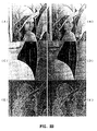
- Fig. 23 shows the detection of the singular point and the reconstruction according to the embodiment.
- Fig. 23(A) shows the original image.
- Fig. 23(B) shows the singular point obtained by a new edge detecting apparatus.
- Fig. 23(C) shows each amplitude of the data reconstructed from the singular point which is after repeating for thirty times by using the diffusion process and the singular point to the original image.
- Fig. 24 shows the detection of singular point and the reconstruction by canny edge detection.
- Fig. 24(A) shows the original image.
- Fig. 24(B) shows the singular point obtained by the canny edge detecting apparatus.
- Fig. 24(C) shows each amplitude of the data reconstructed from the singular point which is after repeating for thirty times by using the diffusion process and the singular point to the original image.r
- chrominance image is compressed by using a three-component coding method (hereinafter referred to as 3CC (3 Component Coding)) in consideration of visual relativity of the image information to be coded. Therefore, the image information is decomposed into three different components, that is, local luminance composed of smooth components, edge information composed of contours, and texture information composed of the other components. The visual importance of these components become larger from the latter toward the former, and allowable distortion in each component changes in accordance with this visual importance. Further, in accordance with those different characteristics, different coding methods are applied to the coding of respective components.
- 3CC Three Component Coding
- this 3CC is a good coding method for classifying the image regions suitably. This method is so efficient for the complicacy of calculation that can be replaced conventional method for detecting activities based on coefficient AC value.
- the fundamental idea of 3CC is simple and so general (X. Ran and N. Farvardin. Low bitrate image coding using a three component image model. Technical Report TR 92-75, University of Maryland, 1992.).
- an original image is decomposed into three different components, namely, a local luminance, an edge information, and a texture information.
- a bitrate which can be used in a specified coding method and between different components is specifically important for entire quality of decoded image. For example, amplitude of the edge is not so important as the edge position. Therefore, although the amplitude information is made quantized simply and roughly, it is enough to obtain visually comfortable image. On the other hand, the edge position information have to be precise as possible.
- 3CC operates more suitable in more wide application (generic coding). For example, in an application having extremely low bitrate, storage of not the texture information but the edge information permits restoration of the image which is more comfortable visually. This is because the contour information is not affected seriously, which is different from conventional coding methods. Further, both the local luminance and the edge information can be decoded by arbitrary resolution without high-level processing. Therefore, coding of the texture information by using multiresolution can realize multiresolution coding easily.
- This embodiment provides new 3CC which can realize high-efficiency transmission with simple construction by further improving aforementioned 3CC.
- Fig. 1, 1 generally shows a video signal coding apparatus by 3CC.
- the coding of luminance signal out of the video signal will be described.
- the coding of chrominance signal out of the video signal is same as the coding of the luminance signal, there is a little difference.
- the video signal coding apparatus which performs coding of the chrominance signal will be described later.
- the video signal coding apparatus 1 is composed of a local luminance generation and coding processing unit 2, an edge information detection and coding processing unit 3, an edge information decoding and reconstruction processing unit 4, a subtraction processing unit 5, and a texture information coding processing unit 6.
- Brightness signal S1 of input video signal is input to the local luminance generation and coding processing unit 2, the edge information detection and coding processing unit 3, and the subtraction processing unit 5, respectively.
- Fig. 2 10 generally shows a video signal decoding apparatus by 3CC which is composed of a local luminance decoding and reconstruction processing unit 11, an edge information decoding and reconstruction processing unit 12, a texture information decoding processing unit 13 and an addition processing unit 14 to which the local luminance component S2, the edge information component S4, and the texture information component S7 are respectively input.
- the local luminance generation and coding processing unit 2 of the video signal coding apparatus 1 is composed of a low pass filter 2A, a down sampling unit 2B, an uniform quantization unit 2C and a PCM coding unit 2D.
- the local luminance generation and coding processing unit 2 in order to obtain local luminance, at first the original luminance signal S1 is filtered by a Gaussian-like low pass filter 2A and then is down sampled at the down sampling unit 2B by an appropriate factor.
- the local luminance output from the low pass filter 2A is also supplied to the edge information decoding and reconstruction processing unit 4.
- position information of those edges are coded along with their amplitude at the contour coding unit 3D and send to the decoding side.
- amplitude of an edge is generally less important than its position.
- luminance of the video signal does not change significantly along with its edge. Therefore, the same amplitude is allotted to all pixels belonging to the same contour.
- the amplitude is the average value of amplitude of all pixels in the contour.
- the position of the contour is coded using a chain coding algorithm.
- the structure of the bit stream for coding the edge information is as shown in Fig. 5; next to height and width of an image, each contour starts by a prefixed number of bits defining the amplitude of all pixels, followed by the length of the chain.
- the subtraction processing unit 5 obtains difference between the input image S1 and the local decoded image, which becomes the texture information.
- Typical texture regions in the image belongs to the texture information, but also non-detected edges of less relevant contours may be sent through this texture information.
- Any classical technique can be used to code the texture information in the texture information coding unit 6.
- the texture information coded in the texture information coding unit 6 is output as the texture information component S7. Because of its smaller perceptual importance, higher compression can be achieved for the texture information. In a case where a coding method with multiresolution data structure is used to code the texture information, 3CC will have a multiresolution characteristic since the local luminance and edge information are actually resolution independent.
- the local luminance decoding and reconstruction processing unit 11 of the video signal decoding apparatus 10 is composed of a PCM decoding unit 11A, an upsampling unit 11B, and a low pass filter 11C.
- the local luminance component S2, the edge information component S4, and the texture information component S7 which are separated from the transmission bit stream by a separation circuit not shown are supplied to the video signal decoding apparatus 10.
- the local luminance component S2 is decoded by the PCM decoding unit 11A, and is input to the upsampling unit 11B.
- This processing of the upsampling unit 11B is equivalent to a zoom of the subsampled luminance information.
- the zoom factor e.g., up sampling factor is equal to the down sampling factor at the encoding side.
- the luminance component is therefore quasi-independent to the resolution of the original image in a certain sense.
- the edge information decoding and reconstruction processing unit 12 is constructed as shown in Fig. 8. First, the edge component S4 is supplied to a contour decoding unit 12A where releases chain coding. Succeedingly, an edge image reconstruction unit 12B restores an edge image S11 by using the decoded edge information and the reconstructed local luminance S10. As described above, the reconstruction of the edge information depends on the technique to extracting the edge information. In this technique, a diffusion process is used similar to the coding side of the edge information decoding and reconstruction processing unit 4 to restore the edge image using the local luminance, the contour position, and the amplitudes. The edge image corresponds to the decoding side of local decoded image. Similar to the local luminance information, the edge information can be decoded by simple coordinate change and desired resolution.
- the texture information component S7 is supplied to the texture information decoding unit 13 where this component is decoded corresponding to the texture information coding unit 6, and then is output as decoded texture information S12.
- the edge image S11 and the decoded texture information S12 are added in the addition processing unit 14, and a reconstructed image S13 can be obtained.
- a chrominance video signal coding apparatus 20 by 3CC is constructed by a combination of a luminance 3CC coding apparatus 1 and a chrominance 3CC coding apparatus 21. Because of the high correlation between the brightness signal S1 and the chrominance signal S20, their edge position information is assumed to be similar.
- the amplitude of the chrominance signals for every chain is calculated and sent to the video signal decoding apparatus.
- a coordinate change is performed to decode the edge information S21 of the luminance signal at the resolution of the chrominance signal S20.
- Fig. 21 shows the original video signal S1 (Fig. 21(A)), the reconstructed local luminance component S2 (Fig. 21(B)), the edge information (Fig. 21(C)), the edge information after postprocessing S4 (Fig. 21(D)), the reconstructed edge image S5 (Fig. 21(E)), and the texture component S7 (Fig. 21(F)), respectively.
- white represents a high energy portion and black represents a low energy portion.
- Fig. 22 shows the texture component by comparing the coded results by 3CC using JPEG algorithm to that of the JPEG algorithm to code the entire image. The simulations were carried on the same image with similar compression rates equal to 12:1.
- Fig. 22 shows the decoded image by 3CC (Fig. 22(A)), the decoded image by JPEG (Fig. 22(B)), an image in which the shoulder area of the decoded image by 3CC is enlarged (Fig. 22(C)), an image in which the shoulder area of the decoded image by JPEG is enlarged (Fig. 22(D)), an error image of the decoded image by 3CC (Fig. 22(E)), an error image of the decoded image by JPEG (Fig. 22(F)), respectively.
- white represents a high energy portion
- black represents a low energy portion.
- the video signal is decomposed into the local luminance information composed of the smooth component, the edge information composed of the contour component, and the texture information composed of the component except for the smooth and contour component.
- the local luminance information is coded by the coding method in which this information is all stored;
- the edge information is coded by the coding method with chain information and constant amplitude information;
- the texture information is coded by the coding method having higher compression rate compared with the local luminance information and the edge information. Therefore, the visual quality of the restored image can be improved with higher compression rate than ever.
- Fig. 10 shows the singular point detection processing and the reconstruction processing to obtain a good approximation of the same signal by decomposing a signal into its singular points, using only the singular points.
- the object of the first block in this diagram is to extract the singular points.
- first and second differential component are used for this edge detection apparatus.
- the problem of edge detection has also been investigated and several edge detection apparatuses have been proposed (J.F. Canny. A computational approach to edge detection. IEEE Trans. on PAMI, 8(6):679-698, November 1986., D. Marr and E.C. Hildreth. Theory of edge detection. In Proc. Roy. Soc. London B, volume 207, pages 187-217, 1980.).
- Figs. 11(A), (B), (C), (D), and (E) For example, an assumption of the various types of edges shown in Figs. 11(A), (B), (C), (D), and (E) is made.
- figures are assumed as the edge of sharp edge (Fig. 11(A)), a smooth edge (Fig. 11(B)), a very smooth edge (Fig. 11(C)), a high contrast (Fig. 11(D)), a low contrast (Fig. 11(E)).
- Conventional edge detection methods find the position of all these edges to be the same. Therefore, the simple position information is not enough to characterize the discontinuities.
- This embodiment represents a new edge detection method for edge detection more suitable for signal reconstruction.
- the second block in Fig. 10 shows the reconstruction processing unit from the singular points.
- Several approaches have been proposed with regard to this reconstruction, each depending on the method used for the singularity detection (S.G. Mallat and S. Zhong. Characterization of signals from multiscale edges. IEEE Trans. on PAMI, 14(7):710-732, 1992., S.G. Mallat and S. Zhong. Singularity detection and processing with wavelets. IEEE Trans. on Information Theory, 38(2):617-643, 1992., S. Carlsson. Sketch based coding of gray level images. Signal Processing, 15(1):57-83, 1988.).
- This embodiment uses the technique proposed in S. Carlsson. Sketch based coding of gray level images. Signal Processing, 15(1):57-83, 1988, for the reconstruction of the signal from its singularities which makes use of a diffusion process. This method is very efficient in computational complexity when compared to the other methods.
- the ultimate purpose of this technique is to detect extra points in signals (in this embodiment, referred to as dominant points) in order to characterize its singularities as precisely as possible, from a signal reconstruction point of view.
- the edge points correspond to local maximum value of the first differential as shown in Fig. 12(B)
- the edge points are located at the zero crossings of the second differential as shown in Fig. 12(C).
- Fig. 12(D) may be more appropriate.
- the dominant point proposed by this embodiment can be used in order to define a summary of the signal around the discontinuities (for instance, by a simple linear interpolation), whereas this is impossible in the case of the singular points detected by conventional edge detection apparatuses using the first differential and the second differential.
- Fig. 13 shows the construction of a singularity detection apparatus 30 of this embodiment, which is composed of a noise reduction processing unit 31, a first differential operating unit 32, a threshold generation processing unit 33, an adoptive threshold processing unit 34, a change detection processing unit 35, and a redundant points removal and replacement processing unit 36.
- Figs. 14(A), (B), (C), (D), (E), and (F) show the case where this singular point detection technique is applied to the original signal composed of step edge including noise.
- Each figure shows the step edge including noise in the original signal (Fig. 14(A)), the signal smoothed by using a Gaussian-like low pass filter (Fig. 14(B)), gradient function and the value of the adaptive threshold (Fig. 14(C)), candidate points as singularities (Fig.
- the noise reduction processing unit 31 improves the quality of the detection based on the first derivative.
- a Gaussian-like low pass filter is used in order to reduce the influence of noise to the first derivative processing in the first derivative processing unit 32.
- Fig. 14(B) shows the result of this stage on the step edge of the original signal including noise shown in Fig. 14(A).
- the kernel (0.25 0.5 0.25) was used as the low pass filter.
- the first derivative processing unit 32 is applied to the result of the noise reduction processing unit 31 at the first stage. All kernel approximating a first derivative can be used at this stage.
- a symmetrical kernel (-1 0 +1) is used in order to prevent the drift in the position detection of the discontinuities.
- the result of the two first stages is equivalent to a gradient detection.
- a threshold is applied in the threshold generation processing unit 33.
- the value of the threshold is dependent on the amount of noise present in the gradient, as well as the local amplitude of the gradient.
- An adaptive thresholding method is therefore used to correctly select the value of the threshold based on the local behavior of the signal. Further, as described above, the value of the threshold depends on two parameters in the adaptive threshold processing unit 34: the noise present in the signal, and the local amplitude of the gradient.
- the operator max( , ) is a maximum operator defined as the following equation:
- ⁇ (k) is the result of an average filtering operation on the absolute value of the gradient of the signal, with a kernel given by (a -w , a -w+1 ... a0 ... a w-1 , a w ).
- ⁇ is the minimum value of the threshold which depends on the amount of noise present in the data.
- Fig. 14(C) shows the gradient as well as the adaptive threshold using the equation (1).
- the value of w in this simulation is selected to be equal to 8 and all the values of the coefficients inside the kernel are put to 1/(2 w + 1).
- the value of ⁇ is equal to 10 in this simulation.
- Figs. 15(A), (B), (C), and (D) Each figure shows the original signal (Fig. 15(A)), gradient and adaptive threshold (Fig. 15(B)), change points (Fig. 15(C)), and the dominant points after removal and replacement of redundant points (Fig. 15(D)). If a constant threshold is selected, in the case of a high threshold (for example, a threshold is constantly set to 40 in Fig.
- Figs. 17(A), (B), (C), and (D) show the operation of the singularity detection applied to a step edge including noise: each of them show the original signal (Fig. 17(A)), the candidate point (Fig. 17(B)), the result of the change detection (Fig. 17(C)), and the result of the removal and replacement of the redundant point (Fig. 17(D)).
- Fig. 17(C) shows an example of the result.
- the redundant point removal and replacement processing unit 36 it is possible to improve the quality of the dominant point detection while reducing their number under the situation described above, using the following simple procedure.
- the resulting candidate points after change detection are examined using a sliding window of size D. If there are at least two candidate points inside the window, respective amplitudes of two candidate points on the original signal are compared. In the case where their difference does not exceed a certain threshold T, both candidates are removed and a new candidate point is created at the middle distance between two previous candidates.
- a result of dominant point detection is shown in Fig. 17(D).
- Fig. 16 shows an example of the case of the aforementioned processing by sample level.
- the adaptive threshold processing unit 34 extracts samples shown in the upper side of Fig. 16(B) as the candidate points.
- the change detection processing unit 35 removes the redundant point from the detected change point by replacement, and then detects samples shown in the upper side of Fig. 16(D) as the dominant points.
- the samples of the original signal corresponding to the positions of the dominant points is considered as the singular points, and the position information of the singular points and their amplitudes are chain-coded in the contour coding unit 3D shown in Fig. 4.
- Figs. 18(A), (B), (C), and (D) show the signal reconstruction using singularities detected by a Canny-like singular point detection which is applied to the step edge including noise as a comparison: each of the figures show the step edge including noise (Fig. 18(A)), the smoothed signal using a Gaussian-like low pass filter (Fig. 18(B)), the absolute value of the first derivative and the edge position as its minimum (Fig. 18(C)), and the result of a reconstruction after repeating a hundred times of diffusion processes using the edge positions (Fig. 18(D)).
- a comparison between the results of this simulation of Fig. 18(D) and that of Fig. 14(D) shows that Fig. 14(D) has the shape more approximate to the original signal, so that this edge detection apparatus outperforms significantly the more conventional apparatus, when the purpose is to reconstruct the signal from discontinuities.
- Fig. 19 shows a 2-D edge detection apparatus 40 in which aforementioned singular point detection and reconstruction is extended into 2-D signal. More specifically, this 2-D edge detection apparatus 40 is constructed by applying two separate 1-D singular point detection procedures along the two axes. Each subblock of this 2-D edge detection apparatus 40 represents the same structure as aforementioned singular point detection apparatus of Fig. 13. Two singular point detection apparatuses 41 and 42 are therefore applied to the 2-D signal in the horizontal and vertical directions independently. The output of every branch is a binary signal equal to one at the singular points. The final result can be obtained from the OR sum of the two branches by an OR circuit 43.
- Fig. 23 shows test images used for this simulation, as well as the result of the 2-D version of the new technique described in the foregoing section.
- the reconstructed image is obtained by using the diffusion process.
- the value of all the parameters are the same as those in the simulation of Fig. 14.
- the same simulation is also carried, two times using Canny edge detection apparatus (same values of the parameters).
- the result of the reconstructed signal is shown in Fig. 24.
- this edge detection technique represents a performance for superior than that of Canny edge detection apparatus from a signal reconstruction point of view.
- Fig. 23 shows the result of reconstruction of the image from singular points obtained by the singular point detection apparatus for a gray scale image: each of them show the original image (Fig. 23(A)), singular points obtained by new edge detection apparatus (Fig. 23(B)), and reconstructed data from the singular points and their respective amplitudes on the original image after repeating a diffusion process for thirty times (Fig. 23(C)).
- Fig. 24 shows the result of reconstruction of the image from singular points obtained by the Canny edge detection apparatus for a gray scale image: each of them show the original image (Fig. 24(A)), singular points obtained by the Canny edge detection apparatus (Fig. 24(B)), and reconstructed data from the singular points and their respective amplitudes on the original image after repeating a diffusion process for thirty times (Fig. 24(C)).
- the video signal is resolved into the local luminance information composed of smooth component, the edge information composed of the contour component, and the texture information composed of components other than the smooth component and the contour component.
- the coding of the local luminance information is performed by a coding method in which the above information is stored.
- the coding of the edge information is performed by a coding method based on the chain information and the constant amplitude information, and the coding of the texture information is performed by a coding method having a higher compressing ratio than the local luminance information and the edge information, thereafter the decoding is performed.
- the coded local luminance information is reconstructed to generate the reconstruction local luminance
- the coded edge information is decoded to generate an edge image based on the reconstruction local luminance
- the coded texture information is decoded
- the edge image is added to the decoded texture information to generate a reconstruction image
- the edge image is generated based on the reconstruction local luminance and the reconstruction edge information are added to the decoded texture information to reconstruct the original image, so that the image signal decoding apparatus in which the coded data can be surely decoded in consideration of visual picture quality of the restored image.
- the video signal coding method and apparatus thereof, and the video signal decoding method and apparatus thereof can be utilized to television telephone systems and television conference systems, etc., which is required the transmission by low bit rate comparatively.
- Video Signal Coding Apparatus 1 ... Video Signal Coding Apparatus, 2 ... Local Luminance Generation and Coding Processing Unit, 3 ... Edge Information Detection And Coding Processing Unit, 4 ... Edge Information Decoding And Reconstruction Processing Unit, 5 ... Subtraction Processing Unit, 6 ... Texture Information Coding Processing Unit, 10 ... Video Signal Decoding Apparatus, 11 ... Local Luminance Decoding And Reconstruction Processing Unit, 12 ... Edge Information Decoding And Reconstruction Processing Unit, 13 ... Texture Information Decoding Processing Unit, 14 ... Addition Processing Unit, 20 ... Chrominance Video Signal Coding Apparatus, 21 ... Chrominance 3CC Coding Apparatus, 30 ... Singular Point Detection Apparatus, 31 ... Noise Reduction Processing Unit, 32 ...
Abstract
A video signal coding method and apparatus thereof and a video signal decoding apparatus of the present invention improves visual picture quality of a decoded image with higher compression rate than ever. A video signal (S1) is resolved into local luminance information composed of the smooth component, edge information composed of contour component, and texture information composed of component other than the smooth component and the contour component corresponding to each different visual importance. Then, the local luminance information is coded (S2) by a coding method which restores all of the local luminance information, the edge information is coded (S4) by a coding method by chain information and amplitude information, and the texture information is coded by a coding method having higher compression rate compared with the local luminance information (S2) and the edge information (S4). The coding can therefore be performed with higher compression rate than ever and in consideration of the visual picture quality of the restored image.
Description
- The present invention relates to a video signal coding method and an apparatus thereof, and a video signal decoding method and an apparatus thereof, and more particularly is applicable to which decompose the video signal into plural components in consideration of visual importance of the video signal and then code and decode it. Further, the present invention relates to an edge detecting method and an apparatus thereof which is suitable for aforesaid decomposition.
- Conventionally, transformation coding is widely used for image compression. The success of these techniques, beside their energy compaction properties resides in the fact that the distortions due to compression appear in an indirect manner in the spatial domain, namely through the frequency domain components. This leads into a more pleasant distortion, in general. However, the frequency domain distortions in areas containing edges for instance, lead into less desirable artifacts, such as ringing. A solution to reduce this drawback is to classify different regions of the image (commonly square blocks), and to apply different quantization strategies, to each distinct class.
- The criterion of classification is of great importance. A measure of the activity based on the AC values of the transform coefficients of each region (block) is usually used. Classification based on activity of AC coefficients is rather good to discriminate between smooth regions and other regions with higher frequency contents. But this technique does not work properly to separate regions containing edges and regions having texture-like activities.
- Although, in general frequency domain distortions are invisible in textures, they become very much visible in presence of edges, because of the ringing artifacts mainly. A good classification should therefore be able to classify edge regions and texture regions appropriately, in order to apply more efficient coding strategies into each class in a further stage. More sophisticated activity detections, based on AC coefficients values may be thought in order to cope with this situation. This will however increase the complexity of the system quite a bit, if an efficient strategy is to be found.
- In view of the foregoing, the present invention is to provide a video signal coding method and an apparatus thereof and a video signal decoding method and an apparatus thereof which can be improve visual picture quality of the restored image with higher compression rate then ever.
- To solve the problem, in the present invention, a local luminance component composed of smooth component of an input video signal is coded by utilizing a first coding method; luminance edge component composed of contour component of the input video signal is coded by utilizing a second coding method by chain coding; and a texture component composed of the component other than the local luminance component and the luminance edge component is coded by utilizing a third coding method.
- Further, the present invention provides first coding means for generating a first coded signal by coding the local luminance component composed of the smooth component of the input video signal by utilizing the first coding method; second coding means for generating a second coded signal by coding the luminance edge component composed of the contour component of the input video signal by utilizing the second coding method of chain coding; and third coding means for generating a third coded signal by coding the texture component composed of the component other than the local luminance component and the luminance edge component of the input video signal by utilizing the third coding method.
- Further, in a video signal decoding method of the present invention for reconstructing the video signal by utilizing the first coded signal generated by coding the local luminance component composed of the smooth component of the input video signal including at least luminance component, the second coded signal generated by coding the luminance edge component composed of the contour component of the input video signal by utilizing the second coding method by the chain coding, and the third coded signal generated by coding the texture component composed of the component other than the local luminance component and the luminance edge component of the input video signal by utilizing the third coding method, wherein: the first coded signal is decoded to generate a reconstruction local luminance; the second coding signal is decoded to generate a reconstruction edge; the edge image is reconstructed based on the reconstruction local luminance component and reconstruction edge component; the third coded signal is decoded to generate a reconstruction texture; and the edge image and the reconstruction texture is added to reconstruct original video signal.
- Further, in a video signal decoding apparatus of the present invention for reconstructing the video signal by utilizing the first coded signal generated by coding the local luminance component composed of the smooth component of the input video signal including at least luminance component, the second coded signal generated by coding the luminance edge component composed of the contour component of the input video signal by utilizing the second coding method by the chain coding, and the third coded signal generated by coding the texture component composed of the component other than the local luminance component and the luminance edge component of the input video signal by utilizing the third coding method, comprising: first decoding means for decoding the first coded signal to generate a reconstruction local luminance; second decoding means for decoding the second coded signal to generate a reconstruction edge; means for reconstructing an edge image based on the reconstruction local luminance component and reconstruction edge component; third decoding means for decoding the third coded signal to generate a reconstruction texture; and adding means for adding the edge image and the reconstruction texture to reconstruct the original video signal.
- Further, in an edge detecting method of the present invention for detecting the edge of the input video signal, comprising: a process of differentiating the input video signal; a process of comparing the differentiated result by the differentiating process with a threshold value adaptively controlled to extract the component more than the threshold value from the differentiated result; a process of detecting a change point from the extracted component; and a process of determining a singular point based on the change point.
- Further, in an edge detecting apparatus of the present invention for detecting the edge of the input video signal, comprising: differentiation means for differentiating the input video signal; means for comparing the differentiated result by the differentiating means with a threshold value adaptively controlled to extract the component more than the threshold value from the differentiated result; means for detecting a change point from the extracted component; and means for determining a singular point based on the change point.
- The video signal is resolved into the local luminance information composed of the smooth component, the edge information composed of the contour component, and the texture information composed of the component other than the smooth component and the contour component, and the different coding is performed on each of them corresponding to each visual importance, so that the coding can be performed with higher compression rate than ever and in consideration of the visual picture quality of the restored image. Also, the edge information is detected in consideration of the reconstruction.
- Further, the coded local luminance information is decoded to generate the reconstruction local luminance, the coded edge information is coded to generate the reconstruction edge information, and the edge image generated based on the reconstruction local luminance and the reconstruction edge information are added to the decoded texture information to reconstruct the original image, so that the coded data can be surely decoded in consideration of visual picture quality of the restored image.
- Fig. 1 is a block diagram showing an embodiment of a video signal coding apparatus according to the present invention.
- Fig. 2 is a block diagram showing an embodiment of a video signal decoding apparatus according to the present invention.
- Fig. 3 is a block diagram showing a local luminance generation and coding processing unit in the video signal coding apparatus of Fig. 1.
- Fig. 4 is a block diagram showing an edge information detection and coding processing unit in the video signal coding apparatus of Fig. 1.
- Fig. 5 is a schematic diagram showing bitstream syntax of the edge information component coded in the edge information detection and coding processing unit of Fig. 4.
- Fig. 6 is a schematic diagram explaining chain coding information of the pixels when coding in the edge information detection and coding processing unit of Fig. 4.
- Fig. 7 is a block diagram showing a local luminance decoding and reconstruction processing unit in the video signal decoding apparatus of Fig. 2.
- Fig. 8 is a block diagram showing an edge information decoding and reconstruction processing unit in the video signal decoding apparatus of Fig. 2.
- Fig. 9 is a block diagram explaining the brief construction of a chrominance video signal coding apparatus according to the present invention.
- Fig. 10 is a block diagram explaining a reconstruction signal resulted from a singular point detection as an edge detection.
- Figs. 11(A) to 11(E) are schematic diagrams explaining the edges having same discontinuity which causes an erroneous detection when the edge detection.
- Figs. 12(A) to 12(D) are signal waveform diagrams explaining operation of detecting a singular point to the discontinuity which is typical of the edge detection.
- Fig. 13 is a block diagram showing an embodiment of a singular point detecting apparatus as the edge detecting apparatus.
- Figs. 14(A) to 14 (F) are signal waveform diagrams explaining the operation of detecting the singular point and reconstruction at the step edge including noise.
- Figs. 15(A) to 15(D) are signal waveform diagrams explaining the importance of adaptive threshold for detecting the singular point.
- Figs. 16(A) to 16(D) are signal waveform diagrams explaining detection of the change for detecting the singular point and deletion and replacement of a redundant point.
- Figs. 17(A) to 17(D) are signal waveform diagrams explaining the operation of detecting the singular point at the step edge including noise.
- Figs. 18(A) to 18(D) are signal waveform diagrams explaining the operation of detecting the singular point and reconstruction by the conventional Canny method at the step edge including noise.
- Fig. 19 is a block diagram showing the construction of 2-D edge detecting apparatus which is applied a method for detecting the singular point.
- Fig. 20 is a diagram showing an embodiment of a transmission bit stream obtained by the video signal coding apparatus of Fig. 1.
- Fig. 21 shows simulations by 3CC. Fig. 21(A) shows the video signal of the original image. Fig. 21(B) shows the reconstructed local luminance component. Fig. 21(C) shows the edge information. Fig. 21(D) shows the edge information after the postprocessing. Fig. 21(E) shows the reconstructed edge image. Fig. 21(F) shows the texture component.
- Fig. 22 shows comparison between 3CC and JPEG. Fig. 22(A) shows the decoded image by 3CC. Fig. 22(B) shows the decoded image by JPEG. Fig. 22(C) shows the image in which the region of shoulder of the decoded image is enlarged by 3CC. Fig. 22(D) shows the image in which the region of shoulder of the decoded image is enlarged by JPEG. Fig. 22(E) shows an error image of the decoded image by 3CC. Fig 22(F) shows an error image of the decoded image by JPEG.
- Fig. 23 shows the detection of the singular point and the reconstruction according to the embodiment. Fig. 23(A) shows the original image. Fig. 23(B) shows the singular point obtained by a new edge detecting apparatus. Fig. 23(C) shows each amplitude of the data reconstructed from the singular point which is after repeating for thirty times by using the diffusion process and the singular point to the original image.
- Fig. 24 shows the detection of singular point and the reconstruction by canny edge detection. Fig. 24(A) shows the original image. Fig. 24(B) shows the singular point obtained by the canny edge detecting apparatus. Fig. 24(C) shows each amplitude of the data reconstructed from the singular point which is after repeating for thirty times by using the diffusion process and the singular point to the original image.r
- Preferred embodiments of the present invention will be described with reference to the accompanying drawings.
- In this embodiment, chrominance image is compressed by using a three-component coding method (hereinafter referred to as 3CC (3 Component Coding)) in consideration of visual relativity of the image information to be coded. Therefore, the image information is decomposed into three different components, that is, local luminance composed of smooth components, edge information composed of contours, and texture information composed of the other components. The visual importance of these components become larger from the latter toward the former, and allowable distortion in each component changes in accordance with this visual importance. Further, in accordance with those different characteristics, different coding methods are applied to the coding of respective components.
- It can be said that this 3CC is a good coding method for classifying the image regions suitably. This method is so efficient for the complicacy of calculation that can be replaced conventional method for detecting activities based on coefficient AC value. The fundamental idea of 3CC is simple and so general (X. Ran and N. Farvardin. Low bitrate image coding using a three component image model. Technical Report TR 92-75, University of Maryland, 1992.).
- In the coding method by 3CC, at first an original image is decomposed into three different components, namely, a local luminance, an edge information, and a texture information. There are several methods to extract these components, each of which generates different results respectively. Besides the method for extracting each component, a bitrate which can be used in a specified coding method and between different components is specifically important for entire quality of decoded image. For example, amplitude of the edge is not so important as the edge position. Therefore, although the amplitude information is made quantized simply and roughly, it is enough to obtain visually comfortable image. On the other hand, the edge position information have to be precise as possible.
- Further, another feature of 3CC is to operate more suitable in more wide application (generic coding). For example, in an application having extremely low bitrate, storage of not the texture information but the edge information permits restoration of the image which is more comfortable visually. This is because the contour information is not affected seriously, which is different from conventional coding methods. Further, both the local luminance and the edge information can be decoded by arbitrary resolution without high-level processing. Therefore, coding of the texture information by using multiresolution can realize multiresolution coding easily. This embodiment provides new 3CC which can realize high-efficiency transmission with simple construction by further improving aforementioned 3CC.
- In Fig. 1, 1 generally shows a video signal coding apparatus by 3CC. Here, the coding of luminance signal out of the video signal will be described. Although the coding of chrominance signal out of the video signal is same as the coding of the luminance signal, there is a little difference. The video signal coding apparatus which performs coding of the chrominance signal will be described later.
- The video
signal coding apparatus 1 is composed of a local luminance generation andcoding processing unit 2, an edge information detection andcoding processing unit 3, an edge information decoding andreconstruction processing unit 4, asubtraction processing unit 5, and a texture informationcoding processing unit 6. Brightness signal S1 of input video signal is input to the local luminance generation andcoding processing unit 2, the edge information detection andcoding processing unit 3, and thesubtraction processing unit 5, respectively. - On the other hand, in Fig. 2, 10 generally shows a video signal decoding apparatus by 3CC which is composed of a local luminance decoding and
reconstruction processing unit 11, an edge information decoding andreconstruction processing unit 12, a texture informationdecoding processing unit 13 and anaddition processing unit 14 to which the local luminance component S2, the edge information component S4, and the texture information component S7 are respectively input. - Here, as shown in Fig. 3, the local luminance generation and
coding processing unit 2 of the videosignal coding apparatus 1 is composed of alow pass filter 2A, adown sampling unit 2B, anuniform quantization unit 2C and aPCM coding unit 2D. In the local luminance generation andcoding processing unit 2, in order to obtain local luminance, at first the original luminance signal S1 is filtered by a Gaussian-likelow pass filter 2A and then is down sampled at thedown sampling unit 2B by an appropriate factor. Incidentally, the local luminance output from thelow pass filter 2A is also supplied to the edge information decoding andreconstruction processing unit 4. - Because of the importance of this local luminance component, the coefficients resultingly generated at the
uniform quantization unit 2C is equally quantized, and then is coded at thePCM coding unit 2D at N-bit/coefficient (N is typically between 8 to 12 bits). The result of this stage corresponds to the DC value of transform based coding. In this manner, in the local luminance generation andcoding processing unit 2, local luminance of the luminance signal S1 is coded to send as the local luminance component S2. As shown in Fig. 4, the edge detection andcoding processing unit 3 is composed of apreprocessing unit 3A, an edgedetection processing unit 3B, apostprocessing unit 3C and a contourcoding processing unit 3D. Thefirst preprocessing unit 3A is performed in order to reduce the influence of noise and texture information to the quality of when detecting the edge. This stage may contain not only a more sophisticated space-variant filtering with stronger effect at texture area an weak or no effect at edges but also a simple low pass filter. Next edgedetection processing unit 3B is an important step along with reconstruction of the edge image. A new method concerning edge detection and image reconstruction from the edge information will be described later. The new edge detection processing is used at this level. However, all other processing methods for reconstructing an image from the edge information can also be used at this stage. Furthermore, thepostprocessing unit 3C removes isolated or less relevant edge and connect contours which are disconnected from each other due to noise. In thispostprocessing unit 3C, a threshold value is set to the degree of intensity in accepting or rejecting relevant edge information in order to control the bitrate of the edge information. - When the most relevant edge is selected, position information of those edges are coded along with their amplitude at the
contour coding unit 3D and send to the decoding side. From a human visual characteristic, amplitude of an edge is generally less important than its position. Furthermore, luminance of the video signal does not change significantly along with its edge. Therefore, the same amplitude is allotted to all pixels belonging to the same contour. Here, the amplitude is the average value of amplitude of all pixels in the contour. The position of the contour is coded using a chain coding algorithm. Actually, the structure of the bit stream for coding the edge information is as shown in Fig. 5; next to height and width of an image, each contour starts by a prefixed number of bits defining the amplitude of all pixels, followed by the length of the chain. - Further, in each chain, the coordinates of the first pixel in the chain are given in absolute values of vertical and horizontal axes, whereas the following pixels in the chain are coded according to their relative position to the previous pixel as shown in Fig. 6. Incidentally, in the figure, a white pixel shows the pixel coded previously, and black pixels show the pixels to be coded presently. A bit ward Wn is used to show the coordinate of new pixels to previous pixels. Since the structure of coding the edge information does not depend on the size of the image completely, reduction or enlargement of the edge information can be obtained by very simple coordinate change when decoding the bit stream. The edge information reconstruction becomes then quasi resolution depending on fractal coding technique in a similar way.
- The remaining information not presented in the local luminance and edge information is defined to be the texture information. Concretely, the texture information is extracted as follows. First, the edge information component S4 being coded edge information is decoded in the edge information decoding and
reconstruction processing unit 4. Further, the edge information decoding andreconstruction processing unit 4 reconstructs the local decoded image from this decoded edge information and the local luminance supplied from thelow pass filter 2A by using the diffusion process. "S. Carlsson. Sketch based coding of gray level images. Signal Processing, 15(1):57-83, 1988", etc., states about the diffusion process in detail. The local decoded image obtained here is similar to the input image S1 to a certain degree. Succeedingly, thesubtraction processing unit 5 obtains difference between the input image S1 and the local decoded image, which becomes the texture information. Typical texture regions in the image belongs to the texture information, but also non-detected edges of less relevant contours may be sent through this texture information. Any classical technique can be used to code the texture information in the textureinformation coding unit 6. The texture information coded in the textureinformation coding unit 6 is output as the texture information component S7. Because of its smaller perceptual importance, higher compression can be achieved for the texture information. In a case where a coding method with multiresolution data structure is used to code the texture information, 3CC will have a multiresolution characteristic since the local luminance and edge information are actually resolution independent. In a multiplexer circuit which is not shown, headers for discriminating respective components are added to the local luminance component S2, the edge information component S4, and the texture information component S7 which are obtained in this manner for one frame, and the components are multiplexed. And then, the components are transmitted as, for example, the bit steam shown in Fig. 20. Incidentally, details of the edge information component part in Fig. 20 is shown in Fig. 5 as described above. - Next, as shown in Fig. 7, the local luminance decoding and
reconstruction processing unit 11 of the videosignal decoding apparatus 10 is composed of aPCM decoding unit 11A, anupsampling unit 11B, and alow pass filter 11C. The local luminance component S2, the edge information component S4, and the texture information component S7 which are separated from the transmission bit stream by a separation circuit not shown are supplied to the videosignal decoding apparatus 10. Virtually, the local luminance component S2 is decoded by thePCM decoding unit 11A, and is input to theupsampling unit 11B. This processing of theupsampling unit 11B is equivalent to a zoom of the subsampled luminance information. The zoom factor, e.g., up sampling factor is equal to the down sampling factor at the encoding side. However, it is possible to transform to the luminance signal having a different resolution, for arbitrary resolution by changing the up-conversion parameters composed of the characteristic of the succeedinglow pass filter 11C and the upsampling factor. The luminance component is therefore quasi-independent to the resolution of the original image in a certain sense. - The edge information decoding and
reconstruction processing unit 12 is constructed as shown in Fig. 8. First, the edge component S4 is supplied to acontour decoding unit 12A where releases chain coding. Succeedingly, an edgeimage reconstruction unit 12B restores an edge image S11 by using the decoded edge information and the reconstructed local luminance S10. As described above, the reconstruction of the edge information depends on the technique to extracting the edge information. In this technique, a diffusion process is used similar to the coding side of the edge information decoding andreconstruction processing unit 4 to restore the edge image using the local luminance, the contour position, and the amplitudes. The edge image corresponds to the decoding side of local decoded image. Similar to the local luminance information, the edge information can be decoded by simple coordinate change and desired resolution. Further, the texture information component S7 is supplied to the textureinformation decoding unit 13 where this component is decoded corresponding to the textureinformation coding unit 6, and then is output as decoded texture information S12. The edge image S11 and the decoded texture information S12 are added in theaddition processing unit 14, and a reconstructed image S13 can be obtained. - The coding and decoding of the video signal by 3CC described above is mentioned about the luminance signal, and the processing of the chrominance signal is similar to that of the brightness signal except for the following point. More specifically, as shown in Fig. 9, a chrominance video
signal coding apparatus 20 by 3CC is constructed by a combination of a luminance3CC coding apparatus 1 and a chrominance3CC coding apparatus 21. Because of the high correlation between the brightness signal S1 and the chrominance signal S20, their edge position information is assumed to be similar. - Therefore there does not need to send a special chain coding information for the chrominance signal S20. However, the amplitude of the chrominance signals for every chain is calculated and sent to the video signal decoding apparatus. In addition, in the case of color image format where the chrominance signals have a lower resolution, a coordinate change is performed to decode the edge information S21 of the luminance signal at the resolution of the chrominance signal S20.
- The processing of the video
signal coding apparatus 1 by 3CC as described above is shown in Figs. 21 and 22 by giving typical images as examples. Fig. 21 shows the original video signal S1 (Fig. 21(A)), the reconstructed local luminance component S2 (Fig. 21(B)), the edge information (Fig. 21(C)), the edge information after postprocessing S4 (Fig. 21(D)), the reconstructed edge image S5 (Fig. 21(E)), and the texture component S7 (Fig. 21(F)), respectively. In the images, white represents a high energy portion and black represents a low energy portion. - Further, Fig. 22 shows the texture component by comparing the coded results by 3CC using JPEG algorithm to that of the JPEG algorithm to code the entire image. The simulations were carried on the same image with similar compression rates equal to 12:1. Fig. 22 shows the decoded image by 3CC (Fig. 22(A)), the decoded image by JPEG (Fig. 22(B)), an image in which the shoulder area of the decoded image by 3CC is enlarged (Fig. 22(C)), an image in which the shoulder area of the decoded image by JPEG is enlarged (Fig. 22(D)), an error image of the decoded image by 3CC (Fig. 22(E)), an error image of the decoded image by JPEG (Fig. 22(F)), respectively. In the images, white represents a high energy portion and black represents a low energy portion.
- As shown in the enlarged area of the shoulder in the test image, the quality of the image in the case of 3CC is superior around contour areas. An observation of the energy of the error of reconstruction in both techniques shows that the error of reconstruction is concentrated at the top of the contour areas and remains imperceptible. The latter is more spread in the case of JPEG algorithm, and lead to annoying by-products, particularly, in the case of moving video images.
- According to the construction described above, the video signal is decomposed into the local luminance information composed of the smooth component, the edge information composed of the contour component, and the texture information composed of the component except for the smooth and contour component. Then, the local luminance information is coded by the coding method in which this information is all stored; the edge information is coded by the coding method with chain information and constant amplitude information; and the texture information is coded by the coding method having higher compression rate compared with the local luminance information and the edge information. Therefore, the visual quality of the restored image can be improved with higher compression rate than ever.
- Here, the description will be given about processing method for the edge detection from the video signal in the edge detection and
coding processing unit 3 and image reconstruction method from the edge information. Signal discontinuities of the video signal and so on represent a very important feature of natural and synthetic signals, and an important portion of the information carried by them is residing in their singular points. Several works have been reported in order to represent signals from their singularities. - In particular, signal representations from zero-crossings or maximum value, e.g., edge detection have been studied in details (R. Hummel and R. Moniot. Reconstructions from zero crossings in scale space. IEEE Trans. on ASSP, 37(12):2111-2130, 1989., S.G. Mallat. Zero-crossings of a wavelet transform. IEEE Trans. on Information Theory, 37(4):1019-1033, 1991., S.G. Mallat and S. Zhong. Characterization of signals from multiscale edges. IEEE Trans. on PAMI, 14(7):710-732, 1992., S.G. Mallat and S. Zhong. Singularity detection and processing with wavelets. IEEE Trans. on Information Theory, 38(2):617-643, 1992.).
- In the case of images, studies of the human visual system show that the edge information which represents singular points is a very important construction component in feature extraction and image understanding. (D. Marr. Vision. W.H. Freeman and Company, New York, 1983., M. Kunt, A. Ikonomopoulos, and M. Kocher. Second generation image coding techniques. Proceedings of the IEEE, 73(4):549-575, April 1985., M. Kunt, M. Bernard, and R. Leonardi. Recent results in high compression image coding. IEEE Trans. on Circuits and Systems, 34(11):1306-1336, November 1987.). Moreover, the reconstruction of a signal from its singularities is very helpful in several applications such as coding, computer vision, signal analysis, and so on.
- Fig. 10 shows the singular point detection processing and the reconstruction processing to obtain a good approximation of the same signal by decomposing a signal into its singular points, using only the singular points. The object of the first block in this diagram is to extract the singular points. In general, first and second differential component are used for this edge detection apparatus. The problem of edge detection has also been investigated and several edge detection apparatuses have been proposed (J.F. Canny. A computational approach to edge detection. IEEE Trans. on PAMI, 8(6):679-698, November 1986., D. Marr and E.C. Hildreth. Theory of edge detection. In Proc. Roy. Soc. London B, volume 207, pages 187-217, 1980.).
- The Canny and the Marr-Hildreth edge detection apparatuses are among the most popular ones which make use of first and second differentials, respectively. The majority of the other edge detection apparatuses are variants of these two techniques. However, the above techniques have been designated to optimize the detection problem under conditions related to feature extraction only, without considering the problem of signal reconstruction from the singularities.
- For example, an assumption of the various types of edges shown in Figs. 11(A), (B), (C), (D), and (E) is made. Incidentally, in Fig. 11, figures are assumed as the edge of sharp edge (Fig. 11(A)), a smooth edge (Fig. 11(B)), a very smooth edge (Fig. 11(C)), a high contrast (Fig. 11(D)), a low contrast (Fig. 11(E)). Conventional edge detection methods find the position of all these edges to be the same. Therefore, the simple position information is not enough to characterize the discontinuities. This embodiment represents a new edge detection method for edge detection more suitable for signal reconstruction.
- The second block in Fig. 10 shows the reconstruction processing unit from the singular points. Several approaches have been proposed with regard to this reconstruction, each depending on the method used for the singularity detection (S.G. Mallat and S. Zhong. Characterization of signals from multiscale edges. IEEE Trans. on PAMI, 14(7):710-732, 1992., S.G. Mallat and S. Zhong. Singularity detection and processing with wavelets. IEEE Trans. on Information Theory, 38(2):617-643, 1992., S. Carlsson. Sketch based coding of gray level images. Signal Processing, 15(1):57-83, 1988.). This embodiment uses the technique proposed in S. Carlsson. Sketch based coding of gray level images. Signal Processing, 15(1):57-83, 1988, for the reconstruction of the signal from its singularities which makes use of a diffusion process. This method is very efficient in computational complexity when compared to the other methods.
- Here, the description will be made about the main parts of the new edge detection method. For simplicity of the description, the description is limited to one-dimensional signal (1-D signal). It is however possible to generalize the same reasoning into n-dimensional signal (n-D signal) case with n > 1. In next section, examples of two-dimensional signal (2-D signal) case will be given for more clarity. For a better understanding of this edge detection method, the results of the procedure which is applied to a step edge including noise is given after every stage by using Figs. 12(A), (B), (C), and (D). Incidentally, each figure shows the original signal (Fig. 12(A)), the absolute value signal of the first differential (Fig. 12(B)), the signal of the second differential (Fig. 12(C)), and the signal showing the dominant point of this embodiment (Fig. 12(D)).
- As described above, the ultimate purpose of this technique is to detect extra points in signals (in this embodiment, referred to as dominant points) in order to characterize its singularities as precisely as possible, from a signal reconstruction point of view. In the case of the first differential based techniques, the edge points correspond to local maximum value of the first differential as shown in Fig. 12(B), whereas in the case of the second differential techniques, the edge points are located at the zero crossings of the second differential as shown in Fig. 12(C).
- Although these methods can correctly find the position of the discontinuities, they fail to completely describe the nature of its discontinuity such as the degree of the sharpness. For this purpose, other points (that is, the dominant points) shown in Fig. 12(D) may be more appropriate. The dominant point proposed by this embodiment can be used in order to define a summary of the signal around the discontinuities (for instance, by a simple linear interpolation), whereas this is impossible in the case of the singular points detected by conventional edge detection apparatuses using the first differential and the second differential.
- Fig. 13 shows the construction of a
singularity detection apparatus 30 of this embodiment, which is composed of a noisereduction processing unit 31, a firstdifferential operating unit 32, a threshold generation processing unit 33, an adoptivethreshold processing unit 34, a changedetection processing unit 35, and a redundant points removal andreplacement processing unit 36. Figs. 14(A), (B), (C), (D), (E), and (F) show the case where this singular point detection technique is applied to the original signal composed of step edge including noise. Each figure shows the step edge including noise in the original signal (Fig. 14(A)), the signal smoothed by using a Gaussian-like low pass filter (Fig. 14(B)), gradient function and the value of the adaptive threshold (Fig. 14(C)), candidate points as singularities (Fig. 14(D)), the dominant points obtained by the algorithm of this embodiment (Fig. 14(E)), and result of a reconstruction after repeating a hundred times of diffusion processes using the dominant points (Fig. 14(F)). Actually, the noisereduction processing unit 31 improves the quality of the detection based on the first derivative. Here, a Gaussian-like low pass filter is used in order to reduce the influence of noise to the first derivative processing in the firstderivative processing unit 32. - The degree of the intense of the low pass filter depends on the amount of noise present in the original data. At this stage, other noise reduction operators can also be used, such as median or morphological filters. Here, Fig. 14(B) shows the result of this stage on the step edge of the original signal including noise shown in Fig. 14(A). In this example, the kernel (0.25 0.5 0.25) was used as the low pass filter.
- Then, the first
derivative processing unit 32 is applied to the result of the noisereduction processing unit 31 at the first stage. All kernel approximating a first derivative can be used at this stage. In the procedure to be described here, a symmetrical kernel (-1 0 +1) is used in order to prevent the drift in the position detection of the discontinuities. The result of the two first stages is equivalent to a gradient detection. - In order to correctly extract the dominant points from noise, a threshold is applied in the threshold generation processing unit 33. The value of the threshold is dependent on the amount of noise present in the gradient, as well as the local amplitude of the gradient. An adaptive thresholding method is therefore used to correctly select the value of the threshold based on the local behavior of the signal. Further, as described above, the value of the threshold depends on two parameters in the adaptive threshold processing unit 34: the noise present in the signal, and the local amplitude of the gradient.
- Actually, at each point, the following equation:


Incidentally, in the equation (1), α(k) is the result of an average filtering operation on the absolute value of the gradient of the signal, with a kernel given by (a-w, a-w+1 ... a₀ ... aw-1, aw). And ε is the minimum value of the threshold which depends on the amount of noise present in the data. Fig. 14(C) shows the gradient as well as the adaptive threshold using the equation (1). The value of w in this simulation is selected to be equal to 8 and all the values of the coefficients inside the kernel are put to 1/(2w + 1). The value of ε is equal to 10 in this simulation. - Here, the description points out the importance of an adaptive thresholding when characterizing sharp and localized transition by using Figs. 15(A), (B), (C), and (D). Each figure shows the original signal (Fig. 15(A)), gradient and adaptive threshold (Fig. 15(B)), change points (Fig. 15(C)), and the dominant points after removal and replacement of redundant points (Fig. 15(D)). If a constant threshold is selected, in the case of a high threshold (for example, a threshold is constantly set to 40 in Fig. 15(B)), some of the important points to characterize the signal will not be detected (i.e., the maximum point of the transition is not detected for its smaller value than 40), whereas in the case of a too small threshold (for example, a threshold is constantly set to 10 in Fig. 15(B)), the position of the characteristic points is not accurate anymore because all points of the sharp transition part exceed the set value.
- In the detection of the dominant points according to this embodiment, all samples with a gradient value above the threshold are considered as candidates to characterize the discontinuity. Although these points can characterize discontinuities in the data, there still exist a certain redundancies among them. The purpose of the following processings is to extract a sample which is considered to be able to characterize discontinuities with an enough good approximation as the dominant point. All other candidates are then discarded. This stage can be divided into the change
detection processing unit 35 and the redundant points removal andreplacement processing unit 36. Incidentally, Figs. 17(A), (B), (C), and (D) show the operation of the singularity detection applied to a step edge including noise: each of them show the original signal (Fig. 17(A)), the candidate point (Fig. 17(B)), the result of the change detection (Fig. 17(C)), and the result of the removal and replacement of the redundant point (Fig. 17(D)). - First, in the change
detection processing unit 35, if neighbors of a candidate point are other candidate points, the candidate point is removed because of the judgment which that candidate is not a change point. In this state, sharp discontinuities are detected as two consecutive step edges. Fig. 17(C) shows an example of the result. Next, in the redundant point removal andreplacement processing unit 36, it is possible to improve the quality of the dominant point detection while reducing their number under the situation described above, using the following simple procedure. - The resulting candidate points after change detection are examined using a sliding window of size D. If there are at least two candidate points inside the window, respective amplitudes of two candidate points on the original signal are compared. In the case where their difference does not exceed a certain threshold T, both candidates are removed and a new candidate point is created at the middle distance between two previous candidates. A result of dominant point detection is shown in Fig. 17(D). The threshold value in this example is selected to be T = 10 and the size of the sliding window is D = 4.
- Fig. 16 shows an example of the case of the aforementioned processing by sample level. If the original signal is the signal shown in Fig. 16(A), the adaptive
threshold processing unit 34 extracts samples shown in the upper side of Fig. 16(B) as the candidate points. Next, the changedetection processing unit 35 removes the redundant point from the detected change point by replacement, and then detects samples shown in the upper side of Fig. 16(D) as the dominant points. The samples of the original signal corresponding to the positions of the dominant points is considered as the singular points, and the position information of the singular points and their amplitudes are chain-coded in thecontour coding unit 3D shown in Fig. 4. - Here, the description will be made about a comparison between the performances of the proposed edge detection apparatus and a conventional edge detection apparatus. Figs. 18(A), (B), (C), and (D) show the signal reconstruction using singularities detected by a Canny-like singular point detection which is applied to the step edge including noise as a comparison: each of the figures show the step edge including noise (Fig. 18(A)), the smoothed signal using a Gaussian-like low pass filter (Fig. 18(B)), the absolute value of the first derivative and the edge position as its minimum (Fig. 18(C)), and the result of a reconstruction after repeating a hundred times of diffusion processes using the edge positions (Fig. 18(D)). A comparison between the results of this simulation of Fig. 18(D) and that of Fig. 14(D) shows that Fig. 14(D) has the shape more approximate to the original signal, so that this edge detection apparatus outperforms significantly the more conventional apparatus, when the purpose is to reconstruct the signal from discontinuities.
- Here, Fig. 19 shows a 2-D
edge detection apparatus 40 in which aforementioned singular point detection and reconstruction is extended into 2-D signal. More specifically, this 2-Dedge detection apparatus 40 is constructed by applying two separate 1-D singular point detection procedures along the two axes. Each subblock of this 2-Dedge detection apparatus 40 represents the same structure as aforementioned singular point detection apparatus of Fig. 13. Two singularpoint detection apparatuses OR circuit 43. - Fig. 23 shows test images used for this simulation, as well as the result of the 2-D version of the new technique described in the foregoing section. The reconstructed image is obtained by using the diffusion process. The value of all the parameters are the same as those in the simulation of Fig. 14. For comparison, the same simulation is also carried, two times using Canny edge detection apparatus (same values of the parameters). The result of the reconstructed signal is shown in Fig. 24. As it can be seen, this edge detection technique represents a performance for superior than that of Canny edge detection apparatus from a signal reconstruction point of view.
- Further, Fig. 23 shows the result of reconstruction of the image from singular points obtained by the singular point detection apparatus for a gray scale image: each of them show the original image (Fig. 23(A)), singular points obtained by new edge detection apparatus (Fig. 23(B)), and reconstructed data from the singular points and their respective amplitudes on the original image after repeating a diffusion process for thirty times (Fig. 23(C)).
- Further, Fig. 24 shows the result of reconstruction of the image from singular points obtained by the Canny edge detection apparatus for a gray scale image: each of them show the original image (Fig. 24(A)), singular points obtained by the Canny edge detection apparatus (Fig. 24(B)), and reconstructed data from the singular points and their respective amplitudes on the original image after repeating a diffusion process for thirty times (Fig. 24(C)).
- As described above, according to the present invention, the video signal is resolved into the local luminance information composed of smooth component, the edge information composed of the contour component, and the texture information composed of components other than the smooth component and the contour component. Then, the coding of the local luminance information is performed by a coding method in which the above information is stored. The coding of the edge information is performed by a coding method based on the chain information and the constant amplitude information, and the coding of the texture information is performed by a coding method having a higher compressing ratio than the local luminance information and the edge information, thereafter the decoding is performed. Thereby, the method for coding a video signal and the apparatus thereof in which the coding can be performed with higher compression rate than ever and in consideration of the visual picture quality of the restored image can be realized.
- Further, the coded local luminance information is reconstructed to generate the reconstruction local luminance, the coded edge information is decoded to generate an edge image based on the reconstruction local luminance, and the coded texture information is decoded, and the edge image is added to the decoded texture information to generate a reconstruction image, the edge image is generated based on the reconstruction local luminance and the reconstruction edge information are added to the decoded texture information to reconstruct the original image, so that the image signal decoding apparatus in which the coded data can be surely decoded in consideration of visual picture quality of the restored image.
- The video signal coding method and apparatus thereof, and the video signal decoding method and apparatus thereof can be utilized to television telephone systems and television conference systems, etc., which is required the transmission by low bit rate comparatively.
- 1 ... Video Signal Coding Apparatus, 2 ... Local Luminance Generation and Coding Processing Unit, 3 ... Edge Information Detection And Coding Processing Unit, 4 ... Edge Information Decoding And Reconstruction Processing Unit, 5 ... Subtraction Processing Unit, 6 ... Texture Information Coding Processing Unit, 10 ... Video Signal Decoding Apparatus, 11 ... Local Luminance Decoding And Reconstruction Processing Unit, 12 ... Edge Information Decoding And Reconstruction Processing Unit, 13 ... Texture Information Decoding Processing Unit, 14 ... Addition Processing Unit, 20 ... Chrominance Video Signal Coding Apparatus, 21 ... Chrominance 3CC Coding Apparatus, 30 ... Singular Point Detection Apparatus, 31 ... Noise Reduction Processing Unit, 32 ... First Derivative Operator Processing Unit, 33 ... Threshold Generation Processing Unit, 34 ... Adaptive Threshold Processing Unit, 35 ... Change Detection Processing Unit, 36 ... Redundant Point Removal and Replacement Processing Unit, 40 ... 2-D Edge Detection Apparatus, 41 ... 1-D Singular Point Detection (Horizontal) Apparatus, 42 ... 1-D Singular Point Detection (Vertical) Apparatus, 43 ... OR Circuit.
Claims (27)
- A video signal coding method for coding an input video signal including at least luminance component, wherein:
local luminance component composed of smooth component of an input video signal is coded by using a first coding method to generate a first coded signal;
luminance edge component composed of contour component of said input video signal is coded by using a second coding method by chain coding to generate a second coded signal; and
texture component composed of component other than said local luminance component and said luminance edge component of said input video signal is coded by using a third coding method to generate a third coded signal. - The video signal coding method according to claim 1, wherein
said texture component is made from the difference between said input video signal and a local decoded image generated based on a signal decoded said local luminance component and said second coding signal. - The video signal coding method according to claim 1, wherein:
said first coding method includes
a process of smoothing said input video signal by using a low pass filter;
a process of down sampling said smoothed signal;
a process of quantizing said down sampled signal; and
a process of PCM coding said quantized signal. - The video signal coding method according to claim 1, wherein
said input video signal includes color difference component, and said color difference component is coded based on edge information of said luminance edge component. - The video signal coding method according to claim 1, wherein
amplitude information in single chain of said second coded signal is represented by single amplitude. - The video signal coding method according to claim 1, wherein
compression rate of said third coding method is higher than that of said first coding method. - The video signal coding method according to claim 1, wherein:
said second coding method includes
a process of differentiating said input video signal;
a process of comparing the result of differentiating with a threshold value adaptively controlled to extract the component more than said threshold value from said result of differentiating;
a process of detecting change points from said extracted component;
a process of determining singular points based on said change points; and
said chain coding is performed to said singular points. - The video signal coding method according to claim 7, wherein
said process of determining singular points includes a process of replacing redundant points among said change points with new points. - A video signal coding apparatus for coding an input video signal including at least luminance component, comprising:
first coding means for coding local luminance component composed of smooth component of an input video signal by using a first coding method to generate a first coded signal;
second coding means for coding luminance edge component composed of contour component of said input video signal by using a second coding method to generate a second coded signal; and
third coding means for coding texture component composed of component other than said local luminance component and said luminance edge component of said input video signal by using a third coding method to generate a third coded signal. - The video signal coding apparatus according to claim 9, wherein:
said texture component is made from the difference between said input video signal and a local decoded image generated based on the signal in which said local luminance component and said second coded signal are decoded. - The video signal coding apparatus according to claim 9, wherein:
said first coding means includes
a low pass filter for smoothing said input video signal;
means for down sampling said smoothed signal;
means for quantizing said down sampled signal; and
means for PCM coding said quantized signal. - The video signal coding apparatus according to claim 9, wherein
said input video signal includes color difference component, and means for coding said color difference component based on the edge information of said luminance edge component is contained. - The video signal coding apparatus according to claim 9, wherein
amplitude information in single chain of said second coded signal is represented by single amplitude. - The video signal coding apparatus according to claim 9, wherein
compression rate of said third coding method is higher than that of said first coding method. - The video signal coding apparatus according to claim 9, wherein:
said second coding method includes
means for differentiating said input video signal;
means for comparing the result of differentiating with a threshold value adaptively controlled to extract the component more than said threshold value from said result of differentiating;
means for detecting change points from said extracted component;
means for determining singular points based on said change points; and
said chain coding is performed to said singular points. - The video signal coding apparatus according to claim 15, wherein
said means for determining singular points replaces redundant points among said change points with new points. - A video signal decoding method for reconstructing a video signal by using a first coded signal generated by coding local luminance component composed of smooth component of an input video signal including at least luminance component, a second coded signal generated by coding luminance edge component composed of contour component of said input video signal, and a third coded signal generated by coding texture component composed of component other than said local luminance component and said luminance edge component of said input video signal, wherein:
said first coded signal is decoded to generate reconstruction local luminance;
said second coded signal is decoded to generate reconstruction edge;
an edge image is reconstructed based on said reconstruction local luminance component and said reconstruction edge component;
said third coded signal is decoded to generate reconstruction texture; and
said edge image and said reconstruction texture are added to reconstruct an original video signal. - The video signal decoding method according to claim 17, wherein:
a process of decoding said first coded signal includes
a process of PCM decoding said first coded signal;
a process of up sampling said PCM decoded signal; and
a process of filtering said up sampled signal by using a low pass filter. - A video signal decoding apparatus for reconstructing a video signal by using a first coded signal generated by coding local luminance component composed of smooth component of an input video signal including at least luminance component, a second coded signal generated by coding luminance edge component composed of contour component of said input video signal, and a third coded signal generated by coding texture component composed of component other than said local component and said luminance edge component of said input video signal, comprising:
first decoding means for decoding said first coded signal to generate reconstruction local luminance;
second decoding means for decoding said second coded signal to generate reconstruction edge;
means for reconstructing an edge image based on said reconstruction local luminance component and said reconstruction edge component;
third decoding means for decoding said third coded signal to generate reconstruction texture; and
adding means for adding said edge image and said reconstruction texture to reconstruct an original video signal. - The video signal decoding apparatus according to claim 19, wherein:
said first decoding means includes
means for PCM decoding said first coded signal;
means for up sampling said PCM decoded signal; and
means for filtering said up sampled signal by using a low pass filter. - A video signal transmission method for transmitting a coded video signal, wherein:
local luminance component composed of smooth component of an input video signal including at least luminance component is coded by using a first coding method to generate a first coded signal to be transmitted;
luminance edge component composed of contour component of said input video signal is coded by using a second coding method by chain coding to generate a second coded signal to be transmitted; and
texture component composed of component other than said local luminance component and said luminance edge component of said input video signal is coded by using a third coding method to generate a third coded signal. - The video signal transmission method according to claim 21, wherein
amplitude information in single chain of said second coded signal is represented by single amplitude. - The video signal transmission method according to claim 21, wherein
single chain of said second coded signal further includes chain length, coordinate information of top pixel of the chain, and relative position information of chain pixels. - An edge detection method for detecting an edge of an input video signal, comprising:
a process of differentiating said input video signal;
a process of comparing the result of differentiating with a threshold value adaptively controlled to extract the component more than said threshold value from said result of differentiating;
a process of detecting change points from said extracted component; and
a process of determining singular points based on said change points. - The edge detection method according to claim 24, wherein
said process of determining singular points includes a process of replacing redundant points among said change points with new points. - An edge detection apparatus for detecting an edge of an input video signal, comprising:
differentiation means for differentiating said input video signal;
means for comparing the result of differentiating by said differentiation means with a threshold value adaptively controlled to extract the component more than said threshold value from said result of differentiating;
means for detecting change points from said extracted component; and
means for determining singular points based on said change points. - The edge detection apparatus according to claim 26, wherein
said means for determining singular points replaces redundant points among said change points with new points.
Applications Claiming Priority (3)
| Application Number | Priority Date | Filing Date | Title |
|---|---|---|---|
| JP10794394 | 1994-04-22 | ||
| JP107943/94 | 1994-04-22 | ||
| PCT/JP1995/000781 WO1995029462A1 (en) | 1994-04-22 | 1995-04-20 | Method and device for encoding image signal and image signal decoding device |
Publications (2)
| Publication Number | Publication Date |
|---|---|
| EP0706155A1 true EP0706155A1 (en) | 1996-04-10 |
| EP0706155A4 EP0706155A4 (en) | 1997-06-11 |
Family
ID=14471988
Family Applications (1)
| Application Number | Title | Priority Date | Filing Date |
|---|---|---|---|
| EP95916022A Withdrawn EP0706155A4 (en) | 1994-04-22 | 1995-04-20 | Method and device for encoding image signal and image signal decoding device |
Country Status (6)
| Country | Link |
|---|---|
| US (1) | US5835237A (en) |
| EP (1) | EP0706155A4 (en) |
| KR (1) | KR960703481A (en) |
| CN (1) | CN1127562A (en) |
| CA (1) | CA2164627A1 (en) |
| WO (1) | WO1995029462A1 (en) |
Cited By (7)
| Publication number | Priority date | Publication date | Assignee | Title |
|---|---|---|---|---|
| WO1997015145A1 (en) * | 1995-10-18 | 1997-04-24 | Philips Electronics N.V. | Region-based texture coding and decoding method, and corresponding systems |
| EP0806871A2 (en) * | 1996-05-10 | 1997-11-12 | Daewoo Electronics Co., Ltd | Method and apparatus for generating chrominance shape information of a video object plane in a video signal |
| EP0817495A2 (en) * | 1996-07-05 | 1998-01-07 | Canon Kabushiki Kaisha | Image subject extraction apparatus and method |
| WO2000003547A2 (en) * | 1998-07-08 | 2000-01-20 | Koninklijke Philips Electronics N.V. | Low bandwidth encoding scheme for video transmission |
| US6453069B1 (en) | 1996-11-20 | 2002-09-17 | Canon Kabushiki Kaisha | Method of extracting image from input image using reference image |
| EP1575297A1 (en) * | 2004-03-11 | 2005-09-14 | Istituto Superiore Mario Boella sulle Tecnologie dell'Informazione e delle Telecomunicazioni | Method and apparatus for edge-based image encoding and decoding |
| CN103067703A (en) * | 2012-12-11 | 2013-04-24 | 渭南高新区晨星专利技术咨询有限公司 | Network video communication system reducing transmission bandwidth and method |
Families Citing this family (56)
| Publication number | Priority date | Publication date | Assignee | Title |
|---|---|---|---|---|
| FR2755527B1 (en) * | 1996-11-07 | 1999-01-08 | Thomson Multimedia Sa | MOTION COMPENSATED PREDICTION METHOD AND ENCODER USING SUCH A METHOD |
| WO1999021285A1 (en) * | 1997-10-23 | 1999-04-29 | Sony Electronics, Inc. | Apparatus and method for recovery of lost/damaged data in a bitstream of data based on compatibility |
| DE69939055D1 (en) * | 1998-03-05 | 2008-08-21 | Matsushita Electric Ind Co Ltd | PICTURE CODING METHOD, PICTURE ENCODING / DECODING METHOD, IMAGE CODING OR PICTURE RECORDING / REPRODUCTION DEVICE |
| JP2000036967A (en) * | 1998-07-21 | 2000-02-02 | Sony Corp | Image processing system and camera system |
| US7137711B1 (en) | 2000-03-21 | 2006-11-21 | Leonard Reiffel | Multi-user retro reflector data input |
| WO2001084475A1 (en) | 2000-05-03 | 2001-11-08 | Leonard Reiffel | Dual mode data imaging product |
| US7034803B1 (en) | 2000-08-18 | 2006-04-25 | Leonard Reiffel | Cursor display privacy product |
| AU2001283375A1 (en) * | 2000-08-18 | 2002-03-04 | Leonard Reiffel | Annotating imaged data product |
| JP2002094994A (en) * | 2000-09-19 | 2002-03-29 | Nec Corp | Moving picture reproduction processing unit and moving picture reproduction processing method |
| JP4294319B2 (en) * | 2000-12-15 | 2009-07-08 | ライフェル レナード | Coded data source tracking device with image display |
| JP4103592B2 (en) * | 2000-12-15 | 2008-06-18 | ライフェル レナード | Multiple imaging devices, multiple data sources, and coded data source data input devices for multiple applications |
| KR100386116B1 (en) * | 2000-12-15 | 2003-06-02 | (주) 멀티비아 | multimedia data coding and decoding system |
| JP4081373B2 (en) * | 2000-12-15 | 2008-04-23 | ライフェル レナード | Coded data source converter by image |
| EP1368787A1 (en) * | 2001-02-28 | 2003-12-10 | PTS Corporation | Dynamic chain-based thresholding |
| EP1390909A4 (en) * | 2001-04-19 | 2004-12-29 | Leonard Reiffel | Combined imaging coded data source data acquisition |
| US20040135766A1 (en) * | 2001-08-15 | 2004-07-15 | Leonard Reiffel | Imaged toggled data input product |
| WO2003021970A1 (en) * | 2001-09-04 | 2003-03-13 | Faroudja Cognition Systems, Inc. | Low bandwidth video compression |
| KR100555419B1 (en) * | 2003-05-23 | 2006-02-24 | 엘지전자 주식회사 | Moving picture coding method |
| US20060291797A1 (en) * | 2003-05-27 | 2006-12-28 | Leonard Reiffel | Multi-imager multi-source multi-use coded data source data input product |
| US7738554B2 (en) | 2003-07-18 | 2010-06-15 | Microsoft Corporation | DC coefficient signaling at small quantization step sizes |
| US7602851B2 (en) | 2003-07-18 | 2009-10-13 | Microsoft Corporation | Intelligent differential quantization of video coding |
| US10554985B2 (en) | 2003-07-18 | 2020-02-04 | Microsoft Technology Licensing, Llc | DC coefficient signaling at small quantization step sizes |
| US8218624B2 (en) | 2003-07-18 | 2012-07-10 | Microsoft Corporation | Fractional quantization step sizes for high bit rates |
| US7580584B2 (en) | 2003-07-18 | 2009-08-25 | Microsoft Corporation | Adaptive multiple quantization |
| US7801383B2 (en) | 2004-05-15 | 2010-09-21 | Microsoft Corporation | Embedded scalar quantizers with arbitrary dead-zone ratios |
| JP2006217406A (en) * | 2005-02-04 | 2006-08-17 | Sony Corp | Coding apparatus and method, decoding apparatus and method, recording medium, program, and image processing system and method |
| JP4530277B2 (en) * | 2005-02-25 | 2010-08-25 | 株式会社リコー | Image reproducing apparatus, image reproducing method, program, and recording medium |
| US8422546B2 (en) | 2005-05-25 | 2013-04-16 | Microsoft Corporation | Adaptive video encoding using a perceptual model |
| JP2006340005A (en) * | 2005-06-01 | 2006-12-14 | Sony Corp | Digital signal processing device and method and program |
| US8059721B2 (en) | 2006-04-07 | 2011-11-15 | Microsoft Corporation | Estimating sample-domain distortion in the transform domain with rounding compensation |
| US8503536B2 (en) | 2006-04-07 | 2013-08-06 | Microsoft Corporation | Quantization adjustments for DC shift artifacts |
| US8130828B2 (en) | 2006-04-07 | 2012-03-06 | Microsoft Corporation | Adjusting quantization to preserve non-zero AC coefficients |
| US7995649B2 (en) | 2006-04-07 | 2011-08-09 | Microsoft Corporation | Quantization adjustment based on texture level |
| US7974340B2 (en) | 2006-04-07 | 2011-07-05 | Microsoft Corporation | Adaptive B-picture quantization control |
| US8711925B2 (en) | 2006-05-05 | 2014-04-29 | Microsoft Corporation | Flexible quantization |
| US7724947B2 (en) * | 2006-09-20 | 2010-05-25 | Qualcomm Incorporated | Removal of background image from whiteboard, blackboard, or document images |
| US8218908B2 (en) * | 2006-11-02 | 2012-07-10 | Canon Kabushiki Kaisha | Mixed content image compression with two edge data representations |
| US8311347B2 (en) * | 2006-11-10 | 2012-11-13 | Microsoft Corporation | Image compression based on parameter-assisted inpainting |
| JP4999865B2 (en) * | 2006-12-28 | 2012-08-15 | 日本電信電話株式会社 | VIDEO PROCESSING METHOD AND DEVICE, VIDEO PROCESSING PROGRAM, AND STORAGE MEDIUM CONTAINING THE PROGRAM |
| US8238424B2 (en) | 2007-02-09 | 2012-08-07 | Microsoft Corporation | Complexity-based adaptive preprocessing for multiple-pass video compression |
| US8498335B2 (en) | 2007-03-26 | 2013-07-30 | Microsoft Corporation | Adaptive deadzone size adjustment in quantization |
| US8243797B2 (en) | 2007-03-30 | 2012-08-14 | Microsoft Corporation | Regions of interest for quality adjustments |
| US8442337B2 (en) | 2007-04-18 | 2013-05-14 | Microsoft Corporation | Encoding adjustments for animation content |
| US8331438B2 (en) | 2007-06-05 | 2012-12-11 | Microsoft Corporation | Adaptive selection of picture-level quantization parameters for predicted video pictures |
| ES2322120B1 (en) * | 2007-10-26 | 2010-03-24 | Consejo Superior De Investigaciones Cientificas | METHOD AND SYSTEM FOR ANALYSIS OF SINGULARITIES IN DIGITAL SIGNS. |
| KR101291196B1 (en) * | 2008-01-25 | 2013-07-31 | 삼성전자주식회사 | Video encoding method and apparatus, and video decoding method and apparatus |
| JP5640238B2 (en) * | 2008-02-28 | 2014-12-17 | 株式会社通信放送国際研究所 | Singularity signal processing system and program thereof |
| US8189933B2 (en) | 2008-03-31 | 2012-05-29 | Microsoft Corporation | Classifying and controlling encoding quality for textured, dark smooth and smooth video content |
| US8897359B2 (en) | 2008-06-03 | 2014-11-25 | Microsoft Corporation | Adaptive quantization for enhancement layer video coding |
| CN101854536A (en) | 2009-04-01 | 2010-10-06 | 深圳市融创天下科技发展有限公司 | Method for improving image visual effect for video encoding and decoding |
| US20150003511A1 (en) * | 2010-11-26 | 2015-01-01 | Christopher Carmichael | WEAV Video Super Compression System |
| JP5810031B2 (en) * | 2012-04-27 | 2015-11-11 | 株式会社日立ハイテクノロジーズ | Semiconductor circuit pattern measuring apparatus and method |
| CN103428486B (en) * | 2012-05-24 | 2017-06-09 | 富士通株式会社 | Method for compressing image and device |
| US8907973B2 (en) * | 2012-10-22 | 2014-12-09 | Stmicroelectronics International N.V. | Content adaptive image restoration, scaling and enhancement for high definition display |
| US8917940B2 (en) * | 2013-04-26 | 2014-12-23 | Mitutoyo Corporation | Edge measurement video tool with robust edge discrimination margin |
| JP6883219B2 (en) * | 2016-04-22 | 2021-06-09 | ソニーグループ株式会社 | Coding device and coding method, and system |
Family Cites Families (9)
| Publication number | Priority date | Publication date | Assignee | Title |
|---|---|---|---|---|
| GB1333916A (en) * | 1970-11-18 | 1973-10-17 | Emi Ltd | Pattern recognition devices |
| US4631574A (en) * | 1984-06-29 | 1986-12-23 | At&T Bell Laboratories | Compatible high-definition television with extended aspect ratio |
| JPS62106589A (en) * | 1985-11-02 | 1987-05-18 | Oki Electric Ind Co Ltd | Method for detecting edge position of pattern |
| US4743959A (en) * | 1986-09-17 | 1988-05-10 | Frederiksen Jeffrey E | High resolution color video image acquisition and compression system |
| JP2591736B2 (en) * | 1986-11-04 | 1997-03-19 | 日本電信電話株式会社 | Contour / gradation separation / interpolation encoder |
| JP2596744B2 (en) * | 1987-04-16 | 1997-04-02 | 富士写真フイルム株式会社 | Radiation field recognition method |
| US4974071A (en) * | 1987-04-28 | 1990-11-27 | Canon Kabushiki Kaisha | Color image data encoding apparatus having improved resolution/efficiency characteristics |
| JP2844749B2 (en) * | 1989-11-22 | 1999-01-06 | 富士通株式会社 | Image processing method using texture features |
| JP2691101B2 (en) * | 1992-03-05 | 1997-12-17 | インターナショナル・ビジネス・マシーンズ・コーポレイション | Handwriting input method and input device |
-
1995
- 1995-04-20 WO PCT/JP1995/000781 patent/WO1995029462A1/en not_active Application Discontinuation
- 1995-04-20 CN CN95190337A patent/CN1127562A/en active Pending
- 1995-04-20 KR KR1019950705943A patent/KR960703481A/en not_active Application Discontinuation
- 1995-04-20 EP EP95916022A patent/EP0706155A4/en not_active Withdrawn
- 1995-04-20 CA CA002164627A patent/CA2164627A1/en not_active Abandoned
- 1995-04-20 US US08/557,132 patent/US5835237A/en not_active Expired - Lifetime
Non-Patent Citations (9)
| Title |
|---|
| ICASSP-93. 1993 IEEE INTERNATIONAL CONFERENCE ON ACOUSTICS, SPEECH, AND SIGNAL PROCESSING (CAT. NO.92CH3252-4), ICASSP '93. IEEE INTERNATIONAL CONFERENCE ON ACOUSTICS, SPEECH AND SIGNAL PROCESSING, MINNEAPOLIS, MN, USA, 27-30 APRIL 1993, ISBN 0-7803-0946-4, 1993, NEW YORK, NY, USA, IEEE, USA, pages 369-372 vol.5, XP000437686 EDDINS S L: "Three-component image compression with frequency-weighted texture coding and edge modeling" * |
| IEEE TRANSACTIONS ON IMAGE PROCESSING, APRIL 1995, USA, vol. 4, no. 4, ISSN 1057-7149, pages 430-447, XP002019137 RAN X ET AL: "A perceptually motivated three-component image model-part II: applications to image compression" * |
| IEEE TRANSACTIONS ON PATTERN ANALYSIS AND MACHINE INTELLIGENCE, vol. PAMI-08, no. 6, November 1986, pages 679-698, XP000604891 CANNY J: "A COMPUTATIONAL APPROACH TO EDGE DETECTION" * |
| INTERNATIONAL CONFERENCE ON IMAGE PROCESSING AND ITS APPLICATIONS (CONF. PUBL. NO.354), MAASTRICHT, NETHERLANDS, 7-9 APRIL 1992, ISBN 0-85296-543-5, 1992, LONDON, UK, IEE, UK, pages 29-32, XP000609943 SUBRAMANIAN N ET AL: "Sketch and texture coding approach to monochrome image coding" * |
| PATTERN RECOGNITION LETTERS, vol. 11, no. 2, 1 February 1990, pages 95-105, XP000087883 GRATTONI P ET AL: "CONTOUR CODING FOR IMAGING DESCRIPTION" * |
| PROCEEDINGS OF MELECON '83. MEDITERRANEAN ELECTROTECHNICAL CONFERENCE, ATHENS, GREECE, 24-26 MAY 1983, 1983, NEW YORK, NY, USA, IEEE, USA, pages C2.03/1-2 vol.2, XP000041867 KOCHER M ET AL: "A contour-texture approach to picture coding" * |
| See also references of WO9529462A1 * |
| SIGNAL PROCESSING EUROPEAN JOURNAL DEVOTED TO THE METHODS AND APPLICATIONS OF SIGNAL PROCESSING, AMSTERDAM, NL, vol. 15, no. 1, July 1988, pages 57-83, XP000001795 CARLSSON S: "SKETCH BASED CODING OF GREY LEVEL IMAGES" * |
| SIGNAL PROCESSING, JULY 1988, NETHERLANDS, vol. 15, no. 1, ISSN 0165-1684, pages 57-83, XP000001795 CARLSSON S: "Sketch based coding of grey level images" * |
Cited By (14)
| Publication number | Priority date | Publication date | Assignee | Title |
|---|---|---|---|---|
| WO1997015145A1 (en) * | 1995-10-18 | 1997-04-24 | Philips Electronics N.V. | Region-based texture coding and decoding method, and corresponding systems |
| EP0806871A2 (en) * | 1996-05-10 | 1997-11-12 | Daewoo Electronics Co., Ltd | Method and apparatus for generating chrominance shape information of a video object plane in a video signal |
| EP0806871A3 (en) * | 1996-05-10 | 2000-05-24 | Daewoo Electronics Co., Ltd | Method and apparatus for generating chrominance shape information of a video object plane in a video signal |
| EP0817495A3 (en) * | 1996-07-05 | 1999-06-16 | Canon Kabushiki Kaisha | Image subject extraction apparatus and method |
| EP0817495A2 (en) * | 1996-07-05 | 1998-01-07 | Canon Kabushiki Kaisha | Image subject extraction apparatus and method |
| US6167167A (en) * | 1996-07-05 | 2000-12-26 | Canon Kabushiki Kaisha | Image extractions apparatus and method |
| US6757444B2 (en) | 1996-07-05 | 2004-06-29 | Canon Kabushiki Kaisha | Image extraction apparatus and method |
| US6453069B1 (en) | 1996-11-20 | 2002-09-17 | Canon Kabushiki Kaisha | Method of extracting image from input image using reference image |
| US6766055B2 (en) | 1996-11-20 | 2004-07-20 | Canon Kabushiki Kaisha | Method of extracting image from input image using reference image |
| WO2000003547A2 (en) * | 1998-07-08 | 2000-01-20 | Koninklijke Philips Electronics N.V. | Low bandwidth encoding scheme for video transmission |
| WO2000003547A3 (en) * | 1998-07-08 | 2000-04-27 | Koninkl Philips Electronics Nv | Low bandwidth encoding scheme for video transmission |
| US6480538B1 (en) * | 1998-07-08 | 2002-11-12 | Koninklijke Philips Electronics N.V. | Low bandwidth encoding scheme for video transmission |
| EP1575297A1 (en) * | 2004-03-11 | 2005-09-14 | Istituto Superiore Mario Boella sulle Tecnologie dell'Informazione e delle Telecomunicazioni | Method and apparatus for edge-based image encoding and decoding |
| CN103067703A (en) * | 2012-12-11 | 2013-04-24 | 渭南高新区晨星专利技术咨询有限公司 | Network video communication system reducing transmission bandwidth and method |
Also Published As
| Publication number | Publication date |
|---|---|
| WO1995029462A1 (en) | 1995-11-02 |
| EP0706155A4 (en) | 1997-06-11 |
| US5835237A (en) | 1998-11-10 |
| CA2164627A1 (en) | 1995-11-02 |
| CN1127562A (en) | 1996-07-24 |
| KR960703481A (en) | 1996-08-17 |
Similar Documents
| Publication | Publication Date | Title |
|---|---|---|
| US5835237A (en) | Video signal coding method and apparatus thereof, and video signal decoding apparatus | |
| Meier et al. | Reduction of blocking artifacts in image and video coding | |
| Walker et al. | Wavelet-based image compression | |
| US7551792B2 (en) | System and method for reducing ringing artifacts in images | |
| US6668097B1 (en) | Method and apparatus for the reduction of artifact in decompressed images using morphological post-filtering | |
| Scharcanski et al. | Adaptive image denoising using scale and space consistency | |
| Apostolopoulos et al. | Postprocessing for very low bit-rate video compression | |
| WO2008056178A2 (en) | Reduction of blocking artefacts in image decompression systems | |
| Mertins | Image compression via edge-based wavelet transform | |
| Hsung et al. | Application of singularity detection for the deblocking of JPEG decoded images | |
| Niu et al. | Edge-based perceptual image coding | |
| Wei et al. | 3.4—Wavelet Denoising for Image Enhancement | |
| JP2005318614A (en) | Method for reducing artifact in input image | |
| Abd-Elhafiez | Image compression algorithm using a fast curvelet transform | |
| Cyriac et al. | An object-based lossless compression approach for medical images using DPCM | |
| Robinson | Image coding with ridge and valley primitives | |
| Guaragnella et al. | Bidimensional Empirical Mode Decomposition for multiresolution image coding | |
| EP1779670A1 (en) | Adaptive classification system and method for mixed graphic and video sequences | |
| Herodotou et al. | Temporal prediction of video sequences using an image warping technique based on color segmentation | |
| Li et al. | Efficient quantization noise reduction device for subband image coding schemes | |
| Mohammed et al. | New approaches for DCT-Based image compression using region of interest scheme | |
| KR0171747B1 (en) | A segmentation-based encoder and decoder | |
| Du et al. | Post-processing for restoring edges and removing artifacts of low bit rates wavelet-based image | |
| Comes et al. | Recent and prospective decorrelation techniques for image processing | |
| BŘEZINA et al. | Successive Interpolation/Extrapolation Scheme for Missing Segments Restoration |
Legal Events
| Date | Code | Title | Description |
|---|---|---|---|
| PUAI | Public reference made under article 153(3) epc to a published international application that has entered the european phase |
Free format text: ORIGINAL CODE: 0009012 |
|
| 17P | Request for examination filed |
Effective date: 19951229 |
|
| AK | Designated contracting states |
Kind code of ref document: A1 Designated state(s): DE FR GB NL |
|
| A4 | Supplementary search report drawn up and despatched |
Effective date: 19970423 |
|
| AK | Designated contracting states |
Kind code of ref document: A4 Designated state(s): DE FR GB NL |
|
| STAA | Information on the status of an ep patent application or granted ep patent |
Free format text: STATUS: THE APPLICATION HAS BEEN WITHDRAWN |
|
| 18W | Application withdrawn |
Withdrawal date: 20020207 |