EP0706825A1 - Sample holder for blood, urine or the like, having data carrier - Google Patents
Sample holder for blood, urine or the like, having data carrier Download PDFInfo
- Publication number
- EP0706825A1 EP0706825A1 EP95115832A EP95115832A EP0706825A1 EP 0706825 A1 EP0706825 A1 EP 0706825A1 EP 95115832 A EP95115832 A EP 95115832A EP 95115832 A EP95115832 A EP 95115832A EP 0706825 A1 EP0706825 A1 EP 0706825A1
- Authority
- EP
- European Patent Office
- Prior art keywords
- sample container
- data
- memory chip
- data transmission
- read
- Prior art date
- Legal status (The legal status is an assumption and is not a legal conclusion. Google has not performed a legal analysis and makes no representation as to the accuracy of the status listed.)
- Withdrawn
Links
Images


Classifications
-
- G—PHYSICS
- G06—COMPUTING; CALCULATING OR COUNTING
- G06K—GRAPHICAL DATA READING; PRESENTATION OF DATA; RECORD CARRIERS; HANDLING RECORD CARRIERS
- G06K7/00—Methods or arrangements for sensing record carriers, e.g. for reading patterns
- G06K7/10—Methods or arrangements for sensing record carriers, e.g. for reading patterns by electromagnetic radiation, e.g. optical sensing; by corpuscular radiation
- G06K7/10009—Methods or arrangements for sensing record carriers, e.g. for reading patterns by electromagnetic radiation, e.g. optical sensing; by corpuscular radiation sensing by radiation using wavelengths larger than 0.1 mm, e.g. radio-waves or microwaves
- G06K7/10316—Methods or arrangements for sensing record carriers, e.g. for reading patterns by electromagnetic radiation, e.g. optical sensing; by corpuscular radiation sensing by radiation using wavelengths larger than 0.1 mm, e.g. radio-waves or microwaves using at least one antenna particularly designed for interrogating the wireless record carriers
- G06K7/10336—Methods or arrangements for sensing record carriers, e.g. for reading patterns by electromagnetic radiation, e.g. optical sensing; by corpuscular radiation sensing by radiation using wavelengths larger than 0.1 mm, e.g. radio-waves or microwaves using at least one antenna particularly designed for interrogating the wireless record carriers the antenna being of the near field type, inductive coil
-
- A—HUMAN NECESSITIES
- A61—MEDICAL OR VETERINARY SCIENCE; HYGIENE
- A61B—DIAGNOSIS; SURGERY; IDENTIFICATION
- A61B10/00—Other methods or instruments for diagnosis, e.g. instruments for taking a cell sample, for biopsy, for vaccination diagnosis; Sex determination; Ovulation-period determination; Throat striking implements
- A61B10/0096—Casings for storing test samples
-
- A—HUMAN NECESSITIES
- A61—MEDICAL OR VETERINARY SCIENCE; HYGIENE
- A61B—DIAGNOSIS; SURGERY; IDENTIFICATION
- A61B90/00—Instruments, implements or accessories specially adapted for surgery or diagnosis and not covered by any of the groups A61B1/00 - A61B50/00, e.g. for luxation treatment or for protecting wound edges
- A61B90/90—Identification means for patients or instruments, e.g. tags
-
- B—PERFORMING OPERATIONS; TRANSPORTING
- B01—PHYSICAL OR CHEMICAL PROCESSES OR APPARATUS IN GENERAL
- B01L—CHEMICAL OR PHYSICAL LABORATORY APPARATUS FOR GENERAL USE
- B01L3/00—Containers or dishes for laboratory use, e.g. laboratory glassware; Droppers
- B01L3/54—Labware with identification means
- B01L3/545—Labware with identification means for laboratory containers
- B01L3/5453—Labware with identification means for laboratory containers for test tubes
-
- G—PHYSICS
- G01—MEASURING; TESTING
- G01N—INVESTIGATING OR ANALYSING MATERIALS BY DETERMINING THEIR CHEMICAL OR PHYSICAL PROPERTIES
- G01N35/00—Automatic analysis not limited to methods or materials provided for in any single one of groups G01N1/00 - G01N33/00; Handling materials therefor
- G01N35/00584—Control arrangements for automatic analysers
- G01N35/00722—Communications; Identification
- G01N35/00732—Identification of carriers, materials or components in automatic analysers
-
- G—PHYSICS
- G06—COMPUTING; CALCULATING OR COUNTING
- G06K—GRAPHICAL DATA READING; PRESENTATION OF DATA; RECORD CARRIERS; HANDLING RECORD CARRIERS
- G06K19/00—Record carriers for use with machines and with at least a part designed to carry digital markings
- G06K19/06—Record carriers for use with machines and with at least a part designed to carry digital markings characterised by the kind of the digital marking, e.g. shape, nature, code
- G06K19/067—Record carriers with conductive marks, printed circuits or semiconductor circuit elements, e.g. credit or identity cards also with resonating or responding marks without active components
- G06K19/07—Record carriers with conductive marks, printed circuits or semiconductor circuit elements, e.g. credit or identity cards also with resonating or responding marks without active components with integrated circuit chips
- G06K19/077—Constructional details, e.g. mounting of circuits in the carrier
- G06K19/07749—Constructional details, e.g. mounting of circuits in the carrier the record carrier being capable of non-contact communication, e.g. constructional details of the antenna of a non-contact smart card
- G06K19/07773—Antenna details
- G06K19/07777—Antenna details the antenna being of the inductive type
- G06K19/07779—Antenna details the antenna being of the inductive type the inductive antenna being a coil
-
- G—PHYSICS
- G16—INFORMATION AND COMMUNICATION TECHNOLOGY [ICT] SPECIALLY ADAPTED FOR SPECIFIC APPLICATION FIELDS
- G16H—HEALTHCARE INFORMATICS, i.e. INFORMATION AND COMMUNICATION TECHNOLOGY [ICT] SPECIALLY ADAPTED FOR THE HANDLING OR PROCESSING OF MEDICAL OR HEALTHCARE DATA
- G16H10/00—ICT specially adapted for the handling or processing of patient-related medical or healthcare data
- G16H10/40—ICT specially adapted for the handling or processing of patient-related medical or healthcare data for data related to laboratory analysis, e.g. patient specimen analysis
-
- A—HUMAN NECESSITIES
- A61—MEDICAL OR VETERINARY SCIENCE; HYGIENE
- A61J—CONTAINERS SPECIALLY ADAPTED FOR MEDICAL OR PHARMACEUTICAL PURPOSES; DEVICES OR METHODS SPECIALLY ADAPTED FOR BRINGING PHARMACEUTICAL PRODUCTS INTO PARTICULAR PHYSICAL OR ADMINISTERING FORMS; DEVICES FOR ADMINISTERING FOOD OR MEDICINES ORALLY; BABY COMFORTERS; DEVICES FOR RECEIVING SPITTLE
- A61J2205/00—General identification or selection means
- A61J2205/60—General identification or selection means using magnetic or electronic identifications, e.g. chips, RFID, electronic tags
-
- G—PHYSICS
- G01—MEASURING; TESTING
- G01N—INVESTIGATING OR ANALYSING MATERIALS BY DETERMINING THEIR CHEMICAL OR PHYSICAL PROPERTIES
- G01N35/00—Automatic analysis not limited to methods or materials provided for in any single one of groups G01N1/00 - G01N33/00; Handling materials therefor
- G01N35/00584—Control arrangements for automatic analysers
- G01N35/00722—Communications; Identification
- G01N35/00732—Identification of carriers, materials or components in automatic analysers
- G01N2035/00742—Type of codes
- G01N2035/00762—Type of codes magnetic code
-
- G—PHYSICS
- G01—MEASURING; TESTING
- G01N—INVESTIGATING OR ANALYSING MATERIALS BY DETERMINING THEIR CHEMICAL OR PHYSICAL PROPERTIES
- G01N35/00—Automatic analysis not limited to methods or materials provided for in any single one of groups G01N1/00 - G01N33/00; Handling materials therefor
- G01N35/00584—Control arrangements for automatic analysers
- G01N35/00722—Communications; Identification
- G01N35/00732—Identification of carriers, materials or components in automatic analysers
- G01N2035/00742—Type of codes
- G01N2035/00782—Type of codes reprogrammmable code
Definitions
- the invention relates to a sample container according to the preamble of claim 1.
- Specimen containers of this type are used in particular to take blood, urine and the like from patients of the doctors, to seal them and to send them to a special laboratory for examination. So far, it has been common to include both the personal data and the information about the examinations to be carried out in a supplementary sheet of the sample. This is time-consuming and cumbersome and involves the risk of confusion, especially with regard to personal data. For this reason, there has recently been an increasing tendency to read the personal data on a corresponding label using a so-called bar code device and to stick it on the sample container, usually glass. At the examining laboratory doctor, the personal data label that is firmly connected to the sample container is then read into a computer using a similar or identical bar code reader. Then the working data, i.e. the information about the examinations to be carried out is read into the computer by hand from the data sheet that is still required. This work is relatively cumbersome, in addition, there can still be confusion about the work to be carried out if different data sheets are exchanged.
- the invention has for its object to design a sample container according to the preamble of claim 1 so that an automatic input of the data is made possible via a computer, and that at least identification data are always permanently connected to the sample container.
- the only data carrier provided is a memory chip which can be scanned via a data transmission device with the aid of a reading device or a read / write device which is connected to a computer.
- the memory chip and the transmission device are arranged on a chip carrier, which is fixedly or detachably connected to the sample container.
- the connection can be made by a fitting that can be inserted into an open end of the sample container, or by a cap, into which the chip carrier is inserted, and which is then pushed over the end of the sample container in a fitting and tight manner.
- the open end of the sample container is usually the end opposite the removal needle for the sample and in which the sealing suction plunger or suction piston for the filling of blood or urine and the like is arranged under negative pressure.
- the rear end of this removal stamp can be removed or broken off, the stamp itself can, if necessary, be pushed somewhat inwards so that the adapter of the chip carrier can be inserted into the rear open end of the sample container.
- a so-called EEPROM is expediently used as the memory chip, which is freely available commercially and which is freely programmable, that is to say that data can be stored as desired and read again.
- a special electromagnetic coil which itself serves as an antenna, can be used to transmit the stored data and to read in the data for storage purposes acts or cooperates with a corresponding antenna, so that a reader or a write-reader in the form of an inductive reader can contact and read the data at a distance of less than about 5 cm from the chip carrier.
- the material for the chip carrier for example epoxy resin potting.
- the cap can be made of elastic plastic or rubber.
- the chip carrier for the memory chip and the data transmission device electrically connected to it can also be integrated in the actuating piston of the sample container, for example cast in it.
- the chip carrier can also be identical to the actuating piston. If you use a sample container in the form of a simple test tube with an open end that can be closed by means of a stopper and a closed, often rounded end, the memory chip and data transmission device can also be arranged on the bottom of this test tube, either sealed against the contents or in one molded chip carrier. Furthermore, one can also use a simple cylindrical tube as a sample container, in the open end of which the chip carrier with an integrated, for example cast-in, memory chip and data transmission device is inserted in a sealing manner.
- the memory chip can be, for example, an EEPROM, the data transmission device an electromagnetic coil, an inductive read-only device or a combined read / write device can be used.
- an alternating current signal modulated in accordance with the data is sent to the electromagnetic coil of the memory chip via a corresponding electromagnetic transmitter coil of the reading device or writing / reading device.
- a non-modulated reading AC signal sent and received a modulated AC signal.
- Programming or data entry and reading are preferably carried out via a computer keyboard of the read / write device.
- a read / write device can have a microprocessor as the base, which is actuated by a driver and receives, stores and outputs data via an EPROM and an E2PROM or EEPROM.
- a modulator, a demodulator and a monitoring element as well as an antenna are provided, as is, of course, an energy supply.
- the energy supply of the memory chip takes place via the reader or the read / write device and the same transmitting antenna of the same to the corresponding antenna of the memory chip in the form of the data transmission device.
- Both antennas can consist of inductive electromagnetic coils, such as copper coils.
- the memory chip can contain a clock, a modulator, a demodulator, an EEPROM and a communication circuit.
- Figure 1 is the sample container, here in the form of a plastic or Glass tube, generally designated 10, at its upper end it has a tube 12 onto which a sterile sampling needle or the like can be placed, which either takes the sample, for example blood, directly from the vein of the examinee, or which extracts the sample another container sucks into the cylindrical interior of the sample container.
- a sampling piston 16 serves this purpose and, when it is pulled out backwards, generates a negative pressure within the sample container.
- a chip carrier 50 which can be inserted in the direction of the arrow into the rear open end 14 of the sample container 10, with the removal plunger or removal stamp 16, which has broken off at the back or from which the pull handle has been removed, inserted in the direction of the arrow becomes.
- the seal as such is produced in each case by the removal piston or removal stamp 16, so that it is only important to establish a firm mechanical clamp connection or other connection to the sample container 10 by a corresponding snug fit, so that the memory chip 50 is always with remains securely connected to the sample container.
- FIG. 2 shows another embodiment for a sample container 20 with a smaller diameter, front sampling tube 22, rear broken-off sampling piston 26 and rear open end 24.
- the chip carrier 50 in FIG. 2 is rotated by 180 degrees, so that the opposite end of the chip carrier 50, which is designed as a fitting 58 with a smaller diameter than the outer circumference of the chip carrier 50, faces the open end 24 of the sample container 20.
- FIG. 3 shows a further exemplary embodiment of the invention, in which the chip carrier 50 is fitted into a cap 60. If the cap 60 in the direction of the arrow on the rear end 24 opposite Pushing the sampling tube 32 onto the sample container 30, the chip carrier 50 can be pushed back inside the cap 60 into a recess which can correspond to the rear fit 59.
- the rear end 24 of the sample container 30 can also be closed and, for example, have only a single front filling opening in the region of the sample tube 32, which can also be replaced by a simple plug.
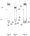
- FIG. 4 shows in principle the exemplary embodiment from FIG. 1 with the chip carrier 50 pushed in at the rear. the rear sealing end of the extraction piston 16 must be pushed somewhat inwards.
- FIG. 5 shows the exemplary embodiment shown in FIG. 2, the chip carrier 50 having the fitting 58, which has been turned over with respect to FIG. 4, being pushed into the open rear end of the sample container 20.
- FIG. 6 shows the exemplary embodiment shown in FIG. 3, the cap 60 being slipped over the rear end of the sample container 30, the chip carrier 50 being pushed rearwards to the bottom of the cap 60.
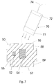
- FIG. 7 shows an enlarged exemplary embodiment of the chip carrier 50, which is drawn in a longitudinal section.
- the main body which can consist, for example, of plastic encapsulation or epoxy resin encapsulation, is designated by 55.
- a memory chip 52 is located in this encapsulation at a certain distance from the longitudinal axis, which is arranged in the form of a coil in the vicinity of a data transmission device 54 shown centrally in the axis.
- An external read / write device 70 is arranged above the chip carrier 50 on the right, with a front transmission part 71, which can be arranged at most about 5 cm from the chip carrier 50 during the contactless transmission process.
- the rear or internal transmission part 72 is connected via a cable 74 to a conventional computer which, based on a special application program, transmits the data received from the memory chip 52 via the coil 54 to the computer, where it can be displayed and processed.
- data can be entered into the computer via the computer keyboard and transmitted to the memory chip 52 via the read / write device 70 and the coil 54 within the chip carrier 50.
- a commercially available EEPROM chip is advantageously used as the memory chip 52.
- the front surface of the first fitting 58 is designated 56
- the second front surface of the opposite fitting 59 offset by 180 degrees and conically angled inwards, is 57.
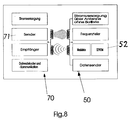
- FIG. 8 shows the example of a functional scheme for data transmission between chip carrier 50 or memory chip 52 in the form of an EEPROM and read / write device 70 or - not shown - computer.
- the chip carrier 50 or the memory chip 52 arranged there and the transmit / receive coil 54 do not have their own power supply. This is supplied via the external read / write device 70, which is connected to the computer, and can be, for example, approximately 140 kHz, 64 kHz or 128 kHz.
- a transmitting antenna and a receiving antenna are arranged on both the coil 54 and the transmitting part 71 of the read / write device 70.
- the data transmission takes place by modulation of this transmission frequency and certain customary circuit measures, which are not the subject of the invention. It should be mentioned that an internal power supply to the chip carrier with its own network connection would also be possible.
- the data are read out or read in and evaluated via an encoder and decoder.
- the sample container according to the invention enables a fixed captive attachment of all data to a sample container, the input via a conventional computer available in every doctor's office and a special handy read / write device, and the rapid, fully automatic evaluation of both personal data and work data by the commissioned laboratory doctor and, if necessary Linking this data with the measured values determined.
- the chip carrier is denoted by 36, it also represents the actuating piston which can be displaced in the direction of the arrow within the sample container 34 made of glass, plastic or the like in order to remove the sample and possibly remove it again.
- the memory chip 52 and the data transmission device 54 are integrated in this actuating piston 36, preferably cast in a sealing manner.
- the piston is provided with an actuating rod 38, at the end of which the actuating lever 39 is attached. After the sample container has been filled, the actuating lever 38 can be broken off in a known manner at the predetermined breaking point 41 for shipping. The sample is then removed after removal of the cover 35 provided on the opposite side of the tube 34.
- a test tube 44 with a lid 45 attached is provided as the sample container.
- the chip carrier 46 is cast in or embedded in a sealing manner on its bottom, which is usually rounded.
- the memory chip 52 and the data transmission device 54 are provided in the chip carrier 46, preferably cast in tightly.
- the chip carrier can preferably consist of epoxy resin.
- FIG. 11 shows a sample container tube 64 which is open on both sides and which is therefore particularly cheap.
- the chip carrier 66 is inserted at one end and connected to the tube 64 in a sealing manner.
- the chip chip 66 and the data transmission device 54 are provided in the chip carrier 66 and are electrically connected to one another.
- the data transmission device 54 transmits the signals to the reader / writer via an antenna or receives data from it.
- FIG. 12 shows a reader / writer 70 with the essential sub-modules.
- the centerpiece is a microprocessor 102, which is operated via a keyboard 100 and a driver 104.
- a line strand leads from the microprocessor 102 to the EPROM 106 and to the EEPROM 108, a further line leads to a modulator 114, which modulates the fundamental frequency of the microprocessor 102 in accordance with data to be transmitted and supplies it to the transmitting / receiving antenna 118 via an RF driver 116.
- data received by the antenna 118 is fed to the demodulator 112, which forwards the data to the microprocessor 102 for further processing and, if appropriate, storage.
- a monitoring element 110 is provided for circuit monitoring.
- the antenna 218 of the data transmission device 54 is arranged, which is electrically connected to the memory chip 52.
- a first type of data that is transmitted from the read / write device to the memory chip 52 of the sample container is designated by 122 and serves to supply energy
- a second type of data that is transmitted both from the read / write device 70 to the memory chip 52 and in FIG can be transmitted in the opposite direction is designated by 124 and serves to transmit data between reader / writer 70 and memory chip 52.
- the antenna 218 of the data transmission device 54 on the sample container ie generally on the chip carrier, is connected on the one hand to a rectifier to which a voltage control 206 and a reset voltage 204 are fed.
- the antenna 218 is connected to a clock 208, a modulator 212 for data to be transmitted and a demodulator 210 for received data.
- This antenna preferably consists of a copper coil.
- Centerpiece of the memory chip is an EEPROM 216 and a communication circuit 214 connected thereto.
Abstract
Description
Die Erfindung bezieht sich auf einen Probebehälter gemäß dem Oberbegriff des Anspruches 1.The invention relates to a sample container according to the preamble of claim 1.
Derartige Probenbehälter dienen insbesondere dazu, von Patienten der Ärzte Blut, Urin und dergl. aufzunehmen, zu verschließen und in ein Speziallabor zur Untersuchung zu übersenden. Bisher ist es üblich, sowohl die Personendaten als auch die Informationen über die durchzuführenden Untersuchungen in einem Beiblatt der Probe mitzugeben. Dies ist zeitraubend und umständlich und beinhaltet die Gefahr von Verwechselungen, insbesondere hinsichtlich der Personendaten. Daher geht man in letzter Zeit verstärkt dazu über, die Personendaten über ein sogenanntes Strichcodegerät auf ein entsprechendes Etikett einzulesen und auf den Probenbehälter, in aller Regel Glas, aufzukleben. Beim untersuchenden Laborarzt wird dann das fest mit dem Probenbehälter verbundene Personendaten-Etikett über einen ähnlichen oder gleichen Strichcodeleser in einen Computer eingelesen. Anschließend werden die Arbeitsdaten, d.h. die Informationen über die durchzuführenden Untersuchungen, per Hand von dem nach wie vor erforderlichen beigefügten Datenblatt in den Computer eingelesen. Diese Arbeit ist verhältnismäßig umständlich, darüber hinaus kann es nach wie vor zu Verwechselungen über die durchzuführenden Arbeiten kommen, wenn verschiedene Datenblätter vertauscht werden.Specimen containers of this type are used in particular to take blood, urine and the like from patients of the doctors, to seal them and to send them to a special laboratory for examination. So far, it has been common to include both the personal data and the information about the examinations to be carried out in a supplementary sheet of the sample. This is time-consuming and cumbersome and involves the risk of confusion, especially with regard to personal data. For this reason, there has recently been an increasing tendency to read the personal data on a corresponding label using a so-called bar code device and to stick it on the sample container, usually glass. At the examining laboratory doctor, the personal data label that is firmly connected to the sample container is then read into a computer using a similar or identical bar code reader. Then the working data, i.e. the information about the examinations to be carried out is read into the computer by hand from the data sheet that is still required. This work is relatively cumbersome, in addition, there can still be confusion about the work to be carried out if different data sheets are exchanged.
Der Erfindung liegt die Aufgabe zugrunde, einen Probenbehälter gemäß dem Oberbegriff des Anspruches 1 so auszugestalten, daß eine automatische Eingabe der Daten über einen Computer ermöglicht wird, und daß wenigstens Identifizier- Daten stets fest mit dem Probenbehälter verbunden sind.The invention has for its object to design a sample container according to the preamble of claim 1 so that an automatic input of the data is made possible via a computer, and that at least identification data are always permanently connected to the sample container.
Die Aufgabe wird erfindungsgemäß durch einen Probenbehälter mit den Merkmalen des Anspruches 1 gelöst. Weitere Ausgestaltungen der Erfindung sind in den Unteransprüchen unter Schutz gestellt.The object is achieved by a sample container with the features of claim 1. Further embodiments of the invention are protected in the subclaims.
Beim Erfindungsgegenstand wird als einziger Datenträger ein Speicherchip vorgesehen, der über eine Daten- Übertragungseinrichtung mit Hilfe eines Lesegerätes oder eines Schreib- /Lesegerätes abtastbar ist, das mit einem Computer verbunden ist. Speicherchip und Übertragungseinrichtung sind an einem Chipträger angeordnet, der mit dem Probenbehälter fest oder lösbar verbunden ist. Die Verbindung kann durch ein Paßstück erfolgen, das in ein offenes Ende des Probenbehälters einschiebbar ist, oder über eine Kappe, in welche der Chipträger eingelegt wird, und welche dann über das Ende des Probenbehälters passend und festsitzend aufgeschoben wird.In the subject matter of the invention, the only data carrier provided is a memory chip which can be scanned via a data transmission device with the aid of a reading device or a read / write device which is connected to a computer. The memory chip and the transmission device are arranged on a chip carrier, which is fixedly or detachably connected to the sample container. The connection can be made by a fitting that can be inserted into an open end of the sample container, or by a cap, into which the chip carrier is inserted, and which is then pushed over the end of the sample container in a fitting and tight manner.
Als offenes Ende des Probenbehälters dient in aller Regel dasjenige Ende, das der Entnahmenadel für die Probe gegenüber liegt und in welchem der abdichtende Ansaugstempel oder Ansaugkolben für das Einfüllen von Blut oder Urin und dergl. unter Unterdruck angeordnet ist. Das hintere Ende dieses Entnahmestempels kann entfernt oder abgebrochen werden, der Stempel selbst kann unter Umständen bei Bedarf etwas nach innen geschoben werden, damit das Paßstück des Chipträgers in das hintere offene Ende des Probenbehälters eingeschoben werden kann.The open end of the sample container is usually the end opposite the removal needle for the sample and in which the sealing suction plunger or suction piston for the filling of blood or urine and the like is arranged under negative pressure. The rear end of this removal stamp can be removed or broken off, the stamp itself can, if necessary, be pushed somewhat inwards so that the adapter of the chip carrier can be inserted into the rear open end of the sample container.
Am gleichen Chipträger können mehrere verschiedene Paßstücke für unterschiedliche Innendurchmesser von Probenbehältern vorgesehen werden. Als Speicherchip wird zweckmäßigerweise ein sogenanntes EEPROM eingesetzt, das im Handel frei erhältlich ist und das frei programmierbar ist, d.h. daß Daten beliebig gespeichert und wieder ausgelesen werden können. Zur Übertragung der gespeicherten Daten sowie zum Einlesen der Daten zu Speicherzwecken kann eine spezielle elektromagnetische Spule dienen, die entweder selbst als Antenne fungiert oder mit einer entsprechenden Antenne zusammenwirkt, so daß ein Lesegerät oder ein Schreib- Lesegerät in Form eines induktiven Lesegerätes berührungslos bei einer Entfernung von weniger als etwa 5 cm vom Chipträger die Daten einlesen und auslesen kann.Several different adapters for different inner diameters of sample containers can be provided on the same chip carrier. A so-called EEPROM is expediently used as the memory chip, which is freely available commercially and which is freely programmable, that is to say that data can be stored as desired and read again. A special electromagnetic coil, which itself serves as an antenna, can be used to transmit the stored data and to read in the data for storage purposes acts or cooperates with a corresponding antenna, so that a reader or a write-reader in the form of an inductive reader can contact and read the data at a distance of less than about 5 cm from the chip carrier.
Als Material für den Chipträger kann verschiedener elektrisch isolierender Kunststoff eingesetzt werden, beispielsweise Epoxid-Harzverguß. Die Kappe kann aus elastischem Kunststoff oder aus Gummi bestehen.Various electrically insulating plastics can be used as the material for the chip carrier, for example epoxy resin potting. The cap can be made of elastic plastic or rubber.
Der Chipträger für den Speicherchip und die mit diesem elektrisch verbundene Daten- Übertragungseinrichtung kann auch in den Betätigungskolben des Probenbehälters integriert werden, beispielsweise in diesem vergossen werden. Hierbei kann der Chipträger auch identisch mit dem Betätigungskolben sein. Verwendet man einen Probenbehälter in Form eines einfachen Reagenzglases mit einem offenen, über einen Verschlußstopfen verschließbaren Ende und einem geschlossenen, häufig abgerundeten Ende, so kann man den Speicherchip nebst Daten- Übertragungseinrichtung auch am Boden dieses Reagenzglases anordnen, entweder gegenüber dem Inhalt abgedichtet oder in einem eingegossenen Chipträger. Weiterhin kann man auch ein einfaches zylindrisches Rohr als Probenbehälter benutzen, in dessen einem offenen Ende der Chipträger mit integriertem, beispielsweise eingegossenem, Speicherchip und Daten-Übertragunseinrichtung abdichtend eingeschoben wird.The chip carrier for the memory chip and the data transmission device electrically connected to it can also be integrated in the actuating piston of the sample container, for example cast in it. Here, the chip carrier can also be identical to the actuating piston. If you use a sample container in the form of a simple test tube with an open end that can be closed by means of a stopper and a closed, often rounded end, the memory chip and data transmission device can also be arranged on the bottom of this test tube, either sealed against the contents or in one molded chip carrier. Furthermore, one can also use a simple cylindrical tube as a sample container, in the open end of which the chip carrier with an integrated, for example cast-in, memory chip and data transmission device is inserted in a sealing manner.
Der Speicherchip kann beispielsweise ein EEPROM sein, die Daten-Übertragungseinrichtung eine elektromagnetische Spule, es kann ein induktives reines Lese gerät oder kombiniertes Schreib- /Lesegerät eingesetzt werden. Beim Programmieren oder der Dateneingabe wird an die elektromagnetische Spule des Speicherchips ein entsprechend den Daten moduliertes Wechselstromsignal über eine entsprechende elektromagnetische Sendespule des Lesegerätes oder Schreib- /Lesegerätes gesendet. Umgekehrt wird beim Lesen ein nicht moduliertes Wechselstromsignal gesendet und ein moduliertes Wechselstromsignal empfangen. Das Programmieren bzw. die Dateneingabe und das Lesen efolgen vorzugsweise über eine Computer- Tastatur des Schreib- /Lesegerätes.The memory chip can be, for example, an EEPROM, the data transmission device an electromagnetic coil, an inductive read-only device or a combined read / write device can be used. During programming or data input, an alternating current signal modulated in accordance with the data is sent to the electromagnetic coil of the memory chip via a corresponding electromagnetic transmitter coil of the reading device or writing / reading device. Conversely, a non-modulated reading AC signal sent and received a modulated AC signal. Programming or data entry and reading are preferably carried out via a computer keyboard of the read / write device.
Im einzelnen kann ein Schreib- /Lesegerät als Basis einen Mikroprozessor aufweisen, der über einen Treiber betätigt wird und Daten über ein EPROM sowie ein E²PROM bzw. EEPROM empfängt, speichert und abgibt. Weiterhin sind ein Modulator, ein Demodulator und ein Überwachungsglied sowie eine Antenne vorgesehen, desgleichen natürlich eine Energieversorgung.In particular, a read / write device can have a microprocessor as the base, which is actuated by a driver and receives, stores and outputs data via an EPROM and an E²PROM or EEPROM. Furthermore, a modulator, a demodulator and a monitoring element as well as an antenna are provided, as is, of course, an energy supply.
Die Energieversorgung des Speicherchips erfolgt über das Lesegerät oder das Schreib- /Lesegerät und die gleiche Sendeantenne desselben zur entsprechenden Antenne des Speicherchips in Form der Daten-Übertragunseinrichtung. Beide Antennen können aus induktiven elektromagnetischen Spulen, wie Kupferspulen, bestehen.The energy supply of the memory chip takes place via the reader or the read / write device and the same transmitting antenna of the same to the corresponding antenna of the memory chip in the form of the data transmission device. Both antennas can consist of inductive electromagnetic coils, such as copper coils.
Der Speicherchip kann außer einem Gleichrichter, einem Spannungsregler und einem Spannungs- Rücksteller einen Taktgeber, einen Modulator, einen Demodulator, ein EEPROM und einen Kommunikations- Schaltkreis enthalten.In addition to a rectifier, a voltage regulator and a voltage restorer, the memory chip can contain a clock, a modulator, a demodulator, an EEPROM and a communication circuit.
Ausführungsbeispiele der Erfindung sind in der Zeichnung dargestellt.Embodiments of the invention are shown in the drawing.
Es zeigt:
- Fig. 1
- einen Probenbehälter und einen noch nicht eingeführten Chipträger,
- Fig. 2
- einen anderen kleineren Probenbehälter mit nicht eingeführtem Chipträger,
- Fig. 3
- einen weiteren Probenbehälter und eine dahinter angeordnete Kappe, in welche ein Chipträger eingepaßt ist,
- Fig. 4
- den Probenbehälter gemäß Figur 1 mit eingesetztem Chipträger,
- Fig. 5
- den Probenbehälter gemäß Figur 2 mit eingesetztem Chipträger,
- Fig. 6
- den Probenbehälter gemäß Figur 3 mit aufgestülpter Kappe,
- Fig. 7
- einen Chipträger in stark vergrößerter Darstellung mit darin eingesetzem Speicherchip, benachbart hierzu angeordneter Daten-Übertragungseinrichtung sowie einem berührungslosen Schreib-/Lesegerät,
- Fig. 8
- ein Funktionsschema für die Datenübertragung,
- Fig. 9
- einen Probenbehälter, bei dem der Mikrochip und die benachbarte, elektrisch damit verbundene Daten- Übertragungseinrichtung im Betätigungskolben enthalten ist,
- Fig. 10
- einen Probenbehälter in Form eines Reagenzglases, an dessen Boden der Chipträger mit Speicherchip und Daten-Übertragungseinrichtung eingegossen ist,
- Fig. 11
- einen Probenbehälter in Form eines an beiden Seiten offenen Röhrchens, wobei an einem Ende der Chipträger mit Speicherchip und Daten- Übertragungseinrichtung eingegossen bzw. abdichtend eingeschoben ist,
- Fig. 12
- ein Lese- /Schreibgerät zum Lesen, Programmieren und Eingeben von Daten in Form eines Schaltschemas,
- Fig. 13
- den Speicherchip mit damit verbundener Daten- Übertragungseinrichtung, der mit dem Probenbehälter verbunden ist, in Form eines Schaltschemas.
- Fig. 1
- a sample container and a not yet inserted chip carrier,
- Fig. 2
- another smaller sample container with the chip carrier not inserted,
- Fig. 3
- another sample container and a cap arranged behind it, into which a chip carrier is fitted,
- Fig. 4
- 1 with the chip carrier inserted,
- Fig. 5
- 2 the sample container according to FIG. 2 with the chip carrier inserted,
- Fig. 6
- 3 the sample container according to FIG. 3 with the cap attached,
- Fig. 7
- a chip carrier in a greatly enlarged representation with a memory chip inserted therein, a data transmission device arranged adjacent to it and a contactless read / write device,
- Fig. 8
- a functional diagram for data transmission,
- Fig. 9
- a sample container in which the microchip and the adjacent, electrically connected data transmission device are contained in the actuating piston,
- Fig. 10
- a sample container in the form of a test tube, on the bottom of which the chip carrier with memory chip and data transmission device is cast,
- Fig. 11
- a sample container in the form of a tube open on both sides, with the chip carrier with memory chip and data transmission device being cast in or inserted in a sealing manner at one end,
- Fig. 12
- a reader / writer for reading, programming and entering data in the form of a circuit diagram,
- Fig. 13
- the memory chip with the associated data transmission device, which is connected to the sample container, in the form of a circuit diagram.
In Figur 1 ist der Probenbehälter, hier in Form eines Kunststoff- oder Glasröhrchens, allgemein mit 10 bezeichnet, an seinem oberen Ende weist er ein Röhrchen 12 auf, auf welches eine sterile Entnahmenadel oder dergleichen aufgesetzt werden kann, welche die Probe, beispielsweise Blut, entweder direkt aus der Vene der Untersuchungsperson aufnimmt, oder welche die Probe aus einem anderen Behälter in den zylindrischen Innenraum des Probenbehälters hineinsaugt. Diesem Zweck dient ein Entnahmekolben 16, der bei seinem Herausziehen nach hinten einen Unterdruck innerhalb des Probenbehälters erzeugt. Hinter dem Probenbehälter 10 ist ein Chipträger 50 angeordnet, der in Pfeilrichtung in das hintere offene Ende 14 des Probenbehälters 10 einschiebbar ist, wobei gleichzeitig der Entnahmekolben oder Entnahmestempel 16, welcher hinten abgebrochen ist oder von welchem der Ziehgriff entfernt wurde, in Pfeilrichtung nach innen eingeschoben wird. Es sei erwähnt, daß die Abdichtung als solche jeweils durch den Entnahmekolben bzw. Entnahmestempel 16 hergestellt wird, so daß es nur darauf ankommt, durch einen entsprechenden Paßsitz eine feste mechanische Klemmverbindung oder andere Verbindung mit dem Probenbehälter 10 herzustellen, damit der Speicherchip 50 stets mit dem Probenbehälter sicher verbunden bleibt.In Figure 1 is the sample container, here in the form of a plastic or Glass tube, generally designated 10, at its upper end it has a
Figur 2 zeigt ein anderes Ausführungsbeispiel für einen Probenbehälter 20 mit geringerem Durchmesser, vorderem Entnahmeröhrchen 22, hinteren abgebrochenen Entnahmekolben 26 und hinteren offenen Ende 24. Im Vergleich zur Darstellung von Figur 1 ist der Chipträger 50 bei Figur 2 um 180 Grad gedreht, so daß das entgegengesetzte Ende des Chipträgers 50, das als Paßstück 58 mit gegenüber dem Außenumfang des Chipträgers 50 kleinerem Durchmesser ausgebildet ist, dem offenen Ende 24 des Probenbehälters 20 zugewandt ist. Das entgegengesetzte Paßstück 59 mit kleinerem Durchmesser als das erste Paßstück, entsprechend dem Probenbehälter von Figur 1, ist dabei dem Probenbehälter abgewandt.FIG. 2 shows another embodiment for a
Figur 3 zeigt ein weiteres Ausführungsbeispiel der Erfindung, bei dem der Chipträger 50 in eine Kappe 60 eingepaßt ist. Wird die Kappe 60 in Pfeilrichtung auf das hintere Ende 24 gegenüber dem Probeentnahmeröhrchen 32 auf den Probenbehälter 30 aufgeschoben, so kann der Chipträger 50 innerhalb der Kappe 60 nach hinten in eine Vertiefung geschoben werden, welche dem hinteren Paßsitz 59 entsprechen kann. Bei diesem Ausführungsbeispiel kann das hintere Ende 24 des Probenbehälters 30 auch geschlossen sein und beispielsweise nur eine einzige vordere Einfüllöffnung im Bereich des Proberöhrchens 32 aufweisen, das auch durch einen einfachen Stöpsel ersetzt sein kann.FIG. 3 shows a further exemplary embodiment of the invention, in which the
Figur 4 zeigt im Prinzip das Ausführungsbeispiel von Figur 1 mit hinten eingeschobenem Chipträger 50, wobei u.U. das hintere abdichtende Ende des Entnahmekolbens 16 etwas nach innen geschoben werden muß.FIG. 4 shows in principle the exemplary embodiment from FIG. 1 with the
Figur 5 zeigt das in Figur 2 dargestellte Ausführungsbeispiel, wobei der Chipträger 50 mit - gegenüber Figur 4 umgedrehtem - Paßstück 58 in das offene hintere Ende des Probenbehälters 20 eingeschoben ist.FIG. 5 shows the exemplary embodiment shown in FIG. 2, the
Figur 6 zeigt das in Figur 3 dargestellte Ausführungsbeispiel, wobei die Kappe 60 über das hintere Ende des Probenbehälters 30 gestülpt ist, wobei der Chipträger 50 nach hinten bis zum Boden der Kappe 60 geschoben ist.FIG. 6 shows the exemplary embodiment shown in FIG. 3, the
Figur 7 zeigt ein vergrößertes Ausführungsbeispiel des Chipträgers 50, der in Längsschnitt-Darstellung gezeichnet ist. Der Hauptkörper, der beispielsweise aus Kunststoffverguß oder Epoxid-Harzverguß bestehen kann, wird mit 55 bezeichnet. In diesen Verguß ist in einem gewissen Abstand zur Längsachse ein Speicherchip 52 eingezeichnet, der in der Nähe einer in der Achse zentral eingezeichneten Daten-Übertragungseinrichtung 54 in Form einer Spule angeordnet ist.FIG. 7 shows an enlarged exemplary embodiment of the
Oberhalb des Chipträgers 50 rechts ist ein externes Schreib-/Lesegerät 70 angeordnet mit einem vorderen Übertragungsteil 71, das beim berührungslosen Übertragungsvorgang maximal etwa 5 cm vom Chipträger 50 angeordnet sein kann. Das hintere oder interne Übertragungsteil 72 ist über ein Kabel 74 mit einem übliche Computer verbunden, der aufgrund eines speziellen Anwendungsprogrammes vom Speicherchip 52 über die Spule 54 die erhaltenen Daten an den Computer überträgt, wo sie angezeigt und verarbeitet werden können. Umgekehrt können Daten über die Computertastatur in den Computer eingegeben und über das Schreib-/Lesegerät 70 und die Spule 54 innerhalb des Chipträgers 50 an den Speicherchip 52 übertragen werden. Als Speicherchip 52 wird vorteilhaft ein handelsüblicher EEPROM-Chip eingesetzt. In Figur 7 ist im übrigen neu die Vorderfläche des ersten Paßstückes 58 mit 56, die zweite, um 180 Grad versetzte und nach innen kegelförmig abgewinkelte Vorderfläche des entgegengesetzten Paßstückes 59 mit 57 bezeichnet.An external read /
Figur 8 zeigt das Beispiel eines Funktionsschemas für die Datenübertragung zwischen Chipträger 50 bzw. Speicherchip 52 in Form eines EEPROM's und Schreib-/Lesegerät 70 bzw. - nicht dargestelltem - Computer. Der Chipträger 50 bzw. dort angeordnete Speicherchip 52 und die Sende/Empfangs-Spule 54 hat keine eigene Stromversorgung. Diese wird über das externe Schreib-/Lesegerät 70, das mit dem Computer verbunden ist, zugeführt, sie kann beispielsweise etwa 140 KHz, 64 KHz bzw. 128 KHz betragen. Sowohl an der Spule 54 als auch am Sendeteil 71 des Schreib-/Lesegerätes 70 sind jeweils eine Sendeantenne und eine Empfangsantenne angeordnet. Die Datenübertragung erfolgt durch Modulation dieser Sendesfrequenz und bestimmte schaltungsmäßige übliche Maßnahmen, die nicht Gegenstand der Erfindung sind. Erwähnt sei, daß auch eine interne Stromversorgung des Chipträgers mit eigenem Netzanschluß möglich wäre. Die Daten werden über einen Codierer und Decodierer ausgelesen bzw. eingelesen und ausgewertet.FIG. 8 shows the example of a functional scheme for data transmission between
Der erfindungsgemäße Probenbehälter ermöglicht eine feste unverlierbare Anbringung sämtlicher Daten an einem Probenbehälter, die Eingabe über einen üblichen, in jeder Arztpraxis vorhandenen Computer und ein spezielles handliches Schreib-/ Lesegerät und die rasche vollautomatische Auswertung sowohl der Personendaten als auch der Arbeitsdaten beim beauftragten Laborarzt und ggf. das Verknüpfen dieser Daten mit den festgestellten Meßwerten.The sample container according to the invention enables a fixed captive attachment of all data to a sample container, the input via a conventional computer available in every doctor's office and a special handy read / write device, and the rapid, fully automatic evaluation of both personal data and work data by the commissioned laboratory doctor and, if necessary Linking this data with the measured values determined.
Im Probenbehälter gemäß Fig. 9 ist der Chipträger mit 36 bezeichnet, er stellt gleichzeitig den Betätigungskolben dar, der in Pfeilrichtung innerhalb des Probebehälters 34 aus Glas, Kunststoff oder dergleichen verschiebbar ist, um die Probe zu entnehmen und unter Umständen wieder zu entfernen. In diesem Betätigungskolben 36 ist der Speicherchip 52 sowie die Daten- Übertragungseinrichtung 54 integriert, vorzugsweise abdichtend eingegossen. Nach außen ist der Kolben mit einer Betätigungsstange 38 versehen, an deren Ende der Betätigungshebel 39 angebracht ist Nach dem Befüllen des Probenbehälters kann der Betätigungshebel 38 in bekannter Weise an der Sollbruchstelle 41 für den Versand abgebrochen werden. Die Entnahme der Probe erfolgt dann nach Entfernung des an der gegenüberliegenden Seite des Röhrchens 34 vorgesehenen Deckels 35.In the sample container according to FIG. 9, the chip carrier is denoted by 36, it also represents the actuating piston which can be displaced in the direction of the arrow within the
Im Ausführungsbeispiel von Fig. 10 ist als Probenbehälter ein Reagenzglas 44 mit aufgesetztem Deckel 45 vorgesehen. An dessen, üblicherweise abgerundetem, Boden ist der Chipträger 46 eingegossen oder abdichtend eingelassen. Im Chipträger 46 ist der Speicherchip 52 sowie die Daten- Übertragungseinrichtung 54 vorgesehen, vorzugsweise dicht eingegossen. Auch in diesem Falle kann der Chipträger vorzugsweise aus Epoxydharz bestehen.In the exemplary embodiment in FIG. 10, a
Fig. 11 zeigt ein an beiden Seiten offenes Probenbehälter- Röhrchen 64, das somit besonders billig ist. An einem Ende ist der Chipträger 66 eingeschoben und mit dem Röhrchen 64 abdichtend verbunden. Im Chipträger 66 ist wiederum der Speicherchip 52 sowie die Daten- Übertragungseinrichtung 54 vorgesehen, welche miteinander elektrisch verbunden sind. Hierbei überträgt die Daten-Übertragungseinrichtung 54 über eine Antenne die Signale zum Lese- /Schreibgerät oder empfängt von diesem Daten.11 shows a
Das Schaltschema von Fig. 12 zeigt ein Lese- /Schreibgerät 70 mit den wesentlichen Untermodulen. Kernstück bildet ein Mikroprozessor 102, der über eine Tastatur 100 und einen Treiber 104 betätigt wird. Vom Mikroprozessor 102 führt ein Leitungsstrang zum EPROM 106 und zum EEPROM 108, eine weitere Leitung führt zu einem Modulator 114, der die Grundfrequenz des Mikroprozessors 102 entsprechend zu sendenden Daten moduliert und über einen RF-Treiber 116 der Sende- /Empfangsantenne 118 zuführt. Andererseits werden von der Antenne 118 empfangene Daten dem Demodulator 112 zugeführt, welcher die Daten zur weiteren Verarbeitung und gegebenenfalls Speicherung an den Mikroprozessor 102 weitergibt.The circuit diagram of FIG. 12 shows a reader /
Zur Schaltungsüberwachung ist ein Überwachungsglied 110 vorgesehen.A
Neben das Lese- /Schreibgerät 70 ist die Antenne 218 der Daten-Übertragungseinrichtung 54 angeordnet, die elektrisch mit dem Speicherchip 52 verbunden ist. Eine erste Art von Daten, die vom Lese- /Schreibgerät zum Speicherchip 52 des Probenbehälters übertragen werden, ist mit 122 bezeichnet und dient der Energiezufuhr, eine zweite Art von Daten, die sowohl vom Lese- /Schreibgerät 70 zum Speicherchip 52, als auch in umgekehrter Richtung übertragen werden können, ist mit 124 bezeichnet und dient der Übertragung von Daten zwischen Lese- /Schreibgerät 70 und Speicherchip 52.In addition to the reader /
Die Antenne 218 der Daten- Übertragungseinrichtung 54 am Probenbehälter, d.h. in der Regel am Chipträger, ist einerseits mit einem Gleichrichter verbunden, dem eine Spannungsregelung 206 sowie eine Rückstellspannung 204 zugeführt wird. Andererseits ist die Antenne 218 mit einem Taktgeber 208, einem Modulator 212 für zu sendende Daten und einem Demodulator 210 für empfangene Daten verbunden. Diese Antenne besteht vorzugsweise aus einer Kupferspule. Kernstück des Speicherchips ist ein EEPROM 216 und ein damit verbundener Kommunikations- Schaltkreis 214.The
Claims (11)
dadurch gekennzeichnet,
characterized,
oder daß der Chipträger (50) in eine Kappe (60) paßt, die festsitzend auf ein offenes oder geschlossenes Ende (24) des Probenbehälters (30) aufschiebbar ist.Sample container according to claim 2, characterized in that the chip carrier (50) has at least one adapter (58; 59) which fits into an open end (14; 24) of the sample container (10; 20) is firmly inserted,
or that the chip carrier (50) fits into a cap (60) which can be pushed tightly onto an open or closed end (24) of the sample container (30).
Applications Claiming Priority (2)
| Application Number | Priority Date | Filing Date | Title |
|---|---|---|---|
| DE9416270U | 1994-10-10 | ||
| DE9416270U DE9416270U1 (en) | 1994-10-10 | 1994-10-10 | Laboratory sample container |
Publications (1)
| Publication Number | Publication Date |
|---|---|
| EP0706825A1 true EP0706825A1 (en) | 1996-04-17 |
Family
ID=6914681
Family Applications (1)
| Application Number | Title | Priority Date | Filing Date |
|---|---|---|---|
| EP95115832A Withdrawn EP0706825A1 (en) | 1994-10-10 | 1995-10-07 | Sample holder for blood, urine or the like, having data carrier |
Country Status (3)
| Country | Link |
|---|---|
| EP (1) | EP0706825A1 (en) |
| JP (1) | JPH08211065A (en) |
| DE (1) | DE9416270U1 (en) |
Cited By (32)
| Publication number | Priority date | Publication date | Assignee | Title |
|---|---|---|---|---|
| WO1999003585A1 (en) * | 1997-07-16 | 1999-01-28 | Clids Oy | Specimen tube |
| DE19740429A1 (en) * | 1997-09-11 | 1999-03-25 | Genom Analytik Gmbh | Device for withdrawing biological sample |
| WO1999056696A1 (en) * | 1998-05-06 | 1999-11-11 | Dominique Lambert | Bag with radio frequency reading/writing label for collecting, storing and transporting blood or blood components |
| EP1003577A1 (en) * | 1997-07-25 | 2000-05-31 | Bristol-Myers Squibb Company | Blood product delivery system |
| WO2000033959A1 (en) * | 1998-12-09 | 2000-06-15 | Central Labo Europe (S.A.R.L.) | Biological analysis system comprising means controlling the pairing between a biological analysis equipment and a matching container receptacle |
| FR2796182A1 (en) * | 1999-07-05 | 2001-01-12 | Lab Med Blutbank Technologie G | Data transmission between data chip attached to blood bag and computer chip of weighing device, avoiding all risk of error |
| FR2803226A1 (en) * | 1999-12-06 | 2001-07-06 | Greiner Bio One Gmbh | DEVICE AND METHOD RELATING TO A CONTAINER AND ITS SEALING |
| DE10010140A1 (en) * | 2000-03-03 | 2001-09-13 | Leica Microsystems | Automatic system processing e.g. histological and cytological preparations, comprises slides with code identifying them and determining their handling and treatment |
| EP1136087A2 (en) * | 2000-03-10 | 2001-09-26 | LMB Technologie GmbH | Device and method for monitoring and managing products |
| GB2362464A (en) * | 2000-05-17 | 2001-11-21 | Markes Int Ltd | Sampling tube having a transponder |
| WO2002009020A2 (en) * | 2000-07-21 | 2002-01-31 | Patram (Patent And Trademark Administration) Limited | Method for handling an article |
| WO2002040708A2 (en) * | 2000-11-20 | 2002-05-23 | Siemens Aktiengesellschaft | Method for the retention of information data for the application of a biochip/sample support |
| EP1210979A1 (en) * | 2000-11-29 | 2002-06-05 | Advanced Biotechnologies Limited | Sample tubes with fluid tight label chambers |
| WO2002045777A1 (en) * | 2000-12-08 | 2002-06-13 | L.M.B. (Lab Med Blutbank) Technologie Gmbh | Device for transmitting data between an electronic chip associated with a blood bag and the computer device of a weighing system |
| US6475443B1 (en) * | 1997-04-28 | 2002-11-05 | Sgt Exploitatie B.V. | Device for storing and/or treating chemicals |
| WO2002046719A3 (en) * | 2000-12-07 | 2002-12-19 | Fraunhofer Ges Forschung | Cryostorage method and device |
| DE19758633C2 (en) * | 1997-09-11 | 2003-10-23 | Biopsytec Gmbh | Device for taking biological samples |
| FR2861702A1 (en) * | 2003-10-30 | 2005-05-06 | Cybernetix | Flask for holding a biological sample comprises cap enclosing color-coded identification and electronic label with memory and contact-less emitter |
| WO2005109332A1 (en) * | 2004-05-12 | 2005-11-17 | Ivf Limited | Identification of cryo-preserved samples |
| DE102004024960A1 (en) * | 2004-05-21 | 2005-12-15 | Bruker Daltonik Gmbh | Vessel for the cultivation of microbe colonies, from a primary sample of blood or urine, has an electronic label for remote machine writing/reading to store identity data |
| FR2923164A1 (en) * | 2007-11-05 | 2009-05-08 | Raymond Et Cie Soc En Commandi | ANALYSIS TEST |
| DE102012202197B3 (en) * | 2012-02-14 | 2013-04-18 | Siemens Aktiengesellschaft | Blood collection tube with integrated sensor device |
| FR2985590A1 (en) * | 2012-01-10 | 2013-07-12 | Dreampath Diagnostics | DEVICE AND METHOD FOR STORING AND ORDERING BIOLOGICAL SAMPLING CASSETTES |
| WO2014114938A2 (en) * | 2013-01-23 | 2014-07-31 | Cryogatt Systems Limited | Rfid tag |
| US8900856B2 (en) | 2004-04-08 | 2014-12-02 | Biomatrica, Inc. | Integration of sample storage and sample management for life science |
| US9376709B2 (en) | 2010-07-26 | 2016-06-28 | Biomatrica, Inc. | Compositions for stabilizing DNA and RNA in blood and other biological samples during shipping and storage at ambient temperatures |
| US9725703B2 (en) | 2012-12-20 | 2017-08-08 | Biomatrica, Inc. | Formulations and methods for stabilizing PCR reagents |
| US10064404B2 (en) | 2014-06-10 | 2018-09-04 | Biomatrica, Inc. | Stabilization of thrombocytes at ambient temperatures |
| US10568317B2 (en) | 2015-12-08 | 2020-02-25 | Biomatrica, Inc. | Reduction of erythrocyte sedimentation rate |
| US10973226B2 (en) | 2018-10-05 | 2021-04-13 | TMRW Life Sciences, Inc. | Apparatus to preserve and identify biological samples at cryogenic conditions |
| USD951481S1 (en) | 2020-09-01 | 2022-05-10 | TMRW Life Sciences, Inc. | Cryogenic vial |
| USD963194S1 (en) | 2020-12-09 | 2022-09-06 | TMRW Life Sciences, Inc. | Cryogenic vial carrier |
Families Citing this family (30)
| Publication number | Priority date | Publication date | Assignee | Title |
|---|---|---|---|---|
| US6340588B1 (en) | 1995-04-25 | 2002-01-22 | Discovery Partners International, Inc. | Matrices with memories |
| US6329139B1 (en) | 1995-04-25 | 2001-12-11 | Discovery Partners International | Automated sorting system for matrices with memory |
| US5751629A (en) | 1995-04-25 | 1998-05-12 | Irori | Remotely programmable matrices with memories |
| CN1181720A (en) * | 1995-04-25 | 1998-05-13 | 伊萝莉公司 | Remotely programmable matrices with memories and uses thereof |
| US6416714B1 (en) | 1995-04-25 | 2002-07-09 | Discovery Partners International, Inc. | Remotely programmable matrices with memories |
| US6331273B1 (en) | 1995-04-25 | 2001-12-18 | Discovery Partners International | Remotely programmable matrices with memories |
| US6352854B1 (en) | 1995-04-25 | 2002-03-05 | Discovery Partners International, Inc. | Remotely programmable matrices with memories |
| US5961923A (en) * | 1995-04-25 | 1999-10-05 | Irori | Matrices with memories and uses thereof |
| US6017496A (en) | 1995-06-07 | 2000-01-25 | Irori | Matrices with memories and uses thereof |
| US5741462A (en) | 1995-04-25 | 1998-04-21 | Irori | Remotely programmable matrices with memories |
| US5925562A (en) * | 1995-04-25 | 1999-07-20 | Irori | Remotely programmable matrices with memories |
| US6319668B1 (en) | 1995-04-25 | 2001-11-20 | Discovery Partners International | Method for tagging and screening molecules |
| US5874214A (en) | 1995-04-25 | 1999-02-23 | Irori | Remotely programmable matrices with memories |
| DE19540527A1 (en) * | 1995-10-31 | 1997-05-07 | Hewlett Packard Gmbh | Identification modules for exchangeable components in analytical instruments |
| DE19621179C2 (en) * | 1996-05-25 | 2000-09-07 | Nonnenmacher Klaus | Transport unit for samples |
| DE19849591C2 (en) * | 1997-10-27 | 2001-07-19 | Hitachi Ltd | Automatic analyzer |
| DE19838232A1 (en) * | 1998-08-22 | 2000-03-02 | Knoell Hans Forschung Ev | Micro chip card stores data for a large number of samples to work with a computer through an interface with a large memory and data security |
| DE19841554A1 (en) * | 1998-09-11 | 2000-03-23 | Biochip Technologies Gmbh | Carrier unit for liquid or solid samples has a unique coding and/or memory with a stored identity code for effective archiving without additional manual manipulation |
| JP2002042078A (en) * | 2000-07-21 | 2002-02-08 | Leading Information Technology Institute | Electronic tag device |
| FR2825638B1 (en) * | 2001-10-18 | 2003-09-12 | Biolog | METHOD FOR DETERMINING AND MONITORING THE AGING OF BLOOD BAGS IN BLOOD TRANSFUSION ESTABLISHMENTS AND CARE ESTABLISHMENTS |
| JP4168091B2 (en) * | 2002-05-27 | 2008-10-22 | 吉秀 西川 | Mini tube |
| JP4024619B2 (en) * | 2002-08-09 | 2007-12-19 | 株式会社日立製作所 | Information reading device for semiconductor devices |
| DE10251132A1 (en) * | 2002-10-28 | 2004-05-13 | Apibio Sas | Biochip is formed from a continuous solid carrier, fitted with an array of electrodes, a unique identification zone and a transceiver system for chemical and biochemical tests/reactions |
| JP2006153524A (en) * | 2004-11-25 | 2006-06-15 | Kobe Bio Robotix Kk | Housing and operation system of miniature tube assembly |
| EP1980976A4 (en) | 2006-01-05 | 2010-03-24 | Hitachi Chemical Co Ltd | Tubular container enabling individual identification |
| JP5506168B2 (en) * | 2008-08-04 | 2014-05-28 | 村角工業株式会社 | Sample container |
| JP2011059093A (en) * | 2009-09-10 | 2011-03-24 | Genesis Corp | Blood collecting tube with tag and blood collecting operation supporting system |
| JP5545727B2 (en) * | 2010-04-01 | 2014-07-09 | 日立マクセル株式会社 | Microtube, and IC chip sealing method in microtube |
| US9845489B2 (en) | 2010-07-26 | 2017-12-19 | Biomatrica, Inc. | Compositions for stabilizing DNA, RNA and proteins in saliva and other biological samples during shipping and storage at ambient temperatures |
| FR3010818B1 (en) * | 2013-09-17 | 2016-12-09 | Dreampath Diagnostics | METHOD FOR DETECTING THE POSITION OF A CASSETTE AND ITS DEVICE |
Citations (3)
| Publication number | Priority date | Publication date | Assignee | Title |
|---|---|---|---|---|
| FR2555744A1 (en) * | 1983-11-30 | 1985-05-31 | Philips Ind Commerciale | Test piece with means for storing the results of analysis |
| WO1989008264A1 (en) * | 1988-03-04 | 1989-09-08 | Ballies Uwe W | Process for automatic, fully selective analysis of blood or its constituents |
| DE4306563A1 (en) * | 1993-03-03 | 1994-09-08 | Jan Lichtenberg | Specimen container for specimens to be analysed |
Family Cites Families (10)
| Publication number | Priority date | Publication date | Assignee | Title |
|---|---|---|---|---|
| DE2733074A1 (en) * | 1977-07-19 | 1979-02-01 | Klauske Juergen | Identification station for clinical specimens - has machine-coded labels read by processor-controlled heads attached to conveyor assembly |
| DE3518531A1 (en) * | 1985-05-23 | 1986-11-27 | Dieter Dipl.-Phys. Dr. 8500 Nürnberg Hafner | Device for the storage and time-prompted taking of medicaments |
| DE3721822C1 (en) * | 1987-07-02 | 1988-11-10 | Philips Patentverwaltung | Chip card |
| US5077476A (en) * | 1990-06-27 | 1991-12-31 | Futrex, Inc. | Instrument for non-invasive measurement of blood glucose |
| FR2685519A1 (en) * | 1991-12-20 | 1993-06-25 | Gemplus Card Int | SYSTEM FOR THE IDENTIFICATION OF CONTAINERS, ESPECIALLY GAS BOTTLES. |
| DE4215956C2 (en) * | 1992-05-14 | 1994-04-28 | Siemens Ag | Information transmission system consisting of a read / write unit and a portable data carrier arrangement |
| AT400647B (en) * | 1992-05-20 | 1996-02-26 | Neutron Electronic Computer Gm | CARD WITH A MAGNETIC STRIP |
| AU4626893A (en) * | 1992-09-14 | 1994-03-24 | Aprex Corporation | Contactless communication system |
| DE4242112A1 (en) * | 1992-12-15 | 1994-06-16 | Eurosil Electronic Gmbh | Control for a switched load of an IC card |
| DE4243108A1 (en) * | 1992-12-18 | 1994-06-23 | Eurosil Electronic Gmbh | IC card |
-
1994
- 1994-10-10 DE DE9416270U patent/DE9416270U1/en not_active Expired - Lifetime
-
1995
- 1995-10-07 EP EP95115832A patent/EP0706825A1/en not_active Withdrawn
- 1995-10-11 JP JP7263062A patent/JPH08211065A/en active Pending
Patent Citations (3)
| Publication number | Priority date | Publication date | Assignee | Title |
|---|---|---|---|---|
| FR2555744A1 (en) * | 1983-11-30 | 1985-05-31 | Philips Ind Commerciale | Test piece with means for storing the results of analysis |
| WO1989008264A1 (en) * | 1988-03-04 | 1989-09-08 | Ballies Uwe W | Process for automatic, fully selective analysis of blood or its constituents |
| DE4306563A1 (en) * | 1993-03-03 | 1994-09-08 | Jan Lichtenberg | Specimen container for specimens to be analysed |
Cited By (64)
| Publication number | Priority date | Publication date | Assignee | Title |
|---|---|---|---|---|
| US6475443B1 (en) * | 1997-04-28 | 2002-11-05 | Sgt Exploitatie B.V. | Device for storing and/or treating chemicals |
| US6733731B2 (en) | 1997-04-28 | 2004-05-11 | Sgt Exploitatie B.V. | Device for storing and/or treating chemicals |
| US7097812B2 (en) | 1997-04-28 | 2006-08-29 | Sgt Exploitatie B.V. | Device for storing and/or treating chemicals |
| WO1999003585A1 (en) * | 1997-07-16 | 1999-01-28 | Clids Oy | Specimen tube |
| EP1003577A1 (en) * | 1997-07-25 | 2000-05-31 | Bristol-Myers Squibb Company | Blood product delivery system |
| EP1003577A4 (en) * | 1997-07-25 | 2001-02-14 | Bristol Myers Squibb Co | Blood product delivery system |
| DE19740429A1 (en) * | 1997-09-11 | 1999-03-25 | Genom Analytik Gmbh | Device for withdrawing biological sample |
| DE19740429C2 (en) * | 1997-09-11 | 2002-03-14 | Biopsytec Gmbh | Procedure for taking biological samples |
| DE19758633C2 (en) * | 1997-09-11 | 2003-10-23 | Biopsytec Gmbh | Device for taking biological samples |
| DE19758619C2 (en) * | 1997-09-11 | 2003-12-18 | Biopsytec Gmbh | Device for sampling and labeling a living being |
| FR2778335A1 (en) * | 1998-05-06 | 1999-11-12 | Dominique Lambert | RADIO FREQUENCY READ / WRITE LABEL POCKET FOR COLLECTION, STORAGE AND TRANSPORT OF BLOOD OR BLOOD COMPONENTS |
| WO1999056696A1 (en) * | 1998-05-06 | 1999-11-11 | Dominique Lambert | Bag with radio frequency reading/writing label for collecting, storing and transporting blood or blood components |
| FR2787042A1 (en) * | 1998-12-09 | 2000-06-16 | Central Labo Europ | BIOLOGICAL ANALYSIS SYSTEM INCLUDING A MEANS OF CHECKING THE MATCH BETWEEN BIOLOGICAL ANALYSIS EQUIPMENT AND A COMPLEMENTARY CONTAINER. |
| WO2000033959A1 (en) * | 1998-12-09 | 2000-06-15 | Central Labo Europe (S.A.R.L.) | Biological analysis system comprising means controlling the pairing between a biological analysis equipment and a matching container receptacle |
| FR2796182A1 (en) * | 1999-07-05 | 2001-01-12 | Lab Med Blutbank Technologie G | Data transmission between data chip attached to blood bag and computer chip of weighing device, avoiding all risk of error |
| FR2803226A1 (en) * | 1999-12-06 | 2001-07-06 | Greiner Bio One Gmbh | DEVICE AND METHOD RELATING TO A CONTAINER AND ITS SEALING |
| NL1016782C2 (en) * | 1999-12-06 | 2002-09-10 | Greiner Bio One Gmbh | Device in the form of a reservoir and / or closure. |
| BE1014015A3 (en) * | 1999-12-06 | 2003-02-04 | Greiner Bio One Gmbh | DEVICE AND METHOD RELATING TO A CONTAINER AND ITS CLOSURE. |
| DE10010140A1 (en) * | 2000-03-03 | 2001-09-13 | Leica Microsystems | Automatic system processing e.g. histological and cytological preparations, comprises slides with code identifying them and determining their handling and treatment |
| EP1136087A2 (en) * | 2000-03-10 | 2001-09-26 | LMB Technologie GmbH | Device and method for monitoring and managing products |
| EP1136087A3 (en) * | 2000-03-10 | 2003-07-30 | LMB Technologie GmbH | Device and method for monitoring and managing products |
| GB2362464A (en) * | 2000-05-17 | 2001-11-21 | Markes Int Ltd | Sampling tube having a transponder |
| WO2002009020A2 (en) * | 2000-07-21 | 2002-01-31 | Patram (Patent And Trademark Administration) Limited | Method for handling an article |
| WO2002009020A3 (en) * | 2000-07-21 | 2002-09-19 | Patram Patent And Trademark Ad | Method for handling an article |
| WO2002040708A3 (en) * | 2000-11-20 | 2004-02-26 | Siemens Ag | Method for the retention of information data for the application of a biochip/sample support |
| WO2002040708A2 (en) * | 2000-11-20 | 2002-05-23 | Siemens Aktiengesellschaft | Method for the retention of information data for the application of a biochip/sample support |
| EP1210979A1 (en) * | 2000-11-29 | 2002-06-05 | Advanced Biotechnologies Limited | Sample tubes with fluid tight label chambers |
| US6884397B2 (en) | 2000-11-29 | 2005-04-26 | Advanced Biotechnologies Limited | Sample tubes with fluid-tight labels |
| WO2002046719A3 (en) * | 2000-12-07 | 2002-12-19 | Fraunhofer Ges Forschung | Cryostorage method and device |
| US6931864B2 (en) | 2000-12-07 | 2005-08-23 | Fraunhofer-Gesellschaft zur Förderung der angewandten Forschung e.V. | Cryostorage method and device |
| CN1585894B (en) * | 2000-12-07 | 2010-08-04 | 弗劳恩霍弗应用技术研究院 | Cryostorage method and device |
| EP2302351A1 (en) * | 2000-12-07 | 2011-03-30 | Fraunhofer-Gesellschaft zur Förderung der angewandten Forschung e.V. | Method and apparatus for cryogenic storage of probes |
| WO2002045777A1 (en) * | 2000-12-08 | 2002-06-13 | L.M.B. (Lab Med Blutbank) Technologie Gmbh | Device for transmitting data between an electronic chip associated with a blood bag and the computer device of a weighing system |
| FR2861702A1 (en) * | 2003-10-30 | 2005-05-06 | Cybernetix | Flask for holding a biological sample comprises cap enclosing color-coded identification and electronic label with memory and contact-less emitter |
| US9078426B2 (en) | 2004-04-08 | 2015-07-14 | Biomatrica, Inc. | Integration of sample storage and sample management for life science |
| US8900856B2 (en) | 2004-04-08 | 2014-12-02 | Biomatrica, Inc. | Integration of sample storage and sample management for life science |
| WO2005109332A1 (en) * | 2004-05-12 | 2005-11-17 | Ivf Limited | Identification of cryo-preserved samples |
| EP2315163A1 (en) * | 2004-05-12 | 2011-04-27 | Research Instruments Limited | Identification of cryo-preserved samples |
| DE102004024960A1 (en) * | 2004-05-21 | 2005-12-15 | Bruker Daltonik Gmbh | Vessel for the cultivation of microbe colonies, from a primary sample of blood or urine, has an electronic label for remote machine writing/reading to store identity data |
| WO2009059687A1 (en) * | 2007-11-05 | 2009-05-14 | A. Raymond Et Cie | Analysis sampling tube |
| FR2923164A1 (en) * | 2007-11-05 | 2009-05-08 | Raymond Et Cie Soc En Commandi | ANALYSIS TEST |
| US9999217B2 (en) | 2010-07-26 | 2018-06-19 | Biomatrica, Inc. | Compositions for stabilizing DNA, RNA, and proteins in blood and other biological samples during shipping and storage at ambient temperatures |
| US9376709B2 (en) | 2010-07-26 | 2016-06-28 | Biomatrica, Inc. | Compositions for stabilizing DNA and RNA in blood and other biological samples during shipping and storage at ambient temperatures |
| FR2985590A1 (en) * | 2012-01-10 | 2013-07-12 | Dreampath Diagnostics | DEVICE AND METHOD FOR STORING AND ORDERING BIOLOGICAL SAMPLING CASSETTES |
| WO2013104865A1 (en) | 2012-01-10 | 2013-07-18 | Dreampath Diagnostics | Device and method for storing and ordering biological sampling blocks |
| US9260243B2 (en) | 2012-01-10 | 2016-02-16 | Dreampath Diagnostics | Device and method for storing and ordering biological sampling blocks |
| DE102012202197B3 (en) * | 2012-02-14 | 2013-04-18 | Siemens Aktiengesellschaft | Blood collection tube with integrated sensor device |
| US9468404B2 (en) | 2012-02-14 | 2016-10-18 | Siemens Aktiengesellschaft | Blood sampling tube with integrated sensor device |
| US9725703B2 (en) | 2012-12-20 | 2017-08-08 | Biomatrica, Inc. | Formulations and methods for stabilizing PCR reagents |
| US9501734B2 (en) | 2013-01-23 | 2016-11-22 | Cryogatt Systems Limited | RFID tag |
| US9697457B2 (en) | 2013-01-23 | 2017-07-04 | Cryogatt Systems Limited | RFID tag |
| WO2014114938A3 (en) * | 2013-01-23 | 2014-11-20 | Cryogatt Systems Limited | Rfid tag |
| EP3287192A1 (en) * | 2013-01-23 | 2018-02-28 | Cryogatt Systems Limited | Rfid tag |
| WO2014114938A2 (en) * | 2013-01-23 | 2014-07-31 | Cryogatt Systems Limited | Rfid tag |
| US10772319B2 (en) | 2014-06-10 | 2020-09-15 | Biomatrica, Inc. | Stabilization of thrombocytes at ambient temperatures |
| US10064404B2 (en) | 2014-06-10 | 2018-09-04 | Biomatrica, Inc. | Stabilization of thrombocytes at ambient temperatures |
| US11672247B2 (en) | 2014-06-10 | 2023-06-13 | Biomatrica, Inc. | Stabilization of thrombocytes at ambient temperatures |
| US10568317B2 (en) | 2015-12-08 | 2020-02-25 | Biomatrica, Inc. | Reduction of erythrocyte sedimentation rate |
| US11116205B2 (en) | 2015-12-08 | 2021-09-14 | Biomatrica, Inc. | Reduction of erythrocyte sedimentation rate |
| US10973226B2 (en) | 2018-10-05 | 2021-04-13 | TMRW Life Sciences, Inc. | Apparatus to preserve and identify biological samples at cryogenic conditions |
| US11252956B2 (en) | 2018-10-05 | 2022-02-22 | TMRW Life Sciences, Inc. | Apparatus to preserve and identify biological samples at cryogenic conditions |
| USD951481S1 (en) | 2020-09-01 | 2022-05-10 | TMRW Life Sciences, Inc. | Cryogenic vial |
| USD963194S1 (en) | 2020-12-09 | 2022-09-06 | TMRW Life Sciences, Inc. | Cryogenic vial carrier |
| USD1002868S1 (en) | 2020-12-09 | 2023-10-24 | TMRW Life Sciences, Inc. | Cryogenic vial carrier |
Also Published As
| Publication number | Publication date |
|---|---|
| JPH08211065A (en) | 1996-08-20 |
| DE9416270U1 (en) | 1994-12-08 |
Similar Documents
| Publication | Publication Date | Title |
|---|---|---|
| EP0706825A1 (en) | Sample holder for blood, urine or the like, having data carrier | |
| EP2219543B1 (en) | Device for contactless communication | |
| EP1972269B1 (en) | System for in vivo measurement of an analyte concentration | |
| WO2011144355A1 (en) | Medical treatment arrangement | |
| WO1989008264A1 (en) | Process for automatic, fully selective analysis of blood or its constituents | |
| EP2168485A1 (en) | Breast holder for examination device for examination of breasts | |
| WO2006069675A1 (en) | Measuring system for the measurement of material concentrations in liquid media | |
| DE10154843A1 (en) | Method and device for labeling slides for microtomized tissue samples and their processing | |
| EP1819275A1 (en) | Sample tube for receiving body fluids, particularly blood | |
| WO2002078431A2 (en) | Animal ear tag pliers | |
| DE10014542A1 (en) | System for detecting and locating surgical instruments and materials used during operations, requires use of a non-removable identification device for each element of set of surgical instruments and materials | |
| DE2733074C3 (en) | ||
| EP1988394A1 (en) | Measuring system with distributed functions | |
| EP2492015B1 (en) | Sample container, system and analysis method | |
| DE69930408T2 (en) | PROCESS FOR BIOLOGICAL ANALYSIS WITH A MEANS FOR TRANSMITTING IDENTIFICATION SAFETY BETWEEN A DEVICE AND AN ASSOCIATED TANK | |
| EP2948058B1 (en) | Hand-held measuring device | |
| EP3560592A2 (en) | Laboratory centrifuge, centrifuge tubes for a laboratory centrifuge and method for operating a centrifuge container | |
| DE202006003578U1 (en) | container | |
| DE4440250A1 (en) | Physical, chemical and biological sample parameter measuring device | |
| DE102006027008A1 (en) | Animal`s e.g. cow, liquid sample e.g. milk, receiving container for use in sample taking device, has identification unit, extending over part of periphery of container, comprising base body made from partially transparent material | |
| WO2018011241A1 (en) | Dental or dental-surgical treatment device for recognising dental tissue and/or an anomaly on the dental tissue | |
| DE602004010245T2 (en) | Wireless communication of physiological variables | |
| EP0736288A2 (en) | Hose identification | |
| DE202004017909U1 (en) | Device for the electronic detection of dimensions, in particular body dimensions of a patient | |
| DE102004018558A1 (en) | Method and device for detecting functional states in RFID or remote sensor systems |
Legal Events
| Date | Code | Title | Description |
|---|---|---|---|
| PUAI | Public reference made under article 153(3) epc to a published international application that has entered the european phase |
Free format text: ORIGINAL CODE: 0009012 |
|
| AK | Designated contracting states |
Kind code of ref document: A1 Designated state(s): DE FR IT |
|
| STAA | Information on the status of an ep patent application or granted ep patent |
Free format text: STATUS: THE APPLICATION IS DEEMED TO BE WITHDRAWN |
|
| 18D | Application deemed to be withdrawn |
Effective date: 19961119 |