EP0706832B1 - Air operated paint spray gun - Google Patents
Air operated paint spray gun Download PDFInfo
- Publication number
- EP0706832B1 EP0706832B1 EP94116197A EP94116197A EP0706832B1 EP 0706832 B1 EP0706832 B1 EP 0706832B1 EP 94116197 A EP94116197 A EP 94116197A EP 94116197 A EP94116197 A EP 94116197A EP 0706832 B1 EP0706832 B1 EP 0706832B1
- Authority
- EP
- European Patent Office
- Prior art keywords
- supply line
- compressed air
- paint spray
- spray gun
- plug
- Prior art date
- Legal status (The legal status is an assumption and is not a legal conclusion. Google has not performed a legal analysis and makes no representation as to the accuracy of the status listed.)
- Expired - Lifetime
Links
Images


Classifications
-
- B—PERFORMING OPERATIONS; TRANSPORTING
- B05—SPRAYING OR ATOMISING IN GENERAL; APPLYING FLUENT MATERIALS TO SURFACES, IN GENERAL
- B05B—SPRAYING APPARATUS; ATOMISING APPARATUS; NOZZLES
- B05B7/00—Spraying apparatus for discharge of liquids or other fluent materials from two or more sources, e.g. of liquid and air, of powder and gas
- B05B7/02—Spray pistols; Apparatus for discharge
- B05B7/08—Spray pistols; Apparatus for discharge with separate outlet orifices, e.g. to form parallel jets, i.e. the axis of the jets being parallel, to form intersecting jets, i.e. the axis of the jets converging but not necessarily intersecting at a point
- B05B7/0807—Spray pistols; Apparatus for discharge with separate outlet orifices, e.g. to form parallel jets, i.e. the axis of the jets being parallel, to form intersecting jets, i.e. the axis of the jets converging but not necessarily intersecting at a point to form intersecting jets
- B05B7/0815—Spray pistols; Apparatus for discharge with separate outlet orifices, e.g. to form parallel jets, i.e. the axis of the jets being parallel, to form intersecting jets, i.e. the axis of the jets converging but not necessarily intersecting at a point to form intersecting jets with at least one gas jet intersecting a jet constituted by a liquid or a mixture containing a liquid for controlling the shape of the latter
- B05B7/0838—Spray pistols; Apparatus for discharge with separate outlet orifices, e.g. to form parallel jets, i.e. the axis of the jets being parallel, to form intersecting jets, i.e. the axis of the jets converging but not necessarily intersecting at a point to form intersecting jets with at least one gas jet intersecting a jet constituted by a liquid or a mixture containing a liquid for controlling the shape of the latter comprising a single means controlling simultaneously the flow rates of shaping and spraying gas jets
-
- B—PERFORMING OPERATIONS; TRANSPORTING
- B05—SPRAYING OR ATOMISING IN GENERAL; APPLYING FLUENT MATERIALS TO SURFACES, IN GENERAL
- B05B—SPRAYING APPARATUS; ATOMISING APPARATUS; NOZZLES
- B05B7/00—Spraying apparatus for discharge of liquids or other fluent materials from two or more sources, e.g. of liquid and air, of powder and gas
- B05B7/02—Spray pistols; Apparatus for discharge
- B05B7/08—Spray pistols; Apparatus for discharge with separate outlet orifices, e.g. to form parallel jets, i.e. the axis of the jets being parallel, to form intersecting jets, i.e. the axis of the jets converging but not necessarily intersecting at a point
- B05B7/0807—Spray pistols; Apparatus for discharge with separate outlet orifices, e.g. to form parallel jets, i.e. the axis of the jets being parallel, to form intersecting jets, i.e. the axis of the jets converging but not necessarily intersecting at a point to form intersecting jets
- B05B7/0815—Spray pistols; Apparatus for discharge with separate outlet orifices, e.g. to form parallel jets, i.e. the axis of the jets being parallel, to form intersecting jets, i.e. the axis of the jets converging but not necessarily intersecting at a point to form intersecting jets with at least one gas jet intersecting a jet constituted by a liquid or a mixture containing a liquid for controlling the shape of the latter
Abstract
Description
Die Erfindung betrifft eine druckluftbetriebene Farbspritzpistole nach dem Oberbegriff des Anspruchs 1 sowie einen Druckluftverteiler hierzu.The invention relates to a compressed air-operated paint spray gun according to the preamble of claim 1 and a compressed air distributor for this.
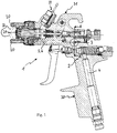
Eine gattungsgemäße, bekannte Farbspritzpistole 1 - wie sie in Figur 1 dargestellt
ist - besteht im wesentlichen aus einem einstückigen Gehäuse 2, welches einen Griffbereich
30 und einen Düsenbereich 31 aufweist. Über den Gehäusegriff 30 wird die
Farbspritzpistole 1 mit Druckluft versorgt. Auf die Oberseite der Farbspritzpistole
1 ist bei Fließbecherpistolen, wie dargestellt, ein Fließbecher an einem Anschluß 32
aufsetzbar, bei Hängebecherpistolen ist im Bereich der Düsenanordnung ein Hängebecher
an die Unterseite der Farbspritzpistole angeschraubt. Die der Farbspritzpistole
1 zugeführte Druckluft wird zu einem, die Farbaustrittsöffnung umgebenden,
Ringspalt 21 geführt und dort unter Druck ausgeblasen, wobei die Farbe durch das
entstehende Vakuum aus der Austrittsöffnung herausgesaugt, zerstäubt und mitgerissen
wird. Hierbei bildet sich ein im wesentlichen kegelförmiger Rundstrahl. Da
bei Lackierarbeiten jedoch häufig ein Flachstrahl bevorzugt wird, weisen die meisten
Farbspritzpistolen seitlich in Strahlrichtung zwei vorstehende Hörner 20 auf, welche
ebenfalls mit Druckluft beaufschlagt werden und deren Hornluftstrahlen 33 schräg
und gleichsinnig zur Abströmrichtung auf den Rundstrahl gerichtet sind und diesen
beidseitig deformieren. Der Grad dieser Deformierung kann durch Luftmenge und
Druck der Hornluft eingestellt werden, wozu die meisten bekannten Farbspritzpistolen
einen in Figur 1 nur schematisch dargestellten Druckluftverteiler 3 aufweisen,
an welchem die Druckluftzuleitung 4 in zwei Teilleitungen aufgezweigt wird. Ein
derartiger bekannter Druckluftverteiler ist in Figur 2 dargestellt. Eine der Teilleitungen,
die Rundstrahlversorgungsleitung 6 versorgt den genannten Ringspalt 21
mit Druckluft, die andere, die sogenannte Hornluftversorgungsleitung 5, versorgt die
Hörner 20 mit Druckluft. Zur Einstellung der Hornluft weisen die Druckluftverteiler
3 dieser bekannten Farbspritzpistolen 1 ein Einstellventil auf, bei dessen Betätigung
ein Küken 7 die abzweigende Hornluftversorgungsleitung 5 verschließt bzw. teilweise
oder ganz öffnet. Wenn dieses Ventil vollständig verschlossen ist, strömt keine Luft
aus den Hörnern 20 und es ergibt sich ein reiner Rundstrahl; je stärker dieses Ventil
geöffnet wird, desto stärker wird der Rundstrahl zu einem Flachstrahl verformt.A generic, known paint spray gun 1 - as shown in Figure 1
is - consists essentially of a one-
Diese bekannten Farbspritzpistolen haben den Nachteil, daß bei einem ganzen oder
teilweisen Verschließen der Hornluftversorgungsleitung 5 in Folge des konstanten
Drucks auf der Druckluftzuleitung 4 der Druck in der Rundstrahlversorgungsleitung
6 zunimmt. Die amerikanische Gesetzgebung schreibt in vielen Bundesstaaten jedoch
vor, daß Lacke nur mit Farbspritzpistolen verarbeitet werden dürfen, die einen
maximalen Düseninnendruck von 0,7 bar nicht überschreiten. Diese Art der Farbspritzpistolen
werden als nebelreduzierte oder HVLP (High Volume Low Pressure)
Pistolen bezeichnet. Der maßgebliche Druck der Hornluft wird hierbei in einem
Horn der Luftkappe, der Rundstrahldruck im Rundstrahlbereich gemessen. Um
eine optimale Farbauftragsqualität zu erhalten, muß die vorgegebene Grenze von
0,7 bar möglichst genau eingehalten werden, da die Lackierqualität mit abnehmendem
Druck sinkt. Beträgt also der Druck im Rundstrahlbereich bei eingeschalteter
Hornluft exakt 0,7 bar, so vergrößert er sich durch das Schließen der Hornluft auf
einen deutlich über 0,7 bar liegenden Wert, was nach der Gesetzgebung verboten
ist.These known paint spray guns have the disadvantage that a whole or
partial closure of the horn
Um diesen Nachteilen zu begegnen, wurde beispielsweise in der EP 381 072 A2 eine Niederdruckfarbspritzpistole vorgeschlagen, bei der eine Doppelkonusanordnung bewirkt, daß beim Verschließen der Hornluft auch die dem Ringspalt zugeführte Luftmenge verringert wird. Diese Doppelkonusanordnung eignet sich, baulich bedingt, jedoch nur für Hängebecherpistolen und nicht für Fließbecherpistolen, bei denen der Farbbecher oben aufgesetzt ist. Sie ist im übrigen nicht an vorhandene Pistolen nachrüstbar.In order to counter these disadvantages, for example, EP 381 072 A2 Low pressure paint spray gun proposed, in which a double cone arrangement causes that when closing the horn air also the amount of air supplied to the annular gap is reduced. This double cone arrangement is suitable for structural reasons however only for hanging cup guns and not for gravity cup guns where the Color cup is placed on top. Incidentally, it is not attached to existing pistols can be retrofitted.
Die US-A-5,090,623 bezieht sich auf eine Farbspritzpistole, bei welcher ebenfalls die dem Ringspalt zugeführte Luftmenge bei Reduzierung der Hornluftmenge reduziert wird. Die darin gezeigte Anordnung umfaßt eine gelochte Scheibe, welche die Luftkanäle in ihrem Verlauf voneinander trennt und welche verschiedene Bohrungen aufweist, die durch Verdrehen der Scheibe in die Luftkanäle eingebracht werden können. Die Anordnung ist jedoch sehr kompliziert und nach dem Zerlegen zur Reinigung der Farbspritzpistole kaum wieder zusammenzubauen. Außerdem ist sie ebenfalls nicht an vorhandene Farbspritzpistolen nachrüstbar.US-A-5,090,623 relates to a paint spray gun, which also the amount of air supplied to the annular gap is reduced when the amount of horn air is reduced becomes. The arrangement shown therein comprises a perforated disc which the Air channels separate in their course and what different holes has, which are introduced into the air channels by rotating the disc can. However, the arrangement is very complicated and after disassembly Hard to reassemble cleaning the paint spray gun. Besides, it is also cannot be retrofitted to existing paint spray guns.
Es besteht daher die Aufgabe, eine Farbspritzpistole so weiterzubilden, daß bei einfacher Ausführung der im Rundstrahlbereich auftretende Druck auf einen Maximalwert begrenzbar ist und welche nachträglich mit einer entsprechenden Druckbegrenzung ausgestattet werden kann.There is therefore the task of developing a paint spray gun so that at simple execution of the pressure occurring in the omnidirectional area to a maximum value can be limited and which can be retrospectively with a corresponding pressure limitation can be equipped.
Gelöst wird diese Aufgabe mit den kennzeichnenden Merkmalen des Anspruchs 1. Vorteilhafte Ausgestaltungen und ein Druckluftverteilereinsatz für eine derartige Farbspritzpistole sind den Unteransprüchen entnehmbar.This object is achieved with the characterizing features of claim 1. Advantageous configurations and a compressed air distributor insert for such Paint spray gun can be found in the subclaims.
Ein Ausführungsbeispiel der Erfindung wird im folgenden unter Bezugnahme auf die begleitenden Zeichnungen näher beschrieben, welche zeigen:
- Fig. 1
- einen Querschnitt durch eine Farbspritzpistole;
- Fig. 2
- einen Querschnitt durch einen in einer Farbspritzpistole eingebauten Druckluftverteiler nach dem Stand der Technik;
- Fig. 3
- einen Querschnitt durch den in der Farbspritzpistole eingebauten Druckluftverteiler entlang der Linie B - B aus Figur 1 bei geschlossener Hornluftversorgungsleitung;
- Fig. 4
- eine Darstellung gemäß
Figur 3 bei offener Hornluftversorgungsleitung; - Fig. 5
- einen Querschnitt durch den in der Farbspritzpistole eingebauten Druckluftverteiler entlang der Linie A - A aus Figur 1 bei geschlossener Hornluftversorgungsleitung; und
- Fig. 6
- eine Darstellung gemäß
Figur 5 bei offener Hornluftversorgungsleitung.
- Fig. 1
- a cross section through a paint spray gun;
- Fig. 2
- a cross section through a built-in a paint spray gun compressed air distributor according to the prior art;
- Fig. 3
- a cross section through the compressed air distributor installed in the paint spray gun along the line B - B of Figure 1 with the horn air supply line closed;
- Fig. 4
- a representation of Figure 3 with open horn air supply line;
- Fig. 5
- a cross section through the compressed air distributor installed in the paint spray gun along the line A - A of Figure 1 with the horn air supply line closed; and
- Fig. 6
- a representation according to Figure 5 with open horn air supply line.
In Figur 1 ist eine druckluftbetriebene Farbspritzpistole 1, wie sie sowohl dem Stand
der Technik entspricht als auch mit der vorliegenden Erfindung ausgestattet werden
kann, mit einem Gehäuse 2 dargestellt. Innerhalb des Pistolengriffs dieses Gehäuses
2 befindet sich eine Druckluftzuleitung 4, welche über eine Ventilanordnung zu einem
Druckluftverteiler 3 führt. In Figur 1 gestrichelt dargestellt sind die beiden
von diesem Druckluftverteiler 3 abgehenden Leitungen, nämlich die Hornluftversorgungsleitung,
welche die Hörner 20 mit Druckluft beaufschlagt und die Rundstrahlversorgungsleitung,
welche den die Farbdüse umgebenden Ringspalt 21 mit
Druckluft beaufschlagt.In Figure 1 is a compressed air-operated paint spray gun 1, as both the state
the technology corresponds as well as be equipped with the present invention
can, shown with a
Ein im Gehäuse 2 einer Farbspritzpistole 1 eingebauter Druckluftverteiler 3 nach
dem Stand der Technik ist in Figur 2 dargestellt, aus der auch die Rundstrahlversorgungsleitung
6 und die Hornluftversorgungsleitung 5 hervorgehen. Figur 2 entspricht
einem Schnitt entlang der Linie B - B aus Figur 1, sofern man unterstellt,
daß diese Farbspritzpistole nach dem Stand der Technik ausgebildet ist. Gemäß Figur
2 ist es bekannt, in einer seitlichen Öffnung des Gehäuses 2 der Farbspritzpistole
1 eine Gewindebohrung vorzusehen, in deren Innenbereich die Druckluftzuleitung 4,
die Rundstrahlversorgungsleitung 6 und die Hornluftversorgungsleitung 5 münden.
In diese Gehäusebohrung ist ein Druckluftverteilereinsatz eingeschraubt, welcher die
Anordnung zu einem Druckluftverteiler 3 ergänzt. Mit Hilfe eines außenliegenden
Rändelknopfes 14 dieses Einsatzes läßt sich ein Küken 7 senkrecht zur Wandung
des Gehäuses 2 verstellen, wodurch ein endständig an dem Küken 7 angebrachtes
Dichtzäpfchen 8 auf den Eingang der Hornluftversorgungsleitung 5 drückbar ist.
Da das Dichtzäpfchen 8 konisch ausgeführt ist, wird die Hornluftversorgungsleitung
5 somit abgedichtet. Dreht man den Rändelknopf 14 zurück, so wird die Hornluftversorgungsleitung
5 von dem Dichtzäpfchen 8 freigegeben und mit Hornluft
beaufschlagt. Dagegen wird die in Einschraubrichtung des Kükens 7 gesehen vor
der Hornluftversorgungsleitung 5 liegende Rundstrahlversorgungsleitung 6 immer,
das heißt unabhängig von der Stellung des Zäpfchens 7, mit Druckluft aus der (in
Figur 2 nicht dargestellten) Druckluftzuleitung 4 beaufschlagt. Beim Verschließen
der Hornluftversorgungsleitung 5 durch das Dichtzäpfchen 8 ergibt sich der in der
Beschreibungseinleitung erwähnte Effekt der Druckerhöhung in der Rundstrahlversorgungsleitung
6, gegebenenfalls über den zulässigen Maximalwert von 0,7 bar.A
In den Figuren 3 und 4 ist ein ähnlicher Schnitt wie in Figur 2, jedoch bei einer
erfindungsgemäßen Farbspritzpistole, dargestellt. Die Figuren 5 bzw. 6 entsprechen
den Figuren 3 bzw. 4, jedoch ist die Schnittdarstellung um 90° gedreht. Auf die Figuren
3 und 5, welche die Anordnung bei verschlossener Hornluftversorgungsleitung
5 zeigen und auf die Figuren 4 und 6, welche die Anordnung bei geöffneter Hornluftversorgungsleitung
5 zeigen, wird im folgenden gemeinsam Bezug genommen.In Figures 3 and 4 is a similar section as in Figure 2, but with one
Paint spray gun according to the invention shown. Figures 5 and 6 correspond
Figures 3 and 4, however, the sectional view is rotated by 90 °. On the figures
3 and 5, which the arrangement with closed horn
Im Unterschied zur Anordnung nach Figur 2 ist bei der erfindungsgemäßen Anordnung,
vom Ende des Kükens 7 her betrachtet, nach dem Dichtzäpfchen 8 ein Teller
9 größeren Durchmessers angeordnet. Der Durchmesser dieses Tellers ist nur geringfügig
kleiner als der Durchmesser des Außengewindes 12 des Druckluftverteilers
3. Der Teller 9 paßt sich somit etwa der Innenwandung der zylindrischen Bohrung
innerhalb des Gehäuses 2 an. Bei geöffneter Hornluftversorgungsleitung 5 (Figuren
4 und 6) beeinträchtigt der Teller 9 den Luftdurchgang von der Druckluftzuleitung 4
zu Rundstrahl- und Hornluftversorgungsleitungen 6 und 5 kaum oder gar nicht. Je
mehr die Hornluftversorgungsleitung 5 jedoch durch Eindrehen des Rändelknopfs 14,
und damit des Kükens 7 und des Dichtzäpfchens 8 geschlossen wird, umso mehr gelangt
der Teller 9 in den Bereich sowohl der Rundstrahlversorgungsleitung 6 als auch
der Druckluftzuleitung 4. Bei der in den Figuren 3 und 5 dargestellten, vollkommen
geschlossenen Stellung der Hornluftversorgungsleitung 5, blockiert der Teller 9 des
Zäpfchens 7 einen erheblichen Teil des Luftdurchgangs von der Druckluftzuleitung
4 zur Rundstrahlversorgungsleitung 6. Es ist von Bedeutung, daß der Teller 9 nicht
nur die Rundstrahlversorgungsleitung 6 an sich, sondern auch die Luftzuleitung 4
blockiert, da nur so der auf beide Leitungen 5 und 6 zu verteilende Gesamtdruck
begrenzbar ist.In contrast to the arrangement according to FIG. 2, in the arrangement according to the invention,
viewed from the end of
Der in der Rundstrahlversorgungsleitung 6 zu erreichende Maximaldruck kann durch
geeignete Wahl der Abmessungen des Tellers 9 eingestellt werden. Insbesondere
können die Höhe und der Durchmesser des Tellers 9 zur Anpassung variiert werden.
Je größer der Spalt zwischen dem Teller 9 und der Rundstrahlversorgungsleitung 6
ist, umso geringer ist die Drosselwirkung bei Verstellung der Regulierung bezüglich
des Rundstrahles. Das gleiche gilt für die Höhe des Tellers 9 bzw. die daran angebrachte
Anfasung. Über die Höhe des Dichtzäpfchens 8 bzw. über den Dichtkonus
am Teller 9 kann die Hornluftmenge bzw. die Feinheit der Verstellung des Luftdrucks
bzw. der Luftmenge variiert werden.The maximum pressure to be achieved in the
Damit die Farbspritzpistole optimal arbeitet, muß darauf geachtet werden, daß das
Gewinde im Körper der Pistole nicht in den Bereich der Rundstrahlversorgungsleitung
6 hineinreicht, da ansonsten Druckverluste über das Gewinde entstehen können.
Desweiteren muß der Durchmesser der Bohrung relativ genau ausgeführt werden.In order for the paint spray gun to work optimally, care must be taken that the
Thread in the body of the gun is not in the area of the
In einer vorteilhaften Ausgestaltung der Erfindung sind das Dichtzäpfchen 8 und
der Teller 9 einstückig gefertigt und weisen ein Innengewinde 10 zum Aufschrauben
auf einen, den Kern des Kükens 7 bildenden Gewindestift 11 auf. Alternativ hierzu
kann der Teller 9 auch auf ein Küken 7, wie es in Figur 2 dargestellt ist, aufgesetzt
werden.In an advantageous embodiment of the invention, the sealing
Da die Erfindung es ermöglicht, eine Druckluftverteilereinheit in eine vorhandene
Farbspritzpistole nachzurüsten, ist Gegenstand der Erfindung auch eine Druckluftverteilereinheit
an sich, wobei unter dem Begriff der Druckluftverteilereinheit nur
die aus Küken 7, Teller 9, Dichtzäpfchen 8 und Rändelknopf 14 gefertigte Baueinheit
zu verstehen ist, welche über das Außengewinde 12 in das Gehäuse 2 der Farbspritzpistole
1 einschraubbar ist. Aus dieser Baueinheit wird erst im Zusammenwirken
mit den Bohrungen 4, 5 und 6 innerhalb des Gehäuses 2 ein Druckluftverteiler.Since the invention enables an air distribution unit to be installed in an existing one
Retrofitting paint spray gun, the subject of the invention is also a compressed air distribution unit
per se, only under the term compressed air distribution unit
the assembly made from
Claims (7)
- A paint spray gun (1) operated by compressed air, with a housing (2) which exhibits a compressed air distributor (3) which is connected to a compressed air supply line (4) and distributes the compressed air frog it to a horn air supply line (5) and a round jet supply line (6), where the amount of compressed air fed to the horn air supply line may be set through screw adjustment of a plug (7), the sealing tip (8) at the end of which at the same time continuously opens or closes the born air supply line (5), characterized in that
the plug (7) as seen from the end exhibits beyond the sealing tip (8) a region of larger diameter made as a plate like a washer, which upon the born air supply line (5) being closed also continuously constricts the airway between the compressed air supply line (4) and the round jet supply line (6), whereby the pressure in the round jet supply line (6) is limited to a predetermined maximum value. - A paint spray gun (1) as in Claim 1 or 2, characterized in that the predetermined maximum value amounts to 0.7 bar.
- A paint spray gun (1) as in one of the preceding Claims,
characterized in that upon actuation of the plug (7) the plate (9) acts both upon the compressed air supply line (4) and upon the round jet supply line (6). - A paint spray gun (1) as in one of the preceding Claims,
characterized in that the sealing tip (8) and plate (9) are manufactured in one piece and exhibit an internal thread (10) for screwing onto a threaded pin (11) forming the core of the plug (7). - A paint spray gun (1) as in one of the preceding Claims,
characterized in that its housing (2) exhibits a bore of which the outside carries a non-continuous inner thread into which the compressed air distributor (3) may be screwed via an outer thread (12). - A paint spray gun (1) as in one of the preceding Claims,
characterized in that the plug (7) is connected to turn with a knurled knob (14) fitted outside the housing. - A compressed air distributor insert for a paint spray gun (1) as in Claim 5 or 6, having an outer thread (12) for screwing into the paint spray gun (1) and a plug (7) which is adjustable axially via a knurled knob (14) and has a sealing tip (8) at the end of it,
characterized in that
as seen from the end of the plug (7) a region of larger diameter made as a plate (9) is arranged beyond the sealing tip (8).
Priority Applications (4)
| Application Number | Priority Date | Filing Date | Title |
|---|---|---|---|
| EP94116197A EP0706832B1 (en) | 1994-10-13 | 1994-10-13 | Air operated paint spray gun |
| ES94116197T ES2115840T3 (en) | 1994-10-13 | 1994-10-13 | COMPRESSED AIR ACTUATED SPRAY GUN. |
| DE59405399T DE59405399D1 (en) | 1994-10-13 | 1994-10-13 | Air-operated paint spray gun |
| AT94116197T ATE163577T1 (en) | 1994-10-13 | 1994-10-13 | COMPRESSED AIR POWERED PAINT SPRAY GUN |
Applications Claiming Priority (1)
| Application Number | Priority Date | Filing Date | Title |
|---|---|---|---|
| EP94116197A EP0706832B1 (en) | 1994-10-13 | 1994-10-13 | Air operated paint spray gun |
Publications (2)
| Publication Number | Publication Date |
|---|---|
| EP0706832A1 EP0706832A1 (en) | 1996-04-17 |
| EP0706832B1 true EP0706832B1 (en) | 1998-03-04 |
Family
ID=8216381
Family Applications (1)
| Application Number | Title | Priority Date | Filing Date |
|---|---|---|---|
| EP94116197A Expired - Lifetime EP0706832B1 (en) | 1994-10-13 | 1994-10-13 | Air operated paint spray gun |
Country Status (4)
| Country | Link |
|---|---|
| EP (1) | EP0706832B1 (en) |
| AT (1) | ATE163577T1 (en) |
| DE (1) | DE59405399D1 (en) |
| ES (1) | ES2115840T3 (en) |
Cited By (14)
| Publication number | Priority date | Publication date | Assignee | Title |
|---|---|---|---|---|
| DE202009009406U1 (en) | 2009-07-08 | 2010-11-25 | Sata Gmbh & Co. Kg | Spray Gun |
| DE102009032399A1 (en) | 2009-07-08 | 2011-01-13 | Sata Gmbh & Co. Kg | Spray Gun |
| DE202011003941U1 (en) | 2011-03-14 | 2011-08-19 | Sata Gmbh & Co. Kg | Spray Gun |
| DE202012003116U1 (en) | 2012-03-28 | 2012-05-10 | Sata Gmbh & Co. Kg | Spray gun and associated compressed air distributor insert |
| US8925836B2 (en) | 2008-10-29 | 2015-01-06 | Sata Gmbh & Co. Kg | Gravity cup for a paint sprayer |
| CN104368468A (en) * | 2013-08-14 | 2015-02-25 | 浙江奥利达气动工具股份有限公司 | Amplitude stepless adjusting device and spray gun with same |
| USD740393S1 (en) | 2013-09-27 | 2015-10-06 | Sata Gmbh & Co. Kg | Paint spray gun |
| US9327301B2 (en) | 2008-03-12 | 2016-05-03 | Jeffrey D. Fox | Disposable spray gun cartridge |
| USD758537S1 (en) | 2014-07-31 | 2016-06-07 | Sata Gmbh & Co. Kg | Paint spray gun rear portion |
| US9409197B2 (en) | 2013-12-18 | 2016-08-09 | Sata Gmbh & Co. Kg | Air nozzle closure for a spray gun |
| USD768820S1 (en) | 2014-09-03 | 2016-10-11 | Sata Gmbh & Co. Kg | Paint spray gun with pattern |
| USD770593S1 (en) | 2014-07-31 | 2016-11-01 | Sata Gmbh & Co. Kg | Paint spray gun |
| EP3421138A1 (en) | 2017-06-30 | 2019-01-02 | Tao-Pao Chien | Spray gun |
| DE102018118738A1 (en) * | 2018-08-01 | 2020-02-06 | Sata Gmbh & Co. Kg | Base body for a spray gun, spray guns, spray gun set, method for producing a base body for a spray gun and method for converting a spray gun |
Families Citing this family (16)
| Publication number | Priority date | Publication date | Assignee | Title |
|---|---|---|---|---|
| DE502007000825D1 (en) | 2006-12-05 | 2009-07-16 | Sata Gmbh & Co Kg | Ventilation for the gravity cup of a paint spray gun |
| DE202010007355U1 (en) | 2010-05-28 | 2011-10-20 | Sata Gmbh & Co. Kg | Nozzle head for a spraying device |
| US9333519B2 (en) | 2010-12-02 | 2016-05-10 | Sata Gmbh & Co. Kg | Spray gun and accessories |
| RU2601337C2 (en) | 2011-06-30 | 2016-11-10 | САТА ГмбХ унд Ко. КГ | Paint spray gun with possibility of easy cleaning, accessory for paint spray gun and method of their assembly and disassembly |
| EP2878380A1 (en) * | 2013-12-02 | 2015-06-03 | Hsien-Chao Shih | Paint spray gun comprising an even-pressure diverting housing structure |
| CN105289870B (en) | 2014-07-31 | 2019-09-24 | 萨塔有限两合公司 | Manufacturing method, spray gun, gun body and the lid of spray gun |
| GB201414281D0 (en) * | 2014-08-12 | 2014-09-24 | Jim Lindsay Ltd | Spray gun apparatus |
| DE102015006484A1 (en) | 2015-05-22 | 2016-11-24 | Sata Gmbh & Co. Kg | Nozzle arrangement for a spray gun, in particular paint spray gun and spray gun, in particular paint spray gun |
| US10786824B2 (en) | 2015-06-26 | 2020-09-29 | Jim Lindsay Ltd. | Spray gun |
| DE102015016474A1 (en) | 2015-12-21 | 2017-06-22 | Sata Gmbh & Co. Kg | Air cap and nozzle assembly for a spray gun and spray gun |
| CN205995666U (en) | 2016-08-19 | 2017-03-08 | 萨塔有限两合公司 | Spray gun and its trigger |
| CN205966208U (en) | 2016-08-19 | 2017-02-22 | 萨塔有限两合公司 | Hood subassembly and spray gun |
| DE102018118737A1 (en) | 2018-08-01 | 2020-02-06 | Sata Gmbh & Co. Kg | Nozzle for a spray gun, nozzle set for a spray gun, spray guns and method for producing a nozzle for a spray gun |
| US11826771B2 (en) | 2018-08-01 | 2023-11-28 | Sata Gmbh & Co. Kg | Set of nozzles for a spray gun, spray gun system, method for embodying a nozzle module, method for selecting a nozzle module from a set of nozzles for a paint job, selection system and computer program product |
| FR3103871B1 (en) * | 2019-11-29 | 2021-12-31 | Exel Ind | Assembly comprising a needle that cannot be dismantled in the closed position, spray gun and associated installation method |
| JP7431021B2 (en) * | 2019-11-29 | 2024-02-14 | アネスト岩田株式会社 | spray gun |
Family Cites Families (5)
| Publication number | Priority date | Publication date | Assignee | Title |
|---|---|---|---|---|
| US1982055A (en) * | 1931-02-18 | 1934-11-27 | Alexander F Jenkins | Apparatus for applying paint |
| US2827330A (en) * | 1951-02-15 | 1958-03-18 | Binks Mfg Co | Spray guns |
| US2864649A (en) * | 1956-11-26 | 1958-12-16 | Cline Electric Mfg Co | Spray gun |
| CA2007963A1 (en) * | 1989-02-03 | 1990-08-03 | Robert R. Mellette | High volume low pressure air spray gun |
| US5090623A (en) * | 1990-12-06 | 1992-02-25 | Ransburg Corporation | Paint spray gun |
-
1994
- 1994-10-13 DE DE59405399T patent/DE59405399D1/en not_active Expired - Lifetime
- 1994-10-13 EP EP94116197A patent/EP0706832B1/en not_active Expired - Lifetime
- 1994-10-13 AT AT94116197T patent/ATE163577T1/en active
- 1994-10-13 ES ES94116197T patent/ES2115840T3/en not_active Expired - Lifetime
Cited By (18)
| Publication number | Priority date | Publication date | Assignee | Title |
|---|---|---|---|---|
| US9327301B2 (en) | 2008-03-12 | 2016-05-03 | Jeffrey D. Fox | Disposable spray gun cartridge |
| US8925836B2 (en) | 2008-10-29 | 2015-01-06 | Sata Gmbh & Co. Kg | Gravity cup for a paint sprayer |
| AU2010268870B2 (en) * | 2009-07-08 | 2013-01-24 | Sata Gmbh & Co. Kg | Paint spray gun |
| US9533317B2 (en) | 2009-07-08 | 2017-01-03 | Sata Gmbh & Co. Kg | Paint spray gun |
| DE202009009406U1 (en) | 2009-07-08 | 2010-11-25 | Sata Gmbh & Co. Kg | Spray Gun |
| DE102009032399A1 (en) | 2009-07-08 | 2011-01-13 | Sata Gmbh & Co. Kg | Spray Gun |
| DE202011003941U1 (en) | 2011-03-14 | 2011-08-19 | Sata Gmbh & Co. Kg | Spray Gun |
| DE202012003116U1 (en) | 2012-03-28 | 2012-05-10 | Sata Gmbh & Co. Kg | Spray gun and associated compressed air distributor insert |
| CN104368468A (en) * | 2013-08-14 | 2015-02-25 | 浙江奥利达气动工具股份有限公司 | Amplitude stepless adjusting device and spray gun with same |
| CN104368468B (en) * | 2013-08-14 | 2016-06-08 | 浙江奥利达气动工具股份有限公司 | It is provided with spray gun and the amplitude stepless regulator thereof of amplitude stepless regulator |
| USD740393S1 (en) | 2013-09-27 | 2015-10-06 | Sata Gmbh & Co. Kg | Paint spray gun |
| US9409197B2 (en) | 2013-12-18 | 2016-08-09 | Sata Gmbh & Co. Kg | Air nozzle closure for a spray gun |
| USD758537S1 (en) | 2014-07-31 | 2016-06-07 | Sata Gmbh & Co. Kg | Paint spray gun rear portion |
| USD770593S1 (en) | 2014-07-31 | 2016-11-01 | Sata Gmbh & Co. Kg | Paint spray gun |
| USD798419S1 (en) | 2014-07-31 | 2017-09-26 | Sata Gmbh & Co. Kg | Paint spray gun |
| USD768820S1 (en) | 2014-09-03 | 2016-10-11 | Sata Gmbh & Co. Kg | Paint spray gun with pattern |
| EP3421138A1 (en) | 2017-06-30 | 2019-01-02 | Tao-Pao Chien | Spray gun |
| DE102018118738A1 (en) * | 2018-08-01 | 2020-02-06 | Sata Gmbh & Co. Kg | Base body for a spray gun, spray guns, spray gun set, method for producing a base body for a spray gun and method for converting a spray gun |
Also Published As
| Publication number | Publication date |
|---|---|
| ES2115840T3 (en) | 1998-07-01 |
| ATE163577T1 (en) | 1998-03-15 |
| DE59405399D1 (en) | 1998-04-09 |
| EP0706832A1 (en) | 1996-04-17 |
Similar Documents
| Publication | Publication Date | Title |
|---|---|---|
| EP0706832B1 (en) | Air operated paint spray gun | |
| DE60223155T2 (en) | SPRAY GUN | |
| DE60116287T2 (en) | NOZZLE ARRANGEMENT WITH MEANS FOR CONTROLLING THE DROUGH SIZE | |
| DE60026096T2 (en) | Control and throttle device combination for a spray nozzle | |
| DE202010012449U1 (en) | Nozzle arrangement for a spray gun, in particular for a paint spray gun | |
| EP0710506B1 (en) | Nozzle for paint spray gun | |
| DE4230535C2 (en) | Two-component spray gun | |
| DE10059406B4 (en) | sprayer | |
| DE2737680C3 (en) | Spray gun | |
| EP3626352A1 (en) | Base body for a spray gun, spray guns, spray gun set and method for converting a spray gun | |
| EP0846498A1 (en) | Spray coating installation with automatic monitoring of operation | |
| EP1415718B1 (en) | Spray coating device for a coating liquid | |
| DE2502493B2 (en) | YARN TEXTURING NOZZLE | |
| DE2815246A1 (en) | PAINT SPRAY GUN | |
| EP0561196A1 (en) | Spraying apparatus for applying a liquid product such as paint | |
| DE19507365C2 (en) | Device for spraying a mixture of two substances | |
| EP0411203B1 (en) | Spray gun | |
| DE2048043B2 (en) | Spray device | |
| DE102020115174A1 (en) | Spray gun, in particular paint spray gun | |
| DE202011003941U1 (en) | Spray Gun | |
| DE2946217A1 (en) | SPRAY GUN | |
| DE4318837C2 (en) | Device for triggering and interrupting the water flow from a water outlet opening | |
| DE3926507C2 (en) | Process for the internal coating of hollow bodies and spray gun for carrying out the process | |
| DE3936290C2 (en) | Device for injection molding plastic material using the gas or liquid injection method | |
| DE202015004222U1 (en) | Air quantity regulator, blow gun, dry blower and spray gun, in particular paint spray gun |
Legal Events
| Date | Code | Title | Description |
|---|---|---|---|
| PUAI | Public reference made under article 153(3) epc to a published international application that has entered the european phase |
Free format text: ORIGINAL CODE: 0009012 |
|
| 17P | Request for examination filed |
Effective date: 19950428 |
|
| AK | Designated contracting states |
Kind code of ref document: A1 Designated state(s): AT CH DE ES FR GB IT LI |
|
| 17Q | First examination report despatched |
Effective date: 19960903 |
|
| GRAG | Despatch of communication of intention to grant |
Free format text: ORIGINAL CODE: EPIDOS AGRA |
|
| GRAG | Despatch of communication of intention to grant |
Free format text: ORIGINAL CODE: EPIDOS AGRA |
|
| GRAH | Despatch of communication of intention to grant a patent |
Free format text: ORIGINAL CODE: EPIDOS IGRA |
|
| GRAH | Despatch of communication of intention to grant a patent |
Free format text: ORIGINAL CODE: EPIDOS IGRA |
|
| GRAA | (expected) grant |
Free format text: ORIGINAL CODE: 0009210 |
|
| AK | Designated contracting states |
Kind code of ref document: B1 Designated state(s): AT CH DE ES FR GB IT LI |
|
| REF | Corresponds to: |
Ref document number: 163577 Country of ref document: AT Date of ref document: 19980315 Kind code of ref document: T |
|
| REG | Reference to a national code |
Ref country code: CH Ref legal event code: NV Representative=s name: LUCHS & PARTNER PATENTANWAELTE Ref country code: CH Ref legal event code: EP |
|
| GBT | Gb: translation of ep patent filed (gb section 77(6)(a)/1977) |
Effective date: 19980305 |
|
| REF | Corresponds to: |
Ref document number: 59405399 Country of ref document: DE Date of ref document: 19980409 |
|
| ITF | It: translation for a ep patent filed |
Owner name: MODIANO & ASSOCIATI S.R.L. |
|
| ET | Fr: translation filed | ||
| REG | Reference to a national code |
Ref country code: ES Ref legal event code: FG2A Ref document number: 2115840 Country of ref document: ES Kind code of ref document: T3 |
|
| PLBE | No opposition filed within time limit |
Free format text: ORIGINAL CODE: 0009261 |
|
| STAA | Information on the status of an ep patent application or granted ep patent |
Free format text: STATUS: NO OPPOSITION FILED WITHIN TIME LIMIT |
|
| 26N | No opposition filed | ||
| REG | Reference to a national code |
Ref country code: GB Ref legal event code: IF02 |
|
| REG | Reference to a national code |
Ref country code: CH Ref legal event code: PFA Free format text: SATA-FARBSPRITZTECHNIK GMBH & CO. TRANSFER- SATA FARBSPRITZTECHNIK GMBH & CO. KG |
|
| REG | Reference to a national code |
Ref country code: CH Ref legal event code: PFA Owner name: SATA GMBH & CO. KG Free format text: SATA FARBSPRITZTECHNIK GMBH & CO. KG#DOMERTALSTRASSE 20#70806 KORNWESTHEIM (DE) -TRANSFER TO- SATA GMBH & CO. KG#DOMERTALSTRASSE 20#70806 KORNWESTHEIM (DE) |
|
| REG | Reference to a national code |
Ref country code: ES Ref legal event code: PC2A |
|
| REG | Reference to a national code |
Ref country code: FR Ref legal event code: CD |
|
| PGFP | Annual fee paid to national office [announced via postgrant information from national office to epo] |
Ref country code: FR Payment date: 20130827 Year of fee payment: 20 |
|
| PGFP | Annual fee paid to national office [announced via postgrant information from national office to epo] |
Ref country code: AT Payment date: 20131004 Year of fee payment: 20 Ref country code: DE Payment date: 20131129 Year of fee payment: 20 Ref country code: GB Payment date: 20131018 Year of fee payment: 20 Ref country code: CH Payment date: 20131030 Year of fee payment: 20 |
|
| PGFP | Annual fee paid to national office [announced via postgrant information from national office to epo] |
Ref country code: IT Payment date: 20131025 Year of fee payment: 20 Ref country code: ES Payment date: 20131128 Year of fee payment: 20 |
|
| REG | Reference to a national code |
Ref country code: DE Ref legal event code: R071 Ref document number: 59405399 Country of ref document: DE |
|
| REG | Reference to a national code |
Ref country code: CH Ref legal event code: PL |
|
| REG | Reference to a national code |
Ref country code: GB Ref legal event code: PE20 Expiry date: 20141012 |
|
| REG | Reference to a national code |
Ref country code: AT Ref legal event code: MK07 Ref document number: 163577 Country of ref document: AT Kind code of ref document: T Effective date: 20141013 |
|
| REG | Reference to a national code |
Ref country code: ES Ref legal event code: FD2A Effective date: 20150107 |
|
| PG25 | Lapsed in a contracting state [announced via postgrant information from national office to epo] |
Ref country code: GB Free format text: LAPSE BECAUSE OF EXPIRATION OF PROTECTION Effective date: 20141012 Ref country code: ES Free format text: LAPSE BECAUSE OF EXPIRATION OF PROTECTION Effective date: 20141014 |