EP0707826A1 - Method and device for determining glucose in biologic medium - Google Patents
Method and device for determining glucose in biologic medium Download PDFInfo
- Publication number
- EP0707826A1 EP0707826A1 EP95116266A EP95116266A EP0707826A1 EP 0707826 A1 EP0707826 A1 EP 0707826A1 EP 95116266 A EP95116266 A EP 95116266A EP 95116266 A EP95116266 A EP 95116266A EP 0707826 A1 EP0707826 A1 EP 0707826A1
- Authority
- EP
- European Patent Office
- Prior art keywords
- light
- detection
- biological matrix
- intensity
- irradiation
- Prior art date
- Legal status (The legal status is an assumption and is not a legal conclusion. Google has not performed a legal analysis and makes no representation as to the accuracy of the status listed.)
- Granted
Links
Images


Classifications
-
- A—HUMAN NECESSITIES
- A61—MEDICAL OR VETERINARY SCIENCE; HYGIENE
- A61B—DIAGNOSIS; SURGERY; IDENTIFICATION
- A61B5/00—Measuring for diagnostic purposes; Identification of persons
- A61B5/145—Measuring characteristics of blood in vivo, e.g. gas concentration, pH value; Measuring characteristics of body fluids or tissues, e.g. interstitial fluid, cerebral tissue
- A61B5/1455—Measuring characteristics of blood in vivo, e.g. gas concentration, pH value; Measuring characteristics of body fluids or tissues, e.g. interstitial fluid, cerebral tissue using optical sensors, e.g. spectral photometrical oximeters
-
- A—HUMAN NECESSITIES
- A61—MEDICAL OR VETERINARY SCIENCE; HYGIENE
- A61B—DIAGNOSIS; SURGERY; IDENTIFICATION
- A61B5/00—Measuring for diagnostic purposes; Identification of persons
- A61B5/145—Measuring characteristics of blood in vivo, e.g. gas concentration, pH value; Measuring characteristics of body fluids or tissues, e.g. interstitial fluid, cerebral tissue
- A61B5/14532—Measuring characteristics of blood in vivo, e.g. gas concentration, pH value; Measuring characteristics of body fluids or tissues, e.g. interstitial fluid, cerebral tissue for measuring glucose, e.g. by tissue impedance measurement
-
- A—HUMAN NECESSITIES
- A61—MEDICAL OR VETERINARY SCIENCE; HYGIENE
- A61B—DIAGNOSIS; SURGERY; IDENTIFICATION
- A61B5/00—Measuring for diagnostic purposes; Identification of persons
- A61B5/68—Arrangements of detecting, measuring or recording means, e.g. sensors, in relation to patient
- A61B5/6801—Arrangements of detecting, measuring or recording means, e.g. sensors, in relation to patient specially adapted to be attached to or worn on the body surface
- A61B5/6813—Specially adapted to be attached to a specific body part
- A61B5/6825—Hand
- A61B5/6826—Finger
-
- A—HUMAN NECESSITIES
- A61—MEDICAL OR VETERINARY SCIENCE; HYGIENE
- A61B—DIAGNOSIS; SURGERY; IDENTIFICATION
- A61B5/00—Measuring for diagnostic purposes; Identification of persons
- A61B5/68—Arrangements of detecting, measuring or recording means, e.g. sensors, in relation to patient
- A61B5/6801—Arrangements of detecting, measuring or recording means, e.g. sensors, in relation to patient specially adapted to be attached to or worn on the body surface
- A61B5/683—Means for maintaining contact with the body
- A61B5/6832—Means for maintaining contact with the body using adhesives
- A61B5/6833—Adhesive patches
-
- A—HUMAN NECESSITIES
- A61—MEDICAL OR VETERINARY SCIENCE; HYGIENE
- A61B—DIAGNOSIS; SURGERY; IDENTIFICATION
- A61B5/00—Measuring for diagnostic purposes; Identification of persons
- A61B5/68—Arrangements of detecting, measuring or recording means, e.g. sensors, in relation to patient
- A61B5/6801—Arrangements of detecting, measuring or recording means, e.g. sensors, in relation to patient specially adapted to be attached to or worn on the body surface
- A61B5/683—Means for maintaining contact with the body
- A61B5/6838—Clamps or clips
-
- A—HUMAN NECESSITIES
- A61—MEDICAL OR VETERINARY SCIENCE; HYGIENE
- A61B—DIAGNOSIS; SURGERY; IDENTIFICATION
- A61B2562/00—Details of sensors; Constructional details of sensor housings or probes; Accessories for sensors
- A61B2562/02—Details of sensors specially adapted for in-vivo measurements
- A61B2562/0233—Special features of optical sensors or probes classified in A61B5/00
-
- A—HUMAN NECESSITIES
- A61—MEDICAL OR VETERINARY SCIENCE; HYGIENE
- A61B—DIAGNOSIS; SURGERY; IDENTIFICATION
- A61B2562/00—Details of sensors; Constructional details of sensor housings or probes; Accessories for sensors
- A61B2562/04—Arrangements of multiple sensors of the same type
- A61B2562/046—Arrangements of multiple sensors of the same type in a matrix array
Definitions
- the invention relates to a method and a device for analyzing glucose in a biological matrix.
- biological matrix denotes a body fluid or a tissue of a living organism.
- Biological matrices to which the invention relates are optically heterogeneous, i.e. they contain a large number of scattering centers, at which incident light is scattered.
- the scattering centers are formed by the cell walls and other components contained in the tissue.
- Body fluids especially blood, are also optically heterogeneous biological matrices because they contain particles on which light is scattered in many ways.
- Milk and other liquids to be examined in food chemistry often contain a high concentration from scattering centers, for example in the form of emulsified fat droplets.
- reagents or reagent systems are generally used, the reaction of which with the respective component leads to a physically detectable change, for example a change in the color of the reaction solution, which can be measured as a measured variable.
- Calibration with standard samples of known concentration determines a correlation between the measured variable values measured at different concentrations and the respective concentration.
- the invention relates to a subset of non-invasive analysis methods in which light is radiated through an interface delimiting the biological matrix as primary light into the biological matrix and the intensity of the light emerging from this as secondary light after interaction with the biological matrix is measured. Such a measurement is referred to here as a "detection measurement”.
- a glucose concentration To determine a glucose concentration, several detection measurements are carried out at different wavelengths in the known methods. From the spectral dependence of the intensity of the secondary light determined in the detection measurements, a measurement result is derived which (without the use of reagents) is a measure of the concentration of the analyte in the biological matrix.
- the wavelengths of light that are discussed for such methods are generally between about 300 nm and several thousand nm, that is in the spectral range between the near UV and infrared light.
- the term "light” should not be understood as a restriction to the visible spectral range of light.
- European patent 0 074 428 describes a method and a device for the quantitative determination of glucose by laser light scattering. It is assumed that the glucose molecules scatter a light beam transmitted through the solution and that the glucose concentration can be derived from this. According to this theory, the measurement is geared to the fact that the information about the glucose concentration is obtainable from the solid angle distribution of the transmitted light emerging from an examination cell or an examined body part. In particular, the intensity of the transmitted light is measured in an angular range in which the change as a function of the glucose concentration is as large as possible, and is related to the intensity measured on the central beam which penetrates the sample in a straight direction. For in vivo analysis, only a transmission measurement with laser light on the earlobe is recommended.
- the invention has for its object to provide a method for the analytical determination of glucose in a biological matrix which works with simple means, reagent-free and non-invasive and good analytical accuracy, for example for observing the change in analyte concentration ( follow-up) over a sufficient period of time.
- the object is achieved by a method for determining the concentration of glucose in a biological matrix, comprising at least two detection measurements, in each of which light is irradiated as primary light into the biological matrix through an interface delimiting the biological matrix, along the light in the biological matrix propagates a light path and a light intensity emerging from the biological matrix through a boundary surface delimiting this as secondary light is measured, and an evaluation step in which the glucose concentration is derived from the intensity measurement values of the detection measurements by means of an evaluation algorithm and a calibration, in which at least one detection measurement is a spatially resolved one Measurement of widely scattered light, in which the primary light is irradiated into the biological matrix at a defined irradiation location, is the intensity of the biolog at a defined detection location Ischen matrix emerging secondary light is measured and the detection site is arranged relative to the irradiation site so that multiple scattered light is detected at scattering centers of the biological matrix, the intensity of which is characteristic of the concentration of glucose.
- the invention further relates to a device for determining the concentration of glucose in a biological matrix, in particular for carrying out the method according to the invention, with a light transmission region provided for application to an interface of the biological matrix, and irradiation means for irradiating light into the biological matrix through it Boundary boundary, detection means for measuring the intensity of light emerging from the biological matrix through a boundary boundary and evaluation means for converting the measured intensity into a signal corresponding to the glucose concentration, in which the radiation means are designed for the targeted illumination of a defined radiation location and the detection means for targeted measurement of the secondary light emerging at a defined detection location are formed, the detection location being arranged relative to the irradiation location in such a way that at scattering centers in the biological matrix multiply scattered light is detected, the intensity of which is characteristic of the concentration of glucose.
- a measurement variable characteristic of the glucose concentration can be determined without measuring several wavelengths by taking two detection measurements (with preferably the same measurement wavelength, but with different light paths), at least one of the detection measurements being a spatially resolved measurement of light that is scattered many times over is.
- the wavelength is preferably even selected in a spectral range, in which the absorption of glucose is relatively low.
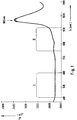
- Figure 1 shows an absorption spectrum of glucose in water.
- the decimal logarithm of the relation of measured intensity and irradiated intensity (lg I / I0) in transmission is plotted for a cuvette thickness of 1 cm and four glucose concentrations, namely 0.1.5 and 10%. It can be seen that the spectra for these four concentrations differ only slightly in a small wavelength range at approximately 980 nm. The maximum signal difference between the measured value with pure water and the 10% glucose solution at this wavelength is less than 2%. The difference is much smaller at other wavelengths.
- the variation of the glucose concentration used in the experiment is much larger than the real physiological glucose concentration. Based on a realistic glucose change in the physiological range of 100 mg / dl, the change at 980 nm corresponds to less than 0.02%.
- the change dI / dC of the measurement signal I as a function of the glucose concentration C is referred to below as "relative signal change" and is expressed quantitatively in% per 100 mg / dl change in the glucose concentration
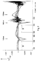
- FIG. 2 shows a similar spectrum in the subsequent wavelength range between approximately 1100 nm and 2500 nm. This is a difference spectrum for glucose concentrations between 0 and 600 mg / dl against pure water. Negative values mean a lower absorption compared to pure water. The maximum usable change in signal intensity is less than 0.3% overall, i.e. less than 0.05% on average per 100 mg / dl change in glucose concentration.
- Figures 1 and 2 show overall that the dependence of the absorption on the glucose concentration is so small over wide spectral ranges that it can practically not be used for measurement in a biological matrix.
- the spectral ranges with a "low" dependence of the absorption on the glucose concentration are the wavelength ranges in which the relative signal swing dI / dC in a transmission measurement on a clear glucose solution is less than 0.01% per 100 mg / dl change in the glucose concentration.
- the wavelengths around 980 nm, 1410 nm, 1890 nm and 2150 nm could be most suitable for the spectroscopic analysis of the glucose.
- the measurement should preferably be approximately monochromatic. "Monochromatic” is to be understood in the practical sense in that the major part of the intensity is emitted and / or detected in a relatively narrow wavelength range.
- the full width at half maximum should be less than 100 nm, preferably less than 50 nm.
- relatively broadband light sources such as light-emitting diodes or other semiconductor light sources can be used without subsequent spectral selection. This significantly reduces the cost of the equipment.
- the wavelength of the light source or the primary light, this statement relates to the wavelength of the intensity maximum.
- the at least two detection measurements are carried out at only one wavelength each.
- the fact that the measurement signal is largely independent of the wavelength makes it possible to select those wavelength ranges for the measurement in which the interference from strongly absorbing substances is as small as possible.
- the measured intensity is approximately independent of the concentration ratio between Hb and HbO2, because these substances have an isosbestic point there. This also applies in a broad isosbestic range between 1200 and 1300 nm.
- the absorption of hemoglobin and water is approximately the same in this range large. This results in a particularly good independence of the measured intensity from the ratio of Hb, HbO2 and H2O.
- a relative signal swing dI / dC is found in wavelength ranges in which the absorption has only a slight dependence on the glucose concentration, which is much larger than is to be expected on the basis of the absorption even in the narrow wavelength ranges , in which the absorption of the pure glucose solution is relatively strongly dependent on the glucose concentration.
- the value of the relative signal swing is dependent on the respective measurement setup, but is generally more than 0.5% per 100 mg / dl for measurements on human skin and is therefore at least ten times as large as the relative signal swing that is due to the change in absorption would be expected.
- the change in the glucose concentration leads to a change in the refractive index of the in the biological matrix contained liquid in which the glucose is dissolved.
- the change in the refractive index leads to a change in the light scattering at the scattering centers contained in the matrix.
- This change is extremely small for each individual spreading process.
- the change in the refractive index per mmol is only about 0.002%. In the context of the invention it was found that this extremely small effect for the analysis of glucose can be practically used if a large number of scattering processes of many photons which have undergone a mutually similar light path in the biological matrix are detected.
- the measuring method is thus designed in such a way that ideally the scattering behavior of the space surrounding the scattering centers, which is dependent on the refractive index, is determined within the biological matrix.
- this mechanism is very sensitive, i.e. the measured signals change strongly with relatively small changes in the glucose concentration.
- the increased sensitivity leads to improved selectivity compared to known in vivo analysis methods for glucose, because the variation of the multiple scattering used according to the invention in the most important biological matrices blood and skin tissue essentially depends only on the glucose concentration.
- MSAGD multiple scattering amplified glucose detection
- the effect on which the MSAGD is based represents a considerable disturbance in spectral analysis analyzes of other constituents of an optically heterogeneous biological matrix. It can therefore be advantageous to carry out at least one spatially resolved measurement of widely scattered light even with such a spectral analytical method for correcting changes in the optical path length caused by changes in the glucose concentration. Such a method is also the subject of the present invention.
- the MSAGD differs fundamentally from previous approaches to non-invasive analysis.
- infrared spectroscopy which is based on the measurement of the wavelength dependence of the absorption, the optical scattering is perceived as disturbing.
- parts of the body are selected where possible, which cause the least possible scattering of the light.
- NIR spectroscopic determinations on the antechamber of the eye which contains a relatively clear and therefore non-scattering liquid (US Pat. No. 4,014,321).
- the MSAGD signal also differs from absorption measurements in that the change in intensity as a function of the concentration dI / dC is largely independent of the wavelength.
- a certain change in the glucose concentration consequently leads to an approximately equal change in the intensity of the secondary light, even if the wavelength of the incident light differs by, for example, 100 nm.
- the change dI / dC in a more absorbing wavelength range is significantly higher than in a low-absorption wavelength range.
- This is used in spectroscopic measurements to use a wavelength with strong absorption as the measurement wavelength and a wavelength with weak absorption as the reference wavelength. This requires a narrow-band (“highly dispersive") measurement (with a half-value width less than 10 nm, often less than 1 nm) in a wide spectral range.
- Inexpensive semiconductor light transmitters in particular light-emitting diodes
- the location-dependent condition is to be understood such that the measurement of the secondary light (in contrast to EP-A-0 074 428) does not relate to a beam direction or an angular range of the light scattered by the measurement object or of the light reflected by the measurement object, but to one defined sub-area (area, district) of an interface delimiting the biological matrix, which is referred to as the detection site.
- the primary light is also irradiated in a defined partial area of an interface of the biological matrix, which is referred to as the irradiation site. Such a measurement is referred to as a "location-dependent detection measurement".
- the terms “irradiation site” and “detection site” are to be understood geometrically (for example in the sense of the English term “site”), namely as the partial area of the interface of a biological matrix on which light rays are decisive for the intensity measurement value in the respective detection measurement , pass through the interface.
- As a collective term for the place of entry and the detection location is therefore also referred to below as the "passage location”.
- the center of the irradiation site or the detection site Insofar as information about distances between passages is given below, these relate to the center of the irradiation site or the detection site. In the case of a circular design, the center is formed by the center point, in the case of an elongated design by the center line.
- the “multiple scattering condition” is to be understood in such a way that the places of passage (ie the irradiation site and the detection site) are arranged relative to one another in such a way that scattered light is detected at scattering centers of the biological matrix, the intensity of which is characteristic of the concentration of glucose. To ensure this, the following must be taken into account.
- the mean free path of photons in the tissue or the body fluids mentioned depends on the wavelength and the respective density and size of the scattering centers. It is typically between 0.01 mm and 0.1 mm. At least about 10, preferably at least about 100, scattering processes should take place on the light path in the biological matrix from the irradiation site to the detection site.
- the light path within the biological matrix is always longer (in many cases even considerably longer) than the direct connection between the radiation site and the detection site.
- the distance between the irradiation site and the detection site should correspond to at least ten times, preferably at least twenty times the mean free path of the photons in the respective biological matrix at the respective wavelength of the primary light.
- the maximum distance between the irradiation site and the detection site is also dependent on the mean free path of the photons. Above a limit to be determined experimentally in the individual case, the intensity of the signal drops in such a way that the signal / noise ratio becomes poor.
- the distance between the irradiation site and the detection site should preferably be less than 30 mm, particularly preferably less than 15 mm. In order to detect light that is widely scattered only at scattering centers of the biological matrix, care must also be taken to carefully shield the primary light from the detector with which the secondary light is measured.
- the multiple scattering means that the light emerging at the detection site is largely diffuse, i.e. its intensity is largely independent of the exit angle at which it is detected. If the primary light is coherent and / or polarized, these properties are largely lost due to the multiple scattering. For this reason, in general (unlike EP-A-0 074 428) the invention does not have to use a laser as the primary light source.
- the degree of polarization still obtained in the secondary light can also be used to test whether the "multiple scattering condition" required for the invention is fulfilled. For example, the degree of polarization of the secondary light should be less than 10% of an incident polarized primary light.
- the irradiation location and the detection location can have very different dimensions and geometrical shapes in the spatially resolved scattered light measurement. It is only essential that the spatially resolved scattered light measurement provides information about the intensity of the secondary light depending on the relative position of the irradiation site and the detection site (not depending on the detection angle). Several such spatially resolved measurements of widely scattered light, in which the respective detection location is at a different distance from the respective irradiation location, thus provide information I (D) about the functional dependence of the intensity I on the distance r.
- the irradiation location and especially the detection location in the case of spatially resolved scattered light measurement can have relatively large dimensions.
- embodiments are preferred in which the passage locations in the direction of the straight lines connecting the respective irradiation and detection locations (shortest connection) have a relatively small dimension of preferably less than 2 mm, particularly preferably less than 1 mm.
- the detection site is preferably located at the same interface as the irradiation site, i.e. it is measured "in reflection". As far as two opposite interfaces of the biological matrix are accessible, however, measurements can also be carried out “in transmission”, the radiation site and the detection location being on opposite interfaces of the biological matrix. In view of the diffuse nature of the light emerging at the detection location, the terms “transmission” and “reflection” must of course not be understood to mean that the secondary light emerges from the matrix with a strongly dominant preferred direction.
- the intensity measurement values of the at least two detection measurements are used to in one Evaluation step of the method using an evaluation algorithm and a calibration to determine the glucose concentration (“to be derived”). At least a first of these detection measurements must be a spatially resolved scattered light measurement. In principle, another method can also be used for a second detection measurement.
- Two or more spatially resolved scattered light measurements can also be carried out, from whose intensity measurements the glucose concentration is derived. It was found that from the dependency I (D) of the intensity I on the measuring distance D, which can be determined with at least two spatially resolved scattered light measurements, a particularly low-interference and therefore precise information about the glucose concentration is obtained.
- the two or more spatially resolved scattered light measurements are carried out at the same wavelength. If several light transmitters are used, it is sufficient if their wavelengths match the usual nominal fluctuations of light-emitting diodes with the same nominal wavelength.
- the term “light path” is of course not to be understood in the sense of a geometrically strictly limited partial volume of the biological matrix (as in classic transmission spectroscopy of a non-scattering liquid in a cuvette) because of the multiple scatter in the biological matrix.
- light path where it can be understood, for example, as the partial volume of the biological matrix in which a certain percentage (e.g. 70%) of the arriving from a certain irradiation location at a certain detection location, in which Matrix of widely scattered light is transported.
- a different light path in two spatially resolved scattered light measurements is realized in that the measuring distances between the irradiation site and the detection site differ sufficiently.
- the difference in intensity of the secondary light caused by the different light paths should make up at least a factor of 3, preferably at least a factor of 5, particularly preferably at least a factor of 10.
- An embodiment is particularly preferred in which at least two spatially resolving scattered light measurements with the same measuring distance between the irradiation site and the detection site are preferably carried out for two different measuring distances are carried out in which at least either the irradiation sites or the detection sites, preferably both the irradiation site and the detection site, differ.
- Such an embodiment does not seem sensible at first, because two measurements on the same biological matrix with the same length of light path should lead to the same result, i.e. no additional information would be obtained by the additional measurement.
- the additional measurement is redundant at the same measuring distance.
- redundant measurements are advantageous because they make it possible to identify and eliminate potential measurement errors due to inhomogeneities in the biological matrix (especially in skin tissue).
- the at least two detection measurements are preferably carried out simultaneously or at a sufficiently short time interval.
- a sufficiently short time interval is to be understood here at which there is no change in the biological matrix which impairs the measuring accuracy between the measurements which are used to derive a concentration value of the glucose.
- switchable irradiation means and / or detection means are provided in order to enable the setting of different pairs of passages without moving parts.
- the blood pulse can either be averaged over a sufficient number of pulse periods or measured synchronously with the pulse.
- the variation in body temperature can be recorded and used for compensation.
- the detection area in which the passage fields are located is actively thermostatted. Since a relatively high energy consumption is associated with such a temperature control, the measuring range is carefully thermally insulated in a device for in-vivo analysis preferred in the context of the invention.
- the invention does not differ significantly from known analysis methods which, as explained above, also require calibration in order to assign the measured variable (for example the color change in colorimetric tests) to the respective concentration.
- the algorithm in the present invention contains a simple predetermined mathematical function in order to determine an intermediate variable from the intensity measurement values I of the detection measurements, which can be referred to as the measurement result R.
- a simple quotient formation between the intensity measurement values of the first and second detection measurements has proven to be very effective.
- the measurement result R can then be linked in a known manner with the concentration C of glucose.
- an optically heterogeneous biological matrix 10 is shown symbolically as a cuboid in FIGS. 4 to 7. It is delimited by an upper interface 11a and a lower interface 11b.
- the biological matrix can be blood, for example, in which case the interfaces run along the inner walls of an optically transparent vessel (cuvette) in which the blood is for analytical in-vitro analysis.
- the biological matrix is a tissue, the interface is formed by the surface of the tissue.
- FIGS. 4 to 8 illustrate different variants of possible arrangements of one or more irradiation locations 12 or one or more detection locations 14 on a biological matrix 10 in a spatially resolved scattered light measurement in the sense of the invention.
- the irradiation locations 12 are each designed as narrow, elongated radiation fields 12a-12f and the detection locations as elongated, narrow detection fields 14a-14i.
- Such an elongated shape of the passage locations 12, 14 has proven to be a practically well usable compromise between the requirements of a good spatial resolution and a sufficient intensity of the irradiated or measured light at a reasonable manufacturing cost.
- the length of a passage field should be at least three times, preferably at least ten times as large as its width.
- the average width of the passage fields is preferably at most 2 mm, particularly preferably at most 1 mm. As far as special features of the elongated shape are not important, similar considerations also apply to point or circular passages.
- the primary light 15 is irradiated into the matrix 10 by an irradiation field 12a and the secondary light 17 is detected, which emerges from two detection fields 14a and 14b running at different measuring distances D1 and D2 to the irradiation field 12a.
- the primary light 15 enters the biological matrix 10 through an irradiation field 12b and the secondary light 17 exits from it through two detection fields 14c and 14d, the detection fields at different lateral measurement distances D1 and D2 from the irradiation field 12b are arranged.
- the detection fields 14c and 14d are located on the interface 11b, that of the interface 11a through which the Primary light 15 is radiated, is opposite.
- the entry field and exit field are preferably arranged in such a way that, in the case of at least two pairs of passage fields, the surface of the exit field is not crossed by any straight line crossing the surface of the radiation field at right angles.
- the detection field should not be arranged exactly opposite the radiation field, but should always be laterally offset from it.
- the biological matrix is a tissue, in particular skin tissue
- an interface delimiting the matrix namely the surface of the skin
- the body parts preferred in the context of the invention namely the fingertip, the trunk, the nail bed, the sclera or the inner upper arm of the person.
- the measurement which is preferred in the context of the present invention in the reflection method is possible, in which the irradiation of the primary light and the detection of the secondary light take place at the same interface of the matrix.
- two opposite interfaces 11a, 11b are also available for the in vivo analysis on skin tissue.
- the primary light is emitted by two radiation fields 12c, 12d in the biological matrix 10 is irradiated and the secondary light 17 emerging from the detection field 14e is detected.
- the radiation fields 12d and 12c are arranged at different measuring distances D1 and D2 from the detection field 14e, so that in this embodiment there is also the possibility of measuring the secondary light emerging from the detection field 14e as a function of the measuring distance from the respective radiation field 12c or 12d in order to derive a measured variable from the two measured values which is a measure of the concentration of the analyte in the biological matrix.
- the secondary light components that result from the primary light of the two different radiation fields must of course be separated from one another. This can expediently be carried out by irradiation separated in time, but the irradiation must take place at a sufficiently narrow time interval in the sense of the definition given above.
- the maximum measuring distance D2 between an irradiation location and a detection location of a spatially resolved scattered light measurement is 30 mm.
- the shorter distance D1 should be at least 0.5 mm, preferably at least 1 mm.
- the detection locations lie in a detection area 16 (shown in dashed lines in the figure) which includes the part of the interface 11a which is at a distance of at least 0.5 mm, preferably at least 1 mm and at most 30 mm from the center of the irradiation location 12 has.
- the corresponding values apply to the irradiation region 18 shown in dashed lines there.
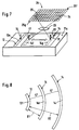
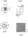
- FIG. 7 shows an embodiment in which a multiplicity of different detection fields 14f can be set on the interface 11a within a detection area 22, which run at different distances from an irradiation field 12e.
- this is achieved in that the detection area 22 is imaged by an optical imaging system symbolized as a lens 23 into an image plane 24 in which there is a two-dimensional arrangement 26 of light-sensitive elements, which are implemented, for example, as CCDs 25 (charge coupled device) .
- CCDs 25 charge coupled device
- the optical imaging corresponds to a specific detection field to a specific partial area of the CCD matrix 25.
- the field 14f is mapped to the row 25f and the field 14g to the row 25g of the CCD matrix 25.
- a specific detection field can consequently be set in a simple manner in that the intensity measurement signals are processed further by those light-sensitive elements to derive the concentration onto which the desired detection field is mapped.
- the terms “radiation field” and “detection field” or “radiation location” and “detection location” are to be understood geometrically. It is not absolutely necessary for any components of the analysis device to touch the interface of the biological matrix, for example the surface of the skin, and to be in contact with the radiation site or the detection site. It is only necessary that the irradiation location and the detection location are defined for each measuring distance, i.e. the primary light is radiated in at a specific and limited irradiation location and the secondary light is detected in such a locally defined manner that it is known from which specific delimited partial area of the interface (detection location) the secondary light has emerged, the intensity of which is detected in each case. Such a measuring process must take place with at least two different light paths between the irradiation site and the detection site in order to derive the measurement parameter characteristic of the analysis from the intensity measurement values measured therefrom.
- Figure 8 illustrates that the narrow, elongated shape of the fields need not necessarily be straight (as in Figures 4 to 7).
- a radiation field 12f in the form of a section of a circular ring is shown in a view of an interface.
- Two detection fields 14h and 14i likewise run in the form of circular ring sections at different distances from the radiation field 12f.
- the circular rings are concentric, so that the detection fields 14h and 14i are evenly spaced from the radiation field 12f.
- a good spatial resolution is achieved if the light is irradiated at a narrowly limited (point-shaped) radiation site and the detection site is one Forms a circle or section of a circle around this irradiation site.
- the detection site is one Forms a circle or section of a circle around this irradiation site.
- the passage fields (measured from center to center) run at a uniform distance D1, D2.
- the radiation site and the detection site should always be separated by a strip 47 (FIG. 8) of essentially uniform width.
- the dimension of the detection field in the direction of the shortest connection to the irradiation field (ie in the direction of the distance arrows D1, D2) should be less than 2 mm, preferably less than 1 mm, on average.
- Figures 9 to 12 show in a schematic representation (with a view of the interface) different arrangements in which redundant measurements are possible, i.e. several spatially resolved scattered light measurements with the same measuring distances and the same measuring wavelength, but different irradiation and / or detection locations.
- two elongated, rectangular detection fields 14k, 14l are arranged at equal distances between two likewise rectangular radiation fields 12g, 12h. All passage areas run parallel to each other. It is clear that a first measuring distance D1 can be set both by combining the radiation field 12g and the detection field 14k and by combining the radiation field 12h and the detection field 14l. A second larger measuring distance D2 results from the combination of the passage fields 12g with 14l or 12h with 14k.
- FIG. 10 shows a corresponding linear arrangement with two outer irradiation locations 12.
- Five detection locations 14 are arranged at regular intervals on the connecting line between the irradiation locations 12.
- all of the passages are point-shaped with a suitably round cross-section.
- the symbolic representation as squares and circles is only intended to facilitate the differentiation of the irradiation locations 12 and the detection locations 14.
- five different measuring distances D1 to D5 can each be set in two ways with different irradiation and detection locations, as shown in the figure.
- three irradiation locations 12 are combined with six detection locations.
- the irradiation locations 12 are arranged on a straight line at equal distances.
- the detection locations are located on a circle around the central irradiation location. In general, they should be distributed mirror-symmetrically around the straight line on which the irradiation locations are arranged. With this arrangement, there is a sixfold redundancy with respect to the central irradiation location 12 because each of the detection locations 14 is positioned at the same distance D1 from the central irradiation location.
- each of these irradiation locations is combined with two detection locations can, which are located in the corresponding distances D2 to D4.
- Such an arrangement enables high redundancy with relatively few components, because each measuring distance can be set with more than two different combinations of irradiation location 12 and detection location 14.
- arrangements with at least three different irradiation sites and at least three different detection sites are particularly preferred, which enable the setting of several different measuring distances, each with at least three different pairs of irradiation site and detection site. At least three times the redundancy has the advantage that it is generally recognizable if one of the stray light measurements from the other two stray light measurements deviates.
- the irradiation locations and the detection locations can be exchanged. For cost reasons, however, it is more advantageous to provide more detection sites than irradiation sites.
- a multiplicity of irradiation locations 12 and detection locations 14 are arranged alternately in a checkerboard fashion such that each irradiation location is surrounded by four detection locations and each detection location is surrounded by four irradiation locations.
- Redundant measurement arrangements make it possible to recognize and eliminate potential measurement errors due to inhomogeneities in the biological matrix. For this purpose, several measurements with the same measuring distances but different irradiation and / or detection locations are carried out and compared with one another. With a homogeneous structure of the examined biological matrix, the same intensity of the detected secondary light would have to be measured (with the same intensity of the incident primary light). Deviations suggest that disturbing structures (for example scars, hair or fibromas) are present in the examined partial area of the skin surface, which falsify the measurement result. This can be corrected in different ways.
- disturbing structures for example scars, hair or fibromas
- the measuring head placed on the skin can be moved to a different position in order to change the examined partial area of the skin surface ("measuring focus") so that the inhomogeneities lie outside the measuring focus.
- measuring focus the examined partial area of the skin surface
- averaging can be considered for a very large number of measurements. Of course, these measures can also be used in combination.
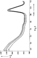
- the course of the measured intensity I is recorded as a function of the measuring distance D between the respective detection site and the irradiation site. If the detection locations are closely adjacent, a practically continuous curve I (D) results, which represents the profile of the detected secondary light as a function of the distance between the respective irradiation location and the respective detection location.
- a suitable regression algorithm known for such purposes can be used to derive the measurement variable characteristic of the analysis (for example PLS).
- the embodiment with a detection area in which a large number of different partial areas can be set as detection locations can of course also be implemented without the optical imaging system 23 shown in FIG. 7.
- suitable means such as, for example, screens, light guides or the like
- each light-sensitive element is made up of a specific Secondary light emerging from the delimited partial region of the interface 11a.
- Such an implementation is for the Embodiments according to FIGS. 10 to 12 are particularly suitable and can be integrated in one structural unit.
- both the irradiation location 12 and the detection location 14 should have a small dimension of at most 2 mm, preferably at most 1 mm, in the direction of the straight lines connecting the two fields.
- the different detection locations and / or irradiation locations by means of which the different measuring distances are realized are preferably spatially separated (not overlapping).
- An embodiment in which a multiplicity of different detection locations can be detected by means of a two-dimensional arrangement of light-sensitive elements opens up a number of additional possibilities, which are explained below.
- the detection locations should be adjustable in close succession.
- At least two, preferably at least four, particularly preferably at least eight different detection sites per cm can preferably be set in at least one dimension, particularly preferably in two dimensions.
- measuring focus On the one hand, it is possible to find a specific measuring position on a skin surface ("measuring focus"). For example, with the help of a pattern recognition process, characteristic structures of the surface can be recognized. Alternatively or additionally, a marking (for example by means of a tattoo that is invisible in normal light but contrasting in NIR light) can be provided by the skin two-dimensional arrangement of light-sensitive elements is recognized and localized.
- a second important possibility is the separation of the change in intensity caused by absorption on the one hand and scattering on the other.
- intensity profiles must be measured with the aid of a two-dimensional arrangement of light-sensitive elements at different wavelengths.
- an arrangement with many irradiation and detection locations arranged close to one another in a matrix-like manner can advantageously be used, alternating light with at least two different wavelengths being irradiated or detected in the matrix.
- the arrangement essentially corresponds to FIG. 12, apart from the use of several wavelengths, but not necessarily a regular checkerboard pattern with a regularly alternating arrangement of the irradiation and detection locations must be used.
- the number of different wavelengths preferably corresponds to the number of essential interference components plus a further wavelength.
- at least four different wavelengths are preferred with regard to the three most important interference components Hb, HbO2 and H2O.
- the influences of the scattering coefficient and the absorption coefficient can be separated from these measurement results by means of known procedures. Taking into account the knowledge of the present invention about the MSAGD effect, it is possible with such a two-dimensional multi-wavelength measurement to largely eliminate the interfering influences of the strongly absorbing substances when determining the glucose concentration by means of the present invention, or vice versa, for example, in a spectral analysis based determination of the concentration of Hb and HbO2 also largely suppress the disturbances that can be attributed to different glucose concentrations.
- FIGS. 13 to 15 show a practical embodiment of a measuring head 30 which is suitable for the invention and which is particularly suitable for the in vivo determination of glucose in human tissue.
- the measuring head 30 has a skin contact part 31 which is approximately circular in shape and which is fastened to a measuring head housing 32.
- the skin contact part 31 is placed on the surface of the skin 33 during use and lightly pressed.
- a square light transmission area 34 At its center is a square light transmission area 34, the is shown enlarged in FIG. It contains five rows 35 to 39 of optical fibers 29, which in the example shown consist of thirty-two fibers each with a diameter of 0.25 mm.
- the optical fibers 29 are each arranged in the light transmission region 34 such that their end faces lie flush in a common flat contact surface 42 and are in direct contact with the skin when the skin contact part 31 is placed on the skin 33.
- the row 35 of optical fibers defines an irradiation location.
- the optical fibers 29 of this series are connected by a cable 40 to a central unit, not shown, in which there is a preferably monochromatic light source, for example a light-emitting diode or a laser diode, the light of which is coupled into the optical fibers 29.
- the optical fibers 29 form light irradiation means 27 for specifically illuminating a defined irradiation location on a skin surface.
- part of the series 35 optical fibers is used to control the constancy of the light source.
- sixteen of the thirty-two fibers were used to irradiate the light and the other sixteen fibers to control the light intensity, the latter being combined separately from the former and fed to a photosensitive element.
- Photodiodes for example, which are arranged in the measuring head 30 can be used as the measuring receiver. It is useful for each row 36 to 39 of optical fibers 29, each a possible detection location define a common measuring receiver. The optical fibers of these rows are thus combined to a respective measuring receiver, at which the light emerging from these optical fibers is detected. The rows 36 to 39 of the optical fibers 29 together with the measurement receiver (not shown) each form detection means 28 for targeted measurement of the secondary light emerging at a defined detection location.
- the end faces of the optical fibers of the rows 35 to 39 each terminate flush or slightly protrude from the skin contact surface 42 which delimits the light emission region 34 downwards. This prevents light from reaching the skin surface directly from the irradiation location defined by row 35 to one of the detection sites defined by rows 36 to 39.
- the glass fibers of different rows are optically carefully separated from one another within the measuring head 30, so that no transmission of primary light to the detection means can take place.
- the measuring head 30 is intended in particular for monitoring the blood glucose level of diabetics.
- it is attached to a suitable location, for example on the upper abdominal wall on the skin. This can be done for example with the help of an adhesive tape.
- the contact surface 42 should be pressed on with a sufficiently firm and even pressure.
- the skin contact part 31 has a ring 31a, the diameter of which is substantially larger than that of the light transmission region 34. It consists of an opaque material and closes with its Edge 31b off the skin.
- the primary light can be modulated with a certain frequency and can be selectively detected in a narrow-band manner depending on the frequency (for example with the aid of a lock-in amplifier), in order to reduce the effects of stray light.
- the light transmission region 34 is surrounded by an annular heating surface 41, in which a surface resistance heater is arranged. This can be regulated to a predetermined temperature, for example 37 °, with the aid of an NTC resistor and a PD controller.
- FIG. 16 shows analysis results which were achieved on the one hand with a reference method and on the other hand with a device according to the invention (embodiment according to FIGS. 13 to 15).
- the concentration C is plotted in mmol / l over the time t in minutes.
- the solid line 45 marks the results of an enzymatic analysis of the glucose in the patient's blood used as a reference method, while the rectangular markings are 46 measuring points with the device according to the invention.
- a measuring head according to FIGS. 13 to 15 was used, the light from a light-emitting diode with 1 mW power and a wavelength of 805 nm being radiated into the skin through the optical fiber series 35 and detected through the series 38 and 39.
- R characteristic of the concentration the quotient was formed between the intensity I1 of the light measured on the row 39 and the intensity I2 of the light measured on the row 38.
- FIG. 16 shows an excellent agreement between the conventionally in vitro blood and the values according to the invention in vivo in the skin tissue over a period of five and a half hours.
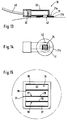
- FIGS. 17 and 18 show a measuring holder 50 for determining the glucose concentration in a finger 51.
- the finger 51 is inserted into a precisely fitting channel 52 which is formed in a holder block 53.
- the mounting block 53 consists of aluminum or another good heat-conducting material, which is set with a heating and thermostating device, not shown, to a defined temperature, which is preferably slightly above the normal body temperature (above 37 ° C.).
- the wall element 54 which laterally delimits the channel 52 can be displaced such that the width of the channel 52 can be adapted to the finger 51 of the respective patient.
- fixing elements 55 are provided which are slidably guided in the direction of the finger 51 and are pressed against the finger 51 with a spring (not shown).
- the mounting block 53, the wall elements 54 and the fixing elements 55 together form the channel 52 stop 56 delimiting in the insertion direction overall fixation means, by means of which the finger 51 is positioned in a position that is as reproducible as possible with respect to the measuring device designated overall by 58.
- light irradiation means 27 are formed by a light-emitting diode (not shown) and by a light guide channel 59, through which primary light is directed to a circular irradiation site of approximately 1 mm in diameter on the underside of the tip of the finger 51.
- a detection area 16 three detection locations 14 are provided which concentrically surround the irradiation site 12 as semicircular detection fields 14k-14m.
- the detection means 28 as can be seen more clearly in FIG.
- An infrared temperature sensor 60 is directed to a temperature measuring location 61 which should be as close as possible to the detection area 16.
- FIG. 20 shows an example of the block diagram of an electronic circuit 65 which is suitable as an evaluation means for a measuring device according to the invention.
- a voltage-current converter 67 is driven by an oscillator 66 and feeds the light-emitting diode 68, which serves as a light source.
- the temperature of the light-emitting diode 68 can optionally be monitored by an NTC 69 in order to improve the constancy of the intensity of the emitted light.
- the output signals of the measuring receivers (photodiodes) 70a-70c are applied to lock-in amplifiers 72a-72c via a preamplifier circuit 71a-71c, to which the signal of the oscillator 66 is also fed as a reference.
- the output signals of the lock-in amplifiers 72a-72c are digitized in an A / D converter unit 73 and fed to a microcomputer central unit 74.
- the microcomputer central unit furthermore receives the signals of the NTC 69 (amplified by a preamplifier 69a) and a temperature sensor 75 (amplified by a preamplifier 75a) for measuring the temperature in the detection area, which preferably (like the IR sensor 60 of the embodiment according to FIG 17) works without contact.
- semiconductor light receivers 80 for example photodiodes
- semiconductor light transmitters 81 for example light emitting diodes
- the semiconductor light transmitter 80 and the semiconductor light receiver 81 are integrated in the same component 83, the arrangement being shown only schematically without structural details.
- the practical implementation can be carried out using an integration technology customary in electronics, for example by monolithic integration in a chip or in hybrid technology. It is essential that both the light transmitters 81 and the light receivers 80 are in direct optical contact with the skin surface and are shielded from the neighboring elements so that they radiate the light into a defined irradiation location or detect it at a defined detection location.
- semiconductor light transmitter 81a and semiconductor light receiver 80a are drawn in white for a first wavelength, while semiconductor light transmitter 81b and semiconductor light receiver 80b are shown hatched for a second wavelength.
- both the setting of different measuring distances D and the setting of different wavelengths (if at all necessary) are carried out without moving parts. This is usually advantageous in terms of cost and reliability. Of course, alternatives with moving parts are also possible within the scope of the invention.
- Different measuring distances D can thus be set in that either the light irradiation means 27 or the detection means 28, for example with the aid of a spindle drive, the course I (D) of the intensity I being determined as a function of the measuring distance D by stepwise adjustment of this drive.
- a grating monochromator can be provided on the primary side or on the secondary side.
Abstract
Description
Die Erfindung betrifft ein Verfahren und eine Vorrichtung zur Analyse von Glucose in einer biologischen Matrix.The invention relates to a method and a device for analyzing glucose in a biological matrix.
Der Begriff "biologische Matrix" bezeichnet eine Körperflüssigkeit oder ein Gewebe eines lebenden Organismus. Biologische Matrices, auf die sich die Erfindung bezieht, sind optisch heterogen, d.h. sie enthalten eine Vielzahl von Streuzentren, an denen eingestrahltes Licht gestreut wird. Im Falle von biologischem Gewebe, insbesondere Hautgewebe, werden die Streuzentren von den Zellwänden und anderen in dem Gewebe enthaltenen Bestandteilen gebildet.The term "biological matrix" denotes a body fluid or a tissue of a living organism. Biological matrices to which the invention relates are optically heterogeneous, i.e. they contain a large number of scattering centers, at which incident light is scattered. In the case of biological tissue, in particular skin tissue, the scattering centers are formed by the cell walls and other components contained in the tissue.
Körperflüssigkeiten, insbesondere Blut, sind ebenfalls optisch heterogene biologische Matrices, weil sie Partikel enthalten, an denen Licht vielfach gestreut wird. Auch Milch und andere in der Lebensmittelchemie zu untersuchende Flüssigkeiten enthalten vielfach eine hohe Konzentration von Streuzentren, beispielsweise in Form von emulgierten Fetttröpfchen.Body fluids, especially blood, are also optically heterogeneous biological matrices because they contain particles on which light is scattered in many ways. Milk and other liquids to be examined in food chemistry often contain a high concentration from scattering centers, for example in the form of emulsified fat droplets.
Zur qualitativen und quantitativen analytischen Bestimmung von Komponenten solcher biologischen Matrices werden im allgemeinen Reagenzien bzw. Reagenziensysteme eingesetzt, deren Reaktion mit der jeweiligen Komponente zu einer physikalisch nachweisbaren Änderung, beispielsweise einer Änderung der Farbe der Reaktionslösung führt, die als Meßgröße gemessen werden kann. Durch Kalibration mit Standardproben bekannter Konzentration wird eine Korrelation zwischen den bei unterschiedlichen Konzentrationen gemessenen Werten der Meßgröße und der jeweiligen Konzentration bestimmt.For the qualitative and quantitative analytical determination of components of such biological matrices, reagents or reagent systems are generally used, the reaction of which with the respective component leads to a physically detectable change, for example a change in the color of the reaction solution, which can be measured as a measured variable. Calibration with standard samples of known concentration determines a correlation between the measured variable values measured at different concentrations and the respective concentration.
Diese Verfahren ermöglichen zwar Analysen mit hoher Genauigkeit und Empfindlichkeit, machen es jedoch erforderlich, eine flüssige Probe, insbesondere eine Blutprobe zur Analyse dem Körper zu entnehmen ("Invasive Analyse"). Diese Probenentnahme ist unangenehm und schmerzhaft und verursacht ein gewisses Infektionsrisiko.Although these methods enable analyzes with high accuracy and sensitivity, they make it necessary to take a liquid sample, in particular a blood sample, from the body for analysis ("invasive analysis"). This sampling is uncomfortable and painful and creates a certain risk of infection.
Dies gilt vor allem, wenn eine Krankheit sehr häufige Analysen erforderlich macht. Das wohl wichtigste Beispiel ist der Diabetes mellitus. Um schwere Folgeerkrankungen und kritische Zustände des Patienten zu vermeiden, ist es bei dieser Krankheit erforderlich, den Glucosegehalt des Blutes sehr häufig oder sogar kontinuierlich zu bestimmen.This is especially true when a disease requires very frequent analyzes. The most important example is diabetes mellitus. In order to avoid serious complications and critical conditions of the patient, it is necessary in this disease to determine the glucose content of the blood very often or even continuously.
Es sind deshalb bereits eine Vielzahl von Verfahren und Vorrichtungen vorgeschlagen worden, um Glucose in Blut, Gewebe oder anderen biologischen Matrices in vivo und nicht-invasiv zu bestimmen.A large number of methods and devices have therefore already been proposed for determining glucose in blood, tissue or other biological matrices in vivo and non-invasively.
Ein Überblick über physikochemische (reagenzienfreie) Bestimmungen von Glucose in vivo wird gegeben in: J.D. Kruse-Jarres "Physicochemical Determinations of Glucose in vivo", J. Clin. Chem. Clin. Biochem. 26 (1988), 201-208. Als nicht-invasive Verfahren werden dabei unter anderem die Kernresonanz (NMR, nuclear magnetic resonance), Elektronenspinresonanz (ESR, electron spin resonance) sowie die Infrarotspektroskopie genannt. Keines dieser Verfahren hat jedoch bis jetzt praktische Bedeutung erlangen können. Teilweise sind extrem große und aufwendige Apparaturen erforderlich, die für die Routineanalytik oder gar die Selbstkontrolle des Patienten (home monitoring) völlig ungeeignet sind.An overview of physicochemical (reagent-free) determinations of glucose in vivo is given in: JD Kruse-Jarres "Physicochemical Determinations of Glucose in vivo", J. Clin. Chem. Clin. Biochem. 26: 201-208 (1988). Nuclear resonance (NMR, nuclear magnetic resonance), electron spin resonance (ESR, electron spin resonance) and infrared spectroscopy are mentioned as non-invasive methods. However, none of these methods has so far been of practical importance. In some cases, extremely large and complex devices are required, which are completely unsuitable for routine analysis or even self-monitoring by the patient (home monitoring).
Die Erfindung bezieht sich auf eine Teilgruppe von nichtinvasiven Analyseverfahren, bei denen Licht durch eine die biologische Matrix begrenzende Grenzfläche als Primärlicht in die biologische Matrix eingestrahlt und die Intensität des nach Wechselwirkung mit der biologischen Matrix aus dieser als Sekundärlicht austretenden Lichts gemessen wird. Eine solche Messung wird hier als "Detektionsmessung" bezeichnet. Zur Bestimmung einer Glucosekonzentration werden bei den bekannten Verfahren mehrere Detektionsmessungen bei unterschiedlichen Wellenlängen durchgeführt. Aus der bei den Detektionsmessungen ermittelten spektralen Abhängigkeit der Intensität des Sekundärlichts wird ein Meßresultat abgeleitet, das (ohne Verwendung von Reagenzien) ein Maß für die Konzentration des Analyten in der biologischen Matrix ist. Die Wellenlängen des Lichts, die für solche Verfahren diskutiert werden, liegen allgemein zwischen etwa 300 nm und mehreren tausend nm, also im Spektralbereich zwischen dem nahen UV- und infrarotem Licht. Der Begriff "Licht" darf nicht als Einschränkung auf den sichtbaren Spektralbereich des Lichtes verstanden werden.The invention relates to a subset of non-invasive analysis methods in which light is radiated through an interface delimiting the biological matrix as primary light into the biological matrix and the intensity of the light emerging from this as secondary light after interaction with the biological matrix is measured. Such a measurement is referred to here as a "detection measurement". To determine a glucose concentration, several detection measurements are carried out at different wavelengths in the known methods. From the spectral dependence of the intensity of the secondary light determined in the detection measurements, a measurement result is derived which (without the use of reagents) is a measure of the concentration of the analyte in the biological matrix. The wavelengths of light that are discussed for such methods are generally between about 300 nm and several thousand nm, that is in the spectral range between the near UV and infrared light. The term "light" should not be understood as a restriction to the visible spectral range of light.
Nahezu alle bekannten Verfahren dieser Art basieren auf den Prinzipien der Spektroskopie. Grundlage ist dabei die Wechselwirkung des eingestrahlten Primärlichtes in bestimmten spektralen Bereichen mit Vibrations- und Rotationszuständen der zu analysierenden Moleküle. Die Vibrations- und Rotations-Grundzustände der Glucose befindet sich im IR-Bereich bei Wellenlängen von mehr als 2500 nm. Diese können wegen der starken Absorption des in biologischen Matrices stets in hoher Konzentration gegenwärtigen Wassers für die nicht-invasive Analyse von Glucose nicht verwendet werden. Im Bereich des nahen Infrarot (NIR) ist die Absorption des Wassers geringer (sogenanntes "Wasser-Transmissionsfenster"). Die spektrale Analyse von Glucose in diesem Bereich basiert auf der Absorption durch Obertöne (overtones) und Kombinationsschwingungen der Vibrations- und Rotationsgrundzustände des Glucosemoleküls (vgl. vorstehend zitierter Artikel von Kruse-Jarres und EP-A-0 426 358).Almost all known methods of this type are based on the principles of spectroscopy. The basis for this is the interaction of the incident primary light in certain spectral ranges with the vibration and rotation states of the molecules to be analyzed. The basic vibrational and rotational states of glucose are in the IR range at wavelengths of more than 2500 nm. These cannot be used for the non-invasive analysis of glucose due to the strong absorption of the water present in high concentrations in biological matrices . In the near infrared (NIR) range, the absorption of water is lower (so-called "water transmission window"). The spectral analysis of glucose in this area is based on the absorption by overtones and combination vibrations of the vibrational and rotational ground states of the glucose molecule (cf. article by Kruse-Jarres and EP-A-0 426 358 cited above).
Die praktische Realisierung eines nicht-invasiven Glucose-Sensors auf Basis dieser Prinzipien verursacht außerordentlich große Schwierigkeiten, die vor allem daraus resultieren, daß das Nutzsignal (die Änderung des Absorptions-Spektrums in Abhängigkeit von einer Änderung der Glucosekonzentration) sehr gering ist und diesem kleinen Nutzsignal ein großer Hintergrund von Störsignalen gegenübersteht, die insbesondere von der spektralen Absorption von Wasser und anderen stark absorbierenden Komponenten (unter anderem dem roten Blutfarbstoff Hämoglobin) resultieren. Zur Lösung dieses Problems wurden zahlreiche unterschiedliche Versuche unternommen:
- Es werden Differenz-Messungen bei unterschiedlichen Wellenlängen durchgeführt, wobei eine erste Wellenlänge so gewählt ist, daß die Glucose dort möglichst stark absorbiert, während eine zweite Wellenlänge als Referenzwellenlänge so gewählt ist, daß die Absorption bei unterschiedlichen Glucosekonzentrationen möglichst konstant ist (EP-A-0 160 768).
- In dem US-Patent 5,028,787 werden mit Hilfe von Computer-Untersuchungen Wellenlängenpaare ausgewählt, die sich in besonderem Maße für Absorptionsmessungen von Glucose eignen sollen. Als besonders gut geeignet wird das Wellenlängenpaar 945 nm und 1015 nm angesehen.
- In der WO 93/00856 werden zwei Wellenlängen so ausgewählt, daß der Extinktions-Koeffizient möglichst gleich ist. Die Intensität von zwei Strahlen mit diesen beiden Wellenlängen wird so abgeglichen, daß das detektierte Signal gleich groß ist. Änderungen der Glucosekonzentration sollen sich dabei als Änderungen des Differenzsignals zwischen beiden Wellenlängen nachweisen lassen.
- Differential measurements are carried out at different wavelengths, a first wavelength being chosen so that the glucose there is as possible strongly absorbed, while a second wavelength is chosen as the reference wavelength so that the absorption is as constant as possible at different glucose concentrations (EP-A-0 160 768).
- In US Pat. No. 5,028,787, computer pairs are used to select wavelength pairs which are said to be particularly suitable for absorption measurements of glucose. The wavelength pair 945 nm and 1015 nm is considered to be particularly suitable.
- In WO 93/00856 two wavelengths are selected so that the extinction coefficient is as equal as possible. The intensity of two beams with these two wavelengths is adjusted so that the signal detected is of the same size. Changes in the glucose concentration should be detectable as changes in the difference signal between the two wavelengths.
Weitere Verfahren und Vorrichtungen zur nichtinvasiven Analyse von Glucose werden beschrieben in den US-Patenten 5,086,229, 5,178,142, 5,179,951, 4,883,953, 4,882,492 und den PCT-Anmeldungen WO 92/17765 und WO 90/07905.Further methods and devices for the non-invasive analysis of glucose are described in US Patents 5,086,229, 5,178,142, 5,179,951, 4,883,953, 4,882,492 and PCT applications WO 92/17765 and WO 90/07905.
Trotz dieser Bemühungen ist es bisher nicht gelungen, einen praktisch funktionsfähigen nicht-invasiven Glucose-Sensor zur Verfügung zu stellen. Realistischer ist die Möglichkeit, mit einem auf den Prinzipien der Spektralanalyse basierenden In-vivo-Sensor die Konzentration von Substanzen zu bestimmen, die um mehrere Größenordnungen stärker als Glucose absorbieren. Wichtige Beispiele sind das stark absorbierende Hämoglobin (Hb) bzw. dessen oxidierte Form HbO₂. Da diese Parameter Auskunft über den Oxigenierungszustand des Blutes geben, werden solche Sensoren auch als Oximeter bezeichnet. Aus der Literatur sind zahlreiche unterschiedliche Konstruktionen und Verfahren für nicht-invasive Oximeter bekannt. Verwiesen sei beispielsweise auf WO 89/01758, US 4,867,557 (entsprechend EP-A-0 286 142) , EP-A-0 353 619, EP-A-0 104 772, WO 91/17697, WO 93/11701 (publiziert am 24.6.1993) und die US-Patente 5,057,695, 4,223,680, 4,295,470, 4,824,242.Despite these efforts, it has so far not been possible to provide a practically functional, non-invasive glucose sensor. It is more realistic to use an in vivo sensor based on the principles of spectral analysis to determine the concentration of substances that absorb several orders of magnitude more than glucose. Important examples are the highly absorbent hemoglobin (Hb) or its oxidized form HbO₂. Since these parameters provide information about the oxygenation state of the blood, such sensors are also referred to as oximeters. From the literature numerous different designs and methods for non-invasive oximeters are known. Reference is made, for example, to WO 89/01758, US 4,867,557 (corresponding to EP-A-0 286 142), EP-A-0 353 619, EP-A-0 104 772, WO 91/17697, WO 93/11701 (published on June 24, 1993) and U.S. Patents 5,057,695, 4,223,680, 4,295,470, 4,824,242.
In der europäischen Patentschrift 0 074 428 ist ein Verfahren und eine Vorrichtung zur quantitativen Bestimmung von Glucose durch Laser-Lichtstreuung beschrieben. Dabei wird davon ausgegangen, daß die Glucosemoleküle einen durch die Lösung transmittierten Lichtstrahl streuen und daß sich daraus die Glucosekonzentration ableiten läßt. Entsprechend dieser Theorie wird die Messung darauf ausgerichtet, daß die Information über die Glucosekonzentration aus der Raumwinkelverteilung des aus einer Untersuchungsküvette oder einem untersuchten Körperteil austretenden transmittierten Lichtes erhältlich ist. Insbesondere wird die Intensität des transmittierten Lichtes in einem Winkelbereich, in dem die Änderung in Abhängigkeit von der Glucosekonzentration möglichst groß ist, gemessen und in Beziehung zu der an dem Zentralstrahl, welcher die Probe in gerader Richtung durchdringt, gemessenen Intensität gesetzt. Zur in vivo-Analyse wird ausschließlich eine Transmissionsmessung mit Laserlicht am Ohrläppchen empfohlen.
Mit ähnlichen wissenschaftlichen Überlegungen befaßt sich auch die Publikation von I.S. Chira et al.:
"Light Scattering by Blood Components after Supplying Glucose", Biomed. Technik 35 (1990), 102-106. Darin wird experimentell die Möglichkeit untersucht, die Glucose-Konzentration in Flüssigkeiten mittels Lichtstreuung zu bestimmen. Die Autoren kommen zu dem Ergebnis, daß dies weder mit statischen Lichtstreuexperimenten noch mit der Photonen-Korrelations-Spektroskopie (PCS) möglich ist.The publication by IS Chira et al deals with similar scientific considerations:
"Light Scattering by Blood Components after Supplying Glucose", Biomed. Technik 35: 102-106 (1990). This experimentally examines the possibility of determining the glucose concentration in liquids by means of light scattering. The authors conclude that this is neither with static light scattering experiments nor with photon correlation spectroscopy (PCS) is possible.
Der Erfindung liegt die Aufgabe zugrunde, ein Verfahren für die analytische Bestimmung von Glucose in einer biologischen Matrix zur Verfügung zu stellen, welches mit einfachen Mitteln, reagenzienfrei und nicht-invasiv arbeitet und eine gute Analysegenauigkeit, zum Beispiel für die Beobachtung der Änderung der Analytkonzentration (Verlaufskontrolle) über einen ausreichenden Zeitraum, ermöglicht.The invention has for its object to provide a method for the analytical determination of glucose in a biological matrix which works with simple means, reagent-free and non-invasive and good analytical accuracy, for example for observing the change in analyte concentration ( Follow-up) over a sufficient period of time.
Die Aufgabe wird gelöst durch ein Verfahren zur Bestimmung der Konzentration von Glucose in einer biologischen Matrix, umfassend mindestens zwei Detektionsmessungen, bei denen jeweils Licht durch eine die biologische Matrix begrenzende Grenzfläche als Primärlicht in die biologische Matrix eingestrahlt wird, das Licht in der biologischen Matrix entlang einem Lichtweg propagiert und eine aus der biologischen Matrix durch eine diese begrenzende Grenzfläche als Sekundärlicht austretende Lichtintensität gemessen wird, und einen Auswerteschritt, bei dem aus den Intensitätsmeßwerten der Detektionsmessungen mittels eines Auswertealgorithmus und einer Kalibration die Glucosekonzentration abgeleitet wird, bei welchem mindestens eine Detektionsmessung eine ortsaufgelöste Messung von vielfach gestreutem Licht ist, bei der das Primärlicht an einem definierten Einstrahlungsort in die biologische Matrix eingestrahlt wird, die Intensität des an einem definierten Detektionsort aus der biologischen Matrix austretenden Sekundärlichts gemessen wird und der Detektionsort relativ zu dem Einstrahlungsort so angeordnet ist, daß an Streuzentren der biologischen Matrix vielfach gestreutes Licht detektiert wird, dessen Intensität für die Konzentration der Glucose charakteristisch ist.The object is achieved by a method for determining the concentration of glucose in a biological matrix, comprising at least two detection measurements, in each of which light is irradiated as primary light into the biological matrix through an interface delimiting the biological matrix, along the light in the biological matrix propagates a light path and a light intensity emerging from the biological matrix through a boundary surface delimiting this as secondary light is measured, and an evaluation step in which the glucose concentration is derived from the intensity measurement values of the detection measurements by means of an evaluation algorithm and a calibration, in which at least one detection measurement is a spatially resolved one Measurement of widely scattered light, in which the primary light is irradiated into the biological matrix at a defined irradiation location, is the intensity of the biolog at a defined detection location Ischen matrix emerging secondary light is measured and the detection site is arranged relative to the irradiation site so that multiple scattered light is detected at scattering centers of the biological matrix, the intensity of which is characteristic of the concentration of glucose.
Gegenstand der Erfindung ist weiterhin eine Vorrichtung zur Bestimmung der Konzentration von Glucose in einer biologischen Matrix, insbesondere zur Durchführung des erfindungsgemäßen Verfahrens, mit einem zum Anlegen an eine Grenzfläche der biologischen Matrix vorgesehenen Lichttransmissionsbereich, Einstrahlungsmitteln zum Einstrahlen von Licht in die biologische Matrix durch eine diese begrenzende Grenzfläche, Detektionsmitteln zum Messen der Intensität von aus der biologischen Matrix durch eine diese begrenzende Grenzfläche austretendem Licht und Auswertemitteln zum Umwandeln der gemessenen Intensität in ein der Glucosekonzentration entsprechendes Signal, bei welchem die Einstrahlungsmittel zum gezielten Beleuchten eines definierten Einstrahlungsortes ausgebildet sind und die Detektionsmittel zum gezielten Messen des an einem definierten Detektionsort austretenden Sekundärlichts ausgebildet sind, wobei der Detektionsort relativ zu dem Einstrahlungsort so angeordnet ist, daß an Streuzentren der biologischen Matrix vielfach gestreutes Licht detektiert wird, dessen Intensität für die Konzentration der Glucose charakteristisch ist.The invention further relates to a device for determining the concentration of glucose in a biological matrix, in particular for carrying out the method according to the invention, with a light transmission region provided for application to an interface of the biological matrix, and irradiation means for irradiating light into the biological matrix through it Boundary boundary, detection means for measuring the intensity of light emerging from the biological matrix through a boundary boundary and evaluation means for converting the measured intensity into a signal corresponding to the glucose concentration, in which the radiation means are designed for the targeted illumination of a defined radiation location and the detection means for targeted measurement of the secondary light emerging at a defined detection location are formed, the detection location being arranged relative to the irradiation location in such a way that at scattering centers in the biological matrix multiply scattered light is detected, the intensity of which is characteristic of the concentration of glucose.
Für die Erfindung ist kennzeichnend, daß eine für die Glucosekonzentration charakteristische Meßgröße ohne Messung mehrerer Wellenlängen dadurch bestimmt werden kann, daß zwei Detektionsmessungen (bei vorzugsweise gleicher Meßwellenlänge, aber mit unterschiedlichen Lichtwegen) stattfinden, wobei wenigstens eine der Detektionsmessungen eine ortsaufgelöste Messung von vielfach gestreutem Licht ist. Im Gegensatz zu vorbekannten spektroskopischen Verfahren (insbesondere NIR-Spektroskopie) geht es dabei nicht darum, die optische Absorption als Maß für die Glucose zu bestimmen. Die Wellenlänge wird vorzugsweise sogar in einem Spektralbereich gewählt, in dem die Absorption der Glucose verhältnismäßig gering ist.It is characteristic of the invention that a measurement variable characteristic of the glucose concentration can be determined without measuring several wavelengths by taking two detection measurements (with preferably the same measurement wavelength, but with different light paths), at least one of the detection measurements being a spatially resolved measurement of light that is scattered many times over is. In contrast to previously known spectroscopic methods (in particular NIR spectroscopy), it is not a matter of determining the optical absorption as a measure of the glucose. The wavelength is preferably even selected in a spectral range, in which the absorption of glucose is relatively low.
Figur 1 zeigt ein Absorptionsspektrum von Glucose in Wasser. Aufgetragen ist dabei der dekadische Logarithmus der Relation aus gemessener Intensität und eingestrahlter Intensität (lg I/I₀) in Transmission für eine Küvettendicke von 1 cm und vier Glucosekonzentrationen, nämlich 0,1,5 und 10%. Man erkennt, daß sich die Spektren für diese vier Konzentrationen nur in einem kleinen Wellenlängenbereich bei etwa 980 nm geringfügig unterscheiden. Der maximale Signalunterschied zwischen dem Meßwert mit reinem Wasser und der 10%-igen Glucoselösung bei dieser Wellenlänge ist kleiner als 2 %. Bei anderen Wellenlängen ist der Unterschied noch wesentlich geringer. Dabei ist die in dem Experiment verwendete Variation der Glucosekonzentration sehr viel größer als die reale physiologische Glucosekonzentration. Bezogen auf eine realistische Glucoseänderung im physiologischen Bereich von 100 mg/dl entspricht die Änderung bei 980 nm weniger als 0,02 %. Die Änderung dI/dC des Meßsignals I in Abhängigkeit von der Glucosekonzentration C wird nachfolgend als "relativer Signalhub (relativ signal change)" bezeichnet und quantitativ in % je 100 mg/dl Änderung der Glucosekonzentration ausgedrückt.Figure 1 shows an absorption spectrum of glucose in water. The decimal logarithm of the relation of measured intensity and irradiated intensity (lg I / I₀) in transmission is plotted for a cuvette thickness of 1 cm and four glucose concentrations, namely 0.1.5 and 10%. It can be seen that the spectra for these four concentrations differ only slightly in a small wavelength range at approximately 980 nm. The maximum signal difference between the measured value with pure water and the 10% glucose solution at this wavelength is less than 2%. The difference is much smaller at other wavelengths. The variation of the glucose concentration used in the experiment is much larger than the real physiological glucose concentration. Based on a realistic glucose change in the physiological range of 100 mg / dl, the change at 980 nm corresponds to less than 0.02%. The change dI / dC of the measurement signal I as a function of the glucose concentration C is referred to below as "relative signal change" and is expressed quantitatively in% per 100 mg / dl change in the glucose concentration.
Figur 2 zeigt ein ähnliches Spektrum im anschließenden Wellenlängenbereich zwischen etwa 1100 nm und 2500 nm. Es handelt sich dabei um ein Differenzspektrum für Glucosekonzentrationen zwischen 0 und 600 mg/dl gegen reines Wasser. Negative Werte bedeuten dabei eine im Vergleich zum reinen Wasser verringerte Absorption. Dabei beträgt die maximale nutzbare Änderung der Signalintensität insgesamt weniger als 0,3 %, also im Mittel weniger als 0,05 % je 100 mg/dl Änderung der Glucosekonzentration.FIG. 2 shows a similar spectrum in the subsequent wavelength range between approximately 1100 nm and 2500 nm. This is a difference spectrum for glucose concentrations between 0 and 600 mg / dl against pure water. Negative values mean a lower absorption compared to pure water. The maximum usable change in signal intensity is less than 0.3% overall, i.e. less than 0.05% on average per 100 mg / dl change in glucose concentration.
Die Figuren 1 und 2 zeigen insgesamt, daß über weite Spektralbereiche die Abhängigkeit der Absorption von der Glucosekonzentration so gering ist, daß sie zur Messung in einer biologischen Matrix praktisch nicht genutzt werden kann. Als Spektralbereiche mit einer "geringen" Abhängigkeit der Absorption von der Glucosekonzentration werden die Wellenlängenbereiche angesehen, in denen der relative Signalhub dI/dC bei einer Transmissionsmessung an einer klaren Glucoselösung weniger als 0,01 % je 100 mg/dl Änderung der Glucosekonzentration beträgt.Figures 1 and 2 show overall that the dependence of the absorption on the glucose concentration is so small over wide spectral ranges that it can practically not be used for measurement in a biological matrix. The spectral ranges with a "low" dependence of the absorption on the glucose concentration are the wavelength ranges in which the relative signal swing dI / dC in a transmission measurement on a clear glucose solution is less than 0.01% per 100 mg / dl change in the glucose concentration.
Aufgrund der in den Figuren 1 und 2 dargestellten Meßergebnisse könnten am ehesten die Wellenlängen um etwa 980 nm, 1410 nm, 1890 nm und 2150 nm zur spektroskopischen Analyse der Glucose geeignet sein.On the basis of the measurement results shown in FIGS. 1 and 2, the wavelengths around 980 nm, 1410 nm, 1890 nm and 2150 nm could be most suitable for the spectroscopic analysis of the glucose.
Im Rahmen der vorliegenden Erfindung sind dagegen die Spektralbereiche mit geringer Abhängigkeit der Absorption einer wässrigen Glucoselösung von der Glucosekonzentration vorteilhaft einsetzbar. Konkret sind sind etwa die Wellenlängen zwischen 400 nm und 940 nm, zwischen 1020 nm und 1390 nm, zwischen 1430 nm und 1880 nm, zwischen 1900 und 2050 nm sowie zwischen 2250 und 2500 nm geeignet. Besonders bevorzugt sind die in den Figuren 1 und 2 mit römischen Ziffern bezeichneten Wellenlängenbereiche, nämlich:
- I. 400
bis 600 nm. - II. 750 bis 850 nm, vorzugsweise 780 bis 920 nm, besonders bevorzugt 780 bis 825 nm oder 850
bis 900 nm. - III. 1050
bis 1350 nm, vorzugsweise 1200 bis 1300 nm und - IV. 1600
bis 1800 nm, vorzugsweise 1630 bis 1770 nm, besonders bevorzugt 1630 nm bis 1670 nm oder 1730 nm bis 1770 nm.
- I. 400 to 600 nm.
- II. 750 to 850 nm, preferably 780 to 920 nm, particularly preferably 780 to 825 nm or 850 to 900 nm.
- III. 1050 to 1350 nm, preferably 1200 to 1300 nm and
- IV. 1600 to 1800 nm, preferably 1630 to 1770 nm, particularly preferably 1630 nm to 1670 nm or 1730 nm to 1770 nm.
Die Messung sollte bevorzugt näherungsweise monochromatisch sein. "Monochromatisch" ist dabei im praktischen Sinne dahingehend zu verstehen, daß der überwiegende Teil der Intensität in einem relativ engen Wellenlängenbereich emittiert und/oder detektiert wird. Die Halbwertsbreite sollte weniger als 100 nm, bevorzugt weniger als 50 nm betragen. Im Gegensatz zu den spektroskopischen Verfahren zur nicht-invasiven Glucose-Analyse können relativ breitbandige Lichtquellen (mit Halbwertsbreiten größer als 20 nm) wie beispielsweise Leuchtdioden oder andere Halbleiter-Lichtquellen ohne anschließende spektrale Selektion eingesetzt werden. Hierdurch werden die Kosten für die Apparatur erheblich verringert. Soweit hier auf "die Wellenlänge" der Lichtquelle bzw. des Primärlichts Bezug genommen wird, bezieht sich diese Aussage auf die Wellenlänge des Intensitätsmaximums.The measurement should preferably be approximately monochromatic. "Monochromatic" is to be understood in the practical sense in that the major part of the intensity is emitted and / or detected in a relatively narrow wavelength range. The full width at half maximum should be less than 100 nm, preferably less than 50 nm. In contrast to the spectroscopic methods for non-invasive glucose analysis, relatively broadband light sources (with half-widths greater than 20 nm) such as light-emitting diodes or other semiconductor light sources can be used without subsequent spectral selection. This significantly reduces the cost of the equipment. Insofar as reference is made to "the wavelength" of the light source or the primary light, this statement relates to the wavelength of the intensity maximum.
Im Gegensatz zu den bekannten spektroskopischen Verfahren ist es ausreichend, wenn die mindestens zwei Detektionsmessungen bei jeweils nur einer Wellenlänge durchgeführt werden. Die Tatsache, daß das Meßsignal von der Wellenlänge weitgehend unabhängig ist, ermöglicht es, für die Messung solche Wellenlängenbereiche auszuwählen, bei denen die Störungen durch stark absorbierende Substanzen möglichst gering sind. In dem Bereich um 802 nm ist die gemessene Intensität näherungsweise unabhängig von dem Konzentrationsverhältnis zwischen Hb und HbO₂, weil diese Substanzen dort einen isosbestischen Punkt besitzen. Dies gilt auch in einem breiten isosbestischen Bereich zwischen 1200 und 1300 nm. Zusätzlich ist in diesem Bereich die Absorption von Hämoglobin und Wasser etwa gleich groß. Dadurch ergibt sich eine besonders gute Unabhängigkeit der gemessenen Intensität von dem Verhältnis von Hb, HbO₂ und H₂O.In contrast to the known spectroscopic methods, it is sufficient if the at least two detection measurements are carried out at only one wavelength each. The fact that the measurement signal is largely independent of the wavelength makes it possible to select those wavelength ranges for the measurement in which the interference from strongly absorbing substances is as small as possible. In the area around 802 nm, the measured intensity is approximately independent of the concentration ratio between Hb and HbO₂, because these substances have an isosbestic point there. This also applies in a broad isosbestic range between 1200 and 1300 nm. In addition, the absorption of hemoglobin and water is approximately the same in this range large. This results in a particularly good independence of the measured intensity from the ratio of Hb, HbO₂ and H₂O.
Im Rahmen der experimentellen Erprobung der Erfindung hat sich gezeigt, daß verhältnismäßig kurze Wellenlängen, insbesondere zwischen 400 und 600 nm wegen der damit verbundenen verhältnismäßig geringen Eindringtiefe in biologischem Gewebe besonders vorteilhaft sein können. Aus experimentellen Beobachtungen bestehen Anhaltspunkte, daß dies insbesondere wegen der gleichmäßigeren Verteilung des Blutes in den obersten Hautschichten und möglicherweise auch wegen einer besseren Korrelation der Glucosekonzentration mit der Blutglucose vorteilhaft ist.In the course of experimental testing of the invention, it has been shown that relatively short wavelengths, in particular between 400 and 600 nm, can be particularly advantageous because of the associated relatively low penetration depth in biological tissue. There are indications from experimental observations that this is particularly advantageous because of the more uniform distribution of the blood in the uppermost layers of the skin and possibly also because of a better correlation of the glucose concentration with the blood glucose.
Überraschenderweise wird auf Basis der vorliegenden Erfindung in Wellenlängenbereichen, in denen die Absorption nur eine geringe Abhängigkeit von der Glucosekonzentration hat, ein relativer Signalhub dI/dC festgestellt, der sehr viel größer ist, als auf Basis der Absorption selbst in den engen Wellenlängenbereichen zu erwarten ist, in denen die Absorption der reinen Glucoselösung verhältnismäßig stark von der Glucosekonzentration abhängt. Der Wert des relativen Signalhubs ist von dem jeweiligen Meßaufbau abhängig, beträgt jedoch bei Messungen an der menschlichen Haut allgemein mehr als 0,5 % je 100 mg/dl und ist damit mindestens zehn mal so groß wie der relative Signalhub, der aufgrund der Absorptionsänderung zu erwarten wäre.Surprisingly, on the basis of the present invention, a relative signal swing dI / dC is found in wavelength ranges in which the absorption has only a slight dependence on the glucose concentration, which is much larger than is to be expected on the basis of the absorption even in the narrow wavelength ranges , in which the absorption of the pure glucose solution is relatively strongly dependent on the glucose concentration. The value of the relative signal swing is dependent on the respective measurement setup, but is generally more than 0.5% per 100 mg / dl for measurements on human skin and is therefore at least ten times as large as the relative signal swing that is due to the change in absorption would be expected.
Nach dem gegenwärtigen Kenntnisstand der Erfinder läßt sich dieser Effekt wie folgt erklären.According to the present knowledge of the inventors, this effect can be explained as follows.
Die Änderung der Glucosekonzentration führt zu einer Änderung des Brechungsindex der in der biologischen Matrix enthaltenen Flüssigkeit, in der die Glucose gelöst ist. Die Änderung des Brechungsindex führt zu einer Änderung der Lichtstreuung an den in der Matrix enthaltenen Streuzentren. Diese Änderung ist allerdings bei jedem einzelnen Streuprozeß extrem klein. Die Änderung des Brechungsindex pro mmol beträgt nur etwa 0,002 %. Im Rahmen der Erfindung wurde festgestellt, daß sich dieser extrem kleine Effekt zur Analyse von Glucose praktisch nutzen läßt, wenn man eine Vielzahl von Streuprozessen vieler Photonen, die einen untereinander ähnlichen Lichtweg in der biologischen Matrix durchlaufen haben, erfaßt.The change in the glucose concentration leads to a change in the refractive index of the in the biological matrix contained liquid in which the glucose is dissolved. The change in the refractive index leads to a change in the light scattering at the scattering centers contained in the matrix. However, this change is extremely small for each individual spreading process. The change in the refractive index per mmol is only about 0.002%. In the context of the invention it was found that this extremely small effect for the analysis of glucose can be practically used if a large number of scattering processes of many photons which have undergone a mutually similar light path in the biological matrix are detected.
Bei der Erfindung ist das Meßverfahren also so angelegt, daß idealerweise das vom Brechungsindex abhängige Streuverhalten des die Streuzentren umgebenden Raumes innerhalb der biologischen Matrix bestimmt wird. Im Rahmen der Erfindung wurde festgestellt, daß dieser Mechanismus sehr sensitiv ist, d.h. die gemessenen Signale sich bei verhältnismäßig geringen Änderungen der Glucosekonzentration stark ändern. Die erhöhte Empfindlichkeit führt im Vergleich zu bekannten in vivo-Analyse-Verfahren für Glucose auch zu einer verbesserten Selektivität, weil die Variation der erfindungsgemäß genutzten Vielfachstreuung in den wichtigsten biologischen Matrices Blut und Hautgewebe im wesentlichen nur von der Glucose-Konzentration abhängt.In the case of the invention, the measuring method is thus designed in such a way that ideally the scattering behavior of the space surrounding the scattering centers, which is dependent on the refractive index, is determined within the biological matrix. In the context of the invention it was found that this mechanism is very sensitive, i.e. the measured signals change strongly with relatively small changes in the glucose concentration. The increased sensitivity leads to improved selectivity compared to known in vivo analysis methods for glucose, because the variation of the multiple scattering used according to the invention in the most important biological matrices blood and skin tissue essentially depends only on the glucose concentration.
Dieser erstaunliche Effekt läßt sich durch die Vielfachstreuung erklären, die im Rahmen der vorliegenden Erfindung für die Analyse der Glucose nutzbar gemacht wird. Die erfindungsgemäße Meßtechnik kann deswegen auch als "durch Vielfachstreuung verstärkte Glucosedetektion" (MSAGD; Multiple Scattering Amplified Glucose Detection) bezeichnet werden.This astonishing effect can be explained by the multiple scattering which is made usable for the analysis of glucose in the context of the present invention. The measurement technique according to the invention can therefore also be referred to as "multiple scattering amplified glucose detection" (MSAGD).
Aufgrund der vorliegenden Erfindung ist davon auszugehen, daß der Effekt, der der MSAGD zugrundeliegt, bei spektralanalytischen Analysen anderer Bestandteile einer optisch heterogenen biologischen Matrix eine erhebliche Störung darstellt. Es kann deshalb vorteilhaft sein, auch bei einem solchen spektralanalytischen Verfahren zur Korrektur von durch Änderungen der Glucosekonzentration verursachten Änderungen der optischen Weglänge mindestens eine ortsaufgelöste Messung von vielfach gestreutem Licht durchzuführen. Ein solches Verfahren ist ebenfalls Gegenstand der vorliegenden Erfindung.On the basis of the present invention, it can be assumed that the effect on which the MSAGD is based represents a considerable disturbance in spectral analysis analyzes of other constituents of an optically heterogeneous biological matrix. It can therefore be advantageous to carry out at least one spatially resolved measurement of widely scattered light even with such a spectral analytical method for correcting changes in the optical path length caused by changes in the glucose concentration. Such a method is also the subject of the present invention.
Durch das Erfordernis der Vielfachstreuung unterscheidet sich die MSAGD grundlegend von den bisherigen Ansätzen zur nicht-invasiven Analyse. Bei der Infrarotspektroskopie, die auf der Messung der Wellenlängenabhängigkeit der Absorption basiert, wird die optische Streuung als störend empfunden. Demzufolge werden nach Möglichkeit Körperteile ausgewählt, die eine möglichst geringe Streuung des Lichtes bewirken. Beispielsweise wurde vorgeschlagen, NIR-spektroskopische Bestimmungen an der Vorkammer des Auges durchzuführen, welche eine verhältnismäßig klare und demzufolge nichtstreuende Flüssigkeit enthält (US-Patent 4,014,321).Due to the need for multiple scattering, the MSAGD differs fundamentally from previous approaches to non-invasive analysis. In infrared spectroscopy, which is based on the measurement of the wavelength dependence of the absorption, the optical scattering is perceived as disturbing. As a result, parts of the body are selected where possible, which cause the least possible scattering of the light. For example, it has been proposed to carry out NIR spectroscopic determinations on the antechamber of the eye which contains a relatively clear and therefore non-scattering liquid (US Pat. No. 4,014,321).
Zur Verdeutlichung sind in Figur 3 die Ergebnisse eines Laborversuchs dargestellt. Dabei wurde unter sonst gleichen Meßbedingungen der Glucoselösung, deren Spektrum in Figur 1 dargestellt ist, Milch mit einem Fettgehalt von 3,5 % in einer Konzentration von 0,1 Vol. % zugegeben. Es zeigt sich im gesamten dargestellten Spektralbereich eine starke Vergrößerung des relativen Signalhubs dI/dC, wobei dieser bei kleinen Wellenlängen besonders groß ist, insgesamt aber nur eine geringe und stetige Abhängigkeit von der Wellenlänge zeigt. Durch die Zugabe der Milch wird aus der klaren Glucoselösung eine optisch heterogene Matrix, in der dispergierte Milchtröpfchen den MSAGD-Effekt bewirken.For clarification, the results of a laboratory test are shown in FIG. 3. Milk with a fat content of 3.5% in a concentration of 0.1% by volume was added to the glucose solution, the spectrum of which is shown in FIG. 1, under otherwise identical measurement conditions. A large increase in the relative signal swing dI / dC can be seen in the entire spectral range shown, this being particularly large at small wavelengths, but overall showing only a slight and constant dependence on the wavelength. By adding the milk from the clear glucose solution an optically heterogeneous matrix in which dispersed milk droplets have the MSAGD effect.
Wie der Vergleich der Figuren 1 und 3 zeigt, unterscheidet sich das MSAGD-Signal von Absorptionsmessungen auch dadurch, daß die Änderung der Intensität in Abhängigkeit von der Konzentration dI/dC weitgehend unabhängig von der Wellenlänge ist. Eine bestimmte Änderung der Glucosekonzentration führt demzufolge zu einer etwa gleich großen Änderung der Intensität des Sekundärlichtes, auch wenn sich die Wellenlänge des eingestrahlten Lichtes um beispielsweise 100 nm unterscheidet. Im Gegensatz dazu ist bei einer auf der Absorption der Glucose basierenden Detektionsmessung die Änderung dI/dC in einem stärker absorbierenden Wellenlängenbereich (Absorptionsbande) wesentlich höher als in einem gering absorbierenden Wellenlängenbereich. Dies wird bei spektroskopischen Messungen genutzt, um eine Wellenlänge mit starker Absorption als Meßwellenlänge und eine Wellenlänge mit schwacher Absorption als Referenzwellenlänge zu verwenden. Hierfür ist eine schmalbandige ("hochdispersive") Messung (mit einer Halbwertsbreite kleiner als 10 nm, häufig kleiner als 1 nm) in einem breiten Spektralbereich notwendig.As the comparison of FIGS. 1 and 3 shows, the MSAGD signal also differs from absorption measurements in that the change in intensity as a function of the concentration dI / dC is largely independent of the wavelength. A certain change in the glucose concentration consequently leads to an approximately equal change in the intensity of the secondary light, even if the wavelength of the incident light differs by, for example, 100 nm. In contrast, in a detection measurement based on the absorption of the glucose, the change dI / dC in a more absorbing wavelength range (absorption band) is significantly higher than in a low-absorption wavelength range. This is used in spectroscopic measurements to use a wavelength with strong absorption as the measurement wavelength and a wavelength with weak absorption as the reference wavelength. This requires a narrow-band ("highly dispersive") measurement (with a half-value width less than 10 nm, often less than 1 nm) in a wide spectral range.
Bei der Erfindung ist aufgrund der geringen Abhängigkeit von der Meßwellenlänge keine schmalbandige Messung erforderlich. Es können deswegen kostengünstige Halbleiter-Lichtsender (insbesondere Leuchtdioden) verwendet werden, ohne daß zusätzliche Maßnahme zur Selektion der Wellenlänge auf der Primärseite oder auf der Sekundärseite erforderlich sind. Soweit mehrere Lichtsender mit gleicher Wellenlänge eingesetzt werden, wird eine im Rahmen der Erfindung ausreichende Gleichheit schon dann erreicht, wenn kommerziell erhältliche Halbleiter-Lichtsender mit gleicher Nominalwellenlänge verwendet werden. Deshalb kann eine erfindungsgemäße Vorrichtung besonders klein, leicht und kostengünstig aufgebaut sein. Sie eignet sich daher in besonderem Maße für die Dauerüberwachung der Glucosekonzentration eines Diabetes-Patienten.Because of the low dependence on the measuring wavelength, no narrow-band measurement is required in the invention. Inexpensive semiconductor light transmitters (in particular light-emitting diodes) can therefore be used without additional measures for the selection of the wavelength on the primary side or on the secondary side being required. If several light transmitters with the same wavelength are used, sufficient equality is achieved within the scope of the invention even if commercially available semiconductor light transmitters are used same nominal wavelength can be used. Therefore, a device according to the invention can be made particularly small, light and inexpensive. It is therefore particularly suitable for continuous monitoring of the glucose concentration in a diabetic patient.
Wesentlich für die meßtechnische Realisierung des MSAGD-Effektes an realen biologischen Matrices ist, daß die Bedingungen der ortsaufgelösten Messung von vielfach gestreutem Licht (spatially resolved measurement of multiply scattered light: "SRMMSL"; nachfolgend abgekürzt als "ortsaufgelöste Streulichtmessung" bezeichnet) erfüllt werden, d.h. es muß die "Ortsabhängigkeitsbedingung" und die "Vielfachstreuungsbedingung" eingehalten werden.It is essential for the metrological realization of the MSAGD effect on real biological matrices that the conditions of the spatially resolved measurement of multiply scattered light (spatially resolved measurement of multiply scattered light: "SRMMSL"; hereinafter abbreviated as "spatially resolved scattered light measurement") are met, ie the "location dependency condition" and the "multiple scatter condition" must be observed.
Die Ortsabhängigkeitsbedingung ist so zu verstehen, daß sich die Messung des Sekundärlichts (im Gegensatz zu der EP-A-0 074 428) nicht auf eine Strahlrichtung oder einen Winkelbereich des von dem Meßobjekt gestreuten oder des von dem Meßobjekt reflektierten Lichts bezieht, sondern auf einen definierten Teilbereich (Areal, Bezirk) einer die biologische Matrix begrenzenden Grenzfläche, der als Detektionsort bezeichnet wird. Auch die Einstrahlung des Primärlichts erfolgt in einem definierten Teilbereich einer Grenzfläche der biologischen Matrix, der als Einstrahlungsort bezeichnet wird. Eine solche Messung wird als "ortsabhängige Detektionsmessung" bezeichnet.The location-dependent condition is to be understood such that the measurement of the secondary light (in contrast to EP-A-0 074 428) does not relate to a beam direction or an angular range of the light scattered by the measurement object or of the light reflected by the measurement object, but to one defined sub-area (area, district) of an interface delimiting the biological matrix, which is referred to as the detection site. The primary light is also irradiated in a defined partial area of an interface of the biological matrix, which is referred to as the irradiation site. Such a measurement is referred to as a "location-dependent detection measurement".
Die Begriffe "Einstrahlungsort" und "Detektionsort" sind (etwa im Sinne des englischen Begriffes "site") also geometrisch zu verstehen, nämlich als der Teilbereich der Grenzfläche einer biologischen Matrix, an dem Lichtstrahlen, die bei der jeweiligen Detektionsmessung für den Intensitätsmeßwert bestimmend sind, durch die Grenzfläche hindurchtreten. Als Sammelbegriff für den Eintrittsort und den Detektionsort wird nachfolgend deshalb auch die Bezeichnung "Durchtrittsort" verwendet. Soweit nachfolgend Angaben über Distanzen zwischen Durchtrittsorten gemacht werden, beziehen sich diese jeweils auf die Mitte des Einstrahlungsortes bzw. des Detektionsortes. Die Mitte wird bei einer kreisförmigen Gestaltung von dem Mittelpunkt, bei einer länglichen Gestaltung von der Mittellinie, gebildet.The terms “irradiation site” and “detection site” are to be understood geometrically (for example in the sense of the English term “site”), namely as the partial area of the interface of a biological matrix on which light rays are decisive for the intensity measurement value in the respective detection measurement , pass through the interface. As a collective term for the place of entry and the detection location is therefore also referred to below as the "passage location". Insofar as information about distances between passages is given below, these relate to the center of the irradiation site or the detection site. In the case of a circular design, the center is formed by the center point, in the case of an elongated design by the center line.
Die "Vielfachstreuungsbedingung" ist so zu verstehen, daß die Durchtrittsorte (also der Einstrahlungsort und der Detektionsort) relativ zueinander so angeordnet sind, daß an Streuzentren der biologischen Matrix vielfach gestreutes Licht detektiert wird, dessen Intensität für die Konzentration der Glucose charakteristisch ist. Um dies zu gewährleisten ist folgendes zu berücksichtigen.The "multiple scattering condition" is to be understood in such a way that the places of passage (ie the irradiation site and the detection site) are arranged relative to one another in such a way that scattered light is detected at scattering centers of the biological matrix, the intensity of which is characteristic of the concentration of glucose. To ensure this, the following must be taken into account.
Die mittlere freie Weglänge von Photonen im Gewebe oder den erwähnten Körperflüssigkeiten ist von der Wellenlänge und der jeweiligen Dichte und Größe der vorhandenen Streuzentren abhängig. Typischerweise liegt sie etwa zwischen 0,01 mm und 0,1 mm. Auf dem Lichtweg in der biologischen Matrix von dem Einstrahlungsort bis zu dem Detektionsort sollten mindestens etwa 10, vorzugsweise mindestens etwa 100 Streuprozesse stattfinden. Der Lichtweg innerhalb der biologischen Matrix ist stets länger (vielfach sogar erheblich länger) als die direkte Verbindung zwischen Einstrahlungsort und Detektionsort. Als praktische Regel läßt sich jedoch angeben, daß der Abstand zwischen Einstrahlungsort und Detektionsort mindestens der zehnfachen, vorzugsweise mindestens der zwanzigfachen mittleren freien Weglänge der Photonen in der jeweiligen biologischen Matrix bei der jeweiligen Wellenlänge des Primärlichtes entsprechen sollte.The mean free path of photons in the tissue or the body fluids mentioned depends on the wavelength and the respective density and size of the scattering centers. It is typically between 0.01 mm and 0.1 mm. At least about 10, preferably at least about 100, scattering processes should take place on the light path in the biological matrix from the irradiation site to the detection site. The light path within the biological matrix is always longer (in many cases even considerably longer) than the direct connection between the radiation site and the detection site. As a practical rule, however, it can be stated that the distance between the irradiation site and the detection site should correspond to at least ten times, preferably at least twenty times the mean free path of the photons in the respective biological matrix at the respective wavelength of the primary light.
Der maximale Abstand zwischen dem Einstrahlungsort und dem Detektionsort ist ebenfalls von der mittleren freien Weglänge der Photonen abhängig. Oberhalb einer im Einzelfall experimentell zu bestimmenden Grenze geht die Intensität des Signals derart zurück, daß das Signal/Rauschverhältnis schlecht wird. Vorzugsweise sollte der Abstand zwischen Einstrahlungsort und Detektionsort weniger als 30 mm, besonders bevorzugt weniger als 15 mm betragen. Um ausschließlich an Streuzentren der biologischen Matrix vielfach gestreutes Licht zu erfassen, muß darüberhinaus auf eine sorgfältige Abschirmung des Primärlichts von dem Detektor, mit dem das Sekundärlicht gemessen wird, geachtet werden.The maximum distance between the irradiation site and the detection site is also dependent on the mean free path of the photons. Above a limit to be determined experimentally in the individual case, the intensity of the signal drops in such a way that the signal / noise ratio becomes poor. The distance between the irradiation site and the detection site should preferably be less than 30 mm, particularly preferably less than 15 mm. In order to detect light that is widely scattered only at scattering centers of the biological matrix, care must also be taken to carefully shield the primary light from the detector with which the secondary light is measured.
Die Vielfachstreuung führt dazu, daß das am Detektionsort austretende Licht weitgehend diffusen Charakter hat, d.h. seine Intensität ist weitgehend unabhängig von dem Austrittswinkel, unter dem es erfaßt wird. Wenn das Primärlicht kohärent und/oder polarisiert ist, gehen diese Eigenschaften durch die Vielfachstreuung weitgehend verloren. Aus diesem Grund muß bei der Erfindung im allgemeinen (im Gegensatz zu der EP-A-0 074 428) kein Laser als Primär-Lichtquelle verwendet werden. Auch durch den im Sekundärlicht noch erhaltenen Polarisationsgrad läßt sich testen, ob die für die Erfindung erforderliche "Vielfachstreuungsbedingung" erfüllt ist. Beispielsweise sollte der Polarisationsgrad des Sekundärlichts weniger als 10 % eines eingestrahlten polarisierten Primärlichtes betragen.The multiple scattering means that the light emerging at the detection site is largely diffuse, i.e. its intensity is largely independent of the exit angle at which it is detected. If the primary light is coherent and / or polarized, these properties are largely lost due to the multiple scattering. For this reason, in general (unlike EP-A-0 074 428) the invention does not have to use a laser as the primary light source. The degree of polarization still obtained in the secondary light can also be used to test whether the "multiple scattering condition" required for the invention is fulfilled. For example, the degree of polarization of the secondary light should be less than 10% of an incident polarized primary light.
Der Einstrahlungsort und der Detektionsort können bei der ortsaufgelösten Streulichtmessung sehr unterschiedliche Dimensionen und geometrische Formgebungen haben. Wesentlich ist nur, daß durch die ortsaufgelöste Streulichtmessung eine Information über die Intensität des Sekundärlichtes in Abhängigkeit von der relativen Position des Einstrahlungsortes und des Detektionsortes (nicht etwa in Abhängigkeit vom Detektionswinkel) gewonnen wird. Mehrere solcher ortsaufgelösten Messungen von vielfach gestreutem Licht, bei denen der jeweilige Detektionsort einen unterschiedlichen Abstand vom jeweiligen Einstrahlungsort hat, ergeben somit eine Information I(D) über die funktionale Abhängigkeit der Intensität I vom Abstand r.The irradiation location and the detection location can have very different dimensions and geometrical shapes in the spatially resolved scattered light measurement. It is only essential that the spatially resolved scattered light measurement provides information about the intensity of the secondary light depending on the relative position of the irradiation site and the detection site (not depending on the detection angle). Several such spatially resolved measurements of widely scattered light, in which the respective detection location is at a different distance from the respective irradiation location, thus provide information I (D) about the functional dependence of the intensity I on the distance r.
Im allgemeinsten Fall kann der Einstrahlungsort und vor allem der Detektionsort bei der ortsaufgelösten Streulichtmessung relativ große Abmessungen haben. Bevorzugt sind jedoch Ausführungsformen, bei denen die Durchtrittsorte in Richtung der die jeweiligen Einstrahlungs- und Detektionsorte verbindenden Abstandsgeraden (kürzeste Verbindung) eine verhältnismäßig kleine Dimension von vorzugsweise weniger als 2 mm, besonders bevorzugt weniger als 1 mm haben.In the most general case, the irradiation location and especially the detection location in the case of spatially resolved scattered light measurement can have relatively large dimensions. However, embodiments are preferred in which the passage locations in the direction of the straight lines connecting the respective irradiation and detection locations (shortest connection) have a relatively small dimension of preferably less than 2 mm, particularly preferably less than 1 mm.
Vorzugsweise befindet sich bei der ortsaufgelösten Streulichtmessung der Detektionsort an der gleichen Grenzfläche wie der Einstrahlungsort, d.h. es wird "in Reflexion" gemessen. Soweit zwei einander gegenüberliegende Grenzflächen der biologischen Matrix zugänglich sind, kann jedoch auch "in Transmission" gemessen werden, wobei sich der Einstrahlungsort und der Detektionsort auf gegenüberliegenden Grenzflächen der biologischen Matrix befinden. Dabei dürfen die Begriffe "Transmission" und "Reflexion" im Hinblick auf den diffusen Charakter des an dem Detektionsort austretenden Lichtes natürlich nicht so verstanden werden, daß das Sekundärlicht mit einer stark dominierenden Vorzugsrichtung aus der Matrix austritt.In the case of spatially resolved scattered light measurement, the detection site is preferably located at the same interface as the irradiation site, i.e. it is measured "in reflection". As far as two opposite interfaces of the biological matrix are accessible, however, measurements can also be carried out “in transmission”, the radiation site and the detection location being on opposite interfaces of the biological matrix. In view of the diffuse nature of the light emerging at the detection location, the terms “transmission” and “reflection” must of course not be understood to mean that the secondary light emerges from the matrix with a strongly dominant preferred direction.
Bei der Erfindung werden die Intensitätsmeßwerte der mindestens zwei Detektionsmessungen verwendet, um in einem Auswerteschritt des Verfahrens mittels eines Auswertealgorithmus und einer Kalibration die Glucosekonzentration zu ermitteln ("abzuleiten"). Mindestens eine erste dieser Detektionsmessungen muß eine ortsaufgelöste Streulichtmessung sein. Bei einer zweiten Detektionsmessung kann grundsätzlich auch ein anderes Verfahren verwendet werden.In the invention, the intensity measurement values of the at least two detection measurements are used to in one Evaluation step of the method using an evaluation algorithm and a calibration to determine the glucose concentration (“to be derived”). At least a first of these detection measurements must be a spatially resolved scattered light measurement. In principle, another method can also be used for a second detection measurement.
Es können auch zwei oder mehr ortsaufgelöste Streulichtmessungen durchgeführt werden, aus deren Intensitätsmeßwerten die Glucosekonzentration abgeleitet wird. Es wurde gefunden, daß aus der Abhängigkeit I(D) der Intensität I von dem Meßabstand D, die mit mindestens zwei ortsaufgelösten Streulichtmessungen bestimmt werden kann, eine besonders störungsarme und dadurch genaue Information über die Glucosekonzentration erhalten wird. Dabei werden die zwei oder mehr ortsaufgelösten Streulichtmessungen bei gleicher Wellenlänge durchgeführt. Soweit dabei mehrere Lichtsender benutzt werden, ist es ausreichend, wenn deren Wellenlänge im Rahmen üblicher Serienschwankungen von Leuchtdioden mit gleicher Nominalwellenlänge übereinstimmt.Two or more spatially resolved scattered light measurements can also be carried out, from whose intensity measurements the glucose concentration is derived. It was found that from the dependency I (D) of the intensity I on the measuring distance D, which can be determined with at least two spatially resolved scattered light measurements, a particularly low-interference and therefore precise information about the glucose concentration is obtained. The two or more spatially resolved scattered light measurements are carried out at the same wavelength. If several light transmitters are used, it is sufficient if their wavelengths match the usual nominal fluctuations of light-emitting diodes with the same nominal wavelength.
Selbstverständlich kann auch eine größere Anzahl von ortsaufgelösten Streulichtmessungen durchgeführt und insgesamt zur Ableitung der Glucosekonzentration verwendet werden. Bei mindestens zwei dieser Messungen sollten sich die Lichtwege deutlich voneinander unterscheiden. Bei einer ortsaufgelösten Streulichtmessung ist der Begriff "Lichtweg" wegen der Vielfachstreuung in der biologischen Matrix natürlich nicht im Sinne eines geometrisch streng begrenzten Teilvolumens der biologischen Matrix (wie bei einer klassischen Transmissionsspektroskopie einer nichtstreuenden Flüssigkeit in einer Küvette) zu verstehen.Of course, a larger number of spatially resolved scattered light measurements can also be carried out and used overall to derive the glucose concentration. In at least two of these measurements, the light paths should differ significantly from one another. In the case of a spatially resolved scattered light measurement, the term “light path” is of course not to be understood in the sense of a geometrically strictly limited partial volume of the biological matrix (as in classic transmission spectroscopy of a non-scattering liquid in a cuvette) because of the multiple scatter in the biological matrix.
Dennoch ist es sinnvoll, den Begriff "Lichtweg" zu benutzen, wobei er beispielsweise als dasjenige Teilvolumen der biologischen Matrix verstanden werden kann, in dem ein bestimmter Prozentsatz (beispielsweise 70 %) des ausgehend von einem bestimmten Einstrahlungsort bei einem bestimmten Detektionsort eintreffenden, in der Matrix vielfach gestreuten Lichtes transportiert wird.Nevertheless, it makes sense to use the term "light path", where it can be understood, for example, as the partial volume of the biological matrix in which a certain percentage (e.g. 70%) of the arriving from a certain irradiation location at a certain detection location, in which Matrix of widely scattered light is transported.
In der Praxis wird ein unterschiedlicher Lichtweg bei zwei ortsaufgelösten Streulichtmessungen dadurch realisiert, daß sich die Meßabstände zwischen Einstrahlungsort und Detektionsort hinreichend unterscheiden. Der durch die unterschiedlichen Lichtwege verursachte Intensitätsunterschied des Sekundärlichts (bezogen auf eine gleiche Flächenausdehnung des Detektionsortes und bei gleicher Intensität des eingestrahlten Primärlichts) sollte mindestens einen Faktor 3, vorzugsweise mindestens einen Faktor 5, besonders bevorzugt mindestens einen Faktor 10 ausmachen.In practice, a different light path in two spatially resolved scattered light measurements is realized in that the measuring distances between the irradiation site and the detection site differ sufficiently. The difference in intensity of the secondary light caused by the different light paths (based on the same surface area of the detection location and with the same intensity of the incident primary light) should make up at least a factor of 3, preferably at least a factor of 5, particularly preferably at least a factor of 10.
Die Tatsache, daß mehrere Detektionsmessungen bei gleicher Meßwellenlänge aber unterschiedlichem Meßabstand zwischen Einstrahlungsort und Detektionsort stattfinden, ist ein grundsätzlicher Unterschied gegenüber üblichen spektrokopischen Verfahren. Bei spektrokopischen Verfahren werden zur Gewinnung eines Wertes der gesuchten Analytkonzentration Detektionsmessungen bei mehreren Wellenlängen, jedoch völlig identischem Meßabstand, eingesetzt. Jede Änderung des Meßabstandes würde dabei eine Verfälschung des Meßergebnisses verursachen.The fact that several detection measurements take place at the same measuring wavelength but with a different measuring distance between the irradiation site and the detection site is a fundamental difference compared to conventional spectroscopic methods. In spectrocopical methods, detection measurements at several wavelengths, but with a completely identical measuring distance, are used to obtain a value of the analyte concentration sought. Any change in the measuring distance would cause the measurement result to be falsified.
Besonders bevorzugt ist eine Ausführungsform, bei der vorzugsweise für zwei unterschiedliche Meßabstände jeweils mindestens zwei ortsauflösende Streulichtmessungen mit gleichem Meßabstand zwischen Einstrahlungsort und Detektionsort durchgeführt werden, bei denen sich mindestens entweder die Einstrahlungsorte oder die Detektionsorte, vorzugsweise sowohl der Einstrahlungsort als auch der Detektionsort, unterscheiden.An embodiment is particularly preferred in which at least two spatially resolving scattered light measurements with the same measuring distance between the irradiation site and the detection site are preferably carried out for two different measuring distances are carried out in which at least either the irradiation sites or the detection sites, preferably both the irradiation site and the detection site, differ.
Eine solche Ausführungsform scheint zunächst nicht sinnvoll, weil zwei Messungen an der gleichen biologischen Matrix mit gleich langem Lichtweg zum gleichen Ergebnis führen müßten, d.h. durch die zusätzliche Messung würde keine zusätzliche Information gewonnen. Informationstechnisch ausgedrückt ist die zusätzliche Messung bei gleichem Meßabstand redundant. Im Rahmen der Erfindung wurde jedoch festgestellt, daß solche redundante Messungen vorteilhaft sind, weil sie es ermöglichen, potentielle Meßfehler durch Inhomogenitäten in der biologischen Matrix (speziell in Hautgewebe) zu erkennen und zu eliminieren.Such an embodiment does not seem sensible at first, because two measurements on the same biological matrix with the same length of light path should lead to the same result, i.e. no additional information would be obtained by the additional measurement. In terms of information technology, the additional measurement is redundant at the same measuring distance. However, it was found in the context of the invention that such redundant measurements are advantageous because they make it possible to identify and eliminate potential measurement errors due to inhomogeneities in the biological matrix (especially in skin tissue).
Vorzugsweise erfolgen die mindestens zwei Detektionsmessungen gleichzeitig oder in ausreichend kurzem zeitlichem Abstand. Als ausreichend kurz ist dabei ein zeitlicher Abstand zu verstehen, bei dem zwischen den Messungen, die zur Ableitung eines Konzentrationswertes der Glucose verwendet werden, keine die Meßgenauigkeit beeinträchtigende Veränderung der biologischen Matrix stattfindet. Apparativ wird dies vorzugsweise dadurch realisiert, daß umschaltbare Einstrahlungsmittel und/oder Detektionsmittel vorgesehen sind, um ohne bewegliche Teile die Einstellung unterschiedlicher Paare von Durchtrittsorten zu ermöglichen.The at least two detection measurements are preferably carried out simultaneously or at a sufficiently short time interval. A sufficiently short time interval is to be understood here at which there is no change in the biological matrix which impairs the measuring accuracy between the measurements which are used to derive a concentration value of the glucose. In terms of apparatus, this is preferably achieved in that switchable irradiation means and / or detection means are provided in order to enable the setting of different pairs of passages without moving parts.
Obwohl Messungen bei einer Wellenlänge ausreichen, kann es selbstverständlich sinnvoll sein, bei weiteren zusätzlichen Wellenlängen zu messen, insbesondere um Störgrößen besser eliminieren zu können. Zu diesen Störgrößen gehören unter anderem eventuelle Veränderungen der Streuzentren, sowie die Wasserabsorption und die Hämoglobin-Absorption, welche ihrerseits unmittelbar von dem Blutvolumen in der untersuchten biologischen Matrix abhängt. Hiermit im Zusammenhang steht die Tatsache, daß die Intensität des Sekundärlichts vom Blutpuls und der Körpertemperatur beeinflußt wird. Diese Einflüsse lassen sich jedoch beherrschen. Bezüglich des Blutpuls kann entweder über eine ausreichende Anzahl von Pulsperioden gemittelt oder pulssynchron gemessen werden. Die Variation der Körpertemperatur kann aufgezeichnet und zur Kompensation verwendet werden. Alternativ wird der Detektionsbereich, in dem sich die Durchtrittsfelder befinden, aktiv thermostatisiert. Da mit einer solchen Temperaturregelung ein relativ hoher Energieverbrauch verbunden ist, wird bei einer im Rahmen der Erfindung bevorzugten Vorrichtung zur in-vivo-Analyse der Meßbereich sorgfältig thermisch isoliert.Although measurements at one wavelength are sufficient, it can of course make sense to measure at additional wavelengths, in particular in order to be able to better eliminate disturbances. These disturbances include among other things, any changes in the scattering centers, as well as the water absorption and the hemoglobin absorption, which in turn depends directly on the blood volume in the examined biological matrix. This is related to the fact that the intensity of the secondary light is influenced by the blood pulse and body temperature. However, these influences can be controlled. The blood pulse can either be averaged over a sufficient number of pulse periods or measured synchronously with the pulse. The variation in body temperature can be recorded and used for compensation. Alternatively, the detection area in which the passage fields are located is actively thermostatted. Since a relatively high energy consumption is associated with such a temperature control, the measuring range is carefully thermally insulated in a device for in-vivo analysis preferred in the context of the invention.
Um in dem Auswerteschritt aus den Intensitätsmeßwerten die Glucosekonzentration abzuleiten, ist ein Auswertealgorithmus und eine Kalibration erforderlich. Insoweit unterscheidet sich die Erfindung nicht wesentlich von bekannten Analyseverfahren, die ebenfalls - wie oben erläutert - eine Kalibration benötigen, um die gemessene Meßgröße (beispielsweise den Farbumschlag bei kolorimetrischen Tests) der jeweiligen Konzentration zuzuordnen.In order to derive the glucose concentration from the intensity measurement values in the evaluation step, an evaluation algorithm and a calibration are required. In this respect, the invention does not differ significantly from known analysis methods which, as explained above, also require calibration in order to assign the measured variable (for example the color change in colorimetric tests) to the respective concentration.
Im einfachsten Fall enthält der Algorithmus bei der vorliegenden Erfindung eine einfache vorherbestimmte mathematische Funktion, um aus den Intensitätsmeßwerten I der Detektionsmessungen eine Zwischengröße zu ermitteln, die man als Meßresultat R bezeichnen kann. Praktisch gut bewährt hat sich eine einfache Quotientenbildung zwischen den Intensitätsmeßwerten der ersten und zweiten Detektionsmessung. Durch Kalibration mit mindestens zwei, vorzugsweise aber mehreren Standardproben bekannter Glucosekonzentration läßt sich dann in bekannter Weise das Meßresultat R mit der Konzentration C der Glucose verknüpfen.In the simplest case, the algorithm in the present invention contains a simple predetermined mathematical function in order to determine an intermediate variable from the intensity measurement values I of the detection measurements, which can be referred to as the measurement result R. A simple quotient formation between the intensity measurement values of the first and second detection measurements has proven to be very effective. By calibration with at least two, but preferably several, standard samples of known glucose concentration, the measurement result R can then be linked in a known manner with the concentration C of glucose.
In neuerer Zeit werden in der Analysetechnik zunehmend mathematisch anspruchsvollere Verfahren verwendet, um die Korrelation zwischen den gemessenen Meßwerten und der gesuchten Konzentration (und damit die Analysegenauigkeit) zu verbessern. Hierzu gehören exponentielle oder logarithmische Berechnungen sowie iterative Verfahren zur optimalen Beschreibung der Zuordnung. Zur Verbesserung der Analysegenauigkeit kann es darüberhinaus vorteilhaft sein, Einflußgrößen, die neben der Glucosekonzentration die gemessene Intensität beeinflussen (wie insbesondere die Temperatur am Meßort und den Puls) mit Hilfe von Korrelationsverfahren zu kompensieren. Zur Erfassung einer Vielzahl von Einflußgrößen können multilineare und nichtlineare mathematische Algorithmen bei der Auswertung von Analysemessungen eingesetzt werden. Dies ist auch bei der vorliegenden Erfindung möglich und kann vorteilhaft sein, insbesondere wenn eine Vielzahl von Detektionsmessungen mit unterschiedlichen Paarungen von Durchtrittsorten durchgeführt und der Analyse zugrundegelegt wird. In diesem Fall kann auch der Einsatz lernfähiger Systeme (neuronaler Netze) vorteilhaft sein.More recently, more and more mathematically sophisticated methods are used in analysis technology in order to improve the correlation between the measured values measured and the concentration sought (and thus the accuracy of the analysis). This includes exponential or logarithmic calculations as well as iterative procedures for the optimal description of the assignment. To improve the accuracy of the analysis, it can also be advantageous to compensate influencing variables which, in addition to the glucose concentration, influence the measured intensity (such as, in particular, the temperature at the measurement location and the pulse) with the aid of correlation methods. Multilinear and nonlinear mathematical algorithms can be used to evaluate a large number of influencing variables when evaluating analysis measurements. This is also possible with the present invention and can be advantageous, in particular if a large number of detection measurements are carried out with different pairings of passages and the analysis is based on. In this case, the use of systems capable of learning (neural networks) can also be advantageous.
Umfangreiche nähere Informationen über Auswertealgorithmen, die zur Verknüpfung der Ergebnisse von Detektionsmessungen mit der gesuchten Analytkonzentration geeignet sind, sind den einleitend genannten Druckschriften zu entnehmen.Extensive detailed information on evaluation algorithms that are suitable for linking the results of detection measurements with the analyte concentration sought can be found in the publications mentioned at the beginning.
Die Erfindung wird im folgenden anhand von in den Figuren schematisch dargestellten Ausführungsbeispielen näher erläutert; es zeigen:
- Fig. 1
- Ein Absorptionsspektrum von Glucose in Wasser in einem ersten Wellenlängenbereich für unterschiedliche Glucosekonzentrationen;
- Fig. 2
- ein Differenz-Absorptionsspektrum von Glucose in Wasser gegen reines Wasser in einem zweiten Wellenlängenbereich für unterschiedliche Glucosekonzentrationen;
- Fig. 3
- ein
Spektrum entsprechend Figur 1 nach Zugabe von Milch in die Glucoselösung; - Fig. 4
- eine perspektivische Prinzipdarstellung einer ersten Ausführungsform der Erfindung;
- Fig. 5
- eine perspektivische Prinzipdarstellung einer zweiten Ausführungsform der Erfindung;
- Fig. 6
- eine perspektivische Prinzipdarstellung einer dritten Ausführungsform der Erfindung;
- Fig. 7
- eine perspektivische Prinzipdarstellung einer vierten Ausführungsform der Erfindung;
- Fig. 8
- eine Prinzipdarstellung eines Einstrahlungsfeldes und eines Detektionsfeldes in Aufsicht bei einer fünften Ausführungsform der Erfindung;
- Fig. 9 bis Fig. 12
- Prinzipdarstellungen unterschiedlicher Anordnungen von Einstrahlungsorten und Detektionsorten auf einer Grenzfläche einer biologischen Matrix;
- Fig. 13
- eine Schnittdarstellung von einer praktischen Ausführungsform eines für die Erfindung geeigneten Meßkopfes;
- Fig. 14
- eine Ansicht des Meßkopfes gemäß Figur 13 von der Unterseite her, die mit der biologischen Matrix kontaktiert wird;
- Fig. 15
- eine vergrößerte Ausschnittsdarstellung aus Figur 14;
- Fig. 16
- einen graphischen Vergleich der mit der Erfindung und mit einer Referenzmethode gewonnenen Analyseergebnisse;
- Fig. 17
- eine Seitenanschnitt-Schnittdarstellung einer Meßvorrichtung zur Analyse am Finger;
- Fig. 18
- eine Aufsicht-Schnittdarstellung zu der Ausführungsform von Fig. 17;
- Fig. 19
- eine Aufsicht auf die Meßvorrichtung bei einer Ausführungsform nach Figur 17
und 18; - Fig. 20
- ein Blockschaltbild einer für die Erfindung geeigneten elektronischen Schaltung.
- Fig. 21
- eine Ansicht entsprechend Fig. 14 von einer alternativen Ausführungsform eines Meßkopfes;
- Fig. 22
- einen Schnitt durch
den Lichttransmissionsbereich 34 des in Fig. 21 dargestellten Meßkopfes entlang der Schnittlinie S.
- Fig. 1
- An absorption spectrum of glucose in water in a first wavelength range for different glucose concentrations;
- Fig. 2
- a difference absorption spectrum of glucose in water against pure water in a second wavelength range for different glucose concentrations;
- Fig. 3
- a spectrum corresponding to Figure 1 after adding milk to the glucose solution;
- Fig. 4
- a schematic diagram of a first embodiment of the invention;
- Fig. 5
- a perspective schematic diagram of a second embodiment of the invention;
- Fig. 6
- a perspective schematic representation of a third embodiment of the invention;
- Fig. 7
- a perspective schematic representation of a fourth embodiment of the invention;
- Fig. 8
- a schematic diagram of an irradiation field and a detection field in supervision in a fifth embodiment of the invention;
- 9 to 12
- Principle representations of different arrangements of irradiation sites and detection sites on an interface of a biological matrix;
- Fig. 13
- a sectional view of a practical embodiment of a measuring head suitable for the invention;
- Fig. 14
- a view of the measuring head according to Figure 13 from the bottom, which is contacted with the biological matrix;
- Fig. 15
- an enlarged sectional view of Figure 14;
- Fig. 16
- a graphical comparison of the analysis results obtained with the invention and with a reference method;
- Fig. 17
- a sectional side view of a measuring device for analysis on the finger;
- Fig. 18
- a top sectional view of the embodiment of Fig. 17;
- Fig. 19
- a plan view of the measuring device in an embodiment according to Figures 17 and 18;
- Fig. 20
- a block diagram of an electronic circuit suitable for the invention.
- Fig. 21
- a view corresponding to Figure 14 of an alternative embodiment of a measuring head.
- Fig. 22
- a section through the
light transmission area 34 of the measuring head shown in Fig. 21 along the section line S.
Die Figuren 1 bis 3 wurden vorstehend bereits erläutert.Figures 1 to 3 have already been explained above.
In den Figuren 4 bis 7 ist eine optisch heterogene biologische Matrix 10 symbolisch als Quader dargestellt. Sie wird durch eine obere Grenzfläche 11a und eine untere Grenzfläche 11b begrenzt. Konkret kann die biologische Matrix beispielsweise Blut sein, wobei in diesem Fall die Grenzflächen entlang den Innenwänden eines optisch transparenten Gefäßes (Küvette) verlaufen, in dem sich das Blut zur analytischen in-vitro-Untersuchung befindet. Wenn die biologische Matrix ein Gewebe ist, wird die Grenzfläche von der Oberfläche des Gewebes gebildet.An optically heterogeneous
Die Figuren 4 bis 8 verdeutlichen unterschiedliche Varianten möglicher Anordnungen von einem oder mehreren Einstrahlungsorten 12 bzw. einem oder mehreren Detektionsorten 14 an einer biologischen Matrix 10 bei einer ortsaufgelösten Streulichtmessung im Sinne der Erfindung. Dabei sind die Einstrahlungsorte 12 jeweils als schmale langgestreckte Einstrahlungsfelder 12a-12f und die Detektionsorte als langgestreckte, schmale Detektionsfelder 14a-14i ausgebildet. Eine solche langgestreckte Form der Durchtrittsorte 12,14 hat sich als praktisch gut brauchbarer Kompromiß zwischen den Anforderungen einer guten räumlichen Auflösung und einer ausreichenden Intensität der eingestrahlten bzw. gemessenen Lichtes bei vertretbaren Herstellungskosten bewährt. Die Länge eines Durchtrittsfeldes sollte mindestens dreimal, bevorzugt mindestens zehnmal so groß wie seine Breite sein. Die durchschnittliche Breite der Durchtrittsfelder beträgt vorzugsweise höchstens 2 mm, besonders bevorzugt höchstens 1 mm. Soweit es nicht auf Besonderheiten der langgestreckten Form ankommt, gelten ähnliche Überlegungen jedoch auch für punkt- oder kreisförmige Durchtrittsorte.FIGS. 4 to 8 illustrate different variants of possible arrangements of one or
Bei der in Figur 4 dargestellten Ausführungsform wird das Primärlicht 15 durch ein Einstrahlungsfeld 12a in die Matrix 10 eingestrahlt und das Sekundärlicht 17 detektiert, welches aus zwei in unterschiedlichen Meßabständen D1 und D2 zu dem Einstrahlungsfeld 12a verlaufende Detektionsfeldern 14a und 14b austritt.In the embodiment shown in FIG. 4, the
Auch bei der in Figur 5 dargestellten Ausführungsform tritt das Primärlicht 15 durch ein Einstrahlungsfeld 12b in die biologische Matrix 10 ein und das Sekundärlicht 17 durch zwei Detektionsfelder 14c und 14d aus dieser aus, wobei die Detektionsfelder in unterschiedlichen lateralen Meßabständen D1 und D2 von dem Einstrahlungsfeld 12b angeordnet sind. Die Detektionsfelder 14c und 14d befinden sich bei dieser Ausführungsform jedoch auf der Grenzfläche 11b, die der Grenzfläche 11a, durch welche das Primärlicht 15 eingestrahlt wird, gegenüberliegt. Bei einer solchen Ausführungsform sind Eintrittsfeld und Austrittsfeld vorzugsweise so angeordnet, daß bei mindestens zwei Paaren von Durchtrittsfeldern die Oberfläche des Austrittsfeldes von keiner die Oberfläche des Einstrahlungsfeldes senkrecht kreuzenden Geraden gekreuzt wird. Mit anderen Worten sollte das Detektionsfeld nicht genau gegenüber dem Einstrahlungsfeld angeordnet, sondern stets lateral versetzt zu diesem sein.In the embodiment shown in FIG. 5, too, the
Man kann bei der Anordnung gemäß Figur 4 von einer Messung "in Reflexion" und bei Figur 5 von einer Messung "in Transmission" sprechen, wobei diese Begriffe in dem weiter oben diskutierten Sinn zu verstehen sind.One can speak of a measurement “in reflection” in the arrangement according to FIG. 4 and a measurement “in transmission” in FIG. 5, these terms being understood in the sense discussed above.
Wenn die biologische Matrix ein Gewebe, insbesondere Hautgewebe ist, ist bei einer in vivo-Analyse in der Regel nur eine die Matrix begrenzende Grenzfläche (nämlich die Oberfläche der Haut) zugänglich. Dies gilt insbesondere für die im Rahmen der Erfindung bevorzugten Körperteile, nämlich die Fingerbeere, der Rumpf, das Nagelbett, die Skleren oder den inneren Oberarm des Menschen. In diesen Fällen ist nur die - im Rahmen der vorliegenden Erfindung ohnehin bevorzugte - Messung im Reflexionsverfahren möglich, bei der die Einstrahlung des Primärlichtes und die Detektion des Sekundärlichtes an der gleichen Grenzfläche der Matrix erfolgt. In Ausnahmefällen, beispielsweise beim Ohrläppchen, der Lippe, der Zunge oder Hautfalten (beispielsweise zwischen Daumen und Zeigefinger), stehen jedoch auch bei der in-vivo-Analyse an Hautgewebe zwei gegenüberliegende Grenzflächen 11a, 11b zur Verfügung.If the biological matrix is a tissue, in particular skin tissue, only an interface delimiting the matrix (namely the surface of the skin) is generally accessible in an in vivo analysis. This applies in particular to the body parts preferred in the context of the invention, namely the fingertip, the trunk, the nail bed, the sclera or the inner upper arm of the person. In these cases, only the measurement which is preferred in the context of the present invention in the reflection method is possible, in which the irradiation of the primary light and the detection of the secondary light take place at the same interface of the matrix. In exceptional cases, for example in the case of the earlobe, the lip, the tongue or skin folds (for example between the thumb and forefinger), two
Bei der in Figur 6 dargestellten Ausführungsform wird das Primärlicht durch zwei Einstrahlungsfelder 12c, 12d in die biologische Matrix 10 eingestrahlt und das dabei aus dem Detektionsfeld 14e austretende Sekundärlicht 17 detektiert. Die Einstrahlungsfelder 12d und 12c sind in unterschiedlichen Meßabständen D1 und D2 von dem Detektionsfeld 14e angeordnet, so daß auch bei dieser Ausführungsform die Möglichkeit besteht, das aus dem Detektionsfeld 14e austretende Sekundärlicht in Abhängigkeit von dem Meßabstand von dem jeweiligen Einstrahlungsfeld 12c bzw. 12d zu messen, um aus den beiden Meßwerten eine Meßgröße abzuleiten, die ein Maß für die Konzentration des Analyten in der biologischen Matrix ist.In the embodiment shown in FIG. 6, the primary light is emitted by two
Bei dieser Ausführungsform müssen selbstverständlich die Sekundärlichtanteile, die von dem Primärlicht der beiden unterschiedlichen Einstrahlungsfelder resultieren, voneinander getrennt werden. Dies kann zweckmäßigerweise durch zeitlich getrennte Einstrahlung erfolgen, wobei die Einstrahlung jedoch in einem ausreichend engen zeitlichen Abstand im Sinne der oben gegebenen Definition erfolgen muß. Alternativ ist es auch möglich, für die Einstrahlung in die beiden Einstrahlungsfelder 12c und 12d unterschiedlich (beispielsweise mit zwei unterschiedlichen Frequenzen) moduliertes Licht zu verwenden und die resultierenden Sekundärlichtanteile durch eine entsprechende modulationsabhängige (frequenzabhängige) Detektion, beispielsweise mit Hilfe eines Lock-in-Verstärkers zu messen.In this embodiment, the secondary light components that result from the primary light of the two different radiation fields must of course be separated from one another. This can expediently be carried out by irradiation separated in time, but the irradiation must take place at a sufficiently narrow time interval in the sense of the definition given above. Alternatively, it is also possible to use differently modulated light (for example with two different frequencies) for the radiation into the two
Bei sämtlichen Ausführungsformen der Figuren 4 bis 6 beträgt der maximale Meßabstand D2 zwischen einem Einstrahlungsort und einem Detektionsort einer ortsaufgelösten Streulichtmessung 30 mm. Der kürzere Abstand D1 sollte mindestens 0,5 mm, vorzugsweise mindestens 1 mm, betragen. Mit anderen Worten sollte bei einer Ausführungsform gemäß Fig. 1 mit einem festliegenden Einstrahlungsort 12 und unterschiedlichen Detektionsorten 14 die Detektionsorte in einem (in der Figur gestrichelt eingezeichneten) Detektionsbereich 16 liegen, der den Teil der Grenzfläche 11a einschließt, der einen Abstand von mindestens 0,5 mm, bevorzugt mindestens 1 mm und höchstens 30 mm von der Mitte des Einstrahlungsortes 12 hat. Bei einer Ausführungsform gemäß Fig. 6 mit fixiertem Detektionsort 14 und unterschiedlichen Einstrahlungsorten 12 gelten die entsprechenden Werte für den dort gestrichelt eingezeichneten Einstrahlungsbereich 18.In all of the embodiments of FIGS. 4 to 6, the maximum measuring distance D2 between an irradiation location and a detection location of a spatially resolved scattered light measurement is 30 mm. The shorter distance D1 should be at least 0.5 mm, preferably at least 1 mm. In other words, in an embodiment according to FIG. 1 with a fixed
Fig. 7 zeigt eine Ausführungsform, bei der auf der Grenzfläche 11a innerhalb eines Detektionsbereiches 22 eine Vielzahl unterschiedliche Detektionsfelder 14f einstellbar sind, die in unterschiedlichen Abständen zu einem Einstrahlungsfeld 12e verlaufen. Im dargestellten Fall ist dies dadurch realisiert, daß der Detektionsbereich 22 durch ein als Linse 23 symbolisiertes optisches Abbildungssystem in eine Bildebene 24 abgebildet wird, in der sich eine zweidimensionale Anordnung 26 lichtempfindlicher Elemente befindet, welche beispielsweise als CCD's 25 (charge coupled device) realisiert sind.FIG. 7 shows an embodiment in which a multiplicity of
Durch die optische Abbildung entspricht ein bestimmtes Detektionsfeld einem bestimmten Teilbereich der CCD-Matrix 25. Beispielsweise wird das Feld 14f auf die Reihe 25f und das Feld 14g auf die Reihe 25g der CCD-Matrix 25 abgebildet. Ein bestimmtes Detektionsfeld läßt sich folglich in einfacher Weise dadurch einstellen, daß die Intensitätsmeßsignale von denjenigen lichtempfindlichen Elementen zur Ableitung der Konzentration weiterverarbeitet werden, auf die das gewünschte Detektionsfeld abgebildet wird.The optical imaging corresponds to a specific detection field to a specific partial area of the
Anhand dieser Ausführungsform wird deutlich, daß die Begriffe "Einstrahlungsfeld" und "Detektionsfeld" bzw. "Einstrahlungsort" und "Detektionsort" geometrisch zu verstehen sind. Es ist nicht unbedingt erforderlich, daß irgendwelche Bauteile der Analysevorrichtung die Grenzfläche der biologischen Matrix, also beispielsweise die Oberfläche der Haut, berühren und in Kontakt zu dem Einstrahlungsort bzw. dem Detektionsort stehen. Erforderlich ist nur, daß der Einstrahlungsort und der Detektionsort für jeden Meßabstand definiert sind, d.h. das Primärlicht an einem bestimmten und begrenzten Einstrahlungsort eingestrahlt und das Sekundärlicht derartig örtlich definiert erfaßt wird, daß bekannt ist, aus welchem bestimmten abgegrenzten Teilbereich der Grenzfläche (Detektionsort) das Sekundärlicht ausgetreten ist, dessen Intensität jeweils erfaßt wird. Ein solcher Meßvorgang muß bei mindestens zwei unterschiedlichen Lichtwegen zwischen Einstrahlungsort und Detektionsort ablaufen, um aus den daraus gemessenen Intensitätsmeßwerten die für die Analyse charakteristische Meßgröße abzuleiten.This embodiment makes it clear that the terms “radiation field” and “detection field” or “radiation location” and “detection location” are to be understood geometrically. It is not absolutely necessary for any components of the analysis device to touch the interface of the biological matrix, for example the surface of the skin, and to be in contact with the radiation site or the detection site. It is only necessary that the irradiation location and the detection location are defined for each measuring distance, i.e. the primary light is radiated in at a specific and limited irradiation location and the secondary light is detected in such a locally defined manner that it is known from which specific delimited partial area of the interface (detection location) the secondary light has emerged, the intensity of which is detected in each case. Such a measuring process must take place with at least two different light paths between the irradiation site and the detection site in order to derive the measurement parameter characteristic of the analysis from the intensity measurement values measured therefrom.
Figur 8 verdeutlicht, daß die schmale, langgestreckte Form der Felder nicht notwendigerweise (wie in den Figuren 4 bis 7) gerade sein muß. Dargestellt ist in Aufsicht auf eine Grenzfläche ein Einstrahlungsfeld 12f in Form eines Abschnitts eines Kreisringes. Zwei Detektionsfelder 14h und 14i verlaufen ebenfalls in Form von Kreisringabschnitten in unterschiedlichen Abständen zu dem Einstrahlungsfeld 12f. Die Kreisringe sind dabei konzentrisch, so daß die Detektionsfelder 14h und 14i in gleichmäßigem Abstand zu dem Einstrahlungsfeld 12f verlaufen.Figure 8 illustrates that the narrow, elongated shape of the fields need not necessarily be straight (as in Figures 4 to 7). A
Eine gute Ortsauflösung wird erreicht, wenn das Licht an einem möglichst eng begrenzten (punktförmigen) Einstrahlungsort eingestrahlt wird und der Detektionsort einen Kreis oder Kreisabschnitt um diesen Einstrahlungsort bildet. Grundsätzlich kann auch umgekehrt mit einem kreisförmigen Einstrahlungsort und einem im Zentrum dieses Kreises angeordneten punktförmigen Detektionsort gearbeitet werden, wobei hier die Signalintensität geringer ist.A good spatial resolution is achieved if the light is irradiated at a narrowly limited (point-shaped) radiation site and the detection site is one Forms a circle or section of a circle around this irradiation site. In principle, it is also possible, conversely, to work with a circular irradiation location and a point-shaped detection location arranged in the center of this circle, the signal intensity being lower here.
Wenn - wie in den Figuren 4 bis 7 dargestellt - Einstrahlungsfelder und Detektionsfelder gerade und parallel zueinander verlaufen, ist die Ortsauflösung geringer, weil selbstverständlich an jedem Punkt eines langgestreckten Detektionsortes Lichtanteile gemessen werden, die nicht nur von dem unmittelbar gegenüberliegenden Abschnitt des Einstrahlungsfeldes, sondern auch von in Längsrichtung versetzten Abschnitten des Einstrahlungsfeldes eintreffen. Bei der praktischen Erprobung der Erfindung wurde jedoch festgestellt, daß dennoch gute Ergebnisse mit einer solchen Anordnung erreicht werden. Die Ausführungsform nach Figur 8 stellt insofern eine mittlere Lösung dar, als hier die Ortsauflösung wegen der gekrümmten konzentrischen Form besser als bei der geraden Form der Felder gemäß den Figuren 4 bis 7 ist.If, as shown in FIGS. 4 to 7, radiation fields and detection fields run straight and parallel to one another, the spatial resolution is lower because, of course, light components are measured at every point of an elongated detection location, not only from the directly opposite section of the radiation field, but also arrive from sections of the irradiation field which are offset in the longitudinal direction. In the practical testing of the invention, however, it was found that good results are still achieved with such an arrangement. The embodiment according to FIG. 8 represents a medium solution insofar as the spatial resolution is better here than in the straight form of the fields according to FIGS. 4 to 7 because of the curved concentric shape.
Es sind auch andere gekrümmte Formen möglich, wobei jedoch allgemein die Bedingung eingehalten werden sollte, daß die Durchtrittsfelder (gemessen von Mitte zu Mitte) in gleichmäßigem Abstand D1, D2 verlaufen. Soweit sich Einstrahlungsort und Detektionsort auf der gleichen Grenzfläche der biologischen Matrix befinden, sollten der Einstrahlungsort und der Detektionsort stets von einem Streifen 47 (Figur 8) von im wesentlichen gleichmäßiger Breite getrennt sein. Die Dimension des Detektionsfeldes in Richtung der kürzesten Verbindung zu dem Einstrahlungsfeld (also in Richtung der Abstandspfeile D1,D2) sollte im Mittel weniger als 2 mm, bevorzugt weniger als 1 mm, betragen.Other curved shapes are also possible, but generally the condition should be met that the passage fields (measured from center to center) run at a uniform distance D1, D2. Insofar as the radiation site and the detection site are on the same interface of the biological matrix, the radiation site and the detection site should always be separated by a strip 47 (FIG. 8) of essentially uniform width. The dimension of the detection field in the direction of the shortest connection to the irradiation field (ie in the direction of the distance arrows D1, D2) should be less than 2 mm, preferably less than 1 mm, on average.
Die Figuren 9 bis 12 zeigen in einer schematisierten Darstellung (in Aufsicht auf die Grenzfläche) unterschiedliche Anordnungen, bei denen redundante Messungen möglich sind, d.h. mehrere ortsaufgelöste Streulichtmessungen mit gleichen Meßabständen und gleicher Meßwellenlänge, aber unterschiedlichen Einstrahlungs- und/oder Detektionsorten.Figures 9 to 12 show in a schematic representation (with a view of the interface) different arrangements in which redundant measurements are possible, i.e. several spatially resolved scattered light measurements with the same measuring distances and the same measuring wavelength, but different irradiation and / or detection locations.
Bei der Ausführungsform gemäß Figur 9 sind zwei langgestreckte, rechteckige Detektionsfelder 14k,14l in gleichen Abständen zwischen zwei ebenfalls rechteckigen Einstrahlungsfeldern 12g,12h angeordnet. Sämtliche Durchtrittsfelder verlaufen parallel zueinander. Es wird deutlich, daß ein erster Meßabstand D1 sowohl durch Kombination des Einstrahlungsfeldes 12g und des Detektionsfeldes 14k als auch durch Kombination des Einstrahlungsfeldes 12h und des Detektionsfeldes 14l eingestellt werden kann. Ein zweiter größerer Meßabstand D2 ergibt sich durch Kombination der Durchtrittsfelder 12g mit 14l bzw. 12h mit 14k.In the embodiment according to FIG. 9, two elongated,
Figur 10 zeigt eine entsprechende lineare Anordnung mit zwei äußeren Einstrahlungsorten 12. Auf der Verbindungslinie zwischen den Einstrahlungsorten 12 sind in gleichmäßigen Abständen fünf Detektionsorte 14 angeordnet. Sämtliche Durchtrittsorte sind in diesem Fall punktförmig mit zweckmäßigerweise rundem Querschnitt. Die symbolische Darstellung als Quadrate und Kreise soll lediglich die Differenzierung der Einstrahlungsorte 12 und der Detektionsorte 14 erleichtern. Bei dieser Ausführungsform lassen sich fünf unterschiedliche Meßabstände D1 bis D5 jeweils in zweierlei Weise mit unterschiedlichen Einstrahlungs- und Detektionsorten einstellen, wie dies in der Figur dargestellt ist.FIG. 10 shows a corresponding linear arrangement with two
Bei der in Figur 11 dargestellten Ausführungsform sind drei Einstrahlungsorte 12 mit sechs Detektionsorten kombiniert. Die Einstrahlungsorte 12 sind auf einer Geraden mit gleichen Abständen angeordnet. Die Detektionsorte befinden sich im konkreten Fall auf einem Kreis um den zentralen Einstrahlungsort. Allgemein sollten sie spiegelsymmetrisch um die Gerade, auf der die Einstrahlungsorte angeordnet sind, verteilt sein. Bei dieser Anordnung ergibt sich bezüglich des zentralen Einstrahlungsortes 12 eine sechsfache Redundanz, weil jeder der Detektionsorte 14 in gleichem Abstand D1 von dem zentralen Einstrahlungsort positioniert ist. Bezüglich des oberen und unteren Einstrahlungsortes 12 ergibt sich insgesamt eine vierfache Redundanz für drei unterschiedliche Meßabstände D2,D3 und D4 (in der Figur sind der Übersichtlichkeit halber nur die Meßabstände zu dem oberen Einstrahlungsort eingezeichnet), weil jeder dieser Einstrahlungsorte jeweils mit zwei Detektionsorten kombiniert werden kann, die sich in den entsprechenden Abständen D2 bis D4 befinden. Eine solche Anordnung ermöglicht mit relativ wenigen Bauteilen eine hohe Redundanz, weil jeder Meßabstand mit mehr als zwei unterschiedlichen Kombinationen aus Einstrahlungsort 12 und Detektionsort 14 eingestellt werden kann.In the embodiment shown in FIG. 11, three
Allgemein sind Anordnungen mit mindestens drei unterschiedlichen Einstrahlungsorten und mindestens drei unterschiedlichen Detektionsorten besonders bevorzugt, welche die Einstellung von mehreren unterschiedlichen Meßabständen mit jeweils mindestens drei unterschiedlichen Paarungen von Einstrahlungsort und Detektionsort ermöglichen. Eine mindestens dreifache Redundanz hat den Vorteil, daß in aller Regel erkennbar ist, wenn eine der Streulichtmessungen von den beiden anderen Streulichtmessungen abweicht. Allgemein können grundsätzlich die Einstrahlungsorte und die Detektionsorte vertauscht werden. Aus Kostengründen ist es jedoch vorteilhafter, mehr Detektionsorte als Einstrahlungsorte vorzusehen.In general, arrangements with at least three different irradiation sites and at least three different detection sites are particularly preferred, which enable the setting of several different measuring distances, each with at least three different pairs of irradiation site and detection site. At least three times the redundancy has the advantage that it is generally recognizable if one of the stray light measurements from the other two stray light measurements deviates. In general, the irradiation locations and the detection locations can be exchanged. For cost reasons, however, it is more advantageous to provide more detection sites than irradiation sites.
Bei der Ausführungsform gemäß Figur 12 sind eine Vielzahl von Einstrahlungsorten 12 und Detektionsorten 14 schachbrettartig alternierend derartig angeordnet, daß jeder Einstrahlungsort von vier Detektionsorten und jeder Detektionsort von vier Einstrahlungsorten umgeben ist. Eine solche Anordnung ermöglicht es, zahlreiche unterschiedliche Meßabstände jeweils mit einer Vielzahl unterschiedlicher Kombinationen aus Einstrahlungsorten und Detektionsorten einzustellen.In the embodiment according to FIG. 12, a multiplicity of
Redundante Meßanordnungen, wie sie in den Figuren 9 bis 12 dargestellt sind, ermöglichen es, potentielle Meßfehler durch Inhomogenitäten der biologischen Matrix zu erkennen und zu eliminieren. Zu diesem Zweck werden mehrere Messungen mit gleichen Meßabständen, aber unterschiedlichen Einstrahlungs- und/oder Detektionsorten durchgeführt und miteinander verglichen. Bei einer homogenen Struktur der untersuchten biologischen Matrix müßte dabei (bei gleicher Intensität des eingestrahlten Primärlichtes) die gleiche Intensität des detektierten Sekundärlichtes gemessen werden. Abweichungen lassen darauf schließen, daß in dem untersuchten Teilbereich der Hautoberfläche störende Strukturen (beispielsweise Narben, Haare oder Fibrome) vorhanden sind, die das Meßergebnis verfälschen. Dies kann auf unterschiedliche Weise korrigiert werden. Beispielsweise kann der auf die Haut aufgelegte Meßkopf in eine andere Position gebracht werden, um den untersuchten Teilbereich der Hautoberfläche ("Meßfocus") so zu ändern, daß die Inhomogenitäten außerhalb des Meßfocus liegen. Bei einer genügenden Redundanz (jedenfalls mehr als zweifach) ist es auch möglich, einzelne Meßergebnisse als Ausreißer zu erkennen und ohne Variation des Meßfocus zu eliminieren. Schließlich kommt bei einer sehr großen Anzahl von Messungen eine Mittelwertbildung in Betracht. Selbstverständlich können diese Maßnahmen auch kombiniert verwendet werden.Redundant measurement arrangements, as shown in FIGS. 9 to 12, make it possible to recognize and eliminate potential measurement errors due to inhomogeneities in the biological matrix. For this purpose, several measurements with the same measuring distances but different irradiation and / or detection locations are carried out and compared with one another. With a homogeneous structure of the examined biological matrix, the same intensity of the detected secondary light would have to be measured (with the same intensity of the incident primary light). Deviations suggest that disturbing structures (for example scars, hair or fibromas) are present in the examined partial area of the skin surface, which falsify the measurement result. This can be corrected in different ways. For example, the measuring head placed on the skin can be moved to a different position in order to change the examined partial area of the skin surface ("measuring focus") so that the inhomogeneities lie outside the measuring focus. With sufficient redundancy (at least more as two) it is also possible to identify individual measurement results as outliers and to eliminate them without varying the measurement focus. Finally, averaging can be considered for a very large number of measurements. Of course, these measures can also be used in combination.
Wenn - wie bei der Ausführungsform gemäß Fig. 7 und Fig. 10 - eine Vielzahl von unterschiedlichen Abständen zwischen Einstrahlungsort und Detektionsort einstellbar ist, wird der Verlauf der gemessenen Intensität I in Abhängigkeit vom Meßabstand D zwischen dem jeweiligen Detektionsort und dem Einstrahlungsort erfaßt. Wenn die Detektionsorte dabei eng benachbart sind, resultiert ein praktisch kontinuierlicher Kurvenverlauf I(D), der das Profil des detektierten Sekundärlichtes in Abhängigkeit vom Abstand zwischen dem jeweiligen Einstrahlungsort und dem jeweiligen Detektionsort repräsentiert. In diesem Fall kann zur Ableitung der für die Analyse charakteristischen Meßgröße ein geeigneter, für solche Zwecke bekannter Regressionsalgorithmus verwendet werden (beispielsweise PLS).If, as in the embodiment according to FIGS. 7 and 10, a multiplicity of different distances between the irradiation site and the detection site can be set, the course of the measured intensity I is recorded as a function of the measuring distance D between the respective detection site and the irradiation site. If the detection locations are closely adjacent, a practically continuous curve I (D) results, which represents the profile of the detected secondary light as a function of the distance between the respective irradiation location and the respective detection location. In this case, a suitable regression algorithm known for such purposes can be used to derive the measurement variable characteristic of the analysis (for example PLS).
Die Ausführungsform mit einem Detektionsbereich, in welchem eine Vielzahl unterschiedlicher Teilflächen als Detektionsorte eingestellt werden können, läßt sich selbstverständlich auch ohne das in Fig. 7 eingezeichnete optische Abbildungssystem 23 realisieren. Insbesondere ist es möglich, eine zweidimensionale Anordnung lichtempfindlicher Elemente und/oder Lichtsender unmittelbar über der Grenzfläche 11a zu positionieren, wobei mit Hilfe geeigneter Mittel, wie beispielsweise Blenden, Lichtleitern oder dergleichen, dafür Sorge getragen wird, daß jedes lichtempfindliche Element das aus einem bestimmten, abgegrenzten Teilbereich der Grenzfläche 11a austretende Sekundärlicht erfaßt. Eine solche Realisierung ist für die Ausführungsformen gemäß Fig. 10 bis 12 besonders geeignet und kann in einer Baueinheit integriert sein.The embodiment with a detection area in which a large number of different partial areas can be set as detection locations can of course also be implemented without the
Für die Erfindung ist es vorteilhaft, wenn die Abhängigkeit der Intensität des Sekundärlichts I von dem Abstand D zwischen Einstrahlungsort und Detektionsort mit guter Ortsauflösung erfaßt wird. Deshalb sollte sowohl der Einstrahlungsort 12, als auch der Detektionsort 14 in Richtung der beide Felder verbindenden Abstandsgeraden eine kleine Abmessung von höchstens 2 mm, vorzugsweise höchstens 1 mm, haben. Vorzugsweise sind die unterschiedlichen Detektionsorte und/oder Einstrahlungsorte, durch die die unterschiedlichen Meßabstände realisiert werden, räumlich getrennt (nicht überlappend).It is advantageous for the invention if the dependence of the intensity of the secondary light I on the distance D between the irradiation site and the detection site is detected with good spatial resolution. Therefore, both the
Eine Ausführungsform, bei der eine Vielzahl unterschiedlicher Detektionsorte mittels einer zweidimensionalen Anordnung lichtempfindlicher Elemente erfaßt werden können (wie bei Fig. 7 und Fig. 12), eröffnet eine Reihe zusätzlicher Möglichkeiten, die nachfolgend erläutert werden. Dabei sollten die Detektionsorte in dichter Folge einstellbar sein. Vorzugsweise können in mindestens einer Dimension, besonders bevorzugt in zwei Dimensionen mindestens zwei, bevorzugt mindestens vier, besonders bevorzugt mindestens acht unterschiedliche Detektionsorte pro cm eingestellt werden.An embodiment in which a multiplicity of different detection locations can be detected by means of a two-dimensional arrangement of light-sensitive elements (as in FIGS. 7 and 12) opens up a number of additional possibilities, which are explained below. The detection locations should be adjustable in close succession. At least two, preferably at least four, particularly preferably at least eight different detection sites per cm can preferably be set in at least one dimension, particularly preferably in two dimensions.
Zum einen ist es möglich, eine bestimmte Meßposition auf einer Hautoberfläche ("Meßfocus") wiederzufinden. Zum Beispiel können mit Hilfe eines Pattern Recognition Verfahrens charakteristische Strukturen der Oberfläche erkannt werden. Alternativ oder zusätzlich kann auf der Haut eine Markierung (beispielsweise mittels einer in normalem Licht unsichtbarem, im NIR-Licht jedoch kontrastierenden Tätowierung) vorgesehen sein, die von der zweidimensionalen Anordnung lichtempfindlicher Elemente erkannt und lokalisiert wird.On the one hand, it is possible to find a specific measuring position on a skin surface ("measuring focus"). For example, with the help of a pattern recognition process, characteristic structures of the surface can be recognized. Alternatively or additionally, a marking (for example by means of a tattoo that is invisible in normal light but contrasting in NIR light) can be provided by the skin two-dimensional arrangement of light-sensitive elements is recognized and localized.
Zum zweiten können verschiedene Intensitätsprofile, die beispielsweise radial von einem zentralen Einstrahlungsort ausgehen, verglichen werden, um negative Einflüsse von in der Haut vorhandenen Heterogenitäten zu erkennen und gegebenenfalls zu eliminieren. Von einer Vielzahl radialer Intensitätsverteilungen, die mit Hilfe der zweidimensionalen Anordnung lichtempfindlicher Elemente erfaßt werden, werden vorzugsweise nur solche mit einem glatten Intensitätsverlauf verwendet.Secondly, different intensity profiles, for example radially starting from a central irradiation location, can be compared in order to recognize and possibly eliminate negative influences from heterogeneities present in the skin. Of a large number of radial intensity distributions, which are detected with the aid of the two-dimensional arrangement of photosensitive elements, only those with a smooth intensity curve are preferably used.
Weiterhin können aufgrund der großen Datenmenge, die von einer solchen zweidimensionalen Anordnung lichtempfindlicher Elemente erzeugt wird, moderne mathematische Auswerteverfahren eingesetzt werden, die es ermöglichen, aus der Intensitätsverteilung unterschiedliche Einflußfaktoren zu differenzieren. Hierzu gehört die Möglichkeit der Trennung zwischen den Einflüssen der Gewebestruktur und der Glucosekonzentration.Furthermore, due to the large amount of data that is generated by such a two-dimensional arrangement of light-sensitive elements, modern mathematical evaluation methods can be used, which make it possible to differentiate different influencing factors from the intensity distribution. This includes the possibility of separating the influences of the tissue structure and the glucose concentration.
Eine zweite wichtige Möglichkeit ist die Trennung der durch Absorption einerseits und Streuung andererseits verursachten Intensitätsänderung. Zu diesem Zweck müssen Intensitätsprofile mit Hilfe einer zweidimensionalen Anordnung lichtempfindlicher Elemente bei verschiedenen Wellenlängen gemessen werden. Hierzu kann vorteilhaft eine Anordnung mit vielen matrixartig dicht beieinanderangeordneten Einstrahlungs- und Detektionsorten verwendet werden, wobei in der Matrix alternierend Licht mit mindestens zwei unterschiedlichen Wellenlängen eingestrahlt bzw. detektiert wird. Die Anordnung entspricht - abgesehen von der Verwendung mehrerer Wellenlängen - im wesentlichen Fig. 12, wobei jedoch nicht notwendigerweise ein regelmäßiges Schachbrettmuster mit einer regelmäßig alternierenden Anordnung der Einstrahlungsorte und Detektionsorte verwendet werden muß.A second important possibility is the separation of the change in intensity caused by absorption on the one hand and scattering on the other. For this purpose, intensity profiles must be measured with the aid of a two-dimensional arrangement of light-sensitive elements at different wavelengths. For this purpose, an arrangement with many irradiation and detection locations arranged close to one another in a matrix-like manner can advantageously be used, alternating light with at least two different wavelengths being irradiated or detected in the matrix. The arrangement essentially corresponds to FIG. 12, apart from the use of several wavelengths, but not necessarily a regular checkerboard pattern with a regularly alternating arrangement of the irradiation and detection locations must be used.
Vorzugsweise entspricht die Anzahl der unterschiedlichen Wellenlängen der Anzahl der wesentlichen Störkomponenten plus einer weiteren Wellenlänge. Bevorzugt sind bei einer solchen Ausführungsform im Hinblick auf die drei wichtigsten Störkomponenten Hb, HbO₂ und H₂O mindestens vier unterschiedlichen Wellenlängen. Aus diesen Meßergebnissen können mittels bekannter Verfahrensweisen die Einflüsse des Streukoeffizienten und des Absorptionskoeffizienten voneinander getrennt werden. Unter Berücksichtigung der Erkenntnisse der vorliegenden Erfindung über den MSAGD-Effekt ist es mit einer solchen zweidimensionalen Mehrwellenlängen-Messung möglich, bei der Bestimmung der Glucosekonzentration mittels der vorliegenden Erfindung die Störeinflüsse der stark absorbierenden Substanzen weitgehend zu eliminieren bzw. umgekehrt beispielsweise bei einer auf der Spektralanalyse basierenden Bestimmung der Konzentration von Hb und HbO₂ die Störungen, die auf unterschiedliche Glucose-Konzentration zurückzuführen sind, ebenfalls weitgehend zu unterdrücken.The number of different wavelengths preferably corresponds to the number of essential interference components plus a further wavelength. In such an embodiment, at least four different wavelengths are preferred with regard to the three most important interference components Hb, HbO₂ and H₂O. The influences of the scattering coefficient and the absorption coefficient can be separated from these measurement results by means of known procedures. Taking into account the knowledge of the present invention about the MSAGD effect, it is possible with such a two-dimensional multi-wavelength measurement to largely eliminate the interfering influences of the strongly absorbing substances when determining the glucose concentration by means of the present invention, or vice versa, for example, in a spectral analysis based determination of the concentration of Hb and HbO₂ also largely suppress the disturbances that can be attributed to different glucose concentrations.
Die Figuren 13 bis 15 zeigen eine praktische Ausführungsform eines für die Erfindung geeigneten Meßkopfes 30, der speziell für die in vivo-Bestimmung von Glucose in menschlichem Gewebe geeignet ist.FIGS. 13 to 15 show a practical embodiment of a measuring
Der Meßkopf 30 weist ein insgesamt etwa kreisscheibenförmig geformtes Hautkontaktteil 31 auf, welches an einem Meßkopfgehäuse 32 befestigt ist. Das Hautkontaktteil 31 wird bei der Benutzung auf die Oberfläche der Haut 33 gelegt und leicht angedrückt. In seinem Zentrum befindet sich ein quadratischer Lichttransmissionsbereich 34, der in Figur 15 vergrößert dargestellt ist. Er enthält fünf Reihen 35 bis 39 von Lichtleitfasern 29, welche im dargestellten Beispiel aus jeweils zweiunddreißig Fasern mit einem Durchmesser von jeweils 0,25 mm bestehen. Die Lichtleitfasern 29 sind in dem Lichttransmissionsbereich 34 jeweils so angeordnet, daß ihre Stirnflächen bündig in einer gemeinsamen ebenen Kontaktfläche 42 liegen und beim Auflegen des Hautkontaktteiles 31 auf die Haut 33 in unmittelbarem Kontakt mit der Haut stehen.The measuring
Die Reihe 35 von Lichtleitfasern definiert einen Einstrahlungsort. Die Lichtleitfasern 29 dieser Reihe sind zu diesem Zweck durch ein Kabel 40 mit einer nicht dargestellten Zentraleinheit verbunden, in der sich eine vorzugsweise monochromatische Lichtquelle, beispielsweise eine Leuchtdiode oder eine Laserdiode, befindet, deren Licht in die Lichtleitfasern 29 eingekoppelt wird. Die Lichtleitfasern 29 bilden zusammen mit der nicht dargestellten Lichtquelle Lichteinstrahlungsmittel 27 zum gezielten Beleuchten eines definierten Einstrahlungsortes auf einer Hautoberfläche.The
Vorzugsweise wird ein Teil der Lichtleitfasern der Reihe 35 dazu verwendet, die Konstanz der Lichtquelle zu kontrollieren. In einem konkreten Experiment wurden sechzehn der zweiunddreißig Fasern zur Einstrahlung des Lichtes und die anderen sechzehn Fasern zur Kontrolle der Lichtstärke verwendet, wobei letztere getrennt von ersteren zusammengefaßt und einem lichtempfindlichen Element zugeführt werden.Preferably, part of the
Als Meßempfänger können beispielsweise Photodioden verwendet werden, die in dem Meßkopf 30 angeordnet sind. Dabei ist zweckmäßigerweise für jede Reihe 36 bis 39 von Lichtleitfasern 29, die jeweils einen möglichen Detektionsort definieren, ein gemeinsamer Meßempfänger vorgesehen. Die Lichtleitfasern dieser Reihen werden also zusammengefaßt zu jeweils einem Meßempfänger geführt, an dem das aus diesen Lichtleitfasern austretende Licht detektiert wird. Die Reihen 36 bis 39 der Lichtleitfasern 29 bilden zusammen mit dem nicht dargestellten Meßempfänger jeweils Detektionsmittel 28 zum gezielten Messen des an einem definierten Detektionsort austretenden Sekundärlichtes.Photodiodes, for example, which are arranged in the measuring
Die Stirnflächen der Lichtleitfasern der Reihen 35 bis 39 schließen jeweils bündig mit der den Lichtemissionsbereich 34 nach unten begrenzenden Hautkontaktfläche 42 ab oder stehen geringfügig daraus hervor. Dadurch wird verhindert, daß Licht entlang der Hautoberfläche unmittelbar von dem durch die Reihe 35 definierten Einstrahlungsort zu einem der Detektionsorte gelangen kann, die durch die Reihen 36 bis 39 definiert sind. Selbstverständlich sind auch innerhalb des Meßkopfes 30 die Glasfasern unterschiedlicher Reihen optisch sorgfältig voneinander getrennt, so daß keine Übertragung von Primärlicht zu den Detektionsmitteln stattfinden kann.The end faces of the optical fibers of the
Der Meßkopf 30 ist insbesondere für die Verlaufskontrolle der Blutglucose von Diabetikern gedacht. Er wird zu diesem Zweck an einer geeigneten Stelle, beispielsweise an der Oberbauchdecke auf der Haut befestigt. Dies kann beispielsweise mit Hilfe eines Klebebandes erfolgen. Dabei sollte die Kontaktfläche 42 mit ausreichend festem und gleichmäßigem Druck angedrückt werden.The measuring
Um Fremdlicht abzuhalten, hat das Hautkontaktteil 31 einen Ring 31a, dessen Durchmesser wesentlich größer als der des Lichttransmissionsbereiches 34 ist. Er besteht aus einem undurchsichtigen Material und schließt mit seinem Rand 31b auf der Haut ab. Alternativ oder zusätzlich kann das Primärlicht mit einer bestimmten Frequenz moduliert sein und frequenzabhängig (beispielsweise mit Hilfe eines Lock-In-Verstärkers) schmalbandig selektiv detektiert werden, um Störlichteinflüsse zu vermindern.In order to keep out extraneous light, the
Der Lichttransmissionsbereich 34 ist von einer ringförmigen Heizfläche 41 umgeben, in der eine Flächen-Widerstandsheizung angeordnet ist. Diese kann mit Hilfe eines NTC-Widerstandes und eines PD-Reglers auf eine vorbestimmte Temperatur, beispielsweise 37°, geregelt werden.The
Figur 16 zeigt Analyseergebnisse, die einerseits mit einer Referenzmethode und andererseits mit einer Vorrichtung gemäß der Erfindung (Ausführungsform gemäß den Figuren 13 bis 15) erzielt wurden. Aufgetragen ist die Konzentration C in mmol/l über die Zeit t in Minuten. Die durchgezogene Linie 45 markiert die Ergebnisse einer als Referenzmethode verwendeten enzymatischen Analyse der Glucose im Blut des Probanden, während die rechteckigen Markierungen 46 Meßpunkte mit der erfindungsgemäßen Vorrichtung sind.FIG. 16 shows analysis results which were achieved on the one hand with a reference method and on the other hand with a device according to the invention (embodiment according to FIGS. 13 to 15). The concentration C is plotted in mmol / l over the time t in minutes. The
Bei dem erfindungsgemäßen Beispiel wurden dabei folgende Meßbedingungen eingehalten.The following measurement conditions were observed in the example according to the invention.
Es wurde ein Meßkopf gemäß den Figuren 13 bis 15 eingesetzt, wobei das Licht einer Leuchtdiode mit 1 mW Leistung und einer Wellenlänge von 805 nm durch die Lichtleitfaser-Reihe 35 in die Haut eingestrahlt und durch die Reihen 38 und 39 detektiert wurde. Der Abstand der Reihen 38 und 39 von der Reihe 35 (und folglich der Abstand der Detektionsfelder von dem Einstrahlungsfeld) betrug 3 mm bzw. 5 mm. Zur Ableitung einer für die Konzentration charakteristischen Meßgröße R wurde der Quotient zwischen der Intensität I1 des an der Reihe 39 und der Intensität I2 des an der Reihe 38 gemessenen Lichtes gebildet. Diese Meßgröße ![]()
![]()
![]()
![]()
Das in Figur 16 dargestellte Ergebnis zeigt eine ausgezeichnete Übereinstimmung der konventionell in vitro im Blut und der erfindungsgemäß in vivo im Hautgewebe gemessenen Werte über einen Zeitraum von fünfeinhalb Stunden.The result shown in FIG. 16 shows an excellent agreement between the conventionally in vitro blood and the values according to the invention in vivo in the skin tissue over a period of five and a half hours.
Figuren 17 und 18 zeigen eine Meßhalterung 50 zur Bestimmung der Glucosekonzentration in einem Finger 51. Der Finger 51 wird dabei in einen paßgenauen Kanal 52 eingeführt, der in einem Halterungsblock 53 ausgebildet ist. Der Halterungsblock 53 besteht aus Aluminium oder einem anderen gut wärmeleitendem Material, welches mit einer nicht dargestellten Heiz- und Thermostatisierungseinrichtung auf eine definierte Temperatur eingestellt ist, die vorzugsweise etwas über der Körper-Normaltemperatur (über 37°C) liegt.FIGS. 17 and 18 show a measuring
Die den Kanal 52 seitlich begrenzenden Wandelementes 54 sind derartig verschiebbar, daß die Breite des Kanals 52 dem Finger 51 des jeweiligen Patienten angepaßt werden kann. Zur Fixierung des Fingers 51 von oben sind Fixierungselemente 55 vorgesehen, die in Richtung auf den Finger 51 gleitfähig geführt sind und mit einer nicht dargestellten Feder gegen den Finger 51 gedrückt werden.The
Der Halterungsblock 53, die Wandelemente 54 und die Fixierungselemente 55 bilden zusammen mit einem den Kanal 52 in Einführrichtung begrenzenden Anschlag 56 insgesamt Fixierungsmittel, durch die der Finger 51 in einer möglichst genau reproduzierbaren Position in Bezug auf die insgesamt mit 58 bezeichnete Meßeinrichtung positioniert wird.The mounting
Bei der Meßeinrichtung 58 werden Lichteinstrahlungsmittel 27 durch eine nicht dargestellte Leuchtdiode und durch einen Lichtleitkanal 59 gebildet, durch die Primärlicht auf einen kreisflächenförmigen Einstrahlungsort von etwa 1 mm Durchmesser an der Unterseite der Kuppe des Fingers 51 gerichtet wird. In einem Detektionsbereich 16 sind drei Detektionsorte 14 vorgesehen, die als halbkreisförmige Detektionsfelder 14k - 14m den Einstrahlungsort 12 konzentrisch umgeben. Die Detektionsmittel 28 bestehen dabei, wie in Fig. 19 deutlicher zu erkennen ist, wiederum aus einer Reihe dicht beieinander angeordnete Lichtleitfasern 29, deren Stirnflächen den Lichtleitkanal 59 in der Hautkontaktfläche 42 halbkreisförmig umgeben und je einem Photoempfänger für das Licht von jedem der Detektionsorte 14k, 14l, 14m. Die Lichteinstrahlungsmittel 27 sind von den Detektionsmitteln 28 durch eine Trennwand 62 sorgfältig abgeschirmt.In the measuring
Ein Infrarot-Temperatursensor 60 ist auf einen Temperatur-Meßort 61 gerichtet, der möglichst nah bei dem Detektionsbereich 16 liegen soll.An
Bei der praktischen Erprobung der Erfindung hat es sich als wichtig erwiesen, daß der Anpreßdruck zwischen dem jeweiligen Körperteil und der Hautkontaktfläche der Meßvorrichtung ausreichend hoch und reproduzierbar ist. Bei der in den Figuren 17 und 18 dargestellten Ausführungsform wird dies mit Hilfe eines Andruckstempels 63 erreicht, der von oben auf das vorderste Glied des Fingers drückt. Als geeignet hat sich eine Andruckkraft in Höhe von etwa 300p (Pond) erwiesen.In the practical testing of the invention, it has proven to be important that the contact pressure between the respective body part and the skin contact surface of the measuring device is sufficiently high and reproducible. In the embodiment shown in FIGS. 17 and 18, this is achieved with the aid of a
Figur 20 zeigt beispielhaft das Blockschaltbild einer elektronischen Schaltung 65, die als Auswertemittel für eine erfindungsgemäße Meßvorrichtung geeignet ist. Von einem Oszillator 66 wird ein Spannungs-Strom-Wandler 67 angesteuert, der die Leuchtdiode 68 speist, die als Lichtquelle dient. Optional kann dabei die Temperatur der Leuchtdiode 68 durch einen NTC 69 überwacht werden, um die Konstanz der Intensität des emittierten Lichtes zu verbessern.FIG. 20 shows an example of the block diagram of an
Die Ausgangssignale der Meßempfänger (Photodioden) 70a-70c liegen über jeweils eine Vorverstärkerschaltung 71a-71c an Lock-In-Verstärkern 72a-72c an, denen als Referenz auch das Signal des Oszillators 66 zugeleitet wird. Die Ausgangssignale der Lock-In-Verstärker 72a-72c werden in einer A/D-Wandlereinheit 73 digitalisiert und einer Mikrocomputer-Zentraleinheit 74 zugeleitet. Die Mikrocomputer-Zentraleinheit erhält darüberhinaus die Signale des NTC 69 (verstärkt durch einen Vorverstärker 69a) und eines Temperatursensors 75 (verstärkt durch einen Vorverstärker 75a) zur Messung der Temperatur in dem Detektionsbereich, welcher vorzugsweise (wie der IR-Sensor 60 der Ausführungsform nach Fig. 17) berührungslos arbeitet.The output signals of the measuring receivers (photodiodes) 70a-70c are applied to lock-in
Bei der in Fig. 21 und 22 dargestellten alternativen Ausführungsform sind als Detektionsmittel 28 Halbleiter-Lichtempfänger 80 (beispielsweise Photodioden) und als Lichteinstrahlungsmittel 27 Halbleiter-Lichtsender 81 (beispielsweise Leuchtdioden) alternierend in einem matrixartigen Muster unmittelbar an der Hautkontaktfläche 42 in dem Lichttransmissionsbereich 34 des Hautkontaktteils 31 eines Meßkopfes angeordnet. Wie in Fig. 22 deutlich zu erkennen ist, sind die Halbleiter-Lichtsender 80 und die Halbleiter-Lichtempfänger 81 in dem gleichen Bauteil 83 integriert, wobei die Anordnung ohne konstruktive Einzelheiten lediglich schematisch dargestellt ist. Die praktische Realisierung kann mit einer in der Elektronik üblichen Integrationstechnik, beispielsweise durch monolithische Integration in einem Chip oder in Hybrid-Technik erfolgen. Wesentlich ist dabei, daß sowohl die Lichtsender 81 als auch die Lichtempfänger 80 in unmittelbarem optischen Kontakt zu der Hautoberfläche stehen und gegen die Nachbarelemente abgeschirmt sind, so daß sie das Licht in einen definierten Einstrahlungsort einstrahlen bzw. an einem definierten Detektionsort detektieren.In the alternative embodiment shown in FIGS. 21 and 22, semiconductor light receivers 80 (for example photodiodes) are used as detection means 28 and semiconductor light transmitters 81 (for example light emitting diodes) are alternately used as light irradiation means 27 in a matrix-like pattern directly on the
Die dargestellte Ausführungsform erlaubt die Messung mit zwei verschiedenen Wellenlängen, beispielsweise um - wie weiter oben erläutert - Störungen durch stark absorbierende Substanzen besser eliminieren zu können. In den Figuren sind Halbleiter-Lichtsender 81a und Halbleiter-Lichtempfänger 80a für eine erste Wellenlänge weiß gezeichnet, während Halbleiter-Lichtsender 81b und Halbleiter-Lichtempfänger 80b für eine zweite Wellenlänge schraffiert dargestellt sind.The embodiment shown allows measurement with two different wavelengths, for example in order - as explained further above - to be able to better eliminate interference from strongly absorbing substances. In the figures,
Bei sämtlichen in den Figuren dargestellten Ausführungsformen erfolgt sowohl die Einstellung unterschiedlicher Meßabstände D als auch die Einstellung unterschiedlicher Wellenlängen (soweit überhaupt erforderlich) ohne bewegliche Teile. Dies ist im Regelfall im Hinblick auf Kosten und Zuverlässigkeit vorteilhaft. Selbstverständlich sind jedoch auch Alternativen mit beweglichen Teilen im Rahmen der Erfindung möglich. So kann die Einstellung unterschiedlicher Meßabstände D dadurch erfolgen, daß entweder die Lichteinstrahlungsmittel 27 oder die Detektionsmittel 28, beispielsweise mit Hilfe eines Spindelantriebs, bewegbar sind, wobei der Verlauf I(D) der Intensität I in Abhängigkeit von dem Meßabstand D durch schrittweises Verstellen dieses Antriebs bestimmt wird.In all of the embodiments shown in the figures, both the setting of different measuring distances D and the setting of different wavelengths (if at all necessary) are carried out without moving parts. This is usually advantageous in terms of cost and reliability. Of course, alternatives with moving parts are also possible within the scope of the invention. Different measuring distances D can thus be set in that either the light irradiation means 27 or the detection means 28, for example with the aid of a spindle drive, the course I (D) of the intensity I being determined as a function of the measuring distance D by stepwise adjustment of this drive.
In besonderen Fällen kann es auch zweckmäßig sein, beispielsweise zum Erfassen von Störgrößen, Mittel zum Einstrahlen und/oder Detektieren eines schmalbandigen Wellenlängenbereiches vorzusehen. Zu diesem Zweck kann auf der Primärseite oder auf der Sekundärseite ein Gittermonochromator vorgesehen sind.In special cases, it may also be expedient to provide means for irradiating and / or detecting a narrow-band wavelength range, for example for detecting disturbance variables. For this purpose, a grating monochromator can be provided on the primary side or on the secondary side.
Claims (15)
einen Auswerteschritt, bei dem aus den Intensitätsmeßwerten der Detektionsmessungen mittels eines Auswertealgorithmus und einer Kalibration die Glucosekonzentration abgeleitet wird,
dadurch gekennzeichnet, daß
mindestens eine Detektionsmessung eine ortsaufgelöste Messung von vielfach gestreutem Licht ist, bei der das Primärlicht (15) an einem definierten Einstrahlungsort (12) in die biologische Matrix eingestrahlt wird, die Intensität des an einem definierten Detektionsort (14) aus der biologischen Matrix austretenden Sekundärlichts (17) gemessen wird und der Detektionsort (14) relativ zu dem Einstrahlungsort (12) so angeordnet ist, daß an Streuzentren (19) der biologischen Matrix (10) vielfach gestreutes Licht detektiert wird, dessen Intensität für die Konzentration der Glucose charakteristisch ist.Method for determining the concentration of glucose in a biological matrix (10), comprising at least two detection measurements, in each of which light is radiated into the biological matrix (10) through an interface (11a) delimiting the biological matrix (10) as primary light (15) the light is propagated in the biological matrix (10) along a light path and a light intensity emerging from the biological matrix (10) through an interface (11a, 11b) delimiting it is measured as secondary light (17), and
an evaluation step in which the glucose concentration is derived from the intensity measurement values of the detection measurements using an evaluation algorithm and a calibration,
characterized in that
at least one detection measurement is a spatially resolved measurement of widely scattered light, in which the primary light (15) is irradiated into the biological matrix at a defined irradiation location (12), the intensity of the secondary light emerging from the biological matrix at a defined detection location (14) ( 17) is measured and the detection site (14) is arranged relative to the irradiation site (12) in such a way that scattered light is detected at scattering centers (19) of the biological matrix (10), the intensity of which is characteristic of the concentration of glucose.
dadurch gekennzeichnet, daß
zur Korrektur von durch Änderung der Glucosekonzentration verursachten Änderung der optischen Weglänge mindestens eine ortsauflösende Messung von vielfach gestreutem Licht durchgeführt wird, bei der das Primärlicht (15) an einem definierten Einstrahlungsort (12) in die biologische Matrix eingestrahlt wird, die Intensität des an einem definierten Detektionsort (14) aus der biologischen Matrix austretenden Sekundärlichts (17) gemessen wird und der Detektionsort (14) relativ zu dem Einstrahlungsort (12) so angeordnet ist, daß an Streuzentren (19) der biologischen Matrix (10) vielfach gestreutes Licht detektiert wird, dessen Intensität für die Konzentration der Glucose charakteristisch ist.Method for spectral-analytical analysis of an analyte in a biological matrix, comprising at least two detection measurements for measuring the spectral dependence of the absorption of the analyte at at least two different wavelengths, in each of which light through an interface (11a) delimiting the biological matrix (10) as primary light ( 15) is irradiated into the biological matrix (10), the light propagates in the biological matrix (10) along a light path and one emerging from the biological matrix (10) through an interface (11a, 11b) delimiting it as secondary light (17) Light intensity is measured, and an evaluation step in which the analyte concentration is derived from the intensity measurement values of the detection measurements by means of an evaluation algorithm and a calibration,
characterized in that
In order to correct changes in the optical path length caused by changes in the glucose concentration, at least one spatially resolving measurement of widely scattered light is carried out, in which the primary light (15) is irradiated into the biological matrix at a defined irradiation location (12), the intensity of which at a defined one Detection location (14) of secondary light (17) emerging from the biological matrix is measured and the detection location (14) is arranged relative to the irradiation location (12) in such a way that light scattered at the scattering centers (19) of the biological matrix (10) is detected. the intensity of which is characteristic of the concentration of glucose.
einem zum Anlegen an eine Grenzfläche der biologischen Matrix vorgesehenen Lichttransmissionsbereich (34),
Einstrahlungsmitteln (27) zum Einstrahlen von Licht in die biologische Matrix (10) durch eine diese begrenzende Grenzfläche (11a,11b),
Detektionsmitteln (28) zum Messen der Intensität von aus der biologischen Matrix (10) durch eine diese begrenzende Grenzfläche (11a,11b) austretendem Licht und
Auswertemitteln zum Umwandeln der gemessenen Intensität in ein der Glucosekonzentration entsprechendes Signal,
dadurch gekennzeichnet, daß
die Einstrahlungsmittel (27) zum gezielten Beleuchten eines definierten Einstrahlungsortes (12) ausgebildet sind und die Detektionsmittel (28) zum gezielten Messen des an einem definierten Detektionsort (14) austretenden Sekundärlichts ausgebildet sind, wobei der Detektionsort (14) relativ zu dem Einstrahlungsort (12) so angeordnet ist, daß an Streuzentren (19) der biologischen Matrix (10) vielfach gestreutes Licht detektiert wird, dessen Intensität für die Konzentration der Glucose charakteristisch ist.Device for determining the concentration of glucose in a biological matrix, in particular for carrying out the method according to one of the preceding claims, with
a light transmission region (34) provided for application to an interface of the biological matrix,
Irradiation means (27) for irradiating light into the biological matrix (10) through an interface (11a, 11b) delimiting it,
Detection means (28) for measuring the intensity of light emerging from the biological matrix (10) through an interface (11a, 11b) delimiting it and
Evaluation means for converting the measured intensity into a signal corresponding to the glucose concentration,
characterized in that
the irradiation means (27) are designed to specifically illuminate a defined irradiation location (12) and the detection means (28) are designed to specifically measure the secondary light emerging at a defined detection location (14), the detection location (14) being relative to the irradiation location (12 ) is arranged in such a way that scattered light, the intensity of which is characteristic of the concentration of glucose, is detected at scattering centers (19) of the biological matrix (10).
Applications Claiming Priority (12)
| Application Number | Priority Date | Filing Date | Title |
|---|---|---|---|
| DK136392 | 1992-11-09 | ||
| DK1363/92 | 1992-11-09 | ||
| DK136392A DK136392A (en) | 1992-11-09 | 1992-11-09 | Method and apparatus for measuring the concentration of a solute in a liquid |
| DK446/93 | 1993-04-20 | ||
| DK44693 | 1993-04-20 | ||
| DK044693A DK44693A (en) | 1992-11-09 | 1993-04-20 | Method and apparatus for compensated concentration measurement |
| DK45793 | 1993-04-21 | ||
| DK457/93 | 1993-04-21 | ||
| DK045793A DK45793A (en) | 1992-11-09 | 1993-04-21 | Method and apparatus for compensated concentration measurement |
| DE4314835A DE4314835A1 (en) | 1993-05-05 | 1993-05-05 | Method and device for analysing glucose in a biological matrix |
| DE4314835 | 1993-05-05 | ||
| EP93924502A EP0659055B1 (en) | 1992-11-09 | 1993-11-04 | Process and device for glucose determination in a biological matrix |
Related Parent Applications (2)
| Application Number | Title | Priority Date | Filing Date |
|---|---|---|---|
| EP93924502.3 Division | 1993-11-04 | ||
| EP93924502A Division-Into EP0659055B1 (en) | 1992-11-09 | 1993-11-04 | Process and device for glucose determination in a biological matrix |
Publications (2)
| Publication Number | Publication Date |
|---|---|
| EP0707826A1 true EP0707826A1 (en) | 1996-04-24 |
| EP0707826B1 EP0707826B1 (en) | 1999-06-09 |
Family
ID=27435737
Family Applications (2)
| Application Number | Title | Priority Date | Filing Date |
|---|---|---|---|
| EP93924502A Expired - Lifetime EP0659055B1 (en) | 1992-11-09 | 1993-11-04 | Process and device for glucose determination in a biological matrix |
| EP95116266A Expired - Lifetime EP0707826B1 (en) | 1992-11-09 | 1993-11-04 | Method and device for determining glucose in biologic medium |
Family Applications Before (1)
| Application Number | Title | Priority Date | Filing Date |
|---|---|---|---|
| EP93924502A Expired - Lifetime EP0659055B1 (en) | 1992-11-09 | 1993-11-04 | Process and device for glucose determination in a biological matrix |
Country Status (17)
| Country | Link |
|---|---|
| US (2) | US5551422A (en) |
| EP (2) | EP0659055B1 (en) |
| JP (1) | JP3396222B2 (en) |
| KR (1) | KR0170040B1 (en) |
| AT (1) | ATE136443T1 (en) |
| AU (1) | AU674555B2 (en) |
| CA (1) | CA2147639C (en) |
| DE (3) | DE59302208D1 (en) |
| DK (1) | DK0659055T3 (en) |
| ES (2) | ES2086969T3 (en) |
| FI (1) | FI951673A (en) |
| GR (1) | GR3020063T3 (en) |
| HK (1) | HK201896A (en) |
| IL (1) | IL107396A (en) |
| NO (1) | NO951792L (en) |
| TW (1) | TW305022B (en) |
| WO (1) | WO1994010901A1 (en) |
Cited By (3)
| Publication number | Priority date | Publication date | Assignee | Title |
|---|---|---|---|---|
| WO1997027469A1 (en) * | 1996-01-26 | 1997-07-31 | Boehringer Mannheim Gmbh | Process and device for determining an analyte contained in a scattering matrix |
| WO2002040971A1 (en) * | 2000-11-15 | 2002-05-23 | Bang & Olufsen Medicom A/S | Method and apparatus for determination of optical parameters of turbid media and use thereof |
| EP1245192A1 (en) * | 1999-12-27 | 2002-10-02 | Hitachi, Ltd. | Biological photometric device |
Families Citing this family (275)
| Publication number | Priority date | Publication date | Assignee | Title |
|---|---|---|---|---|
| US5782755A (en) * | 1993-11-15 | 1998-07-21 | Non-Invasive Technology, Inc. | Monitoring one or more solutes in a biological system using optical techniques |
| US5353799A (en) * | 1991-01-22 | 1994-10-11 | Non Invasive Technology, Inc. | Examination of subjects using photon migration with high directionality techniques |
| US6725072B2 (en) * | 1990-10-06 | 2004-04-20 | Hema Metrics, Inc. | Sensor for transcutaneous measurement of vascular access blood flow |
| US6549795B1 (en) | 1991-05-16 | 2003-04-15 | Non-Invasive Technology, Inc. | Spectrophotometer for tissue examination |
| US6785568B2 (en) * | 1992-05-18 | 2004-08-31 | Non-Invasive Technology Inc. | Transcranial examination of the brain |
| DE4337570A1 (en) * | 1993-11-04 | 1995-05-11 | Boehringer Mannheim Gmbh | Method for the analysis of glucose in a biological matrix |
| US6493565B1 (en) | 1993-11-15 | 2002-12-10 | Non-Invasive Technology, Inc. | Examination of biological tissue by monitoring one or more solutes |
| US5492118A (en) | 1993-12-16 | 1996-02-20 | Board Of Trustees Of The University Of Illinois | Determining material concentrations in tissues |
| DE4417639A1 (en) * | 1994-05-19 | 1995-11-23 | Boehringer Mannheim Gmbh | Analysis of concns. of substances in a biological sample |
| US6153109A (en) | 1994-09-16 | 2000-11-28 | Transonic Systmes, Inc. | Method and apparatus to measure blood flow rate in hemodialysis shunts |
| US6514419B2 (en) * | 1994-09-16 | 2003-02-04 | Transonic Systems, Inc. | Method to measure blood flow and recirculation in hemodialysis shunts |
| US5803909A (en) * | 1994-10-06 | 1998-09-08 | Hitachi, Ltd. | Optical system for measuring metabolism in a body and imaging method |
| US6957094B2 (en) * | 1994-12-02 | 2005-10-18 | Non-Invasive Technology, Inc. | Examination of scattering properties of biological tissue |
| DE4446721C2 (en) * | 1994-12-24 | 2002-02-28 | Roche Diagnostics Gmbh | System and method for determining properties of tissue parts |
| EP0722691A1 (en) | 1994-12-24 | 1996-07-24 | Roche Diagnostics GmbH | System for determining properties of tissue |
| US20050043596A1 (en) * | 1996-07-12 | 2005-02-24 | Non-Invasive Technology, Inc., A Delaware Corporation | Optical examination device, system and method |
| US6618614B1 (en) | 1995-01-03 | 2003-09-09 | Non-Invasive Technology, Inc. | Optical examination device, system and method |
| CN1230118C (en) * | 1995-01-03 | 2005-12-07 | 无创伤诊断技术公司 | Optical coupler for internal examination of biological tissue |
| US5657754A (en) * | 1995-07-10 | 1997-08-19 | Rosencwaig; Allan | Apparatus for non-invasive analyses of biological compounds |
| GB9515648D0 (en) * | 1995-07-31 | 1995-09-27 | Johnson & Johnson Medical | Apparatus for non-invasive measurement within a human or animal body |
| US6240306B1 (en) * | 1995-08-09 | 2001-05-29 | Rio Grande Medical Technologies, Inc. | Method and apparatus for non-invasive blood analyte measurement with fluid compartment equilibration |
| WO1997018755A1 (en) * | 1995-11-17 | 1997-05-29 | Hitachi, Ltd. | Instrument for optical measurement of living body |
| US6240309B1 (en) | 1995-10-06 | 2001-05-29 | Hitachi, Ltd. | Optical measurement instrument for living body |
| DE19543020A1 (en) | 1995-11-18 | 1997-05-22 | Boehringer Mannheim Gmbh | Method and device for determining analytical data on the interior of a scattering matrix |
| DE19544501A1 (en) | 1995-11-29 | 1997-06-05 | Boehringer Mannheim Gmbh | Device for light reflection measurements |
| US6405069B1 (en) | 1996-01-31 | 2002-06-11 | Board Of Regents, The University Of Texas System | Time-resolved optoacoustic method and system for noninvasive monitoring of glucose |
| EP0889703B1 (en) * | 1996-02-05 | 2001-11-21 | Diasense, Inc. | Apparatus for non-invasive glucose sensing |
| US6544193B2 (en) * | 1996-09-04 | 2003-04-08 | Marcio Marc Abreu | Noninvasive measurement of chemical substances |
| US5800349A (en) * | 1996-10-15 | 1998-09-01 | Nonin Medical, Inc. | Offset pulse oximeter sensor |
| JP4212007B2 (en) * | 1996-11-26 | 2009-01-21 | パナソニック電工株式会社 | Blood component concentration analyzer |
| US6122042A (en) * | 1997-02-07 | 2000-09-19 | Wunderman; Irwin | Devices and methods for optically identifying characteristics of material objects |
| US5910109A (en) * | 1997-02-20 | 1999-06-08 | Emerging Technology Systems, Llc | Non-invasive glucose measuring device and method for measuring blood glucose |
| US6161028A (en) * | 1999-03-10 | 2000-12-12 | Optiscan Biomedical Corporation | Method for determining analyte concentration using periodic temperature modulation and phase detection |
| TW352335B (en) * | 1997-03-25 | 1999-02-11 | Matsushita Electric Works Ltd | Method of determining a glucose concentration in a target by using near-infrared spectroscopy |
| DE19721902A1 (en) | 1997-05-26 | 1998-12-03 | Boehringer Mannheim Gmbh | Method and device for in-vivo detection of the direction of Langer lines in the skin |
| JP3758823B2 (en) * | 1997-08-06 | 2006-03-22 | 倉敷紡績株式会社 | Biological positioning device |
| WO1999000053A1 (en) * | 1997-06-27 | 1999-01-07 | Toa Medical Electronics Co., Ltd. | Living body inspecting apparatus and noninvasive blood analyzer using the same |
| US6343223B1 (en) * | 1997-07-30 | 2002-01-29 | Mallinckrodt Inc. | Oximeter sensor with offset emitters and detector and heating device |
| US6115621A (en) * | 1997-07-30 | 2000-09-05 | Nellcor Puritan Bennett Incorporated | Oximetry sensor with offset emitters and detector |
| JP3758824B2 (en) * | 1997-08-06 | 2006-03-22 | 倉敷紡績株式会社 | Biological pressure stabilization device |
| US7039446B2 (en) * | 2001-01-26 | 2006-05-02 | Sensys Medical, Inc. | Indirect measurement of tissue analytes through tissue properties |
| US6036924A (en) | 1997-12-04 | 2000-03-14 | Hewlett-Packard Company | Cassette of lancet cartridges for sampling blood |
| US6163154A (en) | 1997-12-23 | 2000-12-19 | Magnetic Diagnostics, Inc. | Small scale NMR spectroscopic apparatus and method |
| WO1999037205A1 (en) * | 1998-01-27 | 1999-07-29 | Lightouch Medical, Inc. | Method and device for tissue modulation |
| US6804543B2 (en) | 1998-02-05 | 2004-10-12 | Hema Metrics, Inc. | Sensor for transcutaneous measurement of vascular access blood flow |
| DE69937602T2 (en) * | 1998-02-11 | 2008-10-23 | Non-Invasive Technology, Inc. | PICTURE GENERATION AND IDENTIFICATION OF BRAIN TISSUE |
| CA2319454C (en) * | 1998-02-11 | 2010-04-27 | Non-Invasive Technology, Inc. | Detection, imaging and characterization of breast tumors |
| WO1999040842A1 (en) * | 1998-02-13 | 1999-08-19 | Non-Invasive Technology, Inc. | Transabdominal examination, monitoring and imaging of tissue |
| US20070167704A1 (en) * | 1998-02-13 | 2007-07-19 | Britton Chance | Transabdominal examination, monitoring and imaging of tissue |
| US6391005B1 (en) | 1998-03-30 | 2002-05-21 | Agilent Technologies, Inc. | Apparatus and method for penetration with shaft having a sensor for sensing penetration depth |
| US7899518B2 (en) | 1998-04-06 | 2011-03-01 | Masimo Laboratories, Inc. | Non-invasive tissue glucose level monitoring |
| US20020091324A1 (en) * | 1998-04-06 | 2002-07-11 | Nikiforos Kollias | Non-invasive tissue glucose level monitoring |
| US6505059B1 (en) | 1998-04-06 | 2003-01-07 | The General Hospital Corporation | Non-invasive tissue glucose level monitoring |
| US6728560B2 (en) | 1998-04-06 | 2004-04-27 | The General Hospital Corporation | Non-invasive tissue glucose level monitoring |
| US6721582B2 (en) | 1999-04-06 | 2004-04-13 | Argose, Inc. | Non-invasive tissue glucose level monitoring |
| AU3754899A (en) | 1998-04-24 | 1999-11-16 | Lightouch Medical, Inc. | Apparatus and method for thermal tissue modulation |
| US7043287B1 (en) | 1998-05-18 | 2006-05-09 | Abbott Laboratories | Method for modulating light penetration depth in tissue and diagnostic applications using same |
| US6241663B1 (en) | 1998-05-18 | 2001-06-05 | Abbott Laboratories | Method for improving non-invasive determination of the concentration of analytes in a biological sample |
| US6526298B1 (en) | 1998-05-18 | 2003-02-25 | Abbott Laboratories | Method for the non-invasive determination of analytes in a selected volume of tissue |
| US6662031B1 (en) | 1998-05-18 | 2003-12-09 | Abbott Laboratoies | Method and device for the noninvasive determination of hemoglobin and hematocrit |
| US6662030B2 (en) | 1998-05-18 | 2003-12-09 | Abbott Laboratories | Non-invasive sensor having controllable temperature feature |
| IL124787A0 (en) * | 1998-06-07 | 1999-01-26 | Itamar Medical C M 1997 Ltd | Pressure applicator devices particularly useful for non-invasive detection of medical conditions |
| AU4970499A (en) | 1998-07-07 | 2000-01-24 | Lightouch Medical, Inc. | Tissue modulation process for quantitative noninvasive in vivo spectroscopic analysis of tissues |
| US6678541B1 (en) * | 1998-10-28 | 2004-01-13 | The Governmemt Of The United States Of America | Optical fiber probe and methods for measuring optical properties |
| JP2000155090A (en) * | 1998-11-20 | 2000-06-06 | Fuji Photo Film Co Ltd | Imaging device for blood vessel |
| US6615061B1 (en) | 1998-11-23 | 2003-09-02 | Abbott Laboratories | Optical sensor having a selectable sampling distance for determination of analytes |
| US6353226B1 (en) * | 1998-11-23 | 2002-03-05 | Abbott Laboratories | Non-invasive sensor capable of determining optical parameters in a sample having multiple layers |
| JP4701468B2 (en) * | 1998-12-24 | 2011-06-15 | パナソニック電工株式会社 | Biological information measuring device |
| JP3763687B2 (en) * | 1998-12-25 | 2006-04-05 | 三井金属鉱業株式会社 | Blood glucose level measuring device |
| US6305804B1 (en) | 1999-03-25 | 2001-10-23 | Fovioptics, Inc. | Non-invasive measurement of blood component using retinal imaging |
| US7299080B2 (en) * | 1999-10-08 | 2007-11-20 | Sensys Medical, Inc. | Compact apparatus for noninvasive measurement of glucose through near-infrared spectroscopy |
| US6424416B1 (en) | 1999-10-25 | 2002-07-23 | Textron Systems Corporation | Integrated optics probe for spectral analysis |
| US6836325B2 (en) | 1999-07-16 | 2004-12-28 | Textron Systems Corporation | Optical probes and methods for spectral analysis |
| US7904139B2 (en) | 1999-08-26 | 2011-03-08 | Non-Invasive Technology Inc. | Optical examination of biological tissue using non-contact irradiation and detection |
| US7840257B2 (en) * | 2003-01-04 | 2010-11-23 | Non Invasive Technology, Inc. | Examination of biological tissue using non-contact optical probes |
| US6411373B1 (en) | 1999-10-08 | 2002-06-25 | Instrumentation Metrics, Inc. | Fiber optic illumination and detection patterns, shapes, and locations for use in spectroscopic analysis |
| US6868739B1 (en) | 1999-10-19 | 2005-03-22 | Transonic Systems, Inc. | Method and apparatus to measure blood flow by an introduced volume change |
| US6361960B1 (en) | 1999-11-09 | 2002-03-26 | Environmentally Sensitive Solutions, Inc. | Method and test kit for measuring concentration of a cleaning agent in a wash liquor |
| US6418805B1 (en) | 1999-11-18 | 2002-07-16 | Textron Systems Corporation | Constituent sensing system |
| AU2001230580A1 (en) * | 2000-02-03 | 2001-08-14 | Hamamatsu Photonics K.K. | Noninvasion biological optical measuring instrument, measured portion holding device, and method for manufacturing the same |
| CA2400305A1 (en) | 2000-02-18 | 2001-08-23 | Argose,Inc. | Generation of spatially-averaged excitation-emission map in heterogeneous tissue |
| CA2402230C (en) | 2000-03-10 | 2009-02-03 | Textron Systems Corporation | Optical probes and methods for spectral analysis |
| US7509153B2 (en) * | 2000-09-26 | 2009-03-24 | Sensys Medical, Inc. | Method and apparatus for control of skin perfusion for indirect glucose measurement |
| IL136673A0 (en) | 2000-06-11 | 2001-06-14 | Orsense Ltd | A method and device for measuring the concentration of glucose or other substance in blood |
| US7050842B2 (en) | 2000-07-11 | 2006-05-23 | Lightouch Medical, Inc. | Method of tissue modulation for noninvasive measurement of an analyte |
| US6477393B1 (en) | 2000-07-19 | 2002-11-05 | Trw Inc. | Non-invasive blood glucose measurement techniques |
| EP1307135A4 (en) * | 2000-08-04 | 2006-05-31 | Photonify Technologies Inc | Systems and methods for providing information concerning chromophores in physiological media |
| US6516209B2 (en) | 2000-08-04 | 2003-02-04 | Photonify Technologies, Inc. | Self-calibrating optical imaging system |
| US6597931B1 (en) | 2000-09-18 | 2003-07-22 | Photonify Technologies, Inc. | System and method for absolute oxygen saturation |
| US6587703B2 (en) | 2000-09-18 | 2003-07-01 | Photonify Technologies, Inc. | System and method for measuring absolute oxygen saturation |
| US6549861B1 (en) | 2000-08-10 | 2003-04-15 | Euro-Celtique, S.A. | Automated system and method for spectroscopic analysis |
| WO2002015782A1 (en) * | 2000-08-18 | 2002-02-28 | Masimo Corporation | Side applied optical finger hematometer |
| WO2002016905A2 (en) | 2000-08-21 | 2002-02-28 | Euro-Celtique, S.A. | Near infrared blood glucose monitoring system |
| IL138683A0 (en) * | 2000-09-25 | 2001-10-31 | Vital Medical Ltd | Apparatus and method for monitoring tissue vitality parameters |
| US8641644B2 (en) | 2000-11-21 | 2014-02-04 | Sanofi-Aventis Deutschland Gmbh | Blood testing apparatus having a rotatable cartridge with multiple lancing elements and testing means |
| DE10057832C1 (en) | 2000-11-21 | 2002-02-21 | Hartmann Paul Ag | Blood analysis device has syringe mounted in casing, annular mounting carrying needles mounted behind test strip and being swiveled so that needle can be pushed through strip and aperture in casing to take blood sample |
| US6746407B2 (en) * | 2000-12-29 | 2004-06-08 | Hema Metrics, Inc. | Method of measuring transcutaneous access blood flow |
| MXPA03006726A (en) * | 2001-01-26 | 2004-10-15 | Sensys Medical Inc | Noninvasive measurement of glucose through the optical properties of tissue. |
| DE10203720B4 (en) | 2001-02-02 | 2012-11-22 | Nippon Telegraph And Telephone Corp. | Blood flow meter and sensor part of the blood flow meter |
| DE10110599A1 (en) | 2001-03-06 | 2002-09-12 | Roche Diagnostics Gmbh | Method for determining a light transport parameter in a biological matrix |
| US6952603B2 (en) | 2001-03-16 | 2005-10-04 | Roche Diagnostics Operations, Inc. | Subcutaneous analyte sensor |
| US7167734B2 (en) | 2001-04-13 | 2007-01-23 | Abbott Laboratories | Method for optical measurements of tissue to determine disease state or concentration of an analyte |
| WO2002100254A2 (en) | 2001-06-12 | 2002-12-19 | Pelikan Technologies, Inc. | Method and apparatus for lancet launching device integrated onto a blood-sampling cartridge |
| US8337419B2 (en) | 2002-04-19 | 2012-12-25 | Sanofi-Aventis Deutschland Gmbh | Tissue penetration device |
| AU2002344825A1 (en) | 2001-06-12 | 2002-12-23 | Pelikan Technologies, Inc. | Method and apparatus for improving success rate of blood yield from a fingerstick |
| US9795747B2 (en) | 2010-06-02 | 2017-10-24 | Sanofi-Aventis Deutschland Gmbh | Methods and apparatus for lancet actuation |
| CA2448905C (en) | 2001-06-12 | 2010-09-07 | Pelikan Technologies, Inc. | Blood sampling apparatus and method |
| US7981056B2 (en) | 2002-04-19 | 2011-07-19 | Pelikan Technologies, Inc. | Methods and apparatus for lancet actuation |
| US7025774B2 (en) | 2001-06-12 | 2006-04-11 | Pelikan Technologies, Inc. | Tissue penetration device |
| US9427532B2 (en) | 2001-06-12 | 2016-08-30 | Sanofi-Aventis Deutschland Gmbh | Tissue penetration device |
| ES2352998T3 (en) | 2001-06-12 | 2011-02-24 | Pelikan Technologies Inc. | LANCETA ELECTRIC ACTUATOR. |
| US9226699B2 (en) | 2002-04-19 | 2016-01-05 | Sanofi-Aventis Deutschland Gmbh | Body fluid sampling module with a continuous compression tissue interface surface |
| CA2448902C (en) | 2001-06-12 | 2010-09-07 | Pelikan Technologies, Inc. | Self optimizing lancing device with adaptation means to temporal variations in cutaneous properties |
| US6650915B2 (en) * | 2001-09-13 | 2003-11-18 | Fovioptics, Inc. | Non-invasive measurement of blood analytes using photodynamics |
| US20050010091A1 (en) * | 2003-06-10 | 2005-01-13 | Woods Joe W. | Non-invasive measurement of blood glucose using retinal imaging |
| US6989891B2 (en) | 2001-11-08 | 2006-01-24 | Optiscan Biomedical Corporation | Device and method for in vitro determination of analyte concentrations within body fluids |
| DE10163972B4 (en) * | 2001-12-22 | 2005-10-27 | Roche Diagnostics Gmbh | Method and device for determining a light transport parameter and an analyte in a biological matrix |
| DE20213607U1 (en) | 2002-02-21 | 2003-07-03 | Hartmann Paul Ag | Blood analyzer for the determination of an analyte |
| IL148795A0 (en) * | 2002-03-20 | 2002-09-12 | Vital Medical Ltd | Apparatus and method for monitoring tissue vitality parameters for the diagnosis of body metabolic emergency state |
| US20060161055A1 (en) * | 2002-03-20 | 2006-07-20 | Critisense, Ltd. | Probe design |
| US9314194B2 (en) | 2002-04-19 | 2016-04-19 | Sanofi-Aventis Deutschland Gmbh | Tissue penetration device |
| US7648468B2 (en) | 2002-04-19 | 2010-01-19 | Pelikon Technologies, Inc. | Method and apparatus for penetrating tissue |
| US7547287B2 (en) | 2002-04-19 | 2009-06-16 | Pelikan Technologies, Inc. | Method and apparatus for penetrating tissue |
| US8267870B2 (en) | 2002-04-19 | 2012-09-18 | Sanofi-Aventis Deutschland Gmbh | Method and apparatus for body fluid sampling with hybrid actuation |
| US9248267B2 (en) | 2002-04-19 | 2016-02-02 | Sanofi-Aventis Deustchland Gmbh | Tissue penetration device |
| US7371247B2 (en) | 2002-04-19 | 2008-05-13 | Pelikan Technologies, Inc | Method and apparatus for penetrating tissue |
| US7331931B2 (en) | 2002-04-19 | 2008-02-19 | Pelikan Technologies, Inc. | Method and apparatus for penetrating tissue |
| US7229458B2 (en) | 2002-04-19 | 2007-06-12 | Pelikan Technologies, Inc. | Method and apparatus for penetrating tissue |
| US8579831B2 (en) | 2002-04-19 | 2013-11-12 | Sanofi-Aventis Deutschland Gmbh | Method and apparatus for penetrating tissue |
| US7976476B2 (en) | 2002-04-19 | 2011-07-12 | Pelikan Technologies, Inc. | Device and method for variable speed lancet |
| US8702624B2 (en) | 2006-09-29 | 2014-04-22 | Sanofi-Aventis Deutschland Gmbh | Analyte measurement device with a single shot actuator |
| US7291117B2 (en) | 2002-04-19 | 2007-11-06 | Pelikan Technologies, Inc. | Method and apparatus for penetrating tissue |
| US7232451B2 (en) | 2002-04-19 | 2007-06-19 | Pelikan Technologies, Inc. | Method and apparatus for penetrating tissue |
| US7674232B2 (en) | 2002-04-19 | 2010-03-09 | Pelikan Technologies, Inc. | Method and apparatus for penetrating tissue |
| US7491178B2 (en) | 2002-04-19 | 2009-02-17 | Pelikan Technologies, Inc. | Method and apparatus for penetrating tissue |
| US7717863B2 (en) | 2002-04-19 | 2010-05-18 | Pelikan Technologies, Inc. | Method and apparatus for penetrating tissue |
| US7175642B2 (en) | 2002-04-19 | 2007-02-13 | Pelikan Technologies, Inc. | Methods and apparatus for lancet actuation |
| US7713214B2 (en) | 2002-04-19 | 2010-05-11 | Pelikan Technologies, Inc. | Method and apparatus for a multi-use body fluid sampling device with optical analyte sensing |
| US7901362B2 (en) | 2002-04-19 | 2011-03-08 | Pelikan Technologies, Inc. | Method and apparatus for penetrating tissue |
| US9795334B2 (en) | 2002-04-19 | 2017-10-24 | Sanofi-Aventis Deutschland Gmbh | Method and apparatus for penetrating tissue |
| US8784335B2 (en) | 2002-04-19 | 2014-07-22 | Sanofi-Aventis Deutschland Gmbh | Body fluid sampling device with a capacitive sensor |
| US7481776B2 (en) | 2002-04-19 | 2009-01-27 | Pelikan Technologies, Inc. | Method and apparatus for penetrating tissue |
| US7909778B2 (en) | 2002-04-19 | 2011-03-22 | Pelikan Technologies, Inc. | Method and apparatus for penetrating tissue |
| US8221334B2 (en) | 2002-04-19 | 2012-07-17 | Sanofi-Aventis Deutschland Gmbh | Method and apparatus for penetrating tissue |
| US7892183B2 (en) | 2002-04-19 | 2011-02-22 | Pelikan Technologies, Inc. | Method and apparatus for body fluid sampling and analyte sensing |
| US7297122B2 (en) | 2002-04-19 | 2007-11-20 | Pelikan Technologies, Inc. | Method and apparatus for penetrating tissue |
| US6895264B2 (en) * | 2002-08-26 | 2005-05-17 | Fovioptics Inc. | Non-invasive psychophysical measurement of glucose using photodynamics |
| CN100483106C (en) * | 2002-09-29 | 2009-04-29 | 天津市先石光学技术有限公司 | Optical method for detecting discerptible medium skin layer and deep layer information |
| US20040092829A1 (en) * | 2002-11-07 | 2004-05-13 | Simon Furnish | Spectroscope with modified field-of-view |
| US8574895B2 (en) | 2002-12-30 | 2013-11-05 | Sanofi-Aventis Deutschland Gmbh | Method and apparatus using optical techniques to measure analyte levels |
| US7123363B2 (en) * | 2003-01-03 | 2006-10-17 | Rose-Hulman Institute Of Technology | Speckle pattern analysis method and system |
| WO2004069164A2 (en) * | 2003-01-30 | 2004-08-19 | Euro Celtique Sa | Wireless blood glucose monitoring system |
| JP3566276B1 (en) * | 2003-05-07 | 2004-09-15 | 株式会社日立製作所 | Blood glucose meter |
| CH696516A5 (en) * | 2003-05-21 | 2007-07-31 | Asulab Sa | Portable instrument for measuring a physiological quantity comprising a device for illuminating the surface of an organic tissue. |
| US7181219B2 (en) | 2003-05-22 | 2007-02-20 | Lucent Technologies Inc. | Wireless handover using anchor termination |
| US7850621B2 (en) | 2003-06-06 | 2010-12-14 | Pelikan Technologies, Inc. | Method and apparatus for body fluid sampling and analyte sensing |
| US7426410B2 (en) * | 2003-06-06 | 2008-09-16 | Infraredx, Inc. | Spectroscopy of deeply-scattered light |
| EP1635696A2 (en) * | 2003-06-09 | 2006-03-22 | Glucon Inc. | Wearable glucometer |
| WO2006001797A1 (en) | 2004-06-14 | 2006-01-05 | Pelikan Technologies, Inc. | Low pain penetrating |
| JP3566277B1 (en) * | 2003-06-23 | 2004-09-15 | 株式会社日立製作所 | Blood glucose meter |
| US7356365B2 (en) * | 2003-07-09 | 2008-04-08 | Glucolight Corporation | Method and apparatus for tissue oximetry |
| JP3566278B1 (en) | 2003-07-11 | 2004-09-15 | 株式会社日立製作所 | Blood glucose meter |
| US20050043597A1 (en) * | 2003-07-31 | 2005-02-24 | Skymoon Research And Development, Llc | Optical vivo probe of analyte concentration within the sterile matrix under the human nail |
| KR100624412B1 (en) * | 2003-09-16 | 2006-09-18 | 삼성전자주식회사 | Blood components measuring apparatus and method of measuring blood components using the same |
| US7328052B2 (en) * | 2003-09-19 | 2008-02-05 | Nir Diagnostics Inc. | Near infrared risk assessment of diseases |
| JP3590047B1 (en) * | 2003-09-24 | 2004-11-17 | 株式会社日立製作所 | Optical measuring device and blood glucose measuring device using the same |
| WO2005033659A2 (en) | 2003-09-29 | 2005-04-14 | Pelikan Technologies, Inc. | Method and apparatus for an improved sample capture device |
| EP1522254A1 (en) * | 2003-10-08 | 2005-04-13 | Hitachi, Ltd. | Blood sugar level measuring method and apparatus |
| WO2005037095A1 (en) | 2003-10-14 | 2005-04-28 | Pelikan Technologies, Inc. | Method and apparatus for a variable user interface |
| JP2007510524A (en) * | 2003-11-12 | 2007-04-26 | ファセット・テクノロジーズ・エルエルシー | Puncture device and multi-lancet cartridge |
| US8221332B2 (en) * | 2003-11-12 | 2012-07-17 | Facet Technologies, Llc | Multi-lancet cartridge and lancing device |
| US20080082117A1 (en) * | 2003-11-12 | 2008-04-03 | Facet Technologies, Llc | Lancing device |
| JP3590049B1 (en) * | 2003-12-03 | 2004-11-17 | 株式会社日立製作所 | Blood glucose measurement device |
| JP3859158B2 (en) * | 2003-12-16 | 2006-12-20 | セイコーエプソン株式会社 | Microlens concave substrate, microlens substrate, transmissive screen, and rear projector |
| US8668656B2 (en) | 2003-12-31 | 2014-03-11 | Sanofi-Aventis Deutschland Gmbh | Method and apparatus for improving fluidic flow and sample capture |
| US7822454B1 (en) | 2005-01-03 | 2010-10-26 | Pelikan Technologies, Inc. | Fluid sampling device with improved analyte detecting member configuration |
| US7510849B2 (en) * | 2004-01-29 | 2009-03-31 | Glucolight Corporation | OCT based method for diagnosis and therapy |
| JP3557424B1 (en) * | 2004-02-17 | 2004-08-25 | 株式会社日立製作所 | Blood glucose meter |
| JP3557425B1 (en) * | 2004-02-17 | 2004-08-25 | 株式会社日立製作所 | Blood glucose meter |
| JP3590053B1 (en) * | 2004-02-24 | 2004-11-17 | 株式会社日立製作所 | Blood glucose measurement device |
| US20050187438A1 (en) * | 2004-02-24 | 2005-08-25 | Skymoon Research & Development, Llc | Anti-stokes raman in vivo probe of analyte concentrations through the human nail |
| JP3590054B1 (en) * | 2004-02-26 | 2004-11-17 | 株式会社日立製作所 | Blood glucose measurement device |
| EP1568311A1 (en) * | 2004-02-27 | 2005-08-31 | Hitachi, Ltd. | Blood sugar level measuring apparatus |
| EP1576921A1 (en) * | 2004-03-17 | 2005-09-21 | Matsushita Electric Industrial Co., Ltd. | Method and device for measuring biological information |
| US8219168B2 (en) * | 2004-04-13 | 2012-07-10 | Abbott Diabetes Care Inc. | Article and method for applying a coupling agent for a non-invasive optical probe |
| WO2005102168A1 (en) | 2004-04-16 | 2005-11-03 | Facet Technologies, Llc | Cap displacement mechanism for lancing device and multi-lancet cartridge |
| JP3868963B2 (en) * | 2004-05-10 | 2007-01-17 | 株式会社日立製作所 | Blood glucose level measuring device |
| EP1751546A2 (en) | 2004-05-20 | 2007-02-14 | Albatros Technologies GmbH & Co. KG | Printable hydrogel for biosensors |
| WO2005120365A1 (en) | 2004-06-03 | 2005-12-22 | Pelikan Technologies, Inc. | Method and apparatus for a fluid sampling device |
| US7623988B2 (en) * | 2004-06-23 | 2009-11-24 | Cybiocare Inc. | Method and apparatus for the monitoring of clinical states |
| US7215983B2 (en) * | 2004-06-30 | 2007-05-08 | Hitachi, Ltd. | Blood sugar level measuring apparatus |
| US7251517B2 (en) * | 2004-06-30 | 2007-07-31 | Hitachi, Ltd. | Blood sugar level measuring apparatus |
| JP2008504893A (en) * | 2004-06-30 | 2008-02-21 | ファセット・テクノロジーズ・エルエルシー | Puncture device and multi-lancet cartridge |
| KR100596462B1 (en) * | 2004-07-09 | 2006-07-03 | 한국바이오시스템(주) | Apparatus for maintaining constant temperature for quality of water measuring instrument |
| US8036727B2 (en) | 2004-08-11 | 2011-10-11 | Glt Acquisition Corp. | Methods for noninvasively measuring analyte levels in a subject |
| US7254429B2 (en) * | 2004-08-11 | 2007-08-07 | Glucolight Corporation | Method and apparatus for monitoring glucose levels in a biological tissue |
| US7190026B2 (en) * | 2004-08-23 | 2007-03-13 | Enpirion, Inc. | Integrated circuit employable with a power converter |
| JP3884036B2 (en) * | 2004-08-25 | 2007-02-21 | 株式会社日立製作所 | Blood glucose level measuring device |
| JP2006094992A (en) * | 2004-09-29 | 2006-04-13 | Hitachi Ltd | Apparatus and method for measuring blood sugar |
| CN100522059C (en) * | 2004-10-15 | 2009-08-05 | 日本国长崎县政府 | Non-intruding measurer for value of blood sugar |
| JP2006115948A (en) * | 2004-10-19 | 2006-05-11 | Hitachi Ltd | Blood-sugar level measuring apparatus |
| JP2006115947A (en) * | 2004-10-19 | 2006-05-11 | Hitachi Ltd | Blood-sugar level measuring apparatus |
| US7248907B2 (en) * | 2004-10-23 | 2007-07-24 | Hogan Josh N | Correlation of concurrent non-invasively acquired signals |
| US8652831B2 (en) | 2004-12-30 | 2014-02-18 | Sanofi-Aventis Deutschland Gmbh | Method and apparatus for analyte measurement test time |
| US20060173436A1 (en) * | 2005-01-14 | 2006-08-03 | Kimberly-Clark Worldwide, Inc. | Disposable absorbent article having a waist opening with a scalloped edge |
| US7865223B1 (en) * | 2005-03-14 | 2011-01-04 | Peter Bernreuter | In vivo blood spectrometry |
| US8055321B2 (en) | 2005-03-14 | 2011-11-08 | Peter Bernreuter | Tissue oximetry apparatus and method |
| WO2006097933A2 (en) | 2005-03-17 | 2006-09-21 | Glucon Inc. | Method for monitoring changes in blood glucose level |
| EP1874178A4 (en) | 2005-04-13 | 2009-12-09 | Glucolight Corp | Method for data reduction and calibration of an oct-based blood glucose monitor |
| JP2008546430A (en) * | 2005-06-02 | 2008-12-25 | グルコライト・コーポレーシヨン | Non-invasive measurement method of individual subject level |
| EP2260756A1 (en) * | 2005-08-09 | 2010-12-15 | Flore, Ingo | Medical measuring device |
| US7355688B2 (en) * | 2005-09-08 | 2008-04-08 | Vioptix, Inc. | Optical probe for optical imaging system |
| US20070093717A1 (en) * | 2005-10-20 | 2007-04-26 | Glucon Inc. | Wearable glucometer configurations |
| US20070093698A1 (en) * | 2005-10-20 | 2007-04-26 | Glucon Inc. | Apparatus and methods for attaching a device to a body |
| CN100342825C (en) * | 2005-11-28 | 2007-10-17 | 何宗彦 | Non-wound rapid blood sugar detecting method and its detecting instrument |
| EP2399515A3 (en) | 2005-11-30 | 2012-10-17 | Toshiba Medical Systems Corporation | Method for noninvasive measurement of glucose and apparatus for noninvasive measurement of glucose |
| US20070179365A1 (en) * | 2006-01-31 | 2007-08-02 | Glucon Inc. | Method for monitoring body fluids |
| CA2651003A1 (en) | 2006-02-22 | 2007-09-07 | Vivum Nexus Llc | Method and device for analyte measurement |
| CN101460828A (en) * | 2006-06-07 | 2009-06-17 | 皇家飞利浦电子股份有限公司 | Dedicated spectral illumination spectroscopy |
| KR101451448B1 (en) * | 2006-11-23 | 2014-10-23 | 플로레, 잉고 | Medical Measuring Device |
| WO2009075907A2 (en) * | 2007-07-05 | 2009-06-18 | Facet Technologies, Llc | Multi-lancet cartridge and lancing device |
| WO2009032074A1 (en) * | 2007-08-28 | 2009-03-12 | Woolsthorpe, Llc | Integrated physiological sensor apparatus and system |
| WO2009033625A1 (en) * | 2007-09-07 | 2009-03-19 | Flore, Ingo | Medical measuring device for bioelectrical impedance measurement |
| EP2040072B1 (en) * | 2007-09-22 | 2013-01-02 | Roche Diagnostics GmbH | Analysis system for measuring the concentration of an analyte in a bodily fluid |
| US8116838B2 (en) * | 2007-11-27 | 2012-02-14 | Carnegie Mellon University | Medical device for diagnosing pressure ulcers |
| WO2009111542A2 (en) | 2008-03-04 | 2009-09-11 | Glucolight Corporation | Methods and systems for analyte level estimation in optical coherence tomography |
| US9386944B2 (en) | 2008-04-11 | 2016-07-12 | Sanofi-Aventis Deutschland Gmbh | Method and apparatus for analyte detecting device |
| WO2009136338A1 (en) * | 2008-05-08 | 2009-11-12 | Koninklijke Philips Electronics N.V. | An adaptable probe having illumination and detection elements |
| CN101292875B (en) * | 2008-06-06 | 2010-07-14 | 天津市先石光学技术有限公司 | Method for measuring component concentration with reference wavelength |
| US20100030040A1 (en) | 2008-08-04 | 2010-02-04 | Masimo Laboratories, Inc. | Multi-stream data collection system for noninvasive measurement of blood constituents |
| EP2326239B1 (en) * | 2008-07-03 | 2017-06-21 | Masimo Laboratories, Inc. | Protrusion for improving spectroscopic measurement of blood constituents |
| US20100049007A1 (en) * | 2008-08-20 | 2010-02-25 | Sterling Bernhard B | Integrated physiological sensor apparatus and system |
| US8725226B2 (en) | 2008-11-14 | 2014-05-13 | Nonin Medical, Inc. | Optical sensor path selection |
| US9375169B2 (en) | 2009-01-30 | 2016-06-28 | Sanofi-Aventis Deutschland Gmbh | Cam drive for managing disposable penetrating member actions with a single motor and motor and control system |
| EP2221608B1 (en) * | 2009-02-18 | 2015-08-12 | F. Hoffmann-La Roche AG | Test method for examining a bodily fluid |
| DE102009011381A1 (en) | 2009-03-05 | 2010-09-09 | Flore, Ingo, Dr. | Diagnostic measuring device |
| EP2456355B1 (en) | 2009-07-20 | 2016-09-14 | Optiscan Biomedical Corporation | Adjustable connector and dead space reduction |
| US8688183B2 (en) | 2009-09-03 | 2014-04-01 | Ceracor Laboratories, Inc. | Emitter driver for noninvasive patient monitor |
| US20120088989A1 (en) * | 2009-12-21 | 2012-04-12 | Roche Diagnostic Operations, Inc. | Management Method And System For Implementation, Execution, Data Collection, and Data Analysis of A Structured Collection Procedure Which Runs On A Collection Device |
| US8965476B2 (en) | 2010-04-16 | 2015-02-24 | Sanofi-Aventis Deutschland Gmbh | Tissue penetration device |
| US8235897B2 (en) | 2010-04-27 | 2012-08-07 | A.D. Integrity Applications Ltd. | Device for non-invasively measuring glucose |
| US7884933B1 (en) * | 2010-05-05 | 2011-02-08 | Revolutionary Business Concepts, Inc. | Apparatus and method for determining analyte concentrations |
| US10010272B2 (en) | 2010-05-27 | 2018-07-03 | Profusa, Inc. | Tissue-integrating electronic apparatus |
| CN105147300B (en) | 2010-10-06 | 2019-09-03 | 普罗弗萨股份有限公司 | Tissue integration sensor |
| FI20115483A0 (en) * | 2011-05-19 | 2011-05-19 | Wallac Oy | Measuring Instruments |
| US10111594B2 (en) | 2011-09-30 | 2018-10-30 | The Trustees Of Columbia University In The City Of New York | Compact optical imaging devices, systems, and methods |
| WO2013166461A1 (en) * | 2012-05-03 | 2013-11-07 | Vioptix, Inc. | Tissue oximetry probe geometry for robust calibration and self-correction |
| US20150018642A1 (en) * | 2013-07-12 | 2015-01-15 | Sandeep Gulati | Tissue pathlength resolved noninvasive analyzer apparatus and method of use thereof |
| ES2914049T3 (en) * | 2012-08-10 | 2022-06-07 | Vioptix Inc | Portable Wireless Tissue Oximetry Device |
| CN108013881B (en) | 2013-03-14 | 2021-06-15 | 普罗菲尤萨股份有限公司 | Method and apparatus for correcting optical signals |
| EP3777656A1 (en) * | 2013-06-06 | 2021-02-17 | Profusa, Inc. | Apparatus for detecting optical signals from implanted sensors |
| JP5676688B2 (en) | 2013-06-11 | 2015-02-25 | Necソリューションイノベータ株式会社 | Optical unit and optical analyzer |
| DE102013010611A1 (en) * | 2013-06-25 | 2015-01-08 | Sms Swiss Medical Sensor Ag | Measuring device and measuring method for measuring raw data for determining a blood parameter, in particular for noninvasive determination of the D-glucose concentration |
| WO2015104158A1 (en) * | 2014-01-07 | 2015-07-16 | Opsolution Gmbh | Device and method for determining a concentration in a sample |
| US9795329B2 (en) | 2014-01-10 | 2017-10-24 | Glucovista Inc. | Non-invasive device and method for measuring a substance concentration |
| KR101512076B1 (en) * | 2014-04-29 | 2015-04-14 | 길영준 | Method and Device for blood sugar estimation using Multiple Bio Signal |
| WO2016054079A1 (en) | 2014-09-29 | 2016-04-07 | Zyomed Corp. | Systems and methods for blood glucose and other analyte detection and measurement using collision computing |
| US9554738B1 (en) | 2016-03-30 | 2017-01-31 | Zyomed Corp. | Spectroscopic tomography systems and methods for noninvasive detection and measurement of analytes using collision computing |
| DE102016109694A1 (en) * | 2016-05-25 | 2017-11-30 | Osram Opto Semiconductors Gmbh | SENSOR DEVICE |
| ES1158709Y (en) * | 2016-05-30 | 2016-09-12 | Univ Miguel Hernández | INTERCHANGEABLE SENSOR DEVICE |
| US11490836B2 (en) * | 2016-06-28 | 2022-11-08 | Alan Abul-Haj | Sample depth resolved noninvasive glucose concentration determination analyzer apparatus and method of use thereof |
| JP2018099409A (en) * | 2016-12-21 | 2018-06-28 | セイコーエプソン株式会社 | Measuring device and measuring method |
| WO2018119400A1 (en) | 2016-12-22 | 2018-06-28 | Profusa, Inc. | System and single-channel luminescent sensor for and method of determining analyte value |
| WO2018213833A1 (en) | 2017-05-19 | 2018-11-22 | Glucovista Inc. | Substance concentration nir monitoring apparatuses and methods |
| KR20190031843A (en) * | 2017-09-18 | 2019-03-27 | 삼성전자주식회사 | Bio-information detecte sensor, apparatus and method for bio-information processing |
| CN111491555A (en) | 2017-10-16 | 2020-08-04 | 麻省理工学院 | Systems, devices, and methods for non-invasive blood measurements |
| US11039768B2 (en) * | 2018-01-09 | 2021-06-22 | Medtronic Monitoring, Inc. | System and method for non-invasive monitoring of hemoglobin |
| EP3823525A4 (en) | 2018-07-16 | 2022-04-20 | BBI Medical Innovations, LLC | Perfusion and oxygenation measurement |
| DE102018124537A1 (en) * | 2018-10-04 | 2020-04-09 | Nirlus Engineering Ag | Method and device for non-invasive optical measurement of properties of living tissue |
| US11929171B2 (en) * | 2018-10-18 | 2024-03-12 | The Board Of Trustees Of The Leland Stanford Junior University | Methods for evaluation and treatment of glycemic dysregulation and atherosclerotic cardiovascular disease and applications thereof |
| ES2774983B2 (en) | 2019-01-22 | 2021-06-10 | Univ Sevilla | PORTABLE DEVICE AND METHOD FOR NON-INVASIVE ESTIMATION OF GLUCOSE LEVEL IN BLOOD |
| CN116211296A (en) | 2019-07-24 | 2023-06-06 | 麻省理工学院 | Finger insert for plication imaging device |
| US10823662B1 (en) * | 2020-02-18 | 2020-11-03 | Horiba Instruments, Incorporated | Special purpose cuvette assembly and method for optical microscopy of nanoparticle colloids |
| EP4157088A1 (en) | 2020-05-28 | 2023-04-05 | Leuko Labs, Inc. | A method to detect white blood cells and/or white blood cell subtypes form non-invasive capillary videos |
| WO2024028469A1 (en) * | 2022-08-04 | 2024-02-08 | ams Sensors Germany GmbH | Method for determining a substance concentration and detector device |
Citations (7)
| Publication number | Priority date | Publication date | Assignee | Title |
|---|---|---|---|---|
| GB2068537A (en) * | 1980-02-04 | 1981-08-12 | Energy Conversion Devices Inc | Examining biological materials |
| GB2228314A (en) * | 1989-02-16 | 1990-08-22 | Hamamatsu Photonics Kk | Optical examination apparatus |
| JPH03173535A (en) * | 1989-12-01 | 1991-07-26 | Matsushita Electric Ind Co Ltd | Glucose non-invasive measuring method |
| US5057695A (en) * | 1988-12-19 | 1991-10-15 | Otsuka Electronics Co., Ltd. | Method of and apparatus for measuring the inside information of substance with the use of light scattering |
| US5086229A (en) * | 1989-01-19 | 1992-02-04 | Futrex, Inc. | Non-invasive measurement of blood glucose |
| EP0527703A1 (en) * | 1991-08-12 | 1993-02-17 | AVL Medical Instruments AG | Device for measuring at least one gaseous concentration level in particular the oxygen concentration level in blood |
| WO1993011701A1 (en) * | 1991-12-12 | 1993-06-24 | Vivascan Corporation | Noninvasive measurement of hematocrit and hemoglobin content by differential optical analysis |
Family Cites Families (39)
| Publication number | Priority date | Publication date | Assignee | Title |
|---|---|---|---|---|
| US3873204A (en) * | 1970-01-14 | 1975-03-25 | Bio Physics Systems Inc | Optical extinction photoanalysis apparatus for small particles |
| US4014321A (en) * | 1974-11-25 | 1977-03-29 | March Wayne F | Non-invasive glucose sensor system |
| CA1089252A (en) * | 1976-10-18 | 1980-11-11 | John M. Sperinde | Optical catheter not requiring individual calibration |
| US4295470A (en) * | 1976-10-18 | 1981-10-20 | Oximetrix, Inc. | Optical catheters and method for making same |
| US4281645A (en) * | 1977-06-28 | 1981-08-04 | Duke University, Inc. | Method and apparatus for monitoring metabolism in body organs |
| US4200110A (en) * | 1977-11-28 | 1980-04-29 | United States Of America | Fiber optic pH probe |
| DE2757196C3 (en) * | 1977-12-22 | 1981-11-26 | Vladimir Dr.-Ing. 5100 Aachen Blazek | Photometric arrangement |
| DE2823769C2 (en) * | 1978-05-31 | 1985-08-22 | Albert Prof. Dr. 3550 Marburg Huch | Measuring head with thermal stabilization |
| US4416285A (en) * | 1978-11-29 | 1983-11-22 | Oximetrix, Inc. | Improved optical catheter and method for making same |
| US4455376A (en) * | 1979-09-17 | 1984-06-19 | R. J. Harvey Instrument Corp. | Photometric methods for counting the particulate components of blood |
| DE3005923A1 (en) * | 1980-02-16 | 1981-09-03 | Compur-Electronic GmbH, 8000 München | PHOTOMETRIC METHOD AND PHOTOMETRIC DEVICE FOR DETERMINING REACTION PROCESSES |
| DE3176091D1 (en) * | 1981-09-15 | 1987-05-14 | Mueller Arno | Method and device for the quantitative determination of dissolved substances in single- or multicomponent systems of laser light scattering |
| ATE51134T1 (en) * | 1982-09-02 | 1990-04-15 | Nellcor Inc | CALIBRATED OPTICAL OXYMETRY PROBE. |
| ATE42673T1 (en) * | 1984-05-04 | 1989-05-15 | Kurashiki Boseki Kk | SPECTROPHOTOMETRIC DEVICE FOR THE BLOOD-FREE DETERMINATION OF GLUCOSE IN LIVING TISSUE. |
| US4687336A (en) * | 1985-03-05 | 1987-08-18 | Abbott Laboratories | Measurement of optical density via nephenometry |
| US4704029A (en) * | 1985-12-26 | 1987-11-03 | Research Corporation | Blood glucose monitor |
| US4824242A (en) * | 1986-09-26 | 1989-04-25 | Sensormedics Corporation | Non-invasive oximeter and method |
| JPS63252239A (en) * | 1987-04-09 | 1988-10-19 | Sumitomo Electric Ind Ltd | Reflection type oxymeter |
| US4810090A (en) * | 1987-08-24 | 1989-03-07 | Cobe Laboratories, Inc. | Method and apparatus for monitoring blood components |
| US4805623A (en) * | 1987-09-04 | 1989-02-21 | Vander Corporation | Spectrophotometric method for quantitatively determining the concentration of a dilute component in a light- or other radiation-scattering environment |
| JPH0827235B2 (en) * | 1987-11-17 | 1996-03-21 | 倉敷紡績株式会社 | Spectroscopic method for measuring sugar concentration |
| US4882492A (en) * | 1988-01-19 | 1989-11-21 | Biotronics Associates, Inc. | Non-invasive near infrared measurement of blood analyte concentrations |
| DE3825352A1 (en) * | 1988-07-26 | 1990-02-01 | Kessler Manfred | METHOD AND DEVICE FOR DETERMINING LOCAL DYE CONCENTRATIONS AND SPREADING PARAMETERS IN ANIMAL AND HUMAN TISSUES |
| US5028787A (en) * | 1989-01-19 | 1991-07-02 | Futrex, Inc. | Non-invasive measurement of blood glucose |
| US5204532A (en) * | 1989-01-19 | 1993-04-20 | Futrex, Inc. | Method for providing general calibration for near infrared instruments for measurement of blood glucose |
| GB2227832A (en) * | 1989-02-06 | 1990-08-08 | Hamamatsu Photonics Kk | Optical examination apparatus |
| US5183042A (en) * | 1989-05-23 | 1993-02-02 | Vivascan Corporation | Electromagnetic method and apparatus to measure constituents of human or animal tissue |
| US5178142A (en) * | 1989-05-23 | 1993-01-12 | Vivascan Corporation | Electromagnetic method and apparatus to measure constituents of human or animal tissue |
| CA2028261C (en) * | 1989-10-28 | 1995-01-17 | Won Suck Yang | Non-invasive method and apparatus for measuring blood glucose concentration |
| DE69029152T2 (en) * | 1990-02-15 | 1997-03-06 | Hewlett Packard Gmbh | Procedure for the non-invasive measurement of oxygen saturation |
| US5115133A (en) * | 1990-04-19 | 1992-05-19 | Inomet, Inc. | Testing of body fluid constituents through measuring light reflected from tympanic membrane |
| GB2244128A (en) * | 1990-05-17 | 1991-11-20 | Abbey Biosystems Ltd | Non-invasive medical sensor |
| US5158082A (en) * | 1990-08-23 | 1992-10-27 | Spacelabs, Inc. | Apparatus for heating tissue with a photoplethysmograph sensor |
| US5127408A (en) * | 1990-09-14 | 1992-07-07 | Duke University | Apparatus for intravascularly measuring oxidative metabolism in body organs and tissues |
| DE4031320A1 (en) * | 1990-10-04 | 1992-04-09 | Dieter Dipl Ing Knapp | Optical body fluid or tissue examination device - evaluates intensity or spectral variation between incident and diffused light |
| JP2539707B2 (en) * | 1991-03-27 | 1996-10-02 | 大塚電子株式会社 | Absorption spectrum correction method and light diffusing substance spectroscopic measurement apparatus using the method |
| GB9106672D0 (en) * | 1991-03-28 | 1991-05-15 | Abbey Biosystems Ltd | Method and apparatus for glucose concentration monitoring |
| US5337745A (en) * | 1992-03-10 | 1994-08-16 | Benaron David A | Device and method for in vivo qualitative or quantative measurement of blood chromophore concentration using blood pulse spectrophotometry |
| DE9308617U1 (en) * | 1993-06-09 | 1993-07-22 | Fa. Carl Zeiss, 7920 Heidenheim, De |
-
1993
- 1993-10-25 IL IL10739693A patent/IL107396A/en not_active IP Right Cessation
- 1993-10-26 TW TW082108974A patent/TW305022B/zh not_active IP Right Cessation
- 1993-11-04 WO PCT/DE1993/001058 patent/WO1994010901A1/en active IP Right Grant
- 1993-11-04 AU AU54168/94A patent/AU674555B2/en not_active Ceased
- 1993-11-04 JP JP51157994A patent/JP3396222B2/en not_active Expired - Lifetime
- 1993-11-04 KR KR1019950701280A patent/KR0170040B1/en not_active IP Right Cessation
- 1993-11-04 DE DE59302208T patent/DE59302208D1/en not_active Expired - Lifetime
- 1993-11-04 DE DE59309645T patent/DE59309645D1/en not_active Expired - Lifetime
- 1993-11-04 DK DK93924502.3T patent/DK0659055T3/en active
- 1993-11-04 EP EP93924502A patent/EP0659055B1/en not_active Expired - Lifetime
- 1993-11-04 ES ES93924502T patent/ES2086969T3/en not_active Expired - Lifetime
- 1993-11-04 EP EP95116266A patent/EP0707826B1/en not_active Expired - Lifetime
- 1993-11-04 CA CA002147639A patent/CA2147639C/en not_active Expired - Lifetime
- 1993-11-04 DE DE4393335T patent/DE4393335D2/en not_active Expired - Lifetime
- 1993-11-04 ES ES95116266T patent/ES2133643T3/en not_active Expired - Lifetime
- 1993-11-04 AT AT93924502T patent/ATE136443T1/en active
-
1994
- 1994-07-06 US US08/271,072 patent/US5551422A/en not_active Expired - Lifetime
-
1995
- 1995-04-07 FI FI951673A patent/FI951673A/en unknown
- 1995-05-08 NO NO951792A patent/NO951792L/en not_active Application Discontinuation
-
1996
- 1996-05-27 GR GR960401427T patent/GR3020063T3/en unknown
- 1996-07-10 US US08/677,923 patent/US5676143A/en not_active Expired - Lifetime
- 1996-11-07 HK HK201896A patent/HK201896A/en not_active IP Right Cessation
Patent Citations (7)
| Publication number | Priority date | Publication date | Assignee | Title |
|---|---|---|---|---|
| GB2068537A (en) * | 1980-02-04 | 1981-08-12 | Energy Conversion Devices Inc | Examining biological materials |
| US5057695A (en) * | 1988-12-19 | 1991-10-15 | Otsuka Electronics Co., Ltd. | Method of and apparatus for measuring the inside information of substance with the use of light scattering |
| US5086229A (en) * | 1989-01-19 | 1992-02-04 | Futrex, Inc. | Non-invasive measurement of blood glucose |
| GB2228314A (en) * | 1989-02-16 | 1990-08-22 | Hamamatsu Photonics Kk | Optical examination apparatus |
| JPH03173535A (en) * | 1989-12-01 | 1991-07-26 | Matsushita Electric Ind Co Ltd | Glucose non-invasive measuring method |
| EP0527703A1 (en) * | 1991-08-12 | 1993-02-17 | AVL Medical Instruments AG | Device for measuring at least one gaseous concentration level in particular the oxygen concentration level in blood |
| WO1993011701A1 (en) * | 1991-12-12 | 1993-06-24 | Vivascan Corporation | Noninvasive measurement of hematocrit and hemoglobin content by differential optical analysis |
Non-Patent Citations (1)
| Title |
|---|
| PATENT ABSTRACTS OF JAPAN vol. 15, no. 421 (C - 0878) 25 October 1991 (1991-10-25) * |
Cited By (4)
| Publication number | Priority date | Publication date | Assignee | Title |
|---|---|---|---|---|
| WO1997027469A1 (en) * | 1996-01-26 | 1997-07-31 | Boehringer Mannheim Gmbh | Process and device for determining an analyte contained in a scattering matrix |
| EP1245192A1 (en) * | 1999-12-27 | 2002-10-02 | Hitachi, Ltd. | Biological photometric device |
| EP1245192A4 (en) * | 1999-12-27 | 2005-11-30 | Hitachi Ltd | Biological photometric device |
| WO2002040971A1 (en) * | 2000-11-15 | 2002-05-23 | Bang & Olufsen Medicom A/S | Method and apparatus for determination of optical parameters of turbid media and use thereof |
Also Published As
| Publication number | Publication date |
|---|---|
| CA2147639A1 (en) | 1994-05-26 |
| NO951792D0 (en) | 1995-05-08 |
| FI951673A0 (en) | 1995-04-07 |
| EP0707826B1 (en) | 1999-06-09 |
| HK201896A (en) | 1996-11-15 |
| JP3396222B2 (en) | 2003-04-14 |
| ES2086969T3 (en) | 1996-07-01 |
| JPH08502912A (en) | 1996-04-02 |
| EP0659055B1 (en) | 1996-04-10 |
| IL107396A (en) | 1997-02-18 |
| AU674555B2 (en) | 1997-01-02 |
| DE59302208D1 (en) | 1996-05-15 |
| EP0659055A1 (en) | 1995-06-28 |
| CA2147639C (en) | 2002-04-02 |
| GR3020063T3 (en) | 1996-08-31 |
| FI951673A (en) | 1995-04-07 |
| ATE136443T1 (en) | 1996-04-15 |
| US5551422A (en) | 1996-09-03 |
| US5676143A (en) | 1997-10-14 |
| AU5416894A (en) | 1994-06-08 |
| TW305022B (en) | 1997-05-11 |
| WO1994010901A1 (en) | 1994-05-26 |
| NO951792L (en) | 1995-05-08 |
| ES2133643T3 (en) | 1999-09-16 |
| DE4393335D2 (en) | 1994-07-21 |
| DE59309645D1 (en) | 1999-07-15 |
| IL107396A0 (en) | 1994-01-25 |
| DK0659055T3 (en) | 1996-07-29 |
| KR0170040B1 (en) | 1999-03-20 |
Similar Documents
| Publication | Publication Date | Title |
|---|---|---|
| EP0659055B1 (en) | Process and device for glucose determination in a biological matrix | |
| EP0726729B1 (en) | Process and device for determining the glucose concentration in a biological matrix | |
| EP3359949B1 (en) | Device and method for analysing a material | |
| EP0758211B1 (en) | Process and device for the analysis of glucose in a biological sample | |
| EP0876596B1 (en) | Process and device for determining an analyte contained in a scattering matrix | |
| DE19840452B4 (en) | Method and device for non-invasive measurement of blood component concentrations | |
| DE69721732T2 (en) | DEVICE FOR MULTISPEKTRAL ANALYSIS IN NON-INVASIVE NIR SPECTROSCOPY | |
| DE69723548T2 (en) | METHOD AND DEVICE FOR MULTISPEKTRAL ANALYSIS IN NONINVASIVE INFRARED SPECTROSCOPY | |
| DE102006036920B3 (en) | Measuring glucose concentration in pulsating blood involves determining concentration in first measurement cycle, repeating, measuring transmission, scattering for near infrared wavelengths, computing indicator value, comparing with table | |
| DE69837425T2 (en) | Method and device for non-invasive photoacoustic measurement of blood glucose | |
| EP2584956B1 (en) | Device and method for recognising and monitoring physiological blood values | |
| DE19952215C2 (en) | Test element analysis system | |
| EP0760091B1 (en) | Process and device for determining an analyte in a biological sample | |
| DE60312737T2 (en) | Method and device for measuring blood components | |
| EP0774658A2 (en) | Method and apparatus for obtaining analytical data on the interior of a scattering medium | |
| DE4427101A1 (en) | Apparatus and method for the optical characterization of the structure and composition of a scattering sample | |
| WO2001028414A2 (en) | Device for carrying out the non-invasive determination of the concentration of constituents in the blood | |
| DE602004001794T2 (en) | Method and device for in vitro or in vivo measurement of the concentration of a substance | |
| DE4314835A1 (en) | Method and device for analysing glucose in a biological matrix | |
| DE4446390C1 (en) | Analyte concn. measuring method, e.g. for medical blood diagnosis | |
| EP0679064A1 (en) | Method and device for the non-invasive transcutanean determination of the concentrations of substances in human body fluids or tissues | |
| DE19934038A1 (en) | Device for spectral photometric diagnosis of healthy and sick skin tissue has transmission devices for illuminating skin surface and on remission measurement head light output side | |
| DE69333010T2 (en) | NON-INVASIVE METHOD AND TOOL FOR MEASURING THE BLOOD SUGAR LEVEL | |
| DE19629342A1 (en) | Non-invasive transcutaneous determination method of body tissue concentrations | |
| WO2002069790A2 (en) | Method for the determination of a light transport parameter in a biological matrix |
Legal Events
| Date | Code | Title | Description |
|---|---|---|---|
| PUAI | Public reference made under article 153(3) epc to a published international application that has entered the european phase |
Free format text: ORIGINAL CODE: 0009012 |
|
| 17P | Request for examination filed |
Effective date: 19951016 |
|
| AC | Divisional application: reference to earlier application |
Ref document number: 659055 Country of ref document: EP |
|
| AK | Designated contracting states |
Kind code of ref document: A1 Designated state(s): DE ES FR GB IT |
|
| 17Q | First examination report despatched |
Effective date: 19970408 |
|
| GRAG | Despatch of communication of intention to grant |
Free format text: ORIGINAL CODE: EPIDOS AGRA |
|
| GRAG | Despatch of communication of intention to grant |
Free format text: ORIGINAL CODE: EPIDOS AGRA |
|
| GRAG | Despatch of communication of intention to grant |
Free format text: ORIGINAL CODE: EPIDOS AGRA |
|
| GRAH | Despatch of communication of intention to grant a patent |
Free format text: ORIGINAL CODE: EPIDOS IGRA |
|
| GRAH | Despatch of communication of intention to grant a patent |
Free format text: ORIGINAL CODE: EPIDOS IGRA |
|
| RAP3 | Party data changed (applicant data changed or rights of an application transferred) |
Owner name: ROCHE DIAGNOSTICS GMBH |
|
| GRAA | (expected) grant |
Free format text: ORIGINAL CODE: 0009210 |
|
| AC | Divisional application: reference to earlier application |
Ref document number: 659055 Country of ref document: EP |
|
| AK | Designated contracting states |
Kind code of ref document: B1 Designated state(s): DE ES FR GB IT |
|
| REF | Corresponds to: |
Ref document number: 59309645 Country of ref document: DE Date of ref document: 19990715 |
|
| ET | Fr: translation filed | ||
| GBT | Gb: translation of ep patent filed (gb section 77(6)(a)/1977) |
Effective date: 19990702 |
|
| ITF | It: translation for a ep patent filed |
Owner name: PORTA CHECCACCI & ASSOCIATI S.P.A. |
|
| REG | Reference to a national code |
Ref country code: ES Ref legal event code: FG2A Ref document number: 2133643 Country of ref document: ES Kind code of ref document: T3 |
|
| PLBE | No opposition filed within time limit |
Free format text: ORIGINAL CODE: 0009261 |
|
| STAA | Information on the status of an ep patent application or granted ep patent |
Free format text: STATUS: NO OPPOSITION FILED WITHIN TIME LIMIT |
|
| 26N | No opposition filed | ||
| REG | Reference to a national code |
Ref country code: GB Ref legal event code: IF02 |
|
| PGFP | Annual fee paid to national office [announced via postgrant information from national office to epo] |
Ref country code: DE Payment date: 20121130 Year of fee payment: 20 Ref country code: FR Payment date: 20121113 Year of fee payment: 20 |
|
| PGFP | Annual fee paid to national office [announced via postgrant information from national office to epo] |
Ref country code: GB Payment date: 20121025 Year of fee payment: 20 Ref country code: IT Payment date: 20121119 Year of fee payment: 20 Ref country code: ES Payment date: 20121116 Year of fee payment: 20 |
|
| REG | Reference to a national code |
Ref country code: DE Ref legal event code: R071 Ref document number: 59309645 Country of ref document: DE |
|
| REG | Reference to a national code |
Ref country code: GB Ref legal event code: PE20 Expiry date: 20131103 |
|
| PG25 | Lapsed in a contracting state [announced via postgrant information from national office to epo] |
Ref country code: DE Free format text: LAPSE BECAUSE OF EXPIRATION OF PROTECTION Effective date: 20131105 Ref country code: GB Free format text: LAPSE BECAUSE OF EXPIRATION OF PROTECTION Effective date: 20131103 |
|
| REG | Reference to a national code |
Ref country code: ES Ref legal event code: FD2A Effective date: 20140925 |
|
| PG25 | Lapsed in a contracting state [announced via postgrant information from national office to epo] |
Ref country code: ES Free format text: LAPSE BECAUSE OF EXPIRATION OF PROTECTION Effective date: 20131105 |