EP0708213A1 - System for fixing compact panels - Google Patents
System for fixing compact panels Download PDFInfo
- Publication number
- EP0708213A1 EP0708213A1 EP95116076A EP95116076A EP0708213A1 EP 0708213 A1 EP0708213 A1 EP 0708213A1 EP 95116076 A EP95116076 A EP 95116076A EP 95116076 A EP95116076 A EP 95116076A EP 0708213 A1 EP0708213 A1 EP 0708213A1
- Authority
- EP
- European Patent Office
- Prior art keywords
- profile
- fastening system
- compact
- sections
- compact plate
- Prior art date
- Legal status (The legal status is an assumption and is not a legal conclusion. Google has not performed a legal analysis and makes no representation as to the accuracy of the status listed.)
- Granted
Links
Images

Classifications
-
- E—FIXED CONSTRUCTIONS
- E04—BUILDING
- E04F—FINISHING WORK ON BUILDINGS, e.g. STAIRS, FLOORS
- E04F13/00—Coverings or linings, e.g. for walls or ceilings
- E04F13/07—Coverings or linings, e.g. for walls or ceilings composed of covering or lining elements; Sub-structures therefor; Fastening means therefor
- E04F13/08—Coverings or linings, e.g. for walls or ceilings composed of covering or lining elements; Sub-structures therefor; Fastening means therefor composed of a plurality of similar covering or lining elements
- E04F13/0801—Separate fastening elements
- E04F13/0803—Separate fastening elements with load-supporting elongated furring elements between wall and covering elements
- E04F13/081—Separate fastening elements with load-supporting elongated furring elements between wall and covering elements with additional fastening elements between furring elements and covering elements
- E04F13/0816—Separate fastening elements with load-supporting elongated furring elements between wall and covering elements with additional fastening elements between furring elements and covering elements the additional fastening elements extending into the back side of the covering elements
- E04F13/0819—Separate fastening elements with load-supporting elongated furring elements between wall and covering elements with additional fastening elements between furring elements and covering elements the additional fastening elements extending into the back side of the covering elements inserted into grooves in the back side of the covering elements
Definitions
- the invention relates to a fastening system for compact panels made of one or more fiber layers which are hot-pressed together and impregnated with resin and which are coated on the outside on at least one side with a decorative layer, for invisible mounting on a base body.
- compact sheets especially so-called HPL (high pressure laminate) compact sheets
- HPL high pressure laminate
- compact panels also includes panels that have a structure very similar to the DIN or ISO standard.
- the components of such compact sheets are made from the same materials in the same high-pressure presses as all HPL sheets and, depending on the molding process, contain adhesive layers from case to case.
- the decorative coloring of the compact panel on one or both sides can be carried out on a smooth or structured surface.
- HPL compact panels The core of HPL compact panels is very strong and can therefore absorb large forces without breaking or deforming.
- Such panels are used in particular for facade and wall cladding due to their high weather and shape stability, care being taken to ensure that the panels are fastened is invisible from the outside on a wall or a body.
- Such invisible fastenings have so far been realized for HPL compact panels in such a way that these panels are glued or fastened by means of screws.
- screw connections these are made directly with the compact panels, with the dowels generally being inserted in the panels.
- the connection to the wall behind or to the basic body located behind is made via brackets.
- the screw connections are generally made using dowels in the panels.
- tongue and groove connections or guide grooves and slides in engagement therewith which have the same cross-section as the guide groove and are fitted into them .
- the object of the invention is a for panels that are used for weatherproof cladding To create fastening system in which the plates can be fastened over the entire size of their format and a largely tension-free connection of plates and the wall or base body behind it is made possible.
- the fastening system consists of a profile that connects the compact plates and a wall or a base body, and that in the sides of the base plate facing the base body are milled, the cross-sections of which sections with the Profiles cover.
- the individual milling has a depth that is in the range from one third to half the thickness d of the compact plate and the milling extends over part or over the entire dimension of the compact plate.
- the invention is further developed in such a way that the milling has a dovetail cross section and receives a dovetail section of the profile.
- the compact plates are freely movable in the direction of the longitudinal axis of the profile, so that the thermal and hygroscopic differences in the materials occurring due to different materials of the compact plate and wall or base body are recorded and can be compensated.
- the profile depending on the milling and profile dimensioning as well as the profile material, there is an increase in the bending stiffness of the combination compact plate - profile, in the direction of the longitudinal axis of the profile, perpendicular to the plate surface. Correct dimensioning keeps the connection between the compact panel - profile - wall or base body tension-free.
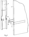
- a compact plate 3 has a milling 5 in the lower part with a dovetail cross section.
- the milling 5 extends over the entire length of the compact plate 3 or only over a section of the compact plate, as is indicated in FIG. 1 by the dashed lines.
- a profile 2 is composed of two sections 10 and 20, with one section 20 one upside down L-shaped cross section.
- the other section 10 connects centrally to the horizontal leg of section 20 and has a dovetail cross-section that can be inserted seamlessly into the milling 5 of the compact plate 3.
- the section 20 can be positively inserted into an incision 24 in a base body 4.
- This base body 4 is, for example, a U-shaped metal support, which is arranged vertically in a steel frame, which defines the outline of a house or which is attached to the wall of a building or a room as a substructure for the wall covering.
- the incision 24 is located in the two side walls 23 of the base body 4.
- the material of the profile 2 is generally different from the material of the compact plate 3, which consists of one or more resin-impregnated fiber layers which form the core of the compact plate.
- the two outer sides of this core are each covered with a decorative plate. Decorative layer coated.
- FIG 2 shows a detail and on an enlarged scale, the fastening system 1 with the profile 2 and the compact plate 3.
- the section 10 of the profile 2 is inserted.
- the outline or cross section of the section 10 is also dovetail-shaped and inserts without play.
- the milling 5 has a depth t which is in the range from one third to half the thickness d, cf. Figures 2 and 3a, the compact plate.
- the small depth of the milling 5 is possible because the core of the compact plate 3 has great strength, so that even such a small depth ensures a mechanically very stable connection of the profile 2 to the compact plate 3.
- the profile 2 is inserted with its portion 10 laterally into the milling 5.
- the length of the profile 2 can be chosen so that it extends over a partial length, the total length of a compact plate or over two or more compact plates.
- the profile 2 can also be connected to a base body or to a wall in a different way than shown in FIG. 1. For example, it is possible to screw section 20 of profile 2 to any number of fastening points with a wall or a base body. Due to the connection between profile 2 and the compact plate 3, similar to a tongue and groove connection, the assembly is largely stress-free if the cross sections are dimensioned correctly.
- an increase in the bending rigidity in the direction of the longitudinal axis of the profile (or milling) of the compact plate 3 perpendicular to its surface is obtained by connecting these two parts.
- the compact plate 3 can move freely in the direction of the longitudinal axis of the profile or the milling 5, so that differences in the thermal and hygroscopic effects of the different materials for the profile 2 and the compact plate 3 can be absorbed and compensated for.
- FIGS. 3a to 3d show different fastening systems, in which the compact plates and the profiles are adapted to one another.
- the depth of the milling 5 is one third of the thickness d of the compact plate 3.
- Figure 3b shows a fastening system 1, in which an end piece of a profile 14 is V-shaped and sections 11, 11 form the end sections of the V-shape.
- the opening angle ⁇ of the V shape is 50 up to 100 °.
- the milling 17, 17 consists of two cross sections 7, 7, which are arranged in mirror image to a perpendicular to the compact plate 3 and which are oblique to the surface of the Compact plate 3 run. These cross sections also form an angle of 50 to 100 ° with one another and take up the square-shaped sections 11, 11 of the profile 14.
- the depth of the milling 17, 17 is approximately half the thickness d / 2 of the compact plate 3.
- the end faces of the sections 11, 11 are oriented obliquely to the surface of the compact plate 3.
- the fastening system 1 according to FIG. 3c is formed from a compact plate 3 and a profile 15, the end piece of which has a shape similar to a two-pronged fork.
- the central piece 20 of the profile 15, which runs vertically in FIG. 3c, is adjoined by sections 12, 12 which run obliquely upwards and downwards.
- the end faces 21, 21 of the partial surface 12, 12 are oriented obliquely with respect to the surface of the compact plate 3.
- the middle piece 20 of the profile 15 ends with the surface of the compact plate 3.
- the angle enclosed by the two sections 12, 12 can be in the range from 60 to 120 °.
- a milling 18, 18 is provided therein from two cross sections 8, 8 arranged in mirror image to a perpendicular to the compact plate. These cross sections 8, 8 run obliquely and enclose the same angle as the sections 12, 12 with each other. The depth of the milling 18, 18 is half the thickness d / 2 of the compact plate 3.
- FIG. 3d A further fastening system 1 is shown in FIG. 3d, which is configured similarly to that according to FIG. 3c.
- a profile 16 has a fork-shaped, two-pronged shape with a vertical center piece 23 and adjoining sections 13, 13 which run obliquely upwards and downwards.
- the end faces 22, 22 of the sections 13, 13 are aligned parallel to the surface of the compact plate 3.
- a milling 19, 19 is adapted to the orientation of the sections 13, 13 of the profile 16.
- the milling 19, 19 has a depth equal to a third of the thickness d of the compact plate 3.
- the center piece 23 of the profile 16 lies against the surface of the plate 3.
- fastening system consisting of profile and compact plate also deviating from the shapes and cross sections shown in the exemplary embodiments without deviating from the subject matter of the invention.
- the fastening system according to the invention is not limited to the use of compact plates of the type described, rather it is also suitable for other plate materials.
Landscapes
- Engineering & Computer Science (AREA)
- Architecture (AREA)
- Civil Engineering (AREA)
- Structural Engineering (AREA)
- Finishing Walls (AREA)
Abstract
Description
Die Erfindung betrifft ein Befestigungssystem für Kompaktplatten aus einer oder mehreren miteinander heißverpreßten, mit Harz imprägnierten Faserschichten, die außen an zumindest einer Seite mit einer Dekorschicht beschichtet sind, zur unsichtbaren Montage auf einem Grundkörper.The invention relates to a fastening system for compact panels made of one or more fiber layers which are hot-pressed together and impregnated with resin and which are coated on the outside on at least one side with a decorative layer, for invisible mounting on a base body.
Der Aufbau von Kompaktplatten, insbesondere von sogenannten HPL (high pressure laminate)-Kompaktplatten, ist nach DIN 16926 bzw. ISO 4586 festgelegt. Unter den Begriff Kompaktplatten fallen auch solche Platten, die einen der DIN- oder ISO-Norm sehr ähnlichen Aufbau besitzen. Die Komponenten derartiger Kompaktplatten werden aus den gleichen Materialien in den gleichen Hochdruckpressen hergestellt wie alle HPL-Platten und enthalten, je nach Formungsverfahren, fallweise Klebeschichten. Die ein- bzw. beidseitige dekorative Farbgebung der Kompaktplatte kann auf einer glatten oder strukturierten Oberfläche vorgenommen werden.The structure of compact sheets, especially so-called HPL (high pressure laminate) compact sheets, is defined in accordance with DIN 16926 and ISO 4586. The term compact panels also includes panels that have a structure very similar to the DIN or ISO standard. The components of such compact sheets are made from the same materials in the same high-pressure presses as all HPL sheets and, depending on the molding process, contain adhesive layers from case to case. The decorative coloring of the compact panel on one or both sides can be carried out on a smooth or structured surface.
Der Kern von HPL-Kompaktplatten besitzt eine sehr große Festigkeit und kann daher große Kräfte aufnehmen, ohne zu Bruch zu gehen oder sich zu verformen.The core of HPL compact panels is very strong and can therefore absorb large forces without breaking or deforming.
Derartige Platten werden insbesondere für Fassaden- und Wandverkleidungen aufgrund ihrer hohen Witterungs- und Formbeständigkeit eingesetzt, wobei darauf geachtet wird, daß die Befestigung der Platten an einer Wand oder einem Grundkörper von außen her unsichtbar ist. Solche unsichtbaren Befestigungen werden bisher für HPL-Kompaktplatten in der Weise realisiert, daß diese Platten geklebt oder mittels Schrauben befestigt werden. Bei Schraubverbindungen erfolgen diese direkt mit den Kompaktplatten, wobei im allgemeinen die Dübel in den Platten stecken. Die Verbindung mit der dahinter liegenden Wand bzw. mit dem dahinter befindlichen Grundkörper geschieht über Bügel. Bei einer Wandbefestigung der Kompaktplatten werden im allgemeinen die Schraubverbindungen mit Hilfe von Dübeln in den Platten hergestellt. Dabei ist es wegen der hohen Biegesteifigkeit bei den Kompaktplatten erforderlich, abhängig von der Belastung und dem Format der Kompaktplatte, relativ viele Befestigungspunkte vorzusehen, wodurch die gesamte Montage vor Ort zeitaufwendig und dementsprechend teuer wird. Unterschiedliche Plattenformate, bei unsichtbar befestigten Kompaktplatten, erfordern meist komplizierte Bearbeitungsschritte auf der Baustelle oder zusätzliche Bearbeitungsschritte in der Werkhalle für die Vorbereitung der Kompaktplatten.Such panels are used in particular for facade and wall cladding due to their high weather and shape stability, care being taken to ensure that the panels are fastened is invisible from the outside on a wall or a body. Such invisible fastenings have so far been realized for HPL compact panels in such a way that these panels are glued or fastened by means of screws. In the case of screw connections, these are made directly with the compact panels, with the dowels generally being inserted in the panels. The connection to the wall behind or to the basic body located behind is made via brackets. When the compact panels are attached to the wall, the screw connections are generally made using dowels in the panels. It is necessary because of the high bending stiffness of the compact plates, depending on the load and the format of the compact plate, to provide a relatively large number of fastening points, as a result of which the entire assembly on site is time-consuming and accordingly expensive. Different panel formats, with invisibly attached compact panels, usually require complicated processing steps on the construction site or additional processing steps in the workshop to prepare the compact panels.
Zur Herstellung von Eckverbindungen in Holz und für die Linearführung von Schlitten oder dergleichen Maschinenteilen ist es bekannt, Nut- und Federverbindungen bzw. Führungsnuten und mit diesen im Eingriff befindliche Gleitstücke zu verwenden, die den gleichen Querschnitt wie die Führungsnut besitzen, und in diese eingepaßt sind.For the production of corner connections in wood and for the linear guidance of carriages or similar machine parts, it is known to use tongue and groove connections or guide grooves and slides in engagement therewith, which have the same cross-section as the guide groove and are fitted into them .
Aufgabe der Erfindung ist es, für Platten, die für witterungsfeste Verkleidungen verwendet werden, ein Befestigungssystem zu schaffen, bei dem die Platten über das Gesamtmaß ihres Formats befestigt werden können und eine weitgehend spannungsfreie Verbindung von Platten und dahinter liegender Wand oder eines Grundkörpers ermöglicht wird.The object of the invention is a for panels that are used for weatherproof cladding To create fastening system in which the plates can be fastened over the entire size of their format and a largely tension-free connection of plates and the wall or base body behind it is made possible.
Diese Aufgabe wird erfindungsgemäß in der Weise gelöst, daß das Befestigungssystem aus einem Profil besteht, das die Kompaktplatten und eine Wand bzw. einen Grundkörper miteinander verbindet, und daß in den dem Grundkörper zugewandten Seiten der Kompaktplatten Fräsungen angebracht sind, deren Querschnitte sich mit Teilstücken des Profils decken.This object is achieved in such a way that the fastening system consists of a profile that connects the compact plates and a wall or a base body, and that in the sides of the base plate facing the base body are milled, the cross-sections of which sections with the Profiles cover.
In Ausgestaltung der Erfindung weist die einzelne Fräsung eine Tiefe auf, die im Bereich von einem Drittel bis zur Hälfte der Dicke d der Kompaktplatte liegt und erstreckt sich die Fräsung über einen Teil oder über das Gesamtmaß der Kompaktplatte.In an embodiment of the invention, the individual milling has a depth that is in the range from one third to half the thickness d of the compact plate and the milling extends over part or over the entire dimension of the compact plate.
Die Erfindung wird in der Weise weitergestaltet, daß die Fräsung einen schwalbenschwanzförmigen Querschnitt aufweist und ein schwalbenschwanzförmiges Teilstück des Profils aufnimmt.The invention is further developed in such a way that the milling has a dovetail cross section and receives a dovetail section of the profile.
Die weitere Ausgestaltung der Erfindung ergibt sich aus den Merkmalen der Schutzansprüche 4 bis 12.The further embodiment of the invention results from the features of claims 4 to 12.
Mit der Erfindung werden die Vorteile erzielt, daß in Richtung der Längsachse des Profils die Kompaktplatten frei beweglich sind, so daß die wegen unterschiedlicher Materialien von Kompaktplatte und Wand bzw. Grundkörper auftretenden thermischen und hygroskopischen Unterschiede der Materialien aufgenommen und kompensiert werden können. Durch die Befestigung der Kompaktplatte auf dem Profil ergibt sich in Abhängigkeit von der Fräsung- und Profil-Dimensionierung sowie vom Profilmaterial eine Erhöhung der Biegesteifigkeit der Kombination Kompaktplatte - Profil, in Richtung der Längsachse des Profils, senkrecht zur Plattenoberfläche. Durch die richtige Dimensionierung wird die Verbindung Kompaktplatte - Profil - Wand bzw. - Grundkörper spannungsfrei gehalten.With the invention, the advantages are achieved that the compact plates are freely movable in the direction of the longitudinal axis of the profile, so that the thermal and hygroscopic differences in the materials occurring due to different materials of the compact plate and wall or base body are recorded and can be compensated. By attaching the compact plate to the profile, depending on the milling and profile dimensioning as well as the profile material, there is an increase in the bending stiffness of the combination compact plate - profile, in the direction of the longitudinal axis of the profile, perpendicular to the plate surface. Correct dimensioning keeps the connection between the compact panel - profile - wall or base body tension-free.
Die Erfindung wird anhand von zeichnerisch dargestellten Ausführungsbeispielen näher erläutert. Es zeigen:
- Fig. 1
- in perspektivischer Explosionsdarstellung einen Grundkörper, ein Profil sowie eine Kompaktplatte,
- Fig. 2
- ausschnittsweise die Verbindung einer Kompaktplatte mit einem Profil;
- Figuren 3a-3d
- schematisch verschiedene Profilformen in Verbindung mit Kompaktplatten.
- Fig. 1
- an exploded perspective view of a base body, a profile and a compact plate,
- Fig. 2
- sections of the connection of a compact plate with a profile;
- Figures 3a-3d
- schematically different profile shapes in connection with compact panels.
Eine Kompaktplatte 3 weist im unteren Teil eine Fräsung 5 mit einem schwalbenschwanzförmigen Querschnitt auf. Die Fräsung 5 erstreckt sich über die Gesamtlänge der Kompaktplatte 3 oder nur über einen Abschnitt der Kompaktplatte, wie dies in Figur 1 durch die gestrichelten Linien angedeutet ist. Ein Profil 2 ist aus zwei Teilstücken 10 und 20 zusammengesetzt, wobei das eine Teilstück 20 einen auf den Kopf gestellten L-förmigen Querschnitt aufweist. Das andere Teilstück 10 schließt mittig an den waagerechten Schenkel des Teilstücks 20 an und hat einen schwalbenschwanzförmigen Querschnitt, der nahtlos in die Fräsung 5 der Kompaktplatte 3 einschiebbar ist. Das Teilstück 20 ist in einen Einschnitt 24 eines Grundkörpers 4 formschlüssig einsetzbar. Dieser Grundkörper 4 ist beispielsweise ein U-förmiger Metallträger, der vertikal in einem Stahlgerüst angeordnet ist, das den Umriß eines Hauses festlegt oder der an der Wand eines Gebäudes oder eines Raumes als Unterbau für die Wandverkleidung befestigt ist. Der Einschnitt 24 befindet sich in den beiden Seitenwänden 23 des Grundkörpers 4.A compact plate 3 has a
Das Material des Profils 2 ist im allgemeinen anders als das Material der Kompaktplatte 3, die aus einer oder mehreren miteinander heißverpreßten, mit Harz imprägnierten Faserschichten besteht, die den Kern der Kompaktplatte bilden. Die beiden Außenseiten dieses Kerns sind jeweils mit einer Dekorplatte bez. Dekorschicht beschichtet.The material of the profile 2 is generally different from the material of the compact plate 3, which consists of one or more resin-impregnated fiber layers which form the core of the compact plate. The two outer sides of this core are each covered with a decorative plate. Decorative layer coated.
Figur 2 zeigt ausschnittsweise und im vergrößerten Maßstab das Befestigungssystem 1 mit dem Profil 2 und der Kompaktplatte 3. In die Fräsung 5, die, wie schon zuvor erwähnt wurde, einen schwalbenschwanzförmigen Querschnitt besitzt, ist das Teilstück 10 des Profils 2 eingesetzt. Der Umriß bzw. Querschnitt des Teilstücks 10 ist gleichfalls schwalbenschwanzförmig ausgebildet und fügt sich ohne Spiel ein. Die Fräsung 5 weist eine Tiefe t auf, die im Bereich von einem Drittel bis zur Hälfte der Dicke d, vgl. Figuren 2 und 3a, der Kompaktplatte liegt. Die geringe Tiefe der Fräsung 5 ist möglich, da der Kern der Kompaktplatte 3 große Festigkeit besitzt, so daß schon eine so geringe Tiefe eine mechanisch sehr stabile Verbindung des Profils 2 mit der Kompaktplatte 3 gewährleistet. Das Profil 2 wird mit seinem Teilstück 10 während der Montage seitlich in die Fräsung 5 eingeschoben. Die Länge des Profils 2 kann so gewählt werden, daß sie sich über eine Teillänge, die Gesamtlänge einer Kompaktplatte oder über zwei oder mehr Kompaktplatten erstreckt. Das Profil 2 kann auch auf andere Weise, als in Figur 1 dargestellt, mit einem Grundkörper bzw. mit einer Wand verbunden werden. So ist es beispielsweise möglich, das Teilstück 20 des Profils 2 an beliebig vielen Befestigungspunkten mit einer Wand oder einem Grundkörper zu verschrauben. Durch die Verbindung zwischen Profil 2 und der Kompaktplatte 3, ähnlich einer Nut-Federverbindung, erfolgt das Zusammenfügen bei entsprechend richtiger Dimensionierung der Querschnitte weitgehend spannungsfrei. Abhängig von der Dimensionierung der Fräsung 5 und dem Profil 2 wird durch die Verbindung dieser beiden Teile eine Erhöhung der Biegesteifigkeit in Richtung der Längsachse des Profils (oder Fräsung) der Kompaktplatte 3 senkrecht zu ihrer Oberfläche erhalten. In Richtung der Längsachse des Profils bzw. der Fräsung 5 kann sich die Kompaktplatte 3 frei bewegen, so daß Unterschiede in den thermischen und hygroskopischen Wirkungen der unterschiedlichen Materialien für das Profil 2 und die Kompaktplatte 3 aufgenommen und ausgeglichen werden können.Figure 2 shows a detail and on an enlarged scale, the fastening system 1 with the profile 2 and the compact plate 3. In the
Bei diesem Befestigungssystem können abweichende Formate der Kompaktplatten vor der Montage problemlos berücksichtigt werden, indem beispielsweise die Längen der Profile auf die abweichenden Maße der einen oder anderen Kompaktplatte gekürzt werden. Dadurch können die Bearbeitungs- und Montagezeiten bzw. -kosten niedriggehalten werden, im Vergleich hierzu sind die gängigen Klebetechniken für Kompaktplatten kompliziert, da sie von der Temperatur und der Feuchtigkeit während der Montage abhängen und außerdem etliche Vorarbeiten, wie Entfetten, Grund- und Klebeschichten anbringen, erfordern. Die üblichen Schraubbbefestigungen sind arbeitsaufwendig, da sowohl das Profil und die Kompaktplatte miteinander verschraubt werden müssen als auch das Profil mit der Wand bzw. dem Grundkörper.With this fastening system, different formats of the compact panels can be easily taken into account before assembly, for example by shortening the lengths of the profiles to the different dimensions of one or the other compact panel. This means that processing and assembly times and costs can be kept low.Comparison to this, the common adhesive techniques for compact panels are complicated because they depend on the temperature and humidity during assembly and also do a lot of preparatory work such as degreasing, base and adhesive layers , require. The usual screw fastenings are labor-intensive, since both the profile and the compact plate have to be screwed together, as well as the profile with the wall or the base body.
In den Figuren 3a bis 3d sind verschiedene Befestigungssysteme dargestellt, bei denen jeweils die Kompaktplatten und die Profile aneinander angepaßt sind. Bei dem Befestigungssystem 1, das in Figur 3a schematisch gezeigt ist, beträgt die Tiefe der Fräsung 5 ein Drittel der Dicke d der Kompaktplatte 3. Es handelt sich hierbei um die schon anhand der Figuren 1 und 2 beschriebene schwalbenschwanzförmige Fräsung 5 mit dem Profil 2, dessen Teilstück 10 gleichfalls einen schwalbenschwanzförmigen Querschnitt besitzt und spielfrei in die Fräsung 5 eingeschoben ist.FIGS. 3a to 3d show different fastening systems, in which the compact plates and the profiles are adapted to one another. In the fastening system 1, which is shown schematically in FIG. 3a, the depth of the
Figur 3b zeigt ein Befestigungssystem 1, bei dem ein Endstück eines Profils 14 V-förmig ausgebildet ist und Teilstücke 11, 11 die Endabschnitte der V-Form bilden. Der Öffnungswinkel α der V-Form beträgt 50 bis 100°. In der Kompaktplatte 3 befindet sich eine entsprechende Fräsung 17, 17 für die Aufnahme des V-förmigen Profils 14. Die Fräsung 17, 17 besteht aus zwei spiegelbildlich zu einer Senkrechten auf die Kompaktplatte 3 angeordneten Querschnitten 7, 7, die schräg zu der Oberfläche der Kompaktplatte 3 verlaufen. Diese Querschnitte schließen gleichfalls einen Winkel von 50 bis 100° miteinander ein und nehmen die vierkantförmigen Teilstücke 11, 11 des Profils 14 auf. Die Tiefe der Fräsung 17, 17 beträgt etwa die halbe Dicke d/2 der Kompaktplatte 3. Die Stirnflächen der Teilstücke 11, 11 sind schräg zu der Oberfläche der Kompaktplatte 3 ausgerichtet.Figure 3b shows a fastening system 1, in which an end piece of a
Das Befestigungssystem 1 nach Figur 3c wird aus einer Kompaktplatte 3 und einem Profil 15 gebildet, dessen Endstück eine Gestalt ähnlich einer zweizinkigen Gabel hat. An das in Figur 3c senkrecht verlaufende Mittelstück 20 des Profils 15 schließen schräg nach oben und unten verlaufende Teilstücke 12, 12 an. Die Stirnflächen 21, 21 der Teilfläche 12, 12 sind gegenüber der Oberfläche der Kompaktplatte 3 schräg ausgerichtet. Das Mittelstück 20 des Profils 15 schließt mit der Oberfläche der Kompaktplatte 3 ab. Der von den beiden Teilstücken 12, 12 eingeschlossene Winkel kann im Bereich von 60 bis 120° liegen. Zum Verbinden dieses Profils 15 mit der Kompaktplatte 3 ist in dieser eine Fräsung 18, 18 aus zwei spiegelbildlich zu einer Senkrechten auf die Kompaktplatte angeordneten Querschnitten 8, 8 vorgesehen. Diese Querschnitte 8, 8 verlaufen schräg und schließen den gleichen Winkel wie die Teilstücke 12, 12 miteinander ein. Die Tiefe der Fräsung 18, 18 beträgt die halbe Dicke d/2 der Kompaktplatte 3.The fastening system 1 according to FIG. 3c is formed from a compact plate 3 and a
In Figur 3d ist ein weiteres Befestigungssystem 1 dargestellt, das ähnlich demjenigen nach Figur 3c ausgestaltet ist. Ein Profil 16 hat eine gabelförmige, zweizinkige Gestalt mit einem senkrechten Mittelstück 23 und daran anschließenden, nach oben und nach unten schräg verlaufenden Teilstücken 13, 13. Die Stirnflächen 22, 22 der Teilstücke 13, 13 sind parallel zu der Oberfläche der Kompaktplatte 3 ausgerichtet. Eine Fräsung 19, 19 ist an die Orientierung der Teilstücke 13, 13 des Profils 16 angepaßt. Die Fräsung 19, 19 besitzt eine Tiefe gleich einem Drittel der Dicke d der Kompaktplatte 3. Das Mittelstück 23 des Profils 16 liegt an der Oberfläche der Platte 3 an.A further fastening system 1 is shown in FIG. 3d, which is configured similarly to that according to FIG. 3c. A
Es liegt im Rahmen des Fachwissens des Fachmanns, das Befestigungssystem aus Profil und Kompaktplatte auch abweichend von den in den Ausführungsbeispielen gezeigten Formen und Querschnitten auszugestalten, ohne daß von dem Gegenstand der Erfindung abgewichen wird. Das Befestigungssystem nach der Erfindung ist nicht auf den Einsatz von Kompaktplatten der beschriebenen Art beschränkt, vielmehr ist es auch für andere Plattenmaterialien geeignet.It is within the specialist knowledge of the person skilled in the art to design the fastening system consisting of profile and compact plate also deviating from the shapes and cross sections shown in the exemplary embodiments without deviating from the subject matter of the invention. The fastening system according to the invention is not limited to the use of compact plates of the type described, rather it is also suitable for other plate materials.
Claims (12)
Applications Claiming Priority (2)
| Application Number | Priority Date | Filing Date | Title |
|---|---|---|---|
| DE9416917U DE9416917U1 (en) | 1994-10-20 | 1994-10-20 | Fastening system for compact panels |
| DE9416917U | 1994-10-20 |
Publications (2)
| Publication Number | Publication Date |
|---|---|
| EP0708213A1 true EP0708213A1 (en) | 1996-04-24 |
| EP0708213B1 EP0708213B1 (en) | 2000-05-03 |
Family
ID=6915132
Family Applications (1)
| Application Number | Title | Priority Date | Filing Date |
|---|---|---|---|
| EP95116076A Expired - Lifetime EP0708213B1 (en) | 1994-10-20 | 1995-10-12 | Fixing system with compact panels |
Country Status (2)
| Country | Link |
|---|---|
| EP (1) | EP0708213B1 (en) |
| DE (2) | DE9416917U1 (en) |
Cited By (8)
| Publication number | Priority date | Publication date | Assignee | Title |
|---|---|---|---|---|
| EP0943041A1 (en) * | 1996-09-05 | 1999-09-22 | James Hardie Research Pty. Ltd. | An improved cladding board mounting system |
| DE102005019977A1 (en) * | 2005-04-27 | 2006-11-09 | Deutsche Steinzeug Cremer & Breuer Ag | Building facade has support frame defining ventilation space for ceramic panels attached by fixings in grooves in rear panel faces |
| WO2007032592A1 (en) | 2005-09-16 | 2007-03-22 | Lg Chem, Ltd. | Panel installation set and method of installing panel using the same |
| US7993570B2 (en) | 2002-10-07 | 2011-08-09 | James Hardie Technology Limited | Durable medium-density fibre cement composite |
| US7998571B2 (en) | 2004-07-09 | 2011-08-16 | James Hardie Technology Limited | Composite cement article incorporating a powder coating and methods of making same |
| ITMS20110001A1 (en) * | 2011-01-28 | 2012-07-29 | Cesare Ferrari | METAL OR PLASTIC ELEMENT, COMPOSED OF A SINGLE PIECE, FOR ASSEMBLY, OF COVERING PANELS. |
| US8769901B2 (en) | 2010-05-28 | 2014-07-08 | The Diller Corporation | Cladding system for building laminates |
| US8993462B2 (en) | 2006-04-12 | 2015-03-31 | James Hardie Technology Limited | Surface sealed reinforced building element |
Families Citing this family (7)
| Publication number | Priority date | Publication date | Assignee | Title |
|---|---|---|---|---|
| AT404746B (en) * | 1995-05-23 | 1999-02-25 | Falb Karl | PLATE FASTENING |
| DE19753768A1 (en) | 1997-12-04 | 1999-06-10 | Trespa Int Bv | Mounting system for panels for facade cladding of buildings |
| DE10022615C2 (en) * | 2000-04-18 | 2002-07-18 | Klaus Winter | Ventilated facade cladding |
| CZ20032808A3 (en) | 2001-04-03 | 2004-04-14 | James Hardie Research Pty Limited | Reinforced fiber cement article, and methods of making and installing thereof |
| DE10163508A1 (en) | 2001-12-21 | 2003-07-03 | Trespa Int Bv | Panel mounting system for creating a wall |
| US8281535B2 (en) | 2002-07-16 | 2012-10-09 | James Hardie Technology Limited | Packaging prefinished fiber cement articles |
| DK1534511T3 (en) | 2002-07-16 | 2012-07-09 | Hardie James Technology Ltd | PACKAGING FOR PREFABRICATED FIBER CEMENT PRODUCTS |
Citations (5)
| Publication number | Priority date | Publication date | Assignee | Title |
|---|---|---|---|---|
| FR1530114A (en) * | 1966-06-30 | 1968-06-21 | S Guffanti & Ratti Di Raineri | Process for fixing coating strips on walls or walls and elements for its implementation |
| DE2364224A1 (en) * | 1973-12-22 | 1975-11-13 | Guenther Dipl Ing Koch | Plastic concrete slab curtain wall system - with undercut-edged slab groove engaging stem of diverging-armed carrier batten |
| DE2460880A1 (en) * | 1974-12-21 | 1976-06-24 | Horst Hahn | Curtain-wall panel or other building element anchorage - involving panel recess, and screw or similar base attachment |
| EP0081147A1 (en) * | 1981-12-04 | 1983-06-15 | Hoechst Aktiengesellschaft | Decorative moulded panel, method of production and use |
| WO1993001418A1 (en) * | 1991-07-11 | 1993-01-21 | ISOVOLTA Österreichische Isolierstoffwerke Aktiengesellschaft | Device for the concealed hanging of panels from load-bearing structures |
-
1994
- 1994-10-20 DE DE9416917U patent/DE9416917U1/en not_active Expired - Lifetime
-
1995
- 1995-10-12 EP EP95116076A patent/EP0708213B1/en not_active Expired - Lifetime
- 1995-10-12 DE DE59508257T patent/DE59508257D1/en not_active Expired - Fee Related
Patent Citations (5)
| Publication number | Priority date | Publication date | Assignee | Title |
|---|---|---|---|---|
| FR1530114A (en) * | 1966-06-30 | 1968-06-21 | S Guffanti & Ratti Di Raineri | Process for fixing coating strips on walls or walls and elements for its implementation |
| DE2364224A1 (en) * | 1973-12-22 | 1975-11-13 | Guenther Dipl Ing Koch | Plastic concrete slab curtain wall system - with undercut-edged slab groove engaging stem of diverging-armed carrier batten |
| DE2460880A1 (en) * | 1974-12-21 | 1976-06-24 | Horst Hahn | Curtain-wall panel or other building element anchorage - involving panel recess, and screw or similar base attachment |
| EP0081147A1 (en) * | 1981-12-04 | 1983-06-15 | Hoechst Aktiengesellschaft | Decorative moulded panel, method of production and use |
| WO1993001418A1 (en) * | 1991-07-11 | 1993-01-21 | ISOVOLTA Österreichische Isolierstoffwerke Aktiengesellschaft | Device for the concealed hanging of panels from load-bearing structures |
Cited By (14)
| Publication number | Priority date | Publication date | Assignee | Title |
|---|---|---|---|---|
| EP0943041A4 (en) * | 1996-09-05 | 1999-12-01 | James Hardie Res Pty Ltd | An improved cladding board mounting system |
| US6226947B1 (en) | 1996-09-05 | 2001-05-08 | James Hardie Research Pty Limited | Cladding board mounting system |
| EP0943041A1 (en) * | 1996-09-05 | 1999-09-22 | James Hardie Research Pty. Ltd. | An improved cladding board mounting system |
| US7993570B2 (en) | 2002-10-07 | 2011-08-09 | James Hardie Technology Limited | Durable medium-density fibre cement composite |
| US7998571B2 (en) | 2004-07-09 | 2011-08-16 | James Hardie Technology Limited | Composite cement article incorporating a powder coating and methods of making same |
| DE102005019977A1 (en) * | 2005-04-27 | 2006-11-09 | Deutsche Steinzeug Cremer & Breuer Ag | Building facade has support frame defining ventilation space for ceramic panels attached by fixings in grooves in rear panel faces |
| DE102005019977B4 (en) * | 2005-04-27 | 2007-12-27 | Deutsche Steinzeug Cremer & Breuer Ag | Facade system made of ceramic façade panels for use as a ventilated façade on a supporting building wall |
| EP1924753A1 (en) * | 2005-09-16 | 2008-05-28 | LG Chem, Ltd. | Panel installation set and method of installing panel using the same |
| EP1924753A4 (en) * | 2005-09-16 | 2010-04-28 | Lg Chemical Ltd | Panel installation set and method of installing panel using the same |
| WO2007032592A1 (en) | 2005-09-16 | 2007-03-22 | Lg Chem, Ltd. | Panel installation set and method of installing panel using the same |
| US8993462B2 (en) | 2006-04-12 | 2015-03-31 | James Hardie Technology Limited | Surface sealed reinforced building element |
| US8769901B2 (en) | 2010-05-28 | 2014-07-08 | The Diller Corporation | Cladding system for building laminates |
| US8991127B2 (en) | 2010-05-28 | 2015-03-31 | The Diller Corporation | Cladding system for building laminates |
| ITMS20110001A1 (en) * | 2011-01-28 | 2012-07-29 | Cesare Ferrari | METAL OR PLASTIC ELEMENT, COMPOSED OF A SINGLE PIECE, FOR ASSEMBLY, OF COVERING PANELS. |
Also Published As
| Publication number | Publication date |
|---|---|
| EP0708213B1 (en) | 2000-05-03 |
| DE59508257D1 (en) | 2000-06-08 |
| DE9416917U1 (en) | 1994-12-01 |
Similar Documents
| Publication | Publication Date | Title |
|---|---|---|
| EP0708213B1 (en) | Fixing system with compact panels | |
| DE3402923A1 (en) | COMPOSITE PLATE AND METHOD FOR PRODUCING A COMPOSITE PLATE | |
| DE19846599A1 (en) | Prefabricated partition wall units incorporate horizontal and vertical channels for passage of cables and services | |
| DE4031176A1 (en) | DOOR LEAF AND METHOD FOR PRODUCING SUCH A DOOR LEAF | |
| DE3229262A1 (en) | Wooden structural element in the form of a panel | |
| WO2008092699A1 (en) | Inspection device, in particular inspection cover | |
| WO2009006926A1 (en) | 45° wall panel concept | |
| DE3224883A1 (en) | Method for manufacturing a housing frame with rounded corners, in particular for radio and television sets, and housing frame manufactured by this method | |
| EP0249085A2 (en) | Post profile developed as lightweight partition profile | |
| EP3015614A1 (en) | Wall panel for dry construction consisting of a wooden material and wall structure and manufacturing method | |
| DE4127636A1 (en) | Bearer-plate door panel - has frame components along long sides, top and bottom sections, and profile bars | |
| DE4010920A1 (en) | Panel for fire protection door - has sheet metal cover extended to reinforce tongue and groove joints between panels | |
| EP0898086A2 (en) | Fastening element | |
| DE19835106B4 (en) | Corner protection rail for lightweight panels | |
| DE2501330B2 (en) | Wall with a supporting framework composed of rod-shaped structural elements | |
| DE2252501A1 (en) | TABLE-SHAPED COMPOSITE ELEMENT | |
| DE3702298C2 (en) | ||
| DE2825914A1 (en) | Layered panelled and filled door - has inside frame piece with spacer base and protruding head | |
| AT507180B1 (en) | CONSTRUCTION CONSTRUCTION WITH ELEMENTALLY MOUNTED WEARING ELEMENTS | |
| DE3600933A1 (en) | Dismantleable free-standing wall, in particular for exhibitions | |
| DE8519520U1 (en) | Support rod for double-shell lightweight interior walls with high sound insulation | |
| DE2905027A1 (en) | ROOM INTERIOR WALL AND METHOD OF MANUFACTURING THE SAME | |
| EP0109968B1 (en) | Shelving unit made of wood | |
| DE202015009133U1 (en) | Set for making a lining of an interior corner | |
| EP0496020A1 (en) | Double panel postless wall assembly |
Legal Events
| Date | Code | Title | Description |
|---|---|---|---|
| PUAI | Public reference made under article 153(3) epc to a published international application that has entered the european phase |
Free format text: ORIGINAL CODE: 0009012 |
|
| AK | Designated contracting states |
Kind code of ref document: A1 Designated state(s): BE DE FR GB NL |
|
| 17P | Request for examination filed |
Effective date: 19961024 |
|
| RAP1 | Party data changed (applicant data changed or rights of an application transferred) |
Owner name: TRESPA INTERNATIONAL B.V. |
|
| 17Q | First examination report despatched |
Effective date: 19981113 |
|
| GRAG | Despatch of communication of intention to grant |
Free format text: ORIGINAL CODE: EPIDOS AGRA |
|
| RTI1 | Title (correction) |
Free format text: FIXING SYSTEM WITH COMPACT PANELS |
|
| GRAG | Despatch of communication of intention to grant |
Free format text: ORIGINAL CODE: EPIDOS AGRA |
|
| GRAH | Despatch of communication of intention to grant a patent |
Free format text: ORIGINAL CODE: EPIDOS IGRA |
|
| GRAH | Despatch of communication of intention to grant a patent |
Free format text: ORIGINAL CODE: EPIDOS IGRA |
|
| GRAA | (expected) grant |
Free format text: ORIGINAL CODE: 0009210 |
|
| AK | Designated contracting states |
Kind code of ref document: B1 Designated state(s): BE DE FR GB NL |
|
| REF | Corresponds to: |
Ref document number: 59508257 Country of ref document: DE Date of ref document: 20000608 |
|
| ET | Fr: translation filed | ||
| GBT | Gb: translation of ep patent filed (gb section 77(6)(a)/1977) |
Effective date: 20000706 |
|
| PLBE | No opposition filed within time limit |
Free format text: ORIGINAL CODE: 0009261 |
|
| STAA | Information on the status of an ep patent application or granted ep patent |
Free format text: STATUS: NO OPPOSITION FILED WITHIN TIME LIMIT |
|
| 26N | No opposition filed | ||
| REG | Reference to a national code |
Ref country code: GB Ref legal event code: IF02 |
|
| PGFP | Annual fee paid to national office [announced via postgrant information from national office to epo] |
Ref country code: BE Payment date: 20020830 Year of fee payment: 8 |
|
| PGFP | Annual fee paid to national office [announced via postgrant information from national office to epo] |
Ref country code: FR Payment date: 20021009 Year of fee payment: 8 |
|
| PGFP | Annual fee paid to national office [announced via postgrant information from national office to epo] |
Ref country code: NL Payment date: 20021018 Year of fee payment: 8 |
|
| PGFP | Annual fee paid to national office [announced via postgrant information from national office to epo] |
Ref country code: GB Payment date: 20021025 Year of fee payment: 8 |
|
| PG25 | Lapsed in a contracting state [announced via postgrant information from national office to epo] |
Ref country code: GB Free format text: LAPSE BECAUSE OF NON-PAYMENT OF DUE FEES Effective date: 20031012 |
|
| PG25 | Lapsed in a contracting state [announced via postgrant information from national office to epo] |
Ref country code: BE Free format text: LAPSE BECAUSE OF NON-PAYMENT OF DUE FEES Effective date: 20031031 |
|
| PGFP | Annual fee paid to national office [announced via postgrant information from national office to epo] |
Ref country code: DE Payment date: 20031031 Year of fee payment: 9 |
|
| BERE | Be: lapsed |
Owner name: *TRESPA INTERNATIONAL B.V. Effective date: 20031031 |
|
| PG25 | Lapsed in a contracting state [announced via postgrant information from national office to epo] |
Ref country code: NL Free format text: LAPSE BECAUSE OF NON-PAYMENT OF DUE FEES Effective date: 20040501 |
|
| GBPC | Gb: european patent ceased through non-payment of renewal fee |
Effective date: 20031012 |
|
| PG25 | Lapsed in a contracting state [announced via postgrant information from national office to epo] |
Ref country code: FR Free format text: LAPSE BECAUSE OF NON-PAYMENT OF DUE FEES Effective date: 20040630 |
|
| NLV4 | Nl: lapsed or anulled due to non-payment of the annual fee |
Effective date: 20040501 |
|
| REG | Reference to a national code |
Ref country code: FR Ref legal event code: ST |
|
| PG25 | Lapsed in a contracting state [announced via postgrant information from national office to epo] |
Ref country code: DE Free format text: LAPSE BECAUSE OF NON-PAYMENT OF DUE FEES Effective date: 20050503 |