EP0709543B1 - Downhole casing filling and circulating apparatus and method - Google Patents
Downhole casing filling and circulating apparatus and method Download PDFInfo
- Publication number
- EP0709543B1 EP0709543B1 EP95307696A EP95307696A EP0709543B1 EP 0709543 B1 EP0709543 B1 EP 0709543B1 EP 95307696 A EP95307696 A EP 95307696A EP 95307696 A EP95307696 A EP 95307696A EP 0709543 B1 EP0709543 B1 EP 0709543B1
- Authority
- EP
- European Patent Office
- Prior art keywords
- casing
- seal
- body member
- fluid
- pressure relief
- Prior art date
- Legal status (The legal status is an assumption and is not a legal conclusion. Google has not performed a legal analysis and makes no representation as to the accuracy of the status listed.)
- Expired - Lifetime
Links
Images


Classifications
-
- E—FIXED CONSTRUCTIONS
- E21—EARTH DRILLING; MINING
- E21B—EARTH DRILLING, e.g. DEEP DRILLING; OBTAINING OIL, GAS, WATER, SOLUBLE OR MELTABLE MATERIALS OR A SLURRY OF MINERALS FROM WELLS
- E21B21/00—Methods or apparatus for flushing boreholes, e.g. by use of exhaust air from motor
- E21B21/10—Valve arrangements in drilling-fluid circulation systems
- E21B21/106—Valve arrangements outside the borehole, e.g. kelly valves
-
- E—FIXED CONSTRUCTIONS
- E21—EARTH DRILLING; MINING
- E21B—EARTH DRILLING, e.g. DEEP DRILLING; OBTAINING OIL, GAS, WATER, SOLUBLE OR MELTABLE MATERIALS OR A SLURRY OF MINERALS FROM WELLS
- E21B33/00—Sealing or packing boreholes or wells
- E21B33/10—Sealing or packing boreholes or wells in the borehole
- E21B33/12—Packers; Plugs
- E21B33/126—Packers; Plugs with fluid-pressure-operated elastic cup or skirt
-
- E—FIXED CONSTRUCTIONS
- E21—EARTH DRILLING; MINING
- E21B—EARTH DRILLING, e.g. DEEP DRILLING; OBTAINING OIL, GAS, WATER, SOLUBLE OR MELTABLE MATERIALS OR A SLURRY OF MINERALS FROM WELLS
- E21B34/00—Valve arrangements for boreholes or wells
- E21B34/06—Valve arrangements for boreholes or wells in wells
Definitions
- the present invention relates to a method and apparatus for filling and circulating fluid through a well casing string as it is being run into a well bore, and for preventing spillage of the fluid when casing joints are added to the string or the filling and circulating apparatus is otherwise removed from the casing string.
- a well bore is drilled into one or more subterranean formations or zones containing oil and/or gas to be produced.
- the well bore is typically drilled utilizing a drilling rig which has a rotary table on its floor to rotate a pipe string during drilling and other operations.
- the drilling rig may also have a top drive mechanism for rotating the pipe string which is integral with the travelling block of the rig in addition to or instead of a rotary table.
- drilling fluid also called drilling mud
- drilling fluid is circulated through the well bore by pumping it down the drill string, through the drill bit and upwardly back to the surface through the annulus between the walls of the well bore and the drill string.
- the circulation of the drilling fluid functions to lubricate the drill bit, remove cuttings from the well bore as they are produced and to exert hydrostatic pressure on pressurized fluid containing formations penetrated by the well bore whereby blow-outs are prevented.
- the drill string is removed therefrom and a string of casing is run thereinto while maintaining sufficient drilling fluid in the well bore to prevent blow-outs, etc.
- casing running operations i.e., the lowering of a casing string into the well bore
- the casing is usually washed free by circulating a fluid, usually drilling fluid, down the casing and through the lower end thereof to wash sand or other debris away from the casing.
- the casing string must be kept filled with fluid to prevent excessive fluid pressure differentials across the casing string and to prevent blow-outs.
- fluid is added to the casing string after each additional casing joint is added to the string and the string is lowered into the well bore.
- the filling and circulating device must be removed from the casing string and reinstalled in the top of the casing joint added thereto. Because the fluid pressure inside the casing string is often greater than the fluid pressure within the filling and circulating device, when the device is removed from the casing string the ensuing pressure release often causes fluid to be spilled on the rig floor which produces a safety hazard to rig personnel.
- the fluid pressure differential between the filling and circulating device and the casing string is brought about by a check valve included in the device to prevent back-flow of fluid as the casing string is lowered into the well bore.
- the present invention provides an improved casing filling and circulating apparatus and method of utilizing such apparatus during the construction of a well which meet or reduce the shortcomings of the prior art.
- the improved casing filling and circulating apparatus of the invention comprises a tubular connector; a tubular pressure relief seal body member connected to an end of said connector; pressure relief seal means connected to said pressure relief seal body member for relieving pressure from said casing; a tubular casing seal body member connected to said pressure relief seal body member; check valve means connected to the interior of said casing seal body member for preventing spillage and for preventing fluid back-flow through said casing filling and circulating apparatus except when said pressure relief seal means permit such back flow; casing seal means connected to the exterior of said casing seal body member for sealingly engaging the interior of said casing string when inserted thereinto; and a tubular guide nose member connected to said casing seal body member, characterised in that said tubular pressure relief seal body member has an upper cylindrical portion connected to an enlarged lower cylindrical portion by a tapered connecting portion, said upper cylindrical portion and
- the invention also provides a method of filling and circulating fluid through a casing string comprised of a plurality of casing joints, while running the casing string into a well bore and preventing spillage of the fluid when casing joints are added to the casing string using a casing filling and circulating apparatus having a flow passage therethrough in fluid communication with fluid pumping equipment; which method comprises the steps of:
- the check valve means preferably comprises a poppet valve support and guide member disposed within said interior bore of said casing seal body member; a poppet valve adapted to seal against the interior surfaces of said tapered connecting portion of said pressure relief seal body member above said lateral port therein slidably engaged with said support and guide member; and spring means for biasing said poppet valve towards said pressure relief seal body member disposed between said poppet valve and said support and guide member.
- the casing seal means preferably comprises an annular centering member retained on the exterior surface of said casing seal body member; an annular elastomeric back-up member retained on the exterior surface of said casing seal body member; and an annular elastomeric cup seal member for sealingly engaging said casing retained on said exterior surface of said casing seal body member.
- the casing filling and circulating apparatus is caused to seal within said top casing joint of said casing string when fluid is pumped through said apparatus in accordance with step (b) by providing a casing seal means on an exterior surface of said apparatus positioned so that it is in sealing contact with said casing joint. It is also preferred for the pressurized fluid trapped within said casing to be relieved therefrom in accordance with step (e) by providing a pressure relief seal means within said filling and circulating apparatus which causes said pressurized fluid to be relieved from said casing by back-flow through said flow passage of said apparatus.
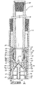
- FIG. 1 is a side cross-sectional view of a top part of one embodiment of casing filling and circulating tool of the present invention, inserted in a casing string.
- FIG. 2 is a side cross-sectional view of the bottom part of the tool of FIG. 1.
- FIG. 3 is side cross-sectional view of the top part of the tool of FIG. 1, but showing the tool during the pumping of drilling fluid therethrough.
- FIG. 4 is a side cross-sectional view of the bottom part of the tool of FIG. 3.
- FIGS. 1 and 2 the improved casing filling and circulating apparatus of the present invention is illustrated and generally designated by the numeral 10.
- the apparatus 10 is shown inserted into the top open end of a casing joint 12 having a casing collar 14 threadedly connected thereto which is a part of a casing string prior to introducing fluid into the casing string by way of the apparatus 10.
- the filling and circulating apparatus 10 is comprised of a tubular fluid conducting connector 16, a tubular pressure relief seal body member 18 connected to the lower end of the connector 16, a pressure relief seal assembly 20 connected to the pressure relief seal body member 18, a tubular casing seal body member 22 connected to the pressure relief body member 20, a check valve assembly 24 connected to the interior of the casing seal body member 22, a casing seal assembly 26 connected to the exterior of the casing seal body member 22 and a tubular guide nose member 28 connected to the lower end of the casing seal body member 22.
- the tubular connector 16 is threadedly connected at its top end to a fluid discharge coupling (not shown) which is attached to the traveling block or top drive of a drilling rig.
- a casing elevator (not shown) is also attached to the traveling block or top drive for removable attachment to a casing joint so that the casing joint can be connected to a casing string and the casing string can be lowered into the well bore, etc.
- the filling and circulating apparatus 10 is inserted into the upper open end of the joint as illustrated in the drawings.
- the elongated tubular connector 16 includes a first threaded bore 30 for releasably engaging the above mentioned fluid coupling, and a second threaded bore 32 for threadedly engaging the pressure relief seal body member 18.
- a conventional O-ring 34 is disposed between the connecting member 16 and the pressure relief seal body member 18 to prevent leakage therebetween.
- the pressure relief seal body member 18 is comprised of an annular member having an upper cylindrical portion 36 connected to an enlarged lower cylindrical portion 40 by a tapered connecting portion 38.
- a plurality of lateral ports 42 are disposed in the upper cylindrical portion 36 of the body member 18, and a plurality of lateral ports 44 are disposed in the tapered connecting portion 38 thereof.
- the upper cylindrical portion 36 of the member 18 includes an external threaded portion 46 for connecting the body member 18 to the threaded bore 32 of the connector 16.
- the lower enlarged cylindrical portion 40 of the body member 18 includes an internal threaded bore 48 for connection to the casing seal body member 22.
- the pressure relief seal assembly 20 connected to the pressure relief seal body 18 is comprised of a cup seal member 50 for providing a one way seal in an annular passageway and a housing, generally designated by the numeral 56, which will be described further hereinbelow.
- the cup seal member 50 is retained on the external surface of the cylindrical portion 36 of the body member 18 above the lateral ports 42 therein.
- the cup seal member 50 includes a back-up ring 52 which sealingly engages the external surface of the cylindrical portion 36 of the body member 18 by means of an O-ring seal 54 disposed in a groove in the back-up member 52.
- the housing 56 of the pressure relief seal assembly 20 is comprised of an inner cylindrical wall 58 and an outer cylindrical wall 60.
- the inner cylindrical wall 58 is sealingly attached to the lower end of upper cylindrical portion 36 of the body member 18 below the lateral ports 42 therein.
- An O-ring seal 61 is disposed between the inner wall 58 and the body member 18 at the connection therebetween.
- the inner wall 58 forms an inner annular passageway 62 within which the cup seal member 50 is disposed.
- the outer wall 60 of the housing 56 is attached to the enlarged lower cylindrical portion 40 of the body member 18 at its lower end, to the upper end of the inner wall 58 and to a lower end portion of the connector 16.
- An O-ring seal 64 is disposed between the outer wall 60 and the connector 16
- an O-ring seal 66 is disposed between the outer wall 60 and the enlarged lower cylindrical portion 40 of the body member 18.
- the outer wall 60 of the housing 56 forms a second annular passageway 68 between the inner and outer walls 58 and 60.
- the lateral ports 44 of the tapered connecting portion 38 of the body member 18 communicate with the annular passageway 68
- the inner wall 58 includes a plurality of lateral ports 70 disposed in the upper end portion thereof which communicate the annular passageway 62 containing the cup seal member 50 with the annular passageway 68.
- the lateral ports 42 in the upper cylindrical member 36 of the body member 18 communicate with the annular passageway 62.
- the interior of the body member 18 below the valve 94 of the check valve assembly 24 is communicated with the annular passageway 68 by the ports 44.
- the annular passageway 68 is communicated with the annular passageway 62 by the ports 70 in the inner wall 58, and the annular passageway 62 is communicated with the interior of the upper cylindrical portion 36 of the body member 18 above the valve 94 of the check valve assembly 24 by the ports 42.
- an upper threaded recessed portion of the casing seal body member 22 is threadedly connected to the threaded bore 48 of the pressure relief seal body member 18.
- An O-ring seal 74 is disposed between the body members 18 and 22.
- the casing seal body member 22 is comprised of a tubular member having an interior bore 76 for receiving the check valve assembly 24 and an exterior recessed surface 78 for receiving the casing seal assembly 26.
- the check valve assembly 24 prevents spillage of fluid contained within the apparatus 10 above the valve of the assembly when the apparatus 10 is removed from the casing joint 12 and prevents fluid back-flow through the apparatus 10 except when the pressure relief valve assembly permits such back-flow.
- the check valve assembly 24 is comprised of a poppet valve support and guide member 80 having an annular cylindrical base 82 which includes a plurality of axial flow ports 84 therethrough.
- the base 82 also includes a central bore 86 disposed therein, and an integral cylindrical poppet valve guide 88 extends a distance upwardly from the top of the base 82.
- a poppet valve 90 is provided which includes an elongated stem 92 slidably disposed within the central bore 86 of the support and guide member 80 and a valve 94 which is of a tapered shape such that it seats against the tapered inside surfaces 95 of the tapered connecting portion 38 of the body member 18.
- An elastomeric covering 96 is disposed on the upper surface of the valve 94 for insuring a fluid tight seal between the valve 94 and the surfaces 95 of the tapered connecting portion 38.
- a spring 98 is disposed around the stem 92 of the poppet valve 90 between the cylindrical portion 88 of the support and guide member 80 and the bottom of the valve 94. The spring 98 functions to bias the poppet valve 90 upwardly into sealing contact with the interior surfaces 95 of the connecting tapered portion 38 of the body member 18.
- the casing seal assembly 26 is comprised of an annular centering member 100 retained on a recessed cylindrical surface 102 of the seal body member 22.
- An annular elastomeric back-up member 104 is retained on the recessed cylindrical surface 78 of the body member 22, and an annular elastomeric cup seal member 106 for sealing against the inside surfaces of the casing 12 is also retained on the surface 78 immediately below the back-up member 104.
- the cup seal member 106 includes a back-up ring 108 having an O-ring seal 110 disposed in a groove therein for preventing fluid leakage between the back-up ring 108 and the surface 78 of the body member 22.
- the body member 22 includes a threaded recessed surface 112 at the bottom end thereof which is engaged with a complimentary threaded bore 114 at the top end of the guide nose member 28.
- the guide nose member 28 is an elongated tubular member having a cylindrical exterior surface 116 connected to a frusto conical surface 118 at the lower end thereof. The surfaces 116 and 118 are covered with an elastomeric covering 120.
- the apparatus 10 is illustrated positioned in the top open end of the casing joint 12.
- the tubular connector 16 is threadedly connected at its top end to a fluid discharge coupling (not shown) which is attached to the traveling block or top drive of a drilling rig.
- the discharge coupling to which the connector 16 of the apparatus 10 is connected is communicated with the drilling rig drilling fluid pumps whereby drilling fluid can selectively be pumped through the flow passage in the apparatus 10 and into the casing string being lowered into a well bore.
- the apparatus 10 is connected to the fluid discharge coupling and is positioned with respect to a casing elevator (not shown) also attached to the traveling block or top drive whereby when the elevators are connected to a casing joint, the filling and circulating apparatus 10 is inserted into the upper open end of the joint as illustrated in the drawings.
- the filling and circulating apparatus 10 remains within the casing joint as illustrated in FIGS. 1 and 2. That is, the cup seal member 50 of the pressure relief seal assembly 20 is in a position whereby it contacts the cylindrical sides of the inner wall 58 and fluid is free to flow through the lateral ports 44, the passageways 68 and 62 formed by the housing 56 and the lateral ports 42, but not in the opposite direction.
- cup seal 106 of the casing seal assembly 26 is positioned whereby it is in contact with the inside surfaces of the casing joint 12. Also, the poppet valve 90 of the check valve assembly 24 is in its uppermost position whereby the valve 94 is sealed against the internal surfaces 95 of the body member 18.
- cup seal member 106 of the casing seal assembly 26 which is in contact with the internal surfaces of the casing 12 seals the apparatus 10 within the casing joint 12 and prevents the upward flow of fluid around the apparatus 10.
- the pressure differential is communicated and fluid flow takes place from below the valve 94 to above the valve 94 by way of the lateral ports 44, through the passageways 62 and 68 of the housing 56, past the cup seal member 50 which readily moves out of contact with the cylindrical sides of the inner wall 58 and through the lateral ports 42 into the connector 16 of the apparatus 10.
- the elevators can be disconnected from the casing joint 12 and the apparatus 10 can be freely removed from the inside of the casing joint 12 without spillage of fluid due to pressure differential.
- the closed poppet valve 90 of the check valve assembly 24 prevents static fluid contained in the portion of the apparatus 10 above the valve 94 from flowing out of the apparatus 10 and spilling when the apparatus 10 is removed from the casing joint 12.
- the improved filling and circulating apparatus 10 of the present invention automatically functions to prevent fluid flow therethrough when it is not inserted in a casing joint, to seal itself within a casing joint, to prevent back-flow when the casing string is being lowered and fluid is being pumped thereinto and to allow back-flow when a reverse pressure differential is exerted on the apparatus 10, i.e., when the pressure within the casing is greater than the pressure within the connector 15 of the apparatus 10. Consequently, the filling and circulating apparatus 10 of this invention can be quickly and efficiently utilized for making up and lowering a casing string in a well bore without any form of manual manipulation of the apparatus to seal or unseal it being required and without the occurrence of fluid spillage.
Description
- The present invention relates to a method and apparatus for filling and circulating fluid through a well casing string as it is being run into a well bore, and for preventing spillage of the fluid when casing joints are added to the string or the filling and circulating apparatus is otherwise removed from the casing string.
- In the construction of oil and gas wells, a well bore is drilled into one or more subterranean formations or zones containing oil and/or gas to be produced. The well bore is typically drilled utilizing a drilling rig which has a rotary table on its floor to rotate a pipe string during drilling and other operations. The drilling rig may also have a top drive mechanism for rotating the pipe string which is integral with the travelling block of the rig in addition to or instead of a rotary table.
- During a well bore drilling operation, drilling fluid (also called drilling mud) is circulated through the well bore by pumping it down the drill string, through the drill bit and upwardly back to the surface through the annulus between the walls of the well bore and the drill string. The circulation of the drilling fluid functions to lubricate the drill bit, remove cuttings from the well bore as they are produced and to exert hydrostatic pressure on pressurized fluid containing formations penetrated by the well bore whereby blow-outs are prevented.
- In most instances, after the well bore is drilled, the drill string is removed therefrom and a string of casing is run thereinto while maintaining sufficient drilling fluid in the well bore to prevent blow-outs, etc. During casing running operations, i.e., the lowering of a casing string into the well bore, it is not uncommon for the casing string to become stuck in the well bore. In such instances, the casing is usually washed free by circulating a fluid, usually drilling fluid, down the casing and through the lower end thereof to wash sand or other debris away from the casing. Also, during casing running operations, the casing string must be kept filled with fluid to prevent excessive fluid pressure differentials across the casing string and to prevent blow-outs. Typically, fluid is added to the casing string after each additional casing joint is added to the string and the string is lowered into the well bore.
- In order to fill the casing string with fluid as it is being lowered and to circulate fluid through the casing string when it becomes stuck, the upper end of the casing is sealed with a device for allowing fluid to be pumped into the casing string as it is being lowered or unstuck. An example of such a filling and circulating device is described in U. S. Patent No. 4,997,042 issued on March 5, 1991 to Jordan et al. While the Jordan et al. device and method for using the device may satisfactorily allow a casing string being run into a well bore to be filled with fluid and for the fluid to be circulated when required to prevent sticking, a problem encountered with the device and other heretofore developed and used casing filling and circulating devices involves the spillage of fluid. That is, each time a casing joint is added to the casing string, the filling and circulating device must be removed from the casing string and reinstalled in the top of the casing joint added thereto. Because the fluid pressure inside the casing string is often greater than the fluid pressure within the filling and circulating device, when the device is removed from the casing string the ensuing pressure release often causes fluid to be spilled on the rig floor which produces a safety hazard to rig personnel. The fluid pressure differential between the filling and circulating device and the casing string is brought about by a check valve included in the device to prevent back-flow of fluid as the casing string is lowered into the well bore.
- Thus, there is a need for an improved casing filling and circulating apparatus and method of using the apparatus whereby a casing string can be efficiently made up and lowered into a well bore without spillage of fluid occurring.
- An apparatus as in the preamble of claim 1 is known from US 5 191 939 A.
- The present invention provides an improved casing filling and circulating apparatus and method of utilizing such apparatus during the construction of a well which meet or reduce the shortcomings of the prior art. The improved casing filling and circulating apparatus of the invention comprises a tubular connector; a tubular pressure relief seal body member connected to an end of said connector; pressure relief seal means connected to said pressure relief seal body member for relieving pressure from said casing; a tubular casing seal body member connected to said pressure relief seal body member; check valve means connected to the interior of said casing seal body member for preventing spillage and for preventing fluid back-flow through said casing filling and circulating apparatus except when said pressure relief seal means permit such back flow; casing seal means connected to the exterior of said casing seal body member for sealingly engaging the interior of said casing string when inserted thereinto; and a tubular guide nose member connected to said casing seal body member, characterised in that said tubular pressure relief seal body member has an upper cylindrical portion connected to an enlarged lower cylindrical portion by a tapered connecting portion, said upper cylindrical portion and said tapered connecting portion each including at least one lateral port disposed therein and in that said pressure relief seal means comprises a cup seal member for providing a one way seal in an annular passageway attached to the exterior of said upper cylindrical portion of said pressure relief seal body member above said lateral port therein; and a housing sealingly attached to said pressure relief seal body member over said cup seal member and over said lateral ports therein, said housing forming said annular passageway containing said cup seal member and communicating said lateral ports in said pressure relief seal body member whereby when a pressure differential occurs in said annular passageway from said lateral port in said upper cylindrical portion of said pressure relief seal body member to said lateral port in said tapered connecting portion thereof, said cup seal member seals said passageway, and when a pressure differential occurs in the opposite direction, said cup seal member relieves said pressure differential and allows fluid flow through said passageway.
- The invention also provides a method of filling and circulating fluid through a casing string comprised of a plurality of casing joints, while running the casing string into a well bore and preventing spillage of the fluid when casing joints are added to the casing string using a casing filling and circulating apparatus having a flow passage therethrough in fluid communication with fluid pumping equipment; which method comprises the steps of:
- (a) inserting said filling and circulating apparatus into the uppermost end of the top casing joint of said casing string;
- (b) pumping fluid through said flow passage of said filling and circulating apparatus and causing said apparatus to seal within said top casing joint whereby said casing is filled with fluid or fluid is circulated therethrough;
- (c) discontinuing said pumping;
- (d) preventing the back-flow of fluid through said flow passage of said filling and circulation apparatus while said casing string is lowered;
- (e) causing pressurized fluid trapped within said casing string to be relieved therefrom whereby spillage of fluid is prevented when said filling and circulating apparatus is removed from said casing string; and
- (f) removing said filling and circulating apparatus from said casing string, characterised in that the flow passage being defined in part by a tubular pressure relief seal body member having an upper cylindrical portion connected to an enlarged lower cylindrical portion by a tapered connecting portion, said upper cylindrical portion and said tapered connecting portion each including at least one lateral port disposed therein and in that the relief of trapped pressurised fluid feature of step (e) is provided by a pressure relief seal means comprising a cup seal member for providing a one-way seal in an annular passageway attached to the exterior of the upper cylindrical portion of the pressure relief seal body member above said lateral port therein; and a housing sealingly attached to said pressure relief seal body member over said cup seal member and over said lateral ports therein, said housing forming said annular passageway containing said cup seal member and communicating said lateral ports in said pressure relief seal body member whereby when a pressure differential occurs in said annular passageway from said lateral port in said upper cylindrical portion of said pressure relief seal body member to said lateral port in said tapered connecting portion thereof, said cup seal member seals said passageway, and when a pressure differential occurs in the opposite direction, said cup seal member relieves said pressure differential and allows fluid flow through said passageway.
-
- The check valve means preferably comprises a poppet valve support and guide member disposed within said interior bore of said casing seal body member; a poppet valve adapted to seal against the interior surfaces of said tapered connecting portion of said pressure relief seal body member above said lateral port therein slidably engaged with said support and guide member; and spring means for biasing said poppet valve towards said pressure relief seal body member disposed between said poppet valve and said support and guide member.
- The casing seal means preferably comprises an annular centering member retained on the exterior surface of said casing seal body member; an annular elastomeric back-up member retained on the exterior surface of said casing seal body member; and an annular elastomeric cup seal member for sealingly engaging said casing retained on said exterior surface of said casing seal body member.
- Preferably, in the method of the invention, the casing filling and circulating apparatus is caused to seal within said top casing joint of said casing string when fluid is pumped through said apparatus in accordance with step (b) by providing a casing seal means on an exterior surface of said apparatus positioned so that it is in sealing contact with said casing joint. It is also preferred for the pressurized fluid trapped within said casing to be relieved therefrom in accordance with step (e) by providing a pressure relief seal means within said filling and circulating apparatus which causes said pressurized fluid to be relieved from said casing by back-flow through said flow passage of said apparatus.
- In order that the invention may be more fully understood, embodiments of the invention will now be described, by way of example only, with reference to the accompanying drawings, wherein:
- FIG. 1 is a side cross-sectional view of a top part of one embodiment of casing filling and circulating tool of the present invention, inserted in a casing string.
- FIG. 2 is a side cross-sectional view of the bottom part of the tool of FIG. 1.
- FIG. 3 is side cross-sectional view of the top part of the tool of FIG. 1, but showing the tool during the pumping of drilling fluid therethrough.
- FIG. 4 is a side cross-sectional view of the bottom part of the tool of FIG. 3.
- Referring now to the drawings, and particularly to FIGS. 1 and 2, the improved casing filling and circulating apparatus of the present invention is illustrated and generally designated by the numeral 10. The apparatus 10 is shown inserted into the top open end of a
casing joint 12 having acasing collar 14 threadedly connected thereto which is a part of a casing string prior to introducing fluid into the casing string by way of the apparatus 10. - As shown, the filling and circulating apparatus 10 is comprised of a tubular
fluid conducting connector 16, a tubular pressure reliefseal body member 18 connected to the lower end of theconnector 16, a pressurerelief seal assembly 20 connected to the pressure reliefseal body member 18, a tubular casingseal body member 22 connected to the pressurerelief body member 20, acheck valve assembly 24 connected to the interior of the casingseal body member 22, acasing seal assembly 26 connected to the exterior of the casingseal body member 22 and a tubularguide nose member 28 connected to the lower end of the casingseal body member 22. - As will be understood by those skilled in the art, the
tubular connector 16 is threadedly connected at its top end to a fluid discharge coupling (not shown) which is attached to the traveling block or top drive of a drilling rig. A casing elevator (not shown) is also attached to the traveling block or top drive for removable attachment to a casing joint so that the casing joint can be connected to a casing string and the casing string can be lowered into the well bore, etc. Each time the elevators are connected to a casing joint, the filling and circulating apparatus 10 is inserted into the upper open end of the joint as illustrated in the drawings. - The elongated
tubular connector 16 includes a first threadedbore 30 for releasably engaging the above mentioned fluid coupling, and a second threadedbore 32 for threadedly engaging the pressure reliefseal body member 18. A conventional O-ring 34 is disposed between the connectingmember 16 and the pressure reliefseal body member 18 to prevent leakage therebetween. - The pressure relief
seal body member 18 is comprised of an annular member having an uppercylindrical portion 36 connected to an enlarged lowercylindrical portion 40 by a tapered connectingportion 38. A plurality oflateral ports 42 are disposed in the uppercylindrical portion 36 of thebody member 18, and a plurality oflateral ports 44 are disposed in the tapered connectingportion 38 thereof. The uppercylindrical portion 36 of themember 18 includes an external threadedportion 46 for connecting thebody member 18 to the threadedbore 32 of theconnector 16. As best shown in FIG. 2, the lower enlargedcylindrical portion 40 of thebody member 18 includes an internal threadedbore 48 for connection to the casingseal body member 22. - Referring again to FIG. 1, the pressure
relief seal assembly 20 connected to the pressurerelief seal body 18 is comprised of acup seal member 50 for providing a one way seal in an annular passageway and a housing, generally designated by thenumeral 56, which will be described further hereinbelow. Thecup seal member 50 is retained on the external surface of thecylindrical portion 36 of thebody member 18 above thelateral ports 42 therein. Thecup seal member 50 includes a back-upring 52 which sealingly engages the external surface of thecylindrical portion 36 of thebody member 18 by means of an O-ring seal 54 disposed in a groove in the back-upmember 52. - The
housing 56 of the pressurerelief seal assembly 20 is comprised of an inner cylindrical wall 58 and an outercylindrical wall 60. The inner cylindrical wall 58 is sealingly attached to the lower end of uppercylindrical portion 36 of thebody member 18 below thelateral ports 42 therein. An O-ring seal 61 is disposed between the inner wall 58 and thebody member 18 at the connection therebetween. As shown, the inner wall 58 forms an innerannular passageway 62 within which thecup seal member 50 is disposed. Theouter wall 60 of thehousing 56 is attached to the enlarged lowercylindrical portion 40 of thebody member 18 at its lower end, to the upper end of the inner wall 58 and to a lower end portion of theconnector 16. An O-ring seal 64 is disposed between theouter wall 60 and theconnector 16, and an O-ring seal 66 is disposed between theouter wall 60 and the enlarged lowercylindrical portion 40 of thebody member 18. - The
outer wall 60 of thehousing 56 forms a secondannular passageway 68 between the inner andouter walls 58 and 60. Thelateral ports 44 of the tapered connectingportion 38 of thebody member 18 communicate with theannular passageway 68, and the inner wall 58 includes a plurality oflateral ports 70 disposed in the upper end portion thereof which communicate theannular passageway 62 containing thecup seal member 50 with theannular passageway 68. Thelateral ports 42 in the uppercylindrical member 36 of thebody member 18 communicate with theannular passageway 62. - Thus, as will be described further hereinbelow, the interior of the
body member 18 below thevalve 94 of thecheck valve assembly 24 is communicated with theannular passageway 68 by theports 44. Theannular passageway 68 is communicated with theannular passageway 62 by theports 70 in the inner wall 58, and theannular passageway 62 is communicated with the interior of the uppercylindrical portion 36 of thebody member 18 above thevalve 94 of thecheck valve assembly 24 by theports 42. - As best shown in Fig. 2, an upper threaded recessed portion of the casing
seal body member 22 is threadedly connected to the threadedbore 48 of the pressure reliefseal body member 18. An O-ring seal 74 is disposed between thebody members seal body member 22 is comprised of a tubular member having aninterior bore 76 for receiving thecheck valve assembly 24 and an exterior recessedsurface 78 for receiving thecasing seal assembly 26. - The
check valve assembly 24 prevents spillage of fluid contained within the apparatus 10 above the valve of the assembly when the apparatus 10 is removed from the casing joint 12 and prevents fluid back-flow through the apparatus 10 except when the pressure relief valve assembly permits such back-flow. Thecheck valve assembly 24 is comprised of a poppet valve support and guidemember 80 having an annularcylindrical base 82 which includes a plurality ofaxial flow ports 84 therethrough. The base 82 also includes acentral bore 86 disposed therein, and an integral cylindricalpoppet valve guide 88 extends a distance upwardly from the top of thebase 82. - A
poppet valve 90 is provided which includes anelongated stem 92 slidably disposed within thecentral bore 86 of the support and guidemember 80 and avalve 94 which is of a tapered shape such that it seats against the tapered inside surfaces 95 of the tapered connectingportion 38 of thebody member 18. An elastomeric covering 96 is disposed on the upper surface of thevalve 94 for insuring a fluid tight seal between thevalve 94 and thesurfaces 95 of the tapered connectingportion 38. Aspring 98 is disposed around thestem 92 of thepoppet valve 90 between thecylindrical portion 88 of the support and guidemember 80 and the bottom of thevalve 94. Thespring 98 functions to bias thepoppet valve 90 upwardly into sealing contact with theinterior surfaces 95 of the connecting taperedportion 38 of thebody member 18. - The
casing seal assembly 26 is comprised of an annular centeringmember 100 retained on a recessedcylindrical surface 102 of theseal body member 22. An annular elastomeric back-upmember 104 is retained on the recessedcylindrical surface 78 of thebody member 22, and an annular elastomeric cup seal member 106 for sealing against the inside surfaces of thecasing 12 is also retained on thesurface 78 immediately below the back-upmember 104. The cup seal member 106 includes a back-upring 108 having an O-ring seal 110 disposed in a groove therein for preventing fluid leakage between the back-upring 108 and thesurface 78 of thebody member 22. - The
body member 22 includes a threaded recessedsurface 112 at the bottom end thereof which is engaged with a complimentary threadedbore 114 at the top end of theguide nose member 28. Theguide nose member 28 is an elongated tubular member having a cylindricalexterior surface 116 connected to a frustoconical surface 118 at the lower end thereof. Thesurfaces elastomeric covering 120. - Referring to FIGS. 1 and 2, the apparatus 10 is illustrated positioned in the top open end of the casing joint 12. The
tubular connector 16 is threadedly connected at its top end to a fluid discharge coupling (not shown) which is attached to the traveling block or top drive of a drilling rig. Typically, the discharge coupling to which theconnector 16 of the apparatus 10 is connected is communicated with the drilling rig drilling fluid pumps whereby drilling fluid can selectively be pumped through the flow passage in the apparatus 10 and into the casing string being lowered into a well bore. The apparatus 10 is connected to the fluid discharge coupling and is positioned with respect to a casing elevator (not shown) also attached to the traveling block or top drive whereby when the elevators are connected to a casing joint, the filling and circulating apparatus 10 is inserted into the upper open end of the joint as illustrated in the drawings. As long as the casing joint is attached to the drilling rig elevators, the filling and circulating apparatus 10 remains within the casing joint as illustrated in FIGS. 1 and 2. That is, thecup seal member 50 of the pressurerelief seal assembly 20 is in a position whereby it contacts the cylindrical sides of the inner wall 58 and fluid is free to flow through thelateral ports 44, thepassageways housing 56 and thelateral ports 42, but not in the opposite direction. In a like manner, the cup seal 106 of thecasing seal assembly 26 is positioned whereby it is in contact with the inside surfaces of the casing joint 12. Also, thepoppet valve 90 of thecheck valve assembly 24 is in its uppermost position whereby thevalve 94 is sealed against theinternal surfaces 95 of thebody member 18. - Referring now to FIGS. 3 and 4, when fluid is pumped into the filling and circulating apparatus 10, the fluid initially flows by way of the
lateral ports 42 in thebody member 18 into thepassageway 62 but is prevented from flowing through thepassageway 62 by the pressure reliefcup seal member 50 which seals against the cylindrical sides of the inner wall 58. Fluid pressure is exerted against thevalve 94 of thecheck valve assembly 24 which overcomes the resistance of thespring 98 and causes thepoppet valve 92 to move downwardly as shown in FIGS. 3 and 4 whereby fluid flows through the filling and circulating apparatus 10 into the casing joint 12. - The cup seal member 106 of the
casing seal assembly 26 which is in contact with the internal surfaces of thecasing 12 seals the apparatus 10 within the casing joint 12 and prevents the upward flow of fluid around the apparatus 10. - When the flow of fluid through the filling and circulating apparatus 10 stops, the
poppet valve 90 of thecheck valve assembly 24 moves upwardly into sealing engagement with thesurfaces 95 by thespring 98 as illustrated in FIGS. 1 and 2. If the pressure within thecasing 12 and the portion of the apparatus 10 below thevalve 94 increases to a level greater than the pressure within the apparatus 10 above thevalve 94, the pressure differential is relieved by back-flow through theconnector 16 of the apparatus 10. That is, the pressure differential is communicated and fluid flow takes place from below thevalve 94 to above thevalve 94 by way of thelateral ports 44, through thepassageways housing 56, past thecup seal member 50 which readily moves out of contact with the cylindrical sides of the inner wall 58 and through thelateral ports 42 into theconnector 16 of the apparatus 10. When the pressure differential is equalized by such back-flow, the elevators can be disconnected from the casing joint 12 and the apparatus 10 can be freely removed from the inside of the casing joint 12 without spillage of fluid due to pressure differential. Theclosed poppet valve 90 of thecheck valve assembly 24 prevents static fluid contained in the portion of the apparatus 10 above thevalve 94 from flowing out of the apparatus 10 and spilling when the apparatus 10 is removed from the casing joint 12. - Thus, as will now be understood by those skilled in the art, the improved filling and circulating apparatus 10 of the present invention automatically functions to prevent fluid flow therethrough when it is not inserted in a casing joint, to seal itself within a casing joint, to prevent back-flow when the casing string is being lowered and fluid is being pumped thereinto and to allow back-flow when a reverse pressure differential is exerted on the apparatus 10, i.e., when the pressure within the casing is greater than the pressure within the connector 15 of the apparatus 10. Consequently, the filling and circulating apparatus 10 of this invention can be quickly and efficiently utilized for making up and lowering a casing string in a well bore without any form of manual manipulation of the apparatus to seal or unseal it being required and without the occurrence of fluid spillage.
Claims (8)
- A casing filling and circulating apparatus for running a casing string into a well bore, the apparatus comprising a tubular connector (16); a tubular pressure relief seal body member (18) connected to an end of said connector (16); pressure relief seal means (20) connected to said pressure relief seal body member (18) for relieving pressure from said casing; a tubular casing seal body member (22) connected to said pressure relief seal body member (18); check valve means (24) connected to the interior of said casing seal body member (22) for preventing spillage and for preventing fluid back-flow through said casing filling and circulating apparatus except when said pressure relief seal means (20) permit such back flow; casing seal means (26) connected to the exterior of said casing seal body member (22) for sealingly engaging the interior of said casing string when inserted thereinto; and a tubular guide nose member (28) connected to said casing seal body member (22), characterised in that said tubular pressure relief seal body member (18) has an upper cylindrical portion (36) connected to an enlarged lower cylindrical portion (40) by a tapered connecting portion (38), said upper cylindrical portion (36) and said tapered connecting portion (38) each including at least one lateral port (42;44) disposed therein and in that said pressure relief seal means (20) comprises a cup seal member (50) for providing a one way seal in an annular passageway (62) attached to the exterior of said upper cylindrical portion (36) of said pressure relief seal body member (18) above said lateral port (42) therein; and a housing (56) sealingly attached to said pressure relief seal body member (18) over said cup seal member (50) and over said lateral ports (42,44) therein, said housing (56) forming said annular passageway (62) containing said cup seal member (50) and communicating said lateral ports (42) in said pressure relief seal body member (18) whereby when a pressure differential occurs in said annular passageway (62) from said lateral port (42) in said upper cylindrical portion (36) of said pressure relief seal body member (18) to said lateral port (44) in said tapered connecting portion (38) thereof, said cup seal member (50) seals said passageway (62), and when a pressure differential occurs in the opposite direction, said cup seal member (50) relieves said pressure differential and allows fluid flow through said passageway (62).
- Apparatus according to claim 1, wherein said connector (16) is an elongated tubular member.
- Apparatus according to claim 1 or 2 wherein said tubular casing seal body member (22) has an interior bore (76) for receiving said check valve means (24) and an exterior surface for receiving said casing seal means (26).
- Apparatus according to claim 3, wherein said check valve means (24) comprises a poppet valve support and guide member (80) disposed within said interior bore (76) of said casing seal body member (22); a poppet valve (90) adapted to seal against the interior surfaces of said tapered connecting portion (38) of said pressure relief seal body member (18) above said lateral port (44) therein slidably engaged with said support and guide member (80); and spring means (98) for biasing said poppet valve (90) towards said pressure relief seal body member (18) disposed between said poppet valve (90) and said support and guide member (80).
- Apparatus according to any of claims 1 to 4, wherein said casing seal means (26) comprises an annular centering member (100) retained on the exterior surface of said casing seal body member (22); an annular elastomeric backup member (104) retained on the exterior surface of said casing seal body member (22); and an annular elastomeric cup seal member (106) for sealingly engaging said casing seal retained on said exterior surface of said seal body member (22).
- A method of filling and circulating fluid through a casing string comprised of a plurality of casing joints, while running the casing string into a well bore and preventing spillage of the fluid when casing joints are added to the casing string using a casing filling and circulating apparatus having a flow passage therethrough in fluid communication with fluid pumping equipment; which method comprises the steps of:characterised in that the flow passage being defined in part by a tubular pressure relief seal body member (18) having an upper cylindrical portion (36) connected to an enlarged lower cylindrical portion (40) by a tapered connecting portion (38), said upper cylindrical portion (36) and said tapered connecting portion (38) each including at least one lateral port (42;44) disposed therein and in that the relief of trapped pressurised fluid feature of step (e) is provided by a pressure relief seal means (20) comprising a cup seal member (50) for providing a one-way seal in an annular passageway (62) attached to the exterior of the upper cylindrical portion (36) of the pressure relief seal body member (18) above said lateral port (42) therein; and a housing (56) sealingly attached to said pressure relief seal body member (18) over said cup seal member (50) and over said lateral ports (42,44) therein, said housing (56) forming said annular passageway (62) containing said cup seal member (50) and communicating said lateral ports (42) in said pressure relief seal body member (18) whereby when a pressure differential occurs in said annular passageway (62) from said lateral port (42) in said upper cylindrical portion (36) of said pressure relief seal body member (18) to said lateral port (44) in said tapered connecting portion (38) thereof, said cup seal member (50) seals said passageway (62), and when a pressure differential occurs in the opposite direction, said cup seal member (50) relieves said pressure differential and allows fluid flow through said passageway (62).(a) inserting said filling and circulating apparatus into the uppermost end of the top casing joint of said casing string;(b) pumping fluid through said flow passage of said filling and circulating apparatus and causing said apparatus to seal within said top casing joint whereby said casing is filled with fluid or fluid is circulated therethrough;(c) discontinuing said pumping;(d) preventing the back-flow of fluid through said flow passage of said filling and circulation apparatus while said casing string is lowered;(e) causing pressurized fluid trapped within said casing string to be relieved therefrom whereby spillage of fluid is prevented when said filling and circulating apparatus is removed from said casing string; and(f) removing said filling and circulating apparatus from said casing string,
- A method according to claim 6 wherein said casing filling and circulating apparatus is caused to seal within said top casing joint of said casing string when fluid is pumped through said apparatus in accordance with step (b) by providing a casing seal means on an exterior surface of said apparatus positioned so that it is in sealing contact with said casing joint.
- A method according to claim 6 or 7 wherein pressurized fluid trapped within said casing is caused to be relieved therefrom in accordance with step (e) by providing a pressure relief seal means within said filling and circulating apparatus which causes said pressurized fluid to be relieved from said casing by back-flow through said flow passage of said apparatus.
Applications Claiming Priority (2)
| Application Number | Priority Date | Filing Date | Title |
|---|---|---|---|
| US330392 | 1994-10-27 | ||
| US08/330,392 US5501280A (en) | 1994-10-27 | 1994-10-27 | Casing filling and circulating apparatus and method |
Publications (3)
| Publication Number | Publication Date |
|---|---|
| EP0709543A2 EP0709543A2 (en) | 1996-05-01 |
| EP0709543A3 EP0709543A3 (en) | 1998-01-07 |
| EP0709543B1 true EP0709543B1 (en) | 2003-01-15 |
Family
ID=23289561
Family Applications (1)
| Application Number | Title | Priority Date | Filing Date |
|---|---|---|---|
| EP95307696A Expired - Lifetime EP0709543B1 (en) | 1994-10-27 | 1995-10-27 | Downhole casing filling and circulating apparatus and method |
Country Status (3)
| Country | Link |
|---|---|
| US (1) | US5501280A (en) |
| EP (1) | EP0709543B1 (en) |
| DE (1) | DE69529387T2 (en) |
Cited By (2)
| Publication number | Priority date | Publication date | Assignee | Title |
|---|---|---|---|---|
| NO20061333L (en) * | 2006-03-23 | 2007-09-24 | Peak Well Solutions As | Tools for filling, circulating and backflowing fluids in a well |
| RU2614342C1 (en) * | 2016-02-25 | 2017-03-24 | Закрытое акционерное общество "Самарский завод Нефтемаш" (ЗАО "СЗ Нефтемаш") | Return valve for drilling strings |
Families Citing this family (92)
| Publication number | Priority date | Publication date | Assignee | Title |
|---|---|---|---|---|
| US7013997B2 (en) * | 1994-10-14 | 2006-03-21 | Weatherford/Lamb, Inc. | Methods and apparatus for cementing drill strings in place for one pass drilling and completion of oil and gas wells |
| US7040420B2 (en) * | 1994-10-14 | 2006-05-09 | Weatherford/Lamb, Inc. | Methods and apparatus for cementing drill strings in place for one pass drilling and completion of oil and gas wells |
| US5735348A (en) * | 1996-10-04 | 1998-04-07 | Frank's International, Inc. | Method and multi-purpose apparatus for dispensing and circulating fluid in wellbore casing |
| US6279654B1 (en) * | 1996-10-04 | 2001-08-28 | Donald E. Mosing | Method and multi-purpose apparatus for dispensing and circulating fluid in wellbore casing |
| US5918673A (en) * | 1996-10-04 | 1999-07-06 | Frank's International, Inc. | Method and multi-purpose apparatus for dispensing and circulating fluid in wellbore casing |
| US5890538A (en) * | 1997-04-14 | 1999-04-06 | Amoco Corporation | Reverse circulation float equipment tool and process |
| US7509722B2 (en) * | 1997-09-02 | 2009-03-31 | Weatherford/Lamb, Inc. | Positioning and spinning device |
| US6742596B2 (en) | 2001-05-17 | 2004-06-01 | Weatherford/Lamb, Inc. | Apparatus and methods for tubular makeup interlock |
| US6536520B1 (en) | 2000-04-17 | 2003-03-25 | Weatherford/Lamb, Inc. | Top drive casing system |
| US5971079A (en) * | 1997-09-05 | 1999-10-26 | Mullins; Albert Augustus | Casing filling and circulating apparatus |
| US6390190B2 (en) | 1998-05-11 | 2002-05-21 | Offshore Energy Services, Inc. | Tubular filling system |
| US6675889B1 (en) | 1998-05-11 | 2004-01-13 | Offshore Energy Services, Inc. | Tubular filling system |
| US6244349B1 (en) | 1998-05-14 | 2001-06-12 | Halliburton Energy Services, Inc. | Circulating nipple and method for setting well casing |
| GB9815809D0 (en) * | 1998-07-22 | 1998-09-16 | Appleton Robert P | Casing running tool |
| GB2340858A (en) * | 1998-08-24 | 2000-03-01 | Weatherford Lamb | Methods and apparatus for facilitating the connection of tubulars using a top drive |
| GB2340857A (en) * | 1998-08-24 | 2000-03-01 | Weatherford Lamb | An apparatus for facilitating the connection of tubulars and alignment with a top drive |
| US6779599B2 (en) | 1998-09-25 | 2004-08-24 | Offshore Energy Services, Inc. | Tubular filling system |
| EP1115959A1 (en) * | 1998-09-25 | 2001-07-18 | Robert Patrick Appleton | An apparatus for facilitating the connection of tubulars using a top drive |
| GB2345074A (en) * | 1998-12-24 | 2000-06-28 | Weatherford Lamb | Floating joint to facilitate the connection of tubulars using a top drive |
| US6173777B1 (en) | 1999-02-09 | 2001-01-16 | Albert Augustus Mullins | Single valve for a casing filling and circulating apparatus |
| US6890363B1 (en) * | 1999-05-24 | 2005-05-10 | Showa Denko K.K. | Solid electrolytic capacitor and method for producing the same |
| US6460620B1 (en) | 1999-11-29 | 2002-10-08 | Weatherford/Lamb, Inc. | Mudsaver valve |
| US20060124306A1 (en) * | 2000-01-19 | 2006-06-15 | Vail William B Iii | Installation of one-way valve after removal of retrievable drill bit to complete oil and gas wells |
| US7325610B2 (en) * | 2000-04-17 | 2008-02-05 | Weatherford/Lamb, Inc. | Methods and apparatus for handling and drilling with tubulars or casing |
| US20020070027A1 (en) * | 2000-12-08 | 2002-06-13 | Herve Ohmer | Method and apparatus for controlling well pressure in open-ended casing |
| US6832656B2 (en) | 2002-06-26 | 2004-12-21 | Weartherford/Lamb, Inc. | Valve for an internal fill up tool and associated method |
| US6994176B2 (en) * | 2002-07-29 | 2006-02-07 | Weatherford/Lamb, Inc. | Adjustable rotating guides for spider or elevator |
| US7730965B2 (en) | 2002-12-13 | 2010-06-08 | Weatherford/Lamb, Inc. | Retractable joint and cementing shoe for use in completing a wellbore |
| GB2439427B (en) * | 2003-03-05 | 2008-02-13 | Weatherford Lamb | Casing running and drilling system |
| US7874352B2 (en) | 2003-03-05 | 2011-01-25 | Weatherford/Lamb, Inc. | Apparatus for gripping a tubular on a drilling rig |
| US6978844B2 (en) * | 2003-07-03 | 2005-12-27 | Lafleur Petroleum Services, Inc. | Filling and circulating apparatus for subsurface exploration |
| ATE512280T1 (en) * | 2004-03-19 | 2011-06-15 | Tesco Corp | SPEAR-LIKE DRILL HOLE PUSHER |
| US7284617B2 (en) * | 2004-05-20 | 2007-10-23 | Weatherford/Lamb, Inc. | Casing running head |
| CA2512570C (en) * | 2004-07-20 | 2011-04-19 | Weatherford/Lamb, Inc. | Casing feeder |
| CA2532907C (en) * | 2005-01-12 | 2008-08-12 | Weatherford/Lamb, Inc. | One-position fill-up and circulating tool |
| CA2533115C (en) * | 2005-01-18 | 2010-06-08 | Weatherford/Lamb, Inc. | Top drive torque booster |
| CA2538196C (en) * | 2005-02-28 | 2011-10-11 | Weatherford/Lamb, Inc. | Deep water drilling with casing |
| GB0515071D0 (en) * | 2005-07-22 | 2005-08-31 | Moyes Peter B | Non-return valve |
| US20090200038A1 (en) * | 2006-02-08 | 2009-08-13 | Pilot Drilling Control Limited | Hydraulic connector apparatuses and methods of use with downhole tubulars |
| US8006753B2 (en) * | 2006-02-08 | 2011-08-30 | Pilot Drilling Control Limited | Hydraulic connector apparatuses and methods of use with downhole tubulars |
| US8047278B2 (en) * | 2006-02-08 | 2011-11-01 | Pilot Drilling Control Limited | Hydraulic connector apparatuses and methods of use with downhole tubulars |
| GB2435059B (en) * | 2006-02-08 | 2008-05-07 | Pilot Drilling Control Ltd | A Drill-String Connector |
| US8002028B2 (en) * | 2006-02-08 | 2011-08-23 | Pilot Drilling Control Limited | Hydraulic connector apparatuses and methods of use with downhole tubulars |
| US8689883B2 (en) * | 2006-02-22 | 2014-04-08 | Weatherford/Lamb, Inc. | Adjustable venturi valve |
| US7434617B2 (en) * | 2006-04-05 | 2008-10-14 | Stinger Wellhead Protection, Inc. | Cup tool with three-part packoff for a high pressure mandrel |
| CA2586317C (en) * | 2006-04-27 | 2012-04-03 | Weatherford/Lamb, Inc. | Torque sub for use with top drive |
| US7857052B2 (en) * | 2006-05-12 | 2010-12-28 | Weatherford/Lamb, Inc. | Stage cementing methods used in casing while drilling |
| US8276689B2 (en) * | 2006-05-22 | 2012-10-02 | Weatherford/Lamb, Inc. | Methods and apparatus for drilling with casing |
| US7882902B2 (en) * | 2006-11-17 | 2011-02-08 | Weatherford/Lamb, Inc. | Top drive interlock |
| CA2837581C (en) | 2007-12-12 | 2017-09-05 | Weatherford/Lamb, Inc. | Top drive system |
| CA2717638C (en) * | 2008-03-11 | 2013-06-11 | Weatherford/Lamb, Inc. | Flowback tool |
| BRPI0911065A2 (en) * | 2008-04-09 | 2015-12-29 | Cameron Int Corp | straight port return pressure valve |
| EP2304168B1 (en) | 2008-05-02 | 2017-08-02 | Weatherford Technology Holdings, LLC | Fill up and circulation tool and mudsaver valve |
| US8490720B2 (en) * | 2009-08-17 | 2013-07-23 | Tace Parley Hart | Self aligning mud saver valve seat |
| EP3293348A1 (en) | 2010-08-09 | 2018-03-14 | Weatherford Technology Holdings, LLC | Fill up tool |
| RU2445445C1 (en) * | 2010-10-18 | 2012-03-20 | Дмитрий Иванович Александров | Self-contained shutoff device |
| WO2012149426A2 (en) * | 2011-04-29 | 2012-11-01 | Weatherford/Lamb, Inc. | Annular pressure release sub |
| US20120279603A1 (en) * | 2011-05-03 | 2012-11-08 | Jason Swist | Blow out preventer method and apparatus |
| US10514106B2 (en) | 2013-04-18 | 2019-12-24 | National Oilwell Varco, L.P. | Poppet valve with variable dampener and elastically supported guide |
| US9506306B2 (en) * | 2013-07-30 | 2016-11-29 | Tesco Corporation | Casing filling tool |
| CA2928912C (en) | 2014-01-15 | 2018-07-17 | Haliburton Energy Services, Inc. | Method and apparatus for retaining weighted fluid in a tubular section |
| US9797220B2 (en) * | 2014-03-06 | 2017-10-24 | Weatherford Technology Holdings, Llc | Tieback cementing plug system |
| US9856716B2 (en) | 2014-09-10 | 2018-01-02 | Quentin J. REIMER | Pressure release assembly for casing of drilling rig |
| WO2016191721A2 (en) | 2015-05-27 | 2016-12-01 | Flow Control Llc. | Fluid release valve |
| US10465457B2 (en) | 2015-08-11 | 2019-11-05 | Weatherford Technology Holdings, Llc | Tool detection and alignment for tool installation |
| US10626683B2 (en) | 2015-08-11 | 2020-04-21 | Weatherford Technology Holdings, Llc | Tool identification |
| CA3185482A1 (en) | 2015-08-20 | 2017-02-23 | Weatherford Technology Holdings, Llc | Top drive torque measurement device |
| US10323484B2 (en) | 2015-09-04 | 2019-06-18 | Weatherford Technology Holdings, Llc | Combined multi-coupler for a top drive and a method for using the same for constructing a wellbore |
| WO2017044482A1 (en) | 2015-09-08 | 2017-03-16 | Weatherford Technology Holdings, Llc | Genset for top drive unit |
| US10590744B2 (en) | 2015-09-10 | 2020-03-17 | Weatherford Technology Holdings, Llc | Modular connection system for top drive |
| US10302223B2 (en) | 2015-12-21 | 2019-05-28 | Baker Hughes, A Ge Company, Llc | Anti-chattering valve cone and methods for using same |
| US10167671B2 (en) | 2016-01-22 | 2019-01-01 | Weatherford Technology Holdings, Llc | Power supply for a top drive |
| US11162309B2 (en) | 2016-01-25 | 2021-11-02 | Weatherford Technology Holdings, Llc | Compensated top drive unit and elevator links |
| US10704364B2 (en) | 2017-02-27 | 2020-07-07 | Weatherford Technology Holdings, Llc | Coupler with threaded connection for pipe handler |
| US10954753B2 (en) | 2017-02-28 | 2021-03-23 | Weatherford Technology Holdings, Llc | Tool coupler with rotating coupling method for top drive |
| US11131151B2 (en) | 2017-03-02 | 2021-09-28 | Weatherford Technology Holdings, Llc | Tool coupler with sliding coupling members for top drive |
| US10480247B2 (en) | 2017-03-02 | 2019-11-19 | Weatherford Technology Holdings, Llc | Combined multi-coupler with rotating fixations for top drive |
| US10443326B2 (en) | 2017-03-09 | 2019-10-15 | Weatherford Technology Holdings, Llc | Combined multi-coupler |
| US10247246B2 (en) | 2017-03-13 | 2019-04-02 | Weatherford Technology Holdings, Llc | Tool coupler with threaded connection for top drive |
| US10711574B2 (en) | 2017-05-26 | 2020-07-14 | Weatherford Technology Holdings, Llc | Interchangeable swivel combined multicoupler |
| US10526852B2 (en) | 2017-06-19 | 2020-01-07 | Weatherford Technology Holdings, Llc | Combined multi-coupler with locking clamp connection for top drive |
| US10544631B2 (en) | 2017-06-19 | 2020-01-28 | Weatherford Technology Holdings, Llc | Combined multi-coupler for top drive |
| US10355403B2 (en) | 2017-07-21 | 2019-07-16 | Weatherford Technology Holdings, Llc | Tool coupler for use with a top drive |
| US10527104B2 (en) | 2017-07-21 | 2020-01-07 | Weatherford Technology Holdings, Llc | Combined multi-coupler for top drive |
| RU176897U1 (en) * | 2017-07-28 | 2018-02-01 | Камышев Михаил Анатольевич | Valve |
| RU2652039C1 (en) * | 2017-07-28 | 2018-04-24 | Камышев Михаил Анатольевич | Valve |
| US10745978B2 (en) | 2017-08-07 | 2020-08-18 | Weatherford Technology Holdings, Llc | Downhole tool coupling system |
| US11047175B2 (en) | 2017-09-29 | 2021-06-29 | Weatherford Technology Holdings, Llc | Combined multi-coupler with rotating locking method for top drive |
| US11441412B2 (en) | 2017-10-11 | 2022-09-13 | Weatherford Technology Holdings, Llc | Tool coupler with data and signal transfer methods for top drive |
| RU2678249C1 (en) * | 2018-01-09 | 2019-01-24 | Федеральное государственное бюджетное образовательное учреждение высшего образования "Тюменский индустриальный университет" (ТИУ) | Valve for main drill pipe |
| RU2679153C1 (en) * | 2018-03-15 | 2019-02-06 | Закрытое акционерное общество "ПРОММАШСЕРВИС" | Cutoff valve |
| RU189893U1 (en) * | 2019-02-14 | 2019-06-07 | Федеральное государственное бюджетное образовательное учреждение высшего образования "Тюменский индустриальный университет" (ТИУ) | VALVE CIRCULATING REUSABLE APPLICATIONS |
Family Cites Families (18)
| Publication number | Priority date | Publication date | Assignee | Title |
|---|---|---|---|---|
| US2280785A (en) * | 1938-10-04 | 1942-04-28 | Boynton Alexander | Well testing tool |
| US3811499A (en) * | 1971-06-07 | 1974-05-21 | Chevron Res | High pressure jet well cleaning |
| US4088191A (en) * | 1972-07-24 | 1978-05-09 | Chevron Research Company | High pressure jet well cleaning |
| US3934652A (en) * | 1974-10-15 | 1976-01-27 | Brown Oil Tools, Inc. | Apparatus and method for cementing well liners |
| US4076083A (en) * | 1975-11-24 | 1978-02-28 | Otis Engineering Corporation | Method and apparatus for controlling a well during drilling operations |
| US4100968A (en) * | 1976-08-30 | 1978-07-18 | Charles George Delano | Technique for running casing |
| US4270569A (en) * | 1978-10-16 | 1981-06-02 | Christensen Inc. | Valve assembly for the remote control of fluid flow having an automatic time delay |
| US4522430A (en) * | 1981-02-27 | 1985-06-11 | Halliburton Company | Quick connect coupler |
| US4524998A (en) * | 1982-05-04 | 1985-06-25 | Halliburton Company | Tubular connecting device |
| US4589495A (en) * | 1984-04-19 | 1986-05-20 | Weatherford U.S., Inc. | Apparatus and method for inserting flow control means into a well casing |
| US4569396A (en) * | 1984-10-12 | 1986-02-11 | Halliburton Company | Selective injection packer |
| US4718495A (en) * | 1986-05-08 | 1988-01-12 | Halliburton Company | Surface packer and method for using the same |
| US4791992A (en) * | 1987-08-18 | 1988-12-20 | Dresser Industries, Inc. | Hydraulically operated and released isolation packer |
| US4817724A (en) * | 1988-08-19 | 1989-04-04 | Vetco Gray Inc. | Diverter system test tool and method |
| US4961465A (en) * | 1988-10-11 | 1990-10-09 | Halliburton Company | Casing packer shoe |
| US4997042A (en) * | 1990-01-03 | 1991-03-05 | Jordan Ronald A | Casing circulator and method |
| US5191939A (en) * | 1990-01-03 | 1993-03-09 | Tam International | Casing circulator and method |
| EP0533369A1 (en) * | 1991-09-16 | 1993-03-24 | Halliburton Company | Temporarily held open casing filling valve |
-
1994
- 1994-10-27 US US08/330,392 patent/US5501280A/en not_active Expired - Lifetime
-
1995
- 1995-10-27 EP EP95307696A patent/EP0709543B1/en not_active Expired - Lifetime
- 1995-10-27 DE DE69529387T patent/DE69529387T2/en not_active Expired - Fee Related
Cited By (2)
| Publication number | Priority date | Publication date | Assignee | Title |
|---|---|---|---|---|
| NO20061333L (en) * | 2006-03-23 | 2007-09-24 | Peak Well Solutions As | Tools for filling, circulating and backflowing fluids in a well |
| RU2614342C1 (en) * | 2016-02-25 | 2017-03-24 | Закрытое акционерное общество "Самарский завод Нефтемаш" (ЗАО "СЗ Нефтемаш") | Return valve for drilling strings |
Also Published As
| Publication number | Publication date |
|---|---|
| EP0709543A3 (en) | 1998-01-07 |
| EP0709543A2 (en) | 1996-05-01 |
| DE69529387D1 (en) | 2003-02-20 |
| DE69529387T2 (en) | 2003-05-15 |
| US5501280A (en) | 1996-03-26 |
Similar Documents
| Publication | Publication Date | Title |
|---|---|---|
| EP0709543B1 (en) | Downhole casing filling and circulating apparatus and method | |
| US5641021A (en) | Well casing fill apparatus and method | |
| US6732804B2 (en) | Dynamic mudcap drilling and well control system | |
| US5522458A (en) | High pressure cementing plug assemblies | |
| CA2309513C (en) | Hydraulic set liner hanger setting mechanism and method | |
| US4899837A (en) | Mud saver valve | |
| US6802372B2 (en) | Apparatus for releasing a ball into a wellbore | |
| US5117915A (en) | Well casing flotation device and method | |
| CA2217939C (en) | Well cementing plug assemblies and methods | |
| US6571876B2 (en) | Fill up tool and mud saver for top drives | |
| US4450912A (en) | Method and apparatus for well cementing through a tubular member | |
| US20060278402A1 (en) | Casing and drill pipe filling and circulation apparatus | |
| EP0853185A2 (en) | Inflation packer tool and method for well cementing | |
| EP0594393A1 (en) | Downhole formation testing apparatus | |
| IE903114A1 (en) | Well casing flotation device and method | |
| US6082459A (en) | Drill string diverter apparatus and method | |
| US6871708B2 (en) | Cuttings injection and annulus remediation systems for wellheads | |
| US5193621A (en) | Bypass valve | |
| AU2005311155B2 (en) | Diverter tool | |
| EP0543642A2 (en) | Downhole seal circulating devices |
Legal Events
| Date | Code | Title | Description |
|---|---|---|---|
| PUAI | Public reference made under article 153(3) epc to a published international application that has entered the european phase |
Free format text: ORIGINAL CODE: 0009012 |
|
| AK | Designated contracting states |
Kind code of ref document: A2 Designated state(s): DE FR GB IT NL |
|
| PUAL | Search report despatched |
Free format text: ORIGINAL CODE: 0009013 |
|
| AK | Designated contracting states |
Kind code of ref document: A3 Designated state(s): DE FR GB IT NL |
|
| 17P | Request for examination filed |
Effective date: 19980213 |
|
| 17Q | First examination report despatched |
Effective date: 20000210 |
|
| GRAG | Despatch of communication of intention to grant |
Free format text: ORIGINAL CODE: EPIDOS AGRA |
|
| GRAG | Despatch of communication of intention to grant |
Free format text: ORIGINAL CODE: EPIDOS AGRA |
|
| GRAH | Despatch of communication of intention to grant a patent |
Free format text: ORIGINAL CODE: EPIDOS IGRA |
|
| RAP1 | Party data changed (applicant data changed or rights of an application transferred) |
Owner name: HALLIBURTON ENERGY SERVICES, INC. |
|
| GRAH | Despatch of communication of intention to grant a patent |
Free format text: ORIGINAL CODE: EPIDOS IGRA |
|
| GRAA | (expected) grant |
Free format text: ORIGINAL CODE: 0009210 |
|
| AK | Designated contracting states |
Kind code of ref document: B1 Designated state(s): DE FR GB IT NL |
|
| REG | Reference to a national code |
Ref country code: GB Ref legal event code: FG4D |
|
| REF | Corresponds to: |
Ref document number: 69529387 Country of ref document: DE Date of ref document: 20030220 Kind code of ref document: P |
|
| ET | Fr: translation filed | ||
| PLBE | No opposition filed within time limit |
Free format text: ORIGINAL CODE: 0009261 |
|
| STAA | Information on the status of an ep patent application or granted ep patent |
Free format text: STATUS: NO OPPOSITION FILED WITHIN TIME LIMIT |
|
| 26N | No opposition filed |
Effective date: 20031016 |
|
| PGFP | Annual fee paid to national office [announced via postgrant information from national office to epo] |
Ref country code: NL Payment date: 20080915 Year of fee payment: 14 |
|
| PGFP | Annual fee paid to national office [announced via postgrant information from national office to epo] |
Ref country code: GB Payment date: 20080915 Year of fee payment: 14 |
|
| PGFP | Annual fee paid to national office [announced via postgrant information from national office to epo] |
Ref country code: DE Payment date: 20081031 Year of fee payment: 14 |
|
| PGFP | Annual fee paid to national office [announced via postgrant information from national office to epo] |
Ref country code: IT Payment date: 20081018 Year of fee payment: 14 |
|
| PGFP | Annual fee paid to national office [announced via postgrant information from national office to epo] |
Ref country code: FR Payment date: 20081006 Year of fee payment: 14 |
|
| REG | Reference to a national code |
Ref country code: NL Ref legal event code: V1 Effective date: 20100501 |
|
| REG | Reference to a national code |
Ref country code: FR Ref legal event code: ST Effective date: 20100630 |
|
| PG25 | Lapsed in a contracting state [announced via postgrant information from national office to epo] |
Ref country code: NL Free format text: LAPSE BECAUSE OF NON-PAYMENT OF DUE FEES Effective date: 20100501 Ref country code: FR Free format text: LAPSE BECAUSE OF NON-PAYMENT OF DUE FEES Effective date: 20091102 Ref country code: DE Free format text: LAPSE BECAUSE OF NON-PAYMENT OF DUE FEES Effective date: 20100501 |
|
| PG25 | Lapsed in a contracting state [announced via postgrant information from national office to epo] |
Ref country code: GB Free format text: LAPSE BECAUSE OF NON-PAYMENT OF DUE FEES Effective date: 20091027 |
|
| PG25 | Lapsed in a contracting state [announced via postgrant information from national office to epo] |
Ref country code: IT Free format text: LAPSE BECAUSE OF NON-PAYMENT OF DUE FEES Effective date: 20091027 |