EP0709664A1 - Spectral misfire detection system and method therefor - Google Patents
Spectral misfire detection system and method therefor Download PDFInfo
- Publication number
- EP0709664A1 EP0709664A1 EP94117153A EP94117153A EP0709664A1 EP 0709664 A1 EP0709664 A1 EP 0709664A1 EP 94117153 A EP94117153 A EP 94117153A EP 94117153 A EP94117153 A EP 94117153A EP 0709664 A1 EP0709664 A1 EP 0709664A1
- Authority
- EP
- European Patent Office
- Prior art keywords
- acceleration
- signal
- spectral
- misfire
- providing
- Prior art date
- Legal status (The legal status is an assumption and is not a legal conclusion. Google has not performed a legal analysis and makes no representation as to the accuracy of the status listed.)
- Granted
Links
Images


Classifications
-
- G—PHYSICS
- G01—MEASURING; TESTING
- G01M—TESTING STATIC OR DYNAMIC BALANCE OF MACHINES OR STRUCTURES; TESTING OF STRUCTURES OR APPARATUS, NOT OTHERWISE PROVIDED FOR
- G01M15/00—Testing of engines
- G01M15/04—Testing internal-combustion engines
- G01M15/08—Testing internal-combustion engines by monitoring pressure in cylinders
-
- G—PHYSICS
- G01—MEASURING; TESTING
- G01M—TESTING STATIC OR DYNAMIC BALANCE OF MACHINES OR STRUCTURES; TESTING OF STRUCTURES OR APPARATUS, NOT OTHERWISE PROVIDED FOR
- G01M15/00—Testing of engines
- G01M15/04—Testing internal-combustion engines
- G01M15/11—Testing internal-combustion engines by detecting misfire
-
- G—PHYSICS
- G01—MEASURING; TESTING
- G01M—TESTING STATIC OR DYNAMIC BALANCE OF MACHINES OR STRUCTURES; TESTING OF STRUCTURES OR APPARATUS, NOT OTHERWISE PROVIDED FOR
- G01M15/00—Testing of engines
- G01M15/04—Testing internal-combustion engines
- G01M15/12—Testing internal-combustion engines by monitoring vibrations
Abstract
Description
- This invention is related to the field of misfire detection within an internal combustion engine, and more specifically to a method, and corresponding apparatus, for determining misfire during a combustion event in an engine by interpreting spectral activity of a running engine.
- Various systems are employed on engines for detecting a misfire of a combustion event. If a cylinder repeatedly misfires, fuel is typically shut off to that cylinder. This prevents the passage of a large amounts of unburned fuel to an exhaust catalyst. This is done to prevent degradation of the catalyst's performance and useful life.
- One type of system is coupled to an ignition system for detecting ignition related misfires. This scheme is deficient because it can only detect ignition related misfiring conditions which are a subset of the possible misfiring conditions and therefore lack the full function necessary to accurately determine misfire over a broad range of operating conditions.
- Another scheme is to measure a temperature of the exhaust gas stream from an engine. Also, the content of carbon monoxide and hydrocarbons may be sensed to determine a misfire condition. Both of these schemes are plagued by slow response speeds of the sensory systems and the limited durability of the sensors in the hostile automotive environment.
- Another scheme monitors average angular velocity of an engine's crankshaft. A signature analysis is performed on this average engine crankshaft velocity in an attempt to predict a misfire condition. Other schemes rely on measuring average engine crankshaft acceleration. Both of these schemes suffer from inaccuracy because they rely on multi-combustion cycle averaging. This is problematic because these schemes are inaccurate and unreliable during transient operating conditions and other conditions with strong combustion variability. Combustion variability comes in many forms including crankshaft torsional effects, due to the resonant characteristics of the crankshaft, and effects of various engine accessories such as an alternator, an air conditioner compressor, a fan etc.
- Additionally, the misfire component of the sensed signal varies considerably in magnitude and frequency over the full operating range of the engine. Since averaging schemes rely on predicting a change from a steady state condition they inherently loose accuracy under these transient operating conditions. Also, non-combustion related effects are substantial. These effects are typically attributable to variations in engine load torque induced by reciprocating inertia torque, and crankshaft torsional vibration.
- Another scheme is to measure a pressure or flow fluctuation in an exhaust path of a combustion chamber, through the employment of a pressure transducer. Through signature analysis, an output of this pressure transducer is compared to a predetermined signal, for detecting a misfire condition.
- Other systems have considered analysis of audio output from an engine. It relies on analyzing the engine firing performance by coupling an audio sensor to an output of an exhaust system for measuring a frequency spectrum of exhaust noises.
- This scheme, and the former exhaust measurement scheme, also have many deficiencies. For instance, it is substantially dependent on the characteristics of the coupling medium, in this case the exhaust system. The exhaust system, includes an exhaust manifold, coupled to an exhaust tube, that is coupled to a catalytic converter, that is coupled to a muffler, that is coupled to an exhaust pipe. Because of this structure, this arrangement is susceptive to interference from non-engine performance related audio noise sources including engine and vehicle vibrations that are coupled into the exhaust system. A resonance of this coupling medium may add to the harmonic spectra provided by the engine. Also, because of its large volumetric size, the exhaust system acts like a low pass filter that reduces the available signal thus effecting the accuracy of the measurement. Additionally, the propagation time of audio output from the engine will change as the exhaust system heats up, or cools down. Further, accuracy under transient engine operating conditions will be impaired by the time lag associated with the length of the exhaust system. Because of this, engine synchronous tuning cannot be guaranteed. Also, the length that the individual cylinder audio output traverses varies with each cylinder because of the different exhaust runner lengths of the exhaust manifold. This will cause a variable delay from when the exhaust valve opens to when it is sensed. This variable length coupling from each cylinder to the sensory means may also shift the harmonic spectra provided by the engine. This is because of the pressure wave reflections that are caused by the different amount of time a pressure pulse will take to travel from an exhaust valve to the audio sensor in different cylinders. Further, an engine's exhaust system is tuned for optimal engine performance. By using this scheme, this tuning is more complex because of the additional concern of providing for an audio sensor in the tuning path. Also the audio sensor has durability limitations.
- In summary, prior art misfire detection schemes are inaccurate, slow to respond to transient engine operating conditions, and incomplete in their ability to sense a broad scope of misfire conditions possible in an operating engine.
- What is needed is an improved system for detecting misfire in internal combustion engines that is accurate, able to respond to transient engine operating conditions, able to sense a broad scope of misfire conditions possible in an operating engine, requires minimum calibration, and can be easily applied to different engine families.
-
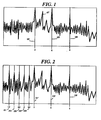
- FIG. 1 is a chart illustrating an engine firing spectra attributable to a normal firing condition with all cylinders firing as designed;
- FIG. 2 is a chart illustrating an engine firing spectra attributable to a misfiring condition with one cylinder not firing as designed;
- FIG. 3 is a system block diagram of a misfire detection system, as described in a preferred embodiment;
- FIG. 4 is a system block diagram of a misfire detection system, as described in an alternative embodiment including an engine speed responsive spectral analysis means;
- FIG. 5 is a system block diagram of a misfire detection system, as described in an alternative embodiment, including an engine mounted accelerometer;
- FIG. 6 is a system block diagram of a misfire detection system, as described in an alternative embodiment, including an in-cylinder sensor;
- FIG. 7 is a system block diagram of digital filters used in the preferred, and alternative embodiments for extracting, torsional crankshaft vibrations, firing related spectra, and misfiring related spectra all in the cycles/revolution domain; and
- FIG. 8 is a system block diagram of digital filters used in alternative embodiments for extracting, torsional crankshaft vibrations, firing related spectra, and misfiring related spectra, all in the frequency domain.
- In a preferred embodiment, a system for detecting the presence of a misfire condition by monitoring spectral activity of a running engine is described.
- In the preferred embodiment a spectra related to a characteristic, preferably an acceleration characteristic, indicative of performance of a combustion process, of a running engine is considered. Many diverse means for measuring this characteristic will yield suitable information for determining a misfire condition. For instance, means for measuring engine vibration with an accelerometer, optical means, ionization means, pressure means for measuring an in-cylinder combustion phenomena, or means for measuring motion all associated with an acceleration characteristic indicative of a combustion process are useful. Those skilled in the art will recognize other similar means and methods that can be substituted for these means without departing from the intent of this disclosure.
- The charts of FIG. 1 and FIG. 2 illustrate the acceleration spectral behavior in a cycles/revolution domain indicative of the combustion performance of a running engine. Note that representation in the cycles/revolution domain is convenient because acceleration fluctuations due to combustion, engine imbalance, and engine accessories (such as an alternator, an air conditioner compressor, a fan etc.) remain at the same cycles/revolution occurrence frequency regardless of engine speed.
- In FIG. 1 an engine firing spectra attributable to a normal firing condition of a four stroke six cylinder engine is shown. Note that the power of the acceleration fluctuations is particularly prominent at a series starting at 3 101, 6 103, and 9 105 cycles/revolution. Although higher order harmonics, or partials, are in the series they are insignificant compared to systemic noise. Also note a strong response shown by
reference number 107. This represents a spectral response directly resulting from a crankshaft torsional effect. Note that the normal firing spectral phenomena is independent of engine speed in the cycles/revolution domain, and the torsional vibration spectra is variable in the cycles/revolution domain given that the torsional vibration has a constant frequency behavior. - FIG. 2 shows an engine firing spectra attributable to a misfiring condition with one cylinder not firing. Note that power is still particularly prominent at a series starting at 3 101', 6 103', and 9 105' cycles/revolution but also at 1/2 201, 1 203, 3/2 205, 2 207, and 5/2 209 cycles/revolution. This sub-harmonic series behavior is indicative of only one cylinder misfiring. If a pair of cylinders misfires, predominant energy would appear at a series starting with 1 and 2 cycles/revolution. This behavior is fairly common, and is attributable to a failure of a shared ignition coil, typically found in contemporary ignition systems.
- Of course, in engine arrangements with a different number of cylinders, a misfiring ignition pair would have a different but similarly predictable spectral behavior. Additionally, in non-even firing engines the spectral behavior of the acceleration characteristic would have a correspondingly predictable spectral behavior.
- The fundamental, or lowest order firing frequency for all engines, either two stroke or four stroke is representable by the following relationship:


- Tp
- = instantaneous pressure torque
- Tm
- = mean torque of the engine
- Wn, fn
- = coefficients that vary with engine type and operating conditions
- n
- = harmonic order
- q
- = engine rotational position
- A chart illustrating characteristic frequencies for a four stroke, even firing engine for different cylinder arrangements, is provided as follows:

- Thus, spectra resulting from a misfiring condition will be located a fixed spectral distance below the spectra associated with a normal firing condition.
- A system for recognizing the aforementioned behavior includes a spectral sensing means, coupled to a running engine, for providing a spectral signal representative of the spectral activity of the running engine, indicative of the engine's performance. In the preferred embodiment a crankshaft position sensor is used to measure angular displacement, and is then conditioned to provide a composite signal representative of crankshaft acceleration. Other embodiments, detailed later, will include other sensing mechanisms for measuring motion associated with an acceleration characteristic, indicative of performance of the combustion process of the running engine.
- A spectral discrimination means receives the composite signal provided by the measurement means, and provides a normal firing signal that corresponds to spectral energy attributable to a portion of the composite signal representative of a normal firing condition. If a misfiring condition exists, the spectral discrimination means further provides a misfire signal, corresponding to spectral energy attributable to another portion of the composite signal representative of the misfiring condition of the running engine. Then a misfire indication is provided if a magnitude of the misfire signal exceeds a magnitude of the firing signal by a predetermined factor.
- FIG. 3 shows a system block diagram of a misfire detection system that applies this behavior recognition strategy to render improved detection of a misfire condition in a running engine. In the preferred embodiment a six cylinder, 4 stroke engine is used. In the preferred embodiment, a central element for detecting a misfire condition is implemented using discrete time signal processing elements.
- Alternatively, those skilled in the art will recognize other equivalent embodiments such as those using conventional continuous time signal processing elements, including conventional analog circuits. Discrete time signal processing was chosen because of the benefits it has over continuous time signal processing elements. These benefits include fewer components, stable deterministic performance, no aging, no drift, no adjustments, easily tunable for various engines, high noise immunity, and self test capability.
- As mentioned earlier, a crankshaft displacement sensor is used to measure angular displacement, which is then conditioned to provide a composite signal representative of crankshaft acceleration due to the performance of the combustion process in the running engine. To accomplish this measurement, in FIG. 3 a
sensor 301 measures a passingtooth 303 on arotating wheel 305, that is attached to a running engine's crankshaft. This practice of using a toothed wheel on a crankshaft is commonplace in the field of engine control. Of course, those skilled in the art will recognize many other, substantially equivalent, means and methods to measure angular displacement. An engineangular displacement signal 307 is provided by thesensor 301. In the preferred embodiment, as the engine runs, theangular displacement signal 307 is typically a logic level signal that transitions when thesensor 301 senses thetooth 303 and asubsequent space 311. Therefore, as thetoothed wheel 305 rotates, responsive to the combustion process in the running engine, theangular displacement signal 307 is substantially a rectangular waveform responsive to angular velocity, or engine speed. - This
angular displacement signal 307 is provided toelement 309.Element 309 determines an acceleration of the running engine's crankshaft. Those skilled in the art will recognize several means and methods for doing this. In the preferred embodiment, elapsed time intervals between adjacent transitions of therectangular wave 307 are compared to determine crankshaft acceleration. It is preferable to filter this determined acceleration to remove any torsional vibrations or other acceleration effects not related to misfire behavior. This is described later. - The acceleration information is then provided to
element 313. In the preferred embodiment,element 313 samples the acceleration information synchronous with engine angular displacement. As mentioned earlier the spectral phenomena of the acceleration information of interest, that is for detecting engine firing and misfiring spectra, is independent of engine speed, if engine synchronous sampling is used. Thus, in this embodiment,element 313 is simply a gate controlled by theangular displacement signal 307.Element 313 outputs, a composite signal, or acquisitioned enginecrankshaft acceleration signal 317, representative of engine spectral emissions related to the combustion performance of the running engine. - As mentioned earlier, the preferred embodiment relies on discrete time signal processing elements.
Element 315 represents a Digital Signal Processor, or DSP. The constituent system level block diagram elements illustrated withinelement 315 represent hardware means microcoded with appropriate software routines. In this case aMotorola DSP56001 315 device is used. The Motorola DSP56001 has the capability of executing over ten million instructions per second, and with 24 bit wide data paths provides 144 dB of dynamic range. Of course, those skilled in the art will recognize other equivalently useful DSP devices, or hardwired, or other microcoded approaches that have substantially the same function. - The key element of this implementation includes a digital filter, represented by
element 319. This filter is comprised of three separate filters as detailed in FIG. 7. - Referring to FIG. 7 this
filter 319 includes a noise filtering means, or anotch filter 701 located to eliminate any effect from the crankshaft torsional spectral element. This noise filtering means 701, or noise spectral discrimination means, receives a composite spectral signal, in this case the acquisitioned enginecrankshaft acceleration signal 317, and provides a noise filteredsignal 703 absent of a predetermined noise component of the composite spectral signal. In this case the predetermined noise component is the crankshaft torsional vibration. Because the cycles/revolution domain is used in this embodiment, and the torsional vibration spectral element is constant in the frequency domain, thisfilter 701 must be tuned synchronous with engine speed. To this end,element 333 determines engine speed and provides anoutput variable 335 corresponding to the speed of the enginecrankshaft measurement apparatus - The tuning of
filter 701 is accomplished by deriving variable filter coefficients that correspond to the engine speed. This is particularly convenient in the Motorola DSP56001 and is accomplished by the use of a lookup table with alternative filter coefficients. Alternatively, recalculation of the filter coefficients may be used to, in effect, tune thefilter 701 responsive to thesignal 335 indicative of engine speed. Also, those skilled in the art will recognize the method of re-sampling the data into the frequency domain, applying a fixed filter, and re-sampling into the cycles/revolution domain as another alternative. Thefilter 701 provides the noise filteredsignal 703 to both afiring filter bank 707, and misfiringfilter bank 705. - As noted above for the
notch filter 701,filters filters - The firing
filter bank 707 is designed to extract spectral energy expected from the noise filteredsignal 703 related to normal firing at 3, 6, and 9 cycles/revolution. Alternatively, if lesser accuracy is needed, the firingfilter bank 707 can directly extract spectral energy expected from the compositespectral signal 317. The firingfilter bank 707 provides anormal firing signal 321, corresponding to spectral energy, or power attributable to a portion of the noise filteredsignal 703 representative of energy caused by a normal firing condition in the running engine. - The
misfiring filter bank 705 is designed to extract spectral energy expected from the noise filteredsignal 703 related to misfiring at 1/2, 1, 3/2, 2, and 5/2 cycles/revolution. It provides amisfire signal 323, corresponding to spectral energy attributable to another portion of the composite signal representative of a misfiring condition in the running engine. - Note that in the preferred embodiment a six cylinder, 4 stroke engine is used. If another engine configuration is used the proper spectral relationships are shown in Table 1.
- Of course, those skilled in the art will recognize other uses for the
notch filter 701, including the elimination of other unwanted systemic noise, such as that due to force imbalances, road related disturbances, and engine accessory related noise. To filter out some of these other phenomena, multiple notches, or differently tuned rejection bands, may be used. - The
digital filters DSP56001 315 is programmed to implement these digital filters. FIR filters are very commonly designed using thisDSP 315. - In the preferred embodiment, and some of the others described later, the fact that the spectral phenomena of interest is independent of engine speed in the cycles/revolution domain makes it convenient to apply engine synchronous sampling. To do this, the digital filter coefficients, for normal firing at 3, 6, and 9 cycles/revolution, and for misfiring at 1/2, 1, 3/2, 2, and 5/2 cycles/revolution are specified in terms of the sampling, or data, rate in accordance with the Nyquist Theorem in the cycles/revolution domain. Therefore, because the digital filters' coefficients have a fixed relationship to the sampling rate, as the engine changes speed, since the phenomena of interest remains constant in the cycles/revolution domain the
filters - After filtering, the
normal firing signal 321 and themisfire signal 323 are provided from thedigital filters element 325.Element 325 provides amisfire indication signal 327 when a magnitude of themisfire signal 323 exceeds a magnitude of thefiring signal 321 by a predetermined factor. This predetermined factor is preferably adjustable for different engine families. - The
misfire indication signal 327 is preferably provided toelement 329 which shuts off the fuel delivery to the misfiring cylinder. Themisfire indication signal 327 may also be provided outside this system for reporting a misfire condition to another engine controller, or diagnostic apparatus. - To identify the particular cylinder coincident with the
misfire indication signal 327,element 331 is provided.Element 331 considers theangular displacement signal 307 and aTDC marker signal 333 to compute the cylinder currently in the combustion process. Anothersensor 335 andtooth 337 are attached to a camshaft of the engine and used to provide the TDC, or cylinder identification,marker signal 333. Many apparatus and methods of identifying and disabling a misfiring cylinder, once the difficult task of accurately identifying misfire is complete, is well known to those skilled in the art of engine design. - Note that with the approach described in the preferred embodiment the acceleration characteristic measured, associated with firing and misfiring combustion performance, is independent of measurement path length between the running engine, exemplified by the
toothed wheel 305 and the sensory system, represented by thesensor 301. This is also true in a multiple cylinder design. This is a substantial advantage over some prior art systems. Additionally, having free space as a coupling media asserts no load on the engine and has no substantial effect on the characteristic measured, as in prior art systems that relied on a necessarily burdensome coupling medium. - The elegance of this embodiment includes a fixed, stable spectral discrimination means that relies on an input data rate, or sample rate directly derived by engine speed. This engine synchronous sampling approach is not possible with a tuned analog filter implementation used in prior art, but is convenient with a digital filter. Also, since a single point in the engine is used to measure the combustion performance, the measurement is independent of measurement path length and geometry, thus no measurement path coupling or multipath errors are introduced as in the prior art.
- Other embodiments are shown in FIG.'s 4, 5, and 6. In FIG. 4 the same crankshaft sensory system is employed with digital filters associated with the frequency domain, rather than the cycles/revolution domain.
- Element 313' inputs the crankshaft acceleration information provided by
element 309 at a fixed sampling rate. Of course, this fixed sampling speed is chosen to be high enough to conform to the Nyquist Theorem requirements to ensure that aliasing does not occur. Element 313' is constructed using a gate controlled by a clocking oscillator, and provides an output 317' at a constant sample rate to element 319'. - Referring to FIG. 8 this filter 319' has substantially the same structure as found in the
filter 319, detailed in FIG. 7. However, because this approach uses a fixed sampling rate, in time, the data, represented by 317', is in the frequency domain. Thus, thedigital filter 701' can be stationary and thedigital filters 705' and 707' must be tunable to track engine speed. This is because since the sampling rate is fixed, and the torsional vibration spectral phenomena is fixed in the frequency domain,digital filter 701' can be fixed. Also, the firing and misfiring spectral phenomena of interest does not remain constant in the frequency domain as it did in the preferred embodiment in the cycles/revolution domain, and therefore thesefilters 705', 707' must be tuned to track engine speed. In this embodiment theengine speed variable 335 is provided to tunefilters 705' and 707'. - As described in the preferred embodiment, preferably, the
filter 701' is designed as a notch filter, but here the filter coefficients are fixed and are specified in the frequency domain. Specifically,filter 701 is tuned fixed to 240 Hz which corresponds to 4.5 cycles/revolution at 3,210 RPM. Note that this filter remains stationary because the effective crankshaft torsional vibration effect is fixed in the frequency domain. - The output 703', or noise filtered signal, of this
filter 701' provides the torsional vibration free signal to theother filters 705', and 707'. - Filter 707' is configured as a digital multiple bandpass filter having a response that discriminates a spectrum corresponding to frequencies representing 3, 6, and 9 cycles/revolution at a known engine speed. The digital filter's 707' coefficients are variable and are specified in the frequency domain. Specifically, filter 707' is tuned to 160 Hz, 320 Hz, and 480 Hz for an engine speed of 3,210 RPM. If the engine speed is reduced by 50% to 1,605 RPM then new filter coefficients are looked up as mentioned earlier, and the filter 707' is correspondingly tuned to 80 Hz, 160 Hz, and 240 Hz.
-
Filter 705' is also configured as a digital multiple bandpass filter having a response that discriminates a spectrum corresponding to frequencies representing misfiring at 1/2, 1, 3/2, 2, and 5/2 cycles/revolution. The digital filter's 705 coefficients are variable and are specified in the frequency domain. Specifically,filter 705 is tuned to 27 Hz, 53 Hz, 80 Hz, 106 Hz, and 160 Hz for an engine speed of 3,210 RPM. If the engine speed is reduced by 50% to 1,605 RPM then new filter coefficients are looked up, as mentioned earlier, and thefilter 705 is correspondingly tuned to 13 Hz, 27 Hz, 40 Hz, 53 Hz, and 80 Hz. - Each of these filters, 707', and 705' output a signal 321' and 323' for indicating spectral energy located at a predicted firing frequencies and misfiring frequencies correspondingly. The other elements perform as described earlier in the discussion about FIG. 3.
- In FIG. 5 an engine mounted
accelerometer 501, conveniently the same one that may be used for knock detection, is employed to measure the combustion performance. Aside from the substitution of the sensory means this embodiment works the same as the preferred embodiment. - Although FIG. 5 is shown using the engine synchronous sampling approach common to measurement in the cycles/revolution domain the fixed sample rate, or frequency domain, approach may alternatively be applied. In addition to the earlier stated advantages, this approach shares a sensor with a to be provided knock detection function. This is significant to cost savings, factory installation and field repair ease and field reliability. Additionally, this approach is insensitive to crankshaft torsional vibrations.
- In FIG. 6 an in-
cylinder sensor 601 is employed to measure the combustion performance. Various types of sensors can be employed. A subset of these include optical, pressure, and ionization sensors. Also, a sensor on each of the cylinders can be used. If sensors are provided on multiple cylinders then their outputs are preferably combined into the misfire detection system. Alternatively, the sensors may be individually analyzed. FIG. 6 shows the frequency domain approach. - Element 313' inputs combustion information provided by the in-cylinder sensor, 601 at a fixed sampling rate. This element 313' is identical to the element described in FIG. 4. The sampled data 317' is provide to the filter 319' The filter 319' is designed to operate the same as the filter described in FIG. 4. The other elements perform as described earlier in the discussion about FIG. 3.
- Alternatively, if the cylinders are individually analyzed, the digital filter is tuned to detect one-half cycles/revolution for a proper firing, and an absence of a firing, or significantly attenuated firing energy at one-half cycles/revolution indicates a misfire.
- Of course, the engine synchronous sampling approach may alternatively be employed. In addition to the earlier stated advantages, this approach directly measures the combustion process and is not affected by the extraneous systemic noise sources, such as crankshaft torsional effects, that affect the other sensing techniques.
- In conclusion, a system for detecting the presence of a misfire condition by monitoring spectral activity through measuring motion associated with an acceleration characteristic indicative of performance of a combustion process of a running engine, has been presented. The preferred and alternative embodiments overcome the significant disadvantages of the prior art. Improvements include a more accurate detection of a misfiring condition because the measurement path is direct, there is an improved insensitivity to external influences, a singular measurement path not effected by multi-path induced errors, and this approach avoids any inaccuracy due to multi-cycle averaging. This system is also more stable and the results more predictable, because of the digital filter implementation. Further, this approach is more responsive to transient engine operating conditions because no multi-cycle averaging is employed. This approach is also independent of energy emitted and does not pose a loading problem on the measured engine as prior art systems did. Because all engines exhibit the misfire behavior at the known spectra, this system requires minimum calibration, and can be easily applied to different engine families.
- Although the embodiment proposed herein rely on a particular systemic approach, many other systems, and methods (with other apparatus) could be devised to yield the same advantages of this approach.
Claims (21)
- An apparatus for improving signal fidelity in a misfire detection system of a running engine, the apparatus comprising:
acceleration measurement means for providing an acceleration signal indicative of acceleration behavior of the running engine;
means for determining the running engine's speed; and
filtering means programmable dependent on the running engine's speed, the filtering means for providing a filtered acceleration signal responsive to the acceleration signal provided by the acceleration measurement means. - An apparatus in accordance with claim 1 further comprising:
acceleration discrimination means for receiving the filtered acceleration signal provided by said filtering means, and for providing a normal firing signal, corresponding to acceleration behavior attributable to a portion of the composite signal representative of a normal firing condition and, concurrent to the provision of the normal firing signal, for providing a misfire signal, corresponding to acceleration behavior attributable to another portion of the composite signal representative of a misfiring condition; and
comparison means for receiving the normal firing signal and the misfire signal, both signals provided by said acceleration discrimination means, and for providing a misfire indication when a magnitude of the misfire signal exceeds a magnitude of the normal firing signal. - An apparatus in accordance with claim 2 wherein said acceleration measurement means comprises means for measuring engine angular acceleration corresponding to an angular displacement of said running engine.
- An apparatus in accordance with claim 2 wherein said acceleration measurement means comprises means for measuring acceleration corresponding to vibration of said running engine.
- An apparatus in accordance with claim 2 wherein said acceleration measurement means comprises means for measuring an in-cylinder combustion phenomena dependent on an acceleration behavior of said running engine.
- An apparatus in accordance with claim 2 further comprising means for shutting off fuel to a cylinder, responsive to the provision of said misfire indication.
- An apparatus in accordance with claim 2 wherein said acceleration discrimination means comprises a normal firing acceleration discrimination means responsive to spectral energy attributable to a portion of the composite signal representative of a normal firing condition, and a misfiring signal acceleration discrimination means responsive to spectral energy attributable to a portion of the composite signal representative of a misfiring condition, wherein said misfiring signal acceleration discrimination means is spectrally discriminatory a predetermined fixed spectral distance below said normal firing spectral discrimination means.
- An apparatus in accordance with claim 7 wherein said misfiring signal spectral discrimination means comprises multiple spectral discrimination means predominantly responsive to frequencies located at one-half, one, and three-halves cycles/revolution of a predominant spectral location of the normal firing spectral discrimination means.
- An apparatus in accordance with claim 8 further comprising:
means for providing a synchronization signal representative of said running engine's speed; and
wherein said acceleration measurement means of said running engine measures said acceleration at a sample rate responsive to the synchronization signal provided by said means for providing a synchronization signal. - An apparatus in accordance with claim 7 wherein a predominant spectral location of said acceleration discrimination means are tunable.
- An apparatus in accordance with claim 10 further comprising:
means for providing a synchronization signal representative of said running engine's speed; and
wherein the predominant spectral location of said acceleration discrimination means is tuned responsive to the synchronization signal provided by said means for providing a synchronization signal. - An apparatus in accordance with claim 2 wherein said acceleration measurement means measures the acceleration independent of a measurement path length between a motion associated with the acceleration indicative of performance of a combustion process of said running engine and said means for measuring the acceleration.
- An apparatus in accordance with claim 2 wherein said acceleration measurement means measures the acceleration independent of a measurement path length between said running engine and said means for measuring in a multiple cylinder engine.
- An apparatus in accordance with claim 13 wherein a coupling media used by said acceleration measurement means asserts no load on the engine and has no substantial effect on the acceleration measured.
- An apparatus for detecting a misfire condition by interpreting acceleration activity of a running engine comprising:
acceleration sensing means, coupled to said running engine, for providing a signal representative of said acceleration activity of said running engine and for providing a composite signal in response thereto;
acceleration discrimination means for receiving the composite signal provided by said acceleration sensing means, and for providing a normal firing signal, corresponding to acceleration behavior attributable to a portion of the composite signal representative of a normal firing condition, and, concurrent to the provision of the normal firing signal, for providing a misfire signal, corresponding to acceleration behavior attributable to another portion of the composite signal representative of a misfiring condition; and
means for providing an indication of a misfire condition when a magnitude of the misfire signal exceeds a magnitude of the firing signal by a predetermined factor. - An apparatus in accordance with claim 15 wherein said acceleration sensing means comprises an accelerometer coupled to said running engine.
- An apparatus in accordance with claim 15 wherein said acceleration sensing means comprises means for sensing an acceleration of a crankshaft coupled to said running engine.
- An apparatus in accordance with claim 15 wherein said acceleration sensing means further comprises:
speed sensing means for providing a synchronization signal representative of said running engine's speed; and
wherein said acceleration discrimination means comprises a frequency tunable normal firing acceleration filtering means responsive to acceleration behavior attributable to a portion of the composite signal representative of a normal firing condition, and a frequency tunable misfiring signal acceleration filtering means responsive to acceleration behavior attributable to a portion of the composite signal representative of a misfiring condition, wherein said frequency tunable misfiring signal acceleration filtering means is spectrally located a predetermined fixed spectral distance below said frequency tunable normal firing acceleration filtering means and wherein both said frequency tunable normal firing acceleration filtering means, and said frequency tunable misfiring acceleration filtering means are spectrally tuned responsive to said synchronization signal provided by said speed sensing means. - An apparatus in accordance with claim 18 wherein said frequency tunable misfiring signal acceleration filtering means comprises multiple acceleration filtering means predominantly responsive to acceleration spectra located at one-half, one, and three-halves cycles/revolution of a predominant spectral location of the normal firing spectral discrimination means.
- A method for detecting a misfire condition by interpreting acceleration of a running engine comprising the steps of:
providing an acceleration signal indicative of acceleration behavior of the running engine;
determining a speed of the running engine;
providing a filtered acceleration signal responsive to the step of providing an acceleration signal dependent on the speed of the running engine determined on the step of determining;
spectrally discriminating the composite signal provided in said step of measuring, and for providing a normal firing signal corresponding to spectral energy attributable to a portion of the composite signal representative of a normal firing condition in said running engine, and, concurrent to the provision of the normal firing signal, for providing a misfire signal, corresponding to spectral energy attributable to another portion of the composite signal representative of a misfiring condition in said running engine; and
comparing the normal firing signal and the misfire signal, both signals provided in said step of measuring, and for providing a misfire indication when a magnitude of the misfire signal exceeds a magnitude of the normal firing signal. - An apparatus for detecting a misfire condition by interpreting spectral activity of a running engine comprising:
means for measuring a characteristic, indicative of performance of a combustion process of said running engine, and for providing a composite spectral signal representative of the performance of said combustion process;
noise spectral discrimination means for receiving the composite spectral signal provided by said means for measuring a characteristic, and for providing a noise filtered signal absent of a predetermined noise component of the composite spectral signal;
spectral discrimination means for receiving the noise filtered signal provided by said noise spectral discrimination means, and for providing a normal firing signal, corresponding to spectral energy attributable to a portion of the composite signal representative of a normal firing condition in said running engine, and for providing a misfire signal, corresponding to spectral energy attributable to another portion of the composite signal representative of a misfiring condition in said running engine; and
means for providing an indication of a misfire condition when a magnitude of the misfire signal exceeds a magnitude of the firing signal by a predetermined factor.
Priority Applications (3)
| Application Number | Priority Date | Filing Date | Title |
|---|---|---|---|
| ES94117153T ES2161234T3 (en) | 1994-10-31 | 1994-10-31 | DETECTION OF IGNITION FAILURE THROUGH ACCELERATION DISCRIMINATION. |
| EP94117153A EP0709664B1 (en) | 1994-10-31 | 1994-10-31 | Detecting misfire with acceleration discrimination |
| DE1994627984 DE69427984T2 (en) | 1994-10-31 | 1994-10-31 | Misfire detection through acceleration differentiation |
Applications Claiming Priority (1)
| Application Number | Priority Date | Filing Date | Title |
|---|---|---|---|
| EP94117153A EP0709664B1 (en) | 1994-10-31 | 1994-10-31 | Detecting misfire with acceleration discrimination |
Publications (2)
| Publication Number | Publication Date |
|---|---|
| EP0709664A1 true EP0709664A1 (en) | 1996-05-01 |
| EP0709664B1 EP0709664B1 (en) | 2001-08-16 |
Family
ID=8216425
Family Applications (1)
| Application Number | Title | Priority Date | Filing Date |
|---|---|---|---|
| EP94117153A Expired - Lifetime EP0709664B1 (en) | 1994-10-31 | 1994-10-31 | Detecting misfire with acceleration discrimination |
Country Status (3)
| Country | Link |
|---|---|
| EP (1) | EP0709664B1 (en) |
| DE (1) | DE69427984T2 (en) |
| ES (1) | ES2161234T3 (en) |
Cited By (8)
| Publication number | Priority date | Publication date | Assignee | Title |
|---|---|---|---|---|
| GB2304899A (en) * | 1995-08-29 | 1997-03-26 | Bosch Gmbh Robert | Combustion misfire sensing method |
| WO1997011345A1 (en) * | 1995-09-21 | 1997-03-27 | Robert Bosch Gmbh | Process for detecting misfiring by assessing rotation speed variations |
| US6179458B1 (en) | 1996-11-01 | 2001-01-30 | E. I. Du Pont De Nemours And Company | Forming a solution of fluids having low miscibility and large-scale differences in viscosity |
| GB2354586A (en) * | 1999-06-28 | 2001-03-28 | Ford Global Tech Inc | Misfire detection system of an internal combustion engine |
| US6658346B2 (en) * | 2000-08-03 | 2003-12-02 | Denso Corporation | Misfire detection apparatus for internal combustion engine |
| US8078389B2 (en) | 2007-11-27 | 2011-12-13 | Westport Power Inc. | Method and apparatus for determining a normal combustion characteristic for an internal combustion engine from an accelerometer signal |
| US20140277997A1 (en) * | 2013-03-15 | 2014-09-18 | Mark Shaffer | Electronic Detection of Engine Malfunction |
| US9243573B2 (en) | 2013-05-31 | 2016-01-26 | Ford Global Technologies, Llc | Methods and systems for cylinder bank misfire detection and reactivation |
Families Citing this family (1)
| Publication number | Priority date | Publication date | Assignee | Title |
|---|---|---|---|---|
| JP3997878B2 (en) * | 2002-10-02 | 2007-10-24 | 株式会社日立製作所 | Misfire detection device |
Citations (9)
| Publication number | Priority date | Publication date | Assignee | Title |
|---|---|---|---|---|
| DE2658614A1 (en) * | 1975-12-25 | 1977-07-07 | Nissan Motor | METHOD AND DEVICE FOR SENSING MISSING IGNITIONS IN INTERNAL COMBUSTION MACHINES |
| DE2912773A1 (en) * | 1979-03-30 | 1980-10-09 | Bosch Gmbh Robert | Measuring IC engine running unevenness - using accelerometer or speed transducer with output filter, rectifier and integrator |
| US4424709A (en) * | 1982-07-06 | 1984-01-10 | Ford Motor Company | Frequency domain engine defect signal analysis |
| EP0306905A2 (en) * | 1987-09-09 | 1989-03-15 | Jenbacher Werke AG | Misfire detecting device |
| DE3933008A1 (en) * | 1988-10-04 | 1990-04-05 | Mitsubishi Electric Corp | CONTROL DEVICE FOR AN INTERNAL COMBUSTION ENGINE |
| EP0441603A2 (en) * | 1990-02-09 | 1991-08-14 | Lucas Industries Public Limited Company | Misfire detection |
| WO1991013333A1 (en) * | 1990-02-28 | 1991-09-05 | Forschungsinstitut Für Kraftfahrwesen Und Fahrzeugmotoren Stuttgart | Process and device for measuring the variation in internal pressure in the cylinder of a piston engine |
| US5200899A (en) * | 1990-04-20 | 1993-04-06 | Regents Of The University Of Michigan | Method and system for detecting the misfire of an internal combustion engine utilizing angular velocity fluctuations |
| US5303158A (en) * | 1990-05-14 | 1994-04-12 | Honda Giken Kogyo Kabushiki Kaisha | Misfire-detecting system for an internal combustion engine |
Family Cites Families (1)
| Publication number | Priority date | Publication date | Assignee | Title |
|---|---|---|---|---|
| US5278760A (en) * | 1990-04-20 | 1994-01-11 | Hitachi America, Ltd. | Method and system for detecting the misfire of an internal combustion engine utilizing engine torque nonuniformity |
-
1994
- 1994-10-31 EP EP94117153A patent/EP0709664B1/en not_active Expired - Lifetime
- 1994-10-31 ES ES94117153T patent/ES2161234T3/en not_active Expired - Lifetime
- 1994-10-31 DE DE1994627984 patent/DE69427984T2/en not_active Expired - Fee Related
Patent Citations (9)
| Publication number | Priority date | Publication date | Assignee | Title |
|---|---|---|---|---|
| DE2658614A1 (en) * | 1975-12-25 | 1977-07-07 | Nissan Motor | METHOD AND DEVICE FOR SENSING MISSING IGNITIONS IN INTERNAL COMBUSTION MACHINES |
| DE2912773A1 (en) * | 1979-03-30 | 1980-10-09 | Bosch Gmbh Robert | Measuring IC engine running unevenness - using accelerometer or speed transducer with output filter, rectifier and integrator |
| US4424709A (en) * | 1982-07-06 | 1984-01-10 | Ford Motor Company | Frequency domain engine defect signal analysis |
| EP0306905A2 (en) * | 1987-09-09 | 1989-03-15 | Jenbacher Werke AG | Misfire detecting device |
| DE3933008A1 (en) * | 1988-10-04 | 1990-04-05 | Mitsubishi Electric Corp | CONTROL DEVICE FOR AN INTERNAL COMBUSTION ENGINE |
| EP0441603A2 (en) * | 1990-02-09 | 1991-08-14 | Lucas Industries Public Limited Company | Misfire detection |
| WO1991013333A1 (en) * | 1990-02-28 | 1991-09-05 | Forschungsinstitut Für Kraftfahrwesen Und Fahrzeugmotoren Stuttgart | Process and device for measuring the variation in internal pressure in the cylinder of a piston engine |
| US5200899A (en) * | 1990-04-20 | 1993-04-06 | Regents Of The University Of Michigan | Method and system for detecting the misfire of an internal combustion engine utilizing angular velocity fluctuations |
| US5303158A (en) * | 1990-05-14 | 1994-04-12 | Honda Giken Kogyo Kabushiki Kaisha | Misfire-detecting system for an internal combustion engine |
Cited By (13)
| Publication number | Priority date | Publication date | Assignee | Title |
|---|---|---|---|---|
| GB2304899A (en) * | 1995-08-29 | 1997-03-26 | Bosch Gmbh Robert | Combustion misfire sensing method |
| GB2304899B (en) * | 1995-08-29 | 1997-11-05 | Bosch Gmbh Robert | Combustion misfire sensing method |
| US5691469A (en) * | 1995-08-29 | 1997-11-25 | Robert Bosch Gmbh | Method of detecting combustion misfires |
| WO1997011345A1 (en) * | 1995-09-21 | 1997-03-27 | Robert Bosch Gmbh | Process for detecting misfiring by assessing rotation speed variations |
| US5875411A (en) * | 1995-09-21 | 1999-02-23 | Robert Bosch Gmbh | Method of detecting combustion misfires by evaluating RPM fluctuations |
| US6179458B1 (en) | 1996-11-01 | 2001-01-30 | E. I. Du Pont De Nemours And Company | Forming a solution of fluids having low miscibility and large-scale differences in viscosity |
| GB2354586A (en) * | 1999-06-28 | 2001-03-28 | Ford Global Tech Inc | Misfire detection system of an internal combustion engine |
| GB2354586B (en) * | 1999-06-28 | 2003-07-23 | Ford Global Tech Inc | Misfire detection system of an internal combustion engine |
| US6658346B2 (en) * | 2000-08-03 | 2003-12-02 | Denso Corporation | Misfire detection apparatus for internal combustion engine |
| US8078389B2 (en) | 2007-11-27 | 2011-12-13 | Westport Power Inc. | Method and apparatus for determining a normal combustion characteristic for an internal combustion engine from an accelerometer signal |
| US20140277997A1 (en) * | 2013-03-15 | 2014-09-18 | Mark Shaffer | Electronic Detection of Engine Malfunction |
| US9243573B2 (en) | 2013-05-31 | 2016-01-26 | Ford Global Technologies, Llc | Methods and systems for cylinder bank misfire detection and reactivation |
| US9599048B2 (en) | 2013-05-31 | 2017-03-21 | Ford Global Technologies, Llc | Methods and systems for cylinder bank misfire detection and reactivation |
Also Published As
| Publication number | Publication date |
|---|---|
| DE69427984D1 (en) | 2001-09-20 |
| DE69427984T2 (en) | 2002-06-13 |
| ES2161234T3 (en) | 2001-12-01 |
| EP0709664B1 (en) | 2001-08-16 |
Similar Documents
| Publication | Publication Date | Title |
|---|---|---|
| US5387253A (en) | Spectral misfire detection system and method therefor | |
| US5200899A (en) | Method and system for detecting the misfire of an internal combustion engine utilizing angular velocity fluctuations | |
| US5278760A (en) | Method and system for detecting the misfire of an internal combustion engine utilizing engine torque nonuniformity | |
| US5239473A (en) | Method and system for detecting the misfire of an internal combustion engine utilizing angular velocity fluctuations | |
| US5633456A (en) | Engine misfire detection with digital filtering | |
| AU750684B2 (en) | Process for detecting a misfire in an internal combustion engine and system for carrying out said process | |
| US5230316A (en) | Method and apparatus for detecting knock in an internal combustion engine | |
| US5862507A (en) | Real-time misfire detection for automobile engines with medium data rate crankshaft sampling | |
| EP0632261B1 (en) | System for detection of low power in at least one cylinder of a multi-cylinder engine | |
| KR0147278B1 (en) | Engine controller equipped with knocking detector | |
| EP0677165B1 (en) | System to determine engine misfire | |
| US6456927B1 (en) | Spectral knock detection method and system therefor | |
| JPH0968542A (en) | Analytical tachometer | |
| Burgdorf et al. | Comparison of cylinder pressure based knock detection methods | |
| US6314802B1 (en) | Optimal engine speed compensation method used in misfire detection | |
| Samimy et al. | Engine knock analysis and detection using time-frequency analysis | |
| JPH0658196A (en) | Miss fire detecting device | |
| EP0709664B1 (en) | Detecting misfire with acceleration discrimination | |
| Willimowski et al. | A time domain based diagnostic system for misfire detection in spark-ignition engines by exhaust-gas pressure analysis | |
| JPS61137037A (en) | Absolute compression measuring method and device | |
| Ribbens et al. | Onboard diagnosis of engine misfires | |
| US5616834A (en) | Misfire detection dependent on intake air charge fluctuations | |
| JPH0347449A (en) | Knocking sensing device and engine control device | |
| EP1559898A1 (en) | Method for determining the variation of engine speed | |
| US5503007A (en) | Misfire detection method and apparatus therefor |
Legal Events
| Date | Code | Title | Description |
|---|---|---|---|
| PUAI | Public reference made under article 153(3) epc to a published international application that has entered the european phase |
Free format text: ORIGINAL CODE: 0009012 |
|
| AK | Designated contracting states |
Kind code of ref document: A1 Designated state(s): DE ES FR GB IT |
|
| 17P | Request for examination filed |
Effective date: 19961104 |
|
| 17Q | First examination report despatched |
Effective date: 19970618 |
|
| RTI1 | Title (correction) |
Free format text: DETECTING MISFIRE WITH ACCELERATION DISCRIMINATION |
|
| GRAG | Despatch of communication of intention to grant |
Free format text: ORIGINAL CODE: EPIDOS AGRA |
|
| GRAG | Despatch of communication of intention to grant |
Free format text: ORIGINAL CODE: EPIDOS AGRA |
|
| GRAH | Despatch of communication of intention to grant a patent |
Free format text: ORIGINAL CODE: EPIDOS IGRA |
|
| GRAH | Despatch of communication of intention to grant a patent |
Free format text: ORIGINAL CODE: EPIDOS IGRA |
|
| ITF | It: translation for a ep patent filed |
Owner name: BARZANO' E ZANARDO ROMA S.P.A. |
|
| GRAA | (expected) grant |
Free format text: ORIGINAL CODE: 0009210 |
|
| AK | Designated contracting states |
Kind code of ref document: B1 Designated state(s): DE ES FR GB IT |
|
| REF | Corresponds to: |
Ref document number: 69427984 Country of ref document: DE Date of ref document: 20010920 |
|
| REG | Reference to a national code |
Ref country code: ES Ref legal event code: FG2A Ref document number: 2161234 Country of ref document: ES Kind code of ref document: T3 |
|
| REG | Reference to a national code |
Ref country code: GB Ref legal event code: IF02 |
|
| ET | Fr: translation filed | ||
| PLBE | No opposition filed within time limit |
Free format text: ORIGINAL CODE: 0009261 |
|
| STAA | Information on the status of an ep patent application or granted ep patent |
Free format text: STATUS: NO OPPOSITION FILED WITHIN TIME LIMIT |
|
| 26N | No opposition filed | ||
| PGFP | Annual fee paid to national office [announced via postgrant information from national office to epo] |
Ref country code: GB Payment date: 20020913 Year of fee payment: 9 |
|
| PGFP | Annual fee paid to national office [announced via postgrant information from national office to epo] |
Ref country code: FR Payment date: 20021003 Year of fee payment: 9 |
|
| PGFP | Annual fee paid to national office [announced via postgrant information from national office to epo] |
Ref country code: ES Payment date: 20021016 Year of fee payment: 9 |
|
| PGFP | Annual fee paid to national office [announced via postgrant information from national office to epo] |
Ref country code: DE Payment date: 20021031 Year of fee payment: 9 |
|
| PG25 | Lapsed in a contracting state [announced via postgrant information from national office to epo] |
Ref country code: GB Free format text: LAPSE BECAUSE OF NON-PAYMENT OF DUE FEES Effective date: 20031031 |
|
| PG25 | Lapsed in a contracting state [announced via postgrant information from national office to epo] |
Ref country code: ES Free format text: LAPSE BECAUSE OF NON-PAYMENT OF DUE FEES Effective date: 20031103 |
|
| PG25 | Lapsed in a contracting state [announced via postgrant information from national office to epo] |
Ref country code: DE Free format text: LAPSE BECAUSE OF NON-PAYMENT OF DUE FEES Effective date: 20040501 |
|
| GBPC | Gb: european patent ceased through non-payment of renewal fee |
Effective date: 20031031 |
|
| PG25 | Lapsed in a contracting state [announced via postgrant information from national office to epo] |
Ref country code: FR Free format text: LAPSE BECAUSE OF NON-PAYMENT OF DUE FEES Effective date: 20040630 |
|
| REG | Reference to a national code |
Ref country code: FR Ref legal event code: ST |
|
| REG | Reference to a national code |
Ref country code: ES Ref legal event code: FD2A Effective date: 20031103 |
|
| PG25 | Lapsed in a contracting state [announced via postgrant information from national office to epo] |
Ref country code: IT Free format text: LAPSE BECAUSE OF NON-PAYMENT OF DUE FEES;WARNING: LAPSES OF ITALIAN PATENTS WITH EFFECTIVE DATE BEFORE 2007 MAY HAVE OCCURRED AT ANY TIME BEFORE 2007. THE CORRECT EFFECTIVE DATE MAY BE DIFFERENT FROM THE ONE RECORDED. Effective date: 20051031 |