EP0710465A1 - Dynamic control of a patient monitoring system - Google Patents
Dynamic control of a patient monitoring system Download PDFInfo
- Publication number
- EP0710465A1 EP0710465A1 EP95111099A EP95111099A EP0710465A1 EP 0710465 A1 EP0710465 A1 EP 0710465A1 EP 95111099 A EP95111099 A EP 95111099A EP 95111099 A EP95111099 A EP 95111099A EP 0710465 A1 EP0710465 A1 EP 0710465A1
- Authority
- EP
- European Patent Office
- Prior art keywords
- data
- telemetry
- dynamic control
- transmitter
- control information
- Prior art date
- Legal status (The legal status is an assumption and is not a legal conclusion. Google has not performed a legal analysis and makes no representation as to the accuracy of the status listed.)
- Withdrawn
Links
Images


Classifications
-
- A—HUMAN NECESSITIES
- A61—MEDICAL OR VETERINARY SCIENCE; HYGIENE
- A61B—DIAGNOSIS; SURGERY; IDENTIFICATION
- A61B5/00—Measuring for diagnostic purposes; Identification of persons
- A61B5/0002—Remote monitoring of patients using telemetry, e.g. transmission of vital signals via a communication network
- A61B5/0015—Remote monitoring of patients using telemetry, e.g. transmission of vital signals via a communication network characterised by features of the telemetry system
- A61B5/002—Monitoring the patient using a local or closed circuit, e.g. in a room or building
-
- G—PHYSICS
- G16—INFORMATION AND COMMUNICATION TECHNOLOGY [ICT] SPECIALLY ADAPTED FOR SPECIFIC APPLICATION FIELDS
- G16H—HEALTHCARE INFORMATICS, i.e. INFORMATION AND COMMUNICATION TECHNOLOGY [ICT] SPECIALLY ADAPTED FOR THE HANDLING OR PROCESSING OF MEDICAL OR HEALTHCARE DATA
- G16H40/00—ICT specially adapted for the management or administration of healthcare resources or facilities; ICT specially adapted for the management or operation of medical equipment or devices
- G16H40/20—ICT specially adapted for the management or administration of healthcare resources or facilities; ICT specially adapted for the management or operation of medical equipment or devices for the management or administration of healthcare resources or facilities, e.g. managing hospital staff or surgery rooms
-
- G—PHYSICS
- G16—INFORMATION AND COMMUNICATION TECHNOLOGY [ICT] SPECIALLY ADAPTED FOR SPECIFIC APPLICATION FIELDS
- G16H—HEALTHCARE INFORMATICS, i.e. INFORMATION AND COMMUNICATION TECHNOLOGY [ICT] SPECIALLY ADAPTED FOR THE HANDLING OR PROCESSING OF MEDICAL OR HEALTHCARE DATA
- G16H40/00—ICT specially adapted for the management or administration of healthcare resources or facilities; ICT specially adapted for the management or operation of medical equipment or devices
- G16H40/60—ICT specially adapted for the management or administration of healthcare resources or facilities; ICT specially adapted for the management or operation of medical equipment or devices for the operation of medical equipment or devices
- G16H40/63—ICT specially adapted for the management or administration of healthcare resources or facilities; ICT specially adapted for the management or operation of medical equipment or devices for the operation of medical equipment or devices for local operation
-
- G—PHYSICS
- G16—INFORMATION AND COMMUNICATION TECHNOLOGY [ICT] SPECIALLY ADAPTED FOR SPECIFIC APPLICATION FIELDS
- G16H—HEALTHCARE INFORMATICS, i.e. INFORMATION AND COMMUNICATION TECHNOLOGY [ICT] SPECIALLY ADAPTED FOR THE HANDLING OR PROCESSING OF MEDICAL OR HEALTHCARE DATA
- G16H40/00—ICT specially adapted for the management or administration of healthcare resources or facilities; ICT specially adapted for the management or operation of medical equipment or devices
- G16H40/60—ICT specially adapted for the management or administration of healthcare resources or facilities; ICT specially adapted for the management or operation of medical equipment or devices for the operation of medical equipment or devices
- G16H40/67—ICT specially adapted for the management or administration of healthcare resources or facilities; ICT specially adapted for the management or operation of medical equipment or devices for the operation of medical equipment or devices for remote operation
-
- Y—GENERAL TAGGING OF NEW TECHNOLOGICAL DEVELOPMENTS; GENERAL TAGGING OF CROSS-SECTIONAL TECHNOLOGIES SPANNING OVER SEVERAL SECTIONS OF THE IPC; TECHNICAL SUBJECTS COVERED BY FORMER USPC CROSS-REFERENCE ART COLLECTIONS [XRACs] AND DIGESTS
- Y10—TECHNICAL SUBJECTS COVERED BY FORMER USPC
- Y10S—TECHNICAL SUBJECTS COVERED BY FORMER USPC CROSS-REFERENCE ART COLLECTIONS [XRACs] AND DIGESTS
- Y10S128/00—Surgery
- Y10S128/903—Radio telemetry
Definitions
- An ambulatory patient may be assigned a telemetry transmitter that is worn by the patient such that telemetry data is transmitted to an array of telemetry antennas and receivers, which are connected to the hospital communications network.
- Reconfiguring the patient monitoring system at transitions between non-ambulatory and ambulatory monitoring modes is a difficult, expensive, and time-consuming task, and typically results in a gap or discontinuity in the stream of monitor data. As a result, a conventional monitoring system is not well-suited for use in a transitional care practice.
- Figure 5 is block schematic diagram of a telemetry docking station featured in Figures 1 and 2.
- the present invention provides increased flexibility in an improved patient monitoring system without requiring significant increase in the size, weight, cost, or battery usage of a telemetry transmitter.
- a telemetry subsystem 100 and a flexible patient monitoring system 200 may be constructed according to the present invention.
- the telemetry subsystem 100 include certain ones of the following components, depending upon the mode of patient monitoring to be performed, and the particular environment(s) in which the subsystem is operating:
- a second preferred embodiment of the MPX 210 contains first and second physiological monitoring sections 216A, 216B which are respectively provided in the form of an ECG monitor and an SpO2 monitor.
- the use of additional or substitute monitoring sections are contemplated as being within the teachings of the present invention, such as a non-invasive blood pressure parameter (NIBP) monitor, a brainwave monitor, and/or other suitable physiological monitors, depending on the need.
- the first physiological monitoring section 216A may be connected to the patient 218 by a sensor 220.
- the sensor 220 would be connected to electrodes attached to the patient's chest.
- a certain ones of the conductors in sensor 220 may also be employed as a data communications link 220A to a primary monitoring instrument 201.
- the MPX 210 features an input/output (I/O) section 240 that operates first, second, and third ports 240A, 240B, 240C.
- the first port 240A may, for example, be a wireless transceiver data port, such as one including an IR transmitter and complying with the serial infrared (SIR) data transmission protocol designed by the Hewlett-Packard Company. Such a first port would interface with one or more SIR receivers present on the portable processor 212 as described above.
- the second port 240B may be directly connected to the telemetry docking station 211 at a respective port 242A and serve as a power and data communications interface between the MPX 210 and the telemetry docking station 211.
- the third port 240C may connect to a backchannel receiver module 213 as will be discussed below.
- an operator can determine at the bedside what primary monitoring data is to be transmitted to the network 205 by use of an instrument telemetry configuration frame displayed on the primary monitoring instrument 201.
- Data will be transferred from the primary monitoring instrument 201 to the MPX 210, which will receive, multiplex, compress, format, and transmit the data as a telemetry signal to a telemetry signal receiving system 203.
- Receivers located in the telemetry signal receiving system 203 receive the telemetry signal and the telemetry receiver interface 233 uses appropriate protocols to convert the telemetry signal into network data messages for transmission over the network 205.
- a backchannel receiver module 213 is detachably mounted on the MPX 210, preferably at port 240C.
- the backchannel receiver module 213 includes a communications and power port 213A, a backchannel receiver 270, and receiving antenna 272.
- Data originating from any node on the network 205 may be directed to the backchannel communications controller 214C for addressable transmission to a particular backchannel receiver module 213. That is, each message sent by backchannel transmitter 214X would include an encoded address so that it is received and/or utilized only by the backchannel receiver module 213 for which it is intended. Once received and translated, the message is provided to the I/O section 240 of the MPX 210.
- the backchannel receiver 270 may operate on an integral battery power source and alternatively may be operated via power provided through the communications and power port 213A; such power may originate from the MPX 210 or from the telemetry docking station 211.
- the requisite circuitry and components that comprise the backchannel receiver 270 and receiving antenna 272 may be constructed in a package that is extremely compact, light in weight, and consumes very little power according to known telecommunications receiver technology.
- the particularly preferred embodiment of the backchannel receiver module 213 is constructed to support a communications backchannel via a paging transmission system.
- the backchannel receiver module 213 is constructed to take advantage of any pre-existing paging transmission system so as to provide inexpensive, two-way communication between the network 205 and the MPX 210.
- most hospitals already employ at least one "local-area" paging system that has been installed and dedicated for hospital use, and many hospital staff members carry a pager. Because the hospital staff members are already carrying portable processors 212 and portable computers 114 for other purposes, and will increasingly do so in the future, the benefits of the present invention are achieved without the significant expense of additional equipment and without any significant change in the way such hospitals and personnel are already operating.
- dynamic control may be effected of the system configuration and of the patient monitoring features and functions performed by the flexible monitoring system 200. Some of such functions may heretofore have required user intervention and/or reconfiguration of one or more of components of a conventional patient monitoring system.
- dynamic control is meant to describe network-based, system-originated control of one or more of the features, functions, or tasks performed by the flexible monitoring system 200.
- the serial infrared port 315 communicates using a subset of the SIR protocol. This port can be "aimed" at the portable processor 212 for establishing an unguided optical communications link, or can be attached to the fiber optic cable 244 for a more robust optical connection. Such a connection facilitates the physical coupling of the portable processor 212 and the MPX 210 for combined use during ambulatory telemetry mode.
- Additional circuitry connected to the ASIC 310 include: four ECG front ends 331, 332, 333, 334; a battery 343; a SpO2 monitor power supply circuit 344; a main power supply circuit 346; a battery sense circuit 348; a transmitter power supply circuit 352; a programmable memory storage device preferably in the form of an electrically-erasable programmable read-only memory (EEPROM) chip 354; a digital signal processor (DSP) chip 356; a static memory storage device, preferably in the form of a static random access memory (SRAM) 358; a radio-frequency (RF) modulator 362; and a radio frequency synthesizer 364.
- EEPROM electrically-erasable programmable read-only memory
- DSP digital signal processor
- ASIC 310 Also connected to the ASIC 310 are a set of leads-off indicators, each preferably in the form of a light-emitting diode (LED) array 366, and a RL lead driver circuit 368.
- the ASIC 310 handles the task of interfacing to the ECG hardware, the nurse call button, the leads off indicators; and the ASIC 310 controls signals to and from the SpO2 circuit 321, the primary monitoring instrument 201 , the SIR port 315, and the two serial port lines 311.
- the EEPROM 354 preferably contains frequency, patient identification, and system configuration information. By performing all data processing tasks in the DSP 356, which is set to by direct boot from the EEPROM 354, future software upgrades are made easily through the serial port lines 311.
- Nurse Call Button A signal on a nurse call button line 372 may be configured to cause the ASIC 310 to run a recording, set off the nurse call alarm, or perform another communication function such as what is known as spoof coding, which may be used by a technician to match a MPX 210 to a telemetry receiver 232.
- Power Supply Control Control lines from the ASIC 310 may be operated to selectively shut down certain power subsections, as will be described below.
- Internal Power Source Preferably, a battery 343 is a Alkaline, Zinc-Air, or Carbon-Zinc 8.4 or 9 volt battery for use when the MPX 210 is not configured to monitor SpO2 ; when SpO2 is used, a lithium battery is preferred.
- the main power supply section 346 is a linear or switch mode power supply that converts power from the battery 343 for provision to the SpO2 power supply subsection 344, transmitter power supply subsection 352, and battery sense subsection 348.
- the MPX 210 may source power from the telemetry docking station 211 or the sensor 220 via diodes that are connected to the main power supply section 346.
- the main power supply 346 may draw its power from the sensor 220.
- Patient isolation is achieved by preventing simultaneous connections to both the patient and to power from the primary monitoring instrument 201 Battery Sense Section: The battery sense section 348, under control of the ASIC 310, effects control of all of the power supply subsections.
- the SpO2 monitoring, transmitter, ECG monitoring, or communications functions may be individually shut down by the ASIC 310 to conserve power.
- the ASIC 310 also provides, based on signals from the battery sense section, advance warning messages that are displayed on the network 205 or the display 258, such as "replace battery” or "weak battery”.
- FIG 4 illustrates a particularly preferred embodiment 402 of the backchannel receiver module 213 of Figure 2.
- the paging backchannel receiver module 402 preferably receives frequency-modulated (FM) transmissions at certain paging transmission frequencies, which currently include frequencies in the range of 30 -50 megahertz (mHz), 150-174 mHz, 450-512 mHz, or 800-1000 mHz. These transmissions are received by an antenna 604 that is preferably integrally mounted on the backchannel receiver module 402, and filtered by a RF filter stage 406 before being passed to a mixer 408. The output of an oscillator 410 mixed with the filtered RF signal is output to an intermediate frequency (IF) filter stage 412.
- IF intermediate frequency
- the IF filtered signal is then passed to a limiter/demodulator stage 414 and a decoding stage 416.
- the decoded signal output is provided to a data transfer stage 418 for transfer through a data and power connector 420 to the MPX 210.
- a preferred embodiment of the data and power handling circuitry 502 of the telemetry docking station 211 will be understood to include : a) first and second data communication interface sections 511, 512 to enable the MPX 210 to interface with data paths from external devices (preferably, devices such as the portable processor 212 and one or more monitoring instruments, such as the primary monitoring instrument 201 and an auxiliary monitoring instrument 202); b) a power conversion section 520 and a power transformer section 622 to enable units such as the MPX 210 or portable processor 212 to receive isolated, regulated power from external power sources; and c) a data processing section 524 preferably in the form of a microprocessor for performing data protocol translation and other data interfacing functions.
- the telemetry docking station 211 preferably incorporates microminiature components and circuitry so as to provide the aforementioned functions in a compact, portable unit that is positionable adjacent, or attachable to, the portable processor 212 and/or the portable computer 114.
- a DC input power jack 504 preferably receives 12VDC from a conventional AC-to-DC wall outlet converter, certified as an IEC-601-1 medically approved device, such as are commercially available for powering portable medical electronic devices.
- a DC out jack 506 provides 12VDC to the portable processor 212.
- a first serial interface circuit 511 and a second serial interface circuit 512 have respective connections RXA, TXA and RXB, TXB. The first and second interface circuits 511, 512 are also respectively coupled to the MPX 210 via optocouplers 521, 522 and connections RX2, TX2, RX1, and TX1.
- the received 12VDC power from the charger is passed through first and second linear regulators 531, 532; the regulated power is further passed to an oscillator 534 and to first and second field-effect transistor (FET) stages 536, 538 before being fed to the primary sides of first and second transformers 541, 542.
- Linear regulators 543, 544, 545, 546 regulate the output of the transformers 541, 542.
- Additional protection circuitry may include a fuse or a breaker may be included to prevent excessive DC current flow in the event of a FET or oscillator failure, and transient suppression circuitry to suppress power surges and transients in the incoming DC line.
- Some of the voltages thus produced are: 8V -- transformer primaries 5V -- power to oscillator 534 8VA - isolated power to the MPX 210 5VA - isolated power to local side of optocouplers 521, 522 5VB - Isolated power to remote side of optocoupler 521 5VC - Isolated power to remote side of optocoupler 522
- This illustrated circuit uses the transformers 541, 542 to provide at least 6kV isolation to effect a barrier between the patient 218 and non-battery power sources.
- the telemetry docking station 211 thus provides these features:
Abstract
Description
- This invention relates to patient monitoring systems and more particularly to an ambulatory patient monitoring system that effects dynamic control of one or more patient monitoring functions so as to facilitate the collection and use of monitored information, particularly in a hospital or other institutional setting.
- Hospitals and other medical care institutions provide differing levels of patient care so as to conserve resources, minimize the costs of patient care, and maximize patient outcomes (i.e., the condition or health of the patient). To achieve this, the attending staff will transfer a patient between different units in the hospital in accordance with the acuity of the patient's condition. For example, a high-acuity patient may be admitted to an intensive care unit (ICU) or critical care unit (CCU), then is transferred to an intermediate care unit, and so on to successively less-intensive care environments until the patient is released from the hospital. Such a paradigm of transitional medical care has been precipitated by the increasing costs of providing medical care, and the increasing acuity of the patients that receive such medical care. For example, the average acuity of the patients that are transferred to an intermediate care environment is now higher than in the past. More particularly, a patient that is transferred to an intermediate care unit is now likely to require a more intensive level of continuing care in comparison to the level of care required by such a patient in years past.
- For the attending staff to successfully practice such medical care, the patient monitoring applied to each patient must be easily reconfigured according to the patient's condition, acuity, and location. However, the conventional patient monitoring system for a non-ambulatory patient typically employs a fixed, dedicated bedside monitor that is located and dedicated for use in a bedside-monitored environment. The bedside monitor is usually wall-mounted, configured for use at one bed, and hardwired to a particular hospital communications network. Such instruments are expensive, and thus typically are in short supply, and they are not easily reconfigured when the patient transfers between beds, rooms, or environments.
- An ambulatory patient may be assigned a telemetry transmitter that is worn by the patient such that telemetry data is transmitted to an array of telemetry antennas and receivers, which are connected to the hospital communications network. Reconfiguring the patient monitoring system at transitions between non-ambulatory and ambulatory monitoring modes is a difficult, expensive, and time-consuming task, and typically results in a gap or discontinuity in the stream of monitor data. As a result, a conventional monitoring system is not well-suited for use in a transitional care practice.
- The foregoing may thus be seen to limit the versatility and usability of the conventional patient monitoring system, especially in situations where the telemetry transmitter is the only monitoring device applied to the patient. Further, while it may be desirable to implement more capabilities in a telemetry transmitter so as to resolve such drawbacks, it is also desirable that such capabilities be achieved without any significant increase in the monitor's cost, size, weight, and power usage. As a result, the conventional patient monitoring system is not well-suited for use in a transitional care practice.
- Accordingly, there is a need for network-based, system-originated control of one or more of the features, functions, or tasks performed in a patient monitoring system. A particular function that would benefit from such control is the transmission of a telemetry signal. Because hospitals and physicians are relying more often on telemetry monitoring for their patients, the quality of a telemetry signal must be excellent. Some of the problems that the attending staff will encounter while monitoring ambulatory patients is signal degradation caused by noise, fading, drop-outs, and multipath distortion. Noise is potentially present at all times on the telemetry signal because the telemetry signals must pass through an environment of interfering electrical signals of various strengths and frequencies. A degraded signal will result in discontinuous monitoring, an inability to interpret the monitored function, and false alarms.
- A digital telemetry monitoring system can determine that the data in a transmission is corrupt, but it cannot eliminate the problem of interference, and therefore conventional systems do not provide a complete solution. One advance has been the provision of a telemetry system offering noise reduction that transmits in the UHF (Ultra High Frequency) band instead of the commonly used VHF (Very High Frequency) band. The HP M1403A Digital UHF Telemetry System, incorporating the benefits of UHF transmission with digital technology, currently provides a high level of immunity to electrical interference. However, these units are still susceptible to some types of intermittent interference, such as may be emitted by a radio frequency transmitter operating at the frequency used by the unit.
- A system for providing dynamic control of patient monitoring may be constructed according to the present invention to include a communications network having a plurality of nodes; apparatus, connected to a first of said nodes, for directing dynamic control information onto the network; and a backchannel transmission system connected to a second of said nodes for receiving the dynamic control information and for transmitting the dynamic control information in a backchannel transmission. A multiport transmitter is constructed to include a data processing section for carrying out a patient monitoring function, and a backchannel receiver module for receiving the backchannel transmission, translating the received transmission to provide respective dynamic control information, and providing the dynamic control information to the data processing section. The data processing section may thereby implement the dynamic control information to alter one or more of the patient monitoring functions.
- As will be mentioned in more detail in the following description, dynamic control of a patient monitoring system as presented herein resolves a number of deficiencies found in prior art systems. For example, when it is desirable to have the multiport transmitter operating in different modes (i.e. diagnostic versus monitoring quality for an ECG monitor), certain ones of a plurality of monitoring sections may be selectively activated to permit switching between the various conditions being monitored. In another example, because the multiport transmitter is frequency-synthesized, a device on a network node may be operated to change the frequency of the telemetry signal to avoid interference from another transmitter operating at the same frequency.
- The contemplated dynamic control allows a patient monitoring system to be provided without maintaining an extensive amount of bedside connections to the network. It also reduces the need for extensive arrays of expensive monitoring equipment to be distributed for emergencies, and increases the effectiveness of emergency procedures in that the responding medical personnel need only apply the necessary equipment when the multiport transmitter so indicates a need.
- The many advantages described herein are achieved without making the multiport transmitter substantially greater in size, weight, battery use, and cost in comparison to the conventional telemetry transmitter.
- The foregoing and additional objects, features and advantages of the invention will be apparent from the following detailed description of preferred embodiments of the invention, as illustrated in the accompanying drawings.
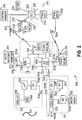
- Figures 1 and 2 are simplified representations of a flexible patient monitoring system constructed in accordance with the present invention.
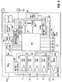
- Figure 3 is a block schematic diagram of a main portion of a multiport telemetry-transmitter featured in Figures 1 and 2.
- Figure 4 is a block schematic diagram of a backchannel receiver module featured in Figures 1 and 2.
- Figure 5 is block schematic diagram of a telemetry docking station featured in Figures 1 and 2.
- The present invention provides increased flexibility in an improved patient monitoring system without requiring significant increase in the size, weight, cost, or battery usage of a telemetry transmitter. As will be understood with reference to Figures 1 and 2, a
telemetry subsystem 100 and a flexiblepatient monitoring system 200 may be constructed according to the present invention. Thetelemetry subsystem 100 include certain ones of the following components, depending upon the mode of patient monitoring to be performed, and the particular environment(s) in which the subsystem is operating: - a
primary monitoring instrument 101 - an
auxiliary monitoring instrument 102 - a multiport transmitter (MPX) 110
- a
telemetry docking station 111 - a telemetry subsystem interface, e.g., a
portable processor 112 orportable computer 114 - a
backchannel receiver module 113 - a
system communications network 205, which includes nodes such as acentral monitoring station 204 - a telemetry
signal receiving system 203 - a
backchannel transmission system 214 - electrocardiogram/respiration (ECG/RESP)
- electrocardiogram (ECG)
- invasive pressures
- temperature
- non-invasive blood pressure (NIBP)
- SpO₂/Pleth level
- carbon dioxide level (CO₂)
- cardiac output
- TcGas
- A first preferred embodiment of the
backchannel receiver module 113 may be incorporated within the MPX 110 (as shown in Figure 1) or, in a second preferred embodiment, may be constructed as a detachable backchannel receiver module 213 (as shown in Figure 2). In a particularly preferred embodiment, thebackchannel receiver module backchannel transmission system 214. Suchbackchannel transmission system 214 includes abackchannel controller 214C,backchannel transmitter 214X, andantenna 214A. - The telemetry subsystem interface is preferably provided in the form of a
portable processor 112, or aportable computer 114. A preferred embodiment of theportable processor 112 is a Hewlett-Packard 200LX palmtop processor. Theportable computer 114 is preferably provided in the form of a notebook computer. A preferred embodiment of theportable computer 114 is a Hewlett-Packard Omnibook superportable computer. - Application software resident on the
portable processor 112 orportable computer 114 provides control and interfacing functions with respect to theMPX 110 transmitter. Software for operating theportable processor 112 or theportable computer 114 may be installed via a plug-in memory module, preferably in the form of a memory card C (such as a PCMCIA card). For example, theportable processor 112 can initiate communication with theMPX 110 transmitter automatically upon program execution and establishment of a communication link for transfer of control and data signals. The contemplated communications link may be effected through a first data port, preferably in the form of anoptical communications transceiver 121 via light beam L, or via anoptical fiber cable 122. Alternatively, a communications link may be effected at a second data port preferably in the form of aserial data interface 123 coupled to a data portion of a multiconductor data and power cable 123A. Power may be transferred to theportable processor 112 via a power cable portion of the multiconductor data andpower cable 123A to aDC input jack 124. - A first preferred embodiment of the
telemetry docking station 111 includes a first data andpower port 120B for connecting power lines P and data paths D1, D2 between thetelemetry docking station 111 and theMPX 110. Power may be supplied to thetelemetry docking station 111 from a permanent power source (e.g., an AC outlet) via an AC/DC converter 125 through apower conditioning circuit 126 and anisolation circuit 127. Additional power lines P and a data path D3 are connected to theportable processor 112 orportable computer 114 via a second data andpower port 128. An additional data path D4 is connected to theprimary monitoring instrument 101 orauxiliary monitoring instrument 102 via afirst data port 132 to which a monitoringinstrument multiconductor cable multiconductor cables - The
isolation circuit 127 provides isolated, conditioned power to theMPX 110,portable processor 112, andportable computer 114, thus providing reliable, isolated power and relieving those units from the need to operate on other power sources, such as internal batteries. Theisolation circuit 127 also provides electrically-isolated transfer of data between theMPX 110,portable processor 112 orportable computer 114, theprimary monitoring instrument 101, and theauxiliary monitoring instrument 102. For portability, thetelemetry docking station 111 is preferably provided in a compact, light, low-profile form factor similar to that of the portable processor 112 (e.g., of dimensions less than or comparable to that of the interior of a coat pocket, at approximately 16 x 9 x 3 centimeters). - As particularly illustrated in Figure 2, a second preferred embodiment of the MPX 210 contains first and second
physiological monitoring sections physiological monitoring section 216A may be connected to thepatient 218 by a sensor 220. For example, for ECG monitoring, the sensor 220 would be connected to electrodes attached to the patient's chest. As will be described below, a certain ones of the conductors in sensor 220 may also be employed as a data communications link 220A to aprimary monitoring instrument 201. - Sense signals derived by the
monitoring sections telemetry processor 222 which preferably includes a suitably-programmed microprocessor for conversion of the sense signals to a suitable telemetry signal for transmission to thecentral monitoring station 204. Thetelemetry processor 222 may also contain signal interface circuitry, signal processing circuitry, a power supply section, and memory sections(s) for storage and retrieval of selected information concerning thepatient 218 or the operation of the MPX 210. Thetelemetry processor 222 is also programmed to perform other processing functions, such as error-checking, self-testing, and the like. - A telemetry signal is output from the
telemetry processor 222 to a frequency-synthesized transmitter 224 for broadcast at asuitable output element 226. Depending on the telemetry needs in the hospital, the transmitter 224 andoutput element 226 may be constructed to radiate at a selected frequency in the radio frequency (RF) band; theoutput element 226 may be integrated into the sensor 220 or may be otherwise situated in the MPX 210. An alternative embodiment of the transmitter 224 andoutput element 226 may be constructed to radiate at a selected frequency in the optical transmission band; for example, an infrared frequency. - The telemetry signal emitted by the
output element 226 is received by one of a plurality of receivingelements 228 andtelemetry receivers 232 suitably located in the hospital. Telemetry signals acquired by the plurality oftelemetry receivers 232 are applied to atelemetry receiver interface 233 for translation to network telemetry data, which is transferred to anetwork controller 230 preferably in the form of a serial communications controller (SCC). The network telemetry data is then transferable to other nodes on thenetwork 205 such as thecentral station 204. Such nodes may be considered local nodes, that is, in locations proximate to thepatient 218, and other nodes may be quite remotely situated. The local nodes on thenetwork 205 are contemplated as including suitable data terminals, workstations, and the like so as to make the network telemetry data available to hospital staff at a network node in a clinical or surgical setting, a physician's office, a hospital pharmacy, a diagnostic laboratory, a data processing and record-keeping center, and similar departments or locations within the hospital. Additional password-protected, secure connections to communications networks outside the hospital, such as telephone and radio networks, allow authorized persons to access the network telemetry data at remote nodes (i.e., nodes located outside of the hospital). - The telemetry network data may be processed at any node on the
network 205. For instance, thecentral monitoring station 204 may perform further processing so as to derive patient information and may selectively store such information in temporary orbulk storage devices 236. Thecentral monitoring station 204 and may cause images indicative of such patient information to be selectively displayed on one or more displays. For instance, medical personnel that have access to thecentral monitoring station 204 may monitor and react to relevant physiological conditions of the patient. - The MPX 210 features an input/output (I/O)
section 240 that operates first, second, and third ports 240A, 240B, 240C. The first port 240A may, for example, be a wireless transceiver data port, such as one including an IR transmitter and complying with the serial infrared (SIR) data transmission protocol designed by the Hewlett-Packard Company. Such a first port would interface with one or more SIR receivers present on theportable processor 212 as described above. The second port 240B may be directly connected to thetelemetry docking station 211 at arespective port 242A and serve as a power and data communications interface between the MPX 210 and thetelemetry docking station 211. The third port 240C may connect to abackchannel receiver module 213 as will be discussed below. - The
telemetry docking station 211 includes a first, second, and third I/O sections respective ports power isolation section 250 and apower conditioning section 252 are connectable to a permanent power source (not shown) such as the hospital main electrical system. The second I/O section 246 serves as a data interface to anauxiliary monitoring instrument 202. The third I/O section 248 andport 248A serve as a data interface operable with an I/O section 256 and port 256A on theportable processor 212. Preferably, theports 248A and 256A are provided in the form of infrared transceiver ports. - The flexible
patient monitoring system 200 may be configured to operate in at least four modes: - 1) ambulatory telemetry mode, wherein the MPX 210 is operated independently of other monitoring instruments and is powered by an internal power source;
- 2) docked telemetry mode, wherein the MPX 210 is connected to a
telemetry docking station 211 for transfer of data and power; - 3) simple instrument telemetry mode, wherein the MPX 210 and a
primary monitoring instrument 201 or anauxiliary monitoring instrument 202 are connected together for transfer of data therebetween, and - 4) docked instrument telemetry mode, wherein the MPX 210 and a
primary monitoring instrument 201 or anauxiliary monitoring instrument 202 are attached to thetelemetry docking station 211 for transfer of data therebetween (and optionally for transfer of power to the MPX 210). - For example, when the MPX 210 is operated in the instrument telemetry mode, an operator can determine at the bedside what primary monitoring data is to be transmitted to the
network 205 by use of an instrument telemetry configuration frame displayed on theprimary monitoring instrument 201. Data will be transferred from theprimary monitoring instrument 201 to the MPX 210, which will receive, multiplex, compress, format, and transmit the data as a telemetry signal to a telemetrysignal receiving system 203. Receivers located in the telemetrysignal receiving system 203 receive the telemetry signal and thetelemetry receiver interface 233 uses appropriate protocols to convert the telemetry signal into network data messages for transmission over thenetwork 205. Theflexible telemetry system 200 can thereby transfer patient monitoring data, control signals, alarm signals, and other information from the MPX 210 (or an instrument connected to the MPX 210) to any node on the network, such as the node occupied by acentral monitoring station 204. - In particular, the MPX 210 can provide a wireless connection of the
portable processor 212, theportable computer 114, theprimary monitoring instrument 201, and/or theauxiliary monitoring instrument 202 to thenetwork 205. Further, data received by theMPX 110 from theportable processor 212, theportable computer 114, theprimary monitoring instrument 201, and/or theauxiliary monitoring instrument 202 may be monitored at the patient's location, without any need for a hard-wired network connection. - Due to its multiplicity of communication ports, the MPX 210 may be easily reconfigured to and from ambulatory mode, docked telemetry mode, simple instrument telemetry mode, or docked instrument telemetry mode. This flexibility allows the flexible
patient monitoring system 200 to be reconfigured while thepatient 218 occupies or moves between any of the hospital areas that are serviced by receivingelements 228. This reconfiguration may be accomplished while still permitting continuous monitoring of relevant patient physiological conditions. As a result, the task of patient monitoring is effected more flexibly and inexpensively, patient bed transfer costs are reduced, and the number and acuity of the patients that are monitored is greater than in a conventional patient monitoring system. - Preferably, the telemetry signal contains status information pertaining to the monitoring mode as well as the type of data being transmitted. The telemetry
signal receiving system 203 includes data acquisition software modules for determining whether the data received is ambulatory telemetry data or instrument telemetry data, and formatting the received telemetry data into a form appropriate for transmission on the network. For instance, thecentral monitoring station 204 may receive telemetry data that has been formatted to cause differing user interfaces to be displayed on the central monitoring station, according to whether the data represents information derived from an ambulatory telemetry mode or an instrument telemetry mode. As a further example, recording requests from theprimary monitoring instrument 201 may be formatted into the various types of recordings supported by different nodes of thenetwork 205. - In some instances of ambulatory mode operation, it may be advantageous to couple the MPX 210 to the
portable processor 212 via IR transceivers in the ports 256A and 240A such that thetelemetry docking station 211 need not be used. The two units (MPX 210 and portable processor 212) may be physically coupled as well, to form a single, portable package. When necessary, anoptical fiber cable 244 may be connected between suitable terminals on theports 240A, 248A, or 256A to effect light-tight transmission between I/O sections 240, 248, or 256. - The
portable processor 212 includes a data output device preferably in the form of a liquid crystal display or some other type offlat screen display 258, a data input device such as akeyboard 260, and a microprocessor section 262. The I/O section 256 may be operated to communicate information to and from the microprocessor 262. Memory sections included in the microprocessor for storing information allows the microprocessor to be programmed to perform selected processing tasks on the received data. For example, a representation of telemetry data acquired from the MPX 210 may be displayed ondisplay 258 and the nature of this representation may be varied by a user according to commands or queries entered on thedata input device 260. The user may select from a variety of a representations, including ECG waveforms, a transmitter frequency chart, trend graphs, or other useful information. While not specifically indicated in Figure 2, theportable processor 212 is contemplated as incorporating or accommodating other forms of data input devices such as a microphone, roller ball, touch screen, pen-based input panel, or the like. Similarly, theportable processor 212 may incorporate other forms of data output devices, such as an annunciator for sounding an audible signal, or acoustic transducer for reproducing a voice. Components for carrying out the performance of other processing tasks (not shown) may be included in theportable processor 212 as known in the art, such as extended memory cards, facsimile/modem cards, and the like. - Keyboard inputs, either as generated, or as modified by processor 262, may be applied through I/O port 256 to I/
O port 242, and from I/O port 240 to thetelemetry processor 222 Such inputs may, for example, represent commands to change the mode of ECG monitoring by themonitor sections monitor sections monitoring sections telemetry processor 222 according to commands inputted fromkeyboard 260. Data entered atkeyboard 260 may also be passed through processor 262, I/O sections telemetry processor 222 to transmitter 224 for transmission to thecentral monitoring station 204. Such data may be utilized, for example, to effect diagnostic routines on one or more of the components of theflexible monitoring system 200. - A
backchannel receiver module 213 is detachably mounted on the MPX 210, preferably at port 240C. Thebackchannel receiver module 213 includes a communications and power port 213A, abackchannel receiver 270, and receivingantenna 272. Data originating from any node on thenetwork 205 may be directed to thebackchannel communications controller 214C for addressable transmission to a particularbackchannel receiver module 213. That is, each message sent bybackchannel transmitter 214X would include an encoded address so that it is received and/or utilized only by thebackchannel receiver module 213 for which it is intended. Once received and translated, the message is provided to the I/O section 240 of the MPX 210. - The
backchannel receiver 270 may operate on an integral battery power source and alternatively may be operated via power provided through the communications and power port 213A; such power may originate from the MPX 210 or from thetelemetry docking station 211. The requisite circuitry and components that comprise thebackchannel receiver 270 and receivingantenna 272 may be constructed in a package that is extremely compact, light in weight, and consumes very little power according to known telecommunications receiver technology. - The attachment of the
backchannel receiver module 213 to the MPX 210 permits medical personnel at a node on the network 205 (e.g., acentral monitoring station 204 or similar terminal) to enter information (e.g., data or commands) on an appropriate input device, and direct the information via thebackchannel transmission system 214 to the MPX 210 or theportable processor 212. Such communication may, for example, be in response to inputs or queries from attending staff that were inputted onkeyboard 260. Similarly, other monitoring instruments, data processing or storage equipment, and other control and communications equipment connected to thenetwork 205 may communicate with thebackchannel receiver module 213. - As mentioned in the above, the particularly preferred embodiment of the
backchannel receiver module 213 is constructed to support a communications backchannel via a paging transmission system. Most communities already employ one or more "wide-area" paging transmission systems to communicate with portable, pocket-sized receivers known as pagers. Accordingly, thebackchannel receiver module 213 is constructed to take advantage of any pre-existing paging transmission system so as to provide inexpensive, two-way communication between thenetwork 205 and the MPX 210. In particular, most hospitals already employ at least one "local-area" paging system that has been installed and dedicated for hospital use, and many hospital staff members carry a pager. Because the hospital staff members are already carryingportable processors 212 andportable computers 114 for other purposes, and will increasingly do so in the future, the benefits of the present invention are achieved without the significant expense of additional equipment and without any significant change in the way such hospitals and personnel are already operating. - Further, it is a particular feature of the present invention that dynamic control may be effected of the system configuration and of the patient monitoring features and functions performed by the
flexible monitoring system 200. Some of such functions may heretofore have required user intervention and/or reconfiguration of one or more of components of a conventional patient monitoring system. For the purposes of this description, dynamic control is meant to describe network-based, system-originated control of one or more of the features, functions, or tasks performed by theflexible monitoring system 200. Such features, functions, or tasks include:
Service modes, such as a remote reading of: the status of the power available to the MPX 210 ortelemetry docking station 211, the signal strength of the backchannel transmitter (as received by the backchannel receiver module 213), the frequency or signal strength of the transmitter 224 in the MPX 210, or the physiological conditions currently being monitored (ECG, SpO₂, etc.). The service mode information may be acquired only on demand, so that the telemetry transmission bandwidth may be conserved for transmitting patient data. A particular service mode contemplated by the invention includes the transmission of new PROM code from a node on thenetwork 205 via thebackchannel transmission system 214 and thebackchannel receiver module 213 for downloading into a memory device (such as anEEPROM 354 illustrated in Figure 3).
Query the MPX Configuration, wherein a network node may query the MPX 210 for configuration data and settings, such as thresholds or other measurements (i.e. notch filter, SpO₂ sample rate, and frequency channel) or system information (i.e. firmware/hardware revision numbers and serial number), or to view or to edit such records as a status log. Alternatively, hospital personnel may also use theportable processor 212 to receive and answer a system-initiated query, and see the system's response.
Delivery of alarms or messages to the patient or attending staff by provision of an alarm signal (e.g. a tone) or a voice signal through a transducer on the MPX 210 orportable processor 212, or by display of textual messages on thedisplay 258 of theportable processor 212.
Determination of the location of the MPX (and hence location of the patient) via transmission of signals from a plurality ofbackchannel transmission systems 214 each of which are spatially separated at fixed, known locations within the hospital, followed by measurement of the strength and delay of the signals.
Lead selection and transmitter lead fallback may be accomplished at thetelemetry processor 212 before data is sent from the MPX 210. This feature also conserves the bandwidth required to transmit telemetry data, allows the MPX to transmit other parameters, or to improve forward error correction.
Redundant transmission of information, such as transmission of a waveform with 100% redundancy, thus enabling the system to compensate for dropouts in a telemetry transmission caused by multipath fading.
Dynamic power control of the radiated power level of the transmitter 224, according to the transmission path power loss. Rather than transmitting at a high enough power to overcome worst case losses, activation of this feature allows the average power consumption to be minimized, thus substantially extending battery life.
Diversity selection allows a network node to command the transmitter 224 to transmit on one of two spatially separated versions of theoutput element 226, e.g., either an antenna integrated in the sensor 220 and another antenna imbedded in the housing of the MPX 210.
Reuse of a selected transmission frequency by assigning a single frequency to more than one MPX 210. Such reuse is contemplated as being effected by spatial (cellular) allocation of a frequency, wherein eachMPX 211 is located sufficiently distant from the others so as to overcome any channel interference. Such reuse is also contemplated as including time division multiplexing of the data transmitted from more than oneMPX 211 onto one transmission channel. This feature dramatically increases the number of channels that onetelemetry receiver 232 can service, and allows the flexiblepatient monitoring system 200 to monitor a large numbers of patients per transmission channel, and reduces errors that are caused by channel interference.
Selection of the transmission frequency (transmission channel), an otherwise costly and time consuming process, so as to change the frequency of the transmitter 224 without user intervention.
Error control according to data exchange protocols so as to correct short term dropouts (due to multipath fading). For example, the MPX 210 may send a message, then wait for a return message from thebackchannel controller 214C acknowledging proper receipt. The MPX 210 may repeat the message if no acknowledgment is received. - Figure 3 shows an overall block diagram of a preferred embodiment of a
main board 300 operable in the signal processing anddata transmission section 119 of theMPX 110. Themain board 300 may be considered to include five subsections: a set of ECG front ends, a SpO₂ monitor, an application specific integrated circuit (ASIC), a digital signal processor (DSP), and a power supply section. - The
ASIC 310 is operable with at least four external signal interfaces (not including the output of transmitter 224). First and secondsignal interface lines 311 connect to thetelemetry docking station 211; a third interface line 313 connects to a serial infrared port (SIR) 315 and the fourth interface line 314 connects to a sensor interface driver 318 (preferably in the form of a serial data port driver) which may be used to communicate to theprimary monitoring instrument 201 through two leads (RA, RL) of the patient sensor (V, RA, LL, LA, RL). TheASIC 310 preferably contains universal asynchronous receiver-transmitters for performing these functions. - The serial
infrared port 315 communicates using a subset of the SIR protocol. This port can be "aimed" at theportable processor 212 for establishing an unguided optical communications link, or can be attached to thefiber optic cable 244 for a more robust optical connection. Such a connection facilitates the physical coupling of theportable processor 212 and the MPX 210 for combined use during ambulatory telemetry mode. - In a particular feature of the invention, the
sensor interface 318 insures patient safety by prohibiting an electrical path from a non-battery powered instrument, such as theprimary monitoring instrument 201 orauxiliary monitoring instrument 202, through the MPX 210 to the patient. Also, thesensor interface 318 will sense a voltage on one of the conductors in the connection to theprimary monitoring instrument 201; theASIC 310 will only connect a serial data driver to the patient leads when it senses this voltage. This insures that there is no harm to the patient by inadvertent application of serial data to the sensor, which may be already connected to the patient. - An
SpO₂ monitoring section 321 produces data representative of the arterial oxygen saturation value, the pulse rate, and relative perfusion. TheSpO₂ monitoring section 321 will connect directly to an appropriate SpO₂ sensor (not shown) such as may be obtained from Hewlett-Packard Company, Nellcor, or Ohmeda. - Additional circuitry connected to the
ASIC 310 include: four ECG front ends 331, 332, 333, 334; abattery 343; a SpO₂ monitorpower supply circuit 344; a mainpower supply circuit 346; abattery sense circuit 348; a transmitter power supply circuit 352; a programmable memory storage device preferably in the form of an electrically-erasable programmable read-only memory (EEPROM)chip 354; a digital signal processor (DSP) chip 356; a static memory storage device, preferably in the form of a static random access memory (SRAM) 358; a radio-frequency (RF) modulator 362; and aradio frequency synthesizer 364. Also connected to theASIC 310 are a set of leads-off indicators, each preferably in the form of a light-emitting diode (LED)array 366, and a RLlead driver circuit 368. TheASIC 310 handles the task of interfacing to the ECG hardware, the nurse call button, the leads off indicators; and theASIC 310 controls signals to and from theSpO₂ circuit 321, theprimary monitoring instrument 201 , theSIR port 315, and the two serial port lines 311. - The
EEPROM 354 preferably contains frequency, patient identification, and system configuration information. By performing all data processing tasks in the DSP 356, which is set to by direct boot from theEEPROM 354, future software upgrades are made easily through the serial port lines 311. - Additional main board hardware architecture includes:
Nurse Call Button: A signal on a nursecall button line 372 may be configured to cause theASIC 310 to run a recording, set off the nurse call alarm, or perform another communication function such as what is known as spoof coding, which may be used by a technician to match a MPX 210 to atelemetry receiver 232.
Power Supply Control: Control lines from theASIC 310 may be operated to selectively shut down certain power subsections, as will be described below.
Internal Power Source: Preferably, abattery 343 is a Alkaline, Zinc-Air, or Carbon-Zinc 8.4 or 9 volt battery for use when the MPX 210 is not configured to monitor SpO₂ ; when SpO₂ is used, a lithium battery is preferred.
Visual indicators: Five indicators preferably in the form oflight emitting diodes 366 are situated on the exterior of the MPX 210 with each indicator located under the respective electrode that corresponds to a lead. TheDSP 342 activates an appropriate indicator after a change of state (e.g., leads-off condition) in any lead wire. Also, some or all of the LEDs may be activated in a predetermined pattern to indicate that the MPX fails a self-test, or to indicate the signal strength received by theSIR 315.
Power Supply: The mainpower supply section 346 is a linear or switch mode power supply that converts power from thebattery 343 for provision to the SpO₂power supply subsection 344, transmitter power supply subsection 352, andbattery sense subsection 348. Additionally, the MPX 210 may source power from thetelemetry docking station 211 or the sensor 220 via diodes that are connected to the mainpower supply section 346. For example, when theprimary monitoring instrument 201 is employed in instrument telemetry mode and power from thebattery 343 is to be conserved, the presence of a minimum of 9V on the shield of the RL lead causes themain power supply 346 to draw its power from the sensor 220. Patient isolation is achieved by preventing simultaneous connections to both the patient and to power from theprimary monitoring instrument 201
Battery Sense Section: Thebattery sense section 348, under control of theASIC 310, effects control of all of the power supply subsections. For example, the SpO₂ monitoring, transmitter, ECG monitoring, or communications functions may be individually shut down by theASIC 310 to conserve power. TheASIC 310 also provides, based on signals from the battery sense section, advance warning messages that are displayed on thenetwork 205 or thedisplay 258, such as "replace battery" or "weak battery". - Figure 4 illustrates a particularly preferred
embodiment 402 of thebackchannel receiver module 213 of Figure 2. The pagingbackchannel receiver module 402 preferably receives frequency-modulated (FM) transmissions at certain paging transmission frequencies, which currently include frequencies in the range of 30 -50 megahertz (mHz), 150-174 mHz, 450-512 mHz, or 800-1000 mHz. These transmissions are received by an antenna 604 that is preferably integrally mounted on thebackchannel receiver module 402, and filtered by aRF filter stage 406 before being passed to amixer 408. The output of anoscillator 410 mixed with the filtered RF signal is output to an intermediate frequency (IF)filter stage 412. The IF filtered signal is then passed to a limiter/demodulator stage 414 and adecoding stage 416. The decoded signal output is provided to adata transfer stage 418 for transfer through a data and power connector 420 to the MPX 210. - With reference to Figure 5, a preferred embodiment of the data and
power handling circuitry 502 of thetelemetry docking station 211 will be understood to include : a) first and second datacommunication interface sections portable processor 212 and one or more monitoring instruments, such as theprimary monitoring instrument 201 and an auxiliary monitoring instrument 202); b) apower conversion section 520 and apower transformer section 622 to enable units such as the MPX 210 orportable processor 212 to receive isolated, regulated power from external power sources; and c) adata processing section 524 preferably in the form of a microprocessor for performing data protocol translation and other data interfacing functions. Thetelemetry docking station 211 preferably incorporates microminiature components and circuitry so as to provide the aforementioned functions in a compact, portable unit that is positionable adjacent, or attachable to, theportable processor 212 and/or theportable computer 114. - A DC
input power jack 504 preferably receives 12VDC from a conventional AC-to-DC wall outlet converter, certified as an IEC-601-1 medically approved device, such as are commercially available for powering portable medical electronic devices. A DC outjack 506 provides 12VDC to theportable processor 212. A firstserial interface circuit 511 and a secondserial interface circuit 512 have respective connections RXA, TXA and RXB, TXB. The first andsecond interface circuits optocouplers - The received 12VDC power from the charger is passed through first and second
linear regulators oscillator 534 and to first and second field-effect transistor (FET) stages 536, 538 before being fed to the primary sides of first andsecond transformers Linear regulators transformers
8V -- transformer primaries
5V -- power tooscillator 534
8VA - isolated power to the MPX 210
5VA - isolated power to local side ofoptocouplers
5VB - Isolated power to remote side ofoptocoupler 521
5VC - Isolated power to remote side ofoptocoupler 522
This illustrated circuit uses thetransformers telemetry docking station 211 thus provides these features: - a. power line isolation by the use of an IEC-601-1 medically-approved wall charger;
- b. patient isolation by use of isolated power supplies;.
- c. serial data optical isolation;
- d. defibrillation isolation, by employing recessed pins in all external connectors on the MPX 210.
- While the invention has been particularly shown and described above with reference to preferred embodiments, changes in form and detail may be made by one skilled in the art to the foregoing embodiments without departing from the spirit and scope of the invention.
-
- C
- memory card
- D
- data path
- L
- light beam
- P
- power path
- 101
- primary monitoring instrument
- 102
- auxiliary monitoring instrument
- 110
- multiport transmitter (MPX)
- 111
- telemetry docking station
- 112
- portable processor
- 113
- backchannel receiver module
- 114
- portable computer
- 116
- nurse call button
- 117
- serial infrared (SIR) port
- 118
- sensor system
- 119
- data processing and signal transmission section
- 120A
- power and data port
- 120B
- power and data port
- 121
- optical communications transceiver
- 122
- optical fiber cable
- 123
- data port
- 123A
- power and data cable
- 124
- power input jack
- 125
- AC/DC converter
- 126
- power conditioning circuit
- 127
- isolation circuit
- 128
- computer power & data port
- 131A
- monitoring instrument multiconductor cables
- 131B
- 201
- bedside monitor
- 202
- auxiliary monitoring instrument
- 203
- telemetry receiving system
- 204
- central monitoring station
- 205
- communications network
- 210
- multiport transmitter (MPX)
- 211
- telemetry docking station
- 212
- portable processor
- 213
- backchannel receiver module
- 213A
- communications and power port
- 214
- backchannel transmission system
- 214A
- backchannel antenna
- 214C
- backchannel communications controller
- 214X
- backchannel transmitter
- 216A
- first monitoring section
- 216B
- second monitoring section
- 218
- patient
- 220
- lead set
- 222
- telemetry processor
- 224
- frequency-synthesized transmitter
- 226
- output element
- 228
- receiving elements
- 230
- network controller
- 232
- telemetry receiver
- 233
- telemetry receiver interface
- 240
- I/O section
- 240A
- serial infrared (SIR)
- 240B
- serial port
- 240C
- serial port
- 242
- first I/O section
- 244
- optical cable
- 248
- second I/O section
- 250
- power isolation section
- 252
- power conditioning section
- 256
- I/O section (portable processor)
- 258
- display device
- 260
- keyboard
- 262
- microprocessor
- 270
- backchannel receiver
- 272
- receiving antenna
- 310
- application-specific integrated circuit (ASIC)
- 311
- serial port lines
- 312
- connector, PCMCIA
- 313
- SIR line
- 315
- SIR port
- 318
- sensor interface
- 321
- SPO₂ monitoring circuit
- 331
- ECG front ends
- 343
- battery
- 344
- SPO₂ power supply subsection
- 346
- main power supply
- 348
- battery sense subsection
- 352
- transmitter power supply subsection
- 354
- electrically-erasable programmable read-only memory (EEPROM)
- 356
- digital signal processor (DSP)
- 358
- static random access memory (SRAM)
- 362
- radio frequency (RF) modulator
- 364
- frequency synthesizer
- 366
- LED's
- 368
- RL driver circuit
- 372
- nurse call button line
- 402
- paging backchannel receiver module
- 404
- antenna
- 406
- RF filter stage
- 408
-
mixer 408 - 410
- oscillator
- 412
- intermediate frequency (IF) filter
- 414
- limiter/demodulator stage
- 416
- decoding stage
- 418
- data transfer stage
- 420
- data and power connector
- 502
- data and power handling circuitry
- 504
- DC input jack
- 506
- DC output jack
- 511
- first serial interface circuit
- 512
- second serial interface circuit
- 520
- power conversion section
- 522
- power transformer section
- 524
- data processing section
- 531
- first linear regulator
- 532
- second linear regulator
- 534
- oscillator
- 536
- first field effect transistor (FET)
- 538
- second FET
- 541
- first transformer primary
- 542
- second transformer primary
- 543
- - linear regulators
- 546
Claims (10)
- A system for providing dynamic control of a patient monitoring function, comprising:
a communications network (205) having a plurality of nodes;
a backchannel transmission system (214) connected to a one of said nodes for receiving the dynamic control information and for transmitting the dynamic control information in a backchannel transmission;
a multiport transmitter (110;210) including a data processing section (119;222) for carrying out the patient monitoring function, and
a backchannel receiver module (113;213) for receiving the backchannel transmission, translating the received transmission to provide respective dynamic control information, and providing the dynamic control information to the data processing section (119;222);
wherein the data processing section (119;222) implements the dynamic control information to alter the patient monitoring function. - The system of claim 1, wherein the multiport transmitter (110;210) further comprises:
a sensor system (118;220) connectable to the patient (218) for providing a sense signal representative of a first physiological condition;
a monitoring section (321) for receiving the sense signal and providing first data representative of the first physiological condition;
a first data port (117;240A) for receiving externally-sourced data, whereby the first data and the externally-sourced data are processed by the data processing section (119;222) to provide processed data;
a dynamic memory storage device (354) for storing programmed information relative to the operation of the data processing section;
a power supply section (343,344,346,348,352); and
a transmitter (224) for transmitting the processed data as a telemetry signal. - A system as claimed in claim 2, wherein said dynamic control information is applied to alter the operation of the transmitter (224).
- A system as claimed in claim 3, wherein the transmitter (224) is a frequency-synthesized transmitter and the dynamic control is applied to alter the operating frequency of the transmitter (224).
- A system as claimed in claim 2, wherein said dynamic control information is applied to change the mode of operation of the monitoring section (321).
- A system as claimed in claim 5, wherein said dynamic control information is applied to select one of a plurality of physiological parameters.
- A system as claimed in claim 2, wherein said dynamic control information is applied to alter the programmed information relative to the operation of the data processing section (119;222).
- A system as claimed in claim 2, wherein said dynamic control information is applied to alter the operation of the power supply section (343,344,346,348,352).
- A system as claimed in claim 2, wherein said dynamic control information is applied to select between the processing of the first data and the externally-sourced data in providing the processed data.
- A system as claimed in claim 2, further comprising a central monitoring station (204) connected to another of said nodes, and wherein the dynamic control information is originated at the central monitoring station (204).
Applications Claiming Priority (2)
| Application Number | Priority Date | Filing Date | Title |
|---|---|---|---|
| US326615 | 1994-10-20 | ||
| US08/326,615 US5579775A (en) | 1994-10-20 | 1994-10-20 | Dynamic control of a patient monitoring system |
Publications (1)
| Publication Number | Publication Date |
|---|---|
| EP0710465A1 true EP0710465A1 (en) | 1996-05-08 |
Family
ID=23272969
Family Applications (1)
| Application Number | Title | Priority Date | Filing Date |
|---|---|---|---|
| EP95111099A Withdrawn EP0710465A1 (en) | 1994-10-20 | 1995-07-14 | Dynamic control of a patient monitoring system |
Country Status (3)
| Country | Link |
|---|---|
| US (1) | US5579775A (en) |
| EP (1) | EP0710465A1 (en) |
| JP (1) | JPH08214379A (en) |
Cited By (12)
| Publication number | Priority date | Publication date | Assignee | Title |
|---|---|---|---|---|
| WO1998000056A1 (en) * | 1996-07-02 | 1998-01-08 | Vitalcom, Inc. | Architecture for tdma medical telemetry system |
| GB2349283A (en) * | 1999-04-17 | 2000-10-25 | Data Acquisition Systems Ltd | Isolated power supply for a peripheral device coupled to a computer |
| WO2000062867A1 (en) * | 1999-04-16 | 2000-10-26 | Technogym S.R.L. | A telecommunication system for exchanging physiological state information between a physical person and an information system |
| WO2000062866A1 (en) * | 1999-04-16 | 2000-10-26 | Technogym S.R.L. | A telecommunication system for exchanging confidential information between a physical person and an information system |
| WO2001064098A1 (en) * | 2000-03-01 | 2001-09-07 | Technogym S.P.A. | An expert system for the interactive exchange of information between a user and a dedicated information system |
| WO2002003349A1 (en) * | 2000-07-06 | 2002-01-10 | Daniel Groos | Module network and method for processing data |
| US6409661B1 (en) | 1997-03-08 | 2002-06-25 | Remote Diagnostic Technologies Limited | Diagnostic apparatus |
| WO2001070103A3 (en) * | 2000-03-17 | 2002-08-22 | Medtronic Inc | Heart failure monitor quick look summary for patient management systems |
| EP1262144A1 (en) * | 1996-01-17 | 2002-12-04 | CME Telemetrix Inc. | Spread spectrum telemetry of physiological signals |
| US7831301B2 (en) | 2001-03-16 | 2010-11-09 | Medtronic, Inc. | Heart failure monitor quicklook summary for patient management systems |
| US8115635B2 (en) | 2005-02-08 | 2012-02-14 | Abbott Diabetes Care Inc. | RF tag on test strips, test strip vials and boxes |
| WO2013015815A1 (en) * | 2011-07-28 | 2013-01-31 | Draeger Medical Systems, Inc. | Noise isolator for a portable electronic device |
Families Citing this family (133)
| Publication number | Priority date | Publication date | Assignee | Title |
|---|---|---|---|---|
| US7624028B1 (en) | 1992-11-17 | 2009-11-24 | Health Hero Network, Inc. | Remote health monitoring and maintenance system |
| AU1766201A (en) | 1992-11-17 | 2001-05-30 | Health Hero Network, Inc. | Method and system for improving adherence with a diet program or other medical regimen |
| US5307263A (en) | 1992-11-17 | 1994-04-26 | Raya Systems, Inc. | Modular microprocessor-based health monitoring system |
| US6968375B1 (en) | 1997-03-28 | 2005-11-22 | Health Hero Network, Inc. | Networked system for interactive communication and remote monitoring of individuals |
| US20010011224A1 (en) | 1995-06-07 | 2001-08-02 | Stephen James Brown | Modular microprocessor-based health monitoring system |
| DE4329898A1 (en) | 1993-09-04 | 1995-04-06 | Marcus Dr Besson | Wireless medical diagnostic and monitoring device |
| US5664270A (en) * | 1994-07-19 | 1997-09-09 | Kinetic Concepts, Inc. | Patient interface system |
| US5919141A (en) * | 1994-11-15 | 1999-07-06 | Life Sensing Instrument Company, Inc. | Vital sign remote monitoring device |
| JPH0947436A (en) * | 1995-08-09 | 1997-02-18 | Noboru Akasaka | Home medical system |
| US5942986A (en) * | 1995-08-09 | 1999-08-24 | Cedars-Sinai Medical Center | System and method for automatic critical event notification |
| US5687717A (en) * | 1996-08-06 | 1997-11-18 | Tremont Medical, Inc. | Patient monitoring system with chassis mounted or remotely operable modules and portable computer |
| EP1011420B1 (en) | 1996-09-19 | 2004-12-08 | Ortivus Aktiebolag | Portable telemedicine device |
| US5959529A (en) | 1997-03-07 | 1999-09-28 | Kail, Iv; Karl A. | Reprogrammable remote sensor monitoring system |
| AU9570198A (en) * | 1997-09-16 | 1999-04-05 | Kinetic Concepts, Inc. | Critical care management system incorporating remote imaging and telemetry |
| US6024699A (en) * | 1998-03-13 | 2000-02-15 | Healthware Corporation | Systems, methods and computer program products for monitoring, diagnosing and treating medical conditions of remotely located patients |
| US6477424B1 (en) * | 1998-06-19 | 2002-11-05 | Medtronic, Inc. | Medical management system integrated programming apparatus for communication with an implantable medical device |
| US7612999B2 (en) * | 1998-09-18 | 2009-11-03 | Flo Healthcare Solutions, Llc | Mobile clinical workstation |
| US6167258A (en) * | 1998-10-09 | 2000-12-26 | Cleveland Medical Devices Inc. | Programmable wireless data acquisition system |
| US6125296A (en) * | 1998-10-16 | 2000-09-26 | Northeast Monitoring Inc. | Electrocardiographic and oxygen saturation signal recording |
| US6870484B1 (en) | 1999-03-24 | 2005-03-22 | Ge Marquette Medical Systems, Inc. | Patient monitoring systems having two-way communication |
| US6416471B1 (en) | 1999-04-15 | 2002-07-09 | Nexan Limited | Portable remote patient telemonitoring system |
| US6494829B1 (en) * | 1999-04-15 | 2002-12-17 | Nexan Limited | Physiological sensor array |
| US6454708B1 (en) | 1999-04-15 | 2002-09-24 | Nexan Limited | Portable remote patient telemonitoring system using a memory card or smart card |
| US6385473B1 (en) | 1999-04-15 | 2002-05-07 | Nexan Limited | Physiological sensor device |
| US6450953B1 (en) | 1999-04-15 | 2002-09-17 | Nexan Limited | Portable signal transfer unit |
| US6458326B1 (en) | 1999-11-24 | 2002-10-01 | Home Diagnostics, Inc. | Protective test strip platform |
| DE19961156A1 (en) * | 1999-12-17 | 2001-07-05 | Grieshaber Vega Kg | Level measuring device and method for operating such a level measuring device |
| US6853310B2 (en) | 1999-12-29 | 2005-02-08 | Ge Medical Systems Information Technologies, Inc. | Tri-mode medical telemetry antenna system |
| US6556630B1 (en) | 1999-12-29 | 2003-04-29 | Ge Medical Systems Information Technologies | Dual band telemetry system |
| KR100334892B1 (en) * | 2000-01-06 | 2002-05-02 | 강동주 | Ultrasonic detector using wireless communication and remote diagnosing system using the same |
| US6980958B1 (en) * | 2000-01-11 | 2005-12-27 | Zycare, Inc. | Apparatus and methods for monitoring and modifying anticoagulation therapy of remotely located patients |
| AU2001261198A1 (en) | 2000-05-05 | 2001-11-20 | Hill-Rom Services, Inc. | Patient point of care computer system |
| US6876303B2 (en) | 2000-05-05 | 2005-04-05 | Hill-Rom Services, Inc. | Hospital monitoring and control system and method |
| USRE41236E1 (en) | 2000-07-05 | 2010-04-20 | Seely Andrew J E | Method and apparatus for multiple patient parameter variability analysis and display |
| US6659947B1 (en) * | 2000-07-13 | 2003-12-09 | Ge Medical Systems Information Technologies, Inc. | Wireless LAN architecture for integrated time-critical and non-time-critical services within medical facilities |
| US6572544B1 (en) * | 2000-10-19 | 2003-06-03 | Reynolds Medical Limited | Body monitoring apparatus |
| US6749566B2 (en) | 2001-02-14 | 2004-06-15 | Draeger Medical Systems, Inc. | Patient monitoring area network |
| US6525330B2 (en) | 2001-02-28 | 2003-02-25 | Home Diagnostics, Inc. | Method of strip insertion detection |
| US6562625B2 (en) | 2001-02-28 | 2003-05-13 | Home Diagnostics, Inc. | Distinguishing test types through spectral analysis |
| US6541266B2 (en) | 2001-02-28 | 2003-04-01 | Home Diagnostics, Inc. | Method for determining concentration of an analyte in a test strip |
| AU2002256048A1 (en) | 2001-03-30 | 2002-10-15 | Hill-Rom Services, Inc. | Hospital bed and network system |
| DE10214459A1 (en) * | 2001-04-05 | 2003-04-30 | Univ Ilmenau Tech | Arrangement and method for the detection of signals of biological origin |
| US6801137B2 (en) * | 2001-04-23 | 2004-10-05 | Cardionet, Inc. | Bidirectional communication between a sensor unit and a monitor unit in patient monitoring |
| US20050119580A1 (en) | 2001-04-23 | 2005-06-02 | Eveland Doug C. | Controlling access to a medical monitoring system |
| US6664893B1 (en) | 2001-04-23 | 2003-12-16 | Cardionet, Inc. | Method for controlling access to medical monitoring device service |
| US6665385B2 (en) | 2001-04-23 | 2003-12-16 | Cardionet, Inc. | Medical monitoring system having multipath communications capability |
| US6694177B2 (en) | 2001-04-23 | 2004-02-17 | Cardionet, Inc. | Control of data transmission between a remote monitoring unit and a central unit |
| US7038588B2 (en) * | 2001-05-04 | 2006-05-02 | Draeger Medical Infant Care, Inc. | Apparatus and method for patient point-of-care data management |
| US6970097B2 (en) * | 2001-05-10 | 2005-11-29 | Ge Medical Systems Information Technologies, Inc. | Location system using retransmission of identifying information |
| KR20010070888A (en) * | 2001-06-18 | 2001-07-27 | 이승호 | Real-time medical examination system |
| AP2004002960A0 (en) * | 2001-06-19 | 2004-03-31 | Digital Sports Media | Physiological monitoring and system |
| US7933642B2 (en) | 2001-07-17 | 2011-04-26 | Rud Istvan | Wireless ECG system |
| US6600421B2 (en) * | 2001-07-31 | 2003-07-29 | Koninklijke Philips Electronics N.V. | System to automatically locally control a device according to preferences of a user entering a local area of the device from a remote area |
| US7154397B2 (en) | 2001-08-03 | 2006-12-26 | Hill Rom Services, Inc. | Patient point-of-care computer system |
| US6668182B2 (en) | 2002-01-10 | 2003-12-23 | Northeast Monitoring | Pulse oxymetry data processing |
| US6957107B2 (en) | 2002-03-13 | 2005-10-18 | Cardionet, Inc. | Method and apparatus for monitoring and communicating with an implanted medical device |
| US7062251B2 (en) * | 2003-03-05 | 2006-06-13 | University Of Florida Research Foundation, Inc., | Managing critical care physiologic data using data synthesis technology (DST) |
| US7070566B2 (en) * | 2003-03-13 | 2006-07-04 | Ge Medical Systems Information Technologies, Inc. | Artifact rejection using pulse quality values |
| AU2004224345B2 (en) | 2003-03-21 | 2010-02-18 | Welch Allyn, Inc. | Personal status physiologic monitor system and architecture and related monitoring methods |
| US7500950B2 (en) | 2003-07-25 | 2009-03-10 | Masimo Corporation | Multipurpose sensor port |
| EP1665479A4 (en) | 2003-08-21 | 2008-01-23 | Hill Rom Services Inc | Plug and receptacle having wired and wireless coupling |
| CA2560294C (en) * | 2004-03-18 | 2014-05-27 | Helicor Inc. | Methods and devices for relieving stress |
| GB2413725A (en) * | 2004-04-28 | 2005-11-02 | Agilent Technologies Inc | Network switch monitoring interface translates information from the switch to the format used by the monitoring system |
| US7123137B2 (en) * | 2004-06-28 | 2006-10-17 | Clarian Health Partners, Inc. | Patient safety and alerting system |
| US7319386B2 (en) | 2004-08-02 | 2008-01-15 | Hill-Rom Services, Inc. | Configurable system for alerting caregivers |
| US7502498B2 (en) | 2004-09-10 | 2009-03-10 | Available For Licensing | Patient monitoring apparatus |
| US20060155589A1 (en) * | 2005-01-10 | 2006-07-13 | Welch Allyn, Inc. | Portable vital signs measurement instrument and method of use thereof |
| AU2006204886B2 (en) * | 2005-01-13 | 2011-08-04 | Welch Allyn, Inc. | Vital signs monitor |
| US8002711B2 (en) | 2005-03-18 | 2011-08-23 | Respironics, Inc. | Methods and devices for relieving stress |
| EP2471451A1 (en) | 2005-10-14 | 2012-07-04 | Nanostim, Inc. | Leadless cardiac pacemaker and system |
| US9168383B2 (en) | 2005-10-14 | 2015-10-27 | Pacesetter, Inc. | Leadless cardiac pacemaker with conducted communication |
| US7420472B2 (en) | 2005-10-16 | 2008-09-02 | Bao Tran | Patient monitoring apparatus |
| US7733224B2 (en) | 2006-06-30 | 2010-06-08 | Bao Tran | Mesh network personal emergency response appliance |
| US7686768B2 (en) | 2005-11-23 | 2010-03-30 | Vital Sensors Holding Company, Inc. | Implantable pressure monitor |
| US7682313B2 (en) * | 2005-11-23 | 2010-03-23 | Vital Sensors Holding Company, Inc. | Implantable pressure monitor |
| US7990382B2 (en) | 2006-01-03 | 2011-08-02 | Masimo Corporation | Virtual display |
| EP1815784A1 (en) | 2006-02-06 | 2007-08-08 | Mashhour Mustafa Moh'd Bani Amer | System with intelligent cable-less transducers for monitoring and analysing biosignals |
| US9060683B2 (en) | 2006-05-12 | 2015-06-23 | Bao Tran | Mobile wireless appliance |
| US7539532B2 (en) | 2006-05-12 | 2009-05-26 | Bao Tran | Cuffless blood pressure monitoring appliance |
| US8968195B2 (en) | 2006-05-12 | 2015-03-03 | Bao Tran | Health monitoring appliance |
| US7558622B2 (en) | 2006-05-24 | 2009-07-07 | Bao Tran | Mesh network stroke monitoring appliance |
| US8323189B2 (en) | 2006-05-12 | 2012-12-04 | Bao Tran | Health monitoring appliance |
| US8684922B2 (en) | 2006-05-12 | 2014-04-01 | Bao Tran | Health monitoring system |
| US8500636B2 (en) | 2006-05-12 | 2013-08-06 | Bao Tran | Health monitoring appliance |
| US7539533B2 (en) | 2006-05-16 | 2009-05-26 | Bao Tran | Mesh network monitoring appliance |
| US8684900B2 (en) | 2006-05-16 | 2014-04-01 | Bao Tran | Health monitoring appliance |
| US10188348B2 (en) | 2006-06-05 | 2019-01-29 | Masimo Corporation | Parameter upgrade system |
| US9820658B2 (en) | 2006-06-30 | 2017-11-21 | Bao Q. Tran | Systems and methods for providing interoperability among healthcare devices |
| WO2008004205A1 (en) * | 2006-07-05 | 2008-01-10 | Elcam Medical Agricultural Cooperative Association Ltd. | Wireless medical monitoring system |
| US7880626B2 (en) | 2006-10-12 | 2011-02-01 | Masimo Corporation | System and method for monitoring the life of a physiological sensor |
| US8214007B2 (en) * | 2006-11-01 | 2012-07-03 | Welch Allyn, Inc. | Body worn physiological sensor device having a disposable electrode module |
| US8750971B2 (en) | 2007-05-24 | 2014-06-10 | Bao Tran | Wireless stroke monitoring |
| US7857222B2 (en) | 2007-08-16 | 2010-12-28 | Hand Held Products, Inc. | Data collection system having EIR terminal interface node |
| US9848058B2 (en) | 2007-08-31 | 2017-12-19 | Cardiac Pacemakers, Inc. | Medical data transport over wireless life critical network employing dynamic communication link mapping |
| US7978062B2 (en) | 2007-08-31 | 2011-07-12 | Cardiac Pacemakers, Inc. | Medical data transport over wireless life critical network |
| WO2009043144A1 (en) * | 2007-10-03 | 2009-04-09 | Ottawa Health Research Institute | Method and apparatus for monitoring physiological parameter variability over time for one or more organs |
| JP2011501274A (en) | 2007-10-12 | 2011-01-06 | マシモ コーポレイション | System and method for storing, analyzing and retrieving medical data |
| US8310336B2 (en) | 2008-10-10 | 2012-11-13 | Masimo Corporation | Systems and methods for storing, analyzing, retrieving and displaying streaming medical data |
| FR2922439B1 (en) | 2007-10-18 | 2010-12-10 | Hill Rom Ind Sa | METHOD FOR ALTERNATE INFLATION OF AN INFLATABLE CELL SUPPORT DEVICE AND DEVICE FOR IMPLEMENTING IT |
| US8082160B2 (en) | 2007-10-26 | 2011-12-20 | Hill-Rom Services, Inc. | System and method for collection and communication of data from multiple patient care devices |
| US7974702B1 (en) * | 2008-01-10 | 2011-07-05 | Pacesetter, Inc. | Communication device, communication system and communication method for an implantable medical device |
| JP5878021B2 (en) * | 2009-01-29 | 2016-03-08 | アイビー バイオメディカル システムズ, インコーポレイテッド | Interface device for communication between medical device and network |
| US8527068B2 (en) | 2009-02-02 | 2013-09-03 | Nanostim, Inc. | Leadless cardiac pacemaker with secondary fixation capability |
| US10007758B2 (en) | 2009-03-04 | 2018-06-26 | Masimo Corporation | Medical monitoring system |
| US8812841B2 (en) | 2009-03-04 | 2014-08-19 | Cardiac Pacemakers, Inc. | Communications hub for use in life critical network |
| US9323894B2 (en) | 2011-08-19 | 2016-04-26 | Masimo Corporation | Health care sanitation monitoring system |
| US8319631B2 (en) | 2009-03-04 | 2012-11-27 | Cardiac Pacemakers, Inc. | Modular patient portable communicator for use in life critical network |
| EP2404253B1 (en) | 2009-03-04 | 2019-09-18 | Masimo Corporation | Medical monitoring system |
| US10032002B2 (en) | 2009-03-04 | 2018-07-24 | Masimo Corporation | Medical monitoring system |
| US8571619B2 (en) | 2009-05-20 | 2013-10-29 | Masimo Corporation | Hemoglobin display and patient treatment |
| US9497092B2 (en) | 2009-12-08 | 2016-11-15 | Hand Held Products, Inc. | Remote device management interface |
| US20110156886A1 (en) * | 2009-12-31 | 2011-06-30 | Clinkscales William L | Paging interface adapter |
| US8618918B2 (en) | 2010-04-09 | 2013-12-31 | Hill-Rom Services, Inc. | Patient support, communication, and computing apparatus including movement of the support and connection to the hospital network |
| CN103249452A (en) | 2010-10-12 | 2013-08-14 | 内诺斯蒂姆股份有限公司 | Temperature sensor for a leadless cardiac pacemaker |
| WO2012051235A1 (en) | 2010-10-13 | 2012-04-19 | Nanostim, Inc. | Leadless cardiac pacemaker with anti-unscrewing feature |
| US20120094600A1 (en) | 2010-10-19 | 2012-04-19 | Welch Allyn, Inc. | Platform for patient monitoring |
| CN103402578B (en) | 2010-12-13 | 2016-03-02 | 内诺斯蒂姆股份有限公司 | Pacemaker recovery system and method |
| US8615310B2 (en) | 2010-12-13 | 2013-12-24 | Pacesetter, Inc. | Delivery catheter systems and methods |
| US9242102B2 (en) | 2010-12-20 | 2016-01-26 | Pacesetter, Inc. | Leadless pacemaker with radial fixation mechanism |
| TWI507171B (en) * | 2010-12-31 | 2015-11-11 | Wistron Corp | Measurement device, measurement system and data processing method for physiological signals |
| US8621123B2 (en) | 2011-10-06 | 2013-12-31 | Honeywell International Inc. | Device management using virtual interfaces |
| US8539123B2 (en) | 2011-10-06 | 2013-09-17 | Honeywell International, Inc. | Device management using a dedicated management interface |
| WO2013067496A2 (en) | 2011-11-04 | 2013-05-10 | Nanostim, Inc. | Leadless cardiac pacemaker with integral battery and redundant welds |
| US9734304B2 (en) | 2011-12-02 | 2017-08-15 | Lumiradx Uk Ltd | Versatile sensors with data fusion functionality |
| US9700222B2 (en) | 2011-12-02 | 2017-07-11 | Lumiradx Uk Ltd | Health-monitor patch |
| WO2014022661A1 (en) | 2012-08-01 | 2014-02-06 | Nanostim, Inc. | Biostimulator circuit with flying cell |
| US9539155B2 (en) | 2012-10-26 | 2017-01-10 | Hill-Rom Services, Inc. | Control system for patient support apparatus |
| US9865176B2 (en) | 2012-12-07 | 2018-01-09 | Koninklijke Philips N.V. | Health monitoring system |
| US20140235975A1 (en) * | 2013-02-15 | 2014-08-21 | Covidien Lp | System and method for adjusting configuration parameter collection rates received from a plurality of medical devices |
| US10474808B2 (en) | 2013-03-29 | 2019-11-12 | Hill-Rom Services, Inc. | Hospital bed compatibility with third party application software |
| US10269454B2 (en) | 2015-01-06 | 2019-04-23 | Stryker Corporation | Method of configuring devices in an operating theater |
| US10360787B2 (en) | 2016-05-05 | 2019-07-23 | Hill-Rom Services, Inc. | Discriminating patient care communications system |
| US11672934B2 (en) | 2020-05-12 | 2023-06-13 | Covidien Lp | Remote ventilator adjustment |
Citations (5)
| Publication number | Priority date | Publication date | Assignee | Title |
|---|---|---|---|---|
| WO1983003744A1 (en) * | 1982-04-23 | 1983-11-10 | Reinhold Herbert Edward Jr | Ambulatory monitoring system with real time analysis and telephone transmission |
| EP0472411A1 (en) * | 1990-08-21 | 1992-02-26 | Telectronics N.V. | Implantable ambulatory electrocardiogram monitor |
| WO1993001574A1 (en) * | 1991-07-10 | 1993-01-21 | Russek Linda G | Non-audible alarm for patient monitor and life support equipment system |
| WO1994013198A1 (en) * | 1992-12-11 | 1994-06-23 | Siemens Medical Systems, Inc. | Transportable modular patient monitor |
| US5417222A (en) * | 1994-01-21 | 1995-05-23 | Hewlett-Packard Company | Patient monitoring system |
Family Cites Families (23)
| Publication number | Priority date | Publication date | Assignee | Title |
|---|---|---|---|---|
| US5338157B1 (en) * | 1992-09-09 | 1999-11-02 | Sims Deltec Inc | Systems and methods for communicating with ambulat |
| US3946159A (en) * | 1973-03-23 | 1976-03-23 | Vital Signs, Incorporated | Hospital communication system |
| US3986498A (en) * | 1975-09-08 | 1976-10-19 | Videodetics Corporation | Remote ECG monitoring system |
| US5062151A (en) * | 1983-01-13 | 1991-10-29 | Fisher Berkeley Corporation | Communication system |
| US4715385A (en) * | 1986-09-26 | 1987-12-29 | Marquette Electronics, Inc. | Patient monitoring system having transportable data module and display unit |
| US4952928A (en) * | 1988-08-29 | 1990-08-28 | B. I. Incorporated | Adaptable electronic monitoring and identification system |
| US5022404A (en) * | 1989-10-16 | 1991-06-11 | Marquette Electronics. Inc. | Cardiac monitoring method and apparatus |
| US5025808A (en) * | 1990-01-31 | 1991-06-25 | Marquette Electronics, Inc. | Cardiac monitoring method and apparatus |
| US5086776A (en) * | 1990-03-06 | 1992-02-11 | Precision Diagnostics, Inc. | Apparatus and method for sensing cardiac performance |
| US5321618A (en) * | 1990-05-29 | 1994-06-14 | Lawrence Gessman | Apparatus and method for remotely monitoring implanted cardioverter defibrillators |
| EP0550517B1 (en) * | 1990-08-31 | 1998-12-23 | The General Hospital Corporation | A system for managing multiple devices, for example, portable patient monitoring devices in a network |
| US5339822A (en) * | 1991-05-07 | 1994-08-23 | Protocol Systems, Inc. | Method of validating physiologic events resulting from a heartbeat |
| US5238001A (en) * | 1991-11-12 | 1993-08-24 | Stuart Medical Inc. | Ambulatory patient monitoring system having multiple monitoring units and optical communications therebetween |
| US5313953A (en) * | 1992-01-14 | 1994-05-24 | Incontrol, Inc. | Implantable cardiac patient monitor |
| DE69215204T2 (en) * | 1992-01-29 | 1997-03-13 | Hewlett Packard Gmbh | Process and system for monitoring vital functions |
| US5390238A (en) * | 1992-06-15 | 1995-02-14 | Motorola, Inc. | Health support system |
| US5351694A (en) * | 1992-11-16 | 1994-10-04 | Protocol Systems, Inc. | Noninvasive-blood-pressure (NIBP) monitoring apparatus with noninflatable, pressure-information-providing (PIP) structure |
| EP0673530B1 (en) * | 1992-12-11 | 1998-05-27 | Siemens Medical Systems, Inc. | Docking station for a patient monitoring system |
| ATE190413T1 (en) * | 1992-12-11 | 2000-03-15 | Siemens Medical Systems Inc | PORTABLE MODULAR PATIENT MONITORING DEVICE WITH DATA COLLECTION MODULE |
| DE69326934T2 (en) * | 1992-12-16 | 2000-03-30 | Siemens Medical Systems Inc | Patient location and patient data monitoring system |
| US5416695A (en) * | 1993-03-09 | 1995-05-16 | Metriplex, Inc. | Method and apparatus for alerting patients and medical personnel of emergency medical situations |
| US5314457A (en) * | 1993-04-08 | 1994-05-24 | Jeutter Dean C | Regenerative electrical |
| US5431171A (en) * | 1993-06-25 | 1995-07-11 | The Regents Of The University Of California | Monitoring fetal characteristics by radiotelemetric transmission |
-
1994
- 1994-10-20 US US08/326,615 patent/US5579775A/en not_active Expired - Fee Related
-
1995
- 1995-07-14 EP EP95111099A patent/EP0710465A1/en not_active Withdrawn
- 1995-10-20 JP JP7297631A patent/JPH08214379A/en active Pending
Patent Citations (5)
| Publication number | Priority date | Publication date | Assignee | Title |
|---|---|---|---|---|
| WO1983003744A1 (en) * | 1982-04-23 | 1983-11-10 | Reinhold Herbert Edward Jr | Ambulatory monitoring system with real time analysis and telephone transmission |
| EP0472411A1 (en) * | 1990-08-21 | 1992-02-26 | Telectronics N.V. | Implantable ambulatory electrocardiogram monitor |
| WO1993001574A1 (en) * | 1991-07-10 | 1993-01-21 | Russek Linda G | Non-audible alarm for patient monitor and life support equipment system |
| WO1994013198A1 (en) * | 1992-12-11 | 1994-06-23 | Siemens Medical Systems, Inc. | Transportable modular patient monitor |
| US5417222A (en) * | 1994-01-21 | 1995-05-23 | Hewlett-Packard Company | Patient monitoring system |
Cited By (28)
| Publication number | Priority date | Publication date | Assignee | Title |
|---|---|---|---|---|
| US6773396B2 (en) | 1995-11-13 | 2004-08-10 | Ge Medical Systems Information Technologies, Inc. | Cellular architecture and data transfer methods for real time patient monitoring within medical facilities |
| US6589170B1 (en) | 1995-11-13 | 2003-07-08 | Ge Medical Systems Information Technologies, Inc. | Medical telemetry system with cellular reception of patient data |
| US6213942B1 (en) | 1995-11-13 | 2001-04-10 | Vitalcom, Inc. | Telemeter design and data transfer methods for medical telemetry system |
| EP1262144A1 (en) * | 1996-01-17 | 2002-12-04 | CME Telemetrix Inc. | Spread spectrum telemetry of physiological signals |
| WO1998000056A1 (en) * | 1996-07-02 | 1998-01-08 | Vitalcom, Inc. | Architecture for tdma medical telemetry system |
| US6409661B1 (en) | 1997-03-08 | 2002-06-25 | Remote Diagnostic Technologies Limited | Diagnostic apparatus |
| AU771125B2 (en) * | 1999-04-16 | 2004-03-11 | Technogym S.R.L. | A telecommunication system for exchanging confidential information between a physical person and an information system |
| AU769094B2 (en) * | 1999-04-16 | 2004-01-15 | Technogym S.R.L. | A telecommunication system for exchanging physiological state information between a physical person and an information system |
| US6514199B1 (en) | 1999-04-16 | 2003-02-04 | Technogym S.R.L. | Telecommunication system for exchanging physiological state information between a physical person and an information system |
| WO2000062866A1 (en) * | 1999-04-16 | 2000-10-26 | Technogym S.R.L. | A telecommunication system for exchanging confidential information between a physical person and an information system |
| WO2000062867A1 (en) * | 1999-04-16 | 2000-10-26 | Technogym S.R.L. | A telecommunication system for exchanging physiological state information between a physical person and an information system |
| GB2349283A (en) * | 1999-04-17 | 2000-10-25 | Data Acquisition Systems Ltd | Isolated power supply for a peripheral device coupled to a computer |
| WO2001064098A1 (en) * | 2000-03-01 | 2001-09-07 | Technogym S.P.A. | An expert system for the interactive exchange of information between a user and a dedicated information system |
| EP1949851A3 (en) * | 2000-03-17 | 2010-05-26 | Medtronic, Inc. | Heart failure monitor quick look summary for patient management systems |
| US8175694B2 (en) | 2000-03-17 | 2012-05-08 | Medtronic, Inc. | Heart failure monitor quicklook summary for patient management systems |
| WO2001070103A3 (en) * | 2000-03-17 | 2002-08-22 | Medtronic Inc | Heart failure monitor quick look summary for patient management systems |
| EP1949850A3 (en) * | 2000-03-17 | 2010-05-19 | Medtronic, Inc. | Heart failure monitor quick look summary for patient management systems |
| US8078270B2 (en) | 2000-03-17 | 2011-12-13 | Medtronic, Inc. | Heart failure monitor quicklook summary for patient management systems |
| US6599250B2 (en) | 2000-03-17 | 2003-07-29 | Medtronic, Inc. | Heart failure monitor quicklook summary for patient management systems |
| WO2002003349A1 (en) * | 2000-07-06 | 2002-01-10 | Daniel Groos | Module network and method for processing data |
| US7831301B2 (en) | 2001-03-16 | 2010-11-09 | Medtronic, Inc. | Heart failure monitor quicklook summary for patient management systems |
| US8115635B2 (en) | 2005-02-08 | 2012-02-14 | Abbott Diabetes Care Inc. | RF tag on test strips, test strip vials and boxes |
| US8223021B2 (en) | 2005-02-08 | 2012-07-17 | Abbott Diabetes Care Inc. | RF tag on test strips, test strip vials and boxes |
| US8358210B2 (en) | 2005-02-08 | 2013-01-22 | Abbott Diabetes Care Inc. | RF tag on test strips, test strip vials and boxes |
| US8390455B2 (en) | 2005-02-08 | 2013-03-05 | Abbott Diabetes Care Inc. | RF tag on test strips, test strip vials and boxes |
| US8542122B2 (en) | 2005-02-08 | 2013-09-24 | Abbott Diabetes Care Inc. | Glucose measurement device and methods using RFID |
| WO2013015815A1 (en) * | 2011-07-28 | 2013-01-31 | Draeger Medical Systems, Inc. | Noise isolator for a portable electronic device |
| US20140167518A1 (en) * | 2011-07-28 | 2014-06-19 | Clifford Risher-Kelly | Noise Isolator For a Portable Electronic Device |
Also Published As
| Publication number | Publication date |
|---|---|
| US5579775A (en) | 1996-12-03 |
| JPH08214379A (en) | 1996-08-20 |
Similar Documents
| Publication | Publication Date | Title |
|---|---|---|
| US5579775A (en) | Dynamic control of a patient monitoring system | |
| US5579001A (en) | Paging-based backchannel in a medical telemetry system | |
| US5687734A (en) | Flexible patient monitoring system featuring a multiport transmitter | |
| EP0707824A2 (en) | Telemetry docking station | |
| EP0601589B1 (en) | Transportable modular patient monitor with data acquisition modules | |
| US6740033B1 (en) | Multi-parameter capability transmitter for wireless telemetry systems | |
| EP0673223B1 (en) | Transportable modular patient monitor | |
| US6749566B2 (en) | Patient monitoring area network | |
| EP1099407B1 (en) | Handle with integrated antenna | |
| US5687717A (en) | Patient monitoring system with chassis mounted or remotely operable modules and portable computer | |
| US7171166B2 (en) | Programmable wireless electrode system for medical monitoring | |
| US20050075067A1 (en) | Wireless subject monitoring system | |
| JPH07213494A (en) | Patient monitoring device | |
| EP1181888A2 (en) | Multiple-link cable management apparatus | |
| CA2309049A1 (en) | Communication and data entry device | |
| US6945935B1 (en) | Wireless sleep monitoring | |
| CN113329083A (en) | System for providing system integration transmission for monitor | |
| JPH0938048A (en) | Remote controlling medical communication system | |
| JP4837815B2 (en) | Multi-parameter function transmitter for wireless telemetry system | |
| AU757383B2 (en) | Wireless sleep monitoring | |
| CN103892803A (en) | Method and associated system for wireless medical monitoring and patient monitoring device |
Legal Events
| Date | Code | Title | Description |
|---|---|---|---|
| PUAI | Public reference made under article 153(3) epc to a published international application that has entered the european phase |
Free format text: ORIGINAL CODE: 0009012 |
|
| AK | Designated contracting states |
Kind code of ref document: A1 Designated state(s): DE FR GB |
|
| 17P | Request for examination filed |
Effective date: 19960821 |
|
| 17Q | First examination report despatched |
Effective date: 20001214 |
|
| RAP1 | Party data changed (applicant data changed or rights of an application transferred) |
Owner name: HEWLETT-PACKARD COMPANY, A DELAWARE CORPORATION |
|
| RAP1 | Party data changed (applicant data changed or rights of an application transferred) |
Owner name: AGILENT TECHNOLOGIES, INC. |
|
| RAP1 | Party data changed (applicant data changed or rights of an application transferred) |
Owner name: AGILENT TECHNOLOGIES INC. |
|
| RAP1 | Party data changed (applicant data changed or rights of an application transferred) |
Owner name: AGILENT TECHNOLOGIES INC. A DELAWARE CORPORATION |
|
| RAP1 | Party data changed (applicant data changed or rights of an application transferred) |
Owner name: AGILENT TECHNOLOGIES, INC. (A DELAWARE CORPORATION |
|
| GRAG | Despatch of communication of intention to grant |
Free format text: ORIGINAL CODE: EPIDOS AGRA |
|
| STAA | Information on the status of an ep patent application or granted ep patent |
Free format text: STATUS: THE APPLICATION HAS BEEN WITHDRAWN |
|
| 18W | Application withdrawn |
Withdrawal date: 20020218 |