EP0714068A2 - Control system for object storage devices, especially for ski racks and related equipment - Google Patents
Control system for object storage devices, especially for ski racks and related equipment Download PDFInfo
- Publication number
- EP0714068A2 EP0714068A2 EP95118005A EP95118005A EP0714068A2 EP 0714068 A2 EP0714068 A2 EP 0714068A2 EP 95118005 A EP95118005 A EP 95118005A EP 95118005 A EP95118005 A EP 95118005A EP 0714068 A2 EP0714068 A2 EP 0714068A2
- Authority
- EP
- European Patent Office
- Prior art keywords
- code
- compartment
- user
- computer
- processor
- Prior art date
- Legal status (The legal status is an assumption and is not a legal conclusion. Google has not performed a legal analysis and makes no representation as to the accuracy of the status listed.)
- Withdrawn
Links
Images


Classifications
-
- A—HUMAN NECESSITIES
- A63—SPORTS; GAMES; AMUSEMENTS
- A63C—SKATES; SKIS; ROLLER SKATES; DESIGN OR LAYOUT OF COURTS, RINKS OR THE LIKE
- A63C11/00—Accessories for skiing or snowboarding
- A63C11/004—Anti-theft devices for skis or ski equipment
- A63C11/007—Lockable ski racks, cupboards or the like
-
- A—HUMAN NECESSITIES
- A63—SPORTS; GAMES; AMUSEMENTS
- A63C—SKATES; SKIS; ROLLER SKATES; DESIGN OR LAYOUT OF COURTS, RINKS OR THE LIKE
- A63C2203/00—Special features of skates, skis, roller-skates, snowboards and courts
- A63C2203/24—Processing or storing data, e.g. with electronic chip
Abstract
- the input into and storage in the said external control computer (15) of a code univocally associated with the user;
- the association of the said code with the selected compartment number;
- locking of the compartment when the compartment number is entered by the user;
- re-input of the user code into external control computer (15) after the compartment unlocking enable has been given by the plant manager via central control computer (16);
- comparison of this code with the code previously stored, following which unlocking of the compartment is enabled.
Description
- This invention proposes a system and the related equipment for the control and management of object storage devices, in particular for the management and control of ski racks for use at ski resorts.
- In particular, the system in accordance with the invention comprises a plant consisting of a logic unit which controls ski rack locks, a logic unit which controls (i) input devices (bar-code or magnetic card readers and alphanumeric keypads) and (ii) the above-mentioned logic unit, and a main computer for the management of the entire system, to which the other logic units are connected.
- This system operates as follows:
- a code univocally correlated with a user is input into and stored in the external control unit by means of a bar-code or magnetic card reader;
- the said code is associated with the number of the selected compartment when the user enters the compartment number on the keypad;
- the compartment locks when the user enters the compartment number;
- unlocking of the compartment is subsequently enabled when the plant manager enters the number of the compartment to be unlocked;
- the user code is input into the external computer again by means of the bar-code or magnetic card reader;
- the code previously stored in the external computer is compared with the user code input, and the compartment associated with it is unlocked if the plant manager has given the enable by entering the corresponding compartment number.
- With the system in accordance with the invention, dual control is therefore possible; on the one hand, the manager can ensure that the rack unlocking enable is only given when the hire charge is paid, and on the other, the user is protected, because the rack can only be unlocked to remove the skis with the personal code in his/her possession.
- We will refer below to the specific case of ski racks and the like, but the same system could well be applied in different fields, e.g. to ski boot storage units, to control the doors of left-luggage compartments, etc., while still remaining within the ambit of this invention.
- The invention falls into the category of equipment for the temporary storage of objects, in particular in the field of equipment for ski resorts, where the problem arises of temporarily leaving skis, for example while having a meal, without running the risk of their being stolen or tampered with.
- Normally, in accordance with the state of the art, skis are placed in a rack or similar device with a lock; when the skis have been locked in the rack the user keeps the key, which is subsequently used to unlock the compartment.
- The common ski racks currently used have normal metal locks or coin-operated locks similar to those used for supermarket trolleys. However, these systems are impractical to use, expensive, and present maintenance problems if installed in low-temperature environments.
- The problem of obtaining equipment which enables skis to be safely deposited for a limited period of time therefore arises.
- To prevent this problem, this invention proposes a ski storage rack control system in which the racks are connected to two logical control units, which in turn are controlled by a main computer.
- The first unit controls opening and closing of the locks.
- The second external logic unit receives data from the input devices, such as keypads and bar-code or magnetic card readers, and controls the first unit which opens and closes the locks.
- This second unit is also connected to the main computer, by means of which the plant manager can enable unlocking of the compartment after payment of the hire charge, following which the compartment is automatically unlocked when the user re-enters his code in the input devices.
- In this way the user can place his skis in a compartment and lock it. He then inputs a code which might be, for example, the code of the ski-lift season ticket, and enters the compartment number used on the keypad.
- The compartment then locks.
- Finally, in order to collect the skis the user must pay the hire charge to the plant manager, who notifies the main computer that payment has been made by entering the number of the compartment to be unlocked.
- The lock will open when the external control unit reads the magnetic card and checks that the code corresponds to one stored and that payment has been made.
- The system in accordance with the invention could preferably be managed at a distance by a single person. This job could be done, for example, by the person who sells the ski-lift tickets or the cashier, with no need to hire new staff.
- This and other purposes are achieved by the system and related equipment in accordance with the invention, which will now be described in detail, by way of example but not of limitation, by reference to the annexed figures in which:
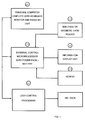
- figure 1 contains the block diagram of a possible configuration of a plant in accordance with the invention;
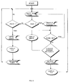
- figure 2 is a flow chart relating to the plant management system;
- figure 3 schematically illustrates a rack for the introduction and storage of skis;
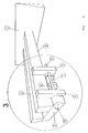
- figure 4 is a perspective view of a detail of the rack compartment locking and unlocking control devices;
- figure 5 is a side view of the devices shown in figure 3.
- In figure 3, no. 1 indicates the ski rack assembly consisting of a metal structure comprising a number of pairs of
arms 2, each of which, together with its support, constitutes a compartment for the introduction of one or more pairs of skis. - Each of these compartments has a locking device, a possible design of which is illustrated in figures 4 and 5.
- With reference to the latter figures, this closing device comprises a pair of
supports 4 welded toarms 2; the said supports are fitted with ashaft 5, to which acompartment closing arm 6 is hinged, and anelectromagnet 7 which acts on apin 8, pushed outwards by a spring 9 to insert it into anopening 10 inarm 6 when the latter is in the compartment locking position. - This position is shown in figures 4 and 5.
- Each
electromagnet 7 is controlled in a known way by the processor-driven logical control unit shown as no. 11 in figure 1; the said unit is connected to anexternal microprocessor 15, controlled in turn by amain computer 16, which manages the plant. The number of racks can be increased. In this case each rack, e.g. with 10 locks, is controlled by aprocessor 11 which locks and unlocks the compartments and is controlled byexternal logic unit 15; the latter is connected tomain computer 16, as shown in figure 1 which illustrates the units making up the system. -
Main computer 16 is connected via a serial port toexternal microprocessor 15. Viaexternal processor 15,main computer 16 controls the operation of the system in accordance with a program whose flow chart is summarised in figure 2.Computer 16 also collects operational data in a data base, such as frequency of use of the locks or the time the skis remain in the compartment. Both the data base and the management program can be devised in a known way by an expert in the field, and are therefore not illustrated here. - No. 15 indicates the external processor which collects the data received from bar-code or
magnetic card reader 12 and fromkeypad 13, and sends it to the serial port ofcomputer 16. It also carries out commands received frommain computer 16 by sending messages to display 14 and output commands to processor 11 (processor 11,keypad 13 anddisplay 14 are not illustrated in figure 3, which schematically shows a casing, indicated as no. 3, that contains them). - No. 11 indicates the lock control processor which carries out the locking and unlocking commands sent by
computer 16 viaprocessor 15. As mentioned, the number of racks can be increased, in which case a number of lock control processors will be connected viaprocessor 15 tomain computer 16. - The operation of the system will be understood by analysing figure 2, which contains the flow chart of the program run by
computer 16. - Via a command sent to processor 15 (wait for card), the computer activates the bar-code or magnetic card reader. The user who has just placed his skis in an unlocked compartment inserts his card for reading. If the card does not correspond to one associated with a locked compartment (ie. it is a new one), the keypad is enabled (enable keypad). The user enters the number of the compartment in which he has placed the skis, and if the number entered is correct (ie. is not a non-existent number and does not correspond to a compartment already occupied), the compartment is locked and the program started.
- The program goes back to the start, and places the bar-code or magnetic card reader on hold (wait for card). Users who have paid for the hire of the compartment insert their cards again when they are ready to collect their skis. This time the computer recognises that the card is not new, as it corresponds to a locked compartment. If the hire of the compartment has been paid for and the restaurant manager has confirmed payment by entering the customers compartment number at the time of payment, the computer orders the compartment to be unlocked, displays a confirmation message (display OK message), releases the card and returns to its initial status.
- It is also possible to include the
external processors main computer 16, even if this requires the use of a large number of cables to connect the racks with the computer. - As will be clear from the above description, the system in accordance with the invention on the one hand provides efficient ski storage as it is only possible to collect the skis by entering the code stored at the time of deposit, and on the other hand allows the plant manager to manage the ski racks with no need for specific personnel, as the equipment can be monitored via the main computer.
- The system in accordance with the invention could obviously be used in various fields, e.g. left-luggage offices, etc., and an expert in the field could devise numerous modifications and variations, all of which should be considered to fall within the scope of this invention.
- Thus, for example,
lock control processors 11 could be incorporated inexternal processor 15, orlock control processors 11 andexternal processor 15 could both be incorporated inmain computer 16, obviously with a sufficient number of cables to connectcomputer 16 to the locks.
Claims (5)
- Ski storage rack control system in which each rack consists of a set of compartments fitted with locks connected to a processor (16), characterised by the fact that it involves:• the input into and storage in the said computer of a code univocally associated with the user;• the association of the said code with the selected compartment number;• locking of the compartment;• re-input of the user code into the computer after the compartment unlocking enable has been given by the plant manager via computer (16);• comparison of this code with the code previously stored, following which unlocking of the compartment is enabled.
- Ski storage rack control system in accordance with claim 1, in which each rack consists of a set of compartments and a lock control processor (11) connected to an external control processor (15), which in turn is controlled by a main computer (16), characterised by the fact that it involves:• the input into and storage in the said external control computer (15) of a code univocally associated with the user;• the association of the said code with the selected compartment number;• locking of the compartment when the compartment number is entered by the user;• re-input of the user code into external control computer (15) after the compartment unlocking enable has been given by the plant manager via central control computer (16);• comparison of this code with the code previously stored, following which unlocking of the compartment is enabled.
- Ski rack storage control system in accordance with claim 2, in which the lock control processor is managed by the external processor (15), external processor (15) is managed by the main computer (16), and the code and compartment data are input by the user into external control computer (15).
- Equipment for the storage of objects, especially skis, of the type comprising a number of compartments in which the objects to be stored are inserted, characterised by the fact that it includes:• a rack lock control processor (11);• an external processor (15), which is controlled by a main computer (16) and controls the said processor (11);• systems for introducing and storing a user identification code in the said external computer (15);• systems for associating the said code with the compartment number;• systems for giving the compartment unlocking enable to the said external processor (15) via the said central unit;• systems for comparing a code input by the user at the time of collection with the code previously stored and, if the central unit enables compartment opening, unlocking the compartment.
- Ski storage equipment in accordance with claim 3, in which the said external processor (15) is connected to input devices designed to allow the input by the user of the code and compartment number.
Applications Claiming Priority (2)
| Application Number | Priority Date | Filing Date | Title |
|---|---|---|---|
| ITPC940023 | 1994-11-22 | ||
| IT94PC000023A IT1278267B1 (en) | 1994-11-22 | 1994-11-22 | SYSTEM FOR CONTROL OF DEVICES FOR THE STORAGE OF OBJECTS, IN PARTICULAR FOR THE CONTROL OF RACKS FOR THE STORAGE |
Publications (2)
| Publication Number | Publication Date |
|---|---|
| EP0714068A2 true EP0714068A2 (en) | 1996-05-29 |
| EP0714068A3 EP0714068A3 (en) | 1998-04-15 |
Family
ID=11389103
Family Applications (1)
| Application Number | Title | Priority Date | Filing Date |
|---|---|---|---|
| EP95118005A Withdrawn EP0714068A3 (en) | 1994-11-22 | 1995-11-15 | Control system for object storage devices, especially for ski racks and related equipment |
Country Status (2)
| Country | Link |
|---|---|
| EP (1) | EP0714068A3 (en) |
| IT (1) | IT1278267B1 (en) |
Cited By (3)
| Publication number | Priority date | Publication date | Assignee | Title |
|---|---|---|---|---|
| GB2472254A (en) * | 2009-07-31 | 2011-02-02 | David Young | Wirelessly operated lock for sports equipment |
| WO2011012887A1 (en) * | 2009-07-31 | 2011-02-03 | David Young | Ski, ski pole, and/or snowboard lock |
| AT526039A1 (en) * | 2022-03-30 | 2023-10-15 | Citybull Ges M B H | Sports equipment stand for theft-proof storage of sports equipment |
Citations (3)
| Publication number | Priority date | Publication date | Assignee | Title |
|---|---|---|---|---|
| US4774571A (en) * | 1987-05-20 | 1988-09-27 | Fariborz Mehdipour | Computerized ticket dispenser system |
| US5038023A (en) * | 1989-06-28 | 1991-08-06 | C. Itoh Information Systems Development, Inc. | System for storing and monitoring bar coded articles such as keys in a drawer |
| GB2273596A (en) * | 1992-12-16 | 1994-06-22 | Thor Engineering Limited | Vehicle authorisation system |
-
1994
- 1994-11-22 IT IT94PC000023A patent/IT1278267B1/en active IP Right Grant
-
1995
- 1995-11-15 EP EP95118005A patent/EP0714068A3/en not_active Withdrawn
Patent Citations (3)
| Publication number | Priority date | Publication date | Assignee | Title |
|---|---|---|---|---|
| US4774571A (en) * | 1987-05-20 | 1988-09-27 | Fariborz Mehdipour | Computerized ticket dispenser system |
| US5038023A (en) * | 1989-06-28 | 1991-08-06 | C. Itoh Information Systems Development, Inc. | System for storing and monitoring bar coded articles such as keys in a drawer |
| GB2273596A (en) * | 1992-12-16 | 1994-06-22 | Thor Engineering Limited | Vehicle authorisation system |
Cited By (4)
| Publication number | Priority date | Publication date | Assignee | Title |
|---|---|---|---|---|
| GB2472254A (en) * | 2009-07-31 | 2011-02-02 | David Young | Wirelessly operated lock for sports equipment |
| WO2011012887A1 (en) * | 2009-07-31 | 2011-02-03 | David Young | Ski, ski pole, and/or snowboard lock |
| AT526039A1 (en) * | 2022-03-30 | 2023-10-15 | Citybull Ges M B H | Sports equipment stand for theft-proof storage of sports equipment |
| EP4272848A1 (en) * | 2022-03-30 | 2023-11-08 | Citybull Ges.m.b.H. | Stand for sport devices |
Also Published As
| Publication number | Publication date |
|---|---|
| ITPC940023A0 (en) | 1994-11-22 |
| EP0714068A3 (en) | 1998-04-15 |
| ITPC940023A1 (en) | 1996-05-22 |
| IT1278267B1 (en) | 1997-11-17 |
Similar Documents
| Publication | Publication Date | Title |
|---|---|---|
| US5979753A (en) | Device and method for secure data updates in a self-checkout system | |
| US8990110B2 (en) | Autonomous operations of securable devices | |
| CA2010365C (en) | Storage system with adjacent lockers controlled by a microprocessor device | |
| US5987438A (en) | Electronic wallet system | |
| US4845484A (en) | Retrofit, newspaper tracking audit system for newspaper rack machines | |
| NZ257489A (en) | Local access control of gaming machines in casino by smart card key | |
| WO2001040907A2 (en) | A system, method, and computer program for managing storage and distribution of money tills | |
| EP0803846B1 (en) | Transaction-oriented electronic accommodation system | |
| JP2002304559A (en) | Electronic lock type coin locker, reserving system therefor and luggage transferring system using the same | |
| JP4273641B2 (en) | Charge settlement system | |
| JP2503192B2 (en) | Unmanned store equipment | |
| US20010013010A1 (en) | Electronic parking meter locking system | |
| EP0714068A2 (en) | Control system for object storage devices, especially for ski racks and related equipment | |
| EP0442349A1 (en) | Minibar system | |
| JPH09305808A (en) | Bicycle parking lot managing device | |
| EP0704826A2 (en) | Arrangement and method for utilizing a lockable space | |
| JP4870977B2 (en) | Facility management system using automatic settlement machine | |
| JP2518949B2 (en) | ID authentication processing system | |
| KR100283820B1 (en) | Integrated management system for ticket examination work | |
| EP1179813B1 (en) | Method and apparatus for performing value transactions | |
| JPH11102459A (en) | Security managing system for automatic transaction device | |
| JPH0142420B2 (en) | ||
| JPH05342226A (en) | Change reserve fund management system | |
| CN113112705A (en) | Lottery storage cabinet and lottery station | |
| JP2004054692A (en) | Locker system |
Legal Events
| Date | Code | Title | Description |
|---|---|---|---|
| PUAI | Public reference made under article 153(3) epc to a published international application that has entered the european phase |
Free format text: ORIGINAL CODE: 0009012 |
|
| AK | Designated contracting states |
Kind code of ref document: A2 Designated state(s): AT CH DE FR IT LI |
|
| PUAL | Search report despatched |
Free format text: ORIGINAL CODE: 0009013 |
|
| AK | Designated contracting states |
Kind code of ref document: A3 Designated state(s): AT CH DE FR IT LI |
|
| 17P | Request for examination filed |
Effective date: 19981013 |
|
| 17Q | First examination report despatched |
Effective date: 19990226 |
|
| STAA | Information on the status of an ep patent application or granted ep patent |
Free format text: STATUS: THE APPLICATION IS DEEMED TO BE WITHDRAWN |
|
| 18D | Application deemed to be withdrawn |
Effective date: 20000601 |