EP0714314B1 - Inhalator with breath flow regulation - Google Patents
Inhalator with breath flow regulation Download PDFInfo
- Publication number
- EP0714314B1 EP0714314B1 EP94924346A EP94924346A EP0714314B1 EP 0714314 B1 EP0714314 B1 EP 0714314B1 EP 94924346 A EP94924346 A EP 94924346A EP 94924346 A EP94924346 A EP 94924346A EP 0714314 B1 EP0714314 B1 EP 0714314B1
- Authority
- EP
- European Patent Office
- Prior art keywords
- pathway
- cross
- sectional area
- obstructing
- air
- Prior art date
- Legal status (The legal status is an assumption and is not a legal conclusion. Google has not performed a legal analysis and makes no representation as to the accuracy of the status listed.)
- Expired - Lifetime
Links
Images


Classifications
-
- G—PHYSICS
- G05—CONTROLLING; REGULATING
- G05D—SYSTEMS FOR CONTROLLING OR REGULATING NON-ELECTRIC VARIABLES
- G05D7/00—Control of flow
- G05D7/01—Control of flow without auxiliary power
- G05D7/0126—Control of flow without auxiliary power the sensing element being a piston or plunger associated with one or more springs
-
- A—HUMAN NECESSITIES
- A61—MEDICAL OR VETERINARY SCIENCE; HYGIENE
- A61M—DEVICES FOR INTRODUCING MEDIA INTO, OR ONTO, THE BODY; DEVICES FOR TRANSDUCING BODY MEDIA OR FOR TAKING MEDIA FROM THE BODY; DEVICES FOR PRODUCING OR ENDING SLEEP OR STUPOR
- A61M15/00—Inhalators
- A61M15/0001—Details of inhalators; Constructional features thereof
- A61M15/002—Details of inhalators; Constructional features thereof with air flow regulating means
-
- A—HUMAN NECESSITIES
- A61—MEDICAL OR VETERINARY SCIENCE; HYGIENE
- A61M—DEVICES FOR INTRODUCING MEDIA INTO, OR ONTO, THE BODY; DEVICES FOR TRANSDUCING BODY MEDIA OR FOR TAKING MEDIA FROM THE BODY; DEVICES FOR PRODUCING OR ENDING SLEEP OR STUPOR
- A61M15/00—Inhalators
- A61M15/0028—Inhalators using prepacked dosages, one for each application, e.g. capsules to be perforated or broken-up
-
- G—PHYSICS
- G05—CONTROLLING; REGULATING
- G05D—SYSTEMS FOR CONTROLLING OR REGULATING NON-ELECTRIC VARIABLES
- G05D7/00—Control of flow
- G05D7/01—Control of flow without auxiliary power
- G05D7/0106—Control of flow without auxiliary power the sensing element being a flexible member, e.g. bellows, diaphragm, capsule
- G05D7/0113—Control of flow without auxiliary power the sensing element being a flexible member, e.g. bellows, diaphragm, capsule the sensing element acting as a valve
-
- G—PHYSICS
- G05—CONTROLLING; REGULATING
- G05D—SYSTEMS FOR CONTROLLING OR REGULATING NON-ELECTRIC VARIABLES
- G05D7/00—Control of flow
- G05D7/01—Control of flow without auxiliary power
- G05D7/0126—Control of flow without auxiliary power the sensing element being a piston or plunger associated with one or more springs
- G05D7/0133—Control of flow without auxiliary power the sensing element being a piston or plunger associated with one or more springs within the flow-path
-
- G—PHYSICS
- G05—CONTROLLING; REGULATING
- G05D—SYSTEMS FOR CONTROLLING OR REGULATING NON-ELECTRIC VARIABLES
- G05D7/00—Control of flow
- G05D7/01—Control of flow without auxiliary power
- G05D7/0173—Control of flow without auxiliary power using pivoting sensing element acting as a valve mounted within the flow-path
-
- A—HUMAN NECESSITIES
- A61—MEDICAL OR VETERINARY SCIENCE; HYGIENE
- A61M—DEVICES FOR INTRODUCING MEDIA INTO, OR ONTO, THE BODY; DEVICES FOR TRANSDUCING BODY MEDIA OR FOR TAKING MEDIA FROM THE BODY; DEVICES FOR PRODUCING OR ENDING SLEEP OR STUPOR
- A61M2202/00—Special media to be introduced, removed or treated
- A61M2202/06—Solids
- A61M2202/064—Powder
Definitions
- This invention relates to an inhalation device incorporating novel means for regulating the rate of patient inspiration.
- Known inhalation devices suitable for the administration to the lung of any inhalation medicament include devices which administer the medicament in liquid form, in dry powder form or as a suspension of the solid medicament in a liquified propellant.
- Devices of the first mentioned type include nebuliser devices wherein a fine respirable mist is formed by action of a compressed gas on a sample, by vibration of a piezoelectric crystal or by other ultrasonic means; also, devices of the type described in e.g. International Patent Application WO 91/14468, where the liquid is sprayed through a small aperture.
- Devices of the second mentioned type which may provide the medicament in unit dose or multidose form include the well known SPINHALER (Registered Trademark), which is described in UK Patent 1122284, the TURBUHALER (Registered Trademark) which is described in United States Patent 4,524,769, and the device described in European Patent Application 407028.
- SPINHALER Registered Trademark
- TURBUHALER Registered Trademark
- Devices of the third mentioned type which generally contain a pressurised reservoir of liquified propellant containing a suspension of the solid medicament and a metering valve for dispensing a suitable dose, are also very well known in the art and is not necessary to describe any particular type here.
- this arrangement suffers from the disadvantage that whilst the velocity of air in the primary conduit may be reduced, a large volume of non drug-containing air is drawn in through the secondary air conduit, with the result that the breath of air necessary to secure a proper dose can become very long and drawn out. Furthermore, the arrangement may not be suitable for all the types of inhalation device described previously.
- GB-A-2104393 (Glaxo) relates to an inhalation device comprising a housing for medicaments in an aerosol container.
- the device includes a valve located in a passage between the housing and an outlet. In use, the valve closes if the rate of flow of air inhaled by a patient exceeds a pre-determined amount.
- this arrangement has no influence on the minimum flow rate through the device.
- obstructing means we mean any element made of a material which is wholly or partially impervious to air and which is suitable for restricting the flow of air through the pathway.
- the obstructing means may be manufactured from a metal, plastic, rubber or other suitably dense material and may be of entirely solid contruction, or it may be made partially permeable to air by the provision of channels.
- biassing means we mean any means for providing a restraint to movement against the bias on the application of pressure or suction which also provides a restoring force in the opposite direction on the release of pressure or suction.
- Suitable biassing means include springs, where the spring may be compressed or stretched, for example, coil, torsion or leaf springs; elastomeric materials which are reversibly deformable; and resilient curved materials (including those made of metal, rubber or plastic) where the curve may be reversibly straightened.
- the pressure fall at the mouthpiece may desirably be amplified by providing an air inlet which is constricted.
- the cross-sectional area of the air inlet is less than the maximum cross-sectional area of the pathway.
- the air inlet comprises one or more apertures that have a total cross-sectional area of less than 25%, especially 10%, more especially 5% of the maximum cross-sectional area of the pathway.
- the air flow regulating means described above are adapted to regulate the maximum and minimum velocity of airflow through the device.
- the second movable obstructing means is adapted to reduce the cross-sectional area of the pathway at a location between the first obstructing means and the means for dispensing medicament.
- the second biassing means comprises a spring biassed along the longitudinal axis of the device and the second obstructing means comprises a shutter mounted on the spring.
- first obstructing means and biassing means comprise the elements described above as (a) to (d).
- first obstructing means has the construction described in (c) above.
- cross-sectional area of the pathway when the second obstructing means is in the first position is substantially zero.
- the first and second obstructing means may be combined into a single element which may move between 3 positions.
- a device for the administration of an inhalation medicament including a body defining a through-going air pathway having a longitudinal axis, an air inlet, an air outlet forming a mouthpiece, means for dispensing medicament into the pathway and air flow regulating means, characterised in that the air flow regulating means includes a movable obstructing means adapted to reduce the cross-sectional area of the pathway at a location between the air inlet and the means for dispensing medicament, and biassing means, whereby the obstructing means is biassed into a first resting position in which the cross-sectional area of the pathway is minimum and is adapted to move against the bias of the biassing means to a second position in which the cross-sectional area of the pathway is maximum in response to a pressure fall at the mouthpiece caused by inhalation and is adapted to move further to a third position in which the cross-sectional area of the pathway is less than maximum in response to a greater pressure fall at
- the obstructing means is of substantially circular section along an axis perpendicular to the longitudinal axis of the pathway.
- the obstructing means is of substantially square or rectangular section along an axis perpendicular to the longitudinal axis of the pathway.
- cross-sectional area of the pathway when the obstructing means is in the first position is substantially zero.
- the device body defining the through going-pathway will be made of a rigid material, for example plastic or metal, and is preferably of substantially circular or square cross-section, although the shape of the section may at least in part be determined by the nature of the obstructing means.
- the inhalation device according to the invention is particularly suitable for desired air flows in the range 20-250 l/min, especially 30-120 l/min, particularly 40-80 l/min. Pressure reduction that may be created between the air inlet and the mouthpiece in a device according to the invention, will typically be in the range 0.1-20 mbar.
- the air flow regulating means may be provided as an integral part of the housing of the inhalation device or as a separately manufactured portion of the device which may be affixed to the remainder of the inhalation device by means of a weld, a male-female type connection, a screw-thread or a mechanical equivalent.
- the affixation may be permanent, or it may provide for the two portions to be attached and detached as desired, for example, to facilitate cleaning of the device.
- the air flow regulating means is adapted to be reversibly attached to and detached from the remainder of the device.
- Inhalation devices for use in accordance with the invention include any device conventionally used for dispensing powdered medicament for inhalation. Suitable devices include single dose dry powder inhalers e.g. the SPINHALER (Registered Trademark) inhaler and the DISKHALER (Registered Trademark) inhaler and multi-dose powder inhalers e.g. the TURBUHALER (Registered Trademark) inhaler and the device described in European Patent Application 407028.
- SPINHALER Registered Trademark
- DISKHALER Registered Trademark
- multi-dose powder inhalers e.g. the TURBUHALER (Registered Trademark) inhaler and the device described in European Patent Application 407028.
- the device is a device for the inhalation of a dry powdered medicament or a medicament in aqueous solution.
- the device is a device for the inhalation of a dry powdered medicament.
- Devices for inhalation of a medicament according to the invention are advantageous in that they are more effective or efficient, give a greater therapeutic benefit, are safer, are easier or cheaper to manufacture or assemble than those of the prior art. They are also advantageous in that, in use, the flow of air to the patient is more desirably or accurately controlled, the patient is able to obtain a larger or more consistent dose of medicament or they have other more desirable properties than known inhalation devices.
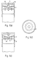
- Figure 1(a) shows a longitudinal section through an illustrative inhalation device similar to the SPINHALER (Registered Trademark) incorporating air flow regulating means, according to the second aspect of the invention, in the resting position.
- SPINHALER Registered Trademark
- Figure 1(b) shows a longitudinal section through the device of figure 1(a) with the air flow regulating means in the second position in which the cross-sectional area of the air pathway is maximum.
- Figure 1(c) shows a longitudinal section through the device of figure 1(b) with the air flow regulating means in a third position in which the cross-sectional area of the pathway is less than maximum.
- Figure 1(d) shows a cross-section along line I-I of Figure 1(a).
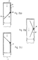
- Figure 2(a) shows a longitudinal section through a device according to the second aspect of the invention showing the air flow regulating means in the resting position.
- Figure 2(b) shows a longitudinal section through the device of figure 2(a) with the air flow regulating means in a second position in which the cross-sectional area of the air pathway is maximum.
- Figure 2(c) shows a longitudinal section through the device of figure 2(a) with the air flow regulating means in a third position in which the cross-sectional area of the pathway is less than maximum.
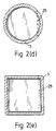
- Figure 2(d) shows a plan view of the device of figure 2(c) with the air-flow regulating means in the third position taken from the direction of arrow A and in which the cross-section is circular.
- Figure 2(e) is similar to Figure 2(d) save that the cross-section is square.
- Figure 3(a) shows a longitudinal section through a device according to the second aspect of the invention with the air flow regulating means in the resting position.
- Figure 3(b) shows a longitudinal section through the device of figure 3(a) with the air flow regulating means in a second position in which the cross-sectional area of the air pathway is maximum.
- Figure 3(c) shows a longitudinal section through the device of figure 3(a) with the air flow regulating means in a third position in which the cross-sectional area of the pathway is less than maximum.
- Figure 4(a) shows a longitudinal section through a device according to the second aspect of the invention with the air flow regulating means in the resting position.
- Figure 4(b) shows a longitudinal section through the device of figure 4(a) with the air flow regulating means in a second position in which the cross-sectional area of the air pathway is maximum.
- Figure 4(c) shows a longitudinal section through the device of figure 4(a) with the air flow regulating means in a third position in which the cross-sectional area of the pathway is less than maximum.
- Figure 5(a) shows a longitudinal section through a device according to the second aspect of the invention with the air flow regulating means in the resting position.
- Figure 5(b) shows a longitudinal section through the device of figure 5(a) with the air flow regulating in a second position in which the cross-sectional area of the air pathway is maximum.
- Figure 5(c) shows a longitudinal section through the device of figure 5(a) with the air flow regulating means in a third position in which the cross-sectional area of the pathway is less than maximum.
- Figure 6(a) shows a longitudinal section through a device according to the first aspect of the invention with an air flow regulating means having first and second obstructing means in the resting position.
- Figure 6(b) shows a longitudinal section through the device of figure 6(a) wherein the second obstructing means is in a second position in which the cross-sectional area of the air pathway is more than minimum.
- Figure 6(c) shows a longitudinal section through the device of figure 6(b) wherein the first obstructing means is in a second position in which the cross-sectional area of the pathway is less than maximum.
- Figure 7(a) shows a longitudinal section through a device outside the scope of the invention with the air flow regulating means in the resting position.
- Figure 7(b) shows a longitudinal section through the device of figure 7(a) with the air flow regulating means in a second position in which the cross-sectional area of the pathway is minimum.
- Figure 8 shows a longitudinal section through a device outside the scope of the invention with the air flow regulating means in the resting position.
- Figure 9(a) shows a longitudinal section through a device outside the scope of the invention with the air flow regulating means in the resting position.
- Figure 9(b) shows a longitudinal section through the device of figure 9(a) with the air flow regulating means between the first and second positions.
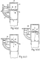
- Figure 10(a) shows a longitudinal section through a device outside the scope of the invention with the air flow regulating means in the resting position.
- Figure 10(b) shows a longitudinal section through the device of figure 10(a) with the air flow regulating means between the first and second positions.
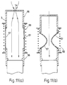
- Figure 11(a) shows a longitudinal section through a device outside the scope of the invention with the air flow regulating means in the resting position.
- Figure 11(b) shows a longitudinal section through the device of figure 11(a) with the air flow regulating means between the first and second positions.
- Figure 12(a) shows a longitudinal section through a device outside the scope of the invention with the air flow regulating means in the resting position.
- Figure 12(b) shows a longitudinal section through the device of figure 12(a) with the air flow regulating means between the first and second positions.
- Figure 13 shows the results of experimental tests performed on embodiments of the invention.
- a dry powder inhalation device comprises a generally cylindrical body defining a through-going pathway, said body comprising a mouth piece portion 1 , a closure portion 2 and an air-flow regulator portion 3 .
- Closure portion 2 is provided, at its end which connects with mouthpiece portion 1 , with a peripheral flange 4 within which the end of mouthpiece portion 1 fits closely.
- Air flow regulator portion 3 is provided, at its end which connects with closure portion 2 , with a peripheral flange 5 within which the end of closure portion 2 fits closely.
- mouthpiece portion 1 is tapered to form a frustoconical mouthpiece 6 .
- a simple bearing 7 is supported by cross members 8 .
- a spindle 9 is seated in bearing 7 .
- Spindle 9 is provided with a cup 10 which is capable of closely receiving a perforated capsule 11 containing medicament to be inhaled, which together form means for dispensing medicament.
- Spindle 9 is also provided with rotor vanes 12 which cause spindle 9 to rotate within bearing 7 when air is drawn through the device, as during inhalation.
- Closure portion 2 is provided, at its end remote from the mouthpiece portion 1 , with a perforated grid 13 .
- Air flow regulator portion 3 having an air inlet aperture 14 in first partition 15 is provided with a second partition 16 on the mouthpiece side of the first partition 15 in between which two partitions is located a perforated diaphragm 17 .
- Perforated diaphragm 17 is provided with a protrusion 18 on the inlet side which cooperates with and closes air inlet aperture 14 in first partition 15 in the resting position and a protrusion 19 on the outlet side which is adapted to cooperate with and close an aperture 20 in second partition 16 in response to a pressure drop at the mouthpiece caused by inhalation.
- Second partition 16 also contains further apertures 21 .
- Figure 1(d) shows a possible arrangement of perforations in diaphragm 17.
- perforated diaphragm 17 may be provided with any number of protrusions 18 to its surface on the air inlet side which cooperate with an equal number of apertures 14 in first partition 15 . In an alternative arrangement, there may exist an excess number of apertures 14 over the number of protrusions 18 . Equally, perforated diaphragm 17 may be provided with one or more protrusions 19 to its surface on the outlet side which cooperate with an equal number of apertures 20 in second partition 16 , or the number of apertures 20 in partition 16 may exceed the number of protrusions 19 on perforated diaphragm 17 .
- the air flow regulator portion 3 of the inhalation device comprises an air inlet 22 and contains a hinged V-shaped vane 27 having two portions 23 and 24 which is able to rotate about an axis perpendicular to the pathway at a hinge 25 (shown in figures 2(d) and 2(e)) against the bias of spring 26 .
- the cross-sectional area of the pathway is substantially zero.
- vane 27 rotates about its axis against the bias of spring 26 , thus increasing the cross-sectional area of the pathway and allowing the flow of air. At a point at which the vane has half rotated, the flow of air is maximum.
- the two portions 23 , 24 of vane 27 may be gas impermeable, in which case the flow of air at rest and at minimum pressure at the mouthpiece will be entirely prevented, or either or both portions may be perforated, in which case some flow of air will be allowed when the flow regulator portion 3 of the inhalation device is in the first or third positions.
- air flow regulator portion 3 of the inhalation device comprises an air inlet 22 and is provided with an annular flange 28 which retains a disc 29 having a central channel 30 and an outer groove 31 in which the flange 28 fits loosely.
- the groove 31 in disc 29 is biased against the air outlet side of flange 28 by means of spring 32 which is supported by a protrusion 33 on flange 28 .
- air flow regulator portion 3 of the inhalation device comprises an air inlet 22 and contains a partition 34 provided with a first aperture 35 .
- Aperture 35 is, in the resting position, closed by a shutter 36 provided with a second aperture 37 , which shutter is slidably engaged with the partition. Movement of the shutter 37 is controlled by a piston 38 retained in piston housing 39 which forms part of the housing of flow regulator portion 3 and which is biased against one or more springs 40 .
- the piston 38 is in gaseous communication with the air outlet at the mouthpiece (not shown) by means of a channel 41 connecting the piston housing 39 and a part of the air flow regulator portion 3 on the air outlet side of the shutter 36 .
- apertures 35 and 37 and the distance of travel of piston 38 may be such that the pathway is completely closed at rest when a pressure drop is produced at the mouthpiece, or that the cross-sectional area of the pathway under these conditions is small.
- air flow regulator portion 3 of the inhalation device comprises an air inlet 22 and is provided with a circumferential groove 42 which retains a disc 43 having a central channel 44 and an outer flange 45 around which the groove 42 fits loosely.
- the flange 45 on disc 43 is biased against the inlet side of groove 42 in the housing by means of spring 46 which is supported by a base 47 .
- Base 47 is illustrated as a grille; however it may alternatively consititute a protrusion into the pathway from the wall of the air flow regulator portion 3 at a point on the outlet side of the groove 42 , or a cross-piece, or it may constitute some other mechanical equivalent which will be apparent to a person skilled in the art.
- the air flow regulator portion 3 and disc 29 or 45 are of circular section. However, they may also be of another shaped section, for example, of rectangular or square section.
- disc 29 or 45 may have any number of channels which may be arranged as desired. Alternatively, although this is not preferred, they may be entirely solid in which case the minimum flow rate will be zero.
- air flow regulator portion 3 of the inhalation device having an air inlet aperture 14 in first partition 15 is provided with a second perforated partition 16 towards the outlet, in between which is located a shutter 48 which is urged against air inlet aperture 14 by the bias of spring 49 and a curved resilient flap 50 made of elastomeric material which rests against second partition 16 on the air inlet side of second partition 16 and in which the curvature of the flap 50 is directed towards the air inlet.
- air flow regulator portion 3 of the inhalation device having an air inlet 22 is provided with a grille or perforated partition 16 on the air inlet side of which rests a curved resilient flap 50 made of elastomeric material, the curvature of which flap is directed towards the air inlet.
- the operation of the device in response to a varying strength suction applied at the mouthpiece is essentially as described above for figures 6(b) and 6(c).
- the curved resilient flap 50 of figure 7 is replaced by a rotatable rigid flap 51 which is hinged at the wall of the housing of the air flow regulator portion 3 such that the axis of rotation is perpendicular to the direction of air flow.
- the rigid flap 51 is biassed towards the air inlet by spring 52 located at the hinge.
- spring 52 located at the hinge.
- rigid flap 51 is urged against perforated partition 16 thereby reducing the cross-sectional area of the air pathway and restricting the flow of air.
- the housing of the air flow regulator portion 3 of the inhalation device which we prefer to be of square section, and which is provided with an air inlet 2 2, contains two cooperating flaps 53 , 54 of resilient elastomeric material which are deflected towards the air inlet.
- flaps 53 , 54 are replaced by a larger number of flaps in a frusto-conical arrangement in which case the cross-section of the air flow regulator portion 3 is desirably circular.
- air flow regulator portion 3 of the inhalation device consists of two portions 55 and 56 , the former of which is provided with a constricted air inlet 14 , the two portions of the housing being connected by an annular segment of membrane made of thin elastomeric material 57 held rigid by the presence of two or more solid supports 58 .
- the elastomeric membrane is present not as an annular segment, but as two part semi-annular segments located diametrically opposite each other and in which the supports 58 are formed as an integral part of the housing tube.
- This variant on the tenth embodiment can be expected to operate in the same manner as the tenth embodiment, although it may have further advantages for example in ease of manufacture.
- air flow regulator portion 3 of the inhalation device is of circular section and consists of two portions 55 and 56 , the former of which is provided with a constricted air inlet 14 , the two portions of the housing being connected by an annular segment of membrane made of inelastic material 57 held rigid and extended by the presence of spring 59 .
- air flow regulator portion 3 of the inhalation device having constricted air inlet 14 contains along its length two partitions 60 retained in pockets 61 in the housing of the air flow regulator portion 3 , with which they form an airtight seal.
- Partitions 60 are adapted to slide along an axis perpendicular to the longitudinal axis of the device, and are in gaseous communication with the outside of the housing through airholes 62 .
- Springs 63 bias partitions 60 into their resting position within pockets 61 .
- perforated grid 13 may be omitted from the construction, particularly if the closure portion 2 and the air flow regulator portion 3 are moulded as one piece rather than two.
- Embodiments were tested experimentally to investigate their air flow characteristics as follows:
- An inhalation device was constructed which comprised a conventional SPINHALER (Registered Trademark) and an air flow regulator portion as illustrated in figure 6 in which the size of aperture 14 was 6.3 mm, the inside diameter of the housing of the air flow regulator portion was 20.7 mm, the elastomeric flap 50 was circular and manufactured of vulcanised rubber and the spring 49 consisted of a single turn of fine steel wire.
- SPINHALER Registered Trademark
- the device was tested using a vacuum generator to simulate patient inhalation.
- a maximum flow-rate was obtained at 41 l/min, which flow rate is known to be in the desirable range for efficient inhalation of dry-powdered medicament.
- FIG. 1 An air flow regulator portion for an inhalation device according to the invention was constructed as illustrated in figure 1 in which the inside diameter of the air flow regulating portion 3 was 50 mm, the diameter of the aperture 14 was 5 mm, diaphragm 17 was constructed of silicone rubber of thickness 0.95 mm and protrusions 18 and 19 were manufactured of a rigid plastics material (acetal). Protrusions 18 and 19 were affixed to the diaphragm by means of a screw fixture on protrusion 18 which passed through the diaphragm 17 into a threaded socket within protrusion 19 . An airtight cooperation between protrusion 18 and aperture 14 in the resting position was ensured by the provision of a 3 mm thick foam rubber surround to aperture 14 . Diaphragm 17 contained a single circular perforation of diameter 5 mm. Three tests were performed with other dimensions as follows:
- the S-shaped profiles of tests 2(a), 2(b) and 2(c) illustrate minimum and maximum flow control characteristics of the device according to the invention.
Abstract
Description
Protrusions 18 and 19 were affixed to the diaphragm by means of a screw fixture on
Three tests were performed with other dimensions as follows:
Claims (24)
- A device for the administration of an inhalation medicament, including a body defining a through-going air pathway having a longitudinal axis, an air inlet, (14), and air outlet forming a mouthpiece (1), means for dispensing medicament (11) into the pathway and air flow regulating means (3) which includes a movable obstructing means (50) adapted to reduce the cross- sectional area of the pathway at a location between the air inlet (14) and the means for dispensing medicament (11), and biassing means, whereby the obstructing means (50) is biassed into a first resting position in which the cross-sectional area of the pathway is maximum and is adapted to move against the bias of the biassing means to a second position in which the cross-sectional area of the pathway is less than maximum in response to a pressure fall at the mouthpiece (1) caused by inhalation, characterised in that the air flow regulating means (3) further includes second movable obstructing means (48) adapted to reduce the cross-sectional area of the pathway at a location between the air inlet (14) and the means for dispensing medicament (11), and second biassing means (49), whereby the second obstructing means (48) is biassed into a first resting position in which the cross-sectional area of the pathway is minimum and is adapted to move against the bias of the biassing means (49) to a second position in which the cross-sectional area of the pathway is more than minimum in response to a pressure fall at the mouthpiece caused by inhalation
- A device according to claim 1 wherein the cross-sectional area of the air inlet (14) is less than the maximum cross-sectional area of the pathway.
- A device according to claim 1 or claim 2 wherein the obstructing means (50) comprises one or more partitions adapted to slide across the pathway along an axis perpendicular to the longitudinal axis of the pathway thereby obstructing the pathway.
- A device according to claim 1 or claim 2 in which the obstructing means (50) comprises an annular segment of membrane (57) which connects two portions of the body (55,56).
- A device according to claim 4 in which the membrane (57) is made of elastomeric material, and the biassing means comprises the resistance of the elastomeric material to stretching in a direction perpendicular to the longitudinal axis of the pathway.
- A device according to claim 4 in which the obstructing means (50) comprises an annular segment of membrane (57) made of inelastic material and the biassing means provides a bias against movement of the two portions of the body towards each other along the longitudinal axis of the pathway.
- A device according to claim 1 or claim 2 in which the obstructing means comprises a rigid grille or perforated sheet (16) formed in a plane perpendicular to the longitudinal axis of the pathway on the air inlet side of which rests a flap (50) which in its resting position is deflected towards the air inlet (14) and in its second position is urged against the grille or perforated sheet (16).
- A device according to claim 7 in which the flap (51) is rigid and is hinged about an axis perpendicular to the longitudinal axis of the pathway and the biassing means comprises a spring (52) at the hinge of the flap (51).
- A device according to claim 7 in which the flap (50) is made of a resilient elastomeric material and the biassing means consists of curvature introduced into the flap (50) said curvature being directed towards the air inlet (14).
- A device according to claim 1 or claim 2 in which the obstructing and biassing means together comprise two or more cooperating flaps (53,54) of resilient elastomeric material which in the first position are deflected towards the air inlet (14) and which in the second position are urged together thus reducing the cross-sectional area of the pathway.
- A device according to any one of claims 1 to 10 wherein the second biassing means comprises a spring (49) biassed along the longitudinal axis of the device and wherein the second obstructing means comprises a shutter (48) mounted on the spring (49).
- A device according to any one of claims 1 or 11 in which the cross sectional area of the pathway when the second obstructing means (48) is in the first position, is substantially zero.
- A device for the administration of an inhalation medicament, including a body defining a through-going air pathway having a longitudinal axis, an air inlet (14), an air outlet forming a mouthpiece (1), means for dispensing medicament (11) into the pathway and air flow regulating means (3), characterised in that the air flow regulating means (3) includes a movable obstructing means (17) adapted to reduce the cross- sectional area of the pathway at a location between the air inlet (14) and the means for dispensing medicament (11), and biassing means, whereby the obstructing means (17) is biassed into a first resting position in which the cross-sectional area of the pathway is minimum and is adapted to move against the bias of the biassing means to a second position in which the cross-sectional area of the pathway is maximum in response to a pressure fall at the mouthpiece (1) caused by inhalation and is adapted to move further to a third position in which the cross-sectional area of the pathway is less than maximum in response to a greater pressure fall at the mouthpiece caused by inhalation.
- A device according to claim 13 in which the obstructing means is provided with an outer groove (31) and which is retained in the housing by means of a flange (28) within the housing around which it fits loosely.
- A device according to claim 13 in which the obstructing means is provided with an outer flange (29) and which is retained in the housing by means of a groove within the housing within which it fits loosely.
- A device according to claim 13 in which the biassing means and obstructing means together comprise a perforated diaphragm (17) made of resilient elastomeric material formed in a plane perpendicular to the longitudinal axis of the pathway.
- A device according to claim 16 in which the diaphragm (17) is provided with one or more protrusions (18,19) on its upper and lower surfaces and is located between two partitions (15,16) formed in a plane perpendicular to the longitudinal axis of the pathway, the partitions (15,16) being provided with apertures (14,20,21) with which some or all of the protrusions cooperate to restrict or prevent the passage of air through the apertures.
- A device according to any one of claims 13 to 17 in which the obstructing means (17) is of substantially circular section along an axis perpendicular to the longitudinal axis of the pathway.
- A device according to claim 13 in which the obstructing means comprises a V-shaped vane (27), biassed at a hinge (25) formed at the apex of the V, which rotates about an axis perpendicular to that of the pathway.
- A device according to claim 13 in which the pathway is divided by a partition (34) provided with first aperture (35) and the obstructing means comprises a shutter (36) provided with a second aperture (37) slidably engaged with the partition (34), which shutter (36) is made to slide against the partition (34) against the bias of the biassing means (40) by a piston (38) in gaseous communication with the mouthpiece (1).
- A device according to any one of claims 1, 2, 3, 6, 13, 14, 15, 19 and 20 in which the biassing means comprises a spring (32, 40, 46, 49).
- A device according to any one of claims 13 to 21 in which the cross-sectional area of the pathway when the obstructing means (17) is in the first position, is substantially zero.
- A device according to any one of claims 1 to 22 in which the air flow regulating means (3) is adapted to be reversibly attached to and detached from the remainder of the device.
- An air flow regulating means (3) as defined in any preceding claim, adapted for use in conjunction with a device for the administration of an inhalation medicament.
Applications Claiming Priority (7)
| Application Number | Priority Date | Filing Date | Title |
|---|---|---|---|
| GB9317197 | 1993-08-18 | ||
| GB9317196 | 1993-08-18 | ||
| GB939317197A GB9317197D0 (en) | 1993-08-18 | 1993-08-18 | Gas flow regulator |
| GB9317198 | 1993-08-18 | ||
| GB939317196A GB9317196D0 (en) | 1993-08-18 | 1993-08-18 | Gas flow regulator |
| GB939317198A GB9317198D0 (en) | 1993-08-18 | 1993-08-18 | Gas flow regulator |
| PCT/GB1994/001812 WO1995005208A1 (en) | 1993-08-18 | 1994-08-18 | Inhalator with breath flow regulation |
Publications (2)
| Publication Number | Publication Date |
|---|---|
| EP0714314A1 EP0714314A1 (en) | 1996-06-05 |
| EP0714314B1 true EP0714314B1 (en) | 1998-10-14 |
Family
ID=27266819
Family Applications (1)
| Application Number | Title | Priority Date | Filing Date |
|---|---|---|---|
| EP94924346A Expired - Lifetime EP0714314B1 (en) | 1993-08-18 | 1994-08-18 | Inhalator with breath flow regulation |
Country Status (12)
| Country | Link |
|---|---|
| US (2) | US5727546A (en) |
| EP (1) | EP0714314B1 (en) |
| JP (1) | JP3545764B2 (en) |
| AT (1) | ATE172124T1 (en) |
| CA (1) | CA2169760C (en) |
| DE (1) | DE69413989T2 (en) |
| DK (1) | DK0714314T3 (en) |
| ES (1) | ES2122319T3 (en) |
| FI (1) | FI114448B (en) |
| NO (1) | NO312436B1 (en) |
| SG (1) | SG82544A1 (en) |
| WO (1) | WO1995005208A1 (en) |
Cited By (2)
| Publication number | Priority date | Publication date | Assignee | Title |
|---|---|---|---|---|
| US6606992B1 (en) | 1999-06-30 | 2003-08-19 | Nektar Therapeutics | Systems and methods for aerosolizing pharmaceutical formulations |
| US8408200B2 (en) | 1998-10-09 | 2013-04-02 | Novartis Ag | Flow resistance modulated aerosolized active agent delivery |
Families Citing this family (161)
| Publication number | Priority date | Publication date | Assignee | Title |
|---|---|---|---|---|
| JP3317823B2 (en) * | 1995-08-11 | 2002-08-26 | 株式会社ユニシアジェックス | Dosing device |
| JP3328132B2 (en) * | 1996-03-21 | 2002-09-24 | 株式会社ユニシアジェックス | Inhaler type dispenser |
| GB2312848B (en) * | 1996-04-26 | 1999-11-17 | Bespak Plc | Controlled flow inhalers |
| JPH1189935A (en) * | 1997-09-24 | 1999-04-06 | Unisia Jecs Corp | Inhalation type dosing apparatus |
| US20060165606A1 (en) | 1997-09-29 | 2006-07-27 | Nektar Therapeutics | Pulmonary delivery particles comprising water insoluble or crystalline active agents |
| CA2228182C (en) * | 1998-01-26 | 2007-03-20 | George Volgyesi | Breath-powered mist inhaler |
| JP3488620B2 (en) * | 1998-02-05 | 2004-01-19 | 株式会社日立ユニシアオートモティブ | Inhalation type dispenser |
| AP1342A (en) * | 1998-03-16 | 2004-12-15 | Nektar Therapeutics | Aerosolized active agent delivery. |
| AU2006201914B2 (en) * | 1998-03-16 | 2008-07-24 | Novartis Ag | Aerosolized active agent delivery |
| SE9801114D0 (en) * | 1998-03-30 | 1998-03-30 | Astra Ab | Inhalation device |
| GB2344535B (en) * | 1998-12-11 | 2000-10-18 | Bespak Plc | Inhalation apparatus |
| FR2787031B1 (en) * | 1998-12-11 | 2001-03-30 | Valois Sa | IMPROVED INHALATION DEVICE |
| DE19912461B4 (en) * | 1999-03-19 | 2006-07-20 | GSF - Forschungszentrum für Umwelt und Gesundheit GmbH | Device for limiting the flow at low differential pressures |
| US9006175B2 (en) | 1999-06-29 | 2015-04-14 | Mannkind Corporation | Potentiation of glucose elimination |
| US7305986B1 (en) | 1999-07-23 | 2007-12-11 | Mannkind Corporation | Unit dose capsules for use in a dry powder inhaler |
| WO2001007107A2 (en) * | 1999-07-23 | 2001-02-01 | Pharmaceutical Discovery Corporation | Unit dose capsules and dry powder inhaler |
| US7464706B2 (en) | 1999-07-23 | 2008-12-16 | Mannkind Corporation | Unit dose cartridge and dry powder inhaler |
| US6427688B1 (en) | 2000-02-01 | 2002-08-06 | Dura Pharmaceuticals, Icn. | Dry powder inhaler |
| US20030003057A1 (en) * | 2000-07-07 | 2003-01-02 | Jeffry Weers | Methods for administering leuprolide by inhalation |
| AU6124601A (en) * | 2000-05-10 | 2001-11-20 | Alliance Pharmaceutical Corporation | Phospholipid-based powders for drug delivery |
| US7871598B1 (en) | 2000-05-10 | 2011-01-18 | Novartis Ag | Stable metal ion-lipid powdered pharmaceutical compositions for drug delivery and methods of use |
| US8404217B2 (en) | 2000-05-10 | 2013-03-26 | Novartis Ag | Formulation for pulmonary administration of antifungal agents, and associated methods of manufacture and use |
| US6453900B1 (en) * | 2000-06-09 | 2002-09-24 | Pulmonary Services, Inc. | Inhaler device |
| US6553988B1 (en) * | 2000-06-09 | 2003-04-29 | Norton Healthcare, Inc. | Medicament dispensing device with a multimaterial diaphragm bounding a pneumatic force chamber |
| WO2001095786A2 (en) | 2000-06-16 | 2001-12-20 | Rajiv Doshi | Methods and devices for improving breathing in patients with pulmonary disease |
| GB2364919A (en) * | 2000-07-21 | 2002-02-13 | Cambridge Consultants | Inhalers |
| AU2001283546A1 (en) | 2000-08-14 | 2002-02-25 | Advanced Inhalation Research, Inc. | Inhalation device and method |
| US6792947B1 (en) * | 2000-08-25 | 2004-09-21 | O-Two Systems International Inc. | Flow control valve for manual resuscitator devices |
| SE517226C2 (en) * | 2000-09-25 | 2002-05-14 | Microdrug Ag | Inhaler with air brake for dry powder |
| FI20002363A0 (en) * | 2000-10-27 | 2000-10-27 | Orion Yhtymae Oyj | powder inhaler |
| EP2301616B8 (en) * | 2000-12-22 | 2019-07-24 | ResMed Pty Ltd | Flow regulation vent |
| US7073499B1 (en) | 2001-02-06 | 2006-07-11 | Injet Digital Aerosols Limited | Inhaler with airflow regulation |
| ZA200306564B (en) * | 2001-02-26 | 2004-10-15 | Optinose As | Nasal devices. |
| US6766799B2 (en) | 2001-04-16 | 2004-07-27 | Advanced Inhalation Research, Inc. | Inhalation device |
| DE10126807C2 (en) * | 2001-06-01 | 2003-12-04 | Pari Gmbh | Inhalation therapy device with a valve to limit the flow of inspiration |
| US6550493B2 (en) * | 2001-06-13 | 2003-04-22 | Baxter International Inc. | Vacuum demand valve |
| EP1399210B1 (en) * | 2001-06-20 | 2013-08-21 | Novartis AG | Aerosolization device |
| FI20011317A0 (en) * | 2001-06-20 | 2001-06-20 | Orion Corp | The powder inhaler |
| JP3619176B2 (en) * | 2001-09-14 | 2005-02-09 | オムロンヘルスケア株式会社 | Aerosol particle sorting device and inhaler |
| WO2003041777A1 (en) * | 2001-11-14 | 2003-05-22 | Nektar Therapeutics | Aerosolization device with improved endpiece connection |
| JP4437040B2 (en) * | 2001-11-14 | 2010-03-24 | ネクター セラピューティクス | Aerosolization device with connectable body and end piece |
| US20030168057A1 (en) * | 2001-12-14 | 2003-09-11 | Inhale Therapeutic Systems, Inc. | Electronically controllable aerosol delivery |
| JP2005514393A (en) | 2001-12-19 | 2005-05-19 | ネクター セラピューティクス | Supplying aminoglycosides to the lung |
| US6705316B2 (en) | 2002-03-11 | 2004-03-16 | Battelle Pulmonary Therapeutics, Inc. | Pulmonary dosing system and method |
| ES2300568T3 (en) | 2002-03-20 | 2008-06-16 | Mannkind Corporation | INHALATION APPARATUS |
| US6985798B2 (en) | 2002-05-10 | 2006-01-10 | Oriel Therapeutics, Inc. | Dry powder dose filling systems and related methods |
| US6889690B2 (en) * | 2002-05-10 | 2005-05-10 | Oriel Therapeutics, Inc. | Dry powder inhalers, related blister devices, and associated methods of dispensing dry powder substances and fabricating blister packages |
| US7118010B2 (en) | 2002-05-10 | 2006-10-10 | Oriel Therapeutics, Inc. | Apparatus, systems and related methods for dispensing and /or evaluating dry powders |
| US7677411B2 (en) * | 2002-05-10 | 2010-03-16 | Oriel Therapeutics, Inc. | Apparatus, systems and related methods for processing, dispensing and/or evaluatingl dry powders |
| US7185651B2 (en) * | 2002-06-18 | 2007-03-06 | Nektar Therapeutics | Flow regulator for aerosol drug delivery and methods |
| WO2004002395A2 (en) * | 2002-06-27 | 2004-01-08 | Oriel Therapeutics, Inc. | Apparatus, systems and related methods for processing, dispensing and/or evaluating non-pharmaceutical dry powders |
| US6887220B2 (en) * | 2002-09-12 | 2005-05-03 | Gore Enterprise Holdings, Inc. | Catheter having a compliant member configured to regulate aspiration rates |
| GB0227128D0 (en) * | 2002-11-20 | 2002-12-24 | Glaxo Group Ltd | A capsule |
| AU2003293361A1 (en) * | 2002-12-18 | 2004-07-29 | Glaxo Group Limited | Drug delivery system with vented mouthpiece |
| CA2520265C (en) * | 2003-04-09 | 2015-02-17 | Nektar Therapeutics | Aerosolization apparatus with capsule puncture alignment guide |
| GB0308969D0 (en) | 2003-04-17 | 2003-05-28 | Glaxo Group Ltd | Capsules |
| EP1670531A4 (en) * | 2003-09-16 | 2009-02-18 | Injet Digital Aerosols Ltd | Inhaler with air flow regulation |
| US7377277B2 (en) * | 2003-10-27 | 2008-05-27 | Oriel Therapeutics, Inc. | Blister packages with frames and associated methods of fabricating dry powder drug containment systems |
| US7451761B2 (en) * | 2003-10-27 | 2008-11-18 | Oriel Therapeutics, Inc. | Dry powder inhalers, related blister package indexing and opening mechanisms, and associated methods of dispensing dry powder substances |
| GB0325628D0 (en) * | 2003-11-03 | 2003-12-10 | Glaxo Group Ltd | A hand=-held capsule device |
| CA2554136C (en) * | 2004-02-24 | 2013-05-28 | Microdose Technologies, Inc. | Synthetic jet based medicament delivery method and apparatus |
| MX2007001903A (en) | 2004-08-20 | 2007-08-02 | Mannkind Corp | Catalysis of diketopiperazine synthesis. |
| KR101306384B1 (en) | 2004-08-23 | 2013-09-09 | 맨카인드 코포레이션 | Diketopiperazine salts, diketomorpholine salts or diketodioxane salts for drug delivery |
| US10610228B2 (en) | 2004-12-08 | 2020-04-07 | Theravent, Inc. | Passive nasal peep devices |
| US9833354B2 (en) | 2004-12-08 | 2017-12-05 | Theravent, Inc. | Nasal respiratory devices |
| US7806120B2 (en) * | 2004-12-08 | 2010-10-05 | Ventus Medical, Inc. | Nasal respiratory devices for positive end-expiratory pressure |
| CN101166555B (en) * | 2004-12-08 | 2010-05-12 | 温吐斯医学公司 | Respiratory devices and methods of use |
| ATE373498T1 (en) * | 2005-07-06 | 2007-10-15 | Activaero Gmbh | ADJUSTABLE VALVE AND INHALATION DEVICE |
| US20080251072A1 (en) * | 2005-07-13 | 2008-10-16 | Amar Lulla | Inhaler Device |
| JP5465878B2 (en) | 2005-09-14 | 2014-04-09 | マンカインド コーポレイション | Method of drug formulation based on increasing the affinity of crystalline microparticle surfaces for active agents |
| CN104383546B (en) | 2006-02-22 | 2021-03-02 | 曼金德公司 | Method for improving the pharmaceutical properties of microparticles comprising diketopiperazines and an active agent |
| EP2026723B1 (en) * | 2006-05-23 | 2018-11-21 | Theravent, Inc. | Nasal respiratory devices |
| AU2007258524B2 (en) * | 2006-06-07 | 2012-05-03 | Ventus Medical, Inc. | Layered nasal devices |
| US20110203598A1 (en) * | 2006-06-07 | 2011-08-25 | Favet Michael L | Nasal devices including layered nasal devices and delayed resistance adapters for use with nasal devices |
| CA2658095A1 (en) * | 2006-08-01 | 2008-02-07 | Aradigm Corporation | Fluid flow regulating device |
| US8573197B2 (en) | 2006-10-25 | 2013-11-05 | Novartis Ag | Powder dispersion apparatus, method of making and using the apparatus, and components that can be used on the apparatus and other devices |
| WO2008061250A2 (en) * | 2006-11-16 | 2008-05-22 | Ventus Medical, Inc. | Adjustable nasal devices |
| WO2008091355A2 (en) * | 2007-01-24 | 2008-07-31 | Breathe Pharmaceuticals, Inc. | Drug transfer device |
| WO2008101991A1 (en) * | 2007-02-21 | 2008-08-28 | Novo Nordisk A/S | Breath actuation mechanism for an aerosol generating device |
| US8196576B2 (en) * | 2007-02-28 | 2012-06-12 | Microdose Therapeutx, Inc. | Inhaler |
| TW200836781A (en) * | 2007-03-07 | 2008-09-16 | Ventus Medical Inc | Nasal devices |
| US8528544B2 (en) * | 2007-05-30 | 2013-09-10 | Canon Kabushiki Kaisha | Inhaler |
| US8496002B2 (en) * | 2007-06-12 | 2013-07-30 | Civitas Therapeutics, Inc. | Powder inhaler devices |
| US20090064996A1 (en) * | 2007-09-10 | 2009-03-12 | Rosh Melvin S | Duo chamber |
| US8020700B2 (en) | 2007-12-05 | 2011-09-20 | Ventus Medical, Inc. | Packaging and dispensing nasal devices |
| CA2713514A1 (en) * | 2008-02-01 | 2009-08-13 | Ventus Medical, Inc. | Cpap interface and backup devices |
| GB0802028D0 (en) * | 2008-02-05 | 2008-03-12 | Dunne Stephen T | Powder inhaler flow regulator |
| WO2009117012A1 (en) | 2008-03-17 | 2009-09-24 | Ventus Medical, Inc. | Adhesive nasal respiratory devices |
| CA2719205C (en) * | 2008-03-27 | 2017-04-25 | Mannkind Corporation | A dry powder inhalation system |
| US8539951B1 (en) | 2008-05-27 | 2013-09-24 | Trudell Medical International | Oscillating positive respiratory pressure device |
| US8485180B2 (en) | 2008-06-13 | 2013-07-16 | Mannkind Corporation | Dry powder drug delivery system |
| CN104689432B (en) | 2008-06-13 | 2018-07-06 | 曼金德公司 | Diskus and the system for drug conveying |
| US20090308398A1 (en) * | 2008-06-16 | 2009-12-17 | Arthur Ferdinand | Adjustable resistance nasal devices |
| JP5479465B2 (en) | 2008-06-20 | 2014-04-23 | マンカインド コーポレイション | Interactive device and method for profiling inhalation efforts in real time |
| TWI494123B (en) | 2008-08-11 | 2015-08-01 | Mannkind Corp | Use of ultrarapid acting insulin |
| US20110218451A1 (en) * | 2008-09-15 | 2011-09-08 | Danny Yu-Youh Lai | Nasal devices, systems and methods |
| US8517010B2 (en) * | 2008-09-26 | 2013-08-27 | Stamford Devices Limited | Nebuliser system |
| US8327849B2 (en) | 2008-10-28 | 2012-12-11 | Trudell Medical International | Oscillating positive expiratory pressure device |
| US8314106B2 (en) | 2008-12-29 | 2012-11-20 | Mannkind Corporation | Substituted diketopiperazine analogs for use as drug delivery agents |
| US8408242B2 (en) * | 2009-02-04 | 2013-04-02 | Edward S Chang | Overflow shutoff valve |
| US9149589B2 (en) | 2009-02-23 | 2015-10-06 | Trudell Medical International | Method and device for performing orientation dependent oscillating positive expiratory pressure therapy |
| US8485179B1 (en) | 2009-02-23 | 2013-07-16 | Trudell Medical International | Oscillating positive expiratory pressure device |
| PL2405963T3 (en) | 2009-03-11 | 2014-04-30 | Mannkind Corp | Apparatus, system and method for measuring resistance of an inhaler |
| US8985101B2 (en) | 2009-05-21 | 2015-03-24 | Microdose Therapeutx, Inc. | Method and device for clamping a blister within a dry powder inhaler |
| MY159925A (en) * | 2009-05-21 | 2017-02-15 | Microdose Therapeutx Inc | Rotary cassette system for dry powder inhaler |
| EP2440184B1 (en) | 2009-06-12 | 2023-04-05 | MannKind Corporation | Diketopiperazine microparticles with defined specific surface areas |
| US9180263B2 (en) * | 2009-07-01 | 2015-11-10 | Microdose Therapeutx, Inc. | Laboratory animal pulmonary dosing device |
| US20110000481A1 (en) * | 2009-07-01 | 2011-01-06 | Anand Gumaste | Nebulizer for infants and respiratory compromised patients |
| EP2283887B1 (en) * | 2009-08-06 | 2012-07-04 | Activaero GmbH | Device for flow restriction at low differential pressures |
| WO2011056889A1 (en) | 2009-11-03 | 2011-05-12 | Mannkind Corporation | An apparatus and method for simulating inhalation efforts |
| US20110108041A1 (en) * | 2009-11-06 | 2011-05-12 | Elliot Sather | Nasal devices having a safe failure mode and remotely activatable |
| CN102686261B (en) | 2009-12-23 | 2014-09-10 | Map药物公司 | Enhanced eductor design |
| WO2011080761A1 (en) * | 2009-12-30 | 2011-07-07 | Thirumalai Anadampillai Aparna | An improved dry powder inhaler |
| WO2011085022A1 (en) * | 2010-01-05 | 2011-07-14 | Microdose Therapeutx, Inc. | Inhalation device and method |
| US8875711B2 (en) | 2010-05-27 | 2014-11-04 | Theravent, Inc. | Layered nasal respiratory devices |
| JP5543850B2 (en) * | 2010-06-15 | 2014-07-09 | 独立行政法人物質・材料研究機構 | Powdered drug inhalation device |
| RU2571331C1 (en) | 2010-06-21 | 2015-12-20 | Маннкайнд Корпорейшн | Systems and methods for dry powder drug delivery |
| DK2694402T3 (en) | 2011-04-01 | 2017-07-03 | Mannkind Corp | BLISTER PACKAGE FOR PHARMACEUTICAL CYLINDER AMPULS |
| CA3010658C (en) | 2011-06-06 | 2020-12-01 | Trudell Medical International | Oscillating positive expiratory pressure device |
| WO2012174472A1 (en) | 2011-06-17 | 2012-12-20 | Mannkind Corporation | High capacity diketopiperazine microparticles |
| AU2012328885B2 (en) | 2011-10-24 | 2017-08-31 | Mannkind Corporation | Methods and compositions for treating pain |
| AU2013289957B2 (en) | 2012-07-12 | 2017-02-23 | Mannkind Corporation | Dry powder drug delivery systems and methods |
| WO2014066856A1 (en) | 2012-10-26 | 2014-05-01 | Mannkind Corporation | Inhalable influenza vaccine compositions and methods |
| US9517315B2 (en) | 2012-11-30 | 2016-12-13 | Trudell Medical International | Oscillating positive expiratory pressure device |
| US11000714B2 (en) * | 2013-03-01 | 2021-05-11 | Draeger Safety Uk Limited | Breathing apparatus equipment |
| EP3587404B1 (en) | 2013-03-15 | 2022-07-13 | MannKind Corporation | Microcrystalline diketopiperazine compositions, methods for preparation and use thereof |
| BR112016000937A8 (en) | 2013-07-18 | 2021-06-22 | Mannkind Corp | dry powder pharmaceutical formulations, method for making a dry powder formulation and use of a dry powder pharmaceutical formulation |
| JP2016530930A (en) | 2013-08-05 | 2016-10-06 | マンカインド コーポレイション | Ventilation device and method |
| US9849257B2 (en) | 2013-08-22 | 2017-12-26 | Trudell Medical International | Oscillating positive respiratory pressure device |
| AU2015208121A1 (en) * | 2014-01-24 | 2016-07-21 | Aerocrine Ab | Miniaturized fluid flow regulating device |
| US10363383B2 (en) | 2014-02-07 | 2019-07-30 | Trudell Medical International | Pressure indicator for an oscillating positive expiratory pressure device |
| US10857315B2 (en) | 2014-02-21 | 2020-12-08 | David Brown | Inhalation device and method for inhaling powders |
| WO2015148905A1 (en) | 2014-03-28 | 2015-10-01 | Mannkind Corporation | Use of ultrarapid acting insulin |
| US10471222B2 (en) | 2014-07-01 | 2019-11-12 | Dance Biopharm Inc. | Aerosolization system with flow restrictor and feedback device |
| US10857313B2 (en) | 2014-07-01 | 2020-12-08 | Aerami Therapeutics, Inc. | Liquid nebulization systems and methods |
| US11273271B2 (en) | 2014-07-01 | 2022-03-15 | Aerami Therapeutics, Inc. | Aerosolization system with flow restrictor and feedback device |
| US20160033051A1 (en) * | 2014-07-31 | 2016-02-04 | Parker-Hannifin Corporation | Shutoff valve assembly |
| US10561806B2 (en) | 2014-10-02 | 2020-02-18 | Mannkind Corporation | Mouthpiece cover for an inhaler |
| MX2018001321A (en) | 2015-07-30 | 2018-08-15 | Trudell Medical Int | Combined respiratory muscle training and oscillating positive expiratory pressure device. |
| GB2542376A (en) * | 2015-09-16 | 2017-03-22 | Nicoventures Holdings Ltd | Aerosol provision system with variable airflow |
| EP3383465B1 (en) | 2015-12-04 | 2021-02-03 | Trudell Medical International | Huff cough simulation device |
| US20190001085A1 (en) * | 2015-12-21 | 2019-01-03 | 3M Innovative Properties Company | Medicinal inhalers |
| JP2019500196A (en) * | 2015-12-21 | 2019-01-10 | スリーエム イノベイティブ プロパティズ カンパニー | Flow regulator for use with medical inhalers |
| JP2019503829A (en) * | 2015-12-21 | 2019-02-14 | スリーエム イノベイティブ プロパティズ カンパニー | Flow regulator assembly for use in a medical inhaler |
| US10512921B2 (en) * | 2016-05-09 | 2019-12-24 | Funai Electric Co., Ltd. | Maintenance apparatus for vaporizing device |
| CA3225148A1 (en) | 2016-05-19 | 2017-11-23 | Mannkind Corporation | Apparatus, system and method for detecting and monitoring inhalations |
| WO2018071435A1 (en) | 2016-10-11 | 2018-04-19 | Microdose Therapeutx, Inc. | Inhaler and methods of use thereof |
| MX2019005888A (en) * | 2016-11-30 | 2019-08-14 | Philip Morris Products Sa | Inhaler with sized cavity. |
| CN109922852B (en) * | 2016-11-30 | 2023-11-07 | 菲利普莫里斯生产公司 | Inhaler with vortex end plugs |
| US10813881B2 (en) * | 2017-04-28 | 2020-10-27 | Otitopic Inc. | Dry powder inhalation device |
| EP3618908A4 (en) | 2017-05-03 | 2021-01-13 | Trudell Medical International | Combined oscillating positive expiratory pressure therapy and huff cough simulation device |
| WO2019002480A1 (en) * | 2017-06-29 | 2019-01-03 | Plastic Omnium Advanced Innovation And Research | A ventilation flow rate regulator for a pressurized vehicle tank |
| US10953278B2 (en) | 2018-02-02 | 2021-03-23 | Trudell Medical International | Oscillating positive expiratory pressure device |
| JP7360392B2 (en) * | 2018-03-26 | 2023-10-12 | フィリップ・モーリス・プロダクツ・ソシエテ・アノニム | Inhaler with vortex capsule cavity |
| AU2019276585A1 (en) * | 2018-06-01 | 2021-01-21 | Safebvm Corp. | Pressure safety device for bag valve mask |
| CN110833415A (en) * | 2018-08-15 | 2020-02-25 | 深圳市美好创亿医疗科技有限公司 | Expiratory NO detection system |
| US11793951B2 (en) | 2019-06-24 | 2023-10-24 | De Motu Cordis Pty Ltd | Automatic dispenser for respiratory delivery device and method |
| US11717621B2 (en) | 2019-06-24 | 2023-08-08 | De Motu Cordis Pty Ltd | Automatic dispenser for respiratory delivery device |
| US10828432B1 (en) * | 2019-06-24 | 2020-11-10 | De Motu Cordis Pty Ltd | Respiratory delivery device and method |
| CN113357216B (en) * | 2021-07-08 | 2022-11-15 | 哈尔滨碧研科技有限公司 | Gas circuit integrated device and valve block system |
| WO2023001685A1 (en) * | 2021-07-21 | 2023-01-26 | Jt International Sa | Vapour generating device |
Family Cites Families (29)
| Publication number | Priority date | Publication date | Assignee | Title |
|---|---|---|---|---|
| GB610309A (en) * | 1943-07-05 | 1948-10-14 | Dole Valve Co | Improvements in or relating to fluid control devices and method of controlling the flow of fluid |
| GB643262A (en) * | 1944-07-17 | 1950-09-15 | Dole Valve Co | Improvements in or relating to fluid control devices |
| IL26014A (en) * | 1965-06-28 | 1971-03-24 | Fahre O | Automatic regulating valve for ventilation plants |
| US3669113A (en) * | 1966-03-07 | 1972-06-13 | Fisons Ltd | Inhalation device |
| DE1566631B1 (en) * | 1968-05-23 | 1970-05-27 | Draegerwerk Ag | Surface evaporator for use in anesthetic circuit systems |
| GB1308322A (en) * | 1970-01-01 | 1973-02-21 | Barber Colman Co | Constant mass flow control device |
| US3837362A (en) * | 1972-05-23 | 1974-09-24 | Eaton Corp | Fluid flow control |
| US3874378A (en) * | 1973-09-06 | 1975-04-01 | Globe Safety Products Inc | Combined resuscitator and inhalator apparatus |
| GB1487676A (en) * | 1974-09-23 | 1977-10-05 | Christianson R | Demand regulator for a breathing apparatus |
| US3970105A (en) * | 1975-06-16 | 1976-07-20 | Continental Can Company, Inc. | Toroidal pressure regulator |
| US4092999A (en) * | 1977-04-25 | 1978-06-06 | Dana Corporation | Fluid control valve |
| CA1120372A (en) * | 1978-02-13 | 1982-03-23 | Max Isaacson | Demand inhalation valve system |
| US4259951A (en) * | 1979-07-30 | 1981-04-07 | Chesebrough-Pond's Inc. | Dual valve for respiratory device |
| GB2104393B (en) * | 1981-08-13 | 1984-11-07 | Glaxo Group Ltd | Medical inhalation devices |
| US7025784B1 (en) * | 1981-10-29 | 2006-04-11 | Hansa Medical Products, Inc. | Method and apparatus for a tracheal valve |
| FR2517209A1 (en) * | 1981-12-01 | 1983-06-03 | Intertechnique Sa | Respiratory regulator annular injector - has membrane and core giving rapid increase in pressure difference with flow rate |
| US4535767A (en) * | 1982-10-01 | 1985-08-20 | Tiep Brian L | Oxygen delivery apparatus |
| FR2519254B1 (en) * | 1982-11-26 | 1988-05-06 | Cuvier Claude | MODULATED DUAL CURRENT AIR CIRCULATION DEVICE IN PULMONARY WAVES |
| ES539092A0 (en) * | 1983-12-28 | 1985-11-01 | Coxwold Pty Ltd | A VALVE SET |
| US4534343A (en) * | 1984-01-27 | 1985-08-13 | Trutek Research, Inc. | Metered dose inhaler |
| GB2169810B (en) * | 1985-01-11 | 1988-05-25 | Coal Ind | Simulator |
| EP0198708B1 (en) * | 1985-04-15 | 1991-06-12 | Nippon Tansan Gas Co., Ltd. | Portable oxygen inhaler |
| DE3636669C2 (en) * | 1986-10-28 | 2001-08-16 | Siemens Ag | Arrangement for delivering aerosol to a patient's airways and / or lungs |
| US5309904A (en) * | 1991-01-28 | 1994-05-10 | Beck Blaine E | Insufflating/suctioning valve |
| US5161524A (en) * | 1991-08-02 | 1992-11-10 | Glaxo Inc. | Dosage inhalator with air flow velocity regulating means |
| CH685475A5 (en) * | 1992-04-10 | 1995-07-31 | Varioraw Percutive Sa | specific therapeutic device in the respiratory field. |
| US5437271A (en) * | 1993-04-06 | 1995-08-01 | Minnesota Mining And Manufacturing Company | Deagglomerators for dry powder inhalers |
| DE9321308U1 (en) * | 1993-05-28 | 1997-02-13 | Ritzau Pari Werk Gmbh Paul | Mouthpiece for inhalation therapy devices |
| US5349947A (en) * | 1993-07-15 | 1994-09-27 | Newhouse Michael T | Dry powder inhaler and process that explosively discharges a dose of powder and gas from a soft plastic pillow |
-
1994
- 1994-08-18 JP JP50684295A patent/JP3545764B2/en not_active Expired - Fee Related
- 1994-08-18 ES ES94924346T patent/ES2122319T3/en not_active Expired - Lifetime
- 1994-08-18 CA CA002169760A patent/CA2169760C/en not_active Expired - Fee Related
- 1994-08-18 DK DK94924346T patent/DK0714314T3/en active
- 1994-08-18 SG SG9607254A patent/SG82544A1/en unknown
- 1994-08-18 AT AT94924346T patent/ATE172124T1/en active
- 1994-08-18 US US08/596,311 patent/US5727546A/en not_active Expired - Lifetime
- 1994-08-18 WO PCT/GB1994/001812 patent/WO1995005208A1/en active IP Right Grant
- 1994-08-18 EP EP94924346A patent/EP0714314B1/en not_active Expired - Lifetime
- 1994-08-18 DE DE69413989T patent/DE69413989T2/en not_active Expired - Lifetime
-
1996
- 1996-02-15 NO NO19960610A patent/NO312436B1/en not_active IP Right Cessation
- 1996-02-16 FI FI960704A patent/FI114448B/en not_active IP Right Cessation
-
1998
- 1998-01-14 US US09/006,725 patent/US6109261A/en not_active Expired - Lifetime
Cited By (2)
| Publication number | Priority date | Publication date | Assignee | Title |
|---|---|---|---|---|
| US8408200B2 (en) | 1998-10-09 | 2013-04-02 | Novartis Ag | Flow resistance modulated aerosolized active agent delivery |
| US6606992B1 (en) | 1999-06-30 | 2003-08-19 | Nektar Therapeutics | Systems and methods for aerosolizing pharmaceutical formulations |
Also Published As
| Publication number | Publication date |
|---|---|
| JP3545764B2 (en) | 2004-07-21 |
| JPH09501581A (en) | 1997-02-18 |
| US5727546A (en) | 1998-03-17 |
| FI114448B (en) | 2004-10-29 |
| EP0714314A1 (en) | 1996-06-05 |
| FI960704A (en) | 1996-02-16 |
| CA2169760A1 (en) | 1995-02-23 |
| DE69413989T2 (en) | 1999-04-08 |
| WO1995005208A1 (en) | 1995-02-23 |
| DK0714314T3 (en) | 1999-06-23 |
| US6109261A (en) | 2000-08-29 |
| FI960704A0 (en) | 1996-02-16 |
| ATE172124T1 (en) | 1998-10-15 |
| NO960610L (en) | 1996-03-28 |
| NO960610D0 (en) | 1996-02-15 |
| SG82544A1 (en) | 2001-08-21 |
| CA2169760C (en) | 2006-06-06 |
| NO312436B1 (en) | 2002-05-13 |
| DE69413989D1 (en) | 1998-11-19 |
| ES2122319T3 (en) | 1998-12-16 |
Similar Documents
| Publication | Publication Date | Title |
|---|---|---|
| EP0714314B1 (en) | Inhalator with breath flow regulation | |
| US5983893A (en) | Inhalation device | |
| JP5069653B2 (en) | Respiratory drug delivery device | |
| EP0692990B1 (en) | Deagglomerators for dry powder inhalers | |
| US6889687B1 (en) | Inhalator with aerosolizing unit | |
| JP3825051B2 (en) | Inhaler | |
| US9757528B2 (en) | Nebulizer having different negative pressure threshold settings | |
| US4298023A (en) | Spring loaded exhalation valve | |
| US5727542A (en) | General purpose aerosol inhalation apparatus | |
| US6443151B1 (en) | Fluid velocity-sensitive trigger mechanism | |
| PT99710B (en) | MEDICATION DISTRIBUTION DEVICE | |
| US8684002B2 (en) | Device for flow rate limitation at low differential pressures | |
| EP1225942B1 (en) | Inhalator with aerosolizing unit | |
| WO2016108129A1 (en) | Pneumatically sealed exhalation valve | |
| EP2129421B8 (en) | Improved metered dose inhaler for aerosol | |
| RU2088264C1 (en) | Medication dosing apparatus | |
| US576041A (en) | Inhaler | |
| KR102600652B1 (en) | Device for inhalation | |
| WO2002011894A1 (en) | Diaphragm | |
| MXPA97004489A (en) | Inhalation device, method for dispersing a pharmaceutically active substance and method for administering a dose of a pharmaceutically acting substance | |
| CA2404344A1 (en) | Aerosol enhancement |
Legal Events
| Date | Code | Title | Description |
|---|---|---|---|
| PUAI | Public reference made under article 153(3) epc to a published international application that has entered the european phase |
Free format text: ORIGINAL CODE: 0009012 |
|
| 17P | Request for examination filed |
Effective date: 19960216 |
|
| AK | Designated contracting states |
Kind code of ref document: A1 Designated state(s): AT BE CH DE DK ES FR GB GR IE IT LI LU MC NL PT SE |
|
| 17Q | First examination report despatched |
Effective date: 19960605 |
|
| RAP1 | Party data changed (applicant data changed or rights of an application transferred) |
Owner name: FISONS PLC |
|
| GRAG | Despatch of communication of intention to grant |
Free format text: ORIGINAL CODE: EPIDOS AGRA |
|
| GRAG | Despatch of communication of intention to grant |
Free format text: ORIGINAL CODE: EPIDOS AGRA |
|
| GRAH | Despatch of communication of intention to grant a patent |
Free format text: ORIGINAL CODE: EPIDOS IGRA |
|
| GRAH | Despatch of communication of intention to grant a patent |
Free format text: ORIGINAL CODE: EPIDOS IGRA |
|
| GRAA | (expected) grant |
Free format text: ORIGINAL CODE: 0009210 |
|
| AK | Designated contracting states |
Kind code of ref document: B1 Designated state(s): AT BE CH DE DK ES FR GB GR IE IT LI LU MC NL PT SE |
|
| REF | Corresponds to: |
Ref document number: 172124 Country of ref document: AT Date of ref document: 19981015 Kind code of ref document: T |
|
| REG | Reference to a national code |
Ref country code: CH Ref legal event code: EP |
|
| REG | Reference to a national code |
Ref country code: CH Ref legal event code: NV Representative=s name: KIRKER & CIE SA |
|
| REF | Corresponds to: |
Ref document number: 69413989 Country of ref document: DE Date of ref document: 19981119 |
|
| ET | Fr: translation filed | ||
| REG | Reference to a national code |
Ref country code: ES Ref legal event code: FG2A Ref document number: 2122319 Country of ref document: ES Kind code of ref document: T3 |
|
| REG | Reference to a national code |
Ref country code: IE Ref legal event code: FG4D |
|
| REG | Reference to a national code |
Ref country code: PT Ref legal event code: SC4A Free format text: AVAILABILITY OF NATIONAL TRANSLATION Effective date: 19981117 |
|
| REG | Reference to a national code |
Ref country code: DK Ref legal event code: T3 |
|
| PLBE | No opposition filed within time limit |
Free format text: ORIGINAL CODE: 0009261 |
|
| STAA | Information on the status of an ep patent application or granted ep patent |
Free format text: STATUS: NO OPPOSITION FILED WITHIN TIME LIMIT |
|
| 26N | No opposition filed | ||
| PG25 | Lapsed in a contracting state [announced via postgrant information from national office to epo] |
Ref country code: MC Free format text: LAPSE BECAUSE OF NON-PAYMENT OF DUE FEES Effective date: 20000229 |
|
| REG | Reference to a national code |
Ref country code: GB Ref legal event code: IF02 |
|
| PGFP | Annual fee paid to national office [announced via postgrant information from national office to epo] |
Ref country code: LU Payment date: 20110825 Year of fee payment: 18 |
|
| PGFP | Annual fee paid to national office [announced via postgrant information from national office to epo] |
Ref country code: IE Payment date: 20110810 Year of fee payment: 18 Ref country code: DK Payment date: 20110810 Year of fee payment: 18 Ref country code: CH Payment date: 20110812 Year of fee payment: 18 |
|
| PGFP | Annual fee paid to national office [announced via postgrant information from national office to epo] |
Ref country code: SE Payment date: 20110811 Year of fee payment: 18 Ref country code: GR Payment date: 20110718 Year of fee payment: 18 Ref country code: GB Payment date: 20110817 Year of fee payment: 18 Ref country code: AT Payment date: 20110726 Year of fee payment: 18 Ref country code: DE Payment date: 20110810 Year of fee payment: 18 Ref country code: FR Payment date: 20110818 Year of fee payment: 18 Ref country code: ES Payment date: 20110915 Year of fee payment: 18 |
|
| PGFP | Annual fee paid to national office [announced via postgrant information from national office to epo] |
Ref country code: IT Payment date: 20110812 Year of fee payment: 18 Ref country code: NL Payment date: 20110818 Year of fee payment: 18 Ref country code: BE Payment date: 20110812 Year of fee payment: 18 |
|
| PGFP | Annual fee paid to national office [announced via postgrant information from national office to epo] |
Ref country code: PT Payment date: 20120220 Year of fee payment: 19 |
|
| BERE | Be: lapsed |
Owner name: *FISONS P.L.C. Effective date: 20120831 |
|
| REG | Reference to a national code |
Ref country code: NL Ref legal event code: V1 Effective date: 20130301 |
|
| REG | Reference to a national code |
Ref country code: CH Ref legal event code: PL |
|
| REG | Reference to a national code |
Ref country code: SE Ref legal event code: EUG Ref country code: DK Ref legal event code: EBP |
|
| REG | Reference to a national code |
Ref country code: AT Ref legal event code: MM01 Ref document number: 172124 Country of ref document: AT Kind code of ref document: T Effective date: 20120818 |
|
| GBPC | Gb: european patent ceased through non-payment of renewal fee |
Effective date: 20120818 |
|
| PG25 | Lapsed in a contracting state [announced via postgrant information from national office to epo] |
Ref country code: CH Free format text: LAPSE BECAUSE OF NON-PAYMENT OF DUE FEES Effective date: 20120831 Ref country code: NL Free format text: LAPSE BECAUSE OF NON-PAYMENT OF DUE FEES Effective date: 20130301 Ref country code: LI Free format text: LAPSE BECAUSE OF NON-PAYMENT OF DUE FEES Effective date: 20120831 Ref country code: SE Free format text: LAPSE BECAUSE OF NON-PAYMENT OF DUE FEES Effective date: 20120819 |
|
| REG | Reference to a national code |
Ref country code: GR Ref legal event code: ML Ref document number: 990400015 Country of ref document: GR Effective date: 20130304 |
|
| REG | Reference to a national code |
Ref country code: FR Ref legal event code: ST Effective date: 20130430 |
|
| REG | Reference to a national code |
Ref country code: IE Ref legal event code: MM4A |
|
| PG25 | Lapsed in a contracting state [announced via postgrant information from national office to epo] |
Ref country code: BE Free format text: LAPSE BECAUSE OF NON-PAYMENT OF DUE FEES Effective date: 20120831 Ref country code: GR Free format text: LAPSE BECAUSE OF NON-PAYMENT OF DUE FEES Effective date: 20130304 Ref country code: IT Free format text: LAPSE BECAUSE OF NON-PAYMENT OF DUE FEES Effective date: 20120818 |
|
| PG25 | Lapsed in a contracting state [announced via postgrant information from national office to epo] |
Ref country code: AT Free format text: LAPSE BECAUSE OF NON-PAYMENT OF DUE FEES Effective date: 20120818 |
|
| PG25 | Lapsed in a contracting state [announced via postgrant information from national office to epo] |
Ref country code: DK Free format text: LAPSE BECAUSE OF NON-PAYMENT OF DUE FEES Effective date: 20120831 Ref country code: GB Free format text: LAPSE BECAUSE OF NON-PAYMENT OF DUE FEES Effective date: 20120818 Ref country code: DE Free format text: LAPSE BECAUSE OF NON-PAYMENT OF DUE FEES Effective date: 20130301 Ref country code: IE Free format text: LAPSE BECAUSE OF NON-PAYMENT OF DUE FEES Effective date: 20120818 |
|
| PG25 | Lapsed in a contracting state [announced via postgrant information from national office to epo] |
Ref country code: FR Free format text: LAPSE BECAUSE OF NON-PAYMENT OF DUE FEES Effective date: 20120831 |
|
| REG | Reference to a national code |
Ref country code: DE Ref legal event code: R119 Ref document number: 69413989 Country of ref document: DE Effective date: 20130301 |
|
| REG | Reference to a national code |
Ref country code: ES Ref legal event code: FD2A Effective date: 20131021 |
|
| PG25 | Lapsed in a contracting state [announced via postgrant information from national office to epo] |
Ref country code: ES Free format text: LAPSE BECAUSE OF NON-PAYMENT OF DUE FEES Effective date: 20120819 |
|
| REG | Reference to a national code |
Ref country code: PT Ref legal event code: MM4A Free format text: LAPSE DUE TO NON-PAYMENT OF FEES Effective date: 20140218 |
|
| PG25 | Lapsed in a contracting state [announced via postgrant information from national office to epo] |
Ref country code: LU Free format text: LAPSE BECAUSE OF NON-PAYMENT OF DUE FEES Effective date: 20120818 |
|
| PG25 | Lapsed in a contracting state [announced via postgrant information from national office to epo] |
Ref country code: PT Free format text: LAPSE BECAUSE OF NON-PAYMENT OF DUE FEES Effective date: 20140218 |
|
| REG | Reference to a national code |
Ref country code: PT Ref legal event code: MM4A Free format text: MAXIMUM VALIDITY LIMIT REACHED Effective date: 20140818 |
|
| PG25 | Lapsed in a contracting state [announced via postgrant information from national office to epo] |
Ref country code: PT Free format text: LAPSE BECAUSE OF EXPIRATION OF PROTECTION Effective date: 20140826 |
|
| PG25 | Lapsed in a contracting state [announced via postgrant information from national office to epo] |
Ref country code: PT Free format text: LAPSE BECAUSE OF EXPIRATION OF PROTECTION Effective date: 20140225 |