EP0714635A1 - High frequency device for thermotherapic interstitial treatment of tumors - Google Patents
High frequency device for thermotherapic interstitial treatment of tumors Download PDFInfo
- Publication number
- EP0714635A1 EP0714635A1 EP95118244A EP95118244A EP0714635A1 EP 0714635 A1 EP0714635 A1 EP 0714635A1 EP 95118244 A EP95118244 A EP 95118244A EP 95118244 A EP95118244 A EP 95118244A EP 0714635 A1 EP0714635 A1 EP 0714635A1
- Authority
- EP
- European Patent Office
- Prior art keywords
- tube
- electrode
- cannula
- frequency
- rinsing
- Prior art date
- Legal status (The legal status is an assumption and is not a legal conclusion. Google has not performed a legal analysis and makes no representation as to the accuracy of the status listed.)
- Granted
Links
Images
Classifications
-
- A—HUMAN NECESSITIES
- A61—MEDICAL OR VETERINARY SCIENCE; HYGIENE
- A61B—DIAGNOSIS; SURGERY; IDENTIFICATION
- A61B18/00—Surgical instruments, devices or methods for transferring non-mechanical forms of energy to or from the body
- A61B18/04—Surgical instruments, devices or methods for transferring non-mechanical forms of energy to or from the body by heating
- A61B18/12—Surgical instruments, devices or methods for transferring non-mechanical forms of energy to or from the body by heating by passing a current through the tissue to be heated, e.g. high-frequency current
- A61B18/14—Probes or electrodes therefor
- A61B18/1482—Probes or electrodes therefor having a long rigid shaft for accessing the inner body transcutaneously in minimal invasive surgery, e.g. laparoscopy
-
- A—HUMAN NECESSITIES
- A61—MEDICAL OR VETERINARY SCIENCE; HYGIENE
- A61B—DIAGNOSIS; SURGERY; IDENTIFICATION
- A61B18/00—Surgical instruments, devices or methods for transferring non-mechanical forms of energy to or from the body
- A61B18/04—Surgical instruments, devices or methods for transferring non-mechanical forms of energy to or from the body by heating
- A61B18/12—Surgical instruments, devices or methods for transferring non-mechanical forms of energy to or from the body by heating by passing a current through the tissue to be heated, e.g. high-frequency current
- A61B18/14—Probes or electrodes therefor
- A61B18/1477—Needle-like probes
-
- A—HUMAN NECESSITIES
- A61—MEDICAL OR VETERINARY SCIENCE; HYGIENE
- A61B—DIAGNOSIS; SURGERY; IDENTIFICATION
- A61B18/00—Surgical instruments, devices or methods for transferring non-mechanical forms of energy to or from the body
- A61B2018/00053—Mechanical features of the instrument of device
- A61B2018/00107—Coatings on the energy applicator
Definitions
- the invention relates to a high-frequency therapy device according to the preamble of patent claim 1.
- High-frequency surgical coagulation and / or cutting devices with rinsing solution supply tubes or hoses are known in various designs (US-A-5122138, DE 39 21 000 A1, DE-U-87 07 820).
- the subject of the invention is an interstitial high-frequency therapy device in the frequency range from 300 kHz to 1 MHz with the supply of liquid to the treatment area.
- the object of the invention is not only to ensure uniform application of heat to the biological tissue around the tip of the work in the interstitium, but also to enable the device to be as minimally invasive as possible through the healthy tissue through to the target area (tumor, hyperplasia) and to adhere and dry out Avoid organic tissue at the work tip.
- rinsing solution outlet openings By providing a metal tip and rinsing solution outlet openings arranged behind it, when the working electrode is exposed to radio frequency after the working tip has been inserted into tissue, it is ensured that rinsing with a rinsing solution directly around the metal tip prevents organic tissue from adhering to the electrode and thermal drying out.
- the rinsing solution can also contribute to better heat distribution and heat transfer to the biological tissue if it is electrically conductive.
- inventions according to claims 2 to 4 are particularly advantageous because the cascade of rinsing solution outlet openings in the inner tube and the axial slots in the electrode tube creates a liquid cavern, which in conjunction with a teflon-coated shaft for particularly good axial sliding of the instrument in the bio-tissue and to one leads to optimal heat transfer.
- a high-frequency generator according to claim 9 is particularly suitable for the device according to the invention.
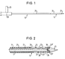
- the working electrode 13 of a high-frequency therapy device is cannula-like according to FIGS. 1 and 2 and, according to FIG. 1, has a rinsing liquid connection 28 and a laterally branching high-voltage connection 29 at its proximal end, which is connected to a high-frequency generator in a manner not shown, and in an electrically conductive working tip 15 on the distal end region.
- the rinsing channel or liquid channel 17 formed in the interior of the tube 21 is connected via the rinsing liquid connection 28 and a hose line, not shown, for example is attached to an infusion pump.
- the tube 21 has rinsing solution outlet openings 22 on the side, which openings are designed as radial micro bores. 3, several such micro bores 22 are distributed over the length and the circumference of the tube 21.
- the distal end region of the tube 21 is surrounded by an electrode tube 24 which is concentric with the tube 21 and which is flush with the tube 21 at the distal end completes.
- an electrode tube 24 which is concentric with the tube 21 and which is flush with the tube 21 at the distal end completes.
- the electrode tube 21 and preferably also the metal tip 23 consist of rustproof, electrically conductive and biocompatible material, preferably CrNi steels or NiTi alloys being used.
- an insulating tube 25 Connected at the rear to the electrode tube 24 is an insulating tube 25 which has the same diameter and the same wall thickness and is shrunk onto the tube 21 and which extends as far as FIG. 1 to the connecting piece 28, 29.
- the electrode tube 24 has axial slots 26, which each communicate with one of the micro bores 22.
- the micro bores 22 and the axial slots 26 form a passage for rinsing liquid with a flow rate of 50 to 100 ml / h, which is fed through the rinsing channel 17 with an internal diameter of about 0.6 to 0.7 mm from an infusion pump, not shown.
- the axial slots 26 distributed over the circumference and the length in the electrode tube 24 serve as rinsing liquid reservoirs (water caverns) which, after being inserted into the biological tissue, guarantee an unimpeded flow of rinsing liquid in the puncture channel around the cylinder jacket of the electrode tube 24, i.e. around the working tip 15, and adhere and Prevent drying out during thermal interactions with the bio-tissue or coagulate.
- the electrolytic conductivity in the target area for RF currents is achieved over long RF application times.
- the insulating tube 25 is preferably a tissue-compatible Teflon tube that is thermostable for steam sterilization up to 134 ° C. and has good non-stick and sliding properties.
- the outer diameter of the insulating tube 25 and the outer electrode tube 24 are the same size.
- the inner lumen 17 of the cannula-like tube 21 can be used for temperature control by means of a microthermocouple 30, which according to FIG Metal tip 23 is arranged at the distal end of the irrigation channel 17.
- a measuring line 31, indicated by dashed lines, runs from the microthermocouple 30 through the flushing channel 17 into the connecting piece 28, which is provided with a Y adapter, and from there in a manner not shown to a control unit, where the temperature evaluation takes place.
- Encapsulated microchips or NiCr-Ni-clad thermocouples with a diameter of 0.25 mm and with small thermal time constants of approximately 7 to 10 ms are suitable as microthermocouple 30.
- the method of operation of the high-frequency therapy device described is as follows: After the patient has been contacted with a neutral electrode and the HF needle applicator according to the invention has been introduced into the target area, the treatment process begins with a delay of about 15 s. After switching on the infusion pump and the high-frequency generator, the treatment site around the metal tip 23 with, for example Flushed with a 0.9% NaCl solution rinsing liquid and thus made electrically conductive in a targeted manner throughout. The thermal effects can also be achieved with non-electrolytic rinsing solutions, since the pathogenic biological tissue and the blood are electrolytically conductive. At the same time, a high-frequency current flows from the metal tip 23 (FIGS.
- the microthermocouple 30 (FIG. 2) heats up accordingly and emits a corresponding signal via the measuring line 31 to the control unit, which maintains the high-frequency generator at a predetermined temperature on the microthermocouple 30 Target performance can adjust.
- a certain operating time of the high-frequency generator can be set on a timer, not shown.
- the high-frequency generator preferably operates in intervals so that the temperature sensor signals can be evaluated without interference in the interval breaks.
- the working electrode 13 preferably consists of a cannula-shaped tube 21 with thin-walled and temperature-stable insulation 25, preferably 200 mm in length and 1.1 mm in outside diameter.
- the electrode tube 24 should have a length of 10, 20 or 30 mm and is available as an applicator set.
- the metal tip 23 with a tip angle of approximately 15 degrees or an oblique cut is connected to the tubes 21, 24 preferably by welding, in particular laser welding. It ensures low-force tissue displacement in the puncture channel and avoids clogging of the inner metal cannula 21.
- the flushing channel 17 of the tube 21 has a diameter of approximately 0.6 to 0.7 mm, the microthermocouple 30 has a diameter of 0.25 mm and a low thermal time constant of 7 to 10 ms.
- the temperature is advantageously recorded in the pauses of the high-frequency energy application, which is preferably carried out at intervals. Costly optical fiber temperature sensors and evaluation devices can thus be dispensed with.
- a real-time control of the spatial heat spread or the complete tumor denaturation during high-frequency thermotherapy is possible with known procedures of magnetic resonance tomography, since the longitudinal one Change relaxation times T1 of the hydrogen protons in a temperature-specific manner.
- the patient is part of an electrical high-frequency circuit with frequencies from 300 kHz to 1 MHz, the pathological tissue being contacted by the cannula-like tube 22 that supplies permanent rinsing liquid, the electrode tube 24 or the metal tip 23 in the interstitium.
- the rinsing solution and the pathological tissue in the applicator environment are slowly warmed up by the effects of current heat lasting a few minutes.
- the tissue is devitalized by coagulation.
- the high-frequency needle applicator according to the invention is suitable for known stereotaxy devices, biopsy devices or target devices in connection with imaging diagnostic devices (CT, ultrasound, X-ray) by suitable geometric modification.
- CT imaging diagnostic devices
- X-ray X-ray
Landscapes
- Health & Medical Sciences (AREA)
- Surgery (AREA)
- Engineering & Computer Science (AREA)
- Life Sciences & Earth Sciences (AREA)
- Biomedical Technology (AREA)
- Molecular Biology (AREA)
- Nuclear Medicine, Radiotherapy & Molecular Imaging (AREA)
- Plasma & Fusion (AREA)
- Physics & Mathematics (AREA)
- Heart & Thoracic Surgery (AREA)
- Medical Informatics (AREA)
- Otolaryngology (AREA)
- Animal Behavior & Ethology (AREA)
- General Health & Medical Sciences (AREA)
- Public Health (AREA)
- Veterinary Medicine (AREA)
- Surgical Instruments (AREA)
- Electrotherapy Devices (AREA)
Abstract
Description
Die Erfindung betrifft eine Hochfrequenz-Therapieeinrichtung nach dem Oberbegriff des Patentanspruchs 1.The invention relates to a high-frequency therapy device according to the preamble of patent claim 1.
Hochfrequenzchirurgische Koagulations- und/oder Schneidvorrichtungen mit Spüllösungszufuhrrohren bzw. -schläuchen sind in verschiedenen Ausführungen bekannt (US-A-5122138, DE 39 21 000 A1, DE-U-87 07 820).High-frequency surgical coagulation and / or cutting devices with rinsing solution supply tubes or hoses are known in various designs (US-A-5122138, DE 39 21 000 A1, DE-U-87 07 820).
Es ist auch schon bekannt (DE AS 1 007 960), an einem mit Hochfrequenz beschickten Elektrodenkopf seitlich Spüllösungsaustrittsöffnungen vorzusehen, um bei der Koagulation austretendes Blut fortzuspülen und damit klare Sicht durch die Optik eines Endoskops zu gewährleisten.It is also known (DE AS 1 007 960) to provide rinsing solution outlet openings on the side of an electrode head charged with high frequency, in order to flush away blood escaping during the coagulation and thus to ensure a clear view through the optics of an endoscope.
Die Erfindung hat eine interstitielle Hochfrequenz-Therapieeinrichtung im Frequenzbereich von 300 kHz bis 1MHz mit Flüssigkeitszufuhr zum Behandlungsgebiet zum Gegenstand. Die Aufgabe der Erfindung besteht darin, nicht nur eine gleichmäßige Wärmebeaufschlagung des Biogewebes um die Arbeitsspitze herum im Interstitium zu gewährleisten, sondern auch ein möglichst minimalinvasives Einstechen der Einrichtung durch gesundes Gewebe hindurch zum Zielgebiet (Tumor, Hyperplasie) zu ermöglichen und ein Anhaften sowie Austrocknen von Biogewebe an der Arbeitsspitze zu vermeiden.The subject of the invention is an interstitial high-frequency therapy device in the frequency range from 300 kHz to 1 MHz with the supply of liquid to the treatment area. The object of the invention is not only to ensure uniform application of heat to the biological tissue around the tip of the work in the interstitium, but also to enable the device to be as minimally invasive as possible through the healthy tissue through to the target area (tumor, hyperplasia) and to adhere and dry out Avoid organic tissue at the work tip.
Zur Lösung dieser Aufgabe sind die Merkmale des kennzeichnenden Teiles des Anspruches 1 vorgesehen.To achieve this object, the features of the characterizing part of claim 1 are provided.
Durch das Vorsehen einer Metallspitze und dahinter angeordneter Spüllösungsaustrittsöffnungen wird bei Beaufschlagung der Arbeitselektrode mit Hochfrequenz nach dem Einstechen der Arbeitsspitze in Gewebe gewährleistet, daß durch Spülung mit einer Spüllösung unmittelbar um die Metallspitze herum ein Anhaften von Biogewebe an der Elektrode und ein thermisches Austrocknen vermieden wird. Die Spüllösung kann auch zu einer besseren Wärmeverteilung und Wärmeübertragung an das Biogewebe beitragen, wenn sie elektrisch leitfähig ist.By providing a metal tip and rinsing solution outlet openings arranged behind it, when the working electrode is exposed to radio frequency after the working tip has been inserted into tissue, it is ensured that rinsing with a rinsing solution directly around the metal tip prevents organic tissue from adhering to the electrode and thermal drying out. The rinsing solution can also contribute to better heat distribution and heat transfer to the biological tissue if it is electrically conductive.
Die Ausführungsformen nach den Ansprüchen 2 bis 4 sind besonders vorteilhaft, weil durch die Hintereinanderschaltung von Spüllösungsaustrittsöffnungen im Innenrohr und der Axialschlitze im Elektrodenrohr eine Flüssigkeitskaverne geschaffen wird, die in Verbindung mit einem teflonisierten Schaft für ein besonders gutes axiales Gleiten des Instrumentes im Biogewebe und zu einer optimalen Wärmeübertragung führt.The embodiments according to claims 2 to 4 are particularly advantageous because the cascade of rinsing solution outlet openings in the inner tube and the axial slots in the electrode tube creates a liquid cavern, which in conjunction with a teflon-coated shaft for particularly good axial sliding of the instrument in the bio-tissue and to one leads to optimal heat transfer.
Vorteilhafte bauliche Ausführungen sind durch die Ansprüche 5 bis 7 gekennzeichnet.Advantageous structural designs are characterized by claims 5 to 7.
Eine optimale Therapie kann durch die zusätzliche Temperaturmessung gemäß Anspruch 8 gewährleistet werden.An optimal therapy can be guaranteed by the additional temperature measurement according to claim 8.
Für die erfindungsgemäße Einrichtung ist besonders geeignet ein Hochfrequenz-Generator nach Anspruch 9.A high-frequency generator according to claim 9 is particularly suitable for the device according to the invention.
Weitere vorteilhafte Weiterbildungen der Erfindungen sind dem Anspruch 10 zu entnehmen, wobei von besonderer Bedeutung die Ausbildung der Spüllösung als elektrolythaltige Lösung ist, da hierdurch zum einen die Spülflüssigkeit selbst durch Hochfrequenzströme erwärmt wird und auch zur Stromleitung zum Biogewebe wesentlich beiträgt.Further advantageous developments of the inventions can be found in claim 10, the design of the rinsing solution as an electrolyte-containing solution being of particular importance, since on the one hand the rinsing liquid itself is heated by high-frequency currents and also contributes significantly to the current conduction to the biological tissue.
Besonders vorteilhafte Anwendungen des erfindungsgemäßen Hochfrequenz-Nadelapplikators entnimmt man dem Anspruch 11.Particularly advantageous applications of the high-frequency needle applicator according to the invention can be found in claim 11.
Die Erfindung wird im folgenden beispielsweise anhand der Zeichnung beschrieben; in dieser zeigt:
- Fig. 1
- eine Ansicht der Arbeitselektrode einer erfindungsgemäßen Hochfrequenz-Thermotherapieeinrichtung und
- Fig. 2
- einen vergrößerten Ausschnitt der Arbeitselektrode nach Fig. 1 im distalen Endbereich und in einer geschnittenen Darstellung.
- Fig. 1
- a view of the working electrode of a high-frequency thermotherapy device according to the invention and
- Fig. 2
- an enlarged section of the working electrode of FIG. 1 in the distal end and in a sectional view.
Die Arbeitselektrode 13 einer erfindungsgemäßen Hochfrequenz-Therapieeinrichtung ist nach den Figuren 1 und 2 kanülenartig ausgebildet und weist gemäß Fig. 1 an ihrem proximalen Ende einen Spülflüssigkeitsanschluß 28 sowie einen seitlich abzweigenden Hochspannungsanschluß 29, welcher in nicht dargestellter Weise an einen Hochfrequenzgenerator angeschlossen ist, und im distalen Endbereich eine elektrisch leitfähige Arbeitsspitze 15 auf.The working
Innen besitzt die Arbeitselektrode 13 nach Fig. 2 ein kanülenartiges Rohr 21, dessen metallische Wandung über den Hochfrequenzspannungsanschluß 29 und eine nicht gezeigte Zuleitung 39 mit der Ausgangsklemme eines Hochfrequenzgenerators verbunden ist, während der im Innern des Rohres 21 ausgebildete Spülkanal- bzw. Flüssigkeitskanal 17 über den Spülflüssigkeitsanschluß 28 und eine nicht dargestellte Schlauchleitung z.B. an eine Infusionspumpe angelegt ist.2 has a cannula-
Im distalen Endbereich bzw. an der Arbeitsspitze 15 weist das Rohr 21 seitlich Spüllösungsaustrittsöffnungen 22 auf, welche als radiale Mikrobohrungen ausgebildet sind. Nach Fig. 3 sind mehrere derartige Mikrobohrungen 22 über die Länge und den Umfang des Rohres 21 verteilt.In the distal end region or at the working
Der distale Endbereich des Rohres 21 ist nach Fig. 1 und 2 von einem zum Rohr 21 konzentrischen Elektrodenrohr 24 umgeben, welches am distalen Ende bündig mit dem Rohr 21 abschließt. Dort ist eine Metallspitze 23 angebracht, welche mit einem hinteren Zapfenteil 23' passend in das Innere des Rohres 21 eingreift und mit einer Ringstufe 23'' an den vorderen Stirnflächen der Rohre 21, 24 anliegt, derart, daß die konusförmige Außenfläche der Metallspitze 23 stufenlos in das kreiszylindrische Elektrodenrohr 24 übergeht. Das Elektrodenrohr 21 und vorzugsweise auch die Metallspitze 23 bestehen aus nichtrostendem, elektrisch leitendem und biokompatiblem Werkstoff, wobei vorzugsweise CrNi-Stähle oder NiTi-Legierungen Verwendung finden.1 and 2, the distal end region of the
Hinten an das Elektrodenrohr 24 schließt ein den gleichen Durchmesser und die gleiche Wandstärke aufweisender, auf das Rohr 21 aufgeschrumpfter Isolierschlauch 25 an, der sich nach Fig. 1 bis zum Anschlußstück 28, 29 erstreckt.Connected at the rear to the electrode tube 24 is an
Das Elektrodenrohr 24 besitzt nach Fig. 2 Axialschlitze 26, die jeweils mit einer der Mikrobohrungen 22 kommunizieren. Die Mikrobohrungen 22 und die Axialschlitze 26 bilden einen Durchlaß für Spülflüssigkeit mit einer Strömungsgeschwindigkeit von 50 bis 100 ml/h, die durch den Spülkanal 17 mit etwa 0,6 bis 0,7 mm Innendurchmesser von einer nicht gezeigten Infusionspumpe eingespeist wird. Die über den Umfang und die Länge verteilten Axialschlitze 26 im Elektrodenrohr 24 dienen als Spülflüssigkeitsreservoire (Wasserkavernen), die nach dem Einstechen in das Biogewebe einen ungehinderten Spülflüssigkeitsstrom im Einstichkanal um den Zylindermantel des Elektrodenrohres 24, d.h. um die Arbeitsspitze 15 herum garantieren und ein Anhaften sowie Austrocknen während der thermischen Interaktionen mit dem Biogewebe oder Koagulat verhindern. Dadurch wird über lange HF-Applikationszeiten hinweg die elektrolytische Leitfähigkeit im Zielgebiet für HF-Ströme erzielt.According to FIG. 2, the electrode tube 24 has
Als Isolierschlauch 25 dient vorzugsweise ein gewebeverträglicher Teflon-Schlauch, der für eine Dampfsterilisation bis 134°C thermostabil ist und gute Antihaft- und Gleiteigenschaften aufweist. Der Außendurchmesser des Isolierschlauches 25 und des äußeren Elektrodenrohres 24 sind gleich groß.The
Da sich das Elektrodenrohr 24 infolge geringer Masse und Wärmekapazität während der thermischen Interaktionen gemeinsam mit dem umgebenden Tumorgewebe und der interstitiellen Spülflüssigkeit erwärmt, kann das Innenlumen 17 des kanülenartigen Rohres 21 zur Temperaturkontrolle mittels eines Mikrothermoelementes 30 benutzt werden, welches nach Fig. 2 unmittelbar hinter der Metallspitze 23 am distalen Ende des Spülkanals 17 angeordnet ist. Von dem Mikrothermoelement 30 verläuft eine gestrichelt angedeutete Meßleitung 31 durch den Spülkanal 17 in das Anschlußstück 28, das mit einem Y-Adapter versehen ist, und von dort in nicht gezeigter Weise zu einem Steuergerät, wo die Temperaturauswertung stattfindet.Since the electrode tube 24 heats up due to the low mass and heat capacity during the thermal interactions together with the surrounding tumor tissue and the interstitial irrigation fluid, the
Als Mikrothermoelement 30 eignen sich gekapselte Mikrochips oder NiCr-Ni-Mantel-Thermoelemente von 0,25 mm Durchmesser und mit kleinen thermischen Zeitkonstanten von etwa 7 bis 10 ms.Encapsulated microchips or NiCr-Ni-clad thermocouples with a diameter of 0.25 mm and with small thermal time constants of approximately 7 to 10 ms are suitable as
Die Arbeitsweise der beschriebenen Hochfrequenz-Therapieeinrichtung ist wie folgt:
Nachdem der Patient mit einer Neutralelektrode kontaktiert ist und der erfindungsgemäße HF-Nadelapplikator in das Zielgebiet eingebracht wurde, beginnt mit etwa 15 s Zeitverzögerung der Behandlungsprozeß. Nach Einschaltung der Infusionspumpe und des Hochfrequenzgenerators wird die Behandlungsstelle um die Metallspitze 23 herum mit der zum Beispiel aus einer 0,9 %igen NaCl-Lösung bestehenden Spülflüssigkeit umspült und damit in gezielter Weise durchgehend elektrisch leitfähig gemacht. Die thermischen Wirkungen können dabei auch mit nichtelektrolytischen Spüllösungen erzielt werden, da das pathogene Biogewebe sowie das Blut elektrolytisch leitfähig sind. Gleichzeitig fließt von der Metallspitze 23 (Fig. 1, 2) ein Hochfrequenzstrom in den Tumor und erhitzt diesen auf die für die Nekrosebildung erforderliche Temperatur. Dabei erwärmt sich wegen der geringen Wärmekapazität der Rohre 21, 24 sowie der Spitze 23 das Mikrothermoelement 30 (Fig. 2) entsprechend und gibt über die Meßleitung 31 ein entsprechendes Signal an das Steuergerät ab, welches den Hochfrequenzgenerator auf eine vorbestimmte Temperatur am Mikrothermoelement 30 einhaltende Solleistung einregeln kann.The method of operation of the high-frequency therapy device described is as follows:
After the patient has been contacted with a neutral electrode and the HF needle applicator according to the invention has been introduced into the target area, the treatment process begins with a delay of about 15 s. After switching on the infusion pump and the high-frequency generator, the treatment site around the
An einem nicht gezeigten Timer kann eine bestimmte Betriebszeit des Hochfrequenzgenerators eingestellt werden. Bevorzugt arbeitet der Hochfrequenzgenerator intervallartig, um in den Intervallpausen störfrei die Temperatursensor-Signale auswerten zu können.A certain operating time of the high-frequency generator can be set on a timer, not shown. The high-frequency generator preferably operates in intervals so that the temperature sensor signals can be evaluated without interference in the interval breaks.
Die erfindungsgemäße Arbeitselektrode 13 besteht vorzugsweise aus einem kanülenförmigen Rohr 21 mit dünnwandiger und temperaturstabiler Isolation 25 von vorzugsweise 200 mm Länge und 1,1 mm Außendurchmesser.The working
Das Elektrodenrohr 24 soll in Abhängigkeit von der Tumorgröße eine Länge von 10, 20 oder 30 mm aufweisen und steht als Applikator-Set zur Auswahl zur Verfügung.Depending on the size of the tumor, the electrode tube 24 should have a length of 10, 20 or 30 mm and is available as an applicator set.
Die Metallspitze 23 mit einem Spitzenwinkel von etwa 15 Grad oder einem Schrägschliff ist mit den Rohren 21, 24 bevorzugt durch Schweißung, insbesondere Laserschweißung verbunden. Sie gewährleistet eine kraftarme Gewebeverdrängung im Stichkanal und vermeidet Verstopfungen der inneren Metallkanüle 21.The
Der Spülkanal 17 des Rohres 21 hat einen Durchmesser von etwa 0,6 bis 0,7 mm, das Mikrothermoelement 30 einen solchen von 0,25 mm und eine geringe thermische Zeitkonstante von 7 bis 10 ms.The flushing
Besonders wichtig ist es, daß zur Vermeidung von Hochfrequenz-Störpegelüberlagerungen beim Temperatur-Sensorsignal die Temperaturerfassung vorteilhaft jeweils in den Pausen der bevorzugt intervallartig vorgenommenen Hochfrequenz-Energieapplikation erfolgt. Somit kann auf kostenaufwendige Lichtwellenleiter-Temperatursensoren und Auswertegeräte verzichtet werden.It is particularly important that, in order to avoid high-frequency interference level overlaps in the temperature sensor signal, the temperature is advantageously recorded in the pauses of the high-frequency energy application, which is preferably carried out at intervals. Costly optical fiber temperature sensors and evaluation devices can thus be dispensed with.
Mit dem erfindungsgemäßen Gerät werden je nach Energiedosierung, Applikationszeit, Elektrodengeometrie, Volumenstrom der Spüllösung sowie in Abhängigkeit von der Tumorgewebeart einschließlich seiner differenten elektrischen und thermischen Eigenschaften rotationselliptische Koagulationsnekrosen bis zu einem Volumen von 15 cm³ erzielt. Die komplexen Wirkmechanismen der Ausbreitung hochfrequenter elektrischer Felder im Tumorgewebe mit Wärmeentwicklung, Wärmeleitung und Wärmeabtransport durch Blutperfusion bestimmen wesentlich das räumliche Temperaturprofil und das Tumorgewebe-Koagulationsvolumen. Die minimale Invasivität des Verfahrens ermöglicht Mehrfachanwendungen am Patienten in einer oder mehreren Therapiesitzungen bzw. mit einem oder mehreren Nadelapplikatoren.With the device according to the invention, depending on the energy dosage, application time, electrode geometry, volume flow of the rinsing solution and depending on the type of tumor tissue including its different electrical and thermal properties, rotation-elliptical coagulation necrosis up to a volume of 15 cm 3 is achieved. The complex mechanisms of action of the spreading of high-frequency electrical fields in the tumor tissue with heat development, heat conduction and heat dissipation through blood perfusion essentially determine the spatial temperature profile and the tumor tissue coagulation volume. The minimal invasiveness of the procedure enables multiple applications on the patient in one or more therapy sessions or with one or more needle applicators.
Eine Echtzeitkontrolle der räumlichen Wärmeausbreitung oder der vollständigen Tumordenaturierung während der Hochfrequenz-Thermotherapie ist mit bekannten Prozeduren der Magnetresonanztomographie möglich, da sich die longitudinale Relaxationszeiten T₁ der Wasserstoffprotonen temperaturspezifisch verändern.A real-time control of the spatial heat spread or the complete tumor denaturation during high-frequency thermotherapy is possible with known procedures of magnetic resonance tomography, since the longitudinal one Change relaxation times T₁ of the hydrogen protons in a temperature-specific manner.
Mit der Computertomographie können die Veränderungen des relativen Schwächungskoeffizienten des erwärmten Biogewebes ausgenutzt werden (Shift von 0,5 bis 1 Hounsfieldeinheiten pro Kelvin). Effektiver erscheint die Kontrolle der Koagulationsausdehnung mittels eines speziellen Regimes der Perfusion und Abbaudynamik von Röntgen-Kontrastmitteln innerhalb und außerhalb des Zielgebietes der Hochfrequenz-Thermotherapie.With computed tomography, the changes in the relative attenuation coefficient of the heated biological tissue can be exploited (shift from 0.5 to 1 Hounsfield units per Kelvin). Controlling the extent of coagulation using a special regime of perfusion and degradation dynamics of X-ray contrast media appears more effective within and outside the target area of high-frequency thermotherapy.
Ebenso ist eine Echtzeitkontrolle der Wärmeausbreitung mit bildgebenden Ultraschallgeräten in Verbindung mit Ultraschall-Kontrastmitteln möglich. Erfindungsgemäß ist der Patient Bestandteil eines elektrischen Hochfrequenzstromkreises mit Frequenzen von 300 kHz bis 1 MHz, wobei das pathologische Gewebe durch das kanülenartige und permanent Spülflüssigkeit zuführende Rohr 22, das Elektrodenrohr 24 bzw. die Metallspitze 23 im Interstitium kontaktiert wird. Durch Stromwärmewirkungen von einigen Minuten Dauer wird sowohl die Spüllösung als auch das pathologische Gewebe in der Applikatorumgebung langsam erwärmt. Hierbei wird das Gewebe durch Koagulation devitalisiert.Real-time control of the heat propagation is also possible with ultrasound imaging devices in conjunction with ultrasound contrast media. According to the invention, the patient is part of an electrical high-frequency circuit with frequencies from 300 kHz to 1 MHz, the pathological tissue being contacted by the cannula-
Der erfindungsgemäße Hochfrequenz-Nadelapplikator ist durch geeignete geometrische Modifikation kompatibel für bekannte Stereotaxievorrichtungen, Biopsievorrichtungen oder Zieleinrichtungen in Verbindung mit bildgebenden Diagnosegeräten (CT, Ultraschall, Röntgen).The high-frequency needle applicator according to the invention is suitable for known stereotaxy devices, biopsy devices or target devices in connection with imaging diagnostic devices (CT, ultrasound, X-ray) by suitable geometric modification.
- 1313
- ArbeitselektrodeWorking electrode
- 1515
- ArbeitsspitzeWork tip
- 1717th
- FlüssigkeitskanalLiquid channel
- 2121
- kanülenartiges Rohrcannula-like tube
- 2222
- SpüllösungsaustrittsöffnungRinsing solution outlet opening
- 2323
- MetallspitzeMetal tip
- 23'23 '
- ZapfenteilCone part
- 23''23 ''
- RingstufeRing step
- 2424th
- ElektrodenrohrElectrode tube
- 2525th
- IsolierschlauchInsulating sleeve
- 2626
- AxialschlitzAxial slot
- 2828
- SpüllösungsanschlußRinsing solution connection
- 2929
- HochfrequenzspannungsanschlußHigh frequency voltage connection
- 3030th
- MikrothermoelementMicrothermocouple
- 3131
- MeßleitungMeasurement line
Claims (11)
daß die Einschaltzeit des im elektrischen Patientenkreis fließenden Hochfrequenzstromes auf eine vorbestimmte Zeitdauer von vorzugsweise einigen Minuten einstellbar ist, und/oder
daß die Spüllösung eine elektrolythaltige Lösung, vorzugsweise eine physiologische Kochsalzlösung, Ringer-Lösung oder ionische Röntgen-Kontrastmittel-Lösung ist, und/oder
daß zur Vermeidung von Tumorzellverschleppungen zelltoxische Medien der Spüllösung beigemischt sind.Device according to one of the preceding claims, characterized in that the high-frequency voltage characterized in that the high-frequency voltage between the working electrode (13) and the patient's body (11) is below 140 V eff and ensures a micro-arc-free energy transfer and / or
that the switch-on time of the high-frequency current flowing in the electrical patient circuit can be set to a predetermined time period of preferably a few minutes, and / or
that the rinsing solution is an electrolyte-containing solution, preferably a physiological saline solution, Ringer's solution or ionic X-ray contrast agent solution, and / or
that cell-toxic media are added to the rinsing solution to avoid the spread of tumor cells.
Priority Applications (1)
| Application Number | Priority Date | Filing Date | Title |
|---|---|---|---|
| DE29522337U DE29522337U1 (en) | 1994-11-30 | 1995-11-20 | High-frequency therapy device for interstitial thermotherapy of tumors |
Applications Claiming Priority (2)
| Application Number | Priority Date | Filing Date | Title |
|---|---|---|---|
| DE4442690A DE4442690A1 (en) | 1994-11-30 | 1994-11-30 | Interstitial thermotherapy facility for tumors with high-frequency currents |
| DE4442690 | 1994-11-30 |
Publications (2)
| Publication Number | Publication Date |
|---|---|
| EP0714635A1 true EP0714635A1 (en) | 1996-06-05 |
| EP0714635B1 EP0714635B1 (en) | 2002-06-12 |
Family
ID=6534579
Family Applications (1)
| Application Number | Title | Priority Date | Filing Date |
|---|---|---|---|
| EP95118244A Expired - Lifetime EP0714635B1 (en) | 1994-11-30 | 1995-11-20 | High frequency device for interstitial thermotherapy of tumors |
Country Status (3)
| Country | Link |
|---|---|
| EP (1) | EP0714635B1 (en) |
| DE (2) | DE4442690A1 (en) |
| DK (1) | DK0714635T3 (en) |
Cited By (12)
| Publication number | Priority date | Publication date | Assignee | Title |
|---|---|---|---|---|
| US5944715A (en) | 1996-06-20 | 1999-08-31 | Gyrus Medical Limited | Electrosurgical instrument |
| US6004319A (en) | 1995-06-23 | 1999-12-21 | Gyrus Medical Limited | Electrosurgical instrument |
| US6013076A (en) | 1996-01-09 | 2000-01-11 | Gyrus Medical Limited | Electrosurgical instrument |
| US6015406A (en) | 1996-01-09 | 2000-01-18 | Gyrus Medical Limited | Electrosurgical instrument |
| US6027501A (en) | 1995-06-23 | 2000-02-22 | Gyrus Medical Limited | Electrosurgical instrument |
| US6090106A (en) | 1996-01-09 | 2000-07-18 | Gyrus Medical Limited | Electrosurgical instrument |
| US6093186A (en) | 1996-12-20 | 2000-07-25 | Gyrus Medical Limited | Electrosurgical generator and system |
| US6210405B1 (en) | 1996-06-20 | 2001-04-03 | Gyrus Medical Limited | Under water treatment |
| US6277114B1 (en) | 1998-04-03 | 2001-08-21 | Gyrus Medical Limited | Electrode assembly for an electrosurical instrument |
| CN100421743C (en) * | 2004-07-07 | 2008-10-01 | 中国原子能科学研究院 | Radioactive electrotherapeutic electrode for treating tumor |
| US8452422B2 (en) | 2005-05-13 | 2013-05-28 | Celon Ag | Flexible application device for the high-frequency treatment of biological tissue |
| CN113081072A (en) * | 2021-04-10 | 2021-07-09 | 范锋 | Internal oncology sampling device based on chinese and western medicine combines treatment tumour |
Families Citing this family (7)
| Publication number | Priority date | Publication date | Assignee | Title |
|---|---|---|---|---|
| US6780180B1 (en) | 1995-06-23 | 2004-08-24 | Gyrus Medical Limited | Electrosurgical instrument |
| US6293942B1 (en) | 1995-06-23 | 2001-09-25 | Gyrus Medical Limited | Electrosurgical generator method |
| US6565561B1 (en) | 1996-06-20 | 2003-05-20 | Cyrus Medical Limited | Electrosurgical instrument |
| DE19937492C2 (en) * | 1999-08-07 | 2001-08-23 | Mfh Hyperthermiesysteme Gmbh | Magnetic field applicator for heating magnetic or magnetizable substances or solids in biological tissue |
| DE19937493C2 (en) * | 1999-08-07 | 2001-06-07 | Mfh Hyperthermiesysteme Gmbh | Magnetic field applicator for heating magnetic or magnetizable substances or solids in biological tissue |
| JP6099270B2 (en) * | 2012-11-07 | 2017-03-22 | 株式会社リガク | X-ray CT system |
| DE202013010300U1 (en) | 2013-11-15 | 2015-02-16 | Hebumedical Gmbh | Needle-shaped instrument for radiofrequency thermotherapy |
Citations (8)
| Publication number | Priority date | Publication date | Assignee | Title |
|---|---|---|---|---|
| DE1007960B (en) | 1953-09-19 | 1957-05-09 | Richard Wolf | Coagulation electrode for endoscopes |
| DE8707820U1 (en) | 1986-12-10 | 1987-07-16 | Karl Storz Gmbh & Co, 7200 Tuttlingen, De | |
| US4932952A (en) * | 1988-12-20 | 1990-06-12 | Alto Development Corporation | Antishock, anticlog suction coagulator |
| DE3921000A1 (en) | 1989-06-27 | 1991-01-10 | Wolf Gmbh Richard | RESECTOSCOPE |
| US5122138A (en) | 1990-11-28 | 1992-06-16 | Manwaring Kim H | Tissue vaporizing accessory and method for an endoscope |
| US5197963A (en) * | 1991-12-02 | 1993-03-30 | Everest Medical Corporation | Electrosurgical instrument with extendable sheath for irrigation and aspiration |
| WO1994017856A1 (en) * | 1993-02-02 | 1994-08-18 | Vidamed, Inc. | Transurethral needle ablation device and method |
| US5348555A (en) * | 1993-04-26 | 1994-09-20 | Zinnanti William J | Endoscopic suction, irrigation and cautery instrument |
Family Cites Families (10)
| Publication number | Priority date | Publication date | Assignee | Title |
|---|---|---|---|---|
| DE2946728A1 (en) * | 1979-11-20 | 1981-05-27 | Erbe Elektromedizin GmbH & Co KG, 7400 Tübingen | HF surgical appts. for use with endoscope - provides cutting or coagulation current at preset intervals and of selected duration |
| DE3119735C2 (en) * | 1981-05-18 | 1985-09-05 | Delma, elektro- und medizinische Apparatebau GmbH, 7200 Tuttlingen | Method for regulating the output power of a high-frequency surgical generator |
| CA1244889A (en) * | 1983-01-24 | 1988-11-15 | Kureha Chemical Ind Co Ltd | Device for hyperthermia |
| US4658836A (en) * | 1985-06-28 | 1987-04-21 | Bsd Medical Corporation | Body passage insertable applicator apparatus for electromagnetic |
| JPH0311011Y2 (en) * | 1986-06-27 | 1991-03-18 | ||
| GB8813395D0 (en) * | 1988-06-07 | 1988-07-13 | Elliott T S J | Medical devices |
| US5188122A (en) * | 1989-06-20 | 1993-02-23 | Rocket Of London Limited | Electromagnetic energy generation method |
| US5067952A (en) * | 1990-04-02 | 1991-11-26 | Gudov Vasily F | Method and apparatus for treating malignant tumors by local hyperpyrexia |
| WO1993020893A1 (en) * | 1992-04-13 | 1993-10-28 | Ep Technologies, Inc. | Steerable coaxial antenna systems for cardiac ablation |
| US5353795A (en) * | 1992-12-10 | 1994-10-11 | General Electric Company | Tracking system to monitor the position of a device using multiplexed magnetic resonance detection |
-
1994
- 1994-11-30 DE DE4442690A patent/DE4442690A1/en not_active Ceased
-
1995
- 1995-11-20 EP EP95118244A patent/EP0714635B1/en not_active Expired - Lifetime
- 1995-11-20 DK DK95118244T patent/DK0714635T3/en active
- 1995-11-20 DE DE59510240T patent/DE59510240D1/en not_active Expired - Lifetime
Patent Citations (8)
| Publication number | Priority date | Publication date | Assignee | Title |
|---|---|---|---|---|
| DE1007960B (en) | 1953-09-19 | 1957-05-09 | Richard Wolf | Coagulation electrode for endoscopes |
| DE8707820U1 (en) | 1986-12-10 | 1987-07-16 | Karl Storz Gmbh & Co, 7200 Tuttlingen, De | |
| US4932952A (en) * | 1988-12-20 | 1990-06-12 | Alto Development Corporation | Antishock, anticlog suction coagulator |
| DE3921000A1 (en) | 1989-06-27 | 1991-01-10 | Wolf Gmbh Richard | RESECTOSCOPE |
| US5122138A (en) | 1990-11-28 | 1992-06-16 | Manwaring Kim H | Tissue vaporizing accessory and method for an endoscope |
| US5197963A (en) * | 1991-12-02 | 1993-03-30 | Everest Medical Corporation | Electrosurgical instrument with extendable sheath for irrigation and aspiration |
| WO1994017856A1 (en) * | 1993-02-02 | 1994-08-18 | Vidamed, Inc. | Transurethral needle ablation device and method |
| US5348555A (en) * | 1993-04-26 | 1994-09-20 | Zinnanti William J | Endoscopic suction, irrigation and cautery instrument |
Non-Patent Citations (13)
| Title |
|---|
| "AKTUALISIERTE BESTELLDATEN (HITT-EQUIPMENT)", ANNOUNCEMENT BERCHTOLD GMBH & CO., TUTTLINGEN, DE, 1 January 1900 (1900-01-01), DE, pages 01, XP002905012 |
| "DIE BERCHTOLD DIREKTVERTRIEBS-GARANTIE", ANNOUNCEMENT BERCHTOLD GMBH & CO., TUTTLINGEN, DE, 1 January 1900 (1900-01-01), DE, pages 01 - 04, XP002905014 |
| "DUDEN-LEXIKON IN 3 BÄNDEN", vol. 2: G-O, DUDENVERLAG, article "Induktion", pages: 1055, XP002905015 |
| "HOCHFREQUENZ INDUZIERTE THERMO-THERAPIE (HITT)", ANNOUNCEMENT BERCHTOLD GMBH & CO., TUTTLINGEN, DE, 1 January 1900 (1900-01-01), DE, pages 01 - 08, XP002905009 |
| "HOCHFREQUENZ INDUZIERTE THERMO-THERAPIE (HITT)", ANNOUNCEMENT BERCHTOLD GMBH & CO., TUTTLINGEN, DE, 1 January 1900 (1900-01-01), DE, pages 01 - 08, XP002905013 |
| "LINGEN LEXIKON IN 20 BÄNDEN", HIS-KAKI, article "Induktion", pages: 145 - 146, XP002905017 |
| "VOR- UND NACHTEILE DER PERKUTANEN ETHANOLINJEKTION (PEI) GEGENUEBERDER HOCHFREQUENZ INDUZIERTEN THERMO-THERAPIE (HITT) MIT NADELELEKTRODEN", ANNOUNCEMENT BERCHTOLD GMBH & CO., TUTTLINGEN, DE, 1 January 1900 (1900-01-01), DE, pages 01, XP002905011 |
| "WOLLEN SIE ERFOLG IM KAMPF GEGEN LEBERKREBS?", HITT WORKSHOP, XX, XX, 1 January 1900 (1900-01-01), XX, pages 01/02, XP002905064 |
| BERCHTOLD: "HIGHFREQUENCY INDUCED THERMO-THERAPY (HITT)", vol. 4, 2001 |
| BIEGELMEIER G.: "WIRKUNGEN DES ELEKTRISCHEN STROMS AUF MENSCHEN UND NUTZTIERE - LEHRBUCH DER ELEKTROPATHOLOGIE", VDE-VERLAG, pages: 240 - 247, XP002905010 |
| DROSDOWSKI G. ET AL: "DER GROSSE DUDEN IN 10 BÄNDEN REDAKTION", WISSENSCHAFTLICHEN RAT DER DUDENREDAKTION, article "Induktion 2.", XP002905016 |
| HOLTKAMP W.: "Perkutane minimalinvasive Entfernung von Lebertumoren", ONKOLOGIE, vol. 24, no. 1, 2001, pages 59 - 64, XP002905008 |
| STOWASSER J.M. ET AL: "STOWASSER - LATEINISCH - DEUTSCHES SCHULWÖRTERBUC", 1979, HPT-MEDIEN-AG, article "Überziehen", XP002905018 |
Cited By (16)
| Publication number | Priority date | Publication date | Assignee | Title |
|---|---|---|---|---|
| US6174308B1 (en) | 1995-06-23 | 2001-01-16 | Gyrus Medical Limited | Electrosurgical instrument |
| US6056746A (en) | 1995-06-23 | 2000-05-02 | Gyrus Medical Limited | Electrosurgical instrument |
| US6027501A (en) | 1995-06-23 | 2000-02-22 | Gyrus Medical Limited | Electrosurgical instrument |
| US6004319A (en) | 1995-06-23 | 1999-12-21 | Gyrus Medical Limited | Electrosurgical instrument |
| US6234178B1 (en) | 1996-01-09 | 2001-05-22 | Gyrus Medical Limited | Electrosurgical instrument |
| US6015406A (en) | 1996-01-09 | 2000-01-18 | Gyrus Medical Limited | Electrosurgical instrument |
| US6090106A (en) | 1996-01-09 | 2000-07-18 | Gyrus Medical Limited | Electrosurgical instrument |
| US6013076A (en) | 1996-01-09 | 2000-01-11 | Gyrus Medical Limited | Electrosurgical instrument |
| US5944715A (en) | 1996-06-20 | 1999-08-31 | Gyrus Medical Limited | Electrosurgical instrument |
| US6210405B1 (en) | 1996-06-20 | 2001-04-03 | Gyrus Medical Limited | Under water treatment |
| US6093186A (en) | 1996-12-20 | 2000-07-25 | Gyrus Medical Limited | Electrosurgical generator and system |
| US6277114B1 (en) | 1998-04-03 | 2001-08-21 | Gyrus Medical Limited | Electrode assembly for an electrosurical instrument |
| CN100421743C (en) * | 2004-07-07 | 2008-10-01 | 中国原子能科学研究院 | Radioactive electrotherapeutic electrode for treating tumor |
| US8452422B2 (en) | 2005-05-13 | 2013-05-28 | Celon Ag | Flexible application device for the high-frequency treatment of biological tissue |
| CN113081072A (en) * | 2021-04-10 | 2021-07-09 | 范锋 | Internal oncology sampling device based on chinese and western medicine combines treatment tumour |
| CN113081072B (en) * | 2021-04-10 | 2023-02-28 | 范锋 | Internal oncology sampling device based on chinese and western medicine combines treatment tumour |
Also Published As
| Publication number | Publication date |
|---|---|
| DE4442690A1 (en) | 1996-06-05 |
| DE59510240D1 (en) | 2002-07-18 |
| EP0714635B1 (en) | 2002-06-12 |
| DK0714635T3 (en) | 2002-09-30 |
Similar Documents
| Publication | Publication Date | Title |
|---|---|---|
| EP0714635B1 (en) | High frequency device for interstitial thermotherapy of tumors | |
| DE69530493T2 (en) | ablation | |
| EP1044654B1 (en) | Arrangement for electrothermal treatment of the human or animal body | |
| DE3516830C2 (en) | ||
| US5876398A (en) | Method and apparatus for R-F ablation | |
| EP1139897B1 (en) | Electrode assembly for a surgical instrument provided for carrying out an electrothermal coagulation of tissue | |
| US6622731B2 (en) | Bone-treatment instrument and method | |
| DE69432671T2 (en) | LIQUID-COOLED AND PERFUNDED TIP OF A CATHETER | |
| DE69434185T2 (en) | URETHRAL DEVICE FOR ABLATION BY HIGH FREQUENCY | |
| EP1898823B1 (en) | Flexible application device for the high-frequency treatment of biological tissue | |
| DE60209113T2 (en) | ELECTRO-SURGERY DEVICE | |
| EP2083732B1 (en) | Flexible catheter for the high-frequency therapy of biological tissue | |
| AU2002245243A1 (en) | Bone-treatment instrument and method | |
| DE3050386T1 (en) | ||
| EP1009306A1 (en) | Electrode arrangement for electrothermal treatment of human or animal bodies | |
| EP1946714B1 (en) | Surgical instrument for treating tumorous tissue | |
| DE3642077C2 (en) | Device with a generator and an associated application probe | |
| EP1646323A1 (en) | Surgical probe | |
| DE29522337U1 (en) | High-frequency therapy device for interstitial thermotherapy of tumors | |
| WO2016124612A1 (en) | Electrosurgical applicator with capillary supply of fluid | |
| AU2007202890A1 (en) | Bone-treatment instrument and method |
Legal Events
| Date | Code | Title | Description |
|---|---|---|---|
| PUAI | Public reference made under article 153(3) epc to a published international application that has entered the european phase |
Free format text: ORIGINAL CODE: 0009012 |
|
| AK | Designated contracting states |
Kind code of ref document: A1 Designated state(s): DE DK FR GB |
|
| 17P | Request for examination filed |
Effective date: 19961205 |
|
| 17Q | First examination report despatched |
Effective date: 20000710 |
|
| RTI1 | Title (correction) |
Free format text: HIGH FREQUENCY DEVICE FOR INTERSTITIAL THERMOTHERAPIC TREATMENT OF TUMORS |
|
| RTI1 | Title (correction) |
Free format text: HIGH FREQUENCY DEVICE FOR INTERSTITIAL THERMOTHERAPY OF TUMORS |
|
| TPAD | Observations filed by third parties |
Free format text: ORIGINAL CODE: EPIDOS TIPA |
|
| RAP1 | Party data changed (applicant data changed or rights of an application transferred) |
Owner name: BERCHTOLD HOLDING GMBH |
|
| GRAG | Despatch of communication of intention to grant |
Free format text: ORIGINAL CODE: EPIDOS AGRA |
|
| GRAG | Despatch of communication of intention to grant |
Free format text: ORIGINAL CODE: EPIDOS AGRA |
|
| GRAH | Despatch of communication of intention to grant a patent |
Free format text: ORIGINAL CODE: EPIDOS IGRA |
|
| RTI1 | Title (correction) |
Free format text: HIGH FREQUENCY DEVICE FOR INTERSTITIAL THERMOTHERAPY OF TUMORS |
|
| GRAH | Despatch of communication of intention to grant a patent |
Free format text: ORIGINAL CODE: EPIDOS IGRA |
|
| GRAA | (expected) grant |
Free format text: ORIGINAL CODE: 0009210 |
|
| AK | Designated contracting states |
Kind code of ref document: B1 Designated state(s): DE DK FR GB |
|
| REG | Reference to a national code |
Ref country code: GB Ref legal event code: FG4D Free format text: NOT ENGLISH |
|
| RIC1 | Information provided on ipc code assigned before grant |
Free format text: 7A 61B 18/12 A |
|
| REF | Corresponds to: |
Ref document number: 59510240 Country of ref document: DE Date of ref document: 20020718 |
|
| GBT | Gb: translation of ep patent filed (gb section 77(6)(a)/1977) |
Effective date: 20020801 |
|
| REG | Reference to a national code |
Ref country code: DK Ref legal event code: T3 |
|
| ET | Fr: translation filed | ||
| PLBE | No opposition filed within time limit |
Free format text: ORIGINAL CODE: 0009261 |
|
| STAA | Information on the status of an ep patent application or granted ep patent |
Free format text: STATUS: NO OPPOSITION FILED WITHIN TIME LIMIT |
|
| 26N | No opposition filed |
Effective date: 20030313 |
|
| PGFP | Annual fee paid to national office [announced via postgrant information from national office to epo] |
Ref country code: DK Payment date: 20041123 Year of fee payment: 10 |
|
| PG25 | Lapsed in a contracting state [announced via postgrant information from national office to epo] |
Ref country code: DK Free format text: LAPSE BECAUSE OF NON-PAYMENT OF DUE FEES Effective date: 20051130 |
|
| REG | Reference to a national code |
Ref country code: DK Ref legal event code: EBP |
|
| PGFP | Annual fee paid to national office [announced via postgrant information from national office to epo] |
Ref country code: FR Payment date: 20141027 Year of fee payment: 20 Ref country code: GB Payment date: 20141027 Year of fee payment: 20 Ref country code: DE Payment date: 20141201 Year of fee payment: 20 |
|
| REG | Reference to a national code |
Ref country code: DE Ref legal event code: R071 Ref document number: 59510240 Country of ref document: DE |
|
| REG | Reference to a national code |
Ref country code: GB Ref legal event code: PE20 Expiry date: 20151119 |
|
| PG25 | Lapsed in a contracting state [announced via postgrant information from national office to epo] |
Ref country code: GB Free format text: LAPSE BECAUSE OF EXPIRATION OF PROTECTION Effective date: 20151119 |