EP0715433A2 - System and method for wireless communication by way of repeatedly transmitted messages - Google Patents
System and method for wireless communication by way of repeatedly transmitted messages Download PDFInfo
- Publication number
- EP0715433A2 EP0715433A2 EP95308635A EP95308635A EP0715433A2 EP 0715433 A2 EP0715433 A2 EP 0715433A2 EP 95308635 A EP95308635 A EP 95308635A EP 95308635 A EP95308635 A EP 95308635A EP 0715433 A2 EP0715433 A2 EP 0715433A2
- Authority
- EP
- European Patent Office
- Prior art keywords
- electronic display
- batch
- message
- noise
- downlink
- Prior art date
- Legal status (The legal status is an assumption and is not a legal conclusion. Google has not performed a legal analysis and makes no representation as to the accuracy of the status listed.)
- Granted
Links
Images

Classifications
-
- G—PHYSICS
- G06—COMPUTING; CALCULATING OR COUNTING
- G06Q—INFORMATION AND COMMUNICATION TECHNOLOGY [ICT] SPECIALLY ADAPTED FOR ADMINISTRATIVE, COMMERCIAL, FINANCIAL, MANAGERIAL OR SUPERVISORY PURPOSES; SYSTEMS OR METHODS SPECIALLY ADAPTED FOR ADMINISTRATIVE, COMMERCIAL, FINANCIAL, MANAGERIAL OR SUPERVISORY PURPOSES, NOT OTHERWISE PROVIDED FOR
- G06Q30/00—Commerce
- G06Q30/06—Buying, selling or leasing transactions
-
- H—ELECTRICITY
- H04—ELECTRIC COMMUNICATION TECHNIQUE
- H04L—TRANSMISSION OF DIGITAL INFORMATION, e.g. TELEGRAPHIC COMMUNICATION
- H04L1/00—Arrangements for detecting or preventing errors in the information received
- H04L1/08—Arrangements for detecting or preventing errors in the information received by repeating transmission, e.g. Verdan system
-
- H—ELECTRICITY
- H04—ELECTRIC COMMUNICATION TECHNIQUE
- H04L—TRANSMISSION OF DIGITAL INFORMATION, e.g. TELEGRAPHIC COMMUNICATION
- H04L1/00—Arrangements for detecting or preventing errors in the information received
- H04L1/12—Arrangements for detecting or preventing errors in the information received by using return channel
- H04L1/16—Arrangements for detecting or preventing errors in the information received by using return channel in which the return channel carries supervisory signals, e.g. repetition request signals
- H04L1/1607—Details of the supervisory signal
- H04L1/1692—Physical properties of the supervisory signal, e.g. acknowledgement by energy bursts
-
- H—ELECTRICITY
- H04—ELECTRIC COMMUNICATION TECHNIQUE
- H04L—TRANSMISSION OF DIGITAL INFORMATION, e.g. TELEGRAPHIC COMMUNICATION
- H04L1/00—Arrangements for detecting or preventing errors in the information received
- H04L1/12—Arrangements for detecting or preventing errors in the information received by using return channel
- H04L1/16—Arrangements for detecting or preventing errors in the information received by using return channel in which the return channel carries supervisory signals, e.g. repetition request signals
- H04L1/18—Automatic repetition systems, e.g. Van Duuren systems
- H04L1/1829—Arrangements specially adapted for the receiver end
- H04L1/1854—Scheduling and prioritising arrangements
-
- H—ELECTRICITY
- H04—ELECTRIC COMMUNICATION TECHNIQUE
- H04L—TRANSMISSION OF DIGITAL INFORMATION, e.g. TELEGRAPHIC COMMUNICATION
- H04L1/00—Arrangements for detecting or preventing errors in the information received
- H04L1/12—Arrangements for detecting or preventing errors in the information received by using return channel
- H04L1/16—Arrangements for detecting or preventing errors in the information received by using return channel in which the return channel carries supervisory signals, e.g. repetition request signals
- H04L1/18—Automatic repetition systems, e.g. Van Duuren systems
- H04L1/1829—Arrangements specially adapted for the receiver end
- H04L1/1858—Transmission or retransmission of more than one copy of acknowledgement message
-
- H—ELECTRICITY
- H04—ELECTRIC COMMUNICATION TECHNIQUE
- H04L—TRANSMISSION OF DIGITAL INFORMATION, e.g. TELEGRAPHIC COMMUNICATION
- H04L1/00—Arrangements for detecting or preventing errors in the information received
- H04L1/12—Arrangements for detecting or preventing errors in the information received by using return channel
- H04L1/16—Arrangements for detecting or preventing errors in the information received by using return channel in which the return channel carries supervisory signals, e.g. repetition request signals
- H04L1/18—Automatic repetition systems, e.g. Van Duuren systems
- H04L1/1867—Arrangements specially adapted for the transmitter end
- H04L1/1887—Scheduling and prioritising arrangements
-
- H—ELECTRICITY
- H04—ELECTRIC COMMUNICATION TECHNIQUE
- H04L—TRANSMISSION OF DIGITAL INFORMATION, e.g. TELEGRAPHIC COMMUNICATION
- H04L1/00—Arrangements for detecting or preventing errors in the information received
- H04L1/12—Arrangements for detecting or preventing errors in the information received by using return channel
- H04L1/16—Arrangements for detecting or preventing errors in the information received by using return channel in which the return channel carries supervisory signals, e.g. repetition request signals
- H04L1/18—Automatic repetition systems, e.g. Van Duuren systems
- H04L1/1867—Arrangements specially adapted for the transmitter end
- H04L1/189—Transmission or retransmission of more than one copy of a message
-
- H—ELECTRICITY
- H04—ELECTRIC COMMUNICATION TECHNIQUE
- H04L—TRANSMISSION OF DIGITAL INFORMATION, e.g. TELEGRAPHIC COMMUNICATION
- H04L1/00—Arrangements for detecting or preventing errors in the information received
- H04L1/12—Arrangements for detecting or preventing errors in the information received by using return channel
- H04L2001/125—Arrangements for preventing errors in the return channel
Definitions
- the present invention relates to a method and system for wireless communication used, for example, in conjunction with electronic display systems.
- electronic shelf display systems having multiple electronic display modules have been developed.
- Such electronic display systems are typically arranged such that light weight compact electronic display modules which display the price of products, along with other product information, are placed on display shelves or showcases in front of the displayed products.
- These types of electronic display systems typically allow the prices of products displayed in the electronic display portions of the electronic display modules to be changed when the prices are raised or lowered and/or when the arrangement of goods displayed on the display shelves or showcases is changed.
- an object of the present invention is to provide an improved wireless communication method which can be used over wide ranges of path loss and noise levels.
- a wireless communication method including the steps of: transmitting a plurality of message signals from a base communication station addressed to a receiver; said receiver transmitting a plurality of acknowledgement signals at a particular frequency upon receipt of at least one of said message signals; said base communication station receiving signals at said particular frequency in time frames corresponding to those in which said acknowledgement signals are transmitted by said receiver; and said base communication station comparing the strengths of multiple signals received in said time frames with the strengths of multiple noise signals and, on the basis of this comparison, making a determination as to whether said receiver has acknowledged receipt of a message signal.
- Electronic display systems have achieved cost effective operation by using modulated back scatter techniques and by not including a radio frequency source in the electronic display units. Because these electronic display units acknowledge messages through the passive technique of modulated back scatter, the available signal to noise ratio near the desired limits of range is limited. The system performance can be improved by repeating identical transmissions to electronic display units near the range limits and recording the strength of the acknowledgement for each transmission. Then, by using statistical techniques, the electronic display system can determine if the message has been received. The electronic display unit's capability to compensate for transmissions that fail because of multipath fading and bit errors is based on a system protocol. This protocol recognizes that a received message is a member of a group of repeated identical transmissions and acknowledges all the messages even if only one is received. To compensate for long term shadowing of electronic display units, if an electronic display unit does not acknowledge, the system will repeat the transmission process several hours later.
- the electronic display system of the preferred embodiment uses modulated back scatter to enable passive receivers to confirm receipt of a message.
- the confirmation is performed by having the receiver modulate the signal reflected by the antenna at a particular frequency.
- each transmitted message is addressed to a particular electronic display unit 10 and has a time interval reserved for the electronic display unit 10 to generate an acknowledgement.
- the base communications station 12, including a transmitter 14 and a homodyne receiver 16, measures the energy level present in the appropriate frequency and time period. This measurement is called the signal level.
- the base communications station 12 including a transmitter 14 and a homodyne receiver 16 then measures the energy level present in the appropriate frequency and time period. This measurement is called the signal level.
- the signal level typically, with electronic display units 10 generating a signal in a multipath transmission environment the signal level has significant random variations from one measurement reading to the next.
- the receiver also measures the energy present at other frequencies and time periods. This measurement is called the noise level.
- the noise level may also have a significant random variation from one measurement to another.
- the hypothesis test has the following components.
- the null hypothesis is that the signal level does not significantly differ from the population of noise levels; the alternative hypothesis is that the signal level is greater than the noise level with a specified level of confidence.
- a hypothesis test is then constructed by determining a threshold that the signal level must exceed to reject the null hypothesis. Because the noise level has significant random variation, rejecting the null hypothesis with a high degree of confidence will require that the signal level be large. If multiple independent measurements of the signal level are made and the statistical parameters of the sample are compared with the expected results from an equal size population of noise, the expected variation in a population of noise will be lower than for an individual sample.
- the law of large numbers states that as the size of a sample increases the variability will decrease. Since the variability has decreased, the signal level necessary to reject the null hypothesis has decreased as well. This implies that if the base communications station 12 sends multiple identical messages to an electronic display unit 10 and receives multiple acknowledgements, the signal level of each acknowledgement can be combined into one statistic. The threshold for concluding that the message was received is now reduced as the sample size increases. By using this technique, the base communications station 12 can detect acknowledgements from otherwise undetectable distant electronic display units 10.
- the discussion of the message pooling protocol and algorithms is broken down into three parts: the first part presents the protocol used to pool downlink messages; the second part presents the statistical procedures and algorithms used to implement the necessary hypothesis tests or to estimate the appropriate pool size for communicating with a particular electronic display unit 10; and the third part then overviews the communications process with pooling and the data storage capabilities to support it.
- Downlink pooling allow the electronic display system to compensate for messages that are not correctly received by more distant electronic display units 10.
- the electronic display system is expected to operate in a multipath fading environment.
- the coherence time of the channel is longer than the downlink message; therefore it can be expected that the entire message will be lost if a deep fade occurs during transmission.
- the electronic display system does not include an error correction in electronic display units 10; thus if a single bit in the 127 bit downlink packet is in error, the tag will detect the error using an error detection code and ignore the message.
- the electronic display system retransmits messages that were not acknowledged.
- electronic display unit 10 When downlinks are pooled, electronic display unit 10 that receives a single message will know that the message is a member of a group or batch of N identical messages and responds to all N even though it may have correctly received only one of the messages. If electronic display unit 10 knows just by receiving one message when the acknowledgement for all messages in the batch should occur, it can acknowledge as if it had received all of the messages on the basis of having received just one. Since the messages are identical, it is irrelevant if the tag received more than one of the messages; therefore, electronic display unit 10 acknowledging unreceived messages is useful.
- One way to implement downlink pooling would be to have each message carry information that would tell electronic display unit 10 the batch size and when to start acknowledging. However, because communication bandwidth and electronic display unit processing power are typically limited, the electronic display system in accordance with the present invention utilizes a set of restrictive protocols that allow electronic display unit 10 to determine easily when to acknowledge without adding additional information to each message.
- the protocol takes advantage of pre-existing synchronized timing information known to both the base communication unit 12 and all electronic display units 10.
- This information is a Frame Number, which determines which frame within a group of 16 super frames is currently being used, and a Time of Day (TOD) code, which counts the number of super frames (modulo 216) that have occurred since the electronic display system was last initialized.
- This information is transmitted to the particular electronic display unit 10 through the System ID Burst.
- the Time of Day (TOD) code is transmitted in the burst and the burst itself is preferably transmitted in Frame 0; therefore receiving the burst conveys the Frame Number. Since all electronic display units 10 must correctly receive at least one System Identification Burst before achieving synchronization and being enable for communication, all electronic display units 10 and base communication station 12 will have the same value for the Frame Number and the Time of Day (TOD) code.
- the protocol uses the following parameters:
- the electronic display system supports two different downlink batch sizes simultaneously; these are referred to as Small Batch and Large Batch.
- the uplink batch sizes will generally be an integer multiple of the downlink batch size that base communication station 12 selects for a particular electronic display unit 10.
- the electronic display system uses one downlink batch size for odd frames and a different one for even frames; both sizes are broadcast to all electronic display units 10 in System Information Burst.
- the Small Batch corresponds to the odd frames and the Large Batch to the even frames. It is assumed that the size of the Large and Small batches will not be changed often.
- the optimal value for the Large Batch size will most likely be determined by the downlink success rate (DSR) of the weakest electronic display units 10 so that even these electronic display units 10 have a batch success rate (BSR) of preferably over 95%.
- DSR downlink success rate
- BSR batch success rate
- the downlink success rate (DSR) is a metric of system performance and robustness. As the system is tested, the downlink success rate (DSR) of individual electronic display units 10 can measured using the techniques discussed below and the initial estimate refined. The minimum batch sizes for various values of the downsuccess rate (DSR) and batch success rate are shown in Table 1 below:
- downlink success rate (BSR) is more critical, and the downlink batch size should then be increased. For downlink sizes greater than 1, it is likely that if one batch fails, the uplink batch also fails. Therefore it is desirable for all downlink batches in an uplink batch to be successful. It is desirable for all batches in a communication attempt to be successful (excluding shadowing).
- Small Batch Size For any particular value of Small Batch Size, some portion of electronic display units 10 will require use of the Large Batch because of a downlink success rate (DSR) that is unacceptably low for using the small batch. As the size of the Small Batch decreases, this portion is reduced. If the portion of electronic display units 10 that require the Large Batch exceeds the Large Batch capacity, the Small Batch size should be increased until this condition is eliminated. In initial determinations, the Small Batch size was set at 1.
- DSR downlink success rate
- the batch size for the odd and even frames are conveyed to all electronic display units 10 in the system identification burst.
- Each batch size is coded in one nibble using the following code shown in Table 2:
- the codes above are stored by an electronic display unit 10 and can be used by the electronic display unit 10 to perform the modulus operation with minimal processing.
- An electronic display unit 10 uses the above codes and bit-wise ANDs them with the least significant nibbles of the Time of Day (TOD) code; the result is Time of Day (TOD) code molulo, and the batch size value.
- the downlink batch routine will receive the following information:
- the downlink manager will maintain a queue for each of the 15 communication frames within a super frame. Frame 0 is always used for the System Information Burst.
- the queues will operate using a first in, first out (FIFO) discipline.
- the downlink manager will respond to queries about the length of both queues. When a request for a downlink batch is received, the downlink manager will perform the following actions to enter messages in the queue:
- the downlink manager For each downlink frame, the downlink manager will transmit messages to base communication station 12 as follows:
- the downlink manager For every uplink time slot the downlink manager will record the acknowledgement data from base communication station 12. If the Time of Day (TOD) code modulo for the batch size is one, then the downlink manager will complete the pending request and return all the acknowledgement information to the calling program. If a dummy message was involved, the downlink manager will add the acknowledgement information to the noise data base.
- TOD Time of Day
- Figure 2 shows an example of downlink message communication and the electronic display system algorithm for implementing pooling.
- DSR Downlink Success Ratio
- This routine will be given an electronic display unit 10 identification number, a requested confidence interval, and an indication of how recently the electronic display unit 10 was moved.
- the routine will initiate downlink measurements and/or utilize information from a history file and then return the measured Downlink Success Ratio (DSR).
- DSR Downlink Success Ratio
- This procedure compares the average acknowledgement level from large downlink batches with the average acknowledgement level from unpooled downlinks with a batch size equal to 1.
- the Downlink Success Ratio (DSR) for an electronic display unit 10 at a particular location can be estimated using the following formula:
- the Downlink Success Ratio can be estimated by a method of counting all uplinks above the midpoint between average signal and average noise level as successes and those below as failures.
- the standard error of this technique is difficult to determine analytically.
- the Downlink Success Ratio (DSR) of weaker electronic display units 10 is a metric of electronic display system performance and robustness. This technique can be used to allow automated measurement of the Downlink Success Ratio (DSR) for engineering field trials and customer installations. Before full-scale deployment, an additional test can be made by reducing the transmit power by 3dB or 6dB and remeasuring the Downlink Success Ratio (DSR). This test will demonstrate the margin in the electronic display system, which protects against extreme cases.
- uplink pooling The goal of uplink pooling is to allow base communication station 12 to detect the acknowledgement of weak electronic display units 10 with a high degree of confidence.
- the value of uplink pooling can be understood intuitively as follows.
- a weak electronic display unit 10 will cause base communication station 12 to detect a higher energy level at the acknowledgement frequency than it otherwise would. However, since the noise level varies, this level may only exceed the distribution of noise levels 90% of the time. If multiple uplinks are grouped together and 90% levels are achieved 5 out of 5 tries, the possibility of this being due to noise is only 1 in 10,000. In considering the possibility of extremely weak electronic display units 10, even if the signal to noise ration for a weak electronic display unit 10 is 0dB, the sum of signal plus noise will average 3dB above the noise level.
- the electronic display system collects and analyzes information about the level and distribution of signal noise.
- a fundamental assumption behind detection of an uplink signal in the electronic display system is that base communication station 12 can measure a signal level which is the energy present at a frequency band in which an uplink may have occurred and can determine with sufficient confidence that such a level could not have been due to noise. To facilitate this determination, base communication system should have sufficient information to be able to determine for any particular measurement that the likelihood that a particular signal level occurs is based on noise alone. To determine this likelihood, the electronic display system collects three different data inputs as discussed in further detail below.
- the signal noise level is a measurement of the signal level at a time when it is certain that an uplink signal is not present, such as after sending dummy messages.
- One advantage of this measurement is that it is, by definition, identical in terms of the frequency measured and the measurement techniques to the actual signal level.
- one disadvantage is that the measurement cannot be made at the same time as a real uplink. Because noise levels may change rapidly with time based on both base communication station 12, as well as any potentially interfering transmitters frequency hopping, the past signal noise levels cannot be relied on to provide sufficient information to predict possible signal levels due to noise for a particular uplink signal.
- the potential time variation problem is compounded by statistical variations in the signal noise level, which leads to the need for multiple samples in order to predict the probability distribution.
- measuring the signal noise level has been found to be a good way to calibrate and/or check and verify the validity of other estimates of noise and to predict the distribution of signal levels due to noise given other information about the noise level.
- the noise level is a measurement of energy at a different frequency with the same band width and similar frequency processing as the signal noise level. This measurement should not be affected by the presence of an uplink at the uplink frequency. This measurement has the advantage of providing a noise estimate about the particular uplink frame being considered and of providing a number of samples in a relatively short period of time while uplink activity is occurring. However, because it is narrow band, it will have significant random variations similar to the signal noise level and independent of the actual noise level. Experimental results without frequency hopping in a non-interference environment show that the statistical parameters and distribution of the Noise Level track the Signal Noise Level well. Until a Broad Band Noise measure is implemented, a sample of at least 100 Noise Level measurements will be used to compute the likelihood of particular Signal Levels occurring due to noise. If necessary, populations of Noise Levels will be gathered for each hop frequency.
- the Broad Band Noise Level will measure the noise over a broad bandwidth that will likely be the bandwidth of the analog filters in base communication station 12.
- the advantage of a broad band noise measurement is that it has less statistical variation from sample to sample. Therefore, based on one sample, the base communication station 12 will have an accurate estimate of the average noise measurement. Prior to computing a broad band noise estimate, the effects of any noise and 60Hz harmonics which will not affect the narrow bank noise should be filtered out.
- the Signal Noise Level distribution will be predicted from the Broad Band Noise based on fitting experimental data and/or theoretical models.
- Normal levels would show only statistical variations and possible time dependent shifts over the course of several hours or days. High levels would result from interference and be high enough to excludes uplink communication during particular time periods. In this case, the best approach has been found to discard all samples with high noise levels and not use them for uplink purposes.
- Hypothesis testing involves testing a sample against information about the population distribution from which it is drawn and determining the likelihood that a given hypothesis is true.
- the best known statistical techniques involve determining a null hypothesis and alternative hypothesis, planning an experiment to use a given sample size choosing a statistic, for example the average, and a threshold for that statistic, gathering the data, computing the statistic and rejecting or not rejecting not rejecting the null hypothesis. Because these techniques are well-known and analytically tractable, they are useful for projecting worst case performance.
- the probability that the signal exceeds the minimum signal level will be computed assuming that signal levels are normally distributed in dB around the minimum level with a standard deviation determined by pooling individual electronic display units 10. Based on initial determinations, this standard deviation should be of the order of 4 to 6dB.
- the probability that the sample is based on noise may be estimated in one of two ways.
- the most direct, but difficult, way is to have a large number of samples of signal noise levels or noise levels all of which were taken under conditions equivalent to the current samples.
- An alternative method is to fit a probability distribution function to the noise data.
- the choice of function should be supported by both theoretical and experimental data over a variety of conditions.
- a normal distribution in dB is used as an approximation to what may be a Rayleigh distribution. Because implosive noise may occur, that is not covered by the physical properties underlining the majority of points in the distribution, the probability of samples above the 98th percentile should be computed based on the equation above. If, after many electronic display systems have been tested in the field and significant statistical data is available, it is determined that the probability distribution and the experimental data always track well up to a particular percentile, this percentile can be used instead.
- a false positive rate Three parameters are used to set up a sequential hypothesis test: a false positive rate, a false negative rate and a minimum signal level.
- the false positive and false negative rates are familiar concepts from basic statistics.
- the minimum signal level is an extra parameter needed for sequential analysis. Based on these parameters decision thresholds are calculated.
- the false positive rate for each type of communication is derived from marketing level requirements and will vary depending on the type of transaction. For example, a price change message will typically require greater confidence than a bed check. For interim internal stages it may be a matter of convenience. For example, each message in a multi-message update may be sent with an ⁇ (false positive rate) of 1 in 200 but the set of messages may then be verified by a single bed check message with an ⁇ of 1 in 80,000 to meet customer requirements.
- a customer-driven false negative rate is typically specified. Because of shadowing by pallets of goods or parked shopping carts, electronic display unit 10 may be out of communication for several hours. To compensate for this, after a communication attempt fails, base communication station 12 will wait several hours and try again.
- the false negative rate ( ⁇ ) for pooling applies to a single attempt only. Making ⁇ too small will cause the electronic display system to use more messages to determine that the electronic display unit 10 is shadowed. The electronic display system will probably perform best if ⁇ is less than the shadowing probability of the weaker electronic display units 10. In the preferred embodiment of electronic display system in accordance with the invention, a ⁇ of 5% has been assumed.
- ⁇ is chosen and the number of delayed retries needed to meet the marketing requirements for false broken electronic display units 10 reports can be calculated as follows.
- a and B are defined as follows. If the cumulative test statistic log of the probability ratio (LPR) exceeds the log of A, then the signal level is sufficient to conclude that an acknowledgement occurred. If the cumulative test statistic log of the probability ratio (LPR) is less than the log of B, then base communication station 12 will conclude that an uplink was not received.
- LPR cumulative test statistic log of the probability ratio
- the concept of a minimum level is important, since testing continues until one of the two hypotheses is proved. The test will not terminate if a minimum uplink level that exceeds the noise level is not established. If the minimum noise level is too high, weak electronic display units 10 will be unable to communicate. If it is too low, a large number of tries will be necessary before the electronic display system gives up on a particular electronic display unit 10 that may be shadowed. While setting this level 2dB above the noise has been found to be acceptable, a more optimal value may be set based on particular field data. If shadowing occurs often, it may be desirable to establish a minimum uplink level on an electronic display unit 10 to electronic display unit 10 basis.
- the base communication system 12 Before reporting that a particular electronic display unit 10 is broken, it is preferable for the base communication system 12 to retry with the default minimum signal level. Independent of the choice of minimum signal level, the false positive acknowledgement rate will not exceed specifications.
- this ratio is greater than one, use the small batch. If it is less than one, use the large batch. If this ratio results in a shortage of capacity for one batch size, switch batches for those situations closest to one.
- the assignment of a large number of electronic display units 10 contrary to efficiency may indicate a need to change the sizes of small batch and large batch.
- the downlink batch size can be selected based on setting a minimum downlink batch success rate. A 90% or better batch success rate is likely to provide good performance unless a large number of batches are needed.
- base communication station 12 When a new electronic display unit 10 is introduced into an electronic display system operating environment, base communication station 12 will initially sent a change electronic display unit 10 identification number or Self Test message using the large batch. For periods when many new electronic display units 10 are being introduced, a small batch size of 1 and a large batch size of 16 is recommended. During the uplink it will instruct base communication station 12 to switch between antennas so that each antenna receives an equal share of uplinks. It will perform hypothesis testing on the base communication station and each antenna until one of the signals demonstrates an acknowledgement with an ⁇ of 0.0001.
- the base communication station 12 should then attempt to use a small batch for sending additional information to the particular electronic display unit 10 such as price information. Based on the success of attempts using a small batch, the base communication station 12 can estimate the Downlink Success Rate (DSR) and decide if switching back to a large batch is appropriate. The base communication station 12 can then communicate normally with that particular electronic display unit 10. If no antennas can find the particular electronic display unit 10, it should schedule a retry retransmission several hours later. After a sufficient number of attempts to communicate, that particular electronic display unit 10 should be reported as broken.
- DSR Downlink Success Rate
- the base communication station 12 Based on the history of a particular electronic display unit's 10 performance at a given location, i.e., with a particular preferred antenna, the base communication station 12 estimates the Downlink Success Rate (DSR) of a particular electronic display unit 10 and chooses an appropriate batch size. The base communication station 12 then sends the message to the particular electronic display unit 10 and waits until:
- DSR Downlink Success Rate
- the base communication station 12 should re-establish communication by using a self test without the memory test. Once communication is re-established, the memory test should be tried again immediately. Then if it fails, the base communication station 12 should reload the particular electronic display unit's 10 memory.
Abstract
Description
- The present invention relates to a method and system for wireless communication used, for example, in conjunction with electronic display systems.
- Large retail stores often deal with several tens of thousands of different kinds of goods. In such stores, much attention is paid to the management and control of the inventory of goods and the displaying and labelling of the prices of the goods being sold. Accordingly, much effort is expended and careful attention is paid to managing and controlling the stock of goods and to labelling prices of products displayed on shelves or in showcases. Mistakes as to the labelling of the prices of goods could cause dissatisfaction to customers and damage the reputation of the store.
- Therefore, it is desirable to identify the correct prices of goods and minimize the number of pricing errors. Accordingly, electronic shelf display systems having multiple electronic display modules have been developed. Such electronic display systems are typically arranged such that light weight compact electronic display modules which display the price of products, along with other product information, are placed on display shelves or showcases in front of the displayed products. These types of electronic display systems typically allow the prices of products displayed in the electronic display portions of the electronic display modules to be changed when the prices are raised or lowered and/or when the arrangement of goods displayed on the display shelves or showcases is changed.
- In such electronic display systems, it becomes possible to reliably identify the correct prices of goods since changes in the prices of goods displayed on the electronic display portions of the electronic display modules are controlled and managed by a communication base system or some other processing control unit. If desired, other product information, for example inventory or stocking information, product identification numbers or codes, and product volume or weight, could be displayed on the electronic display portions of the electronic display modules. In addition, electronic display systems in accordance with the present invention could be used in applications other than retail store environments, for example in identifying inventory information in warehouses or distribution centers.
- It is desirable to maintain wireless communication in electronic display systems over wide ranges of path loss and noise levels. This is typically accomplished by designing wireless communication systems for the worst case operating scenario, often resulting in additional cost.
- Accordingly, an object of the present invention is to provide an improved wireless communication method which can be used over wide ranges of path loss and noise levels.
- According to the present invention there is provided a wireless communication method including the steps of: transmitting a plurality of message signals from a base communication station addressed to a receiver; said receiver transmitting a plurality of acknowledgement signals at a particular frequency upon receipt of at least one of said message signals; said base communication station receiving signals at said particular frequency in time frames corresponding to those in which said acknowledgement signals are transmitted by said receiver; and said base communication station comparing the strengths of multiple signals received in said time frames with the strengths of multiple noise signals and, on the basis of this comparison, making a determination as to whether said receiver has acknowledged receipt of a message signal.
- An embodiment of the present invention will now be described by way of example with reference to the accompanying drawings, in which:-
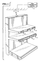
- Figure 1 is a perspective view of a typical electronic display system, including a ceiling mounted transmitting/ receiving antenna and a typical display showcase having multiple displays; and
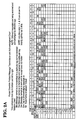
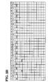
- Figures 2A, 2B and 2C are each a portion of a table showing an example of downlink message communication and the electronic display system algorithm for implementing message pooling in the system shown in Figure 1.
- Electronic display systems have achieved cost effective operation by using modulated back scatter techniques and by not including a radio frequency source in the electronic display units. Because these electronic display units acknowledge messages through the passive technique of modulated back scatter, the available signal to noise ratio near the desired limits of range is limited. The system performance can be improved by repeating identical transmissions to electronic display units near the range limits and recording the strength of the acknowledgement for each transmission. Then, by using statistical techniques, the electronic display system can determine if the message has been received. The electronic display unit's capability to compensate for transmissions that fail because of multipath fading and bit errors is based on a system protocol. This protocol recognizes that a received message is a member of a group of repeated identical transmissions and acknowledges all the messages even if only one is received. To compensate for long term shadowing of electronic display units, if an electronic display unit does not acknowledge, the system will repeat the transmission process several hours later.
- The electronic display system of the preferred embodiment uses modulated back scatter to enable passive receivers to confirm receipt of a message. The confirmation is performed by having the receiver modulate the signal reflected by the antenna at a particular frequency. Referring to Fig.1, each transmitted message is addressed to a particular
electronic display unit 10 and has a time interval reserved for theelectronic display unit 10 to generate an acknowledgement. Thebase communications station 12, including atransmitter 14 and ahomodyne receiver 16, then measures the energy level present in the appropriate frequency and time period. This measurement is called the signal level. Typically, withelectronic display units 10 generating a signal in a multipath transmission environment the signal level has significant random variations from one measurement reading to the next. The receiver also measures the energy present at other frequencies and time periods. This measurement is called the noise level. The noise level may also have a significant random variation from one measurement to another.Base communication station 12 then decides if the signal level is sufficiently high to conclude with the desired confidence level that it could not be caused by noise and therefore must have been caused byelectronic display unit 10 acknowledging the message. - This problem, as described above for
base communication station 12, is a statistical inference problem that is generally solved by the process of hypothesis testing. The hypothesis test has the following components. The null hypothesis is that the signal level does not significantly differ from the population of noise levels; the alternative hypothesis is that the signal level is greater than the noise level with a specified level of confidence. A hypothesis test is then constructed by determining a threshold that the signal level must exceed to reject the null hypothesis. Because the noise level has significant random variation, rejecting the null hypothesis with a high degree of confidence will require that the signal level be large. If multiple independent measurements of the signal level are made and the statistical parameters of the sample are compared with the expected results from an equal size population of noise, the expected variation in a population of noise will be lower than for an individual sample. The law of large numbers states that as the size of a sample increases the variability will decrease. Since the variability has decreased, the signal level necessary to reject the null hypothesis has decreased as well. This implies that if thebase communications station 12 sends multiple identical messages to anelectronic display unit 10 and receives multiple acknowledgements, the signal level of each acknowledgement can be combined into one statistic. The threshold for concluding that the message was received is now reduced as the sample size increases. By using this technique, thebase communications station 12 can detect acknowledgements from otherwise undetectable distantelectronic display units 10. - A precise definition for the following terms will assist in an efficient discussion of message pooling:
- Pooling Uplinks - Grouping the acknowledgments together as described above to reduce the required threshold.
- Pooling Downlinks - Grouping received downlink messages in an
electronic display unit 10 such that if one message in a group of N is received, N acknowledgements are transmitted. The timing of the N acknowledgements is independent of which message is actually received. - Communication Attempt - A group of identical messages that are sent to an
electronic display unit 10 and its associated uplinks, which are evaluated to determine if theelectronic display unit 10 received then. - Downlink Batch Size - The number of downlinks pooled by an
electronic display unit 10. - Small Batch - The smaller of the two downlink batch sizes in a particular system at a particular time.
- Large Batch - The larger of the two downlink batch sizes in a particular system at a particular time.
- Uplink Batch Size - The number of uplinks pooled for a given communication attempt. This may contain one or more downlink batches.
- Downlink Success Rate (DSR) - A particular electronic display unit's fraction of downlink messages that it receives, assuming it is not blocked by some unusual circumstance, for example being blocked by a pallet of cans in the aisle.
- Batch Success Rate (BSR) - The fraction of Downlink Batches for a particular electronic display unit that has one successful message delivered and therefore generates acknowledgements. This also varies based on the downlink batch size.
- Message Success Rate (MSR) - The fraction of messages for a particular
electronic display unit 10 that is received by theelectronic display unit 10 and has a sufficiently strong acknowledgement for thebase communications station 12 to conclude that the message was received. This varies based on downlink and uplink batch sizes. - Signal Level - A numerical value computed by a digital signal processor as a measurement of the energy detected in a narrow band corresponding to the frequency at which a particular
electronic display unit 10 is expected to generate an acknowledgement signal. - Noise Level - A numerical value computed by a digital signal processor as a measurement of the energy detected in a narrow band that is similar to the band containing the acknowledgement but at a different frequency and therefore not materially affected by any electronic display unit's acknowledgement.
- Signal Noise - The signal level for frames in which no acknowledgements were expected (for example,
frame 1 which follows the system information burst). - Broad Band Noise Level - A numerical value computed by a digital signal processor that represents the variance of the time domain digital signal after filtering out 60 Hz. or 50 Hz. harmonics. This value provides a reliable instantaneous measurement of the interference level for a particular frequency hop.
- The discussion of the message pooling protocol and algorithms is broken down into three parts: the first part presents the protocol used to pool downlink messages; the second part presents the statistical procedures and algorithms used to implement the necessary hypothesis tests or to estimate the appropriate pool size for communicating with a particular
electronic display unit 10; and the third part then overviews the communications process with pooling and the data storage capabilities to support it. - Downlink pooling allow the electronic display system to compensate for messages that are not correctly received by more distant
electronic display units 10. The electronic display system is expected to operate in a multipath fading environment. The coherence time of the channel is longer than the downlink message; therefore it can be expected that the entire message will be lost if a deep fade occurs during transmission. The electronic display system does not include an error correction inelectronic display units 10; thus if a single bit in the 127 bit downlink packet is in error, the tag will detect the error using an error detection code and ignore the message. To compensate for the loss of messages, the electronic display system retransmits messages that were not acknowledged. Forelectronic display units 10 in a location that has a poor radio frequency link (sometimes referred to as distant electronic display units), detecting an individual acknowledgement unambiguously is difficult. In these cases it is desirable to send multiple downlinks and receive multiple uplinks in order received to complete communication. If multiple transmissions are sent toelectronic display unit 10, lost transmissions can be compensated for by downlink pooling. - When downlinks are pooled,
electronic display unit 10 that receives a single message will know that the message is a member of a group or batch of N identical messages and responds to all N even though it may have correctly received only one of the messages. Ifelectronic display unit 10 knows just by receiving one message when the acknowledgement for all messages in the batch should occur, it can acknowledge as if it had received all of the messages on the basis of having received just one. Since the messages are identical, it is irrelevant if the tag received more than one of the messages; therefore,electronic display unit 10 acknowledging unreceived messages is useful. One way to implement downlink pooling would be to have each message carry information that would tellelectronic display unit 10 the batch size and when to start acknowledging. However, because communication bandwidth and electronic display unit processing power are typically limited, the electronic display system in accordance with the present invention utilizes a set of restrictive protocols that allowelectronic display unit 10 to determine easily when to acknowledge without adding additional information to each message. - The protocol takes advantage of pre-existing synchronized timing information known to both the
base communication unit 12 and allelectronic display units 10. This information is a Frame Number, which determines which frame within a group of 16 super frames is currently being used, and a Time of Day (TOD) code, which counts the number of super frames (modulo 216) that have occurred since the electronic display system was last initialized. This information is transmitted to the particularelectronic display unit 10 through the System ID Burst. The Time of Day (TOD) code is transmitted in the burst and the burst itself is preferably transmitted inFrame 0; therefore receiving the burst conveys the Frame Number. Since allelectronic display units 10 must correctly receive at least one System Identification Burst before achieving synchronization and being enable for communication, allelectronic display units 10 andbase communication station 12 will have the same value for the Frame Number and the Time of Day (TOD) code. - The protocol uses the following parameters:
- Batch Sizes will be powers of 2 (i.e., 1, 2, 4, 8 or 16).
- All the messages in a batch will be sent in the same Frame and Time Slot of successive super frames (i.e., successive Time of Day (TOD) code values).
- The first downlink in a batch will be sent when Time of Day (TOD) code modulo batch size is 1. Therefore the last will be sent when Time of Day (TOD) code modulo batch size is 0.
- The first acknowledgement will be enabled immediately after the last downlink interval for the batch and will occur in the associated uplink time slot of the next frame. This means that for a batch size of one, timing and protocol are unaffected.
- Frames will have a batch size associated with them, which is rarely changed. The odd frames will have one size (Small Batch) and the even frames will have another (Large Batch).
- The size of Small Batch and Large Batch will be communicated to all of the tags in the System Identification Burst.
- At any one time a particular electronic display unit will be in the process of receiving or acknowledging only one message. Therefore
base communication station 12 will send one batch of messages toelectronic display unit 10 and wait for all the acknowledgements before sending additional messages. For example, ifbase communication station 12 sends a batch of 8 messages to a particularelectronic display unit 10 inFrame 2 beginning at Time of Day (TOD)code 1, the next batch of messages to that particularelectronic display unit 10 may not begin until Time of Day (TOD) code 17. Messages may not be sent to the sameelectronic display unit 10 in other frames either. Broadcast messages that are addressed to allelectronic display units 10 and are not acknowledged may be transmitted at this time. - Once
electronic display unit 10 receives a single downlink message, it will correctly transmit all acknowledgements even if it loses synchronization. - Since the protocol supports only two different size batches, which are seldom changed, these two sizes must be determined so that they provide reasonably efficient communication to the population of
electronic display units 10. The electronic display system supports two different downlink batch sizes simultaneously; these are referred to as Small Batch and Large Batch. The uplink batch sizes will generally be an integer multiple of the downlink batch size that basecommunication station 12 selects for a particularelectronic display unit 10. The electronic display system uses one downlink batch size for odd frames and a different one for even frames; both sizes are broadcast to allelectronic display units 10 in System Information Burst. For simplicity, the Small Batch corresponds to the odd frames and the Large Batch to the even frames. It is assumed that the size of the Large and Small batches will not be changed often. - If all
electronic display units 10 in a given electronic display system do not have the same batch sizes, erratic performance, including false positive acknowledgments, may result. Choosing the optimal size for the downlink batches will involve many tradeoffs and assumptions; however, the following heuristics have been found to produce acceptable results. Selecting a batch size involves a trade-off between having a large batch so that even the weakest tag would have a 99.9% batch success rate (BSR) and having the batch small enough so that most communications are not forced to use more messages than required for other reasons. - The optimal value for the Large Batch size will most likely be determined by the downlink success rate (DSR) of the weakest
electronic display units 10 so that even theseelectronic display units 10 have a batch success rate (BSR) of preferably over 95%. Initially, the weakestelectronic display units 10 will be identified based on experience. In initial determinations, a batch size of 8 was used. - The downlink success rate (DSR) is a metric of system performance and robustness. As the system is tested, the downlink success rate (DSR) of individual
electronic display units 10 can measured using the techniques discussed below and the initial estimate refined. The minimum batch sizes for various values of the downsuccess rate (DSR) and batch success rate are shown in Table 1 below:

- Note that if uplink batch sizes contain several downlink batches, the downlink success rate (BSR) is more critical, and the downlink batch size should then be increased. For downlink sizes greater than 1, it is likely that if one batch fails, the uplink batch also fails. Therefore it is desirable for all downlink batches in an uplink batch to be successful. It is desirable for all batches in a communication attempt to be successful (excluding shadowing).
- For any particular value of Small Batch Size, some portion of
electronic display units 10 will require use of the Large Batch because of a downlink success rate (DSR) that is unacceptably low for using the small batch. As the size of the Small Batch decreases, this portion is reduced. If the portion ofelectronic display units 10 that require the Large Batch exceeds the Large Batch capacity, the Small Batch size should be increased until this condition is eliminated. In initial determinations, the Small Batch size was set at 1. - The batch size for the odd and even frames are conveyed to all
electronic display units 10 in the system identification burst. Each batch size is coded in one nibble using the following code shown in Table 2:

- The codes above are stored by an
electronic display unit 10 and can be used by theelectronic display unit 10 to perform the modulus operation with minimal processing. Anelectronic display unit 10 uses the above codes and bit-wise ANDs them with the least significant nibbles of the Time of Day (TOD) code; the result is Time of Day (TOD) code molulo, and the batch size value. - When
base communication station 12 is turned on and starts transmitting, allelectronic display units 10 are guaranteed to get the correct batch size before they acquire synchronization. If the batch size is modified whilebase communication station 12 is transmitting, care must be taken to avoid erratic operation and possible false positive acknowledgments during the transition period. It is difficult to analyze the complexity of the change-over process and how it will affect communication. The synchronization maintenance algorithm will cause anelectronic display unit 10 to lose synchronization if it does not receive 15 consecutive system information bursts, a process that takes less than six minutes. To change batch sizes, the following steps should be followed: - 1. Wait until any time-critical messages have been sent.
- 2. Complete both downlinks and uplinks for all batches of communication that were started.
- 3. Change desired data in the System Information Burst.
- 4. Transmit dummy messages.
- 5. Wait for 15 super frames.
- 6. Restart communication.
- The actual transmission of a downlink batch and the associated reception of acknowledgments will be implemented by a subroutine that will be called the downlink manager. The downlink batch routine will receive the following information:
- 1. Electronic display unit's 10 identification number
- 2. The content of the message.
- 3. The number of messages in the downlink batch.
- 4. Desired receive antenna mode (scan, selective, omnidirectional).
- 5. If a selective antenna mode is used then the list of enabled antennas for each
base communications station 10 is included. - The downlink manager will maintain a queue for each of the 15 communication frames within a super frame.
Frame 0 is always used for the System Information Burst. The queues will operate using a first in, first out (FIFO) discipline. The downlink manager will respond to queries about the length of both queues. When a request for a downlink batch is received, the downlink manager will perform the following actions to enter messages in the queue: - 1. Check that the number of downlinks corresponds to either the Small Batch or Large Batch. If not it will return an error message that reports the batch sizes.
- 2. Attempt to assign the message to the frame queues with the appropriate batch size that has the shortest length. With two queues of equal length, the downlink manager should assign the message to the one to be transmitted sooner. The downlink manager will check that this assignment will not cause two batches of communications to the same
electronic display unit 10 to overlap. Anelectronic display unit 10 cannot receive a message from one batch while it is receiving or acknowledging a message from a different batch. If an overlap would occur, the downlink manager must take appropriate remedial action. - For each downlink frame, the downlink manager will transmit messages to
base communication station 12 as follows: - 1. If the Time of Day (TOD) code modulo for the batch size appropriate to that frame does not equal one, it will retransmit the message transmitted in that frame, the last super frame.
- 2. If the Time of Day (TOD) code modulo for the batch size appropriate to that frame is 1, the downlink manager will take the next message off the front of the queue for that frame and transmit it. It will also transmit appropriate antenna switch instructions to
base communication station 12. If there are no messages on the queue, it will construct a dummy message appropriate to the frame and transmit that. It may be desirable to adopt rules for constructing dummy messages that enhance synchronization performance. - For every uplink time slot the downlink manager will record the acknowledgement data from
base communication station 12. If the Time of Day (TOD) code modulo for the batch size is one, then the downlink manager will complete the pending request and return all the acknowledgement information to the calling program. If a dummy message was involved, the downlink manager will add the acknowledgement information to the noise data base. - Figure 2 shows an example of downlink message communication and the electronic display system algorithm for implementing pooling.
- In a preferred embodiment of the present invention, there is a subroutine that supports automatic measurement of the Downlink Success Ratio (DSR) associated with a particular
electronic display unit 10 and location. This routine will be given anelectronic display unit 10 identification number, a requested confidence interval, and an indication of how recently theelectronic display unit 10 was moved. The routine will initiate downlink measurements and/or utilize information from a history file and then return the measured Downlink Success Ratio (DSR). This procedure compares the average acknowledgement level from large downlink batches with the average acknowledgement level from unpooled downlinks with a batch size equal to 1. The Downlink Success Ratio (DSR) for anelectronic display unit 10 at a particular location can be estimated using the following formula: - Experimental Determination of Downlink Success Ratio (DSR) using pooling, where:
- xsm - Sample average acknowledgement level without downlink pooling
- µs - Theoretical average acknowledgement level from a given
electronic display unit 10 - µn - Theoretical average noise level


µn = 28; µs = 32; xsm = 30
- For
electronic display units 10 with an uplink signal sufficiently above the noise level, the Downlink Success Ratio (DSR) can be estimated by a method of counting all uplinks above the midpoint between average signal and average noise level as successes and those below as failures. However, the standard error of this technique is difficult to determine analytically. - The Downlink Success Ratio (DSR) of weaker
electronic display units 10 is a metric of electronic display system performance and robustness. This technique can be used to allow automated measurement of the Downlink Success Ratio (DSR) for engineering field trials and customer installations. Before full-scale deployment, an additional test can be made by reducing the transmit power by 3dB or 6dB and remeasuring the Downlink Success Ratio (DSR). This test will demonstrate the margin in the electronic display system, which protects against extreme cases. - The goal of uplink pooling is to allow
base communication station 12 to detect the acknowledgement of weakelectronic display units 10 with a high degree of confidence. The value of uplink pooling can be understood intuitively as follows. A weakelectronic display unit 10 will causebase communication station 12 to detect a higher energy level at the acknowledgement frequency than it otherwise would. However, since the noise level varies, this level may only exceed the distribution of noise levels 90% of the time. If multiple uplinks are grouped together and 90% levels are achieved 5 out of 5 tries, the possibility of this being due to noise is only 1 in 10,000. In considering the possibility of extremely weakelectronic display units 10, even if the signal to noise ration for a weakelectronic display unit 10 is 0dB, the sum of signal plus noise will average 3dB above the noise level. - The following processes should be performed to implement uplink pooling:
- 1. Information about the distribution of signal noise levels must be gathered and analyzed.
- 2. Hypothesis tests should be constructed and thresholds determined.
- 3. A choice of the appropriate downlink batch size is made.
- 4. Messages are sent and a hypothesis test is conducted to obtain an acknowledgement.
- The electronic display system collects and analyzes information about the level and distribution of signal noise. A fundamental assumption behind detection of an uplink signal in the electronic display system is that
base communication station 12 can measure a signal level which is the energy present at a frequency band in which an uplink may have occurred and can determine with sufficient confidence that such a level could not have been due to noise. To facilitate this determination, base communication system should have sufficient information to be able to determine for any particular measurement that the likelihood that a particular signal level occurs is based on noise alone. To determine this likelihood, the electronic display system collects three different data inputs as discussed in further detail below. - The signal noise level is a measurement of the signal level at a time when it is certain that an uplink signal is not present, such as after sending dummy messages. One advantage of this measurement is that it is, by definition, identical in terms of the frequency measured and the measurement techniques to the actual signal level. However, one disadvantage is that the measurement cannot be made at the same time as a real uplink. Because noise levels may change rapidly with time based on both
base communication station 12, as well as any potentially interfering transmitters frequency hopping, the past signal noise levels cannot be relied on to provide sufficient information to predict possible signal levels due to noise for a particular uplink signal. The potential time variation problem is compounded by statistical variations in the signal noise level, which leads to the need for multiple samples in order to predict the probability distribution. However, measuring the signal noise level has been found to be a good way to calibrate and/or check and verify the validity of other estimates of noise and to predict the distribution of signal levels due to noise given other information about the noise level. - The noise level is a measurement of energy at a different frequency with the same band width and similar frequency processing as the signal noise level. This measurement should not be affected by the presence of an uplink at the uplink frequency. This measurement has the advantage of providing a noise estimate about the particular uplink frame being considered and of providing a number of samples in a relatively short period of time while uplink activity is occurring. However, because it is narrow band, it will have significant random variations similar to the signal noise level and independent of the actual noise level. Experimental results without frequency hopping in a non-interference environment show that the statistical parameters and distribution of the Noise Level track the Signal Noise Level well. Until a Broad Band Noise measure is implemented, a sample of at least 100 Noise Level measurements will be used to compute the likelihood of particular Signal Levels occurring due to noise. If necessary, populations of Noise Levels will be gathered for each hop frequency.
- The Broad Band Noise Level will measure the noise over a broad bandwidth that will likely be the bandwidth of the analog filters in
base communication station 12. The advantage of a broad band noise measurement is that it has less statistical variation from sample to sample. Therefore, based on one sample, thebase communication station 12 will have an accurate estimate of the average noise measurement. Prior to computing a broad band noise estimate, the effects of any noise and 60Hz harmonics which will not affect the narrow bank noise should be filtered out. The Signal Noise Level distribution will be predicted from the Broad Band Noise based on fitting experimental data and/or theoretical models. - The statistical techniques used in uplink pooling depend on standard the independence assumption. It is normally necessary to experimentally verify that each sample of signal noise relative to the broad band noise level or the average of the noise level is an independent random variable. It should not be auto-correlated in time or correlated with hop frequency.
- These statistical techniques are potentially sensitive to impulsive noise phenomena, which often occur in many engineering applications. Even though the signal noise levels may apparently closely follow a particular distribution, it is difficult to draw conclusions about values on the tail of a distribution. All signal noise level and noise level samples that are above the 98th percentile based on the probability distribution used in the analysis should be recorded with their time of occurrence and associated broad band noise measurement. These samples are called outliers. It will be most convenient if the list of outliers is sorted by noise level value and the total number of valid samples from which the list was drawn is maintained. If the broad band noise measurement is subject to significant variation, the percentiles and records will be difficult for each group of broad band noise measurements. It is possible that the broad band noise level may fall into two distinct categories of normal and high. Normal levels would show only statistical variations and possible time dependent shifts over the course of several hours or days. High levels would result from interference and be high enough to excludes uplink communication during particular time periods. In this case, the best approach has been found to discard all samples with high noise levels and not use them for uplink purposes.
- Hypothesis testing involves testing a sample against information about the population distribution from which it is drawn and determining the likelihood that a given hypothesis is true. The best known statistical techniques involve determining a null hypothesis and alternative hypothesis, planning an experiment to use a given sample size choosing a statistic, for example the average, and a threshold for that statistic, gathering the data, computing the statistic and rejecting or not rejecting not rejecting the null hypothesis. Because these techniques are well-known and analytically tractable, they are useful for projecting worst case performance.
- Given the nature of the electronic display system in accordance with the present invention, it is more efficient and algorithmically simpler from a decision making point of view to use techniques of sequential analysis. In sequential analysis, the experiment is repeated until either one of two hypotheses has been concluded. While precise values for constructing sequential hypothesis tests are analytically difficult to calculate, good results can be obtained by calculating and using worst case bounds. In a sequential analysis the ratio between the relative likelihood of each independent sample based on both hypotheses are determined.
- The probability that the signal exceeds the minimum signal level will be computed assuming that signal levels are normally distributed in dB around the minimum level with a standard deviation determined by pooling individual
electronic display units 10. Based on initial determinations, this standard deviation should be of the order of 4 to 6dB. - The probability that the sample is based on noise may be estimated in one of two ways. The most direct, but difficult, way is to have a large number of samples of signal noise levels or noise levels all of which were taken under conditions equivalent to the current samples. The probability the signal is based on noise is:

- With approximately 2000 noise samples the above equation will begin to have significant statistical uncertainties above the 98th percentile. To take the worst case of these uncertainties these values are calculated as:
- Let N = number of noise samples ≥ sample
- for N ≥ 5

- for N < 5

- An alternative method is to fit a probability distribution function to the noise data. The choice of function should be supported by both theoretical and experimental data over a variety of conditions. For the electronic display system in accordance with the present invention, a normal distribution in dB is used as an approximation to what may be a Rayleigh distribution. Because implosive noise may occur, that is not covered by the physical properties underlining the majority of points in the distribution, the probability of samples above the 98th percentile should be computed based on the equation above. If, after many electronic display systems have been tested in the field and significant statistical data is available, it is determined that the probability distribution and the experimental data always track well up to a particular percentile, this percentile can be used instead.
- Computationally the most convenient approach is to evaluate each sample the log of the probability ratio shown below:

- For each message the cumulative sum of LPRi is computed after every sample. This sum is then compared against a threshold and one of these four decisions are made:
- 1. An acknowledgement has been received and therefore the message has been delivered.
- 2.
Electronic display unit 10 is not acknowledging due to shadowing or a brokenelectronic display unit 10. Transmission will be attempted several hours later. - 3. There is insufficient data for a reliable conclusion and additional downlink batches are required
- 4. Too many trials were performed, i.e., more than 80, and the operation should be terminated with an assumption of non-acknowledgement. This should be a rare occurrence.
- Three parameters are used to set up a sequential hypothesis test: a false positive rate, a false negative rate and a minimum signal level. The false positive and false negative rates are familiar concepts from basic statistics. The minimum signal level is an extra parameter needed for sequential analysis. Based on these parameters decision thresholds are calculated.
- The false positive rate for each type of communication is derived from marketing level requirements and will vary depending on the type of transaction. For example, a price change message will typically require greater confidence than a bed check. For interim internal stages it may be a matter of convenience. For example, each message in a multi-message update may be sent with an α (false positive rate) of 1 in 200 but the set of messages may then be verified by a single bed check message with an α of 1 in 80,000 to meet customer requirements.
- In deriving α from system requirements, it may be prudent to use the conservative allowance that every price change message will fail the first time and therefore use 1 in the number of messages per year. This assumption is robust and allows the system to retry many times. Provided the average number of transmission attempts per message does not exceed two, the false positive rate will not exceed specification. This means communication attempts should have at least a 50% probability of success.
- A customer-driven false negative rate is typically specified. Because of shadowing by pallets of goods or parked shopping carts,
electronic display unit 10 may be out of communication for several hours. To compensate for this, after a communication attempt fails,base communication station 12 will wait several hours and try again. The false negative rate (β) for pooling applies to a single attempt only. Making β too small will cause the electronic display system to use more messages to determine that theelectronic display unit 10 is shadowed. The electronic display system will probably perform best if β is less than the shadowing probability of the weakerelectronic display units 10. In the preferred embodiment of electronic display system in accordance with the invention, a β of 5% has been assumed. - The sum of β and the shadowing rate, and downlink batch failures, must be less than 50% for all
electronic display units 10 to preserve the false negative rate given the choice of α above. After an upper bound on long term shadowing rates has been established by field experiments, β is chosen and the number of delayed retries needed to meet the marketing requirements for false brokenelectronic display units 10 reports can be calculated as follows. - The number of false broken
electronic display units 10 reports allowed per customer level message is:
- SP = 0.1 - Shadow Probability (assumed)
- β = 0.05 - Hypothesis test false positive
- DF = 0.05 - Uplink Batches that fail due to a Downlink Batch failure (assumed)
- BFP = 1 - (1-SP) · (1 - β) · (1 - DF)
- BFP = 0.188 - Probability of uplink batch failure from all causes
- Then the allowed Long Term Recalls

- ALR=8
- Based on the α and β chosen above the two important decision thresholds (A and B) are defined as follows. If the cumulative test statistic log of the probability ratio (LPR) exceeds the log of A, then the signal level is sufficient to conclude that an acknowledgement occurred. If the cumulative test statistic log of the probability ratio (LPR) is less than the log of B, then
base communication station 12 will conclude that an uplink was not received. The formulas given for calculating A and B are shown below:

- These equations calculate values of A and B that are sufficient to ensure that α and β are better than specified. This should mean that the electronic display system will exceed specifications and ensure customer satisfaction. It should be noted that because this assumes that a perfect uplink is achieved through downlink pooling and no shadowing, the actual communication attempt failure rate will exceed β. However, because of subsequent retransmissions, the customer will not see this.
- The concept of a minimum level is important, since testing continues until one of the two hypotheses is proved. The test will not terminate if a minimum uplink level that exceeds the noise level is not established. If the minimum noise level is too high, weak
electronic display units 10 will be unable to communicate. If it is too low, a large number of tries will be necessary before the electronic display system gives up on a particularelectronic display unit 10 that may be shadowed. While setting this level 2dB above the noise has been found to be acceptable, a more optimal value may be set based on particular field data. If shadowing occurs often, it may be desirable to establish a minimum uplink level on anelectronic display unit 10 toelectronic display unit 10 basis. It may be useful to take the greater of 2dB or 33% of a well-established average signal strength for a particularelectronic display unit 10. Before reporting that a particularelectronic display unit 10 is broken, it is preferable for thebase communication system 12 to retry with the default minimum signal level. Independent of the choice of minimum signal level, the false positive acknowledgement rate will not exceed specifications. - Calculating the expected number of messages to complete communication is analytically difficult. It depends on the uplink signal to noise ratio, the distribution of both signal and noise, the downlink batch size and the downlink success rate. It is best estimated by constructing a Monte Carlo simulation with the desired inputs and running it for 1000 batches.
- An estimate of the number of messages required assuming a perfect downlink can be obtained quickly with the formula below; however the accuracy associated with it is unknown.
α
- A similar estimate of the number of messages required to conclude that a particular
electronic display unit 10 is not acknowledging is:
- The best known way to choose a downlink batch sizes is to estimate the number of messages by simulation as noted above for both batches and then to compute the following ratio:

- If this ratio is greater than one, use the small batch. If it is less than one, use the large batch. If this ratio results in a shortage of capacity for one batch size, switch batches for those situations closest to one. The assignment of a large number of
electronic display units 10 contrary to efficiency may indicate a need to change the sizes of small batch and large batch. - If simulation results are unavailable, the downlink batch size can be selected based on setting a minimum downlink batch success rate. A 90% or better batch success rate is likely to provide good performance unless a large number of batches are needed. The batch size can be selected by using the following equation to estimate batch success rate (BSR) for the small batch:

- If the batch success rate (BSR) for the small batch is too low, use the large batch.
- When a new electronic display system is initially turned on, it will broadcast dummy messages that create an optimal synchronization environment and gather noise background data for several minutes.
- When a new
electronic display unit 10 is introduced into an electronic display system operating environment,base communication station 12 will initially sent a changeelectronic display unit 10 identification number or Self Test message using the large batch. For periods when many newelectronic display units 10 are being introduced, a small batch size of 1 and a large batch size of 16 is recommended. During the uplink it will instructbase communication station 12 to switch between antennas so that each antenna receives an equal share of uplinks. It will perform hypothesis testing on the base communication station and each antenna until one of the signals demonstrates an acknowledgement with an α of 0.0001. At this point it will designate the specific antenna on thebase communications station 12 with the strongest signal, i.e., the greatest Σ log of the probability ratio (LPR), as the primary one and the next strongest signals as the secondary and tertiary ones for that particularelectronic display unit 10. Thebase communication station 12 should then attempt to use a small batch for sending additional information to the particularelectronic display unit 10 such as price information. Based on the success of attempts using a small batch, thebase communication station 12 can estimate the Downlink Success Rate (DSR) and decide if switching back to a large batch is appropriate. Thebase communication station 12 can then communicate normally with that particularelectronic display unit 10. If no antennas can find the particularelectronic display unit 10, it should schedule a retry retransmission several hours later. After a sufficient number of attempts to communicate, that particularelectronic display unit 10 should be reported as broken. - Based on the history of a particular electronic display unit's 10 performance at a given location, i.e., with a particular preferred antenna, the
base communication station 12 estimates the Downlink Success Rate (DSR) of a particularelectronic display unit 10 and chooses an appropriate batch size. Thebase communication station 12 then sends the message to the particularelectronic display unit 10 and waits until: - 1. It has received an uplink with a confidence level appropriate for the message class; or
- 2. It concludes that the particular
electronic display unit 10 is not acknowledging. - If it concludes that the particular
electronic display unit 10 is not acknowledging, it should: - 1. Check the secondary and tertiary antennas for an acknowledgement signal. In some cases, these will be on different
base communication stations 12 and therefore will collect data simultaneously. When reusing the same data on an alternate antenna the value of α should be divided by 3. - 2. Look at the sum of the log of the probability ratio (LPR) values from all successful messages since the particular electronic display unit's 10 identification number was last changed. If this sum is less than 12, it should also attempt to send the particular electronic display unit's 10 identification number command.
- 3. Schedule a communication attempt for several hours later. After several attempts, it should assume that the particular
electronic display unit 10 has moved and follow the procedure described above for newly repositionedelectronic display units 10. It may reuse any available data from other antennas. - If a memory checking self test fails, the
base communication station 12 should re-establish communication by using a self test without the memory test. Once communication is re-established, the memory test should be tried again immediately. Then if it fails, thebase communication station 12 should reload the particular electronic display unit's 10 memory.
Claims (5)
- A wireless communication method including the steps of: transmitting a plurality of message signals from a base communication station (12) addressed to a receiver (10); said receiver transmitting a plurality of acknowledgement signals at a particular frequency upon receipt of at least one of said message signals; said base communication station (12) receiving signals at said particular frequency in time frames corresponding to those in which said acknowledgement signals are transmitted by said receiver (10); and said base communication station (12) comparing the strengths of multiple signals received in said time frames with the strengths of multiple noise signals and, on the basis of this comparison, making a determination as to whether said receiver (10) has acknowledged receipt of a message signal.
- A method according to claim 1, characterized in that said plurality of message signals are identical.
- A method according to either claim 1 or claim 2, characterized in that a plurality of acknowledgement signals at said particular frequency are transmitted by said receiver (10) upon receipt of one message signal.
- A method according to any one of the preceding claims, characterized in that if said base communication station (12) fails to make a determination that said receiver (10) has acknowledged receipt of a message signal then said base communication station (12) transmits a further plurality of message signals, and the remaining steps of claim 1 are repeated.
- A method according to any one the preceding claims, characterized in that said acknowledgement signals are transmitted using a modulated back scatter technique.
Applications Claiming Priority (2)
| Application Number | Priority Date | Filing Date | Title |
|---|---|---|---|
| US348526 | 1994-12-02 | ||
| US08/348,526 US5722048A (en) | 1994-12-02 | 1994-12-02 | Apparatus for improving the signal to noise ratio in wireless communication systems through message pooling and method of using the same |
Publications (3)
| Publication Number | Publication Date |
|---|---|
| EP0715433A2 true EP0715433A2 (en) | 1996-06-05 |
| EP0715433A3 EP0715433A3 (en) | 1999-11-03 |
| EP0715433B1 EP0715433B1 (en) | 2002-11-13 |
Family
ID=23368416
Family Applications (1)
| Application Number | Title | Priority Date | Filing Date |
|---|---|---|---|
| EP95308635A Expired - Lifetime EP0715433B1 (en) | 1994-12-02 | 1995-11-30 | Method for wireless communication by way of repeatedly transmitted messages |
Country Status (7)
| Country | Link |
|---|---|
| US (4) | US5722048A (en) |
| EP (1) | EP0715433B1 (en) |
| JP (1) | JP4368430B2 (en) |
| CA (1) | CA2164285C (en) |
| DE (1) | DE69528808T2 (en) |
| NZ (1) | NZ280545A (en) |
| ZA (1) | ZA9510284B (en) |
Cited By (1)
| Publication number | Priority date | Publication date | Assignee | Title |
|---|---|---|---|---|
| GB2314487A (en) * | 1996-06-17 | 1997-12-24 | Ibm | Method of wireless communication in a network |
Families Citing this family (27)
| Publication number | Priority date | Publication date | Assignee | Title |
|---|---|---|---|---|
| US5722048A (en) * | 1994-12-02 | 1998-02-24 | Ncr Corporation | Apparatus for improving the signal to noise ratio in wireless communication systems through message pooling and method of using the same |
| SE507557C2 (en) * | 1996-07-05 | 1998-06-22 | Ericsson Telefon Ab L M | Method and apparatus for quality determination in a mobile radio communication system |
| US6055414A (en) * | 1996-07-23 | 2000-04-25 | Ncr Corporation | System and method for improving reliability and performance of wireless communication systems using message pooling |
| DE19723331B4 (en) * | 1997-06-04 | 2010-11-11 | Ipcom Gmbh & Co. Kg | radio set |
| US6704133B2 (en) | 1998-03-18 | 2004-03-09 | E-Ink Corporation | Electro-optic display overlays and systems for addressing such displays |
| US7075502B1 (en) * | 1998-04-10 | 2006-07-11 | E Ink Corporation | Full color reflective display with multichromatic sub-pixels |
| US6872883B2 (en) * | 1998-10-19 | 2005-03-29 | Thomas A. Ginsburg | Mast lighting system |
| WO2001019651A1 (en) * | 1999-09-15 | 2001-03-22 | Scheffer Ronald L | Method and apparatus for securing a shopping cart |
| US6648103B2 (en) * | 1999-09-15 | 2003-11-18 | Ronald Scheffer | Method and apparatus for securing a shopping cart |
| US7000737B2 (en) * | 1999-09-15 | 2006-02-21 | Ronald Scheffer | Method and apparatus for securing a shopping cart |
| US20040172401A1 (en) * | 2000-06-15 | 2004-09-02 | Peace Terrence B. | Significance testing and confidence interval construction based on user-specified distributions |
| US6847976B1 (en) * | 2000-06-15 | 2005-01-25 | Terrence B. Peace | Method and apparatus for significance testing and confidence interval construction based on user-specified distribution |
| SE0002573D0 (en) * | 2000-07-07 | 2000-07-07 | Pricer Ab | Price label communication system |
| US6503062B1 (en) * | 2000-07-10 | 2003-01-07 | Deka Products Limited Partnership | Method for regulating fluid pump pressure |
| SE0202565D0 (en) * | 2002-08-28 | 2002-08-28 | Pricer Ab | Electronic pricing system, device and method |
| US6980784B1 (en) | 2002-10-15 | 2005-12-27 | Ncr Corporation | System and method of reducing noise in an electronic shelf label system |
| US6977627B1 (en) * | 2002-10-15 | 2005-12-20 | Ncr Corporation | Electronic sign with oppositely facing electronic displays |
| US7099307B2 (en) * | 2003-05-07 | 2006-08-29 | Qwest Communications International Inc. | Automated cross-box and methods for using an automated cross-box |
| US6931024B2 (en) * | 2003-05-07 | 2005-08-16 | Qwest Communications International Inc. | Systems and methods for providing pooled access in a telecommunications network |
| US7672872B2 (en) * | 2003-08-22 | 2010-03-02 | Smurfit-Stone Container Enterprises, Inc. | Point-of-purchase display with RFID inventory control |
| KR100754937B1 (en) * | 2006-03-30 | 2007-09-03 | 인하대학교 산학협력단 | A multi-step channel prediction apparatus and method for adaptive transmission in ofdm/fdd system |
| WO2007148635A1 (en) * | 2006-06-20 | 2007-12-27 | Ntt Docomo, Inc. | Radio communication device and method used in mobile communication system |
| US8787344B2 (en) * | 2006-08-30 | 2014-07-22 | Qualcomm Incorporated | Method and apparatus for ACKCH with repetition in orthogonal systems |
| DE102007054592B4 (en) * | 2007-11-15 | 2014-04-30 | Siemens Aktiengesellschaft | Plug connection device, designed to connect two functional elements for signal and power transmission |
| JP5405846B2 (en) * | 2009-02-06 | 2014-02-05 | セイコーインスツル株式会社 | Electronic shelf label terminal, electronic shelf label system |
| CN108784154A (en) * | 2018-06-12 | 2018-11-13 | 黄河科技学院 | A kind of displaying device based on Internet of Things |
| CN112087740B (en) * | 2020-09-18 | 2022-11-15 | 深圳赛时达科技有限公司 | Data transmission method of electronic price tag system and electronic price tag system |
Family Cites Families (33)
| Publication number | Priority date | Publication date | Assignee | Title |
|---|---|---|---|---|
| US3831095A (en) * | 1973-03-26 | 1974-08-20 | G Mounce | Receiver system having multiple contributing channels |
| US4075632A (en) * | 1974-08-27 | 1978-02-21 | The United States Of America As Represented By The United States Department Of Energy | Interrogation, and detection system |
| US4654880A (en) * | 1983-12-09 | 1987-03-31 | Minnesota Mining And Manufacturing Company | Signal transmission system |
| US4888767A (en) * | 1984-12-25 | 1989-12-19 | Nec Corporation | Repeat request signal transmission method for multi-station packet communication |
| FR2578126B1 (en) * | 1985-02-26 | 1992-01-03 | Lecheviller Jean Pierre | TELEPHONE APPARATUS WITH FIXED TERMINAL AND MOBILE HANDSET |
| GB8512340D0 (en) | 1985-05-15 | 1986-10-29 | Gec Avionics | Measuring dynamic system |
| US4786907A (en) * | 1986-07-14 | 1988-11-22 | Amtech Corporation | Transponder useful in a system for identifying objects |
| US4739328A (en) | 1986-07-14 | 1988-04-19 | Amtech Corporation | System for identifying particular objects |
| US4766295A (en) * | 1987-03-02 | 1988-08-23 | H.E. Butt Grocery Company | Electronic pricing display system |
| US4905234A (en) * | 1987-06-03 | 1990-02-27 | General Electric Company | Apparatus and method for transmitting digital data over a radio communications channel |
| US5572653A (en) * | 1989-05-16 | 1996-11-05 | Rest Manufacturing, Inc. | Remote electronic information display system for retail facility |
| US5406271A (en) * | 1989-12-23 | 1995-04-11 | Systec Ausbausysteme Gmbh | System for supplying various departments of large self-service stores with department-specific information |
| US5299117A (en) * | 1990-01-02 | 1994-03-29 | Rest Manufacturing, Inc. | Power conserving receiver operation for a remote electronic display system |
| FR2658645B1 (en) * | 1990-02-16 | 1994-10-07 | Sitour Electronic Systems | INSTALLATION COMPRISING A SET OF REMOTE CONTROL DISPLAY MODULES. |
| WO1992006454A1 (en) * | 1990-10-05 | 1992-04-16 | Diablo Research Corporation | Method and apparatus for price display |
| JPH0563615A (en) * | 1991-08-30 | 1993-03-12 | Ncr Corp | Capacitive coupling device |
| US5465085A (en) * | 1992-02-13 | 1995-11-07 | Display Network, Inc. | Retail store display system |
| DE4205239A1 (en) * | 1992-02-21 | 1993-08-26 | Sel Alcatel Ag | MOBILE TEST DEVICE FOR A MOBILE RADIO SYSTEM |
| US5396651A (en) * | 1992-04-01 | 1995-03-07 | The Boeing Company | Radio communication system including indication that communication link is established |
| SG50659A1 (en) * | 1992-04-10 | 1998-07-20 | Ericsson Ge Mobile Inc | Random access in mobile telephone system |
| US5465405A (en) * | 1992-07-30 | 1995-11-07 | Raytheon Company | Apparatus and method for detecting signals |
| SE470518B (en) * | 1992-11-09 | 1994-06-27 | Pricer Norden Ab | Procedure and apparatus for receipt of information |
| US5745775A (en) * | 1992-11-13 | 1998-04-28 | Pricer Inc. | Remotely adjustable price display module |
| US5348485A (en) * | 1993-04-12 | 1994-09-20 | Electronic Retailing Systems Int'l Inc. | Electronic price display system with vertical rail |
| GB9309246D0 (en) * | 1993-05-05 | 1993-06-16 | Esselte Meto Int Gmbh | Rechargeable shelf edge tag |
| GB9309353D0 (en) * | 1993-05-06 | 1993-06-16 | Ncr Int Inc | Wireless communication system having antenna diversity |
| US5442343A (en) * | 1993-06-21 | 1995-08-15 | International Business Machines Corporation | Ultrasonic shelf label method and apparatus |
| US5450612A (en) * | 1993-08-26 | 1995-09-12 | Motorola, Inc. | Communication system for communicating with a plurality of selective call receivers and method therefor |
| US5841365A (en) * | 1993-09-22 | 1998-11-24 | Seattle Silicon Corporation | Method and apparatus for communicating with a product label |
| US5659761A (en) * | 1994-10-18 | 1997-08-19 | Hand Held Products | Data recognition apparatus and portable data reader having power management system |
| US5722048A (en) * | 1994-12-02 | 1998-02-24 | Ncr Corporation | Apparatus for improving the signal to noise ratio in wireless communication systems through message pooling and method of using the same |
| US5751257A (en) * | 1995-04-28 | 1998-05-12 | Teletransactions, Inc. | Programmable shelf tag and method for changing and updating shelf tag information |
| US5754754A (en) * | 1995-07-26 | 1998-05-19 | International Business Machines Corporation | Transmission order based selective repeat data transmission error recovery system and method |
-
1994
- 1994-12-02 US US08/348,526 patent/US5722048A/en not_active Expired - Lifetime
-
1995
- 1995-11-28 NZ NZ280545A patent/NZ280545A/en unknown
- 1995-11-30 EP EP95308635A patent/EP0715433B1/en not_active Expired - Lifetime
- 1995-11-30 DE DE69528808T patent/DE69528808T2/en not_active Expired - Lifetime
- 1995-12-01 CA CA002164285A patent/CA2164285C/en not_active Expired - Lifetime
- 1995-12-04 JP JP33769595A patent/JP4368430B2/en not_active Expired - Fee Related
- 1995-12-04 ZA ZA9510284A patent/ZA9510284B/en unknown
-
1997
- 1997-09-04 US US08/923,809 patent/US6137990A/en not_active Expired - Lifetime
- 1997-09-04 US US08/923,806 patent/US6049699A/en not_active Expired - Lifetime
- 1997-09-04 US US08/923,792 patent/US6353746B1/en not_active Expired - Lifetime
Non-Patent Citations (1)
| Title |
|---|
| None |
Cited By (2)
| Publication number | Priority date | Publication date | Assignee | Title |
|---|---|---|---|---|
| GB2314487A (en) * | 1996-06-17 | 1997-12-24 | Ibm | Method of wireless communication in a network |
| GB2314487B (en) * | 1996-06-17 | 2001-01-10 | Ibm | Method of wireless communication in a network |
Also Published As
| Publication number | Publication date |
|---|---|
| JP4368430B2 (en) | 2009-11-18 |
| US6137990A (en) | 2000-10-24 |
| EP0715433B1 (en) | 2002-11-13 |
| CA2164285C (en) | 2003-01-07 |
| JPH08251046A (en) | 1996-09-27 |
| US6353746B1 (en) | 2002-03-05 |
| CA2164285A1 (en) | 1996-06-03 |
| DE69528808T2 (en) | 2003-12-24 |
| DE69528808D1 (en) | 2003-01-16 |
| US6049699A (en) | 2000-04-11 |
| EP0715433A3 (en) | 1999-11-03 |
| AU3916395A (en) | 1996-06-13 |
| US5722048A (en) | 1998-02-24 |
| AU702627B2 (en) | 1999-02-25 |
| NZ280545A (en) | 1997-03-24 |
| ZA9510284B (en) | 1996-06-11 |
Similar Documents
| Publication | Publication Date | Title |
|---|---|---|
| EP0715433B1 (en) | Method for wireless communication by way of repeatedly transmitted messages | |
| US8155061B2 (en) | Method of and system for transmitting signals using frequency hopping | |
| US8638709B2 (en) | Methods and apparatus for conducting financial transactions | |
| USRE41471E1 (en) | Method of Addressing Messages and Communications System | |
| US6959199B2 (en) | Multicast signal transmission power control method and base station using the same | |
| EP1855260B1 (en) | Fire alarm system | |
| US20080180222A1 (en) | Method of communicating in a radio frequency identification system using aloha networks | |
| EP0749092B1 (en) | An electronic price label (EPL) system | |
| US6055414A (en) | System and method for improving reliability and performance of wireless communication systems using message pooling | |
| CA2402143C (en) | Apparatus for improving the signal to noise ratio in wireless communication systems through message pooling and method of using the same | |
| US20030169700A1 (en) | Power margin control | |
| US6757548B1 (en) | Method and apparatus in a wireless messaging system for estimating and using required delivery parameters to meet a target transmission reliability | |
| CN114374994A (en) | Method for reporting and receiving beam failure information, terminal and network equipment | |
| US7417545B1 (en) | Method of determining failure of a communication base station | |
| WO2002021704A2 (en) | Power margin control | |
| JPH11243406A (en) | Data communication method, communication terminal and terminal controller | |
| EP1598991A1 (en) | Method of and system for transmitting signals using frequency hopping | |
| JPH0695655B2 (en) | Wireless zone determination method |
Legal Events
| Date | Code | Title | Description |
|---|---|---|---|
| PUAI | Public reference made under article 153(3) epc to a published international application that has entered the european phase |
Free format text: ORIGINAL CODE: 0009012 |
|
| AK | Designated contracting states |
Kind code of ref document: A2 Designated state(s): DE FR GB |
|
| PUAL | Search report despatched |
Free format text: ORIGINAL CODE: 0009013 |
|
| AK | Designated contracting states |
Kind code of ref document: A3 Designated state(s): DE FR GB |
|
| 17P | Request for examination filed |
Effective date: 20000503 |
|
| 17Q | First examination report despatched |
Effective date: 20010427 |
|
| GRAG | Despatch of communication of intention to grant |
Free format text: ORIGINAL CODE: EPIDOS AGRA |
|
| RTI1 | Title (correction) |
Free format text: METHOD FOR WIRELESS COMMUNICATION BY WAY OF REPEATEDLY TRANSMITTED MESSAGES |
|
| RTI1 | Title (correction) |
Free format text: METHOD FOR WIRELESS COMMUNICATION BY WAY OF REPEATEDLY TRANSMITTED MESSAGES |
|
| GRAG | Despatch of communication of intention to grant |
Free format text: ORIGINAL CODE: EPIDOS AGRA |
|
| GRAH | Despatch of communication of intention to grant a patent |
Free format text: ORIGINAL CODE: EPIDOS IGRA |
|
| GRAH | Despatch of communication of intention to grant a patent |
Free format text: ORIGINAL CODE: EPIDOS IGRA |
|
| GRAA | (expected) grant |
Free format text: ORIGINAL CODE: 0009210 |
|
| AK | Designated contracting states |
Kind code of ref document: B1 Designated state(s): DE FR GB |
|
| REG | Reference to a national code |
Ref country code: GB Ref legal event code: FG4D |
|
| REF | Corresponds to: |
Ref document number: 69528808 Country of ref document: DE Date of ref document: 20030116 |
|
| ET | Fr: translation filed | ||
| PLBE | No opposition filed within time limit |
Free format text: ORIGINAL CODE: 0009261 |
|
| STAA | Information on the status of an ep patent application or granted ep patent |
Free format text: STATUS: NO OPPOSITION FILED WITHIN TIME LIMIT |
|
| 26N | No opposition filed |
Effective date: 20030814 |
|
| REG | Reference to a national code |
Ref country code: GB Ref legal event code: 746 Effective date: 20091111 |
|
| PGFP | Annual fee paid to national office [announced via postgrant information from national office to epo] |
Ref country code: GB Payment date: 20141127 Year of fee payment: 20 Ref country code: DE Payment date: 20141128 Year of fee payment: 20 Ref country code: FR Payment date: 20141118 Year of fee payment: 20 |
|
| REG | Reference to a national code |
Ref country code: DE Ref legal event code: R071 Ref document number: 69528808 Country of ref document: DE |
|
| REG | Reference to a national code |
Ref country code: GB Ref legal event code: PE20 Expiry date: 20151129 |
|
| PG25 | Lapsed in a contracting state [announced via postgrant information from national office to epo] |
Ref country code: GB Free format text: LAPSE BECAUSE OF EXPIRATION OF PROTECTION Effective date: 20151129 |