EP0715466A2 - Image processing apparatus, communication device and system thereof - Google Patents
Image processing apparatus, communication device and system thereof Download PDFInfo
- Publication number
- EP0715466A2 EP0715466A2 EP95308587A EP95308587A EP0715466A2 EP 0715466 A2 EP0715466 A2 EP 0715466A2 EP 95308587 A EP95308587 A EP 95308587A EP 95308587 A EP95308587 A EP 95308587A EP 0715466 A2 EP0715466 A2 EP 0715466A2
- Authority
- EP
- European Patent Office
- Prior art keywords
- video
- data
- image
- processing apparatus
- image processing
- Prior art date
- Legal status (The legal status is an assumption and is not a legal conclusion. Google has not performed a legal analysis and makes no representation as to the accuracy of the status listed.)
- Granted
Links
Images


Classifications
-
- H—ELECTRICITY
- H04—ELECTRIC COMMUNICATION TECHNIQUE
- H04N—PICTORIAL COMMUNICATION, e.g. TELEVISION
- H04N7/00—Television systems
- H04N7/14—Systems for two-way working
- H04N7/15—Conference systems
Definitions
- the present invention relates to an image processing apparatus, a communication device and a system thereof, particularly to a video communication device required for displaying image data and a system thereof.
- an image provided by a video camera is transmitted and displayed via a network.
- a concern of the present invention is to provide an image processing apparatus, a video communication device and a system thereof wherein all or each of the above-described problems are/is solved.
- Another concern of the present invention is to provide an image processing process which enables reading video data stored in a video storage apparatus with complete control, a video communication device and a system thereof.
- Another concern of the present invention is to provide an image processing process which enables reading video data stored in a video storage apparatus via a communication line with complete control, a video communication device and a system thereof.
- image processing apparatus provided with first means for supplying an input image to first display means to achieve real-time display and second means for supplying the image prior by predetermined time of the input image to second display means to achieve real-time display.
- Another concern of the present invention is to provide an image processing apparatus, a communication device or a system thereof provided with a new function.
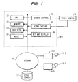
- Fig. 1 is a schematic block diagram showing an embodiment according to the present invention.
- a video server 12 and a plurality of computers 14-1, 14-2 and 14-3 are connected to a network 10 and video cameras 16-1 to 16-3 as image input means are connected to each computer 14-1 to 14-3.
- Each computer 14-1 to 14-3 is basically constituted similarly and is provided with CPU 20 for controlling the entire computer, memory 22 which is the main storage of CPU 20, a hard disk 24 as a secondary memory, a bit map display 26, a mouse 28 as a pointing device, a camera control circuit 30 for controlling a pan, a tilt, zooming in and out and a focus of the connected video cameras 16 and a video capture circuit 32 for fetching video output from the connected video cameras 14 in the corresponding computers 14.
- This embodiment is provided with the current mode in which video output from a video camera 16 connected directly to a computer or to the other computer is reproduced and displayed at a real time and the past mode in which a video data file stored in a video server 12 is reproduced and displayed.
- a video server according to this embodiment is constituted by a well-known system called Redundant Array of Inexpensive Disc (RAID) and enables concurrent writing and reading of dynamic image data.
- RAID Redundant Array of Inexpensive Disc
- Fig. 2 shows access to a file in the current mode
- Fig. 3 shows a flowchart of operation in the current mode.
- files 1, 2, etc. are a series of files consisting of digital video data provided by the same one video camera 16 and divided every given time T0 and numbers are allocated to them in the order of generation.
- Tb shows time in which video data is not read for processing for dividing into files. It is naturally preferable that Tb is as short as possible and Tb can be substantially removed by securing sufficient capacity of a buffer.
- "t" shows the current time
- tp shows the time of the past video (frame) displayed together with the current video (frame)
- Ts shows the difference of time between the current and past video concurrently displayed.
- "tp" is equal to a value obtained by subtracting Ts from "t”.
- a value obtained by adding T0 and Tb is set to a smaller value than Ts. That is, the past video concurrently displayed is stored in a file prior by one or more depending upon the ratio of Ts to T0.
- Ts is first set (S1) and current time data is set to a variable t showing the current time (S2).
- An activated video browser starts displaying an image provided by a specified video camera 16 in the main window of a bit map display 26 and continues to display an image in the main window at a real time until termination is specified (S3, S7).
- the past mode In the past mode, the main reproduced video is displayed in the main window and the past and future images of which difference in time is equivalent to 2Ts with the main reproduced video in the middle of the time 2Ts are displayed in an individual subwindow as a static image.
- the past and future static images are respectively updated to such images after 2Ts elapses at the appropriate timing.
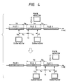
- Fig. 4 shows access in the past mode
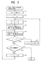
- Fig. 5 shows a flowchart in the past mode.
- t' shows the time in which a frame is displayed in the main window or a frame pointer and it is equivalent to the center in time between the past and future images displayed in the subwindow or a frame pointer.
- tp shows the time prior by Ts to tc or a frame pointer and
- tc shows the time for reproduction to be started and determined by a viewer.
- a viewer If video is displayed in the past mode, a viewer first sets the time tc of a frame of which reproduction is to be started and Ts which defines images prior and later how in time with tc in the center are displayed in a subwindow (S11). "tc” is set to “t'" (S12). "tp” and “tf” are calculated based upon tc and Ts (S13). The frames at the time tp and at the time tf are read of a series of video files and are displayed in respective subwindows (S14).
- a frame at the time t' of which initial value is tc is fetched of a series of video files similarly and is displayed in the main window (S15).
- Each frame is serially reproduced and displayed (S15) adding the time dt between frames to the time t' (S19) until an instruction for termination is input (S18).
- the past dynamic image between tp and tf based upon tc and Ts arbitrarily set can be displayed in the main window and the frames at the time tp and at the time tf can be displayed in a respective subwindow.
- a dynamic image but a static image is displayed in a subwindow only one circuit for reproducing a dynamic image for the main window is required and a dynamic image can be provided at a low cost.
- a static image displayed in a subwindow is updated every 2Ts, it can be also considered a so-called low-speed dynamic image and a system efficient for the cost can be provided.
- tc and Ts may be input to CPU 20 using an input device such as a mouse shown in Fig. 1.
- Figs. 6 and 7 show examples of an operator panel and a display screen of a bit map display 26.
- Fig. 6 shows the screen when the current mode is selected and
- Fig. 7 shows the screen when the past mode is selected. In both cases, a physical arrangement such as the position of a button is the same.
- a reference number 40 designates the main window for displaying video
- a reference number 42 designates a dialog for setting tc in case video is displayed in the main window 40 in the past mode
- a reference number 44 designates a dialog for setting Ts.
- a reference number 46 designates a subwindow for displaying a frame at the time tp
- a reference number 48 designates a subwindow for setting a frame at the time tf.
- a reference number 50 designates a time slider bar for specifying the time between tp and tf of a frame to be displayed in the main window 40 and displaying the frame and the time slider bar is available only when the past mode is selected.
- a reference number 52 designates a time gauge between tp and tf.
- Reference numbers 54, 56, 58, 60, 62 and 64 respectively designate a reproduction control button for controlling video (a dynamic image) between tp and tf displayed in the main window 40.
- the button 54 is used for specifying processing for subtracting 2Ts from a value of tc
- the button 56 is used for specifying processing for rewinding
- the button 58 is used for specifying processing for reproduction
- the button 60 is used for specifying processing for a pause
- the button 62 is used for specifying processing for a rapid traverse
- the button 64 is used for specifying processing for adding 2Ts to a value of tc.
- a reference number 66 designates a current mode button for setting the current mode and a reference number 68 designates a past mode button for setting the past mode.
- a reference number 70 designates a continuous reproduction mode button and a reference number 72 designates an interval reproduction mode button.
- Continuous reproduction is enabled by pressing the continuous reproduction mode button 70.
- a dynamic image can be reproduced only in the interval between tp and tf basically defined based upon tc and Ts, however, if continuous reproduction is enabled, tc is automatically updated when a frame at the time tf is reproduced and reproduction in a new interval is continued.
- continuous reproduction mode without limitation on an interval between tp and tf is enabled. Continuous reproduction can be invalidated by pressing the interval reproduction mode button 72.
- Reference numbers 74 to 86 respectively designate a button for operating a camera and a reference number 88 designates a panel for operating a camera.
- the button 74 is used for specifying a pan to the left side of a camera
- the button 76 is used for specifying a pan to the right side
- the button 78 is used for specifying an upward tilt
- the button 80 is used for specifying a downward tilt
- the button 82 is used for specifying an operation for directing a camera to the center.
- the button 84 is used for specifying operation for increasing the magnifying power of the lens, that is, movement to a telephoto lens
- the button 86 is used for specifying operation for reducing the magnifying power of the lens, that is, movement to a wide angle lens.
- the operator panel 88 shows the direction and the magnifying power of the camera by the position and the size of a four-sided figure in a frame and also displays the current status.
- the dialog for setting tc 42, the time slider bar 50, the time gauge 52, the buttons 54 to 64, the current mode button 66, the continuous reproduction mode button 70 and the interval reproduction mode button 72 are enabled only in the past mode.
- the past mode button 68, the buttons for operating a camera 74 to 86 and the panel for operating a camera 88 are enabled only in the current mode. Disabled objects are displayed in gray out or are not displayed.
- a pan, a tilt and zooming of a specified camera can be operated by pressing an appropriate button of the buttons for operating a camera 74 to 86 or operating the panel for operating a camera 88.
- a mouse button is clicked at an arbitrary point in a window, the coordinates at that point can be fetched.
- a camera can be panned or tilted so that the clicked point is in the center using such a function and further, a camera can zoom in or out so that an appropriate range can be photographed. For instance, when an object or a person to be taken notice of is clicked, a camera can be controlled so that the camera is directed in the direction.
- reproduction can be controlled by pressing an appropriate button of the reproduction control buttons 54 to 64 which function as reproduction control buttons provided to a video tape recorder.
- the buttons 54 and 64 are provided with characteristics peculiar to this embodiment and are used for changing an interval in time specified by the time gauge 52.
- Ts 5 (min.)
- tc three thirty in the afternoon
- tp three twenty-five in the afternoon
- tf three thirty-five in the afternoon
- the button 54 is clicked, tc is changed to three twenty in the afternoon, inevitably, tp is changed to three fifteen in the afternoon and tf is changed to three twenty-five in the afternoon.
- the button 64 is clicked, tc is changed to three forty in the afternoon. That is, video like that by a movie film is enabled on the three screens of the subwindow 46, the main window 40 and the subwindow 48 by clicking the buttons 54 and 64 many times.
- the subwindows 46 and 48 can be changed in the dialog 44, a viewer can view at an arbitrary interval in time.
- This function is very effective in case the system is used for instance as a crime prevention camera system or a monitoring camera system.
- any video recorded on the video tape must be reproduced and displayed by a rapid traverse when change in video is searched, however, according to this embodiment, the video can be accessed without continuation in time and the time required for finding a necessary point can be reduced substantially.
- Continuous reproduction is enabled by pressing the continuous reproduction mode button 70. Basically, only video between tp and tf is displayed, however, if continuous reproduction is validated, tc is automatically updated when a frame at the time tf is reproduced and reproduction at a new interval is continued. As a result, in the continuous reproduction mode, video is continuously reproduced without limitation on the interval between tp and tf. Continuous reproduction can be invalidated by pressing the interval reproduction mode button 72.
- a series of video can be effectively viewed and the operations can be also extremely easy by adopting a graphical user interface as shown in this embodiment.
- Fig. 8 is a block diagram showing a video communication system according to this embodiment.
- reference numbers 101 to 106 respectively designate a video camera
- reference numbers 111 to 116 respectively designate a video communication device
- a reference number 120 designates a video storage apparatus.
- the video camera are connected respectively to video communication devices 111 to 116.
- a reference number 130 designates a network for connecting the video communication devices 111 to 116 and the video storage apparatus 120, and a local area network (LAN) and a wide area network (WAN) such as the telephone network, ISDN and the common carrier leased line are included.
- LAN local area network
- WAN wide area network
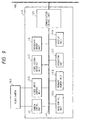
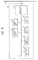
- Fig. 9 is a block diagram showing video communication devices 111 to 116 according to this embodiment.
- a reference number 101 designates a video camera
- a reference number 100 designates an internal bus
- a reference number 121 designates a camera control apparatus for controlling a pan, a tilt and zooming of the camera 101.
- a reference number 122 designates a video input control apparatus for fetching in the video communication device after a video signal fetched from a video camera is converted from analog to digital
- a reference number 123 designates a video encoding/decoding apparatus for compressing or decompressing digital video information
- a reference number 124 designates a main control apparatus for controlling all the video communication devices 121
- a reference number 125 designates a primary storage for storing a variety of processing procedures (programs), communication data and control information
- a reference number 126 designates a secondary memory which enables high-speed writing/reading of data.
- a reference number 127 designates an operation apparatus for a pointing device (mouse)
- a reference number 128 designates a display apparatus such as a bit map display
- a reference number 129 designates a communication control apparatus for controlling communication with a network 130.
- Fig. 10 is a block diagram showing a video storage apparatus 120 according to this embodiment.
- a reference number 200 designates an internal bus
- a reference number 203 designates a video encoding/decoding apparatus (CODEC) for compressing or decompressing digital video information
- a reference number 204 designates a main control apparatus for controlling the entire video storage apparatus 120.
- a reference number 205 designates a primary storage for storing a variety of processing procedures (programs), communication data and control information
- a reference number 206 designates a secondary memory which enables high-speed writing/reading of data
- a reference number 207 designates an operation apparatus for a pointing device (mouse).
- a reference number 208 designates a display apparatus such as a bit map display and a reference number 209 designates a communication control apparatus for controlling communication with a network 130.
- Figs. 11 to 13 are flowcharts showing operation of the video communication devices 111 to 116 according to this embodiment.
- Figs. 14 and 15 are flowcharts showing operation of the video storage 120 apparatus according to this embodiment.
- Fig. 16 shows an example of the screen displaying the entire display apparatus 118 of the video communication devices 111 to 116 according to this embodiment.
- Each video communication device 111 to 116 according to this embodiment is a terminal used for, for instance a video conference or a visual telephone and video windows 910 to 960 corresponding to each participant of a video conference are shown in Fig. 16.
- reference numbers 910 to 960 designate video windows for receiving and displaying video transmitted by the video communication devices 111 to 116 to which video cameras 101 to 106 are connected
- reference numbers 911 to 961 respectively designate a status for displaying the name of a calling party and the time in which video is input corresponding to each video window 910 to 960.
- Fig. 16 shows an example of the screen for displaying individual video in a display section 118 of the video communication devices 111 to 116 according to this embodiment.
- a reference number 1010 designates a video window for receiving and displaying video transmitted by the specified one of the video communication devices 111 to 116.
- Reference numbers 1020 and 1030 designate camera control panels for controlling the video cameras 101 to 106 via a camera control apparatus 111 and they issue an instruction to the camera control apparatus 111 by clicking a variety of graphical user interfaces (GUI) via a mouse to enable a pan, a tilt (1020) and zooming (1030) of a camera.
- GUI graphical user interfaces
- a reference number 1050 designates a time specification panel for inputting a time and when a time is input to a time input field 1051 and a setting button 1052 is clicked, dynamic image data stored in the video storage apparatus 120 is accessed to retrieve data corresponding to the specified time.
- a reference number 1040 designates a switch for switching video from the video communication devices 111 to 116 and reading dynamic image data stored in the video storage apparatus 120, and when the current mode button 1041 is clicked, video transmitted by the video communication devices 111 to 116 is displayed in a dynamic image display window 1010.
- the past mode button 1042 is clicked, dynamic image data stored in the video storage apparatus 120 is read and displayed in the dynamic image display window 1010.
- a time is input to a time specification panel 1050 and a setting button 1052 is clicked, dynamic image data stored in the video storage apparatus 20 is retrieved and displayed.
- Fig. 18 shows an example of a data format used for the video communication system according to this embodiment and the format is constituted by a header comprising fields 141 to 145 and data 146.
- the header 141 to 145 comprises a packet type field 141 for specifying a variety of communication commands, a calling party's name field 142 for writing the name of a calling party, a called party's name field 143 for writing the name of a called party, a media type field 144 for writing a media type of a character, a static image, voice and a dynamic image and the other field 145 for writing the other additional information. All media which may be handled as digital data may be written to the data field 146.
- the video communication device 111 executes the following processing according to a mail processing program stored in a primary storage 125 under control by a main control apparatus 124.
- a step S401 generation of an event is awaited.
- processing proceeds to a step S402 and in the step, it is checked whether the type of the event is an instruction for operating a camera or not. If the type of the event is an instruction for operating a camera, processing proceeds to a step S403 and in the step, video cameras 101 to 104 are controlled via a camera control apparatus 111.
- a command for operating a camera comprises tilt ( ⁇ ), pan ( ⁇ ), zoom (z) ... (1) and according to these commands, a tilt, a pan and zooming of a camera are controlled.
- a tilt ( ⁇ ) command is called increasing/decreasing an angle ⁇ .
- a pan ( ⁇ ) command is called increasing/decreasing an angle ⁇ .
- a zoom (z) command is called increasing/decreasing the magnifying power z of zooming.
- operations of a camera may be instructed by the local video communication device or by the remote video communication device.
- step S402 if the type of an event is not an instruction for operating a camera, processing proceeds to a step S404 and in the step, it is checked whether there is an input to a camera or not. If the video camera 101 connected to the video communication device 111 is normally operated, processing proceeds to the step S404 and in the step, a video signal fetched by a video input control apparatus 112 is converted from analog to digital.
- processing proceeds to a step S406 and in the step, digital video data is compressed by video CODEC 113, processing proceeds to a step S407 and after a communication data format described later is generated, the compressed digital video data is transmitted to the network 130 via a communication control apparatus 119.
- communication data is required to comply with the format shown in Fig.
- a code showing "transmission of video” is written to the packet type field 141
- the name of the video communication device 111 is written to the calling party's name filed 142
- the name of the other video communication devices 112 to 116 or the video storage apparatus 120 is written to the called party's name field 143
- a code showing "a dynamic image” is written to the media type field 144
- the time in which video is fetched is written to the other field 145
- digitized video data is written to the data field 146.
- a broadcast address by which any device in a network can be specified may be used. Further, if necessary, "a multicast address” by which a specific plural devices can be specified or “a unicast address” by which a specific device can be specified may be used.
- video information is transmitted at a real time form each video communication device 111 to 116 to the network 130.
- step S501 generation of an event is awaited.
- processing proceeds to a step S502 and in the step, it is checked whether the type of the event is reception of video or not.
- step S503 in the step, the entire video display processing shown in an example of the screen in Fig. 16 is performed and processing is returned to the step S501. If the name in the called party's name field 104 does not show the local video communication device, the received data is discarded.
- processing proceeds to a step S504 and in the step, it is checked whether a specific calling party of video is selected or not. Operations for selecting a specific calling party of video is performed by clicking an arbitrary one video window of video windows 910 to 960 shown in Fig. 16. If a specific calling party of video, for instance one of the windows 910 to 960 shown in Fig. 16 is selected in the step S504 by the operation apparatus 117 shown in Fig. 9, processing proceeds to a step S505 and in the step, video retrieval processing described later is performed and processing is returned to the step S501.
- step S601 a data field 146 of received video data is read and digital video data is decompressed by video CODEC 113.
- processing proceeds to a step S602 and in the step, a calling party's name field 142 is read to identify the calling party of video.
- step S603 it is checked whether video windows 910 to 960 on the display screen shown in Fig. 16 are empty or not. If they are empty, processing proceeds to a step S604 and in the step, received video data is displayed in a video window corresponding to a calling party of video. Concurrently, the time in which video is fetched from the other field 45 is read and the time is displayed together with the name of a calling party in any of statuses 911 to 961.
- received video data is displayed in a video window corresponding to the name of a calling party obtained in the step S602.
- step S603 processing is terminated without proceeding to the step S604 because data is stored in all the video windows on the display screen shown in Fig. 16.
- video windows are provided, however, seven video windows or more, or six video windows or less may be provided. In a word, the number of video windows may be changed depending upon that of calling parties of video in a network.
- the number of calling parties of video concurrently displayed may be increased by creating a new screen with more video windows.
- video transmitted from the video communication devices 111 to 116 to the network 130 can be received and displayed at a real time.
- a specific calling party of video is selected in a step S504 shown in Fig. 12, the following individual video display processing shown in Fig. 14 is performed.
- a step S701 it is checked whether an individual video display screen shown in Fig. 17 is generated in a display apparatus 208 of the video communication device 115 or not. If an individual video display screen is not generated, processing proceeds to a step S702 and in the step, an individual video display screen shown in Fig. 17 is generated.
- a step S703 it is checked whether the current mode button 1041 shown in Fig. 17 is selected or not. If the current mode button 1041 is selected, processing proceeds to a step S704 and in the step, it is checked whether an instruction for operating a camera is issued in the camera control panels 1020 and 1030 or not.
- processing proceeds to a step S705 and in the step, control over a camera corresponding to an instruction for operating a camera is applied to a calling party of video.
- camera control information according to a format shown in Fig. 18 is transmitted to a calling party of video, for instance video communication devices 111 to 116 shown in Fig. 8.
- a code showing "control over a camera" is written to the packet type field 141, the name of the local video communication device 115 is written to the calling party's name field 142, the name of a calling party obtained in the step S602 shown in Fig.
- processing proceeds to a step S706 and in the step, magnified received video is displayed in a video window 1010 shown in Fig. 17 and processing is terminated.
- a video window 1010 shown in Fig. 17 is larger than the entire video windows 910 to 960 shown in Fig. 16, magnified video can be displayed.
- step S707 if it is detected that the past mode button 1042 shown in Fig. 17 is selected, processing proceeds to a step S708 and in the step, the following processing for retrieving and displaying the past image is performed.
- step S708 completion of the operation for setting the time at which video is input is awaited.
- processing proceeds to a step S709 and in the step, the time input to the time input field 1051 is read.
- processing proceeds to a step S710 and in the step, video data corresponding to the set time is required to the video storage apparatus 120 shown in Fig. 8.
- a code showing "video data required" is written to the packet type field 141 according to a format shown in Fig. 18, the name of the local video communication device 115 is written to a calling party's name field 142, the name of the video storage apparatus 120 is written to a called party's name field 143, a code showing "control data" is written to the media type field 144, and communication data to which the set time is written is generated in the other field 145 and is transmitted to the network 130 via the communication control apparatus 119.
- the video storage apparatus 120 receives data according to a format shown in Fig. 8 and transmits required video data.
- processing proceeds to a step S711 and in the step, video data transmitted by the video storage apparatus 120 is received from the network 130 via the communication control apparatus 129 .
- the data field 146 in received video data is read and digital video data is decompressed by video CODEC 113.
- processing proceeds to a step S713 and in the step, received video data is magnified in adjustment with the size of the video window 1010 on the individual video display screen shown in Fig. 17 and is displayed in the video window 1010.
- the past video of video fetched from a remote video camera can be continuously retrieved based upon the current video and displayed.
- step S801 generation of an event is awaited. If an event is generated, processing proceeds to a step S802 and in the step, it is checked whether the type of the event is reception of video or not. If the packet type field 141 is checked and a code showing "transmission of video" is identified when communication data shown in Fig. 18 is received from the network 130 via the communication control apparatus 209 shown in Fig. 10, processing proceeds to a step S803 and in the step, video data storage processing described below is performed. In the step S803, data in a calling party's name field 142 is read to identify the calling party of video.
- data in the other field 145 is read to obtain time information comprising video.
- Video data written to the data field 146 is read and the video data is stored in an area in the secondary memory 206 corresponding to the calling party of the video together with the time information. If the name stored in a called party's name field 143 does not show the local video storage apparatus, the received data is discarded.
- step S802 if the type of an event is not reception of video, processing proceeds to a step S804 and in the step, it is checked whether video data is required by video communication devices 111 to 116 or not. If communication data including a code showing "video data required" is received from the network 130 via the communication control apparatus 209 shown in Fig. 10 and is written to the packet type field 141, processing proceeds to a step S805 and in the step, the name of a requiring video communication device written to a calling party's name field 142 and time information set in the other field 145 are obtained.
- processing proceeds to a step S806, in the step, data is retrieved using the name of the requiring video communication device and the set time information as a key and desired video data is read from the secondary memory 206 shown in Fig. 10.
- processing proceeds to a step S807 and in the step, after a communication data format described later is generated, it is transmitted to the network 130 via the communication control apparatus 209.
- the communication data complies with a format shown in Fig. 11, a code showing "transmission of video" is written to the packet type field 141, the name of the video storage apparatus 120 is written to a calling party's name field 142, the name of the requiring video communication device is written to a called party's name field 143, a code showing "a dynamic image" is written to the media type field 144, time information is written to the other field 145 and video data is written to the data field 146.
- the past images required by video communication devices 111 to 116 can be transmitted to the network 130.
- the present invention may be applied to a system constituted by a plurality of devices or may be applied to a system comprising one device.
- the number of video communication devices is not limited to six.
- the present invention can be applied to a system or a device on which a program is running.
- a transmission means for transmitting request data for requiring either image data of an image input to another different from the above-described information communication device or an image at an arbitrary time stored in the above-described storage and a receiving means for receiving transmission data transmitted in response to the above-described request data by the above-described another information communication device or the above-described storage, the current video provided by another information communication device and an image formerly obtained can be continuously retrieved and displayed on the system.
Landscapes
- Engineering & Computer Science (AREA)
- Multimedia (AREA)
- Signal Processing (AREA)
- Two-Way Televisions, Distribution Of Moving Picture Or The Like (AREA)
Abstract
Description
- The present invention relates to an image processing apparatus, a communication device and a system thereof, particularly to a video communication device required for displaying image data and a system thereof.
- If digital video data is reproduced as a dynamic image by a computer, in the prior art a digital video data file is successively read and displayed on the screen of a monitor after a file is decompressed in case it is compressed. Therefore, normally only an image at a time in a video data file can be seen. According to the prior art, video data consisting of different files cannot be reproduced and displayed continuously.
- For instance, if the past video data stored in a video server is desired to be read when the current image provided by a video camera connected to a computer in a network is communicated to another computer via the network and is recorded in the video server in the network as a file divided every given time, repetitive work in which another file is read after reading a file is completed is required.
- To know how an image changes after given time elapses when a reproduced image is seen, an operation for reading, reproducing and displaying another file is required if the image exists in another file, and manual setting of time is required even if the image exists in the same file.
- Furthermore, in a video conference system and a supervisory control system for monitoring a remote status, an image provided by a video camera is transmitted and displayed via a network.
- In the meantime, a system in which an image provided by a video camera is digitized, compressed according to an image coding scheme such as Moving Picture Experts Group (MPEG) and Joint Photographic Coding Experts Group (Motion JPEG) if necessary and stored in an image database exists.
- However, if the past image of the current one provided by a camera is retrieved because a system for transmitting and displaying a remote image and a system retrieving and displaying an image stored in an image database are separate, both systems must be activated individually.
- Also, as both systems are separate, an image cannot be retrieved and displayed continuously from the past to the present and the operations are also inconsistent.
- A concern of the present invention is to provide an image processing apparatus, a video communication device and a system thereof wherein all or each of the above-described problems are/is solved.
- Another concern of the present invention is to provide an image processing process which enables reading video data stored in a video storage apparatus with complete control, a video communication device and a system thereof.
- Another concern of the present invention is to provide an image processing process which enables reading video data stored in a video storage apparatus via a communication line with complete control, a video communication device and a system thereof.
- In accordance with the present invention there is provided image processing apparatus provided with first means for supplying an input image to first display means to achieve real-time display and second means for supplying the image prior by predetermined time of the input image to second display means to achieve real-time display.
- Further, another concern of the present invention is to provide an image processing apparatus, a communication device or a system thereof provided with a new function.
- The other features and characteristics of the present invention will be disclosed by description of embodiments and the drawings described below.
-
- Fig. 1 is a schematic block diagram according to an embodiment of the present invention;
- Fig. 2 shows access to a file in the current mode;
- Fig. 3 is a flowchart of displaying video data in the current mode;
- Fig. 4 shows access to a file in the past mode;
- Fig. 5 is a flowchart of displaying video data in the past mode;
- Fig. 6 shows a graphical user interface in the current mode;
- Fig. 7 shows a graphical user interface in the past mode;
- Fig. 8 is a block diagram of a video communication system according to a second embodiment of a present invention;
- Fig. 9 is a block diagram showing a video communication device according to a second embodiment of the present invention;
- Fig. 10 is a block diagram showing a video storage apparatus shown in Fig. 8 according to a second embodiment of the present invention;
- Fig. 11 is a flowchart showing operation in video transmission processing by a video communication device shown in Fig. 9 according to a second embodiment of the present invention;
- Fig. 12 is a flowchart showing operation in video receiving processing by a video communication device according to a second embodiment of the present invention;
- Fig. 13 is a flowchart showing operation in video display processing by a video communication device according to a second embodiment of the present invention;
- Fig. 14 is a flowchart showing operation in video retrieval processing by a video storage apparatus according to a second embodiment of the present invention;
- Fig. 15 is a flowchart showing operation in video storage processing by a video storage apparatus according to a second embodiment of the present invention;
- Fig. 16 shows an example of an entire video display screen by a video communication device according to a second embodiment of the present invention;
- Fig. 17 shows an example of an individual video display screen by a video communication device according to a second embodiment of the present invention; and
- Fig. 18 shows an example of a communication data format according to a second embodiment of the present invention.
- Referring to the drawings, preferred embodiments according to the present invention will be described in detail below.
- Fig. 1 is a schematic block diagram showing an embodiment according to the present invention. A
video server 12 and a plurality of computers 14-1, 14-2 and 14-3 are connected to anetwork 10 and video cameras 16-1 to 16-3 as image input means are connected to each computer 14-1 to 14-3. Each computer 14-1 to 14-3 is basically constituted similarly and is provided withCPU 20 for controlling the entire computer,memory 22 which is the main storage ofCPU 20, ahard disk 24 as a secondary memory, abit map display 26, amouse 28 as a pointing device, acamera control circuit 30 for controlling a pan, a tilt, zooming in and out and a focus of the connectedvideo cameras 16 and avideo capture circuit 32 for fetching video output from the connected video cameras 14 in the corresponding computers 14. - This embodiment is provided with the current mode in which video output from a
video camera 16 connected directly to a computer or to the other computer is reproduced and displayed at a real time and the past mode in which a video data file stored in avideo server 12 is reproduced and displayed. A video server according to this embodiment is constituted by a well-known system called Redundant Array of Inexpensive Disc (RAID) and enables concurrent writing and reading of dynamic image data. - First, the current mode will be described below. Fig. 2 shows access to a file in the current mode and Fig. 3 shows a flowchart of operation in the current mode.
- Referring to Fig. 2,
files video camera 16 and divided every given time T0 and numbers are allocated to them in the order of generation. Tb shows time in which video data is not read for processing for dividing into files. It is naturally preferable that Tb is as short as possible and Tb can be substantially removed by securing sufficient capacity of a buffer. "t" shows the current time, tp shows the time of the past video (frame) displayed together with the current video (frame) and Ts shows the difference of time between the current and past video concurrently displayed. "tp" is equal to a value obtained by subtracting Ts from "t". In this embodiment, a value obtained by adding T0 and Tb is set to a smaller value than Ts. That is, the past video concurrently displayed is stored in a file prior by one or more depending upon the ratio of Ts to T0. - When the current mode is activated for instance by operating a mouse shown in Fig. 1, Ts is first set (S1) and current time data is set to a variable t showing the current time (S2). An activated video browser starts displaying an image provided by a specified
video camera 16 in the main window of abit map display 26 and continues to display an image in the main window at a real time until termination is specified (S3, S7). - When time specified for Ts elapses (S4) since displaying a video signal provided by a
video camera 16 in the main window is started, displaying a frame at the time tp prior by Ts to the current time t in a subwindow is started (S5), a variable t is updated (S2) and elapse by Ts is again awaited. As it is warranted that a frame at the time tp is recorded as a file without fail according to a condition, "T0 + Tb < TS", the frame may be read from the file. However, exceptionally, the time tp may be just in the range of Tb and in this case, a frame at the nearest time prior to the time tp of the files in which video is recorded may be selected. - If Ts must be changed on the way (S6), operation is restarted from S1 at that time.
- As described above, as the current video and the video prior by time defined as Ts are concurrently displayed according to the current mode in this embodiment as shown in Fig. 3, change of time can be readily checked and when the current video is to be taken notice of, it can be checked by checking the past video in detail. Such a function is very useful for a variety of monitoring camera systems.
- Next, the past mode will be described. In the past mode, the main reproduced video is displayed in the main window and the past and future images of which difference in time is equivalent to 2Ts with the main reproduced video in the middle of the time 2Ts are displayed in an individual subwindow as a static image. The past and future static images are respectively updated to such images after 2Ts elapses at the appropriate timing. Fig. 4 shows access in the past mode and Fig. 5 shows a flowchart in the past mode.
- Referring to Fig. 4, "t'" shows the time in which a frame is displayed in the main window or a frame pointer and it is equivalent to the center in time between the past and future images displayed in the subwindow or a frame pointer. "tp" shows the time prior by Ts to tc or a frame pointer and "tf" shows the time later by Ts than tc or a frame pointer. That is, tc = tp + Ts = tf - Ts. "tc" shows the time for reproduction to be started and determined by a viewer.
- If video is displayed in the past mode, a viewer first sets the time tc of a frame of which reproduction is to be started and Ts which defines images prior and later how in time with tc in the center are displayed in a subwindow (S11). "tc" is set to "t'" (S12). "tp" and "tf" are calculated based upon tc and Ts (S13). The frames at the time tp and at the time tf are read of a series of video files and are displayed in respective subwindows (S14).
- Next, a frame at the time t' of which initial value is tc is fetched of a series of video files similarly and is displayed in the main window (S15). Each frame is serially reproduced and displayed (S15) adding the time dt between frames to the time t' (S19) until an instruction for termination is input (S18).
- If the time t' is equal to tf in the meanwhile (S16), it is added by 2Ts to tc (S17), tp and tf of the new tc are again calculated (S13) and images to be displayed in subwindows are updated (S14).
- Though action in case Ts is changed on the way of reproduction is omitted in Fig. 5, in that case operation may be restarted from a step S11.
- As described above, the past dynamic image between tp and tf based upon tc and Ts arbitrarily set can be displayed in the main window and the frames at the time tp and at the time tf can be displayed in a respective subwindow. As not a dynamic image but a static image is displayed in a subwindow, only one circuit for reproducing a dynamic image for the main window is required and a dynamic image can be provided at a low cost. As a static image displayed in a subwindow is updated every 2Ts, it can be also considered a so-called low-speed dynamic image and a system efficient for the cost can be provided.
- In this embodiment, tc and Ts may be input to
CPU 20 using an input device such as a mouse shown in Fig. 1. - Figs. 6 and 7 show examples of an operator panel and a display screen of a
bit map display 26. Fig. 6 shows the screen when the current mode is selected and Fig. 7 shows the screen when the past mode is selected. In both cases, a physical arrangement such as the position of a button is the same. - Referring to Figs. 6 and 7, a
reference number 40 designates the main window for displaying video, areference number 42 designates a dialog for setting tc in case video is displayed in themain window 40 in the past mode, and areference number 44 designates a dialog for setting Ts. Areference number 46 designates a subwindow for displaying a frame at the time tp and areference number 48 designates a subwindow for setting a frame at the time tf. - A
reference number 50 designates a time slider bar for specifying the time between tp and tf of a frame to be displayed in themain window 40 and displaying the frame and the time slider bar is available only when the past mode is selected. Areference number 52 designates a time gauge between tp and tf. -
Reference numbers main window 40. Thebutton 54 is used for specifying processing for subtracting 2Ts from a value of tc, thebutton 56 is used for specifying processing for rewinding, thebutton 58 is used for specifying processing for reproduction, thebutton 60 is used for specifying processing for a pause, thebutton 62 is used for specifying processing for a rapid traverse and thebutton 64 is used for specifying processing for adding 2Ts to a value of tc. - A
reference number 66 designates a current mode button for setting the current mode and areference number 68 designates a past mode button for setting the past mode. - A
reference number 70 designates a continuous reproduction mode button and areference number 72 designates an interval reproduction mode button. Continuous reproduction is enabled by pressing the continuousreproduction mode button 70. In this embodiment, a dynamic image can be reproduced only in the interval between tp and tf basically defined based upon tc and Ts, however, if continuous reproduction is enabled, tc is automatically updated when a frame at the time tf is reproduced and reproduction in a new interval is continued. As a result, in the continuous reproduction mode, continuous reproduction without limitation on an interval between tp and tf is enabled. Continuous reproduction can be invalidated by pressing the intervalreproduction mode button 72. -
Reference numbers 74 to 86 respectively designate a button for operating a camera and areference number 88 designates a panel for operating a camera. Thebutton 74 is used for specifying a pan to the left side of a camera, thebutton 76 is used for specifying a pan to the right side, thebutton 78 is used for specifying an upward tilt, thebutton 80 is used for specifying a downward tilt and thebutton 82 is used for specifying an operation for directing a camera to the center. Thebutton 84 is used for specifying operation for increasing the magnifying power of the lens, that is, movement to a telephoto lens and thebutton 86 is used for specifying operation for reducing the magnifying power of the lens, that is, movement to a wide angle lens. Theoperator panel 88 shows the direction and the magnifying power of the camera by the position and the size of a four-sided figure in a frame and also displays the current status. - The dialog for setting
tc 42, thetime slider bar 50, thetime gauge 52, thebuttons 54 to 64, thecurrent mode button 66, the continuousreproduction mode button 70 and the intervalreproduction mode button 72 are enabled only in the past mode. In the meantime, thepast mode button 68, the buttons for operating acamera 74 to 86 and the panel for operating acamera 88 are enabled only in the current mode. Disabled objects are displayed in gray out or are not displayed. - In the current mode, a pan, a tilt and zooming of a specified camera can be operated by pressing an appropriate button of the buttons for operating a
camera 74 to 86 or operating the panel for operating acamera 88. In a window display system, when a mouse button is clicked at an arbitrary point in a window, the coordinates at that point can be fetched. When an arbitrary point on the screen of themain window 40 is clicked, a camera can be panned or tilted so that the clicked point is in the center using such a function and further, a camera can zoom in or out so that an appropriate range can be photographed. For instance, when an object or a person to be taken notice of is clicked, a camera can be controlled so that the camera is directed in the direction. - In the current mode, a frame at the time tp is displayed in the
left subwindow 46. This provides plainness sensible by intuition.CPU 20 controls a bit map display so that a message or a mark showing the system is in the current mode is displayed in theright subwindow 48. - In the past mode, reproduction can be controlled by pressing an appropriate button of the
reproduction control buttons 54 to 64 which function as reproduction control buttons provided to a video tape recorder. Thebuttons time gauge 52. In Fig. 7, an example in which Ts = 5 (min.), tc = three thirty in the afternoon, tp = three twenty-five in the afternoon and tf = three thirty-five in the afternoon is shown, however, when thebutton 54 is clicked, tc is changed to three twenty in the afternoon, inevitably, tp is changed to three fifteen in the afternoon and tf is changed to three twenty-five in the afternoon. When thebutton 64 is clicked, tc is changed to three forty in the afternoon. That is, video like that by a movie film is enabled on the three screens of thesubwindow 46, themain window 40 and thesubwindow 48 by clicking thebuttons - Further, as the interval in time of a frame displayed in the
main window 40, thesubwindows dialog 44, a viewer can view at an arbitrary interval in time. This function is very effective in case the system is used for instance as a crime prevention camera system or a monitoring camera system. In case anything is always photographed by a camera, in the case of a video tape, any video recorded on the video tape must be reproduced and displayed by a rapid traverse when change in video is searched, however, according to this embodiment, the video can be accessed without continuation in time and the time required for finding a necessary point can be reduced substantially. - As video at three times can be concurrently seen, change can be readily found. For instance, the system is also effective for a person who is late for a video conference to understand the outline of the entire conference for a short time. Continuous reproduction is enabled by pressing the continuous
reproduction mode button 70. Basically, only video between tp and tf is displayed, however, if continuous reproduction is validated, tc is automatically updated when a frame at the time tf is reproduced and reproduction at a new interval is continued. As a result, in the continuous reproduction mode, video is continuously reproduced without limitation on the interval between tp and tf. Continuous reproduction can be invalidated by pressing the intervalreproduction mode button 72. - A series of video can be effectively viewed and the operations can be also extremely easy by adopting a graphical user interface as shown in this embodiment.
- As understandable readily by the description above, as according to this embodiment a series of video files divided every given time can be continuously handled, a viewer can access to video files for a long time without being conscious of each file. By this, really required sections can be readily fetched from massive video data.
- Also, as the current video or video at the required time and the past image or the past and future images are concurrently displayed, change in video can be compared on the screens. The change in video is readily sensible and a desired point can be readily found. As the past and future images are displayed as a static image, a circuit for display can be simple and a very effective video display system at a low cost can be provided.
- Referring to the drawings, a second embodiment according to the present invention will be described below.
- Fig. 8 is a block diagram showing a video communication system according to this embodiment.
- Referring to Fig. 8,
reference numbers 101 to 106 respectively designate a video camera,reference numbers 111 to 116 respectively designate a video communication device and areference number 120 designates a video storage apparatus. The video camera are connected respectively tovideo communication devices 111 to 116. - A
reference number 130 designates a network for connecting thevideo communication devices 111 to 116 and thevideo storage apparatus 120, and a local area network (LAN) and a wide area network (WAN) such as the telephone network, ISDN and the common carrier leased line are included. - Fig. 9 is a block diagram showing
video communication devices 111 to 116 according to this embodiment. - Referring to Fig. 9, a
reference number 101 designates a video camera, a reference number 100 designates an internal bus and areference number 121 designates a camera control apparatus for controlling a pan, a tilt and zooming of thecamera 101. Areference number 122 designates a video input control apparatus for fetching in the video communication device after a video signal fetched from a video camera is converted from analog to digital, areference number 123 designates a video encoding/decoding apparatus for compressing or decompressing digital video information, and areference number 124 designates a main control apparatus for controlling all the video communication devices 121 Areference number 125 designates a primary storage for storing a variety of processing procedures (programs), communication data and control information, and a reference number 126 designates a secondary memory which enables high-speed writing/reading of data. Areference number 127 designates an operation apparatus for a pointing device (mouse), areference number 128 designates a display apparatus such as a bit map display, and areference number 129 designates a communication control apparatus for controlling communication with anetwork 130. - Fig. 10 is a block diagram showing a
video storage apparatus 120 according to this embodiment. - Referring to Fig. 10, a
reference number 200 designates an internal bus, areference number 203 designates a video encoding/decoding apparatus (CODEC) for compressing or decompressing digital video information, and areference number 204 designates a main control apparatus for controlling the entirevideo storage apparatus 120. Areference number 205 designates a primary storage for storing a variety of processing procedures (programs), communication data and control information, areference number 206 designates a secondary memory which enables high-speed writing/reading of data,anda reference number 207 designates an operation apparatus for a pointing device (mouse). Areference number 208 designates a display apparatus such as a bit map display and areference number 209 designates a communication control apparatus for controlling communication with anetwork 130. - Figs. 11 to 13 are flowcharts showing operation of the
video communication devices 111 to 116 according to this embodiment. - Figs. 14 and 15 are flowcharts showing operation of the
video storage 120 apparatus according to this embodiment. - Fig. 16 shows an example of the screen displaying the entire display apparatus 118 of the
video communication devices 111 to 116 according to this embodiment. Eachvideo communication device 111 to 116 according to this embodiment is a terminal used for, for instance a video conference or a visual telephone andvideo windows 910 to 960 corresponding to each participant of a video conference are shown in Fig. 16. - Referring to Fig. 16,
reference numbers 910 to 960 designate video windows for receiving and displaying video transmitted by thevideo communication devices 111 to 116 to whichvideo cameras 101 to 106 are connected, andreference numbers 911 to 961 respectively designate a status for displaying the name of a calling party and the time in which video is input corresponding to eachvideo window 910 to 960. - Fig. 16 shows an example of the screen for displaying individual video in a display section 118 of the
video communication devices 111 to 116 according to this embodiment. - Referring to Fig. 17, a
reference number 1010 designates a video window for receiving and displaying video transmitted by the specified one of thevideo communication devices 111 to 116.Reference numbers video cameras 101 to 106 via acamera control apparatus 111 and they issue an instruction to thecamera control apparatus 111 by clicking a variety of graphical user interfaces (GUI) via a mouse to enable a pan, a tilt (1020) and zooming (1030) of a camera. - A
reference number 1050 designates a time specification panel for inputting a time and when a time is input to atime input field 1051 and asetting button 1052 is clicked, dynamic image data stored in thevideo storage apparatus 120 is accessed to retrieve data corresponding to the specified time. - A
reference number 1040 designates a switch for switching video from thevideo communication devices 111 to 116 and reading dynamic image data stored in thevideo storage apparatus 120, and when thecurrent mode button 1041 is clicked, video transmitted by thevideo communication devices 111 to 116 is displayed in a dynamicimage display window 1010. When thepast mode button 1042 is clicked, dynamic image data stored in thevideo storage apparatus 120 is read and displayed in the dynamicimage display window 1010. When a time is input to atime specification panel 1050 and asetting button 1052 is clicked, dynamic image data stored in thevideo storage apparatus 20 is retrieved and displayed. - Fig. 18 shows an example of a data format used for the video communication system according to this embodiment and the format is constituted by a header comprising fields 141 to 145 and data 146.
- The header 141 to 145 comprises a packet type field 141 for specifying a variety of communication commands, a calling party's name field 142 for writing the name of a calling party, a called party's name field 143 for writing the name of a called party, a media type field 144 for writing a media type of a character, a static image, voice and a dynamic image and the other field 145 for writing the other additional information. All media which may be handled as digital data may be written to the data field 146.
- The details of video transmission processing in the
video communication device 111 constituted as described above according to this embodiment will be described below based upon a flowchart shown in Fig. 11. However, as described above, thevideo communication device 111 executes the following processing according to a mail processing program stored in aprimary storage 125 under control by amain control apparatus 124. - First, in a step S401, generation of an event is awaited. When an event is generated, processing proceeds to a step S402 and in the step, it is checked whether the type of the event is an instruction for operating a camera or not. If the type of the event is an instruction for operating a camera, processing proceeds to a step S403 and in the step,
video cameras 101 to 104 are controlled via acamera control apparatus 111. - A command for operating a camera comprises tilt (θ), pan (φ), zoom (z) ... (1) and according to these commands, a tilt, a pan and zooming of a camera are controlled.
- These commands are allocated to
camera control panels camera control panel 1020 is pressed, a tilt (θ) command is called increasing/decreasing an angle θ. Similarly, while a left-hand/right-hand button in thecamera control panel 1020 is pressed, a pan (φ) command is called increasing/decreasing an angle φ. When a scroll bar in thecamera control panel 1030 is operated, a zoom (z) command is called increasing/decreasing the magnifying power z of zooming. - However, operations of a camera may be instructed by the local video communication device or by the remote video communication device.
- In the step S402, if the type of an event is not an instruction for operating a camera, processing proceeds to a step S404 and in the step, it is checked whether there is an input to a camera or not. If the
video camera 101 connected to thevideo communication device 111 is normally operated, processing proceeds to the step S404 and in the step, a video signal fetched by a videoinput control apparatus 112 is converted from analog to digital. - Next, processing proceeds to a step S406 and in the step, digital video data is compressed by
video CODEC 113, processing proceeds to a step S407 and after a communication data format described later is generated, the compressed digital video data is transmitted to thenetwork 130 via a communication control apparatus 119. In this case, communication data is required to comply with the format shown in Fig. 18, a code showing "transmission of video" is written to the packet type field 141, the name of thevideo communication device 111 is written to the calling party's name filed 142, the name of the othervideo communication devices 112 to 116 or thevideo storage apparatus 120 is written to the called party's name field 143, a code showing "a dynamic image" is written to the media type field 144, the time in which video is fetched is written to the other field 145 and digitized video data is written to the data field 146. - For the above-described name of a called party, "a broadcast address" by which any device in a network can be specified may be used. Further, if necessary, "a multicast address" by which a specific plural devices can be specified or "a unicast address" by which a specific device can be specified may be used.
- By the above-described processing, video information is transmitted at a real time form each
video communication device 111 to 116 to thenetwork 130. - Next, the details of video receiving processing by a
video communication device 115 according to this embodiment will be described below based upon a flowchart shown in Fig. 12. - First, in a step S501, generation of an event is awaited. When an event is generated, processing proceeds to a step S502 and in the step, it is checked whether the type of the event is reception of video or not.
- If communication data shown in Fig. 18 is received from the
network 130 via thecommunication control apparatus 129 shown in Fig. 9, the packet type field 141 is checked, if a code showing "transmission of video" is identified, processing proceeds to a step S503, in the step, the entire video display processing shown in an example of the screen in Fig. 16 is performed and processing is returned to the step S501. If the name in the called party'sname field 104 does not show the local video communication device, the received data is discarded. - If the type of an event is not reception of video in the step S502, processing proceeds to a step S504 and in the step, it is checked whether a specific calling party of video is selected or not. Operations for selecting a specific calling party of video is performed by clicking an arbitrary one video window of
video windows 910 to 960 shown in Fig. 16. If a specific calling party of video, for instance one of thewindows 910 to 960 shown in Fig. 16 is selected in the step S504 by the operation apparatus 117 shown in Fig. 9, processing proceeds to a step S505 and in the step, video retrieval processing described later is performed and processing is returned to the step S501. - Next, referring to a flowchart shown in Fig. 13, the details of video display processing by a
video communication device 115 according to this embodiment will be described. - If video data is received in the step S502 shown in Fig. 12, the following the entire video display processing shown in Fig. 13 is performed. First, in a step S601, a data field 146 of received video data is read and digital video data is decompressed by
video CODEC 113. Next, processing proceeds to a step S602 and in the step, a calling party's name field 142 is read to identify the calling party of video. Further, processing proceeds to a step S603 and in the step, it is checked whethervideo windows 910 to 960 on the display screen shown in Fig. 16 are empty or not. If they are empty, processing proceeds to a step S604 and in the step, received video data is displayed in a video window corresponding to a calling party of video. Concurrently, the time in which video is fetched from theother field 45 is read and the time is displayed together with the name of a calling party in any ofstatuses 911 to 961. - If a plurality of calling parties of video exist in the
network 130, received video data is displayed in a video window corresponding to the name of a calling party obtained in the step S602. - In the meantime, if seven terminals or more of calling parties of video exist in the
network 130, video signals for six terminals are already received and a video signal is transmitted from the seventh terminal, in the step S603 processing is terminated without proceeding to the step S604 because data is stored in all the video windows on the display screen shown in Fig. 16. - In this embodiment, six video windows are provided, however, seven video windows or more, or six video windows or less may be provided. In a word, the number of video windows may be changed depending upon that of calling parties of video in a network.
- In such a case, the number of calling parties of video concurrently displayed may be increased by creating a new screen with more video windows.
- By the above-described processing, video transmitted from the
video communication devices 111 to 116 to thenetwork 130 can be received and displayed at a real time. - Next, referring to a flowchart shown in Fig. 14, the details of video retrieval processing by the
video communication device 115 according to this embodiment will be described below. - If a specific calling party of video is selected in a step S504 shown in Fig. 12, the following individual video display processing shown in Fig. 14 is performed.
- First, in a step S701, it is checked whether an individual video display screen shown in Fig. 17 is generated in a
display apparatus 208 of thevideo communication device 115 or not. If an individual video display screen is not generated, processing proceeds to a step S702 and in the step, an individual video display screen shown in Fig. 17 is generated. Next, in a step S703, it is checked whether thecurrent mode button 1041 shown in Fig. 17 is selected or not. If thecurrent mode button 1041 is selected, processing proceeds to a step S704 and in the step, it is checked whether an instruction for operating a camera is issued in thecamera control panels video communication devices 111 to 116 shown in Fig. 8. In the concrete, a code showing "control over a camera" is written to the packet type field 141, the name of the localvideo communication device 115 is written to the calling party's name field 142, the name of a calling party obtained in the step S602 shown in Fig. 13 is written to a called party's name field 143, a code showing "control data" is written to the media type field 144, a camera control command is written to the other field 145, and communication data to which additional information of the camera control command is written is generated in the data field 146 and is transmitted to thenetwork 130 via thecommunication control apparatus 129. - Next, processing proceeds to a step S706 and in the step, magnified received video is displayed in a
video window 1010 shown in Fig. 17 and processing is terminated. As theindividual video window 1010 shown in Fig. 17 is larger than theentire video windows 910 to 960 shown in Fig. 16, magnified video can be displayed. - In the meantime, in a step S707, if it is detected that the
past mode button 1042 shown in Fig. 17 is selected, processing proceeds to a step S708 and in the step, the following processing for retrieving and displaying the past image is performed. In the step S708, completion of the operation for setting the time at which video is input is awaited. When the time is input to thetime input field 1051 in thetime specification panel 1050 shown in Fig. 17 and it is detected that thesetting button 1052 is clicked, processing proceeds to a step S709 and in the step, the time input to thetime input field 1051 is read. - Next, processing proceeds to a step S710 and in the step, video data corresponding to the set time is required to the
video storage apparatus 120 shown in Fig. 8. In the concrete, a code showing "video data required" is written to the packet type field 141 according to a format shown in Fig. 18, the name of the localvideo communication device 115 is written to a calling party's name field 142, the name of thevideo storage apparatus 120 is written to a called party's name field 143, a code showing "control data" is written to the media type field 144, and communication data to which the set time is written is generated in the other field 145 and is transmitted to thenetwork 130 via the communication control apparatus 119. - The
video storage apparatus 120 receives data according to a format shown in Fig. 8 and transmits required video data. - Next, processing proceeds to a step S711 and in the step, video data transmitted by the
video storage apparatus 120 is received from thenetwork 130 via thecommunication control apparatus 129 . In the next step S712, the data field 146 in received video data is read and digital video data is decompressed byvideo CODEC 113. Further, processing proceeds to a step S713 and in the step, received video data is magnified in adjustment with the size of thevideo window 1010 on the individual video display screen shown in Fig. 17 and is displayed in thevideo window 1010. - Next, if displayed video is to be changed, the flow of processing shown in a flowchart in Fig. 12 is executed by turning on switches, flow shown in Fig. 14 is again executed and displayed video is changed.
- By the above-described processing, the past video of video fetched from a remote video camera can be continuously retrieved based upon the current video and displayed.
- Next, referring to a flowchart shown in Fig. 15, the details of video storage processing by the
video storage apparatus 120 according to this embodiment will be described. - First, in a step S801, generation of an event is awaited. If an event is generated, processing proceeds to a step S802 and in the step, it is checked whether the type of the event is reception of video or not. If the packet type field 141 is checked and a code showing "transmission of video" is identified when communication data shown in Fig. 18 is received from the
network 130 via thecommunication control apparatus 209 shown in Fig. 10, processing proceeds to a step S803 and in the step, video data storage processing described below is performed. In the step S803, data in a calling party's name field 142 is read to identify the calling party of video. - Next, data in the other field 145 is read to obtain time information comprising video. Video data written to the data field 146 is read and the video data is stored in an area in the
secondary memory 206 corresponding to the calling party of the video together with the time information. If the name stored in a called party's name field 143 does not show the local video storage apparatus, the received data is discarded. - In the meantime, in the step S802, if the type of an event is not reception of video, processing proceeds to a step S804 and in the step, it is checked whether video data is required by
video communication devices 111 to 116 or not. If communication data including a code showing "video data required" is received from thenetwork 130 via thecommunication control apparatus 209 shown in Fig. 10 and is written to the packet type field 141, processing proceeds to a step S805 and in the step, the name of a requiring video communication device written to a calling party's name field 142 and time information set in the other field 145 are obtained. Next, processing proceeds to a step S806, in the step, data is retrieved using the name of the requiring video communication device and the set time information as a key and desired video data is read from thesecondary memory 206 shown in Fig. 10. Next, processing proceeds to a step S807 and in the step, after a communication data format described later is generated, it is transmitted to thenetwork 130 via thecommunication control apparatus 209. - In this case, the communication data complies with a format shown in Fig. 11, a code showing "transmission of video" is written to the packet type field 141, the name of the
video storage apparatus 120 is written to a calling party's name field 142, the name of the requiring video communication device is written to a called party's name field 143, a code showing "a dynamic image" is written to the media type field 144, time information is written to the other field 145 and video data is written to the data field 146. - By the above-described processing, the past images required by
video communication devices 111 to 116 can be transmitted to thenetwork 130. - The present invention may be applied to a system constituted by a plurality of devices or may be applied to a system comprising one device. The number of video communication devices is not limited to six.
- Also, naturally, the present invention can be applied to a system or a device on which a program is running.
- According to this embodiment as described above, as a system or an information communication device to which a storage and a plurality of information communication devices are connected via a network is provided with a transmission means for transmitting request data for requiring either image data of an image input to another different from the above-described information communication device or an image at an arbitrary time stored in the above-described storage, and a receiving means for receiving transmission data transmitted in response to the above-described request data by the above-described another information communication device or the above-described storage, the current video provided by another information communication device and an image formerly obtained can be continuously retrieved and displayed on the system.
Claims (27)
- An image processing apparatus comprising:first means for supplying an input image to first display means to display the input image at a real time; andsecond means for supplying an image prior by a predetermined time of said input image to second display means to display the image at a real time.
- An image processing apparatus according to Claim 1, wherein said first display means and said second display means are respectively separate windows.
- An image processing apparatus according to Claim 1, further comprising storage means for storing said input image at a real time.
- An image processing apparatus according to Claim 3, wherein said storage means stores said input image in a file divided every a predetermined time.
- An image processing apparatus according to Claim 1, further comprising supply means for supplying a signal corresponding to said input image.
- An image processing apparatus according to Claim 5, wherein said supply means is a telecamera.
- An image processing apparatus according to Claim 1, further comprising setting means for setting said predetermined time.
- An image processing apparatus according to Claim 7, wherein third display means for displaying said predetermined time set by said setting means is provided.
- An image processing apparatus according to Claim 8, wherein said third display means is arranged on the same screen as said first display means and said second display means.
- An image processing apparatus for reading data from a file in which dynamic image data is stored, comprising:first reading means for reading said dynamic image data from said file at first timing; andsecond reading means for reading predetermined data in said dynamic image data at second timing different from said first timing in parallel with said first reading means.
- An image processing apparatus according to Claim 10, further comprising display means for displaying dynamic image data read by said first reading means and said second reading means.
- An image processing apparatus according to Claim 10, further comprising said file in which said dynamic image data is stored.
- An image processing apparatus according to Claim 10, wherein said predetermined data is static image data.
- An image processing apparatus according to Claim 10, wherein said predetermined data is data prior by a predetermined time of dynamic image data read by said first reading means.
- An image processing apparatus according to Claim 14, further comprising setting means for setting said predetermined time.
- An image processing apparatus for reading data from a file in which dynamic image data is stored, comprising:input means for inputting data required for selecting a dynamic image to be read from dynamic image data stored in said file; andcontrol means for displaying specific plural images prior to and later than said data based upon data input by said input means on a monitor.
- An image processing apparatus according to Claim 16, wherein said specific image is a static image.
- An image processing apparatus according to Claim 16, further comprising a setting means for setting said time.
- An image processing apparatus according to Claim 16, further comprising said monitor.
- A communication device concurrently connected to a plurality of terminals, comprising:first selecting means for selecting one of said plural terminals concurrently connected;second selecting means for selecting either of dynamic image data stored in the selected terminal or image data input to said selected terminal; andreproduction means for reproducing either of dynamic image data selected by said selecting means or said input image data as a visible image.
- A communication device according to Claim 20, wherein said first selecting-means selects a predetermined terminal of twelve display means on which image data input from said plural terminals concurrently connected is concurrently displayed.
- A communication device according to Claim 20, wherein said second selecting means selects said dynamic image data by selecting the time at which said dynamic image data is stored.
- A communication device according to Claim 20, further comprising receiving means for receiving image data transmitted from the terminal selected by said first selecting means.
- A communication device according to Claim 23, wherein information showing a calling party is added to said transmitted image data.
- A video communication system comprises a video communication device for transmitting and receiving video data via a network and a video storage apparatus for storing video data received from said network, wherein:said video communication device includes video input means; video transmission means for transmitting video data input by said video input means to said network; video receiving means for receiving video data from said network; means for reading video data stored in said video storage apparatus; means for receiving video data transmitted from said video storage apparatus; means for selecting video data received by said video receiving means and video data received from said video storage apparatus; and means for displaying dynamic image data selected by said selecting means; andsaid video storage apparatus includes video receiving means for receiving video data from said network; video storage means for storing video data received from said video receiving means; and a means for transmitting required video data to said video communication device in case a request for reading is made from said video communication device.
- A video communication system according to Claim 25, further comprising:identification means for identifying a calling party of video data received from said network; anddisplay means for displaying a video signal issued by said video communication device based upon identification by said identification means.
- A video communication system in which a current scene and a prior recorded scene can be displayed simultaneously on any one of a plurality of interlinked display devices.
Applications Claiming Priority (6)
| Application Number | Priority Date | Filing Date | Title |
|---|---|---|---|
| JP29667894 | 1994-11-30 | ||
| JP296141/94 | 1994-11-30 | ||
| JP296678/94 | 1994-11-30 | ||
| JP29614194 | 1994-11-30 | ||
| JP29614194A JP3565445B2 (en) | 1994-11-30 | 1994-11-30 | Video display device |
| JP29667894A JPH08163451A (en) | 1994-11-30 | 1994-11-30 | Information communication equipment and video communication system |
Publications (3)
| Publication Number | Publication Date |
|---|---|
| EP0715466A2 true EP0715466A2 (en) | 1996-06-05 |
| EP0715466A3 EP0715466A3 (en) | 1996-10-02 |
| EP0715466B1 EP0715466B1 (en) | 2002-02-06 |
Family
ID=26560548
Family Applications (1)
| Application Number | Title | Priority Date | Filing Date |
|---|---|---|---|
| EP95308587A Expired - Lifetime EP0715466B1 (en) | 1994-11-30 | 1995-11-29 | Image processing apparatus and method |
Country Status (3)
| Country | Link |
|---|---|
| US (1) | US6297856B1 (en) |
| EP (1) | EP0715466B1 (en) |
| DE (1) | DE69525318T2 (en) |
Cited By (6)
| Publication number | Priority date | Publication date | Assignee | Title |
|---|---|---|---|---|
| DE19711638A1 (en) * | 1997-03-20 | 1998-09-24 | Deutsche Telekom Ag | Video conferencing method |
| WO2001013637A1 (en) | 1999-08-12 | 2001-02-22 | Honeywell Limited | System and method for digital video management |
| US6556241B1 (en) | 1997-07-31 | 2003-04-29 | Nec Corporation | Remote-controlled camera-picture broadcast system |
| US7783930B2 (en) | 2003-01-10 | 2010-08-24 | Robert Bosch Gmbh | Recording method for video/audio data |
| WO2013009544A2 (en) | 2011-07-12 | 2013-01-17 | Solutions Xyz, Llc | System and method for capturing and delivering video images |
| EP3328074A1 (en) * | 2011-07-12 | 2018-05-30 | Solutions XYZ, LLC | System and method for capturing and delivering video images |
Families Citing this family (13)
| Publication number | Priority date | Publication date | Assignee | Title |
|---|---|---|---|---|
| JP3869897B2 (en) * | 1997-01-28 | 2007-01-17 | キヤノン株式会社 | Camera control system, video receiving apparatus, control method, and storage medium |
| JPH11284973A (en) * | 1998-03-31 | 1999-10-15 | Canon Inc | Information processing system |
| US6950198B1 (en) * | 2000-10-18 | 2005-09-27 | Eastman Kodak Company | Effective transfer of images from a user to a service provider |
| JP4878083B2 (en) * | 2001-03-13 | 2012-02-15 | キヤノン株式会社 | Image composition apparatus and method, and program |
| US7054851B2 (en) | 2001-06-25 | 2006-05-30 | Siemens Medical Solutions Health Services Corporation | Communication data format for use in data storage and retrieval |
| US7307654B2 (en) * | 2002-10-31 | 2007-12-11 | Hewlett-Packard Development Company, L.P. | Image capture and viewing system and method for generating a synthesized image |
| DE10301455A1 (en) * | 2003-01-10 | 2004-07-29 | Vcs Video Communication Systems Ag | Process for recording video / audio data |
| US20080272106A1 (en) * | 2007-05-03 | 2008-11-06 | David Naylor | Grounded modular heated cover |
| JP5063866B2 (en) * | 2005-04-14 | 2012-10-31 | オリンパスメディカルシステムズ株式会社 | Image display device |
| JP4640046B2 (en) | 2005-08-30 | 2011-03-02 | 株式会社日立製作所 | Digital content playback device |
| US7378317B2 (en) * | 2005-12-14 | 2008-05-27 | Freescale Semiconductor, Inc. | Superjunction power MOSFET |
| JP2007243267A (en) * | 2006-03-06 | 2007-09-20 | Sony Corp | System and program for monitoring video image |
| JP5374080B2 (en) * | 2008-06-25 | 2013-12-25 | キヤノン株式会社 | Imaging apparatus, control method therefor, and computer program |
Family Cites Families (15)
| Publication number | Priority date | Publication date | Assignee | Title |
|---|---|---|---|---|
| JPH03214868A (en) * | 1990-01-19 | 1991-09-20 | Ricoh Co Ltd | Automatic focusing device |
| GB2242094B (en) * | 1990-03-14 | 1994-01-05 | Sony Corp | Including break slots in broadcast video signals |
| US5264929A (en) * | 1990-12-28 | 1993-11-23 | Sony Corporation | Video switcher |
| AU2010192A (en) | 1991-05-21 | 1992-12-30 | Videotelecom Corp. | A multiple medium message recording system |
| JPH0564077A (en) * | 1991-08-30 | 1993-03-12 | Sony Corp | Switcher |
| US5355450A (en) * | 1992-04-10 | 1994-10-11 | Avid Technology, Inc. | Media composer with adjustable source material compression |
| US5243596A (en) * | 1992-03-18 | 1993-09-07 | Fischer & Porter Company | Network architecture suitable for multicasting and resource locking |
| JP3161017B2 (en) * | 1992-04-16 | 2001-04-25 | ソニー株式会社 | Video decoding device |
| JPH05336515A (en) | 1992-05-28 | 1993-12-17 | Sharp Corp | Image storage and reproduction system |
| JP3319618B2 (en) * | 1992-10-23 | 2002-09-03 | 株式会社日立製作所 | Video conference system |
| JPH06205295A (en) * | 1992-12-28 | 1994-07-22 | Sony Corp | Video signal transmitter |
| US5450140A (en) * | 1993-04-21 | 1995-09-12 | Washino; Kinya | Personal-computer-based video production system |
| US5440491A (en) * | 1993-10-19 | 1995-08-08 | Kabushiki Kaisha Toshiba | Pseudo GPS signal transmitting system in a base station |
| US5453780A (en) * | 1994-04-28 | 1995-09-26 | Bell Communications Research, Inc. | Continous presence video signal combiner |
| US5598208A (en) * | 1994-09-26 | 1997-01-28 | Sony Corporation | Video viewing and recording system |
-
1995
- 1995-11-28 US US08/563,770 patent/US6297856B1/en not_active Expired - Lifetime
- 1995-11-29 DE DE69525318T patent/DE69525318T2/en not_active Expired - Lifetime
- 1995-11-29 EP EP95308587A patent/EP0715466B1/en not_active Expired - Lifetime
Non-Patent Citations (1)
| Title |
|---|
| None |
Cited By (10)
| Publication number | Priority date | Publication date | Assignee | Title |
|---|---|---|---|---|
| DE19711638A1 (en) * | 1997-03-20 | 1998-09-24 | Deutsche Telekom Ag | Video conferencing method |
| US6556241B1 (en) | 1997-07-31 | 2003-04-29 | Nec Corporation | Remote-controlled camera-picture broadcast system |
| WO2001013637A1 (en) | 1999-08-12 | 2001-02-22 | Honeywell Limited | System and method for digital video management |
| US7859571B1 (en) | 1999-08-12 | 2010-12-28 | Honeywell Limited | System and method for digital video management |
| US7783930B2 (en) | 2003-01-10 | 2010-08-24 | Robert Bosch Gmbh | Recording method for video/audio data |
| US8051336B2 (en) | 2003-01-10 | 2011-11-01 | Robert Bosch Gmbh | Recording method for video/audio data |
| WO2013009544A2 (en) | 2011-07-12 | 2013-01-17 | Solutions Xyz, Llc | System and method for capturing and delivering video images |
| EP2732621A2 (en) * | 2011-07-12 | 2014-05-21 | Solutions XYZ, LLC | System and method for capturing and delivering video images |
| EP2732621A4 (en) * | 2011-07-12 | 2015-04-29 | Solutions Xyz Llc | System and method for capturing and delivering video images |
| EP3328074A1 (en) * | 2011-07-12 | 2018-05-30 | Solutions XYZ, LLC | System and method for capturing and delivering video images |
Also Published As
| Publication number | Publication date |
|---|---|
| DE69525318T2 (en) | 2002-08-14 |
| DE69525318D1 (en) | 2002-03-21 |
| EP0715466B1 (en) | 2002-02-06 |
| US6297856B1 (en) | 2001-10-02 |
| EP0715466A3 (en) | 1996-10-02 |
Similar Documents
| Publication | Publication Date | Title |
|---|---|---|
| EP0715466B1 (en) | Image processing apparatus and method | |
| US10387726B2 (en) | Image monitoring system and image monitoring program | |
| JP3927608B2 (en) | Moving image display device and moving image storage device | |
| JP3058333B2 (en) | Image retrieval apparatus and method | |
| US6456321B1 (en) | Surveillance camera apparatus, remote surveillance apparatus and remote surveillance system having the surveillance camera apparatus and the remote surveillance apparatus | |
| US7859571B1 (en) | System and method for digital video management | |
| US6538698B1 (en) | Method and system for sorting images in an image capture unit to ease browsing access | |
| US20070212031A1 (en) | Video monitoring system and video monitoring program | |
| US6483878B1 (en) | Video communication system, video communication processing method and storage medium thereof | |
| JP3372096B2 (en) | Image information access device | |
| JP2002152721A (en) | Video display method and device for video recording and reproducing device | |
| JP3565445B2 (en) | Video display device | |
| JPH08163451A (en) | Information communication equipment and video communication system | |
| JP2005020765A (en) | Information communication apparatus and its control method | |
| JPH043541A (en) | Picture/audio data reproducing device | |
| JPH0823520A (en) | Moving image display method and editing device | |
| JPH09214884A (en) | Video communication terminal and multi-spot video display system | |
| JP2005027346A (en) | Motion picture storage device | |
| JPH05244108A (en) | Multiplex communication system between video conference systems |
Legal Events
| Date | Code | Title | Description |
|---|---|---|---|
| PUAI | Public reference made under article 153(3) epc to a published international application that has entered the european phase |
Free format text: ORIGINAL CODE: 0009012 |
|
| AK | Designated contracting states |
Kind code of ref document: A2 Designated state(s): DE FR GB |
|
| PUAL | Search report despatched |
Free format text: ORIGINAL CODE: 0009013 |
|
| AK | Designated contracting states |
Kind code of ref document: A3 Designated state(s): DE FR GB |
|
| 17P | Request for examination filed |
Effective date: 19970212 |
|
| 17Q | First examination report despatched |
Effective date: 19990521 |
|
| GRAG | Despatch of communication of intention to grant |
Free format text: ORIGINAL CODE: EPIDOS AGRA |
|
| RTI1 | Title (correction) |
Free format text: IMAGE PROCESSING APPARATUS AND METHOD |
|
| RTI1 | Title (correction) |
Free format text: IMAGE PROCESSING APPARATUS AND METHOD |
|
| GRAG | Despatch of communication of intention to grant |
Free format text: ORIGINAL CODE: EPIDOS AGRA |
|
| GRAH | Despatch of communication of intention to grant a patent |
Free format text: ORIGINAL CODE: EPIDOS IGRA |
|
| GRAH | Despatch of communication of intention to grant a patent |
Free format text: ORIGINAL CODE: EPIDOS IGRA |
|
| GRAA | (expected) grant |
Free format text: ORIGINAL CODE: 0009210 |
|
| REG | Reference to a national code |
Ref country code: GB Ref legal event code: IF02 |
|
| AK | Designated contracting states |
Kind code of ref document: B1 Designated state(s): DE FR GB |
|
| PG25 | Lapsed in a contracting state [announced via postgrant information from national office to epo] |
Ref country code: FR Free format text: LAPSE BECAUSE OF FAILURE TO SUBMIT A TRANSLATION OF THE DESCRIPTION OR TO PAY THE FEE WITHIN THE PRESCRIBED TIME-LIMIT Effective date: 20020206 |
|
| REF | Corresponds to: |
Ref document number: 69525318 Country of ref document: DE Date of ref document: 20020321 |
|
| EN | Fr: translation not filed | ||
| PLBE | No opposition filed within time limit |
Free format text: ORIGINAL CODE: 0009261 |
|
| STAA | Information on the status of an ep patent application or granted ep patent |
Free format text: STATUS: NO OPPOSITION FILED WITHIN TIME LIMIT |
|
| 26N | No opposition filed |
Effective date: 20021107 |
|
| PGFP | Annual fee paid to national office [announced via postgrant information from national office to epo] |
Ref country code: GB Payment date: 20131119 Year of fee payment: 19 Ref country code: DE Payment date: 20131130 Year of fee payment: 19 |
|
| REG | Reference to a national code |
Ref country code: DE Ref legal event code: R119 Ref document number: 69525318 Country of ref document: DE |
|
| GBPC | Gb: european patent ceased through non-payment of renewal fee |
Effective date: 20141129 |
|
| PG25 | Lapsed in a contracting state [announced via postgrant information from national office to epo] |
Ref country code: DE Free format text: LAPSE BECAUSE OF NON-PAYMENT OF DUE FEES Effective date: 20150602 Ref country code: GB Free format text: LAPSE BECAUSE OF NON-PAYMENT OF DUE FEES Effective date: 20141129 |