EP0717969A2 - Implant delivery assembly with expandable coupling/decoupling mechanism - Google Patents
Implant delivery assembly with expandable coupling/decoupling mechanism Download PDFInfo
- Publication number
- EP0717969A2 EP0717969A2 EP95309242A EP95309242A EP0717969A2 EP 0717969 A2 EP0717969 A2 EP 0717969A2 EP 95309242 A EP95309242 A EP 95309242A EP 95309242 A EP95309242 A EP 95309242A EP 0717969 A2 EP0717969 A2 EP 0717969A2
- Authority
- EP
- European Patent Office
- Prior art keywords
- pusher
- assembly
- implant
- coil
- coupling
- Prior art date
- Legal status (The legal status is an assumption and is not a legal conclusion. Google has not performed a legal analysis and makes no representation as to the accuracy of the status listed.)
- Withdrawn
Links
Images


Classifications
-
- A—HUMAN NECESSITIES
- A61—MEDICAL OR VETERINARY SCIENCE; HYGIENE
- A61B—DIAGNOSIS; SURGERY; IDENTIFICATION
- A61B17/00—Surgical instruments, devices or methods, e.g. tourniquets
- A61B17/12—Surgical instruments, devices or methods, e.g. tourniquets for ligaturing or otherwise compressing tubular parts of the body, e.g. blood vessels, umbilical cord
- A61B17/12022—Occluding by internal devices, e.g. balloons or releasable wires
- A61B17/12131—Occluding by internal devices, e.g. balloons or releasable wires characterised by the type of occluding device
- A61B17/1214—Coils or wires
-
- A—HUMAN NECESSITIES
- A61—MEDICAL OR VETERINARY SCIENCE; HYGIENE
- A61B—DIAGNOSIS; SURGERY; IDENTIFICATION
- A61B17/00—Surgical instruments, devices or methods, e.g. tourniquets
- A61B17/12—Surgical instruments, devices or methods, e.g. tourniquets for ligaturing or otherwise compressing tubular parts of the body, e.g. blood vessels, umbilical cord
- A61B17/12022—Occluding by internal devices, e.g. balloons or releasable wires
- A61B2017/1205—Introduction devices
- A61B2017/12054—Details concerning the detachment of the occluding device from the introduction device
- A61B2017/12068—Details concerning the detachment of the occluding device from the introduction device detachable by heat
-
- A—HUMAN NECESSITIES
- A61—MEDICAL OR VETERINARY SCIENCE; HYGIENE
- A61B—DIAGNOSIS; SURGERY; IDENTIFICATION
- A61B17/00—Surgical instruments, devices or methods, e.g. tourniquets
- A61B17/12—Surgical instruments, devices or methods, e.g. tourniquets for ligaturing or otherwise compressing tubular parts of the body, e.g. blood vessels, umbilical cord
- A61B17/12022—Occluding by internal devices, e.g. balloons or releasable wires
- A61B2017/1205—Introduction devices
- A61B2017/12054—Details concerning the detachment of the occluding device from the introduction device
- A61B2017/12081—Details concerning the detachment of the occluding device from the introduction device detachable by inflation
Definitions
- the present invention generally relates to surgical instruments. More particularly, the invention relates to delivery assemblies for delivering an occlusive device, such as an embolic coil, to a selected site within a mammal using an expandable coupling or decoupling mechanism.
- an occlusive device such as an embolic coil
- the coils normally are made of a radiopaque, biocompatible metal such as platinum, gold, tungsten or alloys of these and other metals. In treating aneurysms, it is common to place a number of coils within the aneurysm. The coils occlude the site by posing a physical barrier to blood flow and by promoting thrombus formation at the site.
- Coils have typically been placed at the desired site within the vasculature using a catheter and a pusher.
- the site is first accessed by the catheter.
- the sites are accessed with flexible, small diameter catheters such as those shown in U.S. Patent Nos. 4,739,768 and 4,813,934.
- the catheter may be guided to the site through the use of guidewires (see U.S. Patent No. 4,884,579) or by flow-directed means such as balloons placed at the distal end of the catheter.
- Use of guidewires involves the placement of relatively long, torqueable proximal wire sections within the catheter attached to more flexible distal end wire sections designed to be advanced across sharp bends at vessel junctions.
- the guidewire is visible using x-ray techniques and allows a catheter to be navigated through extremely tortuous vessels, even those surrounded by soft tissue such as the brain.
- the catheter lumen is cleared by removing the guidewire (if a guidewire has been used), and one or more coils are placed into the proximal open end of the catheter and advanced through the catheter with a pusher.
- Pushers are wires having distal ends adapted to engage and push the coil through the catheter lumen as a pusher itself is advanced through the catheter.
- the coil reaches the distal end of the catheter, it is discharged from the catheter by the pusher into the vascular site.
- the plunging action of the pusher and the coil can make it difficult to position the coil at the site in a controlled manner and with a fine degree of accuracy. Inaccurate placement of the coil can be problematic because once the coil has left the catheter, it is difficult to reposition or retrieve the coil.
- Interlocking Detachable Coils which incorporate mechanical release mechanisms and Guglielmi Detachable Coils (GDCs), which utilize electrolytically actuated release mechanisms, have been developed to enable more accurate placement of coils within a vessel.
- U.S. Patent No. 5,261,916 One technique for detaching an embolic coil is shown in U.S. Patent No. 5,261,916. According to that technique, a coil having an enlarged portion is mated with a pusher having a keyway adapted to receive the enlarged portion of the coil in an interlocking relationship. The joint between the pusher and the coil is covered by a coaxial member. The coaxial member is movable by sliding the member axially. As the coaxial member is moved away from the junction where the coil's member engages the keyway of the pusher, the coil is freed from the catheter assembly and the pusher may then be removed.
- FIG. 5 Another IDC device for placement of coils is shown in U.S. Patent No. 5,234,437.
- This device includes a coil having a helical portion at least one end and a pusher wire having a distal end that is threaded inside on the helical coil by use of a threaded section on the outside of the pusher.
- the device operates by engaging the proximal end of the coil with a sleeve and unthreading the pusher from the coil. Once the pusher is free, the sleeve may be used to push the coil out into the targeted treatment area.
- U.S. Patent No. 5,312,415 discloses the use of a catheter having a constricted or feathered end to retain a number of embolic coils on a guidewire for precise placement using a pusher sheath.
- Electrolytic coil detachment is disclosed in U.S. Patent Nos. 5,122,136 and 5,354,295. As disclosed in U.S. Patent No. 5,122,136, the coil is bonded via a metal-to-metal joint to the distal end of the pusher.
- the pusher and coil are made of dissimilar metals.
- the coil-carrying pusher is advanced through the catheter to the site and a small electrical current is passed through the pusher-coil assembly. The current causes the joint between the pusher and the coil to be severed via electrolysis.
- the pusher may then be retracted leaving the detached coil at an exact position within the vessel. Since no significant mechanical force is applied to the coil during electrolytic detachment, highly accurate coil placement is readily achieved.
- the electric current may facilitate thrombus formation at the coil site.
- the only perceived disadvantage of this method is that the electrolytic release of the coil may require a period of time that may inhibit rapid detachment of the coil from the pusher.
- the present invention provides a mechanical occlusive implant delivery assembly having a rapid response decoupling or detachment mechanism that does not effect significant migration of the implant during release.
- the assembly includes an occlusive implant device, such as an embolic coil, a pusher or device to carry the implant to the selected location, and an expandable mechanism that is expanded or contracted to release the implant at the selected site.
- the invention advantageously incorporates a release mechanism that simply involves unloading a locking force, which is preferably uniformly applied, thereby avoiding the transmission of any significant force to the implant during release.
- the locking members preferably have generally, smooth, rounded configurations so that they do not catch and dislodge previously positioned coils upon retraction.
- the occlusive implant delivery assembly includes an occlusive implant; a pusher having a proximal section and a distal section; a coupling having first and second portions, the first portion being coupled to the distal section of the pusher and the second portion being coupled to the implant; and an inflatable member having a proximal portion and a distal portion, the proximal portion being coupled to the distal section of the pusher. At least a portion of the inflatable member is disposed in the coupling such that when inflated, it expands the coupling and decouples the coupling from either the implant or the pusher.
- the inflatable member and coupling are configured so that the hydraulic pressure generated by the inflatable member is applied uniformly to the inner circumferential surface of the coupling.
- any force that may be applied to the implant in the radial direction is countered by an equal, but opposite force, thereby avoiding implant displacement during release.
- the coupling is cylindrical with an essentially uniform radius and the inflatable member is essentially symmetrical about its longitudinal axis in the inflated and uninflated states.
- the implant delivery assembly comprises an occlusive implant having a tubular portion; a pusher having a proximal section and a distal section; and an inflatable member having a first portion coupled to the distal section of the pusher and a second portion disposed in the tubular portion of the implant such that upon inflation of the inflatable member the implant and member tend to separate. More specifically, the coil slides off of the inflatable member.
- this construction provides an advantageously simple one-piece decoupling mechanism, which can be readily manufactured.
- the inflatable member and tubular portion also are configured as described above so that the hydraulic pressure generated by the inflatable member is applied uniformly to the inner circumferential surface of the tubular portion.
- the inner surface of the tubular portion is essentially symmetrical about its longitudinal axis and the inflatable member is essentially symmetrical about its longitudinal axis when inflated or deflated to provide an essentially uniformly distributed force to the inner circumference of the tubular section.
- the implant delivery assembly comprises an occlusive implant having a tubular portion; a pusher having a proximal section and a distal section; a core member slidably disposed within the pusher and extending into the tubular portion; and a locking member releasably coupled to the coil and core member.
- the release mechanism is simply mechanically expanded to interlock the implant to the pusher and relaxed to release the implant.
- the locking member comprises an elastomeric ring, such as an O-ring
- the core member includes a locking portion and a tapered portion adjacent thereto.
- the diameter of the core member exceeds the inner diameter of the ring such that when the ring is positioned on the locking portion it expands and frictionally locks the tubular portion thereto.
- the tapered portion tapers to a diameter that allows the ring to contract. In the preferred embodiment, the tapered portion is less than or equal to the inner diameter of the ring when the ring is in its relaxed state. When the core member is retracted, the tapered portion becomes positioned within the ring and allows the ring to radially contract and release the tubular portion and, thus, the implant, as the locking member returns to its relaxed state.
- the locking member comprises a flexible sleeve and the core member extends into the sleeve and is secured thereto.
- the sleeve is configured so that when axially compressed, it expands radially against the inner surface of the tubular portion and frictionally locks the implant thereto.
- the core member is retracted to compress the sleeve against a restraint, expand it radially and lock the implant to the delivery assembly.
- the core member is advanced to remove the axial compression and radially contract the sleeve.
- an occlusive implant delivery assembly employs an expandable mechanism, which is expanded or contracted, to decouple and release the implant at the desired site.
- an embolic coil type implant will be described for purposes of example.
- the operation of the assembly generally comprises the steps of (1) advancing a catheter through a vessel lumen, for example, to the vicinity of the site to be occluded (e.g., an aneurysm, vascular malformation, or arterial venous fistula), (2) advancing the implant delivery assembly through and beyond the catheter to the location, and (3) radially expanding or contracting the release mechanism to detach the implant from the assembly.
- a vessel lumen for example, to the vicinity of the site to be occluded (e.g., an aneurysm, vascular malformation, or arterial venous fistula)
- the implant delivery assembly through and beyond the catheter to the location
- radially expanding or contracting the release mechanism to detach the implant from the assembly.
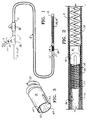
- Catheter apparatus 2 suitable for guiding the occlusive implant delivery assembly and providing actuation pressure for the hydraulically actuated release mechanism embodiments is shown.
- Catheter apparatus 2 generally includes a catheter 4, syringe 6 and sidearms (adapters) 8A and 8B.
- Catheter 4 generally comprises an elongate tubular member having proximal and distal end portions 10 and 12.
- the catheter is preferably between about 50-300 cm in length, and typically between about 60-200 cm in length.
- the catheter also is designed for accessing a vessel site at which, for example, vasoocclusion is desired.
- the vessel site may be within a small diameter vessel having 2-5 mm lumen diameter and accessible by way of a tortuous vessel path which may involve sharp vessel turns and multiple vessel branches.
- the catheter preferably has a small diameter, flexible construction with a lumen diameter of less than about 40 mil, and preferably between about 8-30 mil. Catheters of this type, which are typically used for accessing deep brain vascular sites, are commercially available.
- the elongated tubular member or catheter 4 is secured at its proximal end 10 to sidearm 8A, which is of conventional design for introducing fluids or apparatus into the catheter.
- Sidearm 8B which is otherwise essentially similar in construction to sidearm 8A, can include a tubular extension 14 that surrounds a portion of the pusher as shown in FIG. 1.
- Mandrel 54, 56 or 68 which extends through the pusher, as will be discussed below in connection with FIGS. 9-15, extends through one tube of sidearm 8B.
- the discharge tip of syringe 6, which is used in conjunction with the embodiments shown in FIGS. 2-11 is fluidly coupled to the other tube of sidearm 8B and, thus, the inner lumen of pusher 26 through which the aforementioned mandrels extend.
- Syringe 6 is of conventional construction and includes a cylindrical barrel 18 and a plunger 20 that is reciprocally mounted therein.
- a stopcock 22 preferably is provided in the discharge piece of the syringe for opening or closing the fluid connection between the syringe and pusher lumen.
- the stopcock can be provided in a connector (not shown) that couples the discharge piece of the syringe to sidearm 8B.
- Occlusive implant delivery assembly 24 generally comprises a pusher or elongated carrier member 26, a coil type occlusive implant 28 and a decoupling or release mechanism for releasing the implant from the assembly.
- coil 28 is shown in the drawings as a uniform diameter helical coil wire, it may have other configurations. It is important, however, that the coil be dimensioned to be able to be advanced through a catheter that is sized to access the desired site.
- the coil may be made of radiopaque, biocompatible metal such as platinum, gold, tungsten, stainless steel or alloys of these metals.
- the coil comprises platinum, gold, tungsten or alloys of these metals so that its location at the site may be readily viewed radiographically.
- the coils will typically be made of 0.05 to 0.15 mm diameter platinum wire that is wound to have an inner diameter of 0.15 to 0.96 mm with a minimum pitch (i.e., the windings are close or tight).
- the length of the wound wire i.e., the coil
- the coil will normally be in the range of 0.5 to 60 cm, and preferably 0.5 to 40 cm.
- the coil has a preferred length of about 0.5 to 20 cm.
- the coil can have any shape.
- it can be formed so that it takes an essentially linear configuration in which it may be advanced through the catheter and assume a randomly oriented configuration, such as helical, after it is released from the catheter and in a relaxed state as disclosed in U.S. Patent No. 4,994,069, which is hereby incorporated herein by reference.
- the delivery assembly shown in FIGS. 2-6 generally comprises a pusher or elongated carrier member 26, coil 28 and coupling 30.
- the pusher preferably has a tubular construction to provide a lumen for fluidly coupling a source of pressurized fluid, such as syringe 6, and an inflatable member utilized in decoupling the coil from the pusher, as will be described in more detail below.
- Pusher 26 also preferably has a proximal section that is rigid enough to facilitate torque transmission to the distal portion of the pusher.
- the distal section of the pusher may be constructed to be more flexible than the proximal portion to facilitate navigation of the distal section into very tiny vessels encountered in the brain, for example.
- proximal tubular section of pusher 26 (designated with reference numeral 32) is a metal tube, preferably a stainless steel tube, and the distal section of pusher 26, section 34, comprises a coil 36, which is wrapped in a flexible, elastomeric film 38 to fluidly seal the spaces between the coil windings. Film 38 also overlaps section 34 to seal the juncture between section 34 an coil 36. Film 38 can be in the form of shrinkwrap and, thus, applied to coil 36 and proximal section 34 with conventional shrinkwrap techniques. Coil 36 and, thus, distal coiled section 34 is secured to the proximal tubular section 32 by welding, soldering, brazing, or adhesive.
- the pusher comprises a rigid plastic tube which can be ground with a tapered distal section to achieve the desired flexibility.
- Suitable materials for this configuration include PEEK and polyimide.
- the inner diameter of the distal section in this configuration preferably is significantly less than the outer diameter of the proximal section to which the balloon can attached (e.g., glued).
- the lumen which provides for fluid flow between the source of pressurized fluid and the balloon, has a diameter of about 0.007 inch throughout its length and the distal section has an outer diameter of about 0.014 inch.
- the outer diameter of the proximal section depends on the application. For a 3 French catheter, the outer diameter of the proximal section may be about 0.016 to 0.018 inch.
- a conventional inflatable balloon 40 having a construction similar to those used in conventional balloon catheters, is secured to the distal end of coil 36 by adhesive, for example, such that a fluid tight path is formed between the interior of the balloon and the central lumen of pusher 26, which is formed by proximal and distal sections 32, 34 of pusher 26.
- balloon 40 extends into tube 42, which is also secured to implant coil 28 by welding, soldering, brazing or adhesive.
- coupling 30 comprises a tubular member or split tube having slots formed in the axial direction and which open into the end of the tube that is directly coupled to the distal portion of pusher coil 38.
- the tube to pusher coupling can be accomplished by a pressure fit, welding, soldering, brazing or adhesive.
- Slots 42 form multiple segments 44 in tubular coupling 30 and facilitate displacement of those segments to effect release of the coil implant from the pusher, as will be described in more detail below. Although a two slot configuration is shown, other multiples of slots can be used to facilitate displacement of the proximal portion of the coupling as well as other conventional jaw or latch clamping configurations.
- Tubular coupling 30 can be made from platinum, stainless steel or plastic that is biocompatible with the environment in which the coupling will be placed.
- the coupling 30 preferably also has a very thin wall of about 0.001 to 0.0003 inches.
- FIGS. 2-6 The implant delivery assembly of FIGS. 2-6 will be further described by way of the following operative example which is provided merely for exemplary purposes and is not intended to limit the invention to a particular application.
- catheter 4 may include a guidewire usable therewith to guide the distal end of the catheter toward the desired or selected occlusion site.
- Guidewires of this type are commercially available, and generally include an elongate wire having a tapered, wire-wound distal end region which is adapted to be advanced through a tortuous vessel path, with the catheter being moved axially along the advanced guidewire.
- the catheter is cleared. For example, if a guidewire has been used to position the catheter, it is withdrawn from within the catheter.
- the implant delivery assembly as shown in FIG. 2, is introduced into the proximal end portion of catheter 4, and advanced toward the distal end portion of catheter 4.
- the proximal end of pusher 26 is manipulated via sidearm 8B, to which it is attached, so that coupling 30 and coil implant 28 extend beyond the distal end of the catheter with coupling 30 free of the catheter and the coil positioned exactly at the desired site (FIG. 4).
- Stopcock 22 is then placed in an open position and the plunger of syringe 6 advanced to inflate balloon 40 as shown in FIG. 5.
- balloon 40 As balloon 40 is inflated, it further opens split tube or coupling 30, i.e., segments 44 are displaced radially outward to decouple coupling 30 and coil 28 from pusher 26 without transmitting any significant force to coil 28.
- the balloon is then deflated by retracting the plunger in syringe 6, thereby releasing coupling 30 from balloon 40 so that the pusher can be retracted without altering the position of coil 28.
- the catheter is withdrawn from the vessel.
- coupling 30' has its proximal portion fixedly secured to the distal end of coiled portion 34.
- coupling 30' includes end walls 48 at its distal end for overlapping end piece or cap 50 provided at the proximal end of coil implant 28'. That is the end walls, which generally form jaws, releasably secure coil 28' to coupling 30' and, thus, releasably secure coil 28' to pusher 26.
- Coupling 30' also differs from coupling 30 in that slots 42' are formed in the distal portion of the coupling.
- FIGS. 9-11 a further embodiment of the invention is shown.
- This embodiment essentially differs from those described above in that the release or decoupling mechanism simply comprises a balloon.
- the balloon extends from the pusher with its proximal portion close fit within coil 28.
- the balloon is inflated, and as the balloon expands, the coil slides off the end of the balloon as will be described in more detail below.
- the decoupling mechanism of FIGS. 9-11 comprises a balloon 40' having its open end secured to the distal coiled section 34 of pusher 26, for example, by adhesive.
- Balloon 40' is packed into the proximal portion of coil 28 such that the balloon frictionally engages the inner surface of coil 28 and secures the coil to the balloon.
- the balloon is constructed such that, when in the deflated state, the balloon has a plurality of circumferentially extending ribs 52, which preferably are configured to have a pitch corresponding to that of the coil so that the ribs can snugly fit between the windings of the coil.
- the ribs can be formed by placing a mandrel into the balloon, wrapping a thread around the balloon in the regions where the ribs are desired to be located, and then dipping the balloon, mandrel and thread assembly in a reservoir of elastomeric material, such as silicon, to form an outer ribbed elastomeric coating for the balloon.
- elastomeric material such as silicon
- the decoupling mechanism of the embodiment illustrated in FIGS. 9-11 also preferably includes a mandrel 54 which extends from outside sidearm 8B through catheter 12 via the interior lumen of pusher 26 and into balloon 40'.
- Mandrel 52 facilitates inserting balloon 40' within coil 28 and preferably is sized to force the outer wall of the balloon against the inner circumferential surface of coil 28 to enhance the interlocking connection between the coil and balloon.
- the pusher and the mandrel are advanced through catheter 4 until coil 28 is positioned at the desired location (FIG. 9).
- the mandrel is then retracted or withdrawn from the balloon and the syringe actuated to inflate the balloon 40' as described above (FIG. 10).
- mandrel 54 is sized so that when placed in the pusher lumen, sufficient space between the mandrel and the inner surface of the proximal and distal sections 32, 34 of pusher 26 is formed. In this manner, the interior of balloon 40' can be fluidly coupled to the syringe 6 when stopcock 22 is in the open position and the mandrel is in the pusher.
- the balloon inflates and stretches, the ribs generally flatten and the proximal end of coil 28 slides off the distal end portion of balloon 40'.
- the balloon can be retracted as it is inflated.
- the end of the balloon can be positioned where the proximal end of the coil is desired to be finally located.
- the proximal end of the coil will ultimately be located at the distal end of the balloon.
- the balloon position can be determined by conventional means such as radiographic techniques.
- the pusher can then be retracted as shown in FIG. 11 and the balloon deflated. The procedure is repeated if the delivery of additional coils is desired.
- the release or decoupling mechanism comprises a mechanically expandable or locking member rather than a fluidly inflatable/expandable balloon.
- the expandable locking member fits within the proximal end of the coil and is radially expanded to grip the inner circumferential surface of the coil. When the expandable member is returned to a generally relaxed state so that its diameter decreases, the coil is released.
- the decoupling mechanism shown in FIGS. 12 and 13 gemerally comprises core wire or actuating member 56 and an elastomeric ring or locking member 60, such as an O-ring, which is slidably mounted on core wire 56.
- Core wire or mandrel 56 includes a proximal locking portion 62, which preferably has a generally uniform diameter, and a distal tapered or unlocking portion. More specifically, the diameter of the core wire locking portion exceeds the inner diameter of the ring such that when the ring is positioned on the locking portion it expands against the inner circumferential surface of coil 28 and frictionally locks the coil thereto (FIG. 12).
- the tapered portion tapers to a diameter that allows the ring to radially contract and release the coil.
- the tapered portion tapers to a diameter that is less than or equal to the inner diameter of the ring when the ring is in its relaxed state.
- Core wire 56 can be ground to the desired shape as is conventional in the art.
- actuating member 56 includes a stop member 66 to ensure that the elastomeric ring 60 does not become detached from the actuating member. Otherwise the ring would become free to migrate in the blood stream, which could result in an embolism.
- a disc 58 optionally may be secured to the distal end of coil 36 by welding, soldering, brazing or adhesive to simplify retraction of the pusher as will be discussed in more detail below.
- ring 60 is positioned on the locking portion of core wire 56 between the core wire and coil 28. Then, the pusher and core wire are both advanced through catheter 4 so that coil 28 eventually extends beyond the catheter and is positioned at the desired location (FIG. 12). Once coil 28 is so positioned, core wire 56 is slowly retracted, causing the tapered distal portion 54 to slide within the opening of ring 60, thereby allowing the ring to return to its relaxed, unexpanded state. In this state, the ring diameter is significantly less than the inner diameter of coil 28 to facilitate rapid coil release.
- stop member 66 which has a larger diameter than the inner diameter of ring 60, catches the ring and carries it as the core wire is completely withdrawn from coil 28 (FIG. 13).
- the entire pusher 26 can be withdrawn by merely retracting actuating member 56 as stop member 66 acts on coil 36 through ring 60 and disc 58 as is apparent from the drawings.
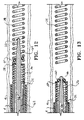
- the decoupling mechanism illustrated in these figures generally comprises a core wire or actuating member 68, disc or retaining member 70 and sleeve or locking member 72.
- Sleeve 72 is compressed to expand it in the radial direction and interlock the coil to the pusher assembly (FIG. 14). Once in place, it is extended to release the coil therefrom (FIG. 15).
- Core wire 68 extends from sidearm 8B as shown in Fig. 1.
- the distal end portion of core wire 68 preferably is secured to the distal end of sleeve 72 so that when the core wire 68 is retracted, sleeve 72 is compressed in the axial direction against disc 70 as shown in FIG. 14.
- Sleeve 72 preferably is of a material that, upon compression in the axial direction, will expand radially to interlock with coil 28. Accordingly, sleeve 72 can comprise fabric and, preferably, comprises braided material in which the degree of radial expansion generally depends upon the pitch of the braiding.
- the actuator is initially positioned as shown in FIG. 14 with the open end of sleeve 72 compressed against disc 70.
- the coil is released from the pusher assembly by simply advancing the core wire 68 as shown in FIG. 15 while maintaining pusher 26 is a fixed position. Then, pusher 26 and core wire 68 are concurrently retracted so as to maintain sleeve 72 in its extended position, while withdrawing sleeve 72 from coil 28 without placing any significant mechanical force on the coil in either the radial or axial direction.
Abstract
Description
- The present invention generally relates to surgical instruments. More particularly, the invention relates to delivery assemblies for delivering an occlusive device, such as an embolic coil, to a selected site within a mammal using an expandable coupling or decoupling mechanism.
- The endovascular treatment of a variety of vascular maladies throughout the body is an increasingly more important form of therapy. Catheters have been used to place various treatment materials, devices, and drugs within arteries and veins in the human body. Examples of these devices and their use in such treatments are shown in U.S. Patent Nos. 5,234,437 and 5,261,916, in which methods and devices for delivery of coils or wires within the human body to sites, such as aneurysms, to occlude those sites are disclosed. Coils, such as those discussed in these documents as well as in U.S. Patent No. 4,994,069, may be of a regular or helical configuration or assume a random convoluted configuration at the site. The coils normally are made of a radiopaque, biocompatible metal such as platinum, gold, tungsten or alloys of these and other metals. In treating aneurysms, it is common to place a number of coils within the aneurysm. The coils occlude the site by posing a physical barrier to blood flow and by promoting thrombus formation at the site.
- Coils have typically been placed at the desired site within the vasculature using a catheter and a pusher. The site is first accessed by the catheter. In treating peripheral or neural conditions requiring occlusion, the sites are accessed with flexible, small diameter catheters such as those shown in U.S. Patent Nos. 4,739,768 and 4,813,934. The catheter may be guided to the site through the use of guidewires (see U.S. Patent No. 4,884,579) or by flow-directed means such as balloons placed at the distal end of the catheter. Use of guidewires involves the placement of relatively long, torqueable proximal wire sections within the catheter attached to more flexible distal end wire sections designed to be advanced across sharp bends at vessel junctions. The guidewire is visible using x-ray techniques and allows a catheter to be navigated through extremely tortuous vessels, even those surrounded by soft tissue such as the brain.
- Once the site has been reached, the catheter lumen is cleared by removing the guidewire (if a guidewire has been used), and one or more coils are placed into the proximal open end of the catheter and advanced through the catheter with a pusher. Pushers are wires having distal ends adapted to engage and push the coil through the catheter lumen as a pusher itself is advanced through the catheter. Once the coil reaches the distal end of the catheter, it is discharged from the catheter by the pusher into the vascular site. However, there are concerns when discharging the coil from the distal end of the catheter. For example, the plunging action of the pusher and the coil can make it difficult to position the coil at the site in a controlled manner and with a fine degree of accuracy. Inaccurate placement of the coil can be problematic because once the coil has left the catheter, it is difficult to reposition or retrieve the coil.
- Several techniques involving Interlocking Detachable Coils (IDCs), which incorporate mechanical release mechanisms and Guglielmi Detachable Coils (GDCs), which utilize electrolytically actuated release mechanisms, have been developed to enable more accurate placement of coils within a vessel.
- One technique for detaching an embolic coil is shown in U.S. Patent No. 5,261,916. According to that technique, a coil having an enlarged portion is mated with a pusher having a keyway adapted to receive the enlarged portion of the coil in an interlocking relationship. The joint between the pusher and the coil is covered by a coaxial member. The coaxial member is movable by sliding the member axially. As the coaxial member is moved away from the junction where the coil's member engages the keyway of the pusher, the coil is freed from the catheter assembly and the pusher may then be removed.
- Another IDC device for placement of coils is shown in U.S. Patent No. 5,234,437. This device includes a coil having a helical portion at least one end and a pusher wire having a distal end that is threaded inside on the helical coil by use of a threaded section on the outside of the pusher. The device operates by engaging the proximal end of the coil with a sleeve and unthreading the pusher from the coil. Once the pusher is free, the sleeve may be used to push the coil out into the targeted treatment area.
- U.S. Patent No. 5,312,415 discloses the use of a catheter having a constricted or feathered end to retain a number of embolic coils on a guidewire for precise placement using a pusher sheath.
- Electrolytic coil detachment is disclosed in U.S. Patent Nos. 5,122,136 and 5,354,295. As disclosed in U.S. Patent No. 5,122,136, the coil is bonded via a metal-to-metal joint to the distal end of the pusher. The pusher and coil are made of dissimilar metals. The coil-carrying pusher is advanced through the catheter to the site and a small electrical current is passed through the pusher-coil assembly. The current causes the joint between the pusher and the coil to be severed via electrolysis. The pusher may then be retracted leaving the detached coil at an exact position within the vessel. Since no significant mechanical force is applied to the coil during electrolytic detachment, highly accurate coil placement is readily achieved. In addition, the electric current may facilitate thrombus formation at the coil site. The only perceived disadvantage of this method is that the electrolytic release of the coil may require a period of time that may inhibit rapid detachment of the coil from the pusher.
- Another method of placing an embolic coil is disclosed in U.S. Patent No. 5,108,407. This patent shows the use of a device in which embolic coils are separated from the distal end of a catheter by the use of heat-releasable adhesive bonds. The coil adheres to the therapeutic device via a mounting connection having a heat sensitive adhesive. Laser energy is transferred through a fiber optic cable which terminates at that connector. The connector becomes warm and releases the adhesive bond between the connector and the coil. Among the drawbacks of this system is that it involves generally complicated laser optic componentry.
- There is a need to provide alternative mechanical mechanisms for delivering implants, such as embolic coils, that combine accurate positioning capability with rapid implant decoupling response times.
- The present invention provides a mechanical occlusive implant delivery assembly having a rapid response decoupling or detachment mechanism that does not effect significant migration of the implant during release. The assembly includes an occlusive implant device, such as an embolic coil, a pusher or device to carry the implant to the selected location, and an expandable mechanism that is expanded or contracted to release the implant at the selected site. The invention advantageously incorporates a release mechanism that simply involves unloading a locking force, which is preferably uniformly applied, thereby avoiding the transmission of any significant force to the implant during release. In addition, the locking members preferably have generally, smooth, rounded configurations so that they do not catch and dislodge previously positioned coils upon retraction.
- According to a first embodiment of the invention, the occlusive implant delivery assembly includes an occlusive implant; a pusher having a proximal section and a distal section; a coupling having first and second portions, the first portion being coupled to the distal section of the pusher and the second portion being coupled to the implant; and an inflatable member having a proximal portion and a distal portion, the proximal portion being coupled to the distal section of the pusher. At least a portion of the inflatable member is disposed in the coupling such that when inflated, it expands the coupling and decouples the coupling from either the implant or the pusher. With this arrangement, rapid implant release times can be achieved with minimal, if any, force being applied to the implant. That is, the hydraulic pressure is only transmitted to the detachment point or juncture between the inflatable member and the implant, and not to the implant.
- According to another aspect of this embodiment, the inflatable member and coupling are configured so that the hydraulic pressure generated by the inflatable member is applied uniformly to the inner circumferential surface of the coupling. Thus, any force that may be applied to the implant in the radial direction is countered by an equal, but opposite force, thereby avoiding implant displacement during release. In the preferred embodiment, the coupling is cylindrical with an essentially uniform radius and the inflatable member is essentially symmetrical about its longitudinal axis in the inflated and uninflated states.
- According to another embodiment of the invention the implant delivery assembly comprises an occlusive implant having a tubular portion; a pusher having a proximal section and a distal section; and an inflatable member having a first portion coupled to the distal section of the pusher and a second portion disposed in the tubular portion of the implant such that upon inflation of the inflatable member the implant and member tend to separate. More specifically, the coil slides off of the inflatable member. In addition to causing minimal post delivery migration of the implant, this construction provides an advantageously simple one-piece decoupling mechanism, which can be readily manufactured.
- According to another aspect of this embodiment, the inflatable member and tubular portion also are configured as described above so that the hydraulic pressure generated by the inflatable member is applied uniformly to the inner circumferential surface of the tubular portion. In the preferred embodiment, the inner surface of the tubular portion is essentially symmetrical about its longitudinal axis and the inflatable member is essentially symmetrical about its longitudinal axis when inflated or deflated to provide an essentially uniformly distributed force to the inner circumference of the tubular section.
- According to yet a further embodiment of the invention, the implant delivery assembly comprises an occlusive implant having a tubular portion; a pusher having a proximal section and a distal section; a core member slidably disposed within the pusher and extending into the tubular portion; and a locking member releasably coupled to the coil and core member. With this construction the release mechanism is simply mechanically expanded to interlock the implant to the pusher and relaxed to release the implant.
- In a first configuration, the locking member comprises an elastomeric ring, such as an O-ring, and the core member includes a locking portion and a tapered portion adjacent thereto. The diameter of the core member exceeds the inner diameter of the ring such that when the ring is positioned on the locking portion it expands and frictionally locks the tubular portion thereto. On the other hand, the tapered portion tapers to a diameter that allows the ring to contract. In the preferred embodiment, the tapered portion is less than or equal to the inner diameter of the ring when the ring is in its relaxed state. When the core member is retracted, the tapered portion becomes positioned within the ring and allows the ring to radially contract and release the tubular portion and, thus, the implant, as the locking member returns to its relaxed state.
- In another configuration, the locking member comprises a flexible sleeve and the core member extends into the sleeve and is secured thereto. The sleeve is configured so that when axially compressed, it expands radially against the inner surface of the tubular portion and frictionally locks the implant thereto. The core member is retracted to compress the sleeve against a restraint, expand it radially and lock the implant to the delivery assembly. When it is desired to release the implant, the core member is advanced to remove the axial compression and radially contract the sleeve.
- These configurations advantageously eliminate the need for auxiliary hydraulics.
- The invention will be further described by way of example, with reference to the accompanying drawings, in which:-
- FIG. 1 shows a catheter apparatus constructed according to a general embodiment of the present invention;
- FIG. 2 is an enlarged, fragmentary view of an occlusive implant delivery assembly, constructed according to the principles of the present invention, disposed within a catheter;
- FIG. 3 is a perspective view of the coupling mechanism that forms part of the release mechanism shown in FIG. 2;
- FIG. 4 is an enlarged, fragmentary view of the implant delivery assembly of FIG. 2 with the implant positioned at a desired location;
- FIG. 5 is a further view of the implant delivery assembly shown in FIG. 4 with the coupling of the release mechanism expanded to unlock and release the implant from the pusher;
- FIG. 6 shows the release mechanism deflated and retracted from the implant location;
- FIG. 7 is an enlarged, fragmentary view of another embodiment of the implant delivery system of the present invention with the release mechanism in a locked state;
- FIG. 8 illustrates the release mechanism of FIG. 7 in an unlocked state;
- FIG. 9 is a further embodiment of the release mechanism of the present invention;
- FIG. 10 is a further view of the release mechanism shown in FIG. 9 showing the mechanism actuated to release the coil therefrom;
- FIG. 11 is a further view of the release mechanism shown in FIGS. 8 and 9 illustrating the implant fully detached from the mechanism;
- FIG. 12 is an enlarged, fragmentary view of yet another embodiment of the release mechanism of the present invention showing the mechanism in a locked state;
- FIG. 13 is a further view of the release mechanism of FIG. 12 illustrating the mechanism in an unlocked configuration;
- FIG. 14 is yet a further embodiment of the release mechanism of the present invention illustrating the mechanism in a locked configuration; and
- FIG. 15 is a further view of the release mechanism of FIG. 14 showing the mechanism in an unlocked configuration and the implant released therefrom.
- Referring to the drawings in detail, wherein like numerals indicate like elements, several embodiments of an occlusive implant delivery assembly are shown according to the principles of the present invention. The various embodiments employ an expandable mechanism, which is expanded or contracted, to decouple and release the implant at the desired site. Although variously configured implants can be used in conjunction with the assembly of the present invention, an embolic coil type implant will be described for purposes of example.
- The operation of the assembly generally comprises the steps of (1) advancing a catheter through a vessel lumen, for example, to the vicinity of the site to be occluded (e.g., an aneurysm, vascular malformation, or arterial venous fistula), (2) advancing the implant delivery assembly through and beyond the catheter to the location, and (3) radially expanding or contracting the release mechanism to detach the implant from the assembly.
- Referring to FIG. 1, a catheter apparatus 2 suitable for guiding the occlusive implant delivery assembly and providing actuation pressure for the hydraulically actuated release mechanism embodiments is shown. Catheter apparatus 2 generally includes a
catheter 4, syringe 6 and sidearms (adapters) 8A and 8B.Catheter 4 generally comprises an elongate tubular member having proximal anddistal end portions - The elongated tubular member or
catheter 4 is secured at itsproximal end 10 to sidearm 8A, which is of conventional design for introducing fluids or apparatus into the catheter. The end ofproximal section 32 ofpusher 26, which will be described in more detail below, extends throughsidearm 8A and is coupled to the distal or downstream end ofsidearm 8B. Sidearm 8B, which is otherwise essentially similar in construction to sidearm 8A, can include a tubular extension 14 that surrounds a portion of the pusher as shown in FIG. 1.Mandrel sidearm 8B. The discharge tip of syringe 6, which is used in conjunction with the embodiments shown in FIGS. 2-11 is fluidly coupled to the other tube ofsidearm 8B and, thus, the inner lumen ofpusher 26 through which the aforementioned mandrels extend. - Syringe 6 is of conventional construction and includes a cylindrical barrel 18 and a
plunger 20 that is reciprocally mounted therein. A stopcock 22 preferably is provided in the discharge piece of the syringe for opening or closing the fluid connection between the syringe and pusher lumen. Alternatively, the stopcock can be provided in a connector (not shown) that couples the discharge piece of the syringe tosidearm 8B. When the stopcock is in the closed position, the decoupling or release mechanism of the implant delivery assembly will not be inadvertently actuated, thereby avoiding wrongly positioning the implant within the body as a result of such accidental discharge of liquid from the syringe into the catheter. - As discussed above, the implant delivery assembly, which is generally designated with
reference numeral 24 in FIG. 1, is guided throughcatheter 4 towards the intended vasoocclusion site. Occlusiveimplant delivery assembly 24 generally comprises a pusher orelongated carrier member 26, a coiltype occlusive implant 28 and a decoupling or release mechanism for releasing the implant from the assembly. Althoughcoil 28 is shown in the drawings as a uniform diameter helical coil wire, it may have other configurations. It is important, however, that the coil be dimensioned to be able to be advanced through a catheter that is sized to access the desired site. The coil may be made of radiopaque, biocompatible metal such as platinum, gold, tungsten, stainless steel or alloys of these metals. Preferably, the coil comprises platinum, gold, tungsten or alloys of these metals so that its location at the site may be readily viewed radiographically. - For use in occluding peripheral or neural sites, the coils will typically be made of 0.05 to 0.15 mm diameter platinum wire that is wound to have an inner diameter of 0.15 to 0.96 mm with a minimum pitch (i.e., the windings are close or tight). The length of the wound wire (i.e., the coil) will normally be in the range of 0.5 to 60 cm, and preferably 0.5 to 40 cm. For wires intended for use in vessels with diameters of about 2 mm and smaller, the coil has a preferred length of about 0.5 to 20 cm. The coil can have any shape. For example, it can be formed so that it takes an essentially linear configuration in which it may be advanced through the catheter and assume a randomly oriented configuration, such as helical, after it is released from the catheter and in a relaxed state as disclosed in U.S. Patent No. 4,994,069, which is hereby incorporated herein by reference.
- Referring to FIGS. 2-6, a first embodiment of the occlusive implant delivery assembly, will be described. The delivery assembly shown in FIGS. 2-6 generally comprises a pusher or
elongated carrier member 26,coil 28 and coupling 30. The pusher preferably has a tubular construction to provide a lumen for fluidly coupling a source of pressurized fluid, such as syringe 6, and an inflatable member utilized in decoupling the coil from the pusher, as will be described in more detail below.Pusher 26 also preferably has a proximal section that is rigid enough to facilitate torque transmission to the distal portion of the pusher. The distal section of the pusher may be constructed to be more flexible than the proximal portion to facilitate navigation of the distal section into very tiny vessels encountered in the brain, for example. - In the preferred embodiment, proximal tubular section of pusher 26 (designated with reference numeral 32) is a metal tube, preferably a stainless steel tube, and the distal section of
pusher 26,section 34, comprises acoil 36, which is wrapped in a flexible,elastomeric film 38 to fluidly seal the spaces between the coil windings.Film 38 also overlapssection 34 to seal the juncture betweensection 34 ancoil 36.Film 38 can be in the form of shrinkwrap and, thus, applied tocoil 36 andproximal section 34 with conventional shrinkwrap techniques.Coil 36 and, thus, distalcoiled section 34 is secured to the proximaltubular section 32 by welding, soldering, brazing, or adhesive. - Alternatively, a more simple pusher configuration may be used in which the pusher comprises a rigid plastic tube which can be ground with a tapered distal section to achieve the desired flexibility. Suitable materials for this configuration include PEEK and polyimide. The inner diameter of the distal section in this configuration preferably is significantly less than the outer diameter of the proximal section to which the balloon can attached (e.g., glued). In a preferred embodiment, the lumen, which provides for fluid flow between the source of pressurized fluid and the balloon, has a diameter of about 0.007 inch throughout its length and the distal section has an outer diameter of about 0.014 inch. The outer diameter of the proximal section depends on the application. For a 3 French catheter, the outer diameter of the proximal section may be about 0.016 to 0.018 inch. Although particular pusher configurations have been described, it should be understood that other configurations may be used without departing from the scope of the invention.
- A conventional
inflatable balloon 40, having a construction similar to those used in conventional balloon catheters, is secured to the distal end ofcoil 36 by adhesive, for example, such that a fluid tight path is formed between the interior of the balloon and the central lumen ofpusher 26, which is formed by proximal anddistal sections pusher 26. - Returning to FIG. 2,
balloon 40 extends intotube 42, which is also secured to implantcoil 28 by welding, soldering, brazing or adhesive. As shown in FIG. 2, coupling 30 comprises a tubular member or split tube having slots formed in the axial direction and which open into the end of the tube that is directly coupled to the distal portion ofpusher coil 38. The tube to pusher coupling can be accomplished by a pressure fit, welding, soldering, brazing or adhesive.Slots 42 formmultiple segments 44 in tubular coupling 30 and facilitate displacement of those segments to effect release of the coil implant from the pusher, as will be described in more detail below. Although a two slot configuration is shown, other multiples of slots can be used to facilitate displacement of the proximal portion of the coupling as well as other conventional jaw or latch clamping configurations. - Tubular coupling 30 can be made from platinum, stainless steel or plastic that is biocompatible with the environment in which the coupling will be placed. The coupling 30 preferably also has a very thin wall of about 0.001 to 0.0003 inches.
- The implant delivery assembly of FIGS. 2-6 will be further described by way of the following operative example which is provided merely for exemplary purposes and is not intended to limit the invention to a particular application.
- A catheter is inserted through the vessel lumen to the site to be occluded (e.g., an aneurysm, vascular malformation, or arteriovenous fistula. Conventional catheter insertion and navigational procedures involving guidewire and/or flow-directed means may be used to access the site with the catheter. Thus, although not shown,
catheter 4 may include a guidewire usable therewith to guide the distal end of the catheter toward the desired or selected occlusion site. Guidewires of this type are commercially available, and generally include an elongate wire having a tapered, wire-wound distal end region which is adapted to be advanced through a tortuous vessel path, with the catheter being moved axially along the advanced guidewire. - Once the distal end of the catheter is positioned at the selected site (its location may be determined by a coating at the distal end of the catheter with a radiopaque material or otherwise affixing such a material to the distal end of the catheter or incorporating such a material into the distal end of the catheter), the catheter is cleared. For example, if a guidewire has been used to position the catheter, it is withdrawn from within the catheter.
- Then, the implant delivery assembly, as shown in FIG. 2, is introduced into the proximal end portion of
catheter 4, and advanced toward the distal end portion ofcatheter 4. The proximal end ofpusher 26 is manipulated viasidearm 8B, to which it is attached, so that coupling 30 andcoil implant 28 extend beyond the distal end of the catheter with coupling 30 free of the catheter and the coil positioned exactly at the desired site (FIG. 4).Stopcock 22 is then placed in an open position and the plunger of syringe 6 advanced to inflateballoon 40 as shown in FIG. 5. Asballoon 40 is inflated, it further opens split tube or coupling 30, i.e.,segments 44 are displaced radially outward to decouple coupling 30 andcoil 28 frompusher 26 without transmitting any significant force tocoil 28. The balloon is then deflated by retracting the plunger in syringe 6, thereby releasing coupling 30 fromballoon 40 so that the pusher can be retracted without altering the position ofcoil 28. After the desired number of coils have been placed at the site, the catheter is withdrawn from the vessel. - Referring to FIGS. 7 and 8, a further embodiment of the release or decoupling mechanism is shown similar to that shown in FIGS. 2-6, but in which coupling 30' has its proximal portion fixedly secured to the distal end of coiled
portion 34. In addition, coupling 30' includesend walls 48 at its distal end for overlapping end piece or cap 50 provided at the proximal end of coil implant 28'. That is the end walls, which generally form jaws, releasably secure coil 28' to coupling 30' and, thus, releasably secure coil 28' topusher 26. Coupling 30' also differs from coupling 30 in that slots 42' are formed in the distal portion of the coupling. Once the coil implant is positioned at the desired location, fluid is introduced through the hollow pusher member and intoballoon 40, as described above, to displace segments 44' radially outward and release coil 28' from coupling 30' (FIG. 8). The balloon can then be deflated and the pusher retracted. With this configuration, the coupling is advantageously withdrawn with the pusher. - Referring to FIGS. 9-11, a further embodiment of the invention is shown. This embodiment essentially differs from those described above in that the release or decoupling mechanism simply comprises a balloon. The balloon extends from the pusher with its proximal portion close fit within
coil 28. When it is desired to deploy the coil, the balloon is inflated, and as the balloon expands, the coil slides off the end of the balloon as will be described in more detail below. - The decoupling mechanism of FIGS. 9-11 comprises a balloon 40' having its open end secured to the distal
coiled section 34 ofpusher 26, for example, by adhesive. Balloon 40' is packed into the proximal portion ofcoil 28 such that the balloon frictionally engages the inner surface ofcoil 28 and secures the coil to the balloon. To enhance the securement between the coil and balloon, the balloon is constructed such that, when in the deflated state, the balloon has a plurality of circumferentially extendingribs 52, which preferably are configured to have a pitch corresponding to that of the coil so that the ribs can snugly fit between the windings of the coil. The ribs can be formed by placing a mandrel into the balloon, wrapping a thread around the balloon in the regions where the ribs are desired to be located, and then dipping the balloon, mandrel and thread assembly in a reservoir of elastomeric material, such as silicon, to form an outer ribbed elastomeric coating for the balloon. - The decoupling mechanism of the embodiment illustrated in FIGS. 9-11 also preferably includes a
mandrel 54 which extends fromoutside sidearm 8B throughcatheter 12 via the interior lumen ofpusher 26 and into balloon 40'.Mandrel 52 facilitates inserting balloon 40' withincoil 28 and preferably is sized to force the outer wall of the balloon against the inner circumferential surface ofcoil 28 to enhance the interlocking connection between the coil and balloon. - In operation, the pusher and the mandrel are advanced through
catheter 4 untilcoil 28 is positioned at the desired location (FIG. 9). The mandrel is then retracted or withdrawn from the balloon and the syringe actuated to inflate the balloon 40' as described above (FIG. 10). In this case, it is important thatmandrel 54 is sized so that when placed in the pusher lumen, sufficient space between the mandrel and the inner surface of the proximal anddistal sections pusher 26 is formed. In this manner, the interior of balloon 40' can be fluidly coupled to the syringe 6 whenstopcock 22 is in the open position and the mandrel is in the pusher. As the balloon inflates and stretches, the ribs generally flatten and the proximal end ofcoil 28 slides off the distal end portion of balloon 40'. In order to avoid axial displacement of the coil, the balloon can be retracted as it is inflated. Alternatively, the end of the balloon can be positioned where the proximal end of the coil is desired to be finally located. As the balloon inflates, the proximal end of the coil will ultimately be located at the distal end of the balloon. The balloon position can be determined by conventional means such as radiographic techniques. The pusher can then be retracted as shown in FIG. 11 and the balloon deflated. The procedure is repeated if the delivery of additional coils is desired. - Referring to FIGS. 12-15, further embodiments of the invention are shown in which the release or decoupling mechanism comprises a mechanically expandable or locking member rather than a fluidly inflatable/expandable balloon. The expandable locking member fits within the proximal end of the coil and is radially expanded to grip the inner circumferential surface of the coil. When the expandable member is returned to a generally relaxed state so that its diameter decreases, the coil is released.
- The decoupling mechanism shown in FIGS. 12 and 13 gemerally comprises core wire or actuating member 56 and an elastomeric ring or locking
member 60, such as an O-ring, which is slidably mounted on core wire 56. Core wire or mandrel 56 includes aproximal locking portion 62, which preferably has a generally uniform diameter, and a distal tapered or unlocking portion. More specifically, the diameter of the core wire locking portion exceeds the inner diameter of the ring such that when the ring is positioned on the locking portion it expands against the inner circumferential surface ofcoil 28 and frictionally locks the coil thereto (FIG. 12). On the other hand, the tapered portion tapers to a diameter that allows the ring to radially contract and release the coil. In the preferred embodiment, the tapered portion tapers to a diameter that is less than or equal to the inner diameter of the ring when the ring is in its relaxed state. When the core wire is retracted, the tapered portion becomes positioned within the ring and allows the ring to radially contract and release the coil as it returns to its relaxed state (FIG. 13). Core wire 56 can be ground to the desired shape as is conventional in the art. - In addition, the distal portion of actuating member 56 includes a
stop member 66 to ensure that theelastomeric ring 60 does not become detached from the actuating member. Otherwise the ring would become free to migrate in the blood stream, which could result in an embolism. Adisc 58 optionally may be secured to the distal end ofcoil 36 by welding, soldering, brazing or adhesive to simplify retraction of the pusher as will be discussed in more detail below. - In operation,
ring 60 is positioned on the locking portion of core wire 56 between the core wire andcoil 28. Then, the pusher and core wire are both advanced throughcatheter 4 so thatcoil 28 eventually extends beyond the catheter and is positioned at the desired location (FIG. 12). Oncecoil 28 is so positioned, core wire 56 is slowly retracted, causing the tapereddistal portion 54 to slide within the opening ofring 60, thereby allowing the ring to return to its relaxed, unexpanded state. In this state, the ring diameter is significantly less than the inner diameter ofcoil 28 to facilitate rapid coil release. As the core wire is further retracted,stop member 66, which has a larger diameter than the inner diameter ofring 60, catches the ring and carries it as the core wire is completely withdrawn from coil 28 (FIG. 13). Whendisc 58 is incorporated, theentire pusher 26 can be withdrawn by merely retracting actuating member 56 asstop member 66 acts oncoil 36 throughring 60 anddisc 58 as is apparent from the drawings. - Referring to FIGS. 14 and 15, a further embodiment of the release or decoupling mechanism is shown. The decoupling mechanism illustrated in these figures generally comprises a core wire or actuating
member 68, disc or retainingmember 70 and sleeve or lockingmember 72.Sleeve 72 is compressed to expand it in the radial direction and interlock the coil to the pusher assembly (FIG. 14). Once in place, it is extended to release the coil therefrom (FIG. 15). -
Core wire 68 extends fromsidearm 8B as shown in Fig. 1. The distal end portion ofcore wire 68, preferably is secured to the distal end ofsleeve 72 so that when thecore wire 68 is retracted,sleeve 72 is compressed in the axial direction againstdisc 70 as shown in FIG. 14.Sleeve 72 preferably is of a material that, upon compression in the axial direction, will expand radially to interlock withcoil 28. Accordingly,sleeve 72 can comprise fabric and, preferably, comprises braided material in which the degree of radial expansion generally depends upon the pitch of the braiding. - The actuator is initially positioned as shown in FIG. 14 with the open end of
sleeve 72 compressed againstdisc 70. The coil is released from the pusher assembly by simply advancing thecore wire 68 as shown in FIG. 15 while maintainingpusher 26 is a fixed position. Then,pusher 26 andcore wire 68 are concurrently retracted so as to maintainsleeve 72 in its extended position, while withdrawingsleeve 72 fromcoil 28 without placing any significant mechanical force on the coil in either the radial or axial direction. - The above is a detailed description of several embodiments of the invention. It is recognized that departures from the disclosed embodiments may be made within the scope of the invention and that obvious modifications will occur to a person skilled in the art. The full scope of the invention is set out in the claims that follow and their equivalents. Accordingly, the claims and specification should not be construed to unduly narrow the full scope of protection to which the invention is entitled.
Claims (17)
- An occlusive implant delivery assembly for occluding a site in a mammal, said assembly comprising:
an occlusive implant;
a pusher having a proximal section and a distal section;
a coupling having first and second portions, said first portion being coupled to said distal section of the pusher and said second portion being coupled to said implant;
an inflatable member having a proximal portion and a distal portion, said proximal portion being coupled to said distal section of the pusher, at least a portion of said inflatable member being disposed in said coupling such that when inflated, it expands the coupling and decouples the coupling from one of the implant and the pusher. - The assembly of claim 1, wherein said coupling is a split tube having slots formed therein in the axial direction.
- The assembly of claim 1 or 2, wherein said coupling includes segments spaced from one another in the circumferential direction, said segments being detachably coupled to said pusher.
- The assembly of claim 1 or 2, wherein said coupling includes segments spaced from one another in the circumferential direction, said segments being detachably coupled to said coil.
- An occlusive implant delivery assembly for occluding a site in a mammal, said assembly comprising:
an occlusive implant having a tubular portion;
a pusher having a proximal section and a distal section;
an inflatable member having a first portion coupled to said distal section of the pusher and a second portion frictionally held in said tubular portion when deflated such that upon inflation of said inflatable member said implant and member tend to separate. - The assembly of claim 5, wherein said second portion of said inflatable member has a tapered configuration when said inflatable member is inflated.
- The assembly of claim 5 or 6, wherein said inflatable member has a plurality of ribs that extend radially outward and engage said tubular portion when said inflatable member is deflated.
- The assembly of claim 7, wherein said ribs further extend in a circumferential direction.
- The assembly of claim 8, wherein said implant comprises a coil having multiple turns and selected ones of said ribs extend between selected ones of said turns.
- The assembly of claim 9, further including a core member that extends within said pusher and into said inflatable member, said core member being sized to urge said inflatable member against said tubular portion.
- The assembly of any one of claims 5 to 10, further including a core member that extends within said pusher and into said inflatable member, said core member being sized to urge said inflatable member against said tubular portion.
- An occlusive implant delivery assembly for occluding a site in a mammal, said assembly comprising:
an occlusive implant having a tubular portion;
a pusher having a proximal section and a distal section;
a core member slidably disposed within said pusher and extending into said tubular portion; and
a locking member being releasably coupled to said coil and said core member. - The assembly of claim 12, wherein said locking member comprises an elastomeric ring and said core member extends into said ring, said core member including a locking portion and a tapered portion, said locking portion having a diameter that exceeds the inner diameter of the ring when the ring is in a relaxed state, said tapered portion tapers to an outer diameter that is less than that of said locking portion.
- The assembly of claim 13, wherein said core member has a proximal end portion, a distal end portion, and a stop member positioned along said distal end portion, said proximal end portion having a diameter greater than the inner diameter of said ring when in a relaxed state.
- The assembly of claim 12, wherein said locking member comprises a flexible sleeve, and said core member extends into said sleeve and is secured thereto, said sleeve being configured so that when axially compressed, it expands radially against the inner surface of the tubular portion.
- The assembly of any one of the preceding claims, wherein said implant is coil.
- The assembly of any one of the preceding claims, wherein the pusher includes a passage formed therethrough and said inflatable member has an inlet, said passage being fluidly coupled to said inlet.
Priority Applications (2)
| Application Number | Priority Date | Filing Date | Title |
|---|---|---|---|
| EP02027844A EP1290988B1 (en) | 1994-12-22 | 1995-12-19 | Implant delivery assembly with expandable coupling/decoupling mechanism |
| EP05004642A EP1537838B1 (en) | 1994-12-22 | 1995-12-19 | Implant delivery assembly with coupling/decoupling mechanism |
Applications Claiming Priority (2)
| Application Number | Priority Date | Filing Date | Title |
|---|---|---|---|
| US08/363,264 US5814062A (en) | 1994-12-22 | 1994-12-22 | Implant delivery assembly with expandable coupling/decoupling mechanism |
| US363264 | 1994-12-22 |
Related Child Applications (1)
| Application Number | Title | Priority Date | Filing Date |
|---|---|---|---|
| EP02027844A Division EP1290988B1 (en) | 1994-12-22 | 1995-12-19 | Implant delivery assembly with expandable coupling/decoupling mechanism |
Publications (2)
| Publication Number | Publication Date |
|---|---|
| EP0717969A2 true EP0717969A2 (en) | 1996-06-26 |
| EP0717969A3 EP0717969A3 (en) | 1996-11-27 |
Family
ID=23429526
Family Applications (3)
| Application Number | Title | Priority Date | Filing Date |
|---|---|---|---|
| EP02027844A Expired - Lifetime EP1290988B1 (en) | 1994-12-22 | 1995-12-19 | Implant delivery assembly with expandable coupling/decoupling mechanism |
| EP95309242A Withdrawn EP0717969A3 (en) | 1994-12-22 | 1995-12-19 | Implant delivery assembly with expandable coupling/decoupling mechanism |
| EP05004642A Expired - Lifetime EP1537838B1 (en) | 1994-12-22 | 1995-12-19 | Implant delivery assembly with coupling/decoupling mechanism |
Family Applications Before (1)
| Application Number | Title | Priority Date | Filing Date |
|---|---|---|---|
| EP02027844A Expired - Lifetime EP1290988B1 (en) | 1994-12-22 | 1995-12-19 | Implant delivery assembly with expandable coupling/decoupling mechanism |
Family Applications After (1)
| Application Number | Title | Priority Date | Filing Date |
|---|---|---|---|
| EP05004642A Expired - Lifetime EP1537838B1 (en) | 1994-12-22 | 1995-12-19 | Implant delivery assembly with coupling/decoupling mechanism |
Country Status (9)
| Country | Link |
|---|---|
| US (4) | US5814062A (en) |
| EP (3) | EP1290988B1 (en) |
| JP (3) | JP3228493B2 (en) |
| AT (2) | ATE290834T1 (en) |
| AU (1) | AU4056095A (en) |
| CA (1) | CA2165597C (en) |
| DE (2) | DE69535987D1 (en) |
| ES (1) | ES2236432T3 (en) |
| IL (1) | IL116413A0 (en) |
Cited By (54)
| Publication number | Priority date | Publication date | Assignee | Title |
|---|---|---|---|---|
| WO1999032037A1 (en) * | 1997-12-19 | 1999-07-01 | Boston Scientific Limited | Detachable pusher-vasooclusive coil assembly |
| EP0941700A1 (en) * | 1998-03-10 | 1999-09-15 | Cordis Corporation | Hydraulically detachable embolic coil assembly |
| EP0941702A1 (en) * | 1998-03-10 | 1999-09-15 | Cordis Corporation | Detachable embolic coil assembly |
| EP0941704A1 (en) * | 1998-03-10 | 1999-09-15 | Cordis Corporation | Detachable embolic coil assembly |
| EP0941703A1 (en) * | 1998-03-10 | 1999-09-15 | Cordis Corporation | Hydraulically detachable embolic coil assembly |
| WO2000001308A1 (en) * | 1998-07-06 | 2000-01-13 | Microvention, Inc. | Expansible implant for vascular embolization and method of making the same |
| US6117142A (en) * | 1998-03-10 | 2000-09-12 | Cordis Corporation | Embolic coil hydraulic deployment system with improved syringe injector |
| WO2000018302A3 (en) * | 1998-09-30 | 2000-09-21 | Bard Inc C R | Implant delivery system |
| US6251079B1 (en) | 1998-09-30 | 2001-06-26 | C. R. Bard, Inc. | Transthoracic drug delivery device |
| US6254612B1 (en) | 1998-10-22 | 2001-07-03 | Cordis Neurovascular, Inc. | Hydraulic stent deployment system |
| WO2001054761A2 (en) | 2000-01-28 | 2001-08-02 | William Cook, Europe Aps | Endovascular medical device with plurality of wires |
| US6277082B1 (en) | 1999-07-22 | 2001-08-21 | C. R. Bard, Inc. | Ischemia detection system |
| US6348041B1 (en) | 1999-03-29 | 2002-02-19 | Cook Incorporated | Guidewire |
| US6379374B1 (en) | 1998-10-22 | 2002-04-30 | Cordis Neurovascular, Inc. | Small diameter embolic coil hydraulic deployment system |
| EP1236480A1 (en) * | 2001-03-02 | 2002-09-04 | B. Braun Melsungen Ag | Urethral drainage device |
| US6458137B1 (en) | 1999-05-26 | 2002-10-01 | Cook Incorporated | Assembly for positioning an embolization coil in the vascular system and a method of introducing a detachable embolization coil |
| US6544225B1 (en) | 2000-02-29 | 2003-04-08 | Cordis Neurovascular, Inc. | Embolic coil hydraulic deployment system with purge mechanism |
| US6551340B1 (en) | 1998-10-09 | 2003-04-22 | Board Of Regents The University Of Texas System | Vasoocclusion coil device having a core therein |
| US6620170B1 (en) | 1999-04-26 | 2003-09-16 | C. R. Bard, Inc. | Devices and methods for treating ischemia by creating a fibrin plug |
| US6629987B1 (en) | 1999-07-30 | 2003-10-07 | C. R. Bard, Inc. | Catheter positioning systems |
| US6660020B2 (en) * | 1996-12-30 | 2003-12-09 | Target Therapeutics, Inc. | Vaso-occlusive coil with conical end |
| US6719805B1 (en) | 1999-06-09 | 2004-04-13 | C. R. Bard, Inc. | Devices and methods for treating tissue |
| US6776788B1 (en) | 1996-09-03 | 2004-08-17 | William Cook, Europe A/S | Embolization device for positioning in a blood vessel |
| US6786929B2 (en) | 1998-09-30 | 2004-09-07 | C. R. Bard, Inc. | Flexible vascular inducing implants and methods |
| US6802858B2 (en) | 1998-09-30 | 2004-10-12 | C.R. Bard, Inc. | Vascular inducing implants |
| EP1825823A1 (en) * | 2006-02-28 | 2007-08-29 | Cordis Development Corporation | Heat-activated mechanical detachment system for delivery of a therapeutic device |
| EP1806106A3 (en) * | 1998-04-28 | 2007-10-31 | MicroVention, Inc. | Apparatus and method for vascular embolization |
| EP1886632A1 (en) * | 2000-08-10 | 2008-02-13 | Micrus Endovascular Corporation | Intravascular delivery system |
| EP2599453A1 (en) * | 2011-11-30 | 2013-06-05 | Covidien LP | Positioning and detaching implants |
| WO2013165874A1 (en) * | 2012-05-02 | 2013-11-07 | Cook Medical Technologies Llc | Implant delivery system |
| EP2752163A3 (en) * | 2012-03-30 | 2014-08-27 | DePuy Synthes Products, LLC | Embolic coil detachment mechanism with polymer tether |
| US8864790B2 (en) | 2006-04-17 | 2014-10-21 | Covidien Lp | System and method for mechanically positioning intravascular implants |
| US8945171B2 (en) | 2011-09-29 | 2015-02-03 | Covidien Lp | Delivery system for implantable devices |
| US9011480B2 (en) | 2012-01-20 | 2015-04-21 | Covidien Lp | Aneurysm treatment coils |
| US9023094B2 (en) | 2007-06-25 | 2015-05-05 | Microvention, Inc. | Self-expanding prosthesis |
| US9050095B2 (en) | 2004-09-22 | 2015-06-09 | Covidien Lp | Medical implant |
| EP2944278A3 (en) * | 2014-05-13 | 2015-11-25 | NDI TIP Teknolojileri Anonim Sirketi | Retractable and rapid disconnect, floating diameter embolic coil product and delivery system |
| US9198665B2 (en) | 2004-09-22 | 2015-12-01 | Covidien Lp | Micro-spiral implantation device |
| US9289215B2 (en) | 2007-03-13 | 2016-03-22 | Covidien Lp | Implant including a coil and a stretch-resistant member |
| EP2825242A4 (en) * | 2012-03-15 | 2016-03-30 | Medina Medical Inc | Devices and methods for the treatment of vascular defects |
| WO2017011358A1 (en) * | 2015-07-10 | 2017-01-19 | Boston Scientific Scimed, Inc. | Detachable implantable devices |
| US9687245B2 (en) | 2012-03-23 | 2017-06-27 | Covidien Lp | Occlusive devices and methods of use |
| US9713475B2 (en) | 2014-04-18 | 2017-07-25 | Covidien Lp | Embolic medical devices |
| US9814562B2 (en) | 2009-11-09 | 2017-11-14 | Covidien Lp | Interference-relief type delivery detachment systems |
| US9844382B2 (en) | 2010-09-10 | 2017-12-19 | Covidien Lp | Devices and methods for the treatment of vascular defects |
| US9855051B2 (en) | 2010-09-10 | 2018-01-02 | Covidien Lp | Devices and methods for the treatment of vascular defects |
| US10058330B2 (en) | 2011-05-11 | 2018-08-28 | Microvention, Inc. | Device for occluding a lumen |
| US10076336B2 (en) | 2013-03-15 | 2018-09-18 | Covidien Lp | Delivery and detachment mechanisms for vascular implants |
| US10327781B2 (en) | 2012-11-13 | 2019-06-25 | Covidien Lp | Occlusive devices |
| US10478195B2 (en) | 2016-08-04 | 2019-11-19 | Covidien Lp | Devices, systems, and methods for the treatment of vascular defects |
| US10675036B2 (en) | 2017-08-22 | 2020-06-09 | Covidien Lp | Devices, systems, and methods for the treatment of vascular defects |
| US11633818B2 (en) | 2019-11-04 | 2023-04-25 | Covidien Lp | Devices, systems, and methods for treatment of intracranial aneurysms |
| US11707371B2 (en) | 2008-05-13 | 2023-07-25 | Covidien Lp | Braid implant delivery systems |
| US11844528B2 (en) | 2008-04-21 | 2023-12-19 | Covidien Lp | Multiple layer filamentary devices for treatment of vascular defects |
Families Citing this family (377)
| Publication number | Priority date | Publication date | Assignee | Title |
|---|---|---|---|---|
| US6083220A (en) | 1990-03-13 | 2000-07-04 | The Regents Of The University Of California | Endovascular electrolytically detachable wire and tip for the formation of thrombus in arteries, veins, aneurysms, vascular malformations and arteriovenous fistulas |
| USRE42625E1 (en) | 1990-03-13 | 2011-08-16 | The Regents Of The University Of California | Endovascular electrolytically detachable wire and tip for the formation of thrombus in arteries, veins, aneurysms, vascular malformations and arteriovenous fistulas |
| USRE41029E1 (en) | 1990-03-13 | 2009-12-01 | The Regents Of The University Of California | Endovascular electrolytically detachable wire and tip for the formation of thrombus in arteries, veins, aneurysms, vascular malformations and arteriovenous fistulas |
| US5814062A (en) * | 1994-12-22 | 1998-09-29 | Target Therapeutics, Inc. | Implant delivery assembly with expandable coupling/decoupling mechanism |
| US6287315B1 (en) | 1995-10-30 | 2001-09-11 | World Medical Manufacturing Corporation | Apparatus for delivering an endoluminal prosthesis |
| US6190402B1 (en) * | 1996-06-21 | 2001-02-20 | Musc Foundation For Research Development | Insitu formable and self-forming intravascular flow modifier (IFM) and IFM assembly for deployment of same |
| EP1003865B1 (en) | 1997-08-15 | 2008-07-02 | Institut Pasteur | Mutation within the connexin 26 gene responsible for prelingual non-syndromic deafness and method of detection |
| US6159165A (en) | 1997-12-05 | 2000-12-12 | Micrus Corporation | Three dimensional spherical micro-coils manufactured from radiopaque nickel-titanium microstrand |
| US6168570B1 (en) | 1997-12-05 | 2001-01-02 | Micrus Corporation | Micro-strand cable with enhanced radiopacity |
| US6475227B2 (en) * | 1997-12-24 | 2002-11-05 | Scimed Life Systems, Inc. | Vaso-occlusion apparatus having a mechanically expandable detachment joint and a method for using the apparatus |
| US6015405A (en) * | 1998-01-20 | 2000-01-18 | Tricardia, L.L.C. | Device for forming holes in tissue |
| US6022369A (en) * | 1998-02-13 | 2000-02-08 | Precision Vascular Systems, Inc. | Wire device with detachable end |
| US6346091B1 (en) | 1998-02-13 | 2002-02-12 | Stephen C. Jacobsen | Detachable coil for aneurysm therapy |
| US5941888A (en) * | 1998-02-18 | 1999-08-24 | Target Therapeutics, Inc. | Vaso-occlusive member assembly with multiple detaching points |
| US6168615B1 (en) | 1998-05-04 | 2001-01-02 | Micrus Corporation | Method and apparatus for occlusion and reinforcement of aneurysms |
| US6293960B1 (en) | 1998-05-22 | 2001-09-25 | Micrus Corporation | Catheter with shape memory polymer distal tip for deployment of therapeutic devices |
| US6280452B1 (en) * | 1998-06-22 | 2001-08-28 | Ensurg, Inc. | Balloon actuated ligating band dispenser |
| US6053907A (en) * | 1998-08-13 | 2000-04-25 | Endius Incorporated | Surgical instruments with flexible drive shaft |
| US6149664A (en) | 1998-08-27 | 2000-11-21 | Micrus Corporation | Shape memory pusher introducer for vasoocclusive devices |
| US6478773B1 (en) | 1998-12-21 | 2002-11-12 | Micrus Corporation | Apparatus for deployment of micro-coil using a catheter |
| US6224610B1 (en) | 1998-08-31 | 2001-05-01 | Micrus Corporation | Shape memory polymer intravascular delivery system with heat transfer medium |
| US6296622B1 (en) | 1998-12-21 | 2001-10-02 | Micrus Corporation | Endoluminal device delivery system using axially recovering shape memory material |
| US6500149B2 (en) | 1998-08-31 | 2002-12-31 | Deepak Gandhi | Apparatus for deployment of micro-coil using a catheter |
| US6689121B1 (en) | 1998-09-24 | 2004-02-10 | C. R. Bard, Inc. | Systems and methods for treating ischemia |
| JP2002525168A (en) * | 1998-09-30 | 2002-08-13 | インプラ・インコーポレーテッド | Introduction mechanism of implantable stent |
| US6277126B1 (en) * | 1998-10-05 | 2001-08-21 | Cordis Neurovascular Inc. | Heated vascular occlusion coil development system |
| US6102932A (en) * | 1998-12-15 | 2000-08-15 | Micrus Corporation | Intravascular device push wire delivery system |
| US6692520B1 (en) | 1998-12-15 | 2004-02-17 | C. R. Bard, Inc. | Systems and methods for imbedded intramuscular implants |
| EP1010396B1 (en) * | 1998-12-16 | 2003-05-07 | Arthesys | Catheter system for release of embolization coils by hydraulic pressure |
| US6835185B2 (en) | 1998-12-21 | 2004-12-28 | Micrus Corporation | Intravascular device deployment mechanism incorporating mechanical detachment |
| US6165140A (en) | 1998-12-28 | 2000-12-26 | Micrus Corporation | Composite guidewire |
| US6221066B1 (en) | 1999-03-09 | 2001-04-24 | Micrus Corporation | Shape memory segmented detachable coil |
| US6352531B1 (en) | 1999-03-24 | 2002-03-05 | Micrus Corporation | Variable stiffness optical fiber shaft |
| US6887235B2 (en) | 1999-03-24 | 2005-05-03 | Micrus Corporation | Variable stiffness heating catheter |
| AU5179900A (en) * | 1999-06-02 | 2000-12-18 | Sethel Interventional, Inc. | Intracorporeal occlusive device |
| US7740637B2 (en) | 2000-02-09 | 2010-06-22 | Micrus Endovascular Corporation | Apparatus and method for deployment of a therapeutic device using a catheter |
| US6436108B1 (en) | 2000-04-19 | 2002-08-20 | Ensurg, Inc. | Movable ligating band dispenser |
| US9603741B2 (en) | 2000-05-19 | 2017-03-28 | Michael S. Berlin | Delivery system and method of use for the eye |
| US6544231B1 (en) * | 2000-05-22 | 2003-04-08 | Medcanica, Inc. | Catch, stop and marker assembly for a medical instrument and medical instrument incorporating the same |
| US6514264B1 (en) * | 2000-06-01 | 2003-02-04 | Cordis Neurovascular, Inc. | Embolic coil hydraulic deployment system with purge mechanism |
| US6773446B1 (en) | 2000-08-02 | 2004-08-10 | Cordis Corporation | Delivery apparatus for a self-expanding stent |
| US20020028712A1 (en) * | 2000-08-18 | 2002-03-07 | Sportstec, Inc. | Apparatuses and methods for playing a golf-type game |
| US6945989B1 (en) * | 2000-09-18 | 2005-09-20 | Endotex Interventional Systems, Inc. | Apparatus for delivering endoluminal prostheses and methods of making and using them |
| US7033374B2 (en) | 2000-09-26 | 2006-04-25 | Microvention, Inc. | Microcoil vaso-occlusive device with multi-axis secondary configuration |
| US6605101B1 (en) | 2000-09-26 | 2003-08-12 | Microvention, Inc. | Microcoil vaso-occlusive device with multi-axis secondary configuration |
| US7029486B2 (en) * | 2000-09-26 | 2006-04-18 | Microvention, Inc. | Microcoil vaso-occlusive device with multi-axis secondary configuration |
| US6689141B2 (en) | 2000-10-18 | 2004-02-10 | Microvention, Inc. | Mechanism for the deployment of endovascular implants |
| WO2002032496A1 (en) * | 2000-10-18 | 2002-04-25 | Nmt Medical, Inc. | Over-the-wire interlock attachment/detachment mechanism |
| US6607538B1 (en) * | 2000-10-18 | 2003-08-19 | Microvention, Inc. | Mechanism for the deployment of endovascular implants |
| US20040204701A1 (en) * | 2000-10-18 | 2004-10-14 | Brian Cox | Mechanism for the deployment of endovascular implants |
| US6846319B2 (en) * | 2000-12-14 | 2005-01-25 | Core Medical, Inc. | Devices for sealing openings through tissue and apparatus and methods for delivering them |
| US8083768B2 (en) | 2000-12-14 | 2011-12-27 | Ensure Medical, Inc. | Vascular plug having composite construction |
| US6623509B2 (en) | 2000-12-14 | 2003-09-23 | Core Medical, Inc. | Apparatus and methods for sealing vascular punctures |
| US6896692B2 (en) | 2000-12-14 | 2005-05-24 | Ensure Medical, Inc. | Plug with collet and apparatus and method for delivering such plugs |
| US6890343B2 (en) | 2000-12-14 | 2005-05-10 | Ensure Medical, Inc. | Plug with detachable guidewire element and methods for use |
| US20040088037A1 (en) * | 2000-12-27 | 2004-05-06 | American Medical Systems, Inc. | Method and apparatus for making a braided stent with spherically ended wires |
| US8721625B2 (en) * | 2001-01-26 | 2014-05-13 | Cook Medical Technologies Llc | Endovascular medical device with plurality of wires |
| US20020161395A1 (en) * | 2001-04-03 | 2002-10-31 | Nareak Douk | Guide wire apparatus for prevention of distal atheroembolization |
| US7044958B2 (en) | 2001-04-03 | 2006-05-16 | Medtronic Vascular, Inc. | Temporary device for capturing embolic material |
| US20020188170A1 (en) * | 2001-04-27 | 2002-12-12 | Santamore William P. | Prevention of myocardial infarction induced ventricular expansion and remodeling |
| US7311731B2 (en) * | 2001-04-27 | 2007-12-25 | Richard C. Satterfield | Prevention of myocardial infarction induced ventricular expansion and remodeling |
| US20050021123A1 (en) | 2001-04-30 | 2005-01-27 | Jurgen Dorn | Variable speed self-expanding stent delivery system and luer locking connector |
| US20080065169A1 (en) * | 2001-05-01 | 2008-03-13 | Intrapace, Inc. | Endoscopic Instrument for Engaging a Device |
| US7020531B1 (en) * | 2001-05-01 | 2006-03-28 | Intrapace, Inc. | Gastric device and suction assisted method for implanting a device on a stomach wall |
| US7702394B2 (en) | 2001-05-01 | 2010-04-20 | Intrapace, Inc. | Responsive gastric stimulator |
| US6821291B2 (en) | 2001-06-01 | 2004-11-23 | Ams Research Corporation | Retrievable stent and method of use thereof |
| US6926732B2 (en) | 2001-06-01 | 2005-08-09 | Ams Research Corporation | Stent delivery device and method |
| US20030125764A1 (en) * | 2001-06-27 | 2003-07-03 | Eamon Brady | Catheter |
| US8252040B2 (en) | 2001-07-20 | 2012-08-28 | Microvention, Inc. | Aneurysm treatment device and method of use |
| JP4109627B2 (en) | 2001-11-07 | 2008-07-02 | マイクロ ベンション インコーポレイテッド | Microcoil vascular occlusion device with multi-axis secondary shape |
| US7169170B2 (en) | 2002-02-22 | 2007-01-30 | Cordis Corporation | Self-expanding stent delivery system |
| AU2003218164A1 (en) * | 2002-03-15 | 2003-09-29 | Nmt Medical, Inc. | Coupling system useful in placement of implants |
| US6960215B2 (en) * | 2002-05-08 | 2005-11-01 | Boston Scientific Scimed, Inc. | Tactical detachable anatomic containment device and therapeutic treatment system |
| US20040006362A1 (en) * | 2002-07-02 | 2004-01-08 | Dean Schaefer | Uniaxial multifilar vaso-occlusive device with high stretch resistance and low buckling strength |
| CA2494287C (en) | 2002-07-31 | 2010-11-09 | Microvention, Inc. | Three element coaxial vaso-occlusive device |
| US20050171572A1 (en) | 2002-07-31 | 2005-08-04 | Microvention, Inc. | Multi-layer coaxial vaso-occlusive device |
| US6830010B2 (en) * | 2002-10-22 | 2004-12-14 | Heartland Premium Beef, Inc. | Quality assurance program and method for meat production |
| US20050043585A1 (en) * | 2003-01-03 | 2005-02-24 | Arindam Datta | Reticulated elastomeric matrices, their manufacture and use in implantable devices |
| US7473266B2 (en) * | 2003-03-14 | 2009-01-06 | Nmt Medical, Inc. | Collet-based delivery system |
| JP2007521843A (en) | 2003-05-15 | 2007-08-09 | バイオメリクス コーポレーション | Reticulated elastomeric matrix, its manufacture and use in implantable devices |
| DE10325130B3 (en) * | 2003-06-04 | 2004-09-09 | Czerwinski, Frank, Dr. | Device for implanting occlusion helixes into hollow body chambers comprises a guiding and a detaching unit having a connecting part arranged on its distal end |
| US7960935B2 (en) | 2003-07-08 | 2011-06-14 | The Board Of Regents Of The University Of Nebraska | Robotic devices with agent delivery components and related methods |
| US20050021023A1 (en) * | 2003-07-23 | 2005-01-27 | Scimed Life Systems, Inc. | System and method for electrically determining position and detachment of an implantable device |
| US7309345B2 (en) * | 2003-07-25 | 2007-12-18 | Boston Scientific-Scimed, Inc. | Method and system for delivering an implant utilizing a lumen reducing member |
| US8852229B2 (en) | 2003-10-17 | 2014-10-07 | Cordis Corporation | Locator and closure device and method of use |
| US7361183B2 (en) | 2003-10-17 | 2008-04-22 | Ensure Medical, Inc. | Locator and delivery device and method of use |
| US7645292B2 (en) * | 2003-10-27 | 2010-01-12 | Boston Scientific Scimed, Inc. | Vaso-occlusive devices with in-situ stiffening elements |
| US20060241682A1 (en) * | 2003-12-08 | 2006-10-26 | Kurz Daniel R | Intravascular device push wire delivery system |
| US7347863B2 (en) | 2004-05-07 | 2008-03-25 | Usgi Medical, Inc. | Apparatus and methods for manipulating and securing tissue |
| US20050149108A1 (en) * | 2003-12-17 | 2005-07-07 | Microvention, Inc. | Implant delivery and detachment system and method |
| US8060207B2 (en) | 2003-12-22 | 2011-11-15 | Boston Scientific Scimed, Inc. | Method of intravascularly delivering stimulation leads into direct contact with tissue |
| US20050137646A1 (en) | 2003-12-22 | 2005-06-23 | Scimed Life Systems, Inc. | Method of intravascularly delivering stimulation leads into brain |
| US7763077B2 (en) | 2003-12-24 | 2010-07-27 | Biomerix Corporation | Repair of spinal annular defects and annulo-nucleoplasty regeneration |
| US8192676B2 (en) * | 2004-02-12 | 2012-06-05 | Valspar Sourcing, Inc. | Container having barrier properties and method of manufacturing the same |
| US7295875B2 (en) | 2004-02-20 | 2007-11-13 | Boston Scientific Scimed, Inc. | Method of stimulating/sensing brain with combination of intravascularly and non-vascularly delivered leads |
| US7590454B2 (en) | 2004-03-12 | 2009-09-15 | Boston Scientific Neuromodulation Corporation | Modular stimulation lead network |
| US20050203600A1 (en) | 2004-03-12 | 2005-09-15 | Scimed Life Systems, Inc. | Collapsible/expandable tubular electrode leads |
| US7177702B2 (en) | 2004-03-12 | 2007-02-13 | Scimed Life Systems, Inc. | Collapsible/expandable electrode leads |
| US20050222605A1 (en) * | 2004-03-16 | 2005-10-06 | Secant Medical, Llc | Occluding coil delivery device and method |
| US8412348B2 (en) | 2004-05-06 | 2013-04-02 | Boston Scientific Neuromodulation Corporation | Intravascular self-anchoring integrated tubular electrode body |
| US8444657B2 (en) | 2004-05-07 | 2013-05-21 | Usgi Medical, Inc. | Apparatus and methods for rapid deployment of tissue anchors |
| US8257394B2 (en) | 2004-05-07 | 2012-09-04 | Usgi Medical, Inc. | Apparatus and methods for positioning and securing anchors |
| US20070190108A1 (en) * | 2004-05-17 | 2007-08-16 | Arindam Datta | High performance reticulated elastomeric matrix preparation, properties, reinforcement, and use in surgical devices, tissue augmentation and/or tissue repair |
| US8267985B2 (en) | 2005-05-25 | 2012-09-18 | Tyco Healthcare Group Lp | System and method for delivering and deploying an occluding device within a vessel |
| US8147534B2 (en) | 2005-05-25 | 2012-04-03 | Tyco Healthcare Group Lp | System and method for delivering and deploying an occluding device within a vessel |
| US7286879B2 (en) | 2004-07-16 | 2007-10-23 | Boston Scientific Scimed, Inc. | Method of stimulating fastigium nucleus to treat neurological disorders |
| US20060025802A1 (en) * | 2004-07-30 | 2006-02-02 | Sowers William W | Embolic coil delivery system with U-shaped fiber release mechanism |
| US7918872B2 (en) * | 2004-07-30 | 2011-04-05 | Codman & Shurtleff, Inc. | Embolic device delivery system with retractable partially coiled-fiber release |
| EP1791590B1 (en) | 2004-08-25 | 2015-07-15 | Microvention, Inc. | Thermal detachment system for implantable devices |
| CA2586866A1 (en) * | 2004-11-12 | 2006-05-18 | Regents Of The University Of Minnesota | A veinous occlusion device and methods of using |
| US20060116714A1 (en) * | 2004-11-26 | 2006-06-01 | Ivan Sepetka | Coupling and release devices and methods for their assembly and use |
| US7937160B2 (en) | 2004-12-10 | 2011-05-03 | Boston Scientific Neuromodulation Corporation | Methods for delivering cortical electrode leads into patient's head |
| US7955345B2 (en) * | 2005-04-01 | 2011-06-07 | Nexgen Medical Systems, Inc. | Thrombus removal system and process |
| US8088144B2 (en) | 2005-05-04 | 2012-01-03 | Ensure Medical, Inc. | Locator and closure device and method of use |
| US8926654B2 (en) | 2005-05-04 | 2015-01-06 | Cordis Corporation | Locator and closure device and method of use |
| US8273101B2 (en) | 2005-05-25 | 2012-09-25 | Tyco Healthcare Group Lp | System and method for delivering and deploying an occluding device within a vessel |
| US8298291B2 (en) * | 2005-05-26 | 2012-10-30 | Usgi Medical, Inc. | Methods and apparatus for securing and deploying tissue anchors |
| US20060276830A1 (en) * | 2005-06-02 | 2006-12-07 | Keith Balgobin | Stretch resistant embolic coil delivery system with mechanical release mechanism |
| US20060276825A1 (en) * | 2005-06-02 | 2006-12-07 | Vladimir Mitelberg | Stretch resistant embolic coil delivery system with mechanical release mechanism |
| US7371251B2 (en) * | 2005-06-02 | 2008-05-13 | Cordis Neurovascular, Inc. | Stretch resistant embolic coil delivery system with mechanical release mechanism |
| US7708754B2 (en) | 2005-06-02 | 2010-05-04 | Codman & Shurtleff, Pc | Stretch resistant embolic coil delivery system with mechanical release mechanism |
| US7799052B2 (en) | 2005-06-02 | 2010-09-21 | Codman & Shurtleff, Inc. | Stretch resistant embolic coil delivery system with mechanical release mechanism |
| US7708755B2 (en) * | 2005-06-02 | 2010-05-04 | Codman & Shurtleff Inc. | Stretch resistant embolic coil delivery system with combined mechanical and pressure release mechanism |
| US7811305B2 (en) * | 2005-06-02 | 2010-10-12 | Codman & Shurtleff, Inc. | Stretch resistant embolic coil delivery system with spring release mechanism |
| US7377932B2 (en) * | 2005-06-02 | 2008-05-27 | Cordis Neurovascular, Inc. | Embolic coil delivery system with mechanical release mechanism |
| US7819892B2 (en) | 2005-06-02 | 2010-10-26 | Codman & Shurtleff, Inc. | Embolic coil delivery system with spring wire release mechanism |
| US7985238B2 (en) * | 2005-06-02 | 2011-07-26 | Codman & Shurtleff, Inc. | Embolic coil delivery system with spring wire release mechanism |
| US7819891B2 (en) * | 2005-06-02 | 2010-10-26 | Codman & Shurtleff, Inc. | Stretch resistant embolic coil delivery system with spring release mechanism |
| US7371252B2 (en) | 2005-06-02 | 2008-05-13 | Cordis Neurovascular, Inc. | Stretch resistant embolic coil delivery system with mechanical release mechanism |
| US20060276827A1 (en) * | 2005-06-02 | 2006-12-07 | Vladimir Mitelberg | Stretch resistant embolic coil delivery system with mechanical release mechanism |
| US7367987B2 (en) * | 2005-06-02 | 2008-05-06 | Cordis Neurovascular, Inc. | Stretch resistant embolic coil delivery system with mechanical release mechanism |
| US20060276833A1 (en) * | 2005-06-02 | 2006-12-07 | Keith Balgobin | Stretch resistant embolic coil delivery system with spring assisted release mechanism |
| US7780695B2 (en) * | 2005-06-30 | 2010-08-24 | Codman & Shurtleff, Inc. | Chemically based vascular occlusion device deployment |
| US7357809B2 (en) * | 2005-06-30 | 2008-04-15 | Cordis Neurovascular, Inc. | Chemically based vascular occlusion device deployment with gripping feature |
| WO2007015240A2 (en) * | 2005-08-01 | 2007-02-08 | G.I. View Ltd. | Tools for use in small intestine |
| CA2619363C (en) | 2005-08-17 | 2014-07-15 | C.R. Bard, Inc. | Variable speed stent delivery system |
| US9259267B2 (en) | 2005-09-06 | 2016-02-16 | W.L. Gore & Associates, Inc. | Devices and methods for treating cardiac tissue |
| US7797056B2 (en) | 2005-09-06 | 2010-09-14 | Nmt Medical, Inc. | Removable intracardiac RF device |
| JP4243268B2 (en) * | 2005-09-07 | 2009-03-25 | アドバンスド・マスク・インスペクション・テクノロジー株式会社 | Pattern inspection apparatus and pattern inspection method |
| US20070073334A1 (en) * | 2005-09-29 | 2007-03-29 | Kamal Ramzipoor | Combined electrolytic and mechanical separation background |
| US20070083219A1 (en) * | 2005-10-12 | 2007-04-12 | Buiser Marcia S | Embolic coil introducer sheath locking mechanisms |
| AU2006304660B2 (en) | 2005-10-19 | 2013-10-24 | Pulsar Vascular, Inc. | Methods and systems for endovascularly clipping and repairing lumen and tissue defects |
| US8545530B2 (en) | 2005-10-19 | 2013-10-01 | Pulsar Vascular, Inc. | Implantable aneurysm closure systems and methods |
| US8852270B2 (en) * | 2007-11-15 | 2014-10-07 | Cardiosolutions, Inc. | Implant delivery system and method |
| US8092525B2 (en) | 2005-10-26 | 2012-01-10 | Cardiosolutions, Inc. | Heart valve implant |
| US8216302B2 (en) | 2005-10-26 | 2012-07-10 | Cardiosolutions, Inc. | Implant delivery and deployment system and method |
| US7785366B2 (en) | 2005-10-26 | 2010-08-31 | Maurer Christopher W | Mitral spacer |
| US9259317B2 (en) | 2008-06-13 | 2016-02-16 | Cardiosolutions, Inc. | System and method for implanting a heart implant |
| US8778017B2 (en) | 2005-10-26 | 2014-07-15 | Cardiosolutions, Inc. | Safety for mitral valve implant |
| US8449606B2 (en) | 2005-10-26 | 2013-05-28 | Cardiosolutions, Inc. | Balloon mitral spacer |
| US7955354B2 (en) * | 2005-11-14 | 2011-06-07 | Occlutech Gmbh | Occlusion device and surgical instrument and method for its implantation/explantation |
| EP1959873B1 (en) | 2005-12-13 | 2015-05-20 | Codman & Shurtleff, Inc. | Detachment actuator for use with medical device deployment systems |
| US11026822B2 (en) | 2006-01-13 | 2021-06-08 | C. R. Bard, Inc. | Stent delivery system |
| US8808346B2 (en) | 2006-01-13 | 2014-08-19 | C. R. Bard, Inc. | Stent delivery system |
| US7942894B2 (en) | 2006-01-31 | 2011-05-17 | Codman & Shurtleff, Inc. | Embolic device delivery system |
| US7691124B2 (en) * | 2006-01-31 | 2010-04-06 | Codman & Shurtleff, Inc. | Delivery of therapeutic devices |
| US7553321B2 (en) | 2006-03-31 | 2009-06-30 | Cordis Development Corporation | Chemically based vascular occlusion device deployment |
| US7771451B2 (en) | 2006-04-05 | 2010-08-10 | Boston Scientific Scimed, Inc. | Method and apparatus for the deployment of vaso-occlusive coils |
| US8777979B2 (en) | 2006-04-17 | 2014-07-15 | Covidien Lp | System and method for mechanically positioning intravascular implants |
| US8721701B2 (en) * | 2006-05-18 | 2014-05-13 | DePuy Synthes Products, LLC | Vascular occlusion device deployment system with gripping feature opened by a collapsible reaction chamber |
| US7670353B2 (en) * | 2006-06-12 | 2010-03-02 | Codman & Shurtleff, Inc. | Modified headpiece for hydraulic coil deployment system |
| US7766935B2 (en) | 2006-06-12 | 2010-08-03 | Codman & Shurtleff, Inc. | Modified headpiece for hydraulic coil deployment system |
| US8585732B2 (en) * | 2006-06-14 | 2013-11-19 | DePuy Synthes Products, LLC | Retrieval device with sidewall grippers |
| KR101443926B1 (en) | 2006-06-15 | 2014-10-02 | 마이크로벤션, 인코포레이티드 | Embolization device constructed from expansible polymer |
| US20070299461A1 (en) * | 2006-06-21 | 2007-12-27 | Boston Scientific Scimed, Inc. | Embolic coils and related components, systems, and methods |
| US9579088B2 (en) | 2007-02-20 | 2017-02-28 | Board Of Regents Of The University Of Nebraska | Methods, systems, and devices for surgical visualization and device manipulation |
| CA2991346C (en) | 2006-06-22 | 2020-03-10 | Board Of Regents Of The University Of Nebraska | Magnetically coupleable robotic devices and related methods |
| US8679096B2 (en) | 2007-06-21 | 2014-03-25 | Board Of Regents Of The University Of Nebraska | Multifunctional operational component for robotic devices |
| US8974440B2 (en) | 2007-08-15 | 2015-03-10 | Board Of Regents Of The University Of Nebraska | Modular and cooperative medical devices and related systems and methods |
| US8062325B2 (en) | 2006-07-31 | 2011-11-22 | Codman & Shurtleff, Inc. | Implantable medical device detachment system and methods of using the same |
| US8366720B2 (en) | 2006-07-31 | 2013-02-05 | Codman & Shurtleff, Inc. | Interventional medical device system having an elongation retarding portion and method of using the same |
| GB0615658D0 (en) | 2006-08-07 | 2006-09-13 | Angiomed Ag | Hand-held actuator device |
| US7749248B2 (en) * | 2006-09-18 | 2010-07-06 | St. Jude Medical Puerto Rico Llc | Flexible tamping device |
| US20090198183A1 (en) * | 2006-11-03 | 2009-08-06 | Krumme John F | Apparatus and methods for injecting dermal fillers |
| US20080281350A1 (en) * | 2006-12-13 | 2008-11-13 | Biomerix Corporation | Aneurysm Occlusion Devices |
| KR20100015521A (en) | 2007-03-13 | 2010-02-12 | 마이크로 테라퓨틱스 인코포레이티드 | An implant, a mandrel, and a method of forming an implant |
| US20100121350A1 (en) * | 2007-04-12 | 2010-05-13 | Greg Mirigian | Instantaneous mechanical detachment mechanism for vaso-occlusive devices |
| US8197442B2 (en) * | 2007-04-27 | 2012-06-12 | Codman & Shurtleff, Inc. | Interventional medical device system having a slotted section and radiopaque marker and method of making the same |
| US8864789B2 (en) * | 2007-04-27 | 2014-10-21 | DePuy Synthes Products, LLC | Interventional medical device system having a spiral section and radiopaque marker and method of making the same |
| WO2008135082A1 (en) * | 2007-05-03 | 2008-11-13 | Ethicon Endo-Surgery, Inc. | A coupling device for performing endoluminal and/or transluminal surgery |
| CA2685772A1 (en) * | 2007-05-03 | 2008-11-13 | Ethicon Endo-Surgery, Inc. | A coupling device for performing endoluminal and/or transluminal surgery |
| US8480730B2 (en) | 2007-05-14 | 2013-07-09 | Cardiosolutions, Inc. | Solid construct mitral spacer |
| US20080306453A1 (en) * | 2007-06-06 | 2008-12-11 | Cook Incorporated | Coupling wire guide and method for making same |
| GB0713497D0 (en) | 2007-07-11 | 2007-08-22 | Angiomed Ag | Device for catheter sheath retraction |
| JP5591696B2 (en) | 2007-07-12 | 2014-09-17 | ボード オブ リージェンツ オブ ザ ユニバーシティ オブ ネブラスカ | Biopsy elements, arm devices, and medical devices |
| US8500773B2 (en) * | 2007-08-01 | 2013-08-06 | Boston Scientific Scimed, Inc. | Spring detach joint for delivering a detachable implantable device |
| US20090076536A1 (en) | 2007-08-15 | 2009-03-19 | Board Of Regents Of The University Of Nebraska | Medical inflation, attachment, and delivery devices and related methods |
| US9034007B2 (en) * | 2007-09-21 | 2015-05-19 | Insera Therapeutics, Inc. | Distal embolic protection devices with a variable thickness microguidewire and methods for their use |
| US8734377B2 (en) | 2007-09-24 | 2014-05-27 | Ivantis, Inc. | Ocular implants with asymmetric flexibility |
| US20170360609A9 (en) | 2007-09-24 | 2017-12-21 | Ivantis, Inc. | Methods and devices for increasing aqueous humor outflow |
| US20090082862A1 (en) | 2007-09-24 | 2009-03-26 | Schieber Andrew T | Ocular Implant Architectures |
| US7740604B2 (en) | 2007-09-24 | 2010-06-22 | Ivantis, Inc. | Ocular implants for placement in schlemm's canal |
| US20090275971A1 (en) * | 2007-10-30 | 2009-11-05 | Boston Scientific Scimed, Inc. | Energy activated preloaded detachment mechanisms for implantable devices |
| US8597347B2 (en) | 2007-11-15 | 2013-12-03 | Cardiosolutions, Inc. | Heart regurgitation method and apparatus |
| US8512404B2 (en) * | 2007-11-20 | 2013-08-20 | Ivantis, Inc. | Ocular implant delivery system and method |
| US8808222B2 (en) | 2007-11-20 | 2014-08-19 | Ivantis, Inc. | Methods and apparatus for delivering ocular implants into the eye |
| WO2009086214A1 (en) | 2007-12-21 | 2009-07-09 | Microvention, Inc. | A system and method of detecting implant detachment |
| EP2266639B1 (en) | 2007-12-21 | 2016-10-05 | MicroVention, Inc. | Methods for preparing hydrogel filaments for biomedical use |
| JP5366974B2 (en) | 2007-12-21 | 2013-12-11 | マイクロベンション インコーポレイテッド | System and method for determining the position of a separation zone of a separable implant |
| WO2009088969A2 (en) * | 2008-01-04 | 2009-07-16 | Boston Scientific Scimed, Inc. | Detachment mechanisms for implantable devices |
| AU2009221859B2 (en) | 2008-03-05 | 2013-04-18 | Alcon Inc. | Methods and apparatus for treating glaucoma |
| US9474546B1 (en) | 2008-04-18 | 2016-10-25 | Advanced Bionics Ag | Pre-curved electrode array insertion tools |
| US8702746B2 (en) * | 2008-04-29 | 2014-04-22 | Cook Medical Technologies Llc | Device and method for occlusion of fluid flow through a body vessel |
| RU2503467C2 (en) | 2008-05-01 | 2014-01-10 | Конватек Текнолоджиз Инк. | Rectal drainage system |
| US8591460B2 (en) * | 2008-06-13 | 2013-11-26 | Cardiosolutions, Inc. | Steerable catheter and dilator and system and method for implanting a heart implant |
| JP2011528943A (en) | 2008-07-22 | 2011-12-01 | マイクロ セラピューティクス, インコーポレイテッド | Blood vessel remodeling device |
| US8715227B2 (en) * | 2008-07-22 | 2014-05-06 | Cook Medical Technologies Llc | Multi-stranded apparatus for treating a medical condition |
| JP5791048B2 (en) | 2008-09-05 | 2015-10-07 | パルサー バスキュラー インコーポレイテッド | System and method for supporting or occluding a physiological opening or cavity |
| US8202292B2 (en) * | 2008-10-13 | 2012-06-19 | Stryker Corporation | Vaso-occlusive coil delivery system |
| CA2972136C (en) | 2008-12-05 | 2019-08-06 | Ivantis, Inc. | Cannula for ocular implant delivery system |
| US20100145362A1 (en) * | 2008-12-09 | 2010-06-10 | Wilson-Cook Medical Inc. | Apparatus and methods for controlled release of tacking devices |
| KR101828088B1 (en) * | 2009-04-15 | 2018-02-09 | 마이크로벤션, 인코포레이티드 | Implant delivery system |
| US8452421B2 (en) | 2009-07-08 | 2013-05-28 | Advanced Bionics, Llc | Lead insertion tools |
| CN102481404B (en) * | 2009-07-09 | 2014-03-05 | 伊万提斯公司 | Ocular implants |
| AU2010271274B2 (en) | 2009-07-09 | 2015-05-21 | Alcon Inc. | Single operator device for delivering an ocular implant |
| US8459524B2 (en) | 2009-08-14 | 2013-06-11 | Covidien Lp | Tissue fastening system for a medical device |
| CN102762156B (en) | 2009-09-04 | 2015-06-24 | 帕尔萨维斯库勒公司 | Systems and methods for enclosing an anatomical opening |
| CN102665606A (en) | 2009-09-24 | 2012-09-12 | 微排放器公司 | Injectable hydrogel filaments for biomedical uses |
| KR20110043799A (en) * | 2009-10-16 | 2011-04-28 | 강호창 | Micro-coil assembly |
| JP2013508096A (en) | 2009-10-23 | 2013-03-07 | イバンティス インコーポレイテッド | Intraocular transplantation system and intraocular transplantation method |
| JP5722333B2 (en) * | 2009-10-26 | 2015-05-20 | マイクロベンション インコーポレイテッド | Embolization device composed of expandable polymer |
| EP2498691B1 (en) | 2009-11-09 | 2015-01-07 | Covidien LP | Braid ball embolic device features |
| US8894633B2 (en) | 2009-12-17 | 2014-11-25 | Board Of Regents Of The University Of Nebraska | Modular and cooperative medical devices and related systems and methods |
| US8926681B2 (en) | 2010-01-28 | 2015-01-06 | Covidien Lp | Vascular remodeling device |
| US9468442B2 (en) | 2010-01-28 | 2016-10-18 | Covidien Lp | Vascular remodeling device |
| DE102010008338A1 (en) * | 2010-02-17 | 2011-08-18 | Transcatheter Technologies GmbH, 93053 | Device intended to be attached to or attached to a catheter, catheter and method |
| US9561125B2 (en) | 2010-04-14 | 2017-02-07 | Microvention, Inc. | Implant delivery device |
| US9700304B2 (en) | 2010-04-19 | 2017-07-11 | Gold Thread Llc | Filament implant system and method |
| WO2011163505A1 (en) | 2010-06-23 | 2011-12-29 | Ivantis, Inc. | Ocular implants deployed in schlemm's canal of the eye |
| US8774944B2 (en) | 2010-06-25 | 2014-07-08 | Advanced Bionics Ag | Tools, systems, and methods for inserting an electrode array portion of a lead into a bodily orifice |
| US8753352B2 (en) | 2010-06-25 | 2014-06-17 | Advanced Bionics Ag | Tools, systems, and methods for inserting a pre-curved electrode array portion of a lead into a bodily orifice |
| US8753353B2 (en) | 2010-06-25 | 2014-06-17 | Advanced Bionics Ag | Tools, systems, and methods for inserting an electrode array portion of a lead into a bodily orifice |
| WO2012002944A1 (en) | 2010-06-29 | 2012-01-05 | Artventive Medical Group, Inc. | Reducing flow through a tubular structure |
| US9247942B2 (en) | 2010-06-29 | 2016-02-02 | Artventive Medical Group, Inc. | Reversible tubal contraceptive device |
| US8968267B2 (en) | 2010-08-06 | 2015-03-03 | Board Of Regents Of The University Of Nebraska | Methods and systems for handling or delivering materials for natural orifice surgery |
| EP2422735A1 (en) | 2010-08-27 | 2012-02-29 | ECP Entwicklungsgesellschaft mbH | Implantable blood transportation device, manipulation device and coupling device |
| WO2012045030A2 (en) | 2010-10-01 | 2012-04-05 | Intrapace, Inc. | Feedback systems and methods to enhance obstructive and other obesity treatments, optionally using multiple sensors |
| US9186149B2 (en) * | 2010-10-12 | 2015-11-17 | Boston Scientific Scimed, Inc. | Vaso-occlusive device |
| US9149277B2 (en) | 2010-10-18 | 2015-10-06 | Artventive Medical Group, Inc. | Expandable device delivery |
| GB201017834D0 (en) | 2010-10-21 | 2010-12-01 | Angiomed Ag | System to deliver a bodily implant |
| RU2013137770A (en) * | 2011-01-13 | 2015-02-20 | Конинклейке Филипс Электроникс Н.В. | DISCONNECTING MEANS FOR DISCONNECTING THE FORM SENSOR FROM THE IMPLANTED DEVICE |
| US20120203322A1 (en) * | 2011-02-07 | 2012-08-09 | Eells Robert M | Quick release mechanism for medical device deployment |
| CA2825774C (en) | 2011-02-11 | 2017-02-28 | Frank P. Becking | Two-stage deployment aneurysm embolization devices |
| US20120245674A1 (en) | 2011-03-25 | 2012-09-27 | Tyco Healthcare Group Lp | Vascular remodeling device |
| WO2012145431A2 (en) | 2011-04-18 | 2012-10-26 | Microvention, Inc. | Embolic devices |
| EP2713904B1 (en) | 2011-06-03 | 2018-01-10 | Pulsar Vascular, Inc. | Aneurysm devices with additional anchoring mechanisms and associated systems |
| CA2837717C (en) | 2011-06-03 | 2019-07-09 | Pulsar Vascular, Inc. | Systems and methods for enclosing an anatomical opening, including shock absorbing aneurysm devices |
| US9060781B2 (en) | 2011-06-10 | 2015-06-23 | Board Of Regents Of The University Of Nebraska | Methods, systems, and devices relating to surgical end effectors |
| US8657776B2 (en) | 2011-06-14 | 2014-02-25 | Ivantis, Inc. | Ocular implants for delivery into the eye |
| CA3082073C (en) | 2011-07-11 | 2023-07-25 | Board Of Regents Of The University Of Nebraska | Robotic surgical devices, systems, and related methods |
| US8795313B2 (en) * | 2011-09-29 | 2014-08-05 | Covidien Lp | Device detachment systems with indicators |
| WO2013049448A1 (en) | 2011-09-29 | 2013-04-04 | Covidien Lp | Vascular remodeling device |
| ES2809210T3 (en) | 2011-10-05 | 2021-03-03 | Pulsar Vascular Inc | Systems and devices for wrapping an anatomical opening |
| KR101315443B1 (en) | 2011-12-02 | 2013-10-07 | 강호창 | Micro-coil assembly |
| US8663150B2 (en) | 2011-12-19 | 2014-03-04 | Ivantis, Inc. | Delivering ocular implants into the eye |
| JP6377530B2 (en) | 2012-01-10 | 2018-08-22 | ボード オブ リージェンツ オブ ザ ユニバーシティ オブ ネブラスカ | Surgical insertion device |
| US9339275B2 (en) | 2012-01-26 | 2016-05-17 | Endoshape, Inc. | Systems, devices, and methods for delivering a lumen occlusion device using distal and/or proximal control |
| US9358156B2 (en) | 2012-04-18 | 2016-06-07 | Invantis, Inc. | Ocular implants for delivery into an anterior chamber of the eye |
| US9011884B2 (en) | 2012-04-18 | 2015-04-21 | Microvention, Inc. | Embolic devices |
| US9498292B2 (en) | 2012-05-01 | 2016-11-22 | Board Of Regents Of The University Of Nebraska | Single site robotic device and related systems and methods |
| US9259229B2 (en) | 2012-05-10 | 2016-02-16 | Pulsar Vascular, Inc. | Systems and methods for enclosing an anatomical opening, including coil-tipped aneurysm devices |
| CA2876846C (en) | 2012-06-22 | 2021-04-06 | Board Of Regents Of The University Of Nebraska | Local control robotic surgical devices and related methods |
| US9155647B2 (en) | 2012-07-18 | 2015-10-13 | Covidien Lp | Methods and apparatus for luminal stenting |
| US9770305B2 (en) | 2012-08-08 | 2017-09-26 | Board Of Regents Of The University Of Nebraska | Robotic surgical devices, systems, and related methods |
| CA2880622C (en) | 2012-08-08 | 2021-01-12 | Board Of Regents Of The University Of Nebraska | Robotic surgical devices, systems and related methods |
| US20140058435A1 (en) * | 2012-08-21 | 2014-02-27 | Donald K. Jones | Implant delivery and release system |
| US9314248B2 (en) | 2012-11-06 | 2016-04-19 | Covidien Lp | Multi-pivot thrombectomy device |
| US10617558B2 (en) | 2012-11-28 | 2020-04-14 | Ivantis, Inc. | Apparatus for delivering ocular implants into an anterior chamber of the eye |
| EP3679871A1 (en) * | 2012-12-26 | 2020-07-15 | Covidien LP | Devices for the treatment of vascular defects |
| US11439525B2 (en) | 2012-12-27 | 2022-09-13 | Venus Medtech (Hangzhou) Inc. | Implant delivery device adapted to be attached to or interconnected with a catheter, catheter and method |
| EP2941296B1 (en) * | 2013-01-03 | 2019-05-15 | Donald K. Jones | Detachable coil release system and handle assembly |
| US9295571B2 (en) | 2013-01-17 | 2016-03-29 | Covidien Lp | Methods and apparatus for luminal stenting |
| US9095344B2 (en) | 2013-02-05 | 2015-08-04 | Artventive Medical Group, Inc. | Methods and apparatuses for blood vessel occlusion |
| US8984733B2 (en) | 2013-02-05 | 2015-03-24 | Artventive Medical Group, Inc. | Bodily lumen occlusion |
| US9119948B2 (en) * | 2013-02-20 | 2015-09-01 | Covidien Lp | Occlusive implants for hollow anatomical structures, delivery systems, and related methods |
| US9743987B2 (en) | 2013-03-14 | 2017-08-29 | Board Of Regents Of The University Of Nebraska | Methods, systems, and devices relating to robotic surgical devices, end effectors, and controllers |
| WO2014152418A1 (en) | 2013-03-14 | 2014-09-25 | Board Of Regents Of The University Of Nebraska | Methods, systems, and devices relating to force control surgical systems |
| CN107468298A (en) | 2013-03-14 | 2017-12-15 | 因库麦迪斯有限公司 | The method of implantable component and the implantable component of manufacture |
| US9463105B2 (en) | 2013-03-14 | 2016-10-11 | Covidien Lp | Methods and apparatus for luminal stenting |
| US9232998B2 (en) | 2013-03-15 | 2016-01-12 | Cardiosolutions Inc. | Trans-apical implant systems, implants and methods |
| US8679150B1 (en) | 2013-03-15 | 2014-03-25 | Insera Therapeutics, Inc. | Shape-set textile structure based mechanical thrombectomy methods |
| WO2014144220A1 (en) | 2013-03-15 | 2014-09-18 | Board Of Regents Of The University Of Nebraska | Robotic surgical devices, systems, and related methdos |
| US10736758B2 (en) | 2013-03-15 | 2020-08-11 | Covidien | Occlusive device |
| US8715315B1 (en) | 2013-03-15 | 2014-05-06 | Insera Therapeutics, Inc. | Vascular treatment systems |
| US8715314B1 (en) | 2013-03-15 | 2014-05-06 | Insera Therapeutics, Inc. | Vascular treatment measurement methods |
| US9289297B2 (en) | 2013-03-15 | 2016-03-22 | Cardiosolutions, Inc. | Mitral valve spacer and system and method for implanting the same |
| WO2014150288A2 (en) | 2013-03-15 | 2014-09-25 | Insera Therapeutics, Inc. | Vascular treatment devices and methods |
| US10004621B2 (en) * | 2013-04-05 | 2018-06-26 | Sanford Health | Anchoring guidewire and methods for use |
| WO2014201452A1 (en) | 2013-06-14 | 2014-12-18 | Cardiosolutions, Inc. | Mitral valve spacer and system and method for implanting the same |
| US9636116B2 (en) | 2013-06-14 | 2017-05-02 | Artventive Medical Group, Inc. | Implantable luminal devices |
| US10149968B2 (en) | 2013-06-14 | 2018-12-11 | Artventive Medical Group, Inc. | Catheter-assisted tumor treatment |
| US9737306B2 (en) | 2013-06-14 | 2017-08-22 | Artventive Medical Group, Inc. | Implantable luminal devices |
| US9737308B2 (en) | 2013-06-14 | 2017-08-22 | Artventive Medical Group, Inc. | Catheter-assisted tumor treatment |
| JP6479790B2 (en) | 2013-07-17 | 2019-03-06 | ボード オブ リージェンツ オブ ザ ユニバーシティ オブ ネブラスカ | Robotic surgical device, system and related methods |
| US9662120B2 (en) | 2013-08-23 | 2017-05-30 | Cook Medical Technologies Llc | Detachable treatment device delivery system utilizing compression at attachment zone |
| GB201318403D0 (en) * | 2013-10-17 | 2013-12-04 | Cook Medical Technologies Llc | Release mechanism |
| WO2015063781A1 (en) | 2013-11-04 | 2015-05-07 | Nitiloop Ltd. | Microcatheter tubing arrangement |
| WO2015095538A1 (en) | 2013-12-20 | 2015-06-25 | Microvention, Inc. | Vascular occlusion |
| US20150216688A1 (en) * | 2014-02-04 | 2015-08-06 | The Texas A&M University System | Intravascular Medical Device Release System |
| EP3102122A1 (en) * | 2014-02-06 | 2016-12-14 | Boston Scientific Scimed, Inc. | Occlusion device detachable by inflation of a balloon |
| EP3107494B1 (en) * | 2014-02-18 | 2023-12-06 | HVR Cardio Oy | Medical device for a cardiac valve implant |
| US11076860B2 (en) | 2014-03-31 | 2021-08-03 | DePuy Synthes Products, Inc. | Aneurysm occlusion device |
| US11154302B2 (en) | 2014-03-31 | 2021-10-26 | DePuy Synthes Products, Inc. | Aneurysm occlusion device |
| US10124090B2 (en) | 2014-04-03 | 2018-11-13 | Terumo Corporation | Embolic devices |
| CN106659574B (en) | 2014-04-11 | 2018-12-25 | 微仙美国有限公司 | Implantation material delivery system |
| WO2015167752A1 (en) | 2014-04-29 | 2015-11-05 | Microvention, Inc. | Polymers including active agents |
| WO2015167751A1 (en) | 2014-04-29 | 2015-11-05 | Microvention, Inc. | Polymers |
| US10363043B2 (en) | 2014-05-01 | 2019-07-30 | Artventive Medical Group, Inc. | Treatment of incompetent vessels |
| WO2016011056A1 (en) | 2014-07-14 | 2016-01-21 | Ivantis, Inc. | Ocular implant delivery system and method |
| EP3868322A1 (en) | 2014-09-12 | 2021-08-25 | Board of Regents of the University of Nebraska | Quick-release effectors and related systems |
| EP4286104A3 (en) | 2014-11-11 | 2024-02-14 | Board of Regents of the University of Nebraska | Robotic device with compact joint design and related systems and methods |
| GB2533087B (en) * | 2014-12-08 | 2018-08-08 | Cook Medical Technologies Llc | Medical implant detachment mechanism and introducer assembly |
| US10736730B2 (en) | 2015-01-20 | 2020-08-11 | Neurogami Medical, Inc. | Vascular implant |
| CN107205736B (en) | 2015-01-20 | 2021-04-09 | 纽罗加米医药公司 | Micrograft for treatment of intracranial aneurysm and method of use |
| US10925611B2 (en) | 2015-01-20 | 2021-02-23 | Neurogami Medical, Inc. | Packaging for surgical implant |
| US10857012B2 (en) | 2015-01-20 | 2020-12-08 | Neurogami Medical, Inc. | Vascular implant |
| US11484319B2 (en) | 2015-01-20 | 2022-11-01 | Neurogami Medical, Inc. | Delivery system for micrograft for treating intracranial aneurysms |
| WO2016116823A1 (en) | 2015-01-22 | 2016-07-28 | Koninklijke Philips N.V. | Endograft visualization with pre-integrated or removable optical shape sensing attachments |
| US9375333B1 (en) | 2015-03-06 | 2016-06-28 | Covidien Lp | Implantable device detachment systems and associated devices and methods |
| US10092286B2 (en) | 2015-05-27 | 2018-10-09 | Covidien Lp | Suturing loading unit |
| WO2016201250A1 (en) | 2015-06-11 | 2016-12-15 | Microvention, Inc. | Expansile device for implantation |
| WO2017024081A1 (en) | 2015-08-03 | 2017-02-09 | Board Of Regents Of The University Of Nebraska | Robotic surgical devices systems and related methods |
| US10307168B2 (en) | 2015-08-07 | 2019-06-04 | Terumo Corporation | Complex coil and manufacturing techniques |
| CN108135470B (en) | 2015-08-14 | 2021-03-09 | 伊万提斯公司 | Ocular implant with pressure sensor and delivery system |
| US10478194B2 (en) | 2015-09-23 | 2019-11-19 | Covidien Lp | Occlusive devices |
| US10639456B2 (en) | 2015-09-28 | 2020-05-05 | Microvention, Inc. | Guidewire with torque transmission element |
| JP2018532532A (en) | 2015-10-14 | 2018-11-08 | スリー リバーズ メディカル インク.Three Rivers Medical Inc. | Mechanical embolic delivery device and method |
| US11090055B2 (en) | 2015-10-30 | 2021-08-17 | Incumedx Inc. | Devices and methods for delivering an implant to a vascular disorder |
| US10052108B2 (en) | 2015-10-30 | 2018-08-21 | Incumedx, Inc. | Devices and methods for delivering an implant to a vascular disorder |
| WO2017106517A1 (en) | 2015-12-15 | 2017-06-22 | Ivantis, Inc. | Ocular implant and delivery system |
| JP2019508201A (en) | 2016-02-16 | 2019-03-28 | インセラ セラピューティクス,インク. | Suction device and fixed blood flow bypass device |
| US10813644B2 (en) | 2016-04-01 | 2020-10-27 | Artventive Medical Group, Inc. | Occlusive implant and delivery system |
| EP3457951B1 (en) | 2016-05-18 | 2024-03-06 | Virtual Incision Corporation | Robotic surgical devices and systems |
| US10420563B2 (en) | 2016-07-08 | 2019-09-24 | Neurogami Medical, Inc. | Delivery system insertable through body lumen |
| CN116269696A (en) | 2016-08-25 | 2023-06-23 | 内布拉斯加大学董事会 | Quick release tool coupler and related systems and methods |
| CN109890580B (en) | 2016-08-30 | 2022-06-28 | 内布拉斯加大学董事会 | Robotic devices with compact joint design and additional degrees of freedom and related systems and methods |
| WO2018053314A1 (en) | 2016-09-16 | 2018-03-22 | Greg Mirigian | Occlusive implants with fiber-based release structures |
| EP3544539A4 (en) | 2016-11-22 | 2020-08-05 | Board of Regents of the University of Nebraska | Improved gross positioning device and related systems and methods |
| CN115553922A (en) | 2016-11-29 | 2023-01-03 | 虚拟切割有限公司 | User controller with user presence detection and related systems and methods |
| US11291457B2 (en) * | 2016-12-08 | 2022-04-05 | Lifetech Scientific (Shenzhen) Co. Ltd. | Lung volume-reducing elastic implant and instrument |
| US10722319B2 (en) | 2016-12-14 | 2020-07-28 | Virtual Incision Corporation | Releasable attachment device for coupling to medical devices and related systems and methods |
| CN108210133B (en) * | 2016-12-16 | 2020-09-04 | 先健科技(深圳)有限公司 | Implant body |
| WO2018156833A1 (en) | 2017-02-23 | 2018-08-30 | DePuy Synthes Products, Inc. | Aneurysm device and delivery system |
| CA3076625A1 (en) | 2017-09-27 | 2019-04-04 | Virtual Incision Corporation | Robotic surgical devices with tracking camera technology and related systems and methods |
| US11116509B2 (en) | 2017-11-10 | 2021-09-14 | Avantec Vascular Corporation | System and method for delivering an embolic device |
| WO2019136360A1 (en) | 2018-01-05 | 2019-07-11 | Board Of Regents Of The University Of Nebraska | Single-arm robotic device with compact joint design and related systems and methods |
| US10905430B2 (en) | 2018-01-24 | 2021-02-02 | DePuy Synthes Products, Inc. | Aneurysm device and delivery system |
| US11058430B2 (en) * | 2018-05-25 | 2021-07-13 | DePuy Synthes Products, Inc. | Aneurysm device and delivery system |
| US11596412B2 (en) | 2018-05-25 | 2023-03-07 | DePuy Synthes Products, Inc. | Aneurysm device and delivery system |
| US10939915B2 (en) | 2018-05-31 | 2021-03-09 | DePuy Synthes Products, Inc. | Aneurysm device and delivery system |
| US11051825B2 (en) | 2018-08-08 | 2021-07-06 | DePuy Synthes Products, Inc. | Delivery system for embolic braid |
| US10813780B2 (en) | 2018-08-08 | 2020-10-27 | DePuy Synthes Products, Inc. | Intraluminal implant delivery system and method |
| US11123077B2 (en) | 2018-09-25 | 2021-09-21 | DePuy Synthes Products, Inc. | Intrasaccular device positioning and deployment system |
| US11076861B2 (en) * | 2018-10-12 | 2021-08-03 | DePuy Synthes Products, Inc. | Folded aneurysm treatment device and delivery method |
| US11564692B2 (en) | 2018-11-01 | 2023-01-31 | Terumo Corporation | Occlusion systems |
| US11406392B2 (en) | 2018-12-12 | 2022-08-09 | DePuy Synthes Products, Inc. | Aneurysm occluding device for use with coagulating agents |
| US11324513B2 (en) | 2018-12-17 | 2022-05-10 | Covidien Lp | Devices, systems, and methods for the treatment of vascular defects |
| US11272939B2 (en) | 2018-12-18 | 2022-03-15 | DePuy Synthes Products, Inc. | Intrasaccular flow diverter for treating cerebral aneurysms |
| US11903658B2 (en) | 2019-01-07 | 2024-02-20 | Virtual Incision Corporation | Robotically assisted surgical system and related devices and methods |
| US11134953B2 (en) | 2019-02-06 | 2021-10-05 | DePuy Synthes Products, Inc. | Adhesive cover occluding device for aneurysm treatment |
| US11273285B2 (en) | 2019-02-07 | 2022-03-15 | DePuy Synthes Products, Inc. | Ancillary device for detaching implants |
| US11337706B2 (en) | 2019-03-27 | 2022-05-24 | DePuy Synthes Products, Inc. | Aneurysm treatment device |
| USD959659S1 (en) | 2019-05-10 | 2022-08-02 | DePuy Synthes Products, Inc. | Implant release handle |
| US11278292B2 (en) | 2019-05-21 | 2022-03-22 | DePuy Synthes Products, Inc. | Inverting braided aneurysm treatment system and method |
| US11607226B2 (en) | 2019-05-21 | 2023-03-21 | DePuy Synthes Products, Inc. | Layered braided aneurysm treatment device with corrugations |
| US11672542B2 (en) | 2019-05-21 | 2023-06-13 | DePuy Synthes Products, Inc. | Aneurysm treatment with pushable ball segment |
| US11602350B2 (en) | 2019-12-05 | 2023-03-14 | DePuy Synthes Products, Inc. | Intrasaccular inverting braid with highly flexible fill material |
| US11413046B2 (en) | 2019-05-21 | 2022-08-16 | DePuy Synthes Products, Inc. | Layered braided aneurysm treatment device |
| US11497504B2 (en) | 2019-05-21 | 2022-11-15 | DePuy Synthes Products, Inc. | Aneurysm treatment with pushable implanted braid |
| US10653425B1 (en) | 2019-05-21 | 2020-05-19 | DePuy Synthes Products, Inc. | Layered braided aneurysm treatment device |
| US11382634B2 (en) | 2019-12-18 | 2022-07-12 | Avantec Vascular Corporation | Embolic device suited for ease of delivery and placement |
| US11457926B2 (en) | 2019-12-18 | 2022-10-04 | DePuy Synthes Products, Inc. | Implant having an intrasaccular section and intravascular section |
| US11931041B2 (en) | 2020-05-12 | 2024-03-19 | Covidien Lp | Devices, systems, and methods for the treatment of vascular defects |
| CN111870303B (en) * | 2020-08-06 | 2022-06-24 | 聚辉医疗科技(深圳)有限公司 | Embolization device |
| AU2021329380A1 (en) | 2020-08-21 | 2023-03-16 | Shape Memory Medical, Inc. | Mechanical detachment system for transcatheter devices |
| EP4274529A1 (en) | 2021-01-11 | 2023-11-15 | Alcon Inc. | Systems and methods for viscoelastic delivery |
| CN115474972A (en) * | 2022-11-14 | 2022-12-16 | 北京普益盛济科技有限公司 | Push-in subassembly and transvascular implant delivery device |
Citations (7)
| Publication number | Priority date | Publication date | Assignee | Title |
|---|---|---|---|---|
| US4327734A (en) * | 1979-01-24 | 1982-05-04 | White Jr Robert I | Therapeutic method of use for miniature detachable balloon catheter |
| EP0375775A1 (en) * | 1986-11-29 | 1990-07-04 | Terumo Kabushiki Kaisha | Catheter equipped with balloon |
| FR2645028A1 (en) * | 1989-03-30 | 1990-10-05 | Cardinal Sa | Improvement to the devices for positioning a releasable element, such as an expandable and releasable filter, inside a vascular conduit |
| EP0442657A2 (en) * | 1990-02-13 | 1991-08-21 | C.R. Bard, Inc. | Stent introducer system |
| GB2245495A (en) * | 1990-05-11 | 1992-01-08 | John Stanley Webber | Artery support insertion instrument |
| WO1992021400A1 (en) * | 1991-06-07 | 1992-12-10 | Marks Michael P | Retractable-wire catheter device and method |
| WO1994006503A1 (en) * | 1992-09-22 | 1994-03-31 | Target Therapeutics, Inc. | Detachable embolic coil assembly |
Family Cites Families (69)
| Publication number | Priority date | Publication date | Assignee | Title |
|---|---|---|---|---|
| US3773034A (en) * | 1971-11-24 | 1973-11-20 | Itt Research Institute | Steerable catheter |
| US3952747A (en) * | 1974-03-28 | 1976-04-27 | Kimmell Jr Garman O | Filter and filter insertion instrument |
| US4341218A (en) * | 1978-05-30 | 1982-07-27 | University Of California | Detachable balloon catheter |
| US4311146A (en) * | 1980-05-08 | 1982-01-19 | Sorenson Research Co., Inc. | Detachable balloon catheter apparatus and method |
| US4597389A (en) * | 1982-09-30 | 1986-07-01 | Ibrahim Adel A | Device for removing objects from tubular body passages |
| US5055101A (en) * | 1983-10-31 | 1991-10-08 | Catheter Research, Inc. | Variable shape guide apparatus |
| US4787899A (en) * | 1983-12-09 | 1988-11-29 | Lazarus Harrison M | Intraluminal graft device, system and method |
| FR2580504B1 (en) * | 1985-04-22 | 1987-07-10 | Pieronne Alain | FILTER FOR THE PARTIAL AND AT LEAST PROVISIONAL INTERRUPTION OF A VEIN AND CATHETER CARRYING THE FILTER |
| US4878906A (en) * | 1986-03-25 | 1989-11-07 | Servetus Partnership | Endoprosthesis for repairing a damaged vessel |
| US4739768B2 (en) * | 1986-06-02 | 1995-10-24 | Target Therapeutics Inc | Catheter for guide-wire tracking |
| JPS63139565A (en) | 1986-11-29 | 1988-06-11 | テルモ株式会社 | Balloon catheter apparatus |
| US4797899A (en) * | 1986-12-15 | 1989-01-10 | Maxim Integrated Products, Inc. | Integrated dual charge pump power supply including power down feature and rs-232 transmitter/receiver |
| US5143085A (en) * | 1987-05-13 | 1992-09-01 | Wilson Bruce C | Steerable memory alloy guide wires |
| US4969458A (en) * | 1987-07-06 | 1990-11-13 | Medtronic, Inc. | Intracoronary stent and method of simultaneous angioplasty and stent implant |
| US4813934A (en) * | 1987-08-07 | 1989-03-21 | Target Therapeutics | Valved catheter device and method |
| US4884579A (en) * | 1988-04-18 | 1989-12-05 | Target Therapeutics | Catheter guide wire |
| US4998923A (en) * | 1988-08-11 | 1991-03-12 | Advanced Cardiovascular Systems, Inc. | Steerable dilatation catheter |
| CH676419A5 (en) * | 1988-10-06 | 1991-01-31 | Lasag Ag | |
| US4994069A (en) * | 1988-11-02 | 1991-02-19 | Target Therapeutics | Vaso-occlusion coil and method |
| US4950227A (en) * | 1988-11-07 | 1990-08-21 | Boston Scientific Corporation | Stent delivery system |
| US5011482A (en) * | 1989-01-17 | 1991-04-30 | Cook Pacemaker Corporation | Apparatus for removing an elongated structure implanted in biological tissue |
| US5345927A (en) * | 1990-03-02 | 1994-09-13 | Bonutti Peter M | Arthroscopic retractors |
| US5354295A (en) * | 1990-03-13 | 1994-10-11 | Target Therapeutics, Inc. | In an endovascular electrolytically detachable wire and tip for the formation of thrombus in arteries, veins, aneurysms, vascular malformations and arteriovenous fistulas |
| US5851206A (en) * | 1990-03-13 | 1998-12-22 | The Regents Of The University Of California | Method and apparatus for endovascular thermal thrombosis and thermal cancer treatment |
| US6083220A (en) * | 1990-03-13 | 2000-07-04 | The Regents Of The University Of California | Endovascular electrolytically detachable wire and tip for the formation of thrombus in arteries, veins, aneurysms, vascular malformations and arteriovenous fistulas |
| US5122136A (en) * | 1990-03-13 | 1992-06-16 | The Regents Of The University Of California | Endovascular electrolytically detachable guidewire tip for the electroformation of thrombus in arteries, veins, aneurysms, vascular malformations and arteriovenous fistulas |
| US5108407A (en) * | 1990-06-08 | 1992-04-28 | Rush-Presbyterian St. Luke's Medical Center | Method and apparatus for placement of an embolic coil |
| US5258020A (en) * | 1990-09-14 | 1993-11-02 | Michael Froix | Method of using expandable polymeric stent with memory |
| US5167624A (en) * | 1990-11-09 | 1992-12-01 | Catheter Research, Inc. | Embolus delivery system and method |
| US5275594A (en) * | 1990-11-09 | 1994-01-04 | C. R. Bard, Inc. | Angioplasty system having means for identification of atherosclerotic plaque |
| US5171221A (en) * | 1991-02-05 | 1992-12-15 | Target Therapeutics | Single lumen low profile valved balloon catheter |
| DE4104702C2 (en) * | 1991-02-15 | 1996-01-18 | Malte Neuss | Implants for organ pathways in spiral form |
| US5261916A (en) * | 1991-12-12 | 1993-11-16 | Target Therapeutics | Detachable pusher-vasoocclusive coil assembly with interlocking ball and keyway coupling |
| US5234437A (en) * | 1991-12-12 | 1993-08-10 | Target Therapeutics, Inc. | Detachable pusher-vasoocclusion coil assembly with threaded coupling |
| US5527338A (en) * | 1992-09-02 | 1996-06-18 | Board Of Regents, The University Of Texas System | Intravascular device |
| US5350397A (en) * | 1992-11-13 | 1994-09-27 | Target Therapeutics, Inc. | Axially detachable embolic coil assembly |
| US5250071A (en) * | 1992-09-22 | 1993-10-05 | Target Therapeutics, Inc. | Detachable embolic coil assembly using interlocking clasps and method of use |
| US5312415A (en) * | 1992-09-22 | 1994-05-17 | Target Therapeutics, Inc. | Assembly for placement of embolic coils using frictional placement |
| FR2696636A1 (en) * | 1992-10-13 | 1994-04-15 | Balt Sa | Temporary wire-based blocking system for blood vessel etc. - uses coiled tubular tungsten@ wire to promote localised clotting, with hollow catheter for introduction of wire to required location |
| US5690666A (en) * | 1992-11-18 | 1997-11-25 | Target Therapeutics, Inc. | Ultrasoft embolism coils and process for using them |
| US5336205A (en) * | 1993-02-25 | 1994-08-09 | Target Therapeutics, Inc. | Flow directed catheter |
| US5454826A (en) * | 1993-02-26 | 1995-10-03 | Mineluba Co., Ltd. | Temporary clip with balloon activation means for controlling blood flow |
| JPH06246004A (en) | 1993-02-26 | 1994-09-06 | Raifu Technol Kenkyusho | Catheter |
| JP3537856B2 (en) | 1993-12-06 | 2004-06-14 | 株式会社パイオラックス | Treatment device for tubular organs |
| CA2113845A1 (en) * | 1994-01-20 | 1995-07-21 | Edward J. Farkas | Control system for filling tanks with saturated liquids |
| US5522836A (en) * | 1994-06-27 | 1996-06-04 | Target Therapeutics, Inc. | Electrolytically severable coil assembly with movable detachment point |
| US5470317A (en) * | 1994-08-02 | 1995-11-28 | Design Standards Corporation | Swivel barrel assembly for inflation syringe |
| CA2163708C (en) * | 1994-12-07 | 2007-08-07 | Robert E. Fischell | Integrated dual-function catheter system for balloon angioplasty and stent delivery |
| US5814062A (en) * | 1994-12-22 | 1998-09-29 | Target Therapeutics, Inc. | Implant delivery assembly with expandable coupling/decoupling mechanism |
| IL116561A0 (en) * | 1994-12-30 | 1996-03-31 | Target Therapeutics Inc | Severable joint for detachable devices placed within the body |
| WO1996022736A1 (en) * | 1995-01-27 | 1996-08-01 | Scimed Life Systems, Inc. | Embolizing system |
| EP0734697B1 (en) * | 1995-03-30 | 2002-10-30 | Boston Scientific Limited | System for the implantation of liquid coils with secondary shape |
| US5609608A (en) * | 1995-10-27 | 1997-03-11 | Regents Of The University Of California | Miniature plastic gripper and fabrication method |
| US5743905A (en) * | 1995-07-07 | 1998-04-28 | Target Therapeutics, Inc. | Partially insulated occlusion device |
| US5733294A (en) * | 1996-02-28 | 1998-03-31 | B. Braun Medical, Inc. | Self expanding cardiovascular occlusion device, method of using and method of making the same |
| US6190402B1 (en) * | 1996-06-21 | 2001-02-20 | Musc Foundation For Research Development | Insitu formable and self-forming intravascular flow modifier (IFM) and IFM assembly for deployment of same |
| GB9614950D0 (en) * | 1996-07-16 | 1996-09-04 | Anson Medical Ltd | A ductus stent and delivery catheter |
| US5823198A (en) * | 1996-07-31 | 1998-10-20 | Micro Therapeutics, Inc. | Method and apparatus for intravasculer embolization |
| US5895391A (en) * | 1996-09-27 | 1999-04-20 | Target Therapeutics, Inc. | Ball lock joint and introducer for vaso-occlusive member |
| US5911717A (en) * | 1997-03-17 | 1999-06-15 | Precision Vascular Systems, Inc. | Catheter deliverable thrombogenic apparatus and method |
| US5800454A (en) * | 1997-03-17 | 1998-09-01 | Sarcos, Inc. | Catheter deliverable coiled wire thromboginic apparatus and method |
| US5814082A (en) * | 1997-04-23 | 1998-09-29 | Pacesetter, Inc. | Layered capacitor with alignment elements for an implantable cardiac defibrillator |
| US5944733A (en) * | 1997-07-14 | 1999-08-31 | Target Therapeutics, Inc. | Controlled detachable vasoocclusive member using mechanical junction and friction-enhancing member |
| US5916235A (en) * | 1997-08-13 | 1999-06-29 | The Regents Of The University Of California | Apparatus and method for the use of detachable coils in vascular aneurysms and body cavities |
| US6183491B1 (en) * | 1998-03-10 | 2001-02-06 | Cordis Corporation | Embolic coil deployment system with improved embolic coil |
| US6063100A (en) * | 1998-03-10 | 2000-05-16 | Cordis Corporation | Embolic coil deployment system with improved embolic coil |
| US6254612B1 (en) * | 1998-10-22 | 2001-07-03 | Cordis Neurovascular, Inc. | Hydraulic stent deployment system |
| US6217484B1 (en) * | 1999-01-05 | 2001-04-17 | Edward J. Harshman | Rehabilitation apparatus |
| US6083100A (en) * | 1999-02-08 | 2000-07-04 | Gebruder Trox Gmbh | Underfloor air diffuser assembly |
-
1994
- 1994-12-22 US US08/363,264 patent/US5814062A/en not_active Expired - Lifetime
-
1995
- 1995-12-15 IL IL11641395A patent/IL116413A0/en unknown
- 1995-12-19 AT AT02027844T patent/ATE290834T1/en not_active IP Right Cessation
- 1995-12-19 EP EP02027844A patent/EP1290988B1/en not_active Expired - Lifetime
- 1995-12-19 EP EP95309242A patent/EP0717969A3/en not_active Withdrawn
- 1995-12-19 EP EP05004642A patent/EP1537838B1/en not_active Expired - Lifetime
- 1995-12-19 CA CA002165597A patent/CA2165597C/en not_active Expired - Fee Related
- 1995-12-19 DE DE69535987T patent/DE69535987D1/en not_active Expired - Lifetime
- 1995-12-19 AT AT05004642T patent/ATE437616T1/en not_active IP Right Cessation
- 1995-12-19 ES ES02027844T patent/ES2236432T3/en not_active Expired - Lifetime
- 1995-12-19 DE DE69534089T patent/DE69534089T2/en not_active Expired - Lifetime
- 1995-12-19 AU AU40560/95A patent/AU4056095A/en not_active Abandoned
- 1995-12-22 JP JP33555895A patent/JP3228493B2/en not_active Expired - Fee Related
-
1998
- 1998-03-03 US US09/034,606 patent/US6238415B1/en not_active Expired - Lifetime
-
2000
- 2000-08-31 JP JP2000264181A patent/JP4063485B2/en not_active Expired - Fee Related
- 2000-12-05 US US09/730,215 patent/US6849081B2/en not_active Expired - Fee Related
-
2005
- 2005-01-03 US US11/028,770 patent/US20050154417A1/en active Pending
-
2007
- 2007-07-13 JP JP2007185092A patent/JP4441692B2/en not_active Expired - Fee Related
Patent Citations (7)
| Publication number | Priority date | Publication date | Assignee | Title |
|---|---|---|---|---|
| US4327734A (en) * | 1979-01-24 | 1982-05-04 | White Jr Robert I | Therapeutic method of use for miniature detachable balloon catheter |
| EP0375775A1 (en) * | 1986-11-29 | 1990-07-04 | Terumo Kabushiki Kaisha | Catheter equipped with balloon |
| FR2645028A1 (en) * | 1989-03-30 | 1990-10-05 | Cardinal Sa | Improvement to the devices for positioning a releasable element, such as an expandable and releasable filter, inside a vascular conduit |
| EP0442657A2 (en) * | 1990-02-13 | 1991-08-21 | C.R. Bard, Inc. | Stent introducer system |
| GB2245495A (en) * | 1990-05-11 | 1992-01-08 | John Stanley Webber | Artery support insertion instrument |
| WO1992021400A1 (en) * | 1991-06-07 | 1992-12-10 | Marks Michael P | Retractable-wire catheter device and method |
| WO1994006503A1 (en) * | 1992-09-22 | 1994-03-31 | Target Therapeutics, Inc. | Detachable embolic coil assembly |
Cited By (93)
| Publication number | Priority date | Publication date | Assignee | Title |
|---|---|---|---|---|
| US6776788B1 (en) | 1996-09-03 | 2004-08-17 | William Cook, Europe A/S | Embolization device for positioning in a blood vessel |
| US7892254B2 (en) | 1996-09-03 | 2011-02-22 | William Cook, Europe A/S | Embolization method for endovascular occlusion |
| US6660020B2 (en) * | 1996-12-30 | 2003-12-09 | Target Therapeutics, Inc. | Vaso-occlusive coil with conical end |
| US6203547B1 (en) | 1997-12-19 | 2001-03-20 | Target Therapeutics, Inc. | Vaso-occlusion apparatus having a manipulable mechanical detachment joint and a method for using the apparatus |
| WO1999032037A1 (en) * | 1997-12-19 | 1999-07-01 | Boston Scientific Limited | Detachable pusher-vasooclusive coil assembly |
| US6183491B1 (en) | 1998-03-10 | 2001-02-06 | Cordis Corporation | Embolic coil deployment system with improved embolic coil |
| EP0941700A1 (en) * | 1998-03-10 | 1999-09-15 | Cordis Corporation | Hydraulically detachable embolic coil assembly |
| US6117142A (en) * | 1998-03-10 | 2000-09-12 | Cordis Corporation | Embolic coil hydraulic deployment system with improved syringe injector |
| US6068644A (en) * | 1998-03-10 | 2000-05-30 | Cordis Corporation | Embolic coil hydraulic deployment system having improved catheter |
| US7556631B2 (en) | 1998-03-10 | 2009-07-07 | Cordis Neurovascular, Inc. | Small diameter embolic coil hydraulic deployment system |
| EP0941704A1 (en) * | 1998-03-10 | 1999-09-15 | Cordis Corporation | Detachable embolic coil assembly |
| EP0941702A1 (en) * | 1998-03-10 | 1999-09-15 | Cordis Corporation | Detachable embolic coil assembly |
| US6994711B2 (en) | 1998-03-10 | 2006-02-07 | Cordis Corporation | Small diameter embolic coil hydraulic deployment system |
| EP0941703A1 (en) * | 1998-03-10 | 1999-09-15 | Cordis Corporation | Hydraulically detachable embolic coil assembly |
| US6958068B2 (en) | 1998-03-10 | 2005-10-25 | Cordis Corporation | Embolic coil hydraulic deployment system |
| US7758588B2 (en) | 1998-03-10 | 2010-07-20 | Codman & Shurtleff, Inc. | Embolic coil hydraulic deployment system |
| US6361547B1 (en) | 1998-03-10 | 2002-03-26 | Cordis Corporation | Embolic coil hydraulic deployment system |
| EP1806106A3 (en) * | 1998-04-28 | 2007-10-31 | MicroVention, Inc. | Apparatus and method for vascular embolization |
| CN100407998C (en) * | 1998-07-06 | 2008-08-06 | 微温森公司 | Expansible implant for vascular embolization and method of making the same |
| WO2000001308A1 (en) * | 1998-07-06 | 2000-01-13 | Microvention, Inc. | Expansible implant for vascular embolization and method of making the same |
| EP1693009A3 (en) * | 1998-07-06 | 2007-10-17 | Microvention, Inc. | Expansible implant for vascular embolization and method of making the same |
| US6517527B2 (en) | 1998-09-30 | 2003-02-11 | C. R. Bard, Inc. | Transthoracic drug delivery device |
| US6802858B2 (en) | 1998-09-30 | 2004-10-12 | C.R. Bard, Inc. | Vascular inducing implants |
| WO2000018302A3 (en) * | 1998-09-30 | 2000-09-21 | Bard Inc C R | Implant delivery system |
| US6251079B1 (en) | 1998-09-30 | 2001-06-26 | C. R. Bard, Inc. | Transthoracic drug delivery device |
| US6786929B2 (en) | 1998-09-30 | 2004-09-07 | C. R. Bard, Inc. | Flexible vascular inducing implants and methods |
| US6733488B2 (en) | 1998-09-30 | 2004-05-11 | C.R. Bard, Inc. | Transthoracic drug delivery device |
| US6551340B1 (en) | 1998-10-09 | 2003-04-22 | Board Of Regents The University Of Texas System | Vasoocclusion coil device having a core therein |
| US6379374B1 (en) | 1998-10-22 | 2002-04-30 | Cordis Neurovascular, Inc. | Small diameter embolic coil hydraulic deployment system |
| US6254612B1 (en) | 1998-10-22 | 2001-07-03 | Cordis Neurovascular, Inc. | Hydraulic stent deployment system |
| US6348041B1 (en) | 1999-03-29 | 2002-02-19 | Cook Incorporated | Guidewire |
| US6620170B1 (en) | 1999-04-26 | 2003-09-16 | C. R. Bard, Inc. | Devices and methods for treating ischemia by creating a fibrin plug |
| US6458137B1 (en) | 1999-05-26 | 2002-10-01 | Cook Incorporated | Assembly for positioning an embolization coil in the vascular system and a method of introducing a detachable embolization coil |
| US6719805B1 (en) | 1999-06-09 | 2004-04-13 | C. R. Bard, Inc. | Devices and methods for treating tissue |
| US6277082B1 (en) | 1999-07-22 | 2001-08-21 | C. R. Bard, Inc. | Ischemia detection system |
| US6629987B1 (en) | 1999-07-30 | 2003-10-07 | C. R. Bard, Inc. | Catheter positioning systems |
| US7025758B2 (en) | 2000-01-28 | 2006-04-11 | William Cook Europe Aps | Endovascular medical device with plurality of wires |
| WO2001054761A2 (en) | 2000-01-28 | 2001-08-02 | William Cook, Europe Aps | Endovascular medical device with plurality of wires |
| US6589227B2 (en) | 2000-01-28 | 2003-07-08 | William Cook Europe Aps | Endovascular medical device with plurality of wires |
| US6544225B1 (en) | 2000-02-29 | 2003-04-08 | Cordis Neurovascular, Inc. | Embolic coil hydraulic deployment system with purge mechanism |
| EP1886632A1 (en) * | 2000-08-10 | 2008-02-13 | Micrus Endovascular Corporation | Intravascular delivery system |
| EP1236480A1 (en) * | 2001-03-02 | 2002-09-04 | B. Braun Melsungen Ag | Urethral drainage device |
| US9198665B2 (en) | 2004-09-22 | 2015-12-01 | Covidien Lp | Micro-spiral implantation device |
| US9050095B2 (en) | 2004-09-22 | 2015-06-09 | Covidien Lp | Medical implant |
| EP1825823A1 (en) * | 2006-02-28 | 2007-08-29 | Cordis Development Corporation | Heat-activated mechanical detachment system for delivery of a therapeutic device |
| US8864790B2 (en) | 2006-04-17 | 2014-10-21 | Covidien Lp | System and method for mechanically positioning intravascular implants |
| US9289215B2 (en) | 2007-03-13 | 2016-03-22 | Covidien Lp | Implant including a coil and a stretch-resistant member |
| US9023094B2 (en) | 2007-06-25 | 2015-05-05 | Microvention, Inc. | Self-expanding prosthesis |
| US11844528B2 (en) | 2008-04-21 | 2023-12-19 | Covidien Lp | Multiple layer filamentary devices for treatment of vascular defects |
| US11707371B2 (en) | 2008-05-13 | 2023-07-25 | Covidien Lp | Braid implant delivery systems |
| US9814562B2 (en) | 2009-11-09 | 2017-11-14 | Covidien Lp | Interference-relief type delivery detachment systems |
| US10617427B2 (en) | 2010-09-10 | 2020-04-14 | Covidien Lp | Devices and methods for the treatment of vascular defects |
| US10064627B2 (en) | 2010-09-10 | 2018-09-04 | Covidien Lp | Devices and methods for the treatment of vascular defects |
| US10675037B2 (en) | 2010-09-10 | 2020-06-09 | Covidien Lp | Devices and methods for the treatment of vascular defects |
| US9855051B2 (en) | 2010-09-10 | 2018-01-02 | Covidien Lp | Devices and methods for the treatment of vascular defects |
| US10617426B2 (en) | 2010-09-10 | 2020-04-14 | Covidien Lp | Devices and methods for the treatment of vascular defects |
| US10939916B2 (en) | 2010-09-10 | 2021-03-09 | Covidien Lp | Devices and methods for the treatment of vascular defects |
| US9855052B2 (en) | 2010-09-10 | 2018-01-02 | Covidien Lp | Devices and methods for the treatment of vascular defects |
| US11534176B2 (en) | 2010-09-10 | 2022-12-27 | Covidien Lp | Devices, systems, and methods for the treatment of vascular defects |
| US10898200B2 (en) | 2010-09-10 | 2021-01-26 | Covidien Lp | Devices and methods for the treatment of vascular defects |
| US9844382B2 (en) | 2010-09-10 | 2017-12-19 | Covidien Lp | Devices and methods for the treatment of vascular defects |
| US10058330B2 (en) | 2011-05-11 | 2018-08-28 | Microvention, Inc. | Device for occluding a lumen |
| US8945171B2 (en) | 2011-09-29 | 2015-02-03 | Covidien Lp | Delivery system for implantable devices |
| US10335155B2 (en) | 2011-11-30 | 2019-07-02 | Covidien Lp | Positioning and detaching implants |
| US9579104B2 (en) | 2011-11-30 | 2017-02-28 | Covidien Lp | Positioning and detaching implants |
| EP2599453A1 (en) * | 2011-11-30 | 2013-06-05 | Covidien LP | Positioning and detaching implants |
| US9011480B2 (en) | 2012-01-20 | 2015-04-21 | Covidien Lp | Aneurysm treatment coils |
| US10893868B2 (en) | 2012-01-20 | 2021-01-19 | Covidien Lp | Aneurysm treatment coils |
| EP2825242A4 (en) * | 2012-03-15 | 2016-03-30 | Medina Medical Inc | Devices and methods for the treatment of vascular defects |
| US9687245B2 (en) | 2012-03-23 | 2017-06-27 | Covidien Lp | Occlusive devices and methods of use |
| EP2752163A3 (en) * | 2012-03-30 | 2014-08-27 | DePuy Synthes Products, LLC | Embolic coil detachment mechanism with polymer tether |
| US8932318B2 (en) | 2012-03-30 | 2015-01-13 | DePuy Synthes Products, LLC | Embolic coil detachment mechanism with polymer tether |
| US10111671B2 (en) | 2012-05-02 | 2018-10-30 | Cook Medical Technologies Llc | Implant delivery system |
| WO2013165874A1 (en) * | 2012-05-02 | 2013-11-07 | Cook Medical Technologies Llc | Implant delivery system |
| US11690628B2 (en) | 2012-11-13 | 2023-07-04 | Covidien Lp | Occlusive devices |
| US10327781B2 (en) | 2012-11-13 | 2019-06-25 | Covidien Lp | Occlusive devices |
| US11786253B2 (en) | 2012-11-13 | 2023-10-17 | Covidien Lp | Occlusive devices |
| US11490896B2 (en) | 2013-03-15 | 2022-11-08 | Covidien Lp | Delivery and detachment mechanisms for vascular implants |
| US10743882B2 (en) | 2013-03-15 | 2020-08-18 | Covidien Lp | Delivery and detachment mechanisms for vascular implants |
| US10076336B2 (en) | 2013-03-15 | 2018-09-18 | Covidien Lp | Delivery and detachment mechanisms for vascular implants |
| US9713475B2 (en) | 2014-04-18 | 2017-07-25 | Covidien Lp | Embolic medical devices |
| EP2944278A3 (en) * | 2014-05-13 | 2015-11-25 | NDI TIP Teknolojileri Anonim Sirketi | Retractable and rapid disconnect, floating diameter embolic coil product and delivery system |
| WO2017011358A1 (en) * | 2015-07-10 | 2017-01-19 | Boston Scientific Scimed, Inc. | Detachable implantable devices |
| CN107920823B (en) * | 2015-07-10 | 2021-08-24 | 波士顿科学国际有限公司 | Detachable implantable device |
| CN107920823A (en) * | 2015-07-10 | 2018-04-17 | 波士顿科学国际有限公司 | Dismountable implantable device |
| US10478195B2 (en) | 2016-08-04 | 2019-11-19 | Covidien Lp | Devices, systems, and methods for the treatment of vascular defects |
| US11376012B2 (en) | 2016-08-04 | 2022-07-05 | Covidien Lp | Devices, systems, and methods for treatment of vascular defects |
| US11304700B2 (en) | 2017-08-22 | 2022-04-19 | Covidien Lp | Devices, systems, and methods for the treatment of vascular defects |
| US10675036B2 (en) | 2017-08-22 | 2020-06-09 | Covidien Lp | Devices, systems, and methods for the treatment of vascular defects |
| US11685007B2 (en) | 2019-11-04 | 2023-06-27 | Covidien Lp | Devices, systems, and methods for treatment of intracranial aneurysms |
| US11679458B2 (en) | 2019-11-04 | 2023-06-20 | Covidien Lp | Devices, systems, and methods for treating aneurysms |
| US11717924B2 (en) | 2019-11-04 | 2023-08-08 | Covidien Lp | Devices, systems, and methods for treatment of intracranial aneurysms |
| US11633818B2 (en) | 2019-11-04 | 2023-04-25 | Covidien Lp | Devices, systems, and methods for treatment of intracranial aneurysms |
Also Published As
| Publication number | Publication date |
|---|---|
| AU4056095A (en) | 1996-06-27 |
| IL116413A0 (en) | 1996-03-31 |
| US20010002438A1 (en) | 2001-05-31 |
| JP4063485B2 (en) | 2008-03-19 |
| DE69534089D1 (en) | 2005-04-21 |
| DE69535987D1 (en) | 2009-09-10 |
| CA2165597C (en) | 2000-07-18 |
| JP2007260441A (en) | 2007-10-11 |
| ATE437616T1 (en) | 2009-08-15 |
| JP4441692B2 (en) | 2010-03-31 |
| EP1537838A1 (en) | 2005-06-08 |
| ATE290834T1 (en) | 2005-04-15 |
| CA2165597A1 (en) | 1996-06-23 |
| EP1290988B1 (en) | 2005-03-16 |
| JP2001095810A (en) | 2001-04-10 |
| US20050154417A1 (en) | 2005-07-14 |
| DE69534089T2 (en) | 2006-04-06 |
| EP1537838B1 (en) | 2009-07-29 |
| ES2236432T3 (en) | 2005-07-16 |
| US6849081B2 (en) | 2005-02-01 |
| JPH08238320A (en) | 1996-09-17 |
| US5814062A (en) | 1998-09-29 |
| JP3228493B2 (en) | 2001-11-12 |
| US6238415B1 (en) | 2001-05-29 |
| EP0717969A3 (en) | 1996-11-27 |
| EP1290988A1 (en) | 2003-03-12 |
Similar Documents
| Publication | Publication Date | Title |
|---|---|---|
| US5814062A (en) | Implant delivery assembly with expandable coupling/decoupling mechanism | |
| US11547414B2 (en) | Spiral delivery system for embolic braid | |
| US6221066B1 (en) | Shape memory segmented detachable coil | |
| JP4485163B2 (en) | Reattachable introducer for medical device deployment system | |
| JP3054112B2 (en) | Ball lock joint and introducer for vaso-occlusive members | |
| JP3930188B2 (en) | Embolization coil hydraulic deployment system | |
| JP3930189B2 (en) | Embolization coil deployment system with improved embolization coil | |
| US5925059A (en) | Detachable embolic coil assembly | |
| EP1159922B1 (en) | Small diameter embolic coil hydraulic deployment system | |
| US7070608B2 (en) | Vasoocclusive coil | |
| US6190373B1 (en) | Axially detachable embolic coil assembly | |
| JP4990571B2 (en) | Stretch-resistant embolic coil delivery system with mechanical release mechanism | |
| JP5020556B2 (en) | Stretch-resistant embolic coil delivery system with mechanical release mechanism | |
| US20080147100A1 (en) | Aneurysm neck obstruction device | |
| JP2006334407A (en) | Embolus coil delivery system equipped with mechanical releasing mechanism | |
| AU2539800A (en) | Catheter system for release of embolization coils by hydraulic pressure | |
| CN108135619B (en) | Medical device delivery system | |
| JP2004267748A (en) | Detachable introducer for medical device deployment system | |
| KR20230087398A (en) | Implantable medical device detachment system with retractable mechanical release mechanism | |
| CN116940311A (en) | Neurovascular shunt and delivery system |
Legal Events
| Date | Code | Title | Description |
|---|---|---|---|
| PUAI | Public reference made under article 153(3) epc to a published international application that has entered the european phase |
Free format text: ORIGINAL CODE: 0009012 |
|
| AK | Designated contracting states |
Kind code of ref document: A2 Designated state(s): AT BE CH DE DK ES FR GB GR IE IT LI LU MC NL PT SE |
|
| PUAL | Search report despatched |
Free format text: ORIGINAL CODE: 0009013 |
|
| AK | Designated contracting states |
Kind code of ref document: A3 Designated state(s): AT BE CH DE DK ES FR GB GR IE IT LI LU MC NL PT SE |
|
| 17P | Request for examination filed |
Effective date: 19961026 |
|
| RAP3 | Party data changed (applicant data changed or rights of an application transferred) |
Owner name: TARGET THERAPEUTICS, INC. |
|
| 17Q | First examination report despatched |
Effective date: 20011022 |
|
| RAP1 | Party data changed (applicant data changed or rights of an application transferred) |
Owner name: BOSTON SCIENTIFIC LIMITED |
|
| STAA | Information on the status of an ep patent application or granted ep patent |
Free format text: STATUS: THE APPLICATION IS DEEMED TO BE WITHDRAWN |
|
| 18D | Application deemed to be withdrawn |
Effective date: 20031125 |