EP0718943A2 - Electrical powerway for furniture panel - Google Patents
Electrical powerway for furniture panel Download PDFInfo
- Publication number
- EP0718943A2 EP0718943A2 EP95120168A EP95120168A EP0718943A2 EP 0718943 A2 EP0718943 A2 EP 0718943A2 EP 95120168 A EP95120168 A EP 95120168A EP 95120168 A EP95120168 A EP 95120168A EP 0718943 A2 EP0718943 A2 EP 0718943A2
- Authority
- EP
- European Patent Office
- Prior art keywords
- electrical
- circuits
- power
- power block
- connector
- Prior art date
- Legal status (The legal status is an assumption and is not a legal conclusion. Google has not performed a legal analysis and makes no representation as to the accuracy of the status listed.)
- Withdrawn
Links
Images


Classifications
-
- H—ELECTRICITY
- H02—GENERATION; CONVERSION OR DISTRIBUTION OF ELECTRIC POWER
- H02G—INSTALLATION OF ELECTRIC CABLES OR LINES, OR OF COMBINED OPTICAL AND ELECTRIC CABLES OR LINES
- H02G3/00—Installations of electric cables or lines or protective tubing therefor in or on buildings, equivalent structures or vehicles
- H02G3/28—Installations of cables, lines, or separate protective tubing therefor in conduits or ducts pre-established in walls, ceilings or floors
- H02G3/286—Installations of cables, lines, or separate protective tubing therefor in conduits or ducts pre-established in walls, ceilings or floors in walls
- H02G3/288—Installations of cables, lines, or separate protective tubing therefor in conduits or ducts pre-established in walls, ceilings or floors in walls in modular walls, e.g. wall panels
-
- H—ELECTRICITY
- H02—GENERATION; CONVERSION OR DISTRIBUTION OF ELECTRIC POWER
- H02G—INSTALLATION OF ELECTRIC CABLES OR LINES, OR OF COMBINED OPTICAL AND ELECTRIC CABLES OR LINES
- H02G3/00—Installations of electric cables or lines or protective tubing therefor in or on buildings, equivalent structures or vehicles
Abstract
Description
- This invention relates to a modular electrical system for use on office furniture such as interior space-dividing wall panels and, more particularly, to an improved system having significantly increased circuit capacity which permits different groupings of circuits to be accessible at different use locations, and which provides a small and compact arrangement while providing significant circuit capacity.
- Office furniture and specifically interior space-dividing wall panels are conventionally utilized to divide large open spaces into smaller work areas, commonly referred to as workstations. The wall panels which are interconnected to define the workstations are conventionally provided with a modular electrical system thereon to facilitate the supply of electricity to the various workstations, and hence avoid the necessity of extensive installation of hard electrical wiring to the workstations. These modular electrical systems, which are typically manufactured in the factory and are installed on the panels at the factory or are readily field installed, are commonly provided in a channel-like raceway which extends along the lower edge of the panels, although in some panel systems the electrical system extends at other elevations, such as along the top of the panel or at worksurface (i.e., desk) height.
- With the greatly increased usage of numerous types of electrical equipment, including computers, within the office environment, there has been a demand for increased electrical capacity at the various workstations, and at the same time this increased capacity must be able to provide a dedicated or isolated circuit for selected usages such as for computers. To meet this demand, many of the known modular electrical systems as associated with such wall systems have increased the number of available electrical circuits which extend along the wall system, and at present most modular electrical systems available in this industry typically provided three or four electrical circuits, one or more of which may be isolated or dedicated, such as for computer usage. With these known systems, however, the number of workstations and the number of electrical outlets which can be supplied with electricity from a single power source, such as a single floor, wall or ceiling power monument, is limited by the number of available circuits which the system is capable of providing. Further, most of these known and typically available systems do not provide any significant capability for making only selected circuits available at various workstations or locations.
- While recent attempts have been made to provide system of the aforementioned type which possesses the capability of increasing the electrical capacity by increasing the number of circuits, nevertheless the known systems of this type have heretofore been structurally and operationally complex in that they have typically required more extensive layout and planning of the system prior to installation of the wall system or prior to mounting of the electrical system thereon, or have increased the number of selectable connection which must be made at the job site which increases the probability of an improper connection being made.
- Examples of modular electrical systems used on office furniture, and specifically furniture space-dividing panels, are illustrated in U.S.A. Patent Nos. 4 060 294, 4 203 639, 4 370 008, 4 376 561, 4 429 934, 4 781 609, 5 152 698, 5 236 370, 5 252 086, 5 277 609, and 5 318 454.
- According to the present invention, there is provided an improved modular electrical system for mounting on furniture components and specifically interior space-dividing wall panels, which electrical system includes modules which each include at least one power block which mounts on the panels and which provide increased electrical circuit capacity, which capacity in the illustrated embodiment is at least six electrical circuits. The power block provides different groupings of circuits which are externally accessible, such as for connection to removable receptacle units, on opposite sides thereof. The grouping of circuits on each side of the power block in the disclosed embodiment includes three circuits. Flexible electrical connectors are provided for connection to and transmitting electrical power between the power blocks of adjacent panels. Each flexible connector transmits only one grouping of electrical circuits therethrough, whereby two such flexible connectors are normally utilized for connection between adjacent power blocks of adjacent main or spine panels to transmit all electrical circuits therebetween. As an alternative, the individual flexible electrical connectors can be used for transmitting electrical energy into branching panels, which branching panels may be provided with only the selected grouping of circuits, rather than all of the circuits associated with the power block of the main panel, whereby two different panel branches can be provided with different groupings of circuits.
- In the improved arrangement of the present invention, as aforesaid, the flexible connectors as well as the power blocks and related electrical components associated with the branch panels, which branch panels receive only a selected grouping of three circuits, may be conventional components associated with a standard eight-wire three-circuit system currently sold by the Assignee hereof under the name "The Power Base", which system substantially corresponds to the system disclosed in U.S. Patent No. 4 781 609. The improved electrical system of this invention can be readily integrated with and used in conjunction with the existing three-circuit Power Base system to facilitate the supplying of electrical power and circuits to an increased number of workstations with greater flexibility while at the same time being compatible so as to permit use of the existing Power Base system, either already in place or newly supplied, thereby providing more efficient and economical utilization of overall equipment while at the same time providing increased flexibility and capability with respect to management of electrical power.
- In the improved electrical system of this invention, as aforesaid, power is most conventionally supplied to the system from a floor monument by a base feed assembly. This base feed assembly includes a supply block which mounts on the panel, typically in the raceway between a pair of power blocks which are also mounted on the same panel, and the supply block has a pair of flexible connectors extending therefrom for plug-in connection to at least one of the power blocks. Each flexible power-supply connector transmits therethrough only a selected grouping of circuits, such as three circuits in the illustrated embodiment, so that each connector plugs into a separate terminal on the power block to permit all electrical circuits (six in the illustrated embodiment) to be supplied to the power blocks and hence to the modular electrical system.
- As an alternative, the improved power system of this invention, as aforesaid, can utilize a ceiling or top feed assembly for supplying electrical power from a ceiling power source to the electrical system. This ceiling feed system also plugs into one or more terminals on the power block so as to supply all electrical circuits to the modular electrical system.
- In the improved electrical system, as aforesaid, the power block is of a compact hollow structure having a height which is significantly greater than its width, and a plurality of electrically conductive plates are supported in insulatively spaced relation, generally vertically spaced relation, within the power block housing. Preferably at least fourteen such conductive plates are supported in a vertically stacked array, and define at least six electrical circuits. The vertically alternate conductive plates have sidewardly projecting contacts which cooperate with the housing to define sidewardly-accessible electrical terminals on opposite sides of the housing for receiving power, for external tap-off of power, and for transfer of power from panel to panel. The terminals accessible from one side of the power block define a first grouping of circuits, typically three circuits. Similarly, the terminals accessible from the other side of the power block define a second grouping of circuits, namely three circuits, with the circuits of the first and second groupings being totally different from one another.
- Other objects and purposes of the invention will be apparent to persons familiar with systems of this general type upon reading the following specification and inspecting the accompanying drawings.
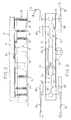
- Figure 1 is a perspective view illustrating two serially connected interior wall panels, which panels mount thereon the improved electrical system.
- Figure 2 is a fragmentary enlarged elevational view showing the electrical system of this invention associated with a bottom edge of a wall panel.
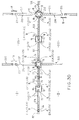
- Figure 3 is a diagrammatic plan view illustrating the modular powerway of the electrical system associated with one panel, and the flexible connectors which electrically connect the powerway to adjacent panels.
- Figure 4 is a perspective view which illustrates the modular powerway which attaches to a single panel.
- Figures 5 and 6 are perspective views which illustrate opposite sides of a power block associated with the modular powerway.
- Figure 7 is an exploded perspective view of the power block.
- Figure 8 is a perspective view showing the inner side of the lowermost housing part shown in Figure 7.
- Figures 9 and 10 are side elevational views which respectively show the inside of the two power block housing parts.
- Figure 11 is a top view of the power block.
- Figures 12 and 13 are enlarged sectional view taken respectively along lines 12-12 and 13-13 in Figure 11.
- Figures 14 and 15 are fragmentary views which illustrate the terminals appearing on the left and right sides, respectively, of Figure 13.
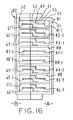
- Figure 16 is an enlarged elevational view showing the terminal appearing on the rightward end of the power block shown in Figure 11.
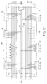
- Figure 17 is an electrical schematic of the power block.
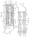
- Figure 18 is a perspective view of a base power feed assembly.
- Figure 19 is a plan view of the base feed assembly shown in Figure 18.
- Figure 20 is an elevational view taken generally along line 20-20 in Figure 19.
- Figure 21 is an right side elevational view of the assembly as shown in Figure 20.
- Figures 22 and 23 are end and side elevational view of a ceiling or top feed assembly.
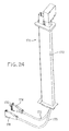
- Figure 24 is a perspective view showing an alternate form of the top feed assembly.
- Figures 25 and 26 are perspective views which respectively show the front and rear sides of a switchable receptacle unit which can be detachably coupled to either side of each power block.
- Figure 27 is a perspective view illustrating a conventional flexible electrical connector which is used for transferring electrical power between the power blocks of adjacent panels.
- Figure 28 is a fragmentary sectional view of one end of the flexible connection of Figure 27.
- Figure 29 is an enlarged fragmentary sectional view along line 29-29 in Figure 28.
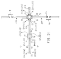
- Figures 30 and 31 are diagrammatic illustrations of plan views showing arrangements of panels to define workstations, and particularly illustrating different applications of the electrical system according to the present invention.
- Figure 32 is a fragmentary side view showing a known Power Base powerway mounted on a panel.
- Figure 33 is a plan view of the arrangement of Figure 32.
- Figure 34 diagrammatically illustrates a variation of the invention whereby three powered panels in a T connection are electrically connected.
- Figure 35 is a view similar to Figure 34 but illustrating a variation thereof.
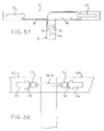
- Figure 36 is a further view similar to Figure 34 but illustrating still a further variation.
- Figure 37 diagrammatically illustrates a electrical connection of two power panels according to the invention when one of the panels has its edge connected transversely to the other panel at a location intermediate the edges of the other panel.
- Certain terminology will be used in the following description for convenience in reference only, and will not be limiting. For example, the words "upwardly", "downwardly", "rightwardly" and "leftwardly" will refer to directions in the drawings to which reference is made. The words "inwardly" and "outwardly" will refer to directions toward and away from, respectively, the geometric center of the panel or powerway and designated parts thereof. Said terminology will include the words specifically mentioned, derivatives thereof, and words of similar import.
- Referring to Figure 1, there is illustrated a
wall system 11 formed from a series of interconnected upright prefabricated panels, only two substantiallyidentical panels - Each panel, such as the
panel 12, includes an internal rigid rectangular frame formed by parallel top and bottom rails rigidly joined together by parallel side rails, thebottom rail 14 being partially illustrated in Figure 2. These rails are typically channel-shaped and open inwardly of the panel, whereby the frame confines therein a suitable core structure, such as a honeycomb layer or similar conventional structure. The core and frame are normally sandwiched between thin facing sheets disposed on opposite sides of the frame, which sheets in turn are normally covered by a suitable fabric, the latter defining exterior side surfaces 15 of the panel, which side surfaces are normally vertically enlarged planar surfaces. - To provide access to electrical power in work areas or workstations defined by or adjacent the wall system, an
electrical system 16 is associated with and extends along the wall system. Theelectrical system 16, as diagrammatically illustrated in Figures 2 and 3, includes an electrically prewiredmodular powerway 17 which is adapted for attachment to an individual panel, such as thepanel 12 in Figure 2, with a plurality of serially connected such panels each having apowerway 17 mounted thereon. Thesepowerways 17 as provided on adjacent panels are then electrically connected together by panel-to-panel connectors 18 (hereinafter referred to as "jumpers") which create a releasable pluglike electrical connection with the adjacent powerways. - The
powerway 17 can also have apower feed unit 141 coupled thereto to supply electrical power into thesystem 16 from an external power source. One or moreremovable output units 181, commonly referred to as receptacle units, can also be engaged with thepowerway 17 to provide electrical access for conventional plugs associated with devices such as typewriters, computers and the like. - The
powerway 17 is typically positioned within autility raceway 21 which is associated with the panel and extends longitudinally therealong, which utility raceway conventionally and commonly extends along the lower edge of the panel directly adjacent the floor. Thisraceway 21 defines an elongate channel orspace 22 which extends longitudinally throughout the length of the panel and is defined between generally parallel side covers 23 which secure to the panel for enclosing the channel. These side covers 23 are generally removable, and are substantially flush with or disposed slightly outwardly relative to the adjacent panel side surfaces 15. - As illustrated by Figures 2-4, the
modular powerway 17 includes at least one and preferably a pair of substantiallyidentical power blocks raceway 28 which extends therebetween, the latter containing therein a plurality of conductors or wires 27 (Figure 6) which at opposite ends project into the interior of the power blocks 25 and 26. The plurality ofwires 27, in the preferred embodiment, include fourteen conductors which are grouped so as to define six separate electrical circuits which extend along the modular powerway 17 and hence along the electrical system, as explained hereinafter. - The power blocks 25 and 26 are substantially identical, and in fact structurally and functionally correspond to one another except that the one power block is rotated horizontally 180° relative to the other power block, so that only the
power block 25 will be described below. - The
power block 25 includes ahollow housing 29 in which a plurality of longitudinally elongate conductive elements orplates 31 are mounted in spaced relation from one another. The number of suchconductive plates 31 corresponds to the number ofconductive wires 27, this being fourteenplates 31 in the illustrated embodiment, although only three such plates are shown in Figure 7 for convenience of illustration. Each of theconductive plates 31 is joined to a respective one of theconductive wires 27. - The
power block 25 defines thereon anelectrical port 32 which is defined at the outer end of the power block and is oriented so as to be accessible in the longitudinal direction thereof, thisport 32 also being oriented toward the adjacent end of the panel. Theelectrical port 32 functions as a terminal for permitting electrical power to be supplied to and from the powerway, and may herein be referred to as an input/output port or terminal assembly. -
Power block 25 has a further pair ofelectrical ports 33 formed thereon adjacent the opposite end thereof, namely adjacent the inner end of the power block, with theseports 33 being generally transversely aligned relative to the power block and oriented so as to face or open outwardly in opposite directions toward the opposite sides of the respective panel. Theseelectrical ports 33 are also used for inputting of electrical power to the powerway, and may also be referred to as input ports or terminal assemblies. - A still further pair of
electrical ports 34 are provided on thepower block 25, these also being disposed on opposite sides of the power block and transversely oriented so as to face outwardly toward opposite sides of the panel. Theseports 34 are disposed intermediate the longitudinal ends of the power block and, in the illustrated embodiment, are longitudinally displaced from one another. Theports 34 cooperate with output units, such asreceptacle units 181, and may herein be referred to as output ports or terminal assemblies. - Lastly, the
power block 25 has a further pair ofelectrical ports 35 associated therewith, whichports 35 are generally aligned and project transversely from opposite sides of the power block so as to project toward the opposite sides of the power block. Theports 35 cooperate with theflexible jumpers 18 which transfer electrical power between thepowerways 17 of adjacent panels, and may herein be referred to as the transfer ports or terminal assemblies. Theports 35 are disposed adjacent the longitudinally outer end of the power block and are positioned closely adjacent the endwise facingport 32. - As to the plurality of
conductive plates 31 which are supported within each power block, this plurality includes two separate groupings each containing six different conductive plates in the illustrated embodiment, with two additional plates being ground plates which are common or shared by both groupings, as explained below. These two groupings are positioned and configured so as to cooperate with only one side of the power block so as to permit access to electrical power from the designated side. The two groupings of conductive plates will, for convenience in reference, be referred to as the A and B groups, which groups respectively cooperate with the A and B sides of the power block as illustrated in Figures 3, 11, 12, 13, 16 and 17. - As to the grouping of plates associated with the A side of the power block, this grouping includes
plates plate plate plates plates plates - The conductive plate 41 (as well as each of the plates 42-46) comprises an
elongate bus 51 which extends longitudinally throughout substantially the length of the power block housing and has a generally Z-shaped cross section which includes a vertical plate part which at its upper end is joined to a sidewardly projectinghorizontal plate part 52. The vertical plate part at its lower end joins to a further horizontal plate part 53 (Figure 7) which projects sidewardly in the opposite direction from thetop plate part 52. Thebottom plate part 53 in turn has a plurality of contacts orterminals 54 projecting outwardly in generally coplanar relationship therewith, which contacts orterminals 54 project sidewardly toward only one side of the power block, namely the A side thereof. As illustrated by theconductive plate 41 in Figure 7, eachconductive plate 41 through 46 has fourcontacts 54 projecting sidewardly therefrom in longitudinally spaced relationship therealong, these four contacts being identified as 41-1 through 41-4 in Figure 7. Eachplate 41 through 46 also has a tab 41-5 located at the longitudinally inner end of the power block and provided with acrimp 55 thereon, the latter being mechanically coupled in a conventional manner to one end of a respective one of theconductive wires 27. The two terminals 41-1 and 41-2 as located closely adjacent the outer longitudinal end of the power block are separated by anintermediate slot 56, and in similar fashion the terminal 41-4 and tab 41-5 which are closely adjacent one another at the longitudinally inner end of the power block are also separated by anarrow slot 57. The remaining contact 41-3 projects sidewardly intermediate the ends of thebus 51. - The other grouping of the
conductive plates 31, namely the group B which cooperates with the B side of the power block, also includes six conductive plates in the illustrated embodiment and specifically includes the six plates 61-66. Eachplate plates plate plate - The conductive plate 61 (as well as each of the plate 62-66) is constructed generally similar to the
plate 41 in that it includes a longitudinally elongatedbus 67 which is of a generally Z-shaped cross section and includes a vertical plate part which at its lower end is joined to a sidewardly projectinghorizontal plate part 68. The upper end of the vertical plate part in turn joins another horizontal plate part 69 (Figure 7) which projects sidewardly in the opposite direction and defines thereon a plurality of horizontally sidewardly projectingcontacts 70, there being four such contacts disposed in longitudinally spaced relationship along therespective bus 67, these contacts being designated 61-1 through 61-4. Plate 61 (as well as each plate 62-66) has a tab 61-5 at the longitudinally inner end of the bus, which tab has acrimp 71 fixed thereto, the latter being connected to one end of arespective conductor 27. The contacts 61-1 and 61-2 are disposed closely adjacent one another at the longitudinally outer end of the bus and are separated by anarrow slot 72 therebetween. Similarly contact 61-4 and tab 61-5 are disposed adjacent the longitudinally inner end of the bus and are separated by anarrow slot 73 therebetween. The remaining contact 61-3 as located intermediate the ends of the bus. - The remaining
conductive plates Plates plate 47 being what is often referred to as the "common" ground, andplate 48 being an "isolated" ground. - As to the construction of the conductive plate 47 (as well as the
plate 48 which is identical thereto), it comprises anelongate bus 75 which is a generally flat longitudinally extending plate part to which a plurality of terminals orcontacts 76 are joined and which project horizontally towards opposite sides of the power block. Specifically, a set of four such contacts projects sidewardly from each side of thebus 75, namely a first contact 47-1A and 47-1B adjacent the longitudinally outer end of the power block, a second contact 47-2A and 47-2B disposed closely adjacent the respective contact 47-1A and 47-1B but separated therefrom by a narrow slot, a third contact 47-3A and 47-3B disposed intermediate the ends of the bus, and a fourth contact 47-4A and 47-4B located closely adjacent the inner longitudinal end of the bus. The contacts 47-1, 47-2 and 47-4 of these two sets are generally transversely aligned relative to the bus, while the remaining contacts 47-3 are longitudinally offset, as appearing in Figure 7. Thebus 75 also has a tab 47-5 at the longitudinally inner end thereof, the latter being provided with acrimp 77 to which one end of a respectiveconductive wire 27 is joined. - Considering now the construction of the
hollow housing 29 for the power block, the housing is primarily defined by twoside housing parts 81 and 82 (Figures 7-16) which are preferably constructed of an electrically insulative material, such as by being molded of a plastic material. The twoside housing parts interior chamber 83 to accommodate therein the A and B groupings ofconductive plate 31. Theinterior chamber 83 is defined generally betweenhousing side walls bottom walls side wall 85 for abutment against theother side wall 84. The walls 85-87 are part of theside housing part 81, which part also includes a plurality ofdivider walls 88 which project horizontally from theside wall 85 in generally parallel but spaced relationship between the top and bottom walls. Most of thesedivider walls 88 extend longitudinally throughout a majority of the length of the power block housing, and the plurality ofdivider walls 88 are themselves vertically spaced apart so that thedivider walls 88 and their cooperation with the top andbottom walls separate chambers 89 which extend longitudinally of the housing but are disposed vertically one above the other. - Each of the three uppermost and three
lowermost chambers 89 accommodates therein, in spaced relation, two of theconductive plates 31, one associated with each of the A and B groups. For example, theuppermost chamber 89 shown in Figure 12 accommodates theconductive plates lowermost chamber 89 accommodates theconductive plates - The
side housing part 81 also has a plurality of longitudinally elongate, parallel, and vertically spacedseparator walls 91 projecting horizontally inwardly in cantilevered fashion from theside wall 85. One of theseseparator walls 91 projects inwardly a limited extent into each of the three uppermost and threelowermost chambers 89, with theseparator wall 91 being spaced upwardly a small distance from the respectivelyadjacent divider wall 88 to define anarrow slot 92 therebetween, which slot effectively accommodates and confines the lower leg of the respective group B conductive plate (such as plate 61) associated with that compartment. - In similar fashion, the
other housing part 82 also has a plurality of longitudinally elongated, parallel, and vertically spacedseparator ribs 93 fixed thereto and projecting horizontally inwardly in cantilevered relation from theside wall 84. One of theseseparator ribs 93 projects inwardly into each of the three uppermost and threelowermost cavities 89, with therib 93 projecting inwardly a limited distance at an elevation above theseparator wall 91 associated with the same compartment. Thisseparator rib 93 is also spaced downwardly a small distance from the respectively adjacent divider wall 88 (or the top wall 86) to define therebetween anarrow slot 94 which confines therein the top leg of the respective group A conductive plate, such as the top leg of theplate 41, associated with that compartment. - In addition, as illustrated in Figure 12, the
separator wall 91 andseparator rib 93, which cooperate with asingle cavity 89, cooperate so as to confine the two conductive plates of that cavity (such as theplates 41 and 61) in spaced relationship generally one above the other and at the same time maintain the conductive plates properly confined between theopposed side walls opposite side walls - The
housing part 81 has a tubular shroud 101 (Figures 13 and 14) projecting transversely outwardly relative to the respective side wall and defining a part of therespective port 35. Thisshroud 101 is of a vertically-elongated rectangular cross section and the interior thereof is horizontally bisected by a plurality ofdivider plates 102 which are disposed in uniformly vertically spaced relationship throughout the height of the shroud so as to divide the shroud into eight vertically stacked compartments 103. The divider plates are a part of and constitute sideward extensions associated with therespective divider walls 88, and likewise therespective compartments 103 within theshroud 101 associated with thehousing part 81 open inwardly in full communication with theinterior compartments 89 as shown in Figure 13. Each of thecompartments 103 accommodates therein one of the contacts associated with therespective port 35, these specifically being the contacts 41-2 through 48-2 as illustrated in Figure 14, thereby defining the overallrespective port 35 on the A side of the power block. - As to the
other port 35 as associated with the B side of the power block, which port is defined on thehousing part 82, it also is defined by a vertically-elongated rectangular shroud 106 (Figures 7 and 15) which projects horizontally outwardly from theside wall 84, with the interior of thisshroud 106 being divided by a plurality of vertically spaceddivider plates 107 into a plurality ofcompartments 108 which are vertically disposed one above the other, with thesecompartments 108 opening horizontally at their outer ends. Thedivider plates 107 are substantially horizontally coplanar with thedivider walls 88 associated with theother housing part 81. While the inner ends of thecompartments 108 are closed off by theside wall 84, nevertheless this side wall has a plurality of horizontally elongated slots 109 (Figure 8) extending therethrough, whichslots 109 are vertically spaced apart so that each slot communicates generally with the center of a respective one of thecompartments 108, thereby permitting theindividual compartments 108 to respectively communicate with a respective alignedinterior chamber 89. Theslots 109 enable the terminals 61-2 through 66-2, as well as the terminals 47-2 and 48-2, to project horizontally into therespective compartments 108 as illustrated by Figures 13 and 15. - With respect to the
ports housing part 81, each of theports port 35 as described above, so that further detailed description thereof is believed unnecessary. However, it should be noted that theport 33 receives therein the terminals designated "-4" as associated with theconductive plates 41 through 48, whereas theport 34 receives the terminals designated "-3" associated with the same conductive plates 41-48. In addition, theside wall 85 has a row of vertically spacedslots 90 opening therethrough for accommodating the terminals associated with theport 34. - With respect to the three
ports other housing part 82, theports port 35 so that further detailed description thereof is believed unnecessary, except theport 33 receives the terminals designated "-4" and theport 34 receives the terminals designated "-3", as associated with the conductive plates 61-66 and 47-48. - With respect to the
port 32 which is formed at the outer end of the housing and projects in the endwise direction, this is also defined by a generally tubular shroud which is of a vertically-elongated rectangular cross section and is defined by the cooperation of generally opposed U-shaped wall structures associated with thehousing parts dividers wall 88 associated with thehousing part 81, as well as horizontallycoplanar dividers walls 112 associated with theouter housing part 82, whereby thesewalls shroud 111 into a plurality of vertically stackedcompartments 113 which open endwise of the housing, there being eight such compartments. Eachcompartment 113 receives therein, along one side thereof, the terminals designated "-1" associated with one grouping of conductive plates, and similarly each compartment receives therein adjacent the other side thereof the terminals designated "-1" associated with the other grouping of conductive plates. Theport 32, as shown in Figure 16, defines two sidewardly-spaced, vertically-oriented rows of eight contacts, the eight contacts on the side of thehousing part 81 being the contacts 41-1 through 48-1 as associated with one grouping of conductive plates, and the contacts 61-1 through 66-1 as well as 47-1 and 48-1 being associated with the other grouping of conductive plates. - The power block housing, at the inner end thereof, defines therein an enlarged
interior chamber 116 for accommodating the connectors (such as theconnectors conductive plates 31 to the plurality ofconductive wires 27. Thewires 27 project into thisinterior chamber 116 through anopening 117 defined at the upper inner end of the power block housing. - The
housing part 81, adjacent opposite ends thereof, also includes a pair of vertically-extending support walls orribs 118 and 119 (Figure 10), the latter having a plurality of vertically spaced slots formed therein so as to supportingly accommodate the plurality of conductive plates in vertically but closely spaced relationship as illustrated by Figures 12 and 13. - Each of the power block housings also has a plurality of support posts 121 (Figure 5) secured thereto and projecting upwardly therefrom. These posts engage the underside of an elongated support rail 122 (Figure 4) which is hat shaped in cross section and extends longitudinally of the
powerway 17 for permitting the twopower blocks support rail 122 for engagement within the support posts 121. Thissupport rail 122 also has a plurality ofopenings 123 formed therethrough, which openings cooperate with suitable fasteners, such as conventional quarter-turn locking cams which are carried on the bottom frame rail of the panel to permit the powerway to be fixedly but releasably secured to the panel. - With the construction and assembly of the
power block 25 as described above, the conductive plates and their cooperation with the ports 32-35 provide electrical paths which are diagrammatically illustrated in Figure 17. As indicated by this latter figure, the threeports end port 32. As to theports ports connector 32. - In the normal and preferred embodiment of the invention, the individual
conductive wires 27 at one end thereof connect to the respective individual conductive plates associated with thepower block 25 in the manner diagrammatically illustrated in Figure 17. The other ends of theseconductive wires 27, however, connect to the conductive plates associated with theother power block 26 in generally a reverse manner so that the circuits C1-C3 are accessible from the power blocks 25 and 26 from the same side of the panel, and the circuits C4, C5 and C6 are accessible from the power blocks 25 and 26 from the opposite side of the panel. - To electrically interconnect adjacent panels such as
panels electrical jumpers 18 which are diagrammatically illustrated in Figure 3. - The
electrical jumper 18 as shown in Figures 27-29 includes a pair of rigidinsulative housing parts 131 which are joined together by an intermediateflexible hinge portion 132, the latter being formed as a substantially flat but flexible strap which can be readily hinged in a horizontal plane so as to accommodate and permit the desired angular relationship between adjacent serially connected panels. A plurality, here eight, ofelectrical wires 134 extend through thehinge part 132 and terminate in a plurality, here eight, of electrical conductors as associated with eachhousing part 131, which conductors each include a pronglike conductive contact 135 (Figure 29) which projects sidewardly of the housing. The eightcontacts 135 are vertically spaced apart and are individually surrounded by substantially rectangularsleevelike shrouds 136 which are normally of a plastics material and formed integrally with thehousing part 131. Thecontacts 135 and surroundingshrouds 136 define a plug-inconnector portion 138 which can be plugged into theport 35 associated with the power blocks to electrically connect the eight-wire system from panel-to-panel. - The
contacts 135 as associated with theconnector portion 138 may be of any conventional configuration, and typically are a resilient forklike contact employing two blades which are spring-urged toward one another so as to provide for proper electrical contact with one of the contacts associated with theport 35 when theconnector portion 138 is engaged with theport 35. Reference is made to U.S. Patent No. 5 236 370, owned by the Assignee hereof, which illustrates the construction of such contact. - The
electrical jumper 18 is normally provided in at least two lengths, with one primary length being suitable for connecting two adjacent panels when they are either directly aligned or in angled relationship with one another as indicated by thejumper 18 as diagrammatically shown in Figure 3. However, if the jumper is to electrically join aligned panels which are somewhat spaced apart due to three panels defining a T-shaped configuration, then theintermediate strap 132 will be of greater length so that the jumper can span across the gap between adjacent panels, such as indicated at 18' in Figure 3. - To supply electrical energy to the
electrical system 16, this is most frequently accomplished by connection to a power source or monument which is located either on the floor or on an adjacent wall. The electrical energy is supplied to the panel system from the monument by an assembly commonly know as a base feed assembly, such assembly being indicated at 141 in Figures 2 and 3. - The
base feed assembly 141 of the present invention is shown in greater detail in Figures 18-21 and includes ablocklike housing 142 having a power-supply conduit 143 connector thereto through asuitable elbow connection 144. The housing orbox 142 is intended to be positioned within the raceway between the side cover substantially as illustrated by Figures 2 and 3, and the housing is provided with suitable clips or fasteners, such as indicated at 150, to secure the housing to the support rail. - The power-
supply conduit 143 has a plurality of electrical conductors (i.e., wires) 145 extending therealong, there being fourteen such wires in the illustrated embodiment. These wires at their remote ends are suitably connected to appropriate terminals associated with the power-supply monument. The wires then project into thebox 142 for association with a pair offlexible straps 146 which project from thebox 142 for connection to a power block. - Each
flexible strap 146 contains therein a plurality of conductive wires 147 extending longitudinally therealong, which wires are generally overmolded by the plastic strap and at their inner ends connect to the respective power-supply conductors 145 which project into thebox 142. The plurality of conductive wires 147 include at least three hot and three neutral wires so as to define three circuits, and at least one ground wire. In the illustrated embodiment, the plurality of wires 147 in eachstrap 146 is seven, with the seventh wire in one strap being the common ground, and the seventh wire in the other strap being the isolated ground. However, it will be apparent that the plurality of wires 147 in each strap can be eight since each strap can be provided with both the common and isolated grounds. - The
strap 146 at its outer or free end is provided with aterminal block 148 which, on the inner side thereof, defines a connector orterminal assembly 149. This terminal assembly includes a plurality, here seven, of sidewardly projecting tubular shrouds each containing an electrical contact therein, which contact is connected to a respective one of the conductive wires 147. The terminal block is generally molded of a suitable insulative material, normally a plastic material. The contacts associated with each shroud of theterminal assembly 149 are also normally constructed in the same manner as the contacts associated with theflexible connector 18. - The
terminal assembly 149 is designed to create a plug-type engagement with one of theports 32 associated with the power block to supply electrical energy to the power block through the seven conductors associated with the respectiveflexible strap 146. - Since the
block 142 has a pair of substantial identicalflexible strap 146 formed thereon, which flexible straps each terminate in aterminal assembly 149 which is disposed substantially directly opposed to the terminal assembly on the other flexible strap, this enables the two flexible straps to be positioned so as to effectively straddle the power block, whereby theterminal assemblies 149 associated with the twoflexible straps 146 plug into theopposed ports 33 defined on opposite sides of the power block, as illustrated in Figure 3. Since the seven conductive wires 147 associated with each flexible strap include three distinct hot and three distinct neutral conductive wires which are all connected to different power-supply conductors 145, this enables six distinctly different electrical circuits to be supplied to the power block when bothflexible straps 146 are plugged into the power block. - As a modification, instead of two
flexible power straps 146 projecting outwardly in the same direction from one end of thebox 142, alternately the two straps can project outwardly in opposite directions from thebox 142 so that one strap will plug into a power block at one end of the panel, and the other strap will plug into a power block adjacent the other end of the panel. - In those situations when electrical power is to be supplied from a power monument located in the ceiling, then a ceiling power feed assembly 151 (Figures 22 and 23) is utilized. This assembly includes a vertically-elongate
tubular shroud 152 which is adapted to be slidably inserted through an interior channel defined vertically along one edge of the panel, with the shroud projecting upwardly into the vicinity of the ceiling. Araceway 153 extends interiorly of theshroud 152 and confines therein a plurality ofconductive wires 154, i.e. fourteen wires in the illustrated embodiment. Thesewires 154 at their upper ends connect to the power source at the ceiling monument. The lower end of theraceway 153 projects downwardly from the shroud and joins to aconnector housing 156 which contains therein a plurality of conductive members orplates 157 as indicated by dotted lines in Figure 23. Each of theseconductive plates 157 has the lower end of a respective one of theconductive wires 154 connected thereto. Each conductive plate has acontact 158 attached thereto, which contact projects outwardly of the housing and is surrounded by a generallyU-shaped shroud 159 which is fixed to the housing. Thecontact 158 is normally a bifurcated or forklike contact, as generally described above. Theshrouds 159 andrespective contacts 158 are disposed in two sidewardly-adjacent vertically-oriented rows each containing eight contacts as illustrated by Figures 22 and 23, with each of the vertical rows having a common contact for the isolated ground and a common contact for the common ground. The other six contacts associated with each vertical row respectively connect to three distinct hot and neutral conductive wires so that connectors orterminal assemblies - With the
shroud 152 andraceway 153 inserted into and projecting downwardly through a channel adjacent the vertical edge of the panel, this results in theterminal block 156 being disposed adjacent the end of the respectivelyadjacent power block terminal assemblies end port 32 on the power block so as to supply six-circuit electrical power thereto. - An alternative ceiling
power feed assembly 171 is illustrated in Figure 24. This assembly again connects to a ceiling-positioned electrical monument and has atubular shroud 172 which projects downwardly through the interior of the panel and confines therein an electrical conduit which, at least at the lower end, is separated into twoconduits 173 each containing at least seven electrically conductive wires, namely three neutrals, three hots, and at least one ground. The hots and neutrals associated with eachconduit 173 are distinct so that the twoconduits 173 supply six distinct electrical circuits. Eachconduit 173 includes an elongate flexible portion which is adapted to extend along the bottom raceway of the panel, and the conduit terminates in aconnector housing 174 which defines thereon a sidewardly projecting connector portion orterminal 175. Theconnector housing 174 and therelated terminal 175 is substantially identical to the end terminals associated with the base feed assembly. The twoconduits 173 can be disposed to extend along the raceway so that the twoconnector housing 174 are disposed so as to straddle the power block adjacent the remote end of the raceway, with the terminals orconnectors 175 being plugged into theports 33 disposed adjacent the inner end of the power block. - To permit external electrical devices to access the electrical circuits available at the power blocks, each
power block ports 34. - The
output assembly 181, as illustrated by Figures 25 and 26, comprises a receptacle unit which, when mounted on the power block, is accessible through a small window or cutout 182 (Figure 1) which is formed in the side cover. The receptacle unit is defined by a generallyboxlike housing 183 which, on the front face, is typically provided with one, two or three conventional three-holeelectrical sockets 184 so as to accommodate a conventional two or three prong 110-volt plug. The three-hole socket 184 cooperates with suitable electrical conductors which are disposed interiorly of thehousing 183, which conductors in turn cooperate with aterminal assembly 185 which projects rearwardly from the rear side of the housing for creating a plug-type engagement with theport 34. - The
terminal assembly 185 includes a pair of rearwardly projectingtubular shrouds shrouds housing slot 190, whereby theshrouds connector 34. The remainingshrouds shroud 188 is designed to contain a common ground contact, and theshroud 189 is designed to contain an isolated ground contact, with only a selected one of these ground contacts being provided. - The overall construction of the receptacle unit is explained in detail in U.S. Patent No. 4 781 609, owned by the Assignee hereof, so that further detailed description thereof is believed unnecessary. The basic difference between the
receptacle unit 181, and the receptacle unit disclosed in the '609 patent, is that the receptacle in the '609 patent possesses only a single ground and shroud, rather than twoshrouds receptacle unit 181 is well known inasmuch as this unit is a commercially available unit sold by the Assignee hereof as part of its Power Base system. - While the
receptacle unit 181 described above is of the switchable type so as to permit a single receptacle unit to access all three circuits which are available on one side of the power block, it will be appreciated that numerous other types of receptacle units can be utilized for this purpose. For example, while less desirable, nevertheless three different receptacle units can be provided each dedicated for connection to only a predetermined one of the different circuits associated with the power block, such dedicated receptacle units being conventional and well known. - The use and operation of the improved
electrical system 16 of this invention will be briefly described below, and in this respect reference will be made to the diagrammatic illustration in Figure 30. - The improved
electrical system 16 of this invention is particularly desirable for supplying a large number of distinct electrical circuits (six in the illustrated embodiment) along a series of panels (i.e. a spine) which cooperate with branch panels to define a plurality of workstations, As indicated in Figure 30, the series of panels designated 12A-12E are disposed in generally aligned relationship to define a spine, with additional panels designed 201 through 204 branching off from the spine panels substantially at right angle thereto so as to define workstations, two such workstations being indicated at 206 and 207. The series ofmain panels 12A-12E effectively function as a spine for both supportive engagement with the branch panels 201-204, and for supplying electrical energy from the spine or main panels to the branch panels. - The
spine panels 12A-12E, in the illustrated embodiment, each have a prewiredmodular powerway 17 mounted thereon which positions therespective power blocks respective power blocks powerway 17 and the power blocks thereof wired as described above, the side A ofpower block 25 and the side B ofpower block 26, both on the side of the spine designated side I, provide access to the same three circuits, such as circuits C1, C2 and C3 as depicted in Figure 30. Similarly, as to this same panel 12a, the B side ofpower block 25 and the A side ofpower block 26 both provide access to the other three circuits, namely the circuits C4, C5 and C6, on the side II of the spine. - Power is typically supplied to the spine through the
base feed 141 as diagrammatically depicted in Figure 30, which base feed can be connected to any one of thespine panels 12A-12E. - To transmit the plurality of electrical circuits between adjacent serially arranged panels in the spine, such as the
panels 12A and 12B, two identicalflexible jumpers 18 are utilized for transmitting the circuits between the power blocks of adjacent panels. For example, the twoflexible jumpers 18 are disposed adjacent opposite sides of the power blocks, such as thepower block 26 on the panel 12B and thepower block 25 on thepanel 12A, with these flexible jumpers being plugged into thetransfer ports 35 associated with the power blocks. Theflexible jumper 18 on the side I effects transfer of the three circuits C1, C2 and C3 between the adjacent panels, and in a similar fashion theflexible jumper 18 on the side II effects transfer of the circuit C4, C5 and C6 between the two panels. - When the main or spine panels cooperate with branch panels to form a T or cross connection, such as the cross connection defined with the
branch panels panel 202, then the flexible jumper is utilized to extend and plug directly into the power blocks 25 and 26 of spineadjacent panels 12B and 12C, such as depicted by the jumper 18'. This latter jumper will normally be of greater length so as to permit spanning the greater gap between adjacent panels, but is otherwise identical to thejumper 18 and permits the transmission of the circuits C4, C5 and C6 between thepanels 12B and 12C. - On the other hand, the branch panel can be electrically powered, as depicted by the
branch panel 201. This panel has a prewiredpowerway 211 thereon, which terminates inpower blocks powerway 211 is shown in Figures 32 and 33, and thepower blocks conductors 214 positioned interiorly thereof, there being eight such conductors in the illustrated and preferred embodiment, three of theconductors 214 being live or hot conductors, three being neutrals, and two being grounds. These eight conductors have shrouded terminals accessible from opposite sides of the power block so as to define a first pair ofports 215 which project outwardly from opposite sides of the power block, as well as a further pair ofports 216 which also project outwardly from opposite sides of the power block. Theports 215 are identical to theports 35 described above and create an electrical plug-in connection with one end of aflexible jumper 18. Theother ports 216 are identical to theports 34 described above and permit thereceptacle unit 181 to be plugged thereto so as to provide access to any one of the three circuits which are defined by theconductors 214. Theseconductors 214 are individually connected toconductive wires 217, there again being eight such wires in the illustrated embodiment, which wires extend through theraceway 218 for connection to the other power block so that both power blocks have the same circuit capability, namely the same three circuits in the illustrated embodiment, with these same three circuits being accessible from both sides of thepower blocks panel 201 to a like panel such aspanel 205. - The
powerway 211 and its cooperation with theflexible jumper 18 for transmitting electrical energy from panel to panel is identical to the powerway arrangement and components therefor as described in U.S. Patent No. 4 781 609, owned by the Assignee hereof, except that the arrangement of the '609 patent discloses only a single ground (i.e, a seven conductor system) rather than a double ground. Further, thispowerway 211 and the flexible jumper utilized therewith are well known, and are commercially sold by the Assignee hereof under "The Power Base" trademark. - To transmit electrical power from the spine panel to the
branch panel 201, theflexible jumper 18 is utilized for connection between power blocks associated with the spine panel 12B and thebranch panel 201. Thisflexible jumper 18 at one end is plugged into thetransfer port 35 provided on the A side of thepower block 25. The other end of thisjumper 18 is plugged into theadjacent side ports 215 provided on thepower block 212 of thepanel 201. This provides for transfer of the three circuits C1, C2 and C3 into thepowerway 211 associated with thebranch panel 201, which three circuits can then be transmitted to other panels along this branch, such aspanel 205. - To continue the transfer of all six circuits along the spine, a
further jumper 18 has one end thereof plugged into theport 216 provided on the other side of thepower block 212 associated with thepanel 201, and thisjumper 18 at its other end plugs into theport 35 associated with the side B ofpower block 26 onpanel 12C. This permits the three circuits C1, C2 and C3 as available at thepower block 212 to be transmitted to thepower block 26 ofpanel 12C, which power block again has all six circuits provided thereto, which six circuits are then transmitted downstream of the spine panels. - If two branches are to be powered from a T or cross, such as the
branch panels separate jumpers 18 are plugged into opposite sides of the power block, such as thepower block 25 on panel 12B. Thejumper 18 joined to the side B ofpower block 25 plugs into thepower block 212 onbranch panel 204, thereby transferring circuits C4, C5 and C6 to thebranch panel 204. Theother jumper 18 which is connected to the side A ofpower block 25 plugs into thepower block 212 onbranch panel 203, thereby transferring circuits C1, C2 and C3 to thebranch panel 203. Each of thebranch panels branch panel 204 are distinct and different from the three circuits accessible from thebranch panel 203, and vice versa, thereby providing for increased selectivity of circuits and distribution of loads on circuits, and at the same time enables a larger number of workstations to be electrically powered from a single electrical input source, such as from asingle base feed 141. - The electrical energy can continue to be transmitted along this spine beyond the
branch panels power block 26 on the panel 12E, with the other ends of thesejumpers 18 being connected to theports 216 provided on opposite sides of thepower blocks 212 associated with thebranch panels - With the arrangement as described above, and such as illustrated in Figure 30, the improved
electrical system 16 of this invention can be utilized within the panels which define the spine or main run of a system, and the conventional "Power Base" system (i.e., the power modules 211) can be provided on the branch panels, thereby enabling the workstations to access a plurality of circuits, with different workstations accessing different pluralities of circuits. This also enables thepowerways 211 associated with the conventional "Power Base" system to be utilized along the panel branches, with theimproved powerway 17 of this invention being used along the main or spine panels, whereby the electrical system associated with the branches is of increased simplicity and is thus more economical to purchase and utilize as part of the overall system. Further, this also enables users to utilize existing panels bearing the "Power Base" system thereon, which existing panels can be utilized in conjunction with theimproved powerway 17 of this invention by utilizing thepowerway 17 on the panels defining the main spine or branch. At the same time, thereceptacle units 181 andflexible jumpers 18 associated with the conventional "Power Base" system are still useable on the branches, and are also useable with the panels defining the spine, since the conventional receptacle units mount on the power blocks of thepowerway 17, and theconventional jumpers 18 are useable for connecting the power blocks of twopowerways 17, or for connecting the power block on apowerway 17 with the power block of aconventional powerway 211. - Figure 31 illustrates a variation which can be incorporated into the
modular powerway 17 of the present invention. In this variation, the two groupings of conductive wires which connect the twopower blocks power blocks modular powerway 17. This results in the ports accessible from the A side ofpower block 26 on panel 12F being connected to three circuits such as circuits C1, C2 and C3, and similarly the ports on the A side of thepower block 25 of panel 12F are also connected to the same three circuits, namely C1, C2 and C3. In similar fashion, the ports provided on the B side of the power blocks 25 and 26 on panel 12F are all connected to the other grouping of three circuits, namely the circuits C4, C5 and C6. This thus results in side I and side II of the panel 12F accessing all six circuits. For example, on the side I, thepower block 25 accesses circuits C1 through C3, and thepower block 26 accesses circuits C4 through C6. On the opposite side II, thepower block 25 accesses circuits C4 through C6, and thepower block 26 accesses circuits C1 through C3. This criss-cross relationship may continue between the power blocks of respective panels as the panels are serially connected together as depicted in Figure 31. This thus enables all six circuits to be readily and conveniently accessible on both sides of the panels defining the main branch or spine. - In addition, as also shown in Figure 31, the panels mounting thereon the
modular powerway 17 of this invention can also be connected to branch panel runs which utilize the conventional "Power Base" system therein, such as depicted by thepanels panel 204, and the circuits C4, C5 and C6 along thepanel 203. - Three or more electrified panels mounting thereon the multiple-circuit
modular powerway 17 of this invention can also be connected in a T or cross-shaped configuration so as to permit electrical power from a single branch of panels to be supplied to two or more branches of panels. Such connection involving a T or three-panel connection is illustrated by Figures 34 and 35. - As shown initially in Figure 34, three
panels 12, 12L and 12R have adjacent edges disposed to form a three-panel connection, commonly known as a T connection. Each of these three panels is provided with themodular powerway 17 of this invention thereon, but only thepower block 25 onpanel 12 andpower blocks port 35 ofpower block 25 for connection to the three circuits available at this port. This jumper 18-1 is provided with two flexible straps 132' which project from this connector 138', and each of these straps 132' have at least the same seven conductive wires extending therethrough for transmitting the same three circuits, and each strap 132' terminates in a similar connector 138' at the other end, one of which connects to one of theports 35 on thepower block 26L, and the other of which connects to one of theports 35 on theother power block 26R. The other flexible electrical jumper 18-2 is constructed similar to the jumper 18-1 in that it also has a connector 138' on one end thereof which connects to theother port 35 associated with thepower block 25, and two flexible straps 132' project outwardly therefrom and have connectors 138' at the other ends thereof which individually join to the remainingports 35 associated with thepower blocks - With the arrangement illustrated in Figure 34, the one jumper 18-1 is capable of transmitting three of the circuits between the three connected panels, and the other jumper 18-2 is capable of transmitting the remaining three circuits between the three connected panels.
- In Figure 35, there is depicted a similar T connection between three panels which each again mount the modular powerway of this invention thereon, such being depicted solely by the power blocks 25, 26L and 26R associated with the respective panels. In this variation, a flexible electrical connector or jumper 18-3 is provided for connecting the three power blocks provided on the adjacent edges of the three connected panels. This jumper 18-3 includes a terminal or connector portion T1 at one end which, in this variation, plugs into the
port 32 associated with the end of thepower block 25, whereby this connector T1 electrically accesses or connects to all of the circuits associated with the power block. The jumper 18-3 has two flexible straps projecting outwardly from the connector T1, and each of these straps transmits therethrough a plurality of conductive wires suitable for transmitting all of the circuits of the system, with each strap terminating in a further connector T2 which plugs into theend port 32 associated with one of theother blocks - As shown in Figure 36, particularly in situations where a greater separation distance exists between opposed power blocks on adjacent panels, a single modified flexible electrical connector or jumper 18-4 can be provided for transferring all of the circuits between opposed power blocks on adjacent panels which mount thereon the modular powerway of this invention. In this situation, the opposed
power blocks port 32 associated with the respective power block. These terminals T3 are joined by one or more flexible straps which contain the plurality (here 14) of conductive wires so that all circuits (here 6) associated with the powerways are transmitted between the powerways of adjacent panels. Each connector T3, in a fashion which is also applicable to the connectors T1 and T2 described above, has two sidewardly-spaced vertical rows of shroud-enclosed contacts associated therewith, and these two rows plug into therespective port 32 so as to permit electrical connection with all of the six circuits associated with the power block while at the same time maintaining the distinctiveness of the two groupings of circuits which are associated with opposite sides of each power block. - Referring now to Figure 37, there is illustrated a variation of the invention wherein a
panel 12 of the invention connects perpendicularly to a second panel 12', with each of thepanels 12 and 12' having the modular powerway of this invention associated therewith, such being schematically depicted in the drawings solely by the diagrammatic illustration of thepower block 25 associated with one end of thepanel 12, and the power blocks 25 and 26 associated with opposite ends of the other panel 12'. In this variation, however, the end edges of the panels are not disposed directly adjacent one another, but rather the vertical end edge of thepanel 12 is disposed substantially in abutting relationship with one side face of the panel 12' substantially between the vertical end edges thereof, such as typically at the middle thereof. Thepanel 12 in this variation is secured to the panel 12' by special securing clips or brackets which generally couple thepanel 12 to the panel 12' adjacent the upper and lower edges thereof, such bracket being known in the industry. To permit electrical energy to be transmitted between the two electrifiedpanels 12 and 12' when disposed in the specialized T-connector relationship shown in Figure 37, two flexible electrical connectors orjumpers 18 are provided, which twojumpers 18 have the connectors at one end thereof plugged into theopposed ports 35 associated with thepower block 25 on the intersectingpanel 12. The straps associated with the twojumpers 18 are then disposed so as to extend along the raceway associated with the other panel 12' so that the other end of onejumper 18 plugs into thepower block 26 provided at one end of the panel 12', and theother jumper 18 plugs into thepower block 25 associated with the other end of the panel 12'. In this fashion, all circuits associated with the modular powerway can be transferred between thepanels 12 and 12' while at the same time maintaining the distinctiveness of the two subsets of circuits. - If desired, both straps can be extended interiorly along the raceway so as to plug into the same power block provided on the panel 12', this relationship being depicted by dotted lines in Figure 37. In addition, the straps associated with the
jumpers 18 can be provided with flexible hinges or deviations therein so as to provide for greater length adjustability so as to accommodate connections of this type. - While the preferred embodiment of the invention as described above depicts the use of fourteen conductors associated with the power blocks so as to define the six circuits, it will be appreciated that the circuit subsets associated with each side of the power block could each be provided with separate isolated and common grounds, rather than sharing the common and isolated grounds between the two circuit subsets, whereby sixteen conductors would be provided within each power block, and similarly sixteen conductive wires would be provided for connecting the two power blocks of each modular powerway together.
- In addition, while the invention discloses the circuit subsets associated with each side of each power block as involving three circuits which are all distinct from the three circuits associated with the subset on the other side of the power block, it will be appreciated that the two circuit subsets associated with opposite sides of the power block can share some of the circuits if necessary or desirable. However, in accordance with the present invention, each circuit subset as associated with each side of the power block will each have at least one, and preferably more than one, circuit which is distinct from the circuits associated with the other circuit subset of the same power block.
- While the present invention preferably employs a modular powerway for mounting on a panel wherein the powerway employs two power blocks which are longitudinally spaced apart so that the two power blocks are thus disposed on opposite sides of a central vertical plane which perpendicularly bisect the panel into longitudinal halves, whereby each power block is thus disposed more closely adjacent one edge of the panel than the other edge, nevertheless it will be appreciated that in some instances the modular powerway of the present invention may involve only a single power block per panel, such being particularly suitable for use on smaller panels such as panels of about 24-inch width or less.
- Although a particular preferred embodiment of the invention has been disclosed in detail for illustrative purposes, it will be recognized that variations or modifications of the disclosed apparatus, including the rearrangement of parts, lie within the scope of the present invention.
Claims (20)
- An interior space-dividing wall system, comprising:
first and second upright space-dividing wall panels (12) horizontally serially joined together;
first and second electrical power blocks (25, 26) respectively mounted on said first and second panels, said power blocks being disposed generally between vertical planes which define opposite side surfaces of the panels;
at least one electrical connector unit (18) joined between said first and second power blocks for transmitting electrical energy therebetween, said connector unit having a releasable pluglike electrical connection with each of said first and second power blocks;
each said power block including a set of electrically conductive members (31) which define a plurality of electrical circuits;
said set of conductive members (31) including first and second subsets of conductive members which respectively define first (41-46) and second (61-66) groupings of at least two electrical circuits each, at least one circuit of each grouping being distinct from the circuits of the other grouping;
said set of conductive members (31) also including at least one ground conductor (47);
each said power block including a first electrical port (35) provided adjacent an outer end of said power block for pluglike engagement with one end of said electrical connector unit (18);
each said power block including a pair of substantially identical second electrical ports (34) each adapted for pluglike engagement with an output unit (181), said second electrical ports as defining said pair being provided on and accessible from opposite sides of said power block;
one of said second ports (34) being accessible only from one side of said power block and including a plurality of electrical terminals which are respectively connected to the conductors of said first subset (41-46) so that said one second port can access only said first grouping of circuits;
the other said second port (34) being accessible only from the other side of said power block and including a plurality of electrical terminals which are respectively connected to the conductors of said second subset (61-66) so that said other second port can access only said second grouping of circuits; and
at least one electrical output unit (18) for releasable pluglike engagement with one of the second ports of one said power block, said output unit defining at least one multiple-hole electrical socket (184) for accommodating a two or three prong electrical plug. - A wall system according to Claim 1, wherein each of said first and second power blocks includes a pair of substantially identical said first electrical ports (35) provided adjacent an outer end thereof and each adapted for pluglike engagement with one end of a said electrical connector unit (18), one of said first ports (35) including a plurality of electrical terminals which are respectively connected to the conductors of said first subset (41-46) so that said one first port accesses only said first grouping of circuits, and the other said first port (35) including a plurality of electrical terminals which are respectively connected to the conductors of said second subset (61-66) so that said other first port accesses only said second grouping of circuits.
- A wall system according to Claim 2, wherein first and second said electrical connector units (18) are joined between said first and second power blocks for transmitting electrical energy therebetween, said first electrical connector unit having one end thereof engaged with one of said first ports and said second electrical connector unit having one end thereof engaged with the other of said first ports, said first and second electrical connector units respectively transmitting said first and second grouping of circuits between said first and second power blocks.
- A wall system according to any one of Claims 1-3, wherein the one distinct circuit of one grouping is accessible for connection to a said output unit on only one side of the respective power block, and wherein the one distinct circuit of the other grouping is accessible for connection to a said output unit on only the other side of the respective power block.
- A wall system according to any one of Claims 1-4, wherein each said power block (25, 26) includes a third electrical port (32) for permitting an electrical power in-feed assembly (151) to be connected to said power block by a plug-type engagement for supplying said plurality of electrical circuits to said power block, said third electrical port having a plurality of electrical terminals which are respectively connected to all of the conductive members (31) of said set so as to access all of the circuits of both groupings.
- A wall system according to Claim 5, wherein said third port (32) includes two sets of terminals with the terminals of one set being connected to the circuits of one grouping and the terminals of the other set being connected to the circuits of the other grouping.
- A wall system according to Claim 6, wherein said third port (32) is provided at an outer end of the respective power block and faces in an endwise direction, and wherein the pair of first ports (32) are disposed closely adjacent and slightly inwardly of said third port, said first ports facing sidewardly of said power block in opposite outward directions.
- A wall system according to any one of Claims 5-7, wherein each said power block has a pair of substantially identical fourth electrical ports (33) which are provided adjacent opposite sides of the respective power block and are each adapted for pluglike engagement with one part of a two-part electrical feed supply assembly (141 or 171), one said fourth port (33) having terminals which are coupled to and access solely said one grouping of circuits, and the other of said fourth ports (33) having terminals which are connected to and access solely the other grouping of said circuits.
- A wall system according to any one of Claims 1-4, wherein each said power block has a pair of substantially identical third electrical ports (33) which are provided adjacent opposite sides of the respective power block and are each adapted for pluglike engagement with one part of a two-part electrical feed supply assembly (141 or 171), one said third port (33) having terminals which are coupled to and access solely said one grouping of circuits, and the other of said third ports (33) having terminals which are connected to and access solely the other grouping of said circuits.
- A wall system according to Claim 9, including a power feed assembly (141) connectable to one of said power blocks for supplying said plurality of electrical circuits thereto, said power feed assembly having an elongate electrical conduit providing a plurality of conductive wires therein for defining said plurality of circuits, one end of said conduit being adapted for connection to an electrical power source, said conduit at its other end being connected to a mounting block (142) which secures to said panel, and a pair of flexible and elongated power transmitting parts (146) cantilevered from said mounting block and each transmitting therethrough one of said groupings of electrical circuits, each said power transmitting part terminating in electrical terminals which creates a pluglike engagement with one of said third ports (33) for transmitting the electrical circuits of the respective grouping to the power block.
- A wall system according to any one of Claims 1-10, wherein said first and second panels respectively mount thereon third and fourth power blocks which are longitudinally spaced from the respective first and second power blocks, and first and second multi-conductor conduits (27, 122) respectively provided on said first and second panels for electrically connecting the two power blocks of the respective panel for transmitting said plurality of circuits therebetween, said third and fourth power blocks being substantially identical to the respective first and second power blocks.
- In an upright space-dividing interior wall panel having a raceway extending longitudinally thereof between opposite vertically-extending end edges of the panel, and a pair of electrical power blocks mounted on said panel within said raceway in longitudinally spaced relation, the pair of power block being joined by a multi-conductor conduit for transmitting electrical energy between said pair of power blocks, the improvement wherein each said power block comprises:
a housing (29) defining an interior chamber in which a plurality of electrically conductive members (31) are supportingly positioned in spaced relation to one another, said plurality of conductive members defining first (41-46) and second (61-66) subsets of different conductors which respectively define first and second groupings of electrical circuits, each said grouping defining at least two electrical circuits, the two electrical circuits of one said grouping being distinct from the two electrical circuit of the other grouping;
each said power block (25, 26) including a pair of substantially identical first electrical connector ports (35) provided adjacent an outer end of said power block and each adapted for pluglike engagement with one end of an electrical connector unit (18), each said first port (35) accessing only a respectively different one of said groupings of circuits; and
each said power block (25, 26) including a pair of substantially identical second electrical connector ports (34) each adapted for pluglike engagement with a separable output unit (181), said second electrical connector ports (34) as defining said pair being provided on and accessible from opposite sides of said power block, each said second port accessing only a respectively different one of said groupings of circuits. - A wall panel according to Claim 12, wherein each said power block includes a third electrical connector port (32 or 33) for permitting an electrical power in-feed assembly to be connected to said power block by a plug-type engagement for supplying all of said electrical circuits to said power block.
- In an interior space-dividing wall system including at least first, second and third upright panels respectively having first, second and third upright end edges disposed in close proximity to one another, and first, second and third electrical power blocks mounted respectively on said first, second and third panels, a first electrical connector joined between said first and second power blocks for transmitting electrical energy therebetween, and a second electrical connector joined between said first and third power blocks for transmitting electrical energy therebetween, each said electrical connector having connector portions adjacent opposite ends thereof which create a releasible plug-type engagement with connector ports on the respective power blocks, said first electrical connector having the connector portion at one end thereof engaged with a first said connector port on said first power block, the connector portion at the other end of said first electrical connector being engaged with a said connector port on said second power block, said second electrical connector having a connector portion at one end thereof engaged with a second said connector port on said first power block, and a connector portion on the other end of said second electrical connector being engaged with a said connector port on said third power block, comprising the improvement wherein:
said first power block includes a plurality of electrical conductors (31) therein for defining a plurality of electrical circuits, said first connector port (35) associated with said first power block accessing only a first subset of said plurality of circuits, said second connector port (35) as associated with said first power block accessing only a second subset of said plurality of circuits, each of said first and second subsets including a number of circuits which is at least two but less than said plurality, and each said subset including at least one circuit which is distinct from all of the circuits of the other subset;
said first and second electrical connectors (18) each containing thereon a plurality of electrical conductors which define a predetermined number of circuits equal to said subset, said first electrical connector (18) transmitting only said first subset of said plurality of circuits to said second power block, said second electrical connector (18) transmitting only said second subset of said plurality of circuits to said third power block. - A system according to Claim 14, wherein said second power block (212) includes therein a plurality of conductors which define a select number of circuits equal to only said first subset.
- A system according to Claim 14 or Claim 15, wherein said second power block (212) has two said electrical connector ports (215), each of which is engageable with a said electrical connector (18).
- A wall system according to any one of Claims 14-16, wherein said first power block has a pair of third electrical connector ports (34) provided thereon, said pair of third connector ports being disposed on opposite sides of and accessible from opposite sides of said first power block, said third connector ports being substantially identical and each being adapted to create a releasable plug-type electrical engagement with a separable output unit (181) which defines therein at least one multiple-hole electrical socket, the third connector port (34) on one side of said first power blocks means accessing solely the circuits of said first subset, the third connector port (34) on the other side of said first power block means accessing solely the circuits of said second subset.
- A system according to any one of Claims 14-17, including a fourth panel provided with a fourth upright end edge which is disposed in close proximity to said first upright end edge, a fourth electrical power block mounted on said fourth panel, said fourth power block being substantially identical to said first power block in that it defines thereon first and second connector ports (35) which each respectively access a different subset of the electrical circuits which are defined within said fourth power block, said third power block being substantially identical to said second power block, a third electrical connector (18) joined between said second and fourth power blocks, and a fourth electrical connector (18) joined between said third and fourth power blocks, each of said third and fourth electrical connectors being joined to the respective power blocks by releasable plug type electrical connections.
- A wall system according to any one of Claims 14-17, including a fourth panel serially connected to said first panel and defining thereon a fourth power block which is electrically interconnected to said first power block and defines therein said plurality of circuits, and an electrical feed assembly (141 or 171) for supplying said plurality of electrical circuits into the electrical system which includes said first and fourth power blocks, said electrical feed assembly including an external raceway containing a plurality of conductors which define said plurality of circuits and which projects into a panel raceway containing one of said first and fourth power blocks, said external raceway terminating in a pair of connectors (146 or 173) which each terminate in a connector portion which creates a plug-type electrical engagement with one of said first and fourth power blocks, each last-mentioned connector and the respective connector portion transmitting solely one of said subsets of said plurality of circuits so that the totally of said plurality of circuits are transmitted to the respective power block only when both of said last-mentioned connectors are engaged therewith.
- A system according to any one of Claims 14-19, wherein all of the circuits of one said subset are distinct from all of the circuits of the other subset.
Applications Claiming Priority (2)
| Application Number | Priority Date | Filing Date | Title |
|---|---|---|---|
| US363750 | 1994-12-23 | ||
| US08/363,750 US5607317A (en) | 1994-12-23 | 1994-12-23 | Electrical powerway for furniture panel |
Publications (2)
| Publication Number | Publication Date |
|---|---|
| EP0718943A2 true EP0718943A2 (en) | 1996-06-26 |
| EP0718943A3 EP0718943A3 (en) | 1997-07-23 |
Family
ID=23431564
Family Applications (1)
| Application Number | Title | Priority Date | Filing Date |
|---|---|---|---|
| EP95120168A Withdrawn EP0718943A3 (en) | 1994-12-23 | 1995-12-20 | Electrical powerway for furniture panel |
Country Status (3)
| Country | Link |
|---|---|
| US (2) | US5607317A (en) |
| EP (1) | EP0718943A3 (en) |
| CA (1) | CA2165353A1 (en) |
Cited By (3)
| Publication number | Priority date | Publication date | Assignee | Title |
|---|---|---|---|---|
| EP1777790A1 (en) * | 2005-10-24 | 2007-04-25 | Wexio AB | A system for safe distribution of electrical current or electrical signals |
| WO2007046761A1 (en) * | 2005-10-19 | 2007-04-26 | Ncc Ab | A wall module and a multi-storey building with a wall module |
| WO2017149197A1 (en) * | 2016-02-29 | 2017-09-08 | Absolute Module Oy | Modular furniture arrangement comprising electrically and mechanically connectable module furniture parts |
Families Citing this family (30)
| Publication number | Priority date | Publication date | Assignee | Title |
|---|---|---|---|---|
| FR2808626B1 (en) * | 2000-05-04 | 2002-06-14 | Schneider Electric Ind Sa | ELECTRIC POWER TRANSPORT AND DISTRIBUTION SYSTEM |
| US6397762B1 (en) | 2000-06-09 | 2002-06-04 | Berco Industries, Inc. | Work table |
| DE20023912U1 (en) * | 2000-06-24 | 2007-07-26 | Efen Gmbh | power distribution |
| US6540549B2 (en) * | 2001-06-14 | 2003-04-01 | Dekko Engineering, Inc. | Keyed power cord |
| US7219423B2 (en) * | 2002-07-15 | 2007-05-22 | Haworth, Inc. | Manufacturing process for a flex connector of an electrical system |
| AU2003251967A1 (en) * | 2002-07-15 | 2004-07-14 | Haworth, Inc. | Solid wire modular electrical system for office areas |
| US7356924B2 (en) * | 2002-07-15 | 2008-04-15 | Haworth, Inc. | Manufacturing process for a power distribution assembly of an electrical system |
| JP2004072934A (en) * | 2002-08-08 | 2004-03-04 | Yazaki Corp | Electric connection box |
| US20040045232A1 (en) * | 2002-09-05 | 2004-03-11 | Gerber Gregory P. | Receptacle mounting converter |
| US6910903B2 (en) | 2002-09-05 | 2005-06-28 | Pent Technologies, Inc. | Receptacle mounting bracket attached to frame |
| US7108532B2 (en) * | 2003-02-11 | 2006-09-19 | Pent Technologies, Inc. | Circuit selectable receptacle |
| US7114971B1 (en) * | 2005-06-23 | 2006-10-03 | Haworth, Inc. | Multi-system plug-in power receptacle for modular power distribution system |
| US7544076B2 (en) * | 2006-05-23 | 2009-06-09 | Group Dekko, Inc. | Circuit selectable receptacle |
| TW200809057A (en) * | 2006-08-08 | 2008-02-16 | chong-xing Cai | Shock suppressor |
| DE102006050534B4 (en) * | 2006-10-26 | 2013-12-12 | Airbus Operations Gmbh | Conduit system for an aircraft, in particular an aircraft |
| MX2009013605A (en) * | 2007-06-11 | 2010-03-08 | Norman R Byrne | Wire management system for modular electrical systems. |
| US8172589B2 (en) * | 2007-08-09 | 2012-05-08 | Haworth, Inc. | Modular electrical distribution system for a building |
| US8172588B2 (en) * | 2007-08-09 | 2012-05-08 | Haworth, Inc. | Modular electrical distribution system for a building |
| US7697268B2 (en) * | 2007-08-09 | 2010-04-13 | Haworth, Inc. | Modular electrical distribution system for a building |
| US8910435B2 (en) | 2008-05-27 | 2014-12-16 | Steelcase Inc. | Partition assembly |
| US9847636B2 (en) | 2012-10-03 | 2017-12-19 | Ideal Industries, Inc. | Low voltage buss system |
| US7955106B1 (en) * | 2010-03-12 | 2011-06-07 | Haworth, Inc. | Flex connector and manufacturing process |
| US7993150B1 (en) * | 2010-03-12 | 2011-08-09 | Haworth, Inc. | Power distribution assembly with grounding feature |
| US9225101B2 (en) * | 2010-07-14 | 2015-12-29 | Norman R BYRNE | Horizontal T-junction block assembly |
| US9912100B2 (en) | 2012-10-03 | 2018-03-06 | Ideal Industries, Inc. | Low voltage buss system |
| US10186801B2 (en) | 2012-10-03 | 2019-01-22 | Ideal Industries, Inc. | Low voltage buss system |
| GB2517465A (en) * | 2013-08-21 | 2015-02-25 | Airbus Operations Ltd | Panel for an aircraft |
| WO2015168221A1 (en) | 2014-04-29 | 2015-11-05 | Bretford Manufacturing, Inc. | Recessed power system |
| PL3246995T3 (en) * | 2016-05-17 | 2020-11-30 | Wöhner GmbH & Co. KG Elektrotechnische Systeme | Busbar system |
| US11303079B2 (en) * | 2019-05-28 | 2022-04-12 | Norman R. Byrne | Modular electrical system |
Citations (5)
| Publication number | Priority date | Publication date | Assignee | Title |
|---|---|---|---|---|
| US4775328A (en) * | 1985-07-02 | 1988-10-04 | Electri-Cable Assemblies, Inc. | Modular seven wire electrical connector system |
| US4781609A (en) * | 1984-08-10 | 1988-11-01 | Haworth, Inc. | Wall system with multicircuit electrical system |
| US5046963A (en) * | 1990-10-01 | 1991-09-10 | Kelly Steven M | Electrical power distribution system |
| US5083937A (en) * | 1991-06-03 | 1992-01-28 | Molex Incorporated | Wire-trap electrical connector |
| EP0617178A1 (en) * | 1990-05-18 | 1994-09-28 | Herman Miller, Inc. | Wall panel system |
Family Cites Families (38)
| Publication number | Priority date | Publication date | Assignee | Title |
|---|---|---|---|---|
| US31733A (en) * | 1861-03-19 | Whole | ||
| USRE31733E (en) * | 1975-09-22 | 1984-11-13 | Haworth Mfg., Inc. | Wall panel with prewired power system |
| US4370008A (en) * | 1975-09-22 | 1983-01-25 | Haworth Mfg., Inc. | Wall panel with prewired power system |
| US4043626A (en) * | 1976-06-24 | 1977-08-23 | Herman Miller, Inc. | Power supply for movable office unit |
| US4135755A (en) * | 1976-07-12 | 1979-01-23 | Alfred Steffens | Arrangement for floor gymnastics |
| US4135775A (en) * | 1977-06-20 | 1979-01-23 | Steelcase Inc. | Movable divider panels with electrical wiring |
| US4382648A (en) * | 1977-08-18 | 1983-05-10 | Herman Miller, Inc. | Electrical energy supply system for work stations in a space divider system |
| US4377724A (en) * | 1977-11-25 | 1983-03-22 | Haworth Mfg., Inc. | Space divider wall structure with multiple circuit power system |
| US4203639A (en) * | 1978-05-26 | 1980-05-20 | Steelcase, Inc. | Panel wiring system |
| US4255611A (en) * | 1978-10-20 | 1981-03-10 | Herman Miller, Inc. | Energy distribution system for enclosed areas |
| US4231630A (en) * | 1979-04-23 | 1980-11-04 | Herman Miller, Inc. | Under the wall energy supply system for a space divider system |
| US4235495A (en) * | 1979-05-14 | 1980-11-25 | Herman Miller, Inc. | Energy supply system including flat power cables for a space divider system |
| US4367370A (en) * | 1979-06-01 | 1983-01-04 | Haworth Mfg., Inc. | Power panel system with selective multiple circuits |
| US4429934A (en) * | 1979-09-27 | 1984-02-07 | Steelcase Inc. | Panel wiring system |
| US4313646A (en) * | 1980-02-25 | 1982-02-02 | Amp Incorporated | Power distribution system |
| US4666223A (en) * | 1984-09-28 | 1987-05-19 | Haworth, Inc. | Switchable receptacle unit |
| US4688869A (en) * | 1985-12-12 | 1987-08-25 | Kelly Steven M | Modular electrical wiring track arrangement |
| US4825540A (en) * | 1985-12-12 | 1989-05-02 | Kelly Steven M | Fabrication of modular electrical wiring tracks |
| US5152698A (en) * | 1989-02-07 | 1992-10-06 | Steelcase Inc. | Floor track system for office furniture and the like |
| US5158472A (en) * | 1989-02-21 | 1992-10-27 | Steelcase Inc. | Modular powerway for office furniture and the like |
| US5092786A (en) * | 1989-02-21 | 1992-03-03 | Steelcase Inc. | Modular powerway for office furniture and the like |
| US4918886A (en) * | 1989-05-31 | 1990-04-24 | Harpers | Raceway system for modular wall panels |
| US4952164A (en) * | 1989-08-16 | 1990-08-28 | Amp Incorporated | Plug-in outlet unit for modular furniture power distribution system |
| US5203713A (en) * | 1989-08-16 | 1993-04-20 | Amp Incorporated | Power distribution system for modular furniture unit |
| US5112240A (en) * | 1990-01-18 | 1992-05-12 | Herman Miller, Inc. | Electrified wall panel system |
| US5214889A (en) * | 1990-01-18 | 1993-06-01 | Herman Miller, Inc. | Electrified wall panel system |
| US5032086A (en) * | 1990-03-19 | 1991-07-16 | Molex Incorporated | Wiring harness for wall structures |
| US5096433A (en) * | 1990-09-24 | 1992-03-17 | Westinghouse Electric Corp. | Electrified space dividing panel system |
| US5164544A (en) * | 1991-03-13 | 1992-11-17 | Westinghouse Electric Corp. | Electrified space dividing panel |
| US5203711A (en) * | 1991-10-01 | 1993-04-20 | Molex Incorporated | Modular interchangeable power distribution system |
| US5131860A (en) * | 1991-10-01 | 1992-07-21 | Molex Incorporated | Modular interchangeable power distribution system |
| US5362923A (en) * | 1991-11-27 | 1994-11-08 | Herman Miller, Inc. | System for distributing and managing cabling within a work space |
| US5252086A (en) * | 1992-05-28 | 1993-10-12 | Steelcase Inc. | Modular powerway with selectable receptacle |
| US5277609A (en) * | 1992-05-28 | 1994-01-11 | Steelcase Inc. | Modular powderway for partition panels and the like (C-39) |
| US5236370A (en) * | 1992-06-05 | 1993-08-17 | Haworth, Inc. | Electrical system for interior space-dividing system |
| US5244401A (en) * | 1992-12-04 | 1993-09-14 | Steelcase Inc. | Multi-tiered electrical system for furniture |
| US5318454A (en) * | 1992-12-15 | 1994-06-07 | Steelcase Inc. | Off-module bus electrical system (C-13) |
| US5755583A (en) * | 1993-06-14 | 1998-05-26 | Mccarthy; David G. | Modular electrical connector system |
-
1994
- 1994-12-23 US US08/363,750 patent/US5607317A/en not_active Expired - Lifetime
-
1995
- 1995-12-15 CA CA002165353A patent/CA2165353A1/en not_active Abandoned
- 1995-12-20 EP EP95120168A patent/EP0718943A3/en not_active Withdrawn
-
1997
- 1997-10-14 US US08/949,657 patent/US6123562A/en not_active Expired - Lifetime
Patent Citations (5)
| Publication number | Priority date | Publication date | Assignee | Title |
|---|---|---|---|---|
| US4781609A (en) * | 1984-08-10 | 1988-11-01 | Haworth, Inc. | Wall system with multicircuit electrical system |
| US4775328A (en) * | 1985-07-02 | 1988-10-04 | Electri-Cable Assemblies, Inc. | Modular seven wire electrical connector system |
| EP0617178A1 (en) * | 1990-05-18 | 1994-09-28 | Herman Miller, Inc. | Wall panel system |
| US5046963A (en) * | 1990-10-01 | 1991-09-10 | Kelly Steven M | Electrical power distribution system |
| US5083937A (en) * | 1991-06-03 | 1992-01-28 | Molex Incorporated | Wire-trap electrical connector |
Cited By (4)
| Publication number | Priority date | Publication date | Assignee | Title |
|---|---|---|---|---|
| WO2007046761A1 (en) * | 2005-10-19 | 2007-04-26 | Ncc Ab | A wall module and a multi-storey building with a wall module |
| EP1777790A1 (en) * | 2005-10-24 | 2007-04-25 | Wexio AB | A system for safe distribution of electrical current or electrical signals |
| WO2017149197A1 (en) * | 2016-02-29 | 2017-09-08 | Absolute Module Oy | Modular furniture arrangement comprising electrically and mechanically connectable module furniture parts |
| US11231061B2 (en) | 2016-02-29 | 2022-01-25 | Absolute Module Oy | Modular furniture arrangement comprising electrically and mechanically connectable module furniture parts |
Also Published As
| Publication number | Publication date |
|---|---|
| US5607317A (en) | 1997-03-04 |
| CA2165353A1 (en) | 1996-06-24 |
| EP0718943A3 (en) | 1997-07-23 |
| US6123562A (en) | 2000-09-26 |
Similar Documents
| Publication | Publication Date | Title |
|---|---|---|
| US5607317A (en) | Electrical powerway for furniture panel | |
| US6325650B1 (en) | Modular communication cabling arrangement | |
| US7614896B2 (en) | Solid wire modular electrical system for office areas | |
| US5562469A (en) | Electrified wall panel system | |
| US5670743A (en) | Strip electrical system | |
| CA2605072C (en) | Four-way jumper/half block | |
| AU720812B2 (en) | Modular communication system | |
| US5921795A (en) | Freestanding power and/or communication pedestal | |
| EP0457555B1 (en) | Electrified wall panel system | |
| US5277609A (en) | Modular powderway for partition panels and the like (C-39) | |
| US4952164A (en) | Plug-in outlet unit for modular furniture power distribution system | |
| US4377724A (en) | Space divider wall structure with multiple circuit power system | |
| US6036516A (en) | Electrical interconnection assembly with additional outlet receptacles | |
| US5236370A (en) | Electrical system for interior space-dividing system | |
| WO1996023339A9 (en) | Modular communication cabling arrangement | |
| US5318454A (en) | Off-module bus electrical system (C-13) | |
| US5941720A (en) | Electrical interconnection assembly | |
| US20080252147A1 (en) | Modular multiple-circuit electrical system | |
| US4977484A (en) | Dimmer rack | |
| US6902415B2 (en) | Four-way electrical circuit splitter for use with modular electrical systems | |
| US6267611B1 (en) | Modular communication cabling arrangement | |
| CA1160328A (en) | Wiring arrangement for movable room divider panel systems | |
| US20030134543A1 (en) | Electrical terminal block and receptacles | |
| EP0174733A2 (en) | Wall system with multicircuit electrical system |
Legal Events
| Date | Code | Title | Description |
|---|---|---|---|
| PUAI | Public reference made under article 153(3) epc to a published international application that has entered the european phase |
Free format text: ORIGINAL CODE: 0009012 |
|
| AK | Designated contracting states |
Kind code of ref document: A2 Designated state(s): DE FR GB NL |
|
| PUAL | Search report despatched |
Free format text: ORIGINAL CODE: 0009013 |
|
| AK | Designated contracting states |
Kind code of ref document: A3 Designated state(s): DE FR GB NL |
|
| 17P | Request for examination filed |
Effective date: 19980115 |
|
| 17Q | First examination report despatched |
Effective date: 19980421 |
|
| GRAG | Despatch of communication of intention to grant |
Free format text: ORIGINAL CODE: EPIDOS AGRA |
|
| GRAG | Despatch of communication of intention to grant |
Free format text: ORIGINAL CODE: EPIDOS AGRA |
|
| GRAH | Despatch of communication of intention to grant a patent |
Free format text: ORIGINAL CODE: EPIDOS IGRA |
|
| STAA | Information on the status of an ep patent application or granted ep patent |
Free format text: STATUS: THE APPLICATION IS DEEMED TO BE WITHDRAWN |
|
| 18D | Application deemed to be withdrawn |
Effective date: 19990731 |