EP0719587A2 - Shower head, in particular for a hand-held shower - Google Patents
Shower head, in particular for a hand-held shower Download PDFInfo
- Publication number
- EP0719587A2 EP0719587A2 EP95119779A EP95119779A EP0719587A2 EP 0719587 A2 EP0719587 A2 EP 0719587A2 EP 95119779 A EP95119779 A EP 95119779A EP 95119779 A EP95119779 A EP 95119779A EP 0719587 A2 EP0719587 A2 EP 0719587A2
- Authority
- EP
- European Patent Office
- Prior art keywords
- shower head
- seal
- perforated plate
- shower
- nozzle
- Prior art date
- Legal status (The legal status is an assumption and is not a legal conclusion. Google has not performed a legal analysis and makes no representation as to the accuracy of the status listed.)
- Granted
Links
Images
Classifications
-
- B—PERFORMING OPERATIONS; TRANSPORTING
- B05—SPRAYING OR ATOMISING IN GENERAL; APPLYING FLUENT MATERIALS TO SURFACES, IN GENERAL
- B05B—SPRAYING APPARATUS; ATOMISING APPARATUS; NOZZLES
- B05B1/00—Nozzles, spray heads or other outlets, with or without auxiliary devices such as valves, heating means
- B05B1/14—Nozzles, spray heads or other outlets, with or without auxiliary devices such as valves, heating means with multiple outlet openings; with strainers in or outside the outlet opening
- B05B1/18—Roses; Shower heads
- B05B1/185—Roses; Shower heads characterised by their outlet element; Mounting arrangements therefor
-
- B—PERFORMING OPERATIONS; TRANSPORTING
- B05—SPRAYING OR ATOMISING IN GENERAL; APPLYING FLUENT MATERIALS TO SURFACES, IN GENERAL
- B05B—SPRAYING APPARATUS; ATOMISING APPARATUS; NOZZLES
- B05B15/00—Details of spraying plant or spraying apparatus not otherwise provided for; Accessories
- B05B15/50—Arrangements for cleaning; Arrangements for preventing deposits, drying-out or blockage; Arrangements for detecting improper discharge caused by the presence of foreign matter
- B05B15/52—Arrangements for cleaning; Arrangements for preventing deposits, drying-out or blockage; Arrangements for detecting improper discharge caused by the presence of foreign matter for removal of clogging particles
- B05B15/528—Arrangements for cleaning; Arrangements for preventing deposits, drying-out or blockage; Arrangements for detecting improper discharge caused by the presence of foreign matter for removal of clogging particles by resilient deformation of the nozzle
Definitions
- the seal between the shower base and the bell-shaped housing is made using O-ring seals, which are manufactured and assembled as separate parts. Costs arise from the manufacture, storage and assembly of these separate seals.
- the object of the present invention is to design a shower head of the type mentioned at the outset that the costs associated with the seals which are required for sealing the shower base against the rest of the shower head are kept as low as possible.
- the seals with which the shower base is sealed off from the rest of the shower head are not separate (supplier) parts which are manufactured independently of the manufacture of the shower base, kept in stock and then inserted between the shower base and the housing during the final assembly of the shower head .
- the seals in the manufacture of the shower base are made with almost no cost, although they are already in their final place of use and therefore no longer require separate storage and assembly. In this way, many handling steps that were still required in the prior art in connection with these seals are eliminated.
- the embodiment of the invention in which the seals are connected in one piece to the nozzle inserts is particularly favorable.
- the one-piece connection is established in that at least one seal is connected to at least one nozzle insert via at least one material vane that extends along the inner surface of the perforated plate.
- the material vane can be arranged in a groove formed in the inner surface of the perforated plate.
- the nozzle inserts are formed in one piece with a shock protection plate which essentially covers the entire outer surface of the perforated plate and is made of the same material as the nozzle inserts.
- this shock protection plate forms a shock protection for the outer surface of the perforated plate, which itself is made of rigid material and not itself is so shock resistant.
- This shock protection plate can also be realized without significant additional costs due to the joint production with the nozzle inserts.
- an embodiment of the invention is also advantageous in that the seal is connected to the shock protection plate via at least one material lug which extends through a hole in the perforated plate.
- the impact protection plate which is arranged on the side of the perforated plate opposite the seal, can practically always be reached in a short way through the connecting hole in the perforated plate, regardless of the respective position of the seal.
- shower bases are provided with a circular circumference, which is why the seal between the shower base and the rest of the shower head is generally designed as an annular seal.
- This plurality of material flags ensures a good flow of material when spraying the nozzle inserts, the shock protection plate and the seals. They also ensure good cohesion of the various components of the shower base, including the seal (s), even if the soft-elastic material is not molded onto the rigid perforated plate in two components, that is why it is already attached to the rigid perforated plate for this reason.
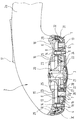
- the shower head shown comprises in a manner known per se a bell-shaped housing 2, the open, lower end of which is closed by a multi-part shower base 1.
- the shower base 1 is detachably fastened by means of a central screw 3 to the internals of the shower head accommodated within the housing 2 in a manner not of interest here.
- the shower base 1 in turn comprises a perforated plate 1 a made of a relatively rigid plastic material, which is covered on the outer surface, that is to say on the surface facing downwards in the drawing, with a shock protection plate 1 b made of relatively soft, elastic material.
- the impact protection plate 1b like all those components to be described, which consist of the same relatively soft, elastic plastic material, can be injection molded onto the perforated plate 1a using two-component technology.
- the impact protection plate 1b essentially covers the entire outer surface of the perforated plate 1a.
- the perforated plate 1 a of the shower base 1 has, in a manner known per se, a plurality of sets of through openings 4, 5 which are arranged on concentric circles around the central axis of the shower base 1 at regular angular intervals.
- the exact hole pattern which is formed by the through openings 4, 5 of the perforated plate 1a is without in the present context Matter.
- the through holes 5 of the perforated plate 1 a which are somewhat larger in diameter, are each penetrated by a hose-like nozzle insert 6 which has a relatively small axial length, that is to say only slightly protrudes the perforated plate 1 a on the upper side (facing the interior of the housing 2 of the shower head).
- the hose-like nozzle inserts 6 are each axially penetrated by a nozzle channel 7 of relatively large cross-section, which tapers conically towards the outside in the illustrated embodiment.
- the hose-like nozzle inserts 6 are also integrally formed on the impact protection plate 1b and are made of the same material as this.
- the passage openings 4 of the perforated plate 1a are each penetrated by hose-like nozzle inserts 8, which are integral with the impact protection plate 1b, but which have a greater axial length than the nozzle inserts 6, that is to say they protrude further on the inside of the perforated plate 1a.
- the hose-like nozzle inserts 8 are likewise each traversed by nozzle channels 9, which have a small cross section in comparison to the nozzle channels 7 of the nozzle inserts 6.
- the nozzle channels 9 also taper from the inside to the outside.
- the nozzle inserts 6 have a special shape, which there facilitates mechanical flexing by the user's sweeping hand in order to blow off limescale deposits in the nozzle channels 9, in particular in the vicinity of the water outlet openings 11. This shape is of minor importance in the present context and is therefore not described in detail.
- the axially shorter hose-like nozzle inserts 6 protrude into a first water space 13 formed inside the housing 2.
- the axially inner ends of the axially longer hose-like nozzle inserts 8, on the other hand, become received in through holes 14 of an inner partition 15, which is part of an insert 20 and separates the first water space 13 within the housing 2 from a second water space 16, which is at a greater distance from the shower base 1.
- the insert 20 also has a central bore 21 which runs coaxially to the central fastening screw 3 in the direction of the shower base 1.
- the central bore 21 is extended by an extension 22, which is delimited by an annular collar 23 on its circular outer circumference.
- the collar 23 lies with its annular end face on the top of the perforated plate 1a.
- an annular seal 25 is accommodated, which prevents the passage of air and / or water through the gap between the collar 23 and the perforated plate 1a.
- the groove 24 in the perforated plate 1a is connected to the outer surface of the perforated plate 1a via a plurality of axially parallel bores of relatively small diameter distributed over the circumference.
- the ring seal 25 is made of the same material as the shock protection plate 1b and the nozzle inserts 6 and 8. It is connected in one piece to the shock protection plate 1b via the holes 26 of the perforated plate 1a through material flags 33.
- the Perforated plate 1 a On a circle with a radius that is smaller than the radius of the collar 23 on the insert 20 is the Perforated plate 1 a is provided with a plurality of through bores 27 distributed over the circumference, which continue axially in corresponding through bores 28 of shock protection plate 1 b. Only one of these through holes 27 and 28 can be seen in the drawing.
- a second annular seal 29, which is also made of the same material as the shock protection plate 1b and the nozzle inserts 6 and 8, lies in a step 30 which is formed on the inside of the perforated plate 1a in its radially outermost region.
- the ring seal 29 is connected in one piece to the adjacent nozzle inserts 6 and 8 via a plurality of material lugs 31 distributed over the circumference of the shower base.
- the ring seal 29 seals three parts against one another: the perforated plate 1a, the insert 20 and the housing 2 of the shower head.
- the water flowing in in a known manner through the handle 2 a of the shower head is directed to the first water space 13 or to the second water space 16 by means of a changeover device which is operated via a rocker-shaped actuating member 17.
- the changeover device If the changeover device is such that the water reaches the first water space 13, it can exit from there via the nozzle channels 7 of the tubular nozzle inserts 6 and their outlet openings 10. Due to the relatively large diameter of the outlet openings 10, relatively slow water jets with a large diameter result, which are known as "soft jets". These water jets are also mixed with air in a manner not of interest here, which is sucked in through the through bores 27, 28 of the shower base 1 and the central bore 21 of the insert 20.
- the switching device is actuated by means of the rocker-shaped actuating member 17 in such a way that the water flowing in via the handle 2a reaches the second water space 16, then this water flows through the openings 14 in the partition 15 into the hose-like nozzle inserts 8 of the shower base 1.
- the water is greatly accelerated; it emerges from the openings 11 at high speed in the form of a relatively narrow jet.
- These water jets are therefore also called "hard jets”.
Abstract
Description
Die Erfindung betrifft einen Brausekopf, insbesondere für eine Handbrause, mit
- a) einem im wesentlichen glockenförmigen Gehäuse, in dem mindestens ein mit einem Wasserzulaufkanal verbindbarer Wasserraum ausgebildet ist;
- b) einem Brauseboden, welcher das glockenförmige Gehäuse nach unten abschließt und umfaßt:
- ba) eine Lochplatte aus starrem Material, die eine Vielzahl von Durchgangsbohrungen aufweist;
- bc) eine Vielzahl von schlauchartigen Düseneinsätzen, die aus verhältnismäßig weichem, elastischem Material bestehen, jeweils von einem in einer Wasseraustrittöffnung endenden Düsenkanal durchzogen sind und jeweils durch eine Durchgangsbohrung der Lochplatte hindurchgeführt sind,
- c) einer oder mehrerer Dichtungen, welche den Brauseboden gegen das Gehäuse und/oder einen oder mehrere im Gehäuse angeordneten Einsatz (Einsätze) abdichtet (abdichten).
- a) an essentially bell-shaped housing in which at least one water space which can be connected to a water inlet channel is formed;
- b) a shower base which closes off the bell-shaped housing and comprises:
- ba) a perforated plate made of rigid material, which has a plurality of through holes;
- bc) a multiplicity of hose-like nozzle inserts, which consist of relatively soft, elastic material, are each penetrated by a nozzle channel ending in a water outlet opening and are each passed through a through hole in the perforated plate,
- c) one or more seals which seal the shower base against the housing and / or one or more inserts arranged in the housing.
Es ist bekannt, daß die Wasseraustrittsöffnungen an Brauseböden dazu neigen, im Laufe der Nutzungsdauer des Brausekopfes zu verkalken. Dies äußert sich zunächst in einem Strahlbild, dessen Geometrie vom Neuzustand abweicht, sowie einer geringeren abgegebenen Literleistung. Die Kalkablagerungen können soweit fortschreiten, daß schließlich die Wasseraustrittsöffnungen vollständig verstopft sind.It is known that the water outlet openings on shower bases tend to calcify over the course of the service life of the shower head. This is first expressed in a spray pattern, the geometry of which is new deviates, as well as a lower liter output. The limescale deposits can progress to the point where the water outlet openings are completely blocked.
Aus diesem Grunde ist es z. B. aus dem DE-GM 90 17 978 oder dem DE-GM 93 03 986 bekannt, die Wasseraustrittsöffnungen an schlauchartigen Düseneinsätzen aus weichelastischem Material auszubilden. Diese können durch manuelles Überstreichen so mechanisch gewalkt werden, daß die an den Mantelflächen der Düsenkanäle, insbesondere im Bereich der Wasseraustrittsöffnungen, abgelagerten Kalkschichten abgesprengt werden. Der Wasserdurchfluß durch die Wasseraustrittsöffnungen im Brauseboden ist dann wieder frei.For this reason it is e.g. B. from DE-GM 90 17 978 or DE-GM 93 03 986 known to form the water outlet openings on hose-like nozzle inserts made of flexible material. These can be mechanically tumbled by manual painting so that the layers of lime deposited on the lateral surfaces of the nozzle channels, in particular in the area of the water outlet openings, are blasted off. The water flow through the water outlet openings in the shower base is then free again.
Die Abdichtung zwischen dem Brauseboden und dem glockenförmigen Gehäuse erfolgt in diesen Fällen durch O-Ringdichtungen, die als gesonderte Teile hergestellt und montiert werden. Sowohl durch die Herstellung als auch die Lagerhaltung und die Montage dieser gesonderten Dichtungen entstehen Kosten.In these cases, the seal between the shower base and the bell-shaped housing is made using O-ring seals, which are manufactured and assembled as separate parts. Costs arise from the manufacture, storage and assembly of these separate seals.
Aufgabe der vorliegenden Erfindung ist es, einen Brausekopf der eingangs genannten Art zu auszugestalten, daß die mit den Dichtungen, die zur Abdichtung des Brausebodens gegen den restlichen Brausekopf benötigt werden, verbundenen Kosten so niedrig wie möglich gehalten werden.The object of the present invention is to design a shower head of the type mentioned at the outset that the costs associated with the seals which are required for sealing the shower base against the rest of the shower head are kept as low as possible.
Diese Aufgabe wird erfindungsgemäß dadurch gelöst, daß
- d) die Dichtung(en) gemeinsam mit den Düseneinsätzen und aus demselben Material wie diese hergestellt ist (sind).
- d) the seal (s) are (are) made together with the nozzle inserts and from the same material as this.
Erfindungsgemäß sind also die Dichtungen, mit welchen der Brauseboden gegen den restlichen Brausekopf abgedichtet wird, keine gesonderten (Zuliefer-) Teile, die unabhängig von der Herstellung des Brausebodens angefertigt, auf Lager gehalten und dann bei der Endmontage des Brausekopfes zwischen Brauseboden und Gehäuse eingefügt werden. Vielmehr entstehen die Dichtungen bei der Herstellung des Brausebodens gewissermaßen fast ohne Kosten mit, wobei sie sich auch bereits schon an ihrem endgültigen Einsatzort befinden und deshalb einer gesonderten Lagerhaltung und Montage nicht mehr bedürfen. Auf diese Weise werden viele Handhabungsschritte, die beim Stande der Technik im Zusammenhang mit diesen Dichtungen noch erforderlich waren, eliminiert.According to the invention, the seals with which the shower base is sealed off from the rest of the shower head are not separate (supplier) parts which are manufactured independently of the manufacture of the shower base, kept in stock and then inserted between the shower base and the housing during the final assembly of the shower head . Rather, the seals in the manufacture of the shower base are made with almost no cost, although they are already in their final place of use and therefore no longer require separate storage and assembly. In this way, many handling steps that were still required in the prior art in connection with these seals are eliminated.
Herstellungstechnisch ist dabei diejenige Ausgestaltung der Erfindung besonders günstig, bei welcher die Dichtungen einstückig mit den Düseneinsätzen zusammenhängen.In terms of production technology, the embodiment of the invention in which the seals are connected in one piece to the nozzle inserts is particularly favorable.
Bei einer bevorzugten Ausführungsform wird der einstückige Zusammenhang dadurch hergestellt, daß zumindest eine Dichtung über mindestens eine Materialfahne, die sich an der Innenfläche der Lochplatte entlang erstreckt, mit mindestens einem Düseneinsatz verbunden ist. Die Materialfahne kann dabei in einer in der Innenfläche der Lochplatte eingeformten Nut angeordnet sein.In a preferred embodiment, the one-piece connection is established in that at least one seal is connected to at least one nozzle insert via at least one material vane that extends along the inner surface of the perforated plate. The material vane can be arranged in a groove formed in the inner surface of the perforated plate.
Bei einer sehr vorteilhaften Ausführungsform der Erfindung sind die Düseneinsätze einstückig mit einer Stoßschutzplatte ausgebildet, die im wesentlichen die ganze Außenfläche der Lochplatte abdeckt und aus demselben Material wie die Düseneinsätze besteht. Diese Stoßschutzplatte bildet, wie der Name bereits zum Ausdruck bringt, einen Stoßschutz der Außenfläche der Lochplatte, die ja selbst aus starrem Material besteht und selbst nicht so stoßbeständig ist. Auch diese Stoßschutzplatte läßt sich aufgrund der gemeinsamen Herstellung mit den Düseneinsätzen ohne nennenswerte zusätzliche Kosten verwirklichen.In a very advantageous embodiment of the invention, the nozzle inserts are formed in one piece with a shock protection plate which essentially covers the entire outer surface of the perforated plate and is made of the same material as the nozzle inserts. As the name suggests, this shock protection plate forms a shock protection for the outer surface of the perforated plate, which itself is made of rigid material and not itself is so shock resistant. This shock protection plate can also be realized without significant additional costs due to the joint production with the nozzle inserts.
Wird eine derartige Stoßschutzplatte verwendet, so ist auch eine Ausgestaltung der Erfindung in der Weise von Vorteil, daß die Dichtung über mindestens eine Materialfahne, die sich durch eine Bohrung in der Lochplatte hindurch erstreckt, mit der Stoßschutzplatte verbunden ist. Die Stoßschutzplatte, die ja auf der der Dichtung gegenüberliegenden Seite der Lochplatte angeordnet ist, läßt sich praktisch unabhängig von der jeweiligen Position der Dichtung durch die verbindende Bohrung in der Lochplatte immer auf kurzem Wege erreichen.If such a shock protection plate is used, an embodiment of the invention is also advantageous in that the seal is connected to the shock protection plate via at least one material lug which extends through a hole in the perforated plate. The impact protection plate, which is arranged on the side of the perforated plate opposite the seal, can practically always be reached in a short way through the connecting hole in the perforated plate, regardless of the respective position of the seal.
Im allgemeinen sind Brauseböden mit kreisförmigem Umfang versehen, weshalb auch die Dichtung zwischen Brauseboden und restlichem Brausekopf im allgemeinen als Ringdichtung ausgebildet ist. In diesen Fällen empfiehlt es sich, daß mehrere Materialfahnen über den Umfang der Dichtung verteilt vorgesehen sind. Diese Mehrzahl von Materialfahnen stellt einen guten Materialfluß beim Spritzen der Düseneinsätze, der Stoßschutzplatte und der Dichtungen sicher. Sie sorgen außerdem für einen guten Zusammenhalt der verschiedenen Komponenten des Brausebodens einschließlich der Dichtung(en), auch wenn das weichelastische Material nicht in zwei Komponententechnik an die starre Lochplatte angespritzt ist, also bereits aus diesem Grunde an der starren Lochplatte festgelegt ist.In general, shower bases are provided with a circular circumference, which is why the seal between the shower base and the rest of the shower head is generally designed as an annular seal. In these cases, it is advisable to provide several material flags distributed over the circumference of the seal. This plurality of material flags ensures a good flow of material when spraying the nozzle inserts, the shock protection plate and the seals. They also ensure good cohesion of the various components of the shower base, including the seal (s), even if the soft-elastic material is not molded onto the rigid perforated plate in two components, that is why it is already attached to the rigid perforated plate for this reason.
Selbstverständlich ist aber unabhängig hiervon das Anspritzen aller weichelastischer Komponenten an die starre Lochplatte in der bekannten Zweikomponententechnik im Rahmen der Erfindung möglich und von Vorteil.Of course, regardless of this, the injection of all soft elastic components onto the rigid perforated plate in the known two-component technology in Possible and advantageous within the scope of the invention.
Ein Ausführungsbeispiel der Erfindung wird nachfolgend anhand der Zeichnung näher erläutert; die einzige Figur zeigt die (Teil-)Seitenansicht eines Brausekopfes, teilweise im Schnitt.An embodiment of the invention is explained below with reference to the drawing; the only figure shows the (partial) side view of a shower head, partly in section.
Der dargestellte Brausekopf umfaßt in an und für sich bekannter Weise ein glockenförmiges Gehäuse 2, dessen offenes, unteres Ende durch einen mehrteiligen Brauseboden 1 abgeschlossen ist. Der Brauseboden 1 ist mittels einer zentralen Schraube 3 an den innerhalb des Gehäuses 2 untergebrachten Einbauten des Brausekopfes in hier nicht näher interessierender Weise lösbar befestigt.The shower head shown comprises in a manner known per se a bell-
Der Brauseboden 1 seinerseits umfaßt eine Lochplatte 1a aus verhältnismäßig starrem Kunststoffmaterial, die an der Außenfläche, also an der in der Zeichnung nach unten zeigenden Fläche, mit einer Stoßschutzplatte 1b aus verhältnismäßig weichem, elastischem Material abgedeckt ist. Die Stoßschutzplatte 1b kann ebenso wie alle diejenigen noch zu beschreibenden Komponenten, die aus demselben verhältnismäßig weichen, elastischen Kunststoffmaterial bestehen, in Zweikomponenten-Technik an die Lochplatte 1a angespritzt werden. Die Stoßschutzplatte 1b überdeckt im wesntlichen die gesamte Außenfläche der Lochplatte 1a.The shower base 1 in turn comprises a
Die Lochplatte 1a des Brausebodens 1 weist in an und für sich bekannter Weise mehrere Sätze von Durchgangsöffnungen 4, 5 auf, die auf konzentrischen Kreisen um die Mittelachse des Brausebodens 1 herum in regelmäßigen Winkelabständen angeordnet sind. Das genaue Lochmuster, welches von den Durchgangsöffnungen 4, 5 der Lochplatte 1a gebildet wird, ist im vorliegenden Zusammenhang ohne Belang.The
Die im Durchmesser etwas größeren Durchgangsöffnungen 5 der Lochplatte 1a werden jeweils von einem schlauchartigen Düseneinsatz 6 durchsetzt, der eine verhältnismäßig geringe axiale Länge aufweist, also die Lochplatte 1a an der oberen (zum Inneren des Gehäuses 2 des Brausekopfes gewandten) Seite nur geringfügig überragt. Die schlauchartigen Düseneinsätze 6 werden jeweils von einem Düsenkanal 7 verhältnismäßig großen Querschnittes axial durchsetzt, der sich beim dargestellten Ausführungsbeispiel zur Außenseite hin konisch verjüngt. Die schlauchartigen Düseneinsätze 6 sind zudem einstückig an die Stoßschutzplatte 1b angeformt und bestehen aus demselben Material wie diese.The through
Auch die Durchtrittsöffnungen 4 der Lochplatte 1a werden jeweils von schlauchartigen Düseneinsätzen 8 durchsetzt, die mit der Stoßschutzplatte 1b einstückig sind, die jedoch eine größere axiale Länge als die Düseneinsätze 6 besitzen, also auf der Innenseite der Lochplatte 1a weiter überstehen. Die schlauchartigen Düseneinsätze 8 werden ebenfalls jeweils von Düsenkanälen 9 durchzogen, die im Vergleich zu den Düsenkanälen 7 der Düseneinsätze 6 einen kleinen Querschnitt aufweisen. Auch die Düsenkanäle 9 verjüngen sich jeweils von innen nach außen.The
Am äußeren Ende besitzen die Düseneinsätze 6 eine spezielle Formgebung, welche dort ein mechanisches Walken durch die überstreichende Hand des Benutzers erleichtert, um Kalkablagerungen in den Düsenkanälen 9, insbesondere in der Nähe der Wasseraustrittsöffnungen 11, abzusprengen. Diese Formgebung ist im vorliegenden Zusammenhang von untergeordneter Bedeutung und wird daher nicht näher beschrieben.At the outer end, the
Wenn der Brauseboden 1, wie in der Zeichnung dargestellt, an dem Gehäuse 2 des Brausekopfes montiert ist, ragen die axial kürzeren schlauchartigen Düseneinsätze 6 in einen ersten innerhalb des Gehäuses 2 ausgebildeten Wasserraum 13. Die axial innenliegenden Enden der axial längeren schlauchartigen Düseneinsätze 8 dagegen werden in Durchgangsbohrungen 14 einer inneren Trennwand 15 aufgenommen, welche Teil eines Einsatzes 20 ist und den ersten Wasserraum 13 innerhalb des Gehäuses 2 von einem zweiten Wasserraum 16 trennt, der einen größeren Abstand von dem Brauseboden 1 aufweist.When the shower base 1, as shown in the drawing, is mounted on the
Der Einsatz 20 besitzt außerdem eine Mittelbohrung 21, die koaxial zu der zentralen Befestigungsschraube 3 in Richtung auf den Brauseboden 1 zu verläuft. In der Nähe des Brausebodens 1 ist die Mittelbohrung 21 durch eine Erweiterung 22 verlängert, die an ihrem kreisförmigen Außenumfang von einem ringförmigen Kragen 23 begrenzt ist. Der Kragen 23 liegt mit seiner ringförmigen Stirnfläche an der Oberseite der Lochplatte 1a an. In einer Nut 24 an der Oberseite der Lochplatte 1a ist eine Ringdichtung 25 untergebracht, welche den Durchgang von Luft und/oder Wasser durch den Spalt zwischen Kragen 23 und Lochplatte 1a verhindert. Die Nut 24 in der Lochplatte 1a steht über mehrere, über den Umfang verteilte achsparallele Bohrungen verhältnismäßig kleinen Durchmessers mit der Außenfläche der Lochplatte 1a in Verbindung. Die Ringdichtung 25 besteht aus demselben Material wie die Stoßschutzplatte 1b und die Düseneinsätze 6 und 8. Sie steht mit der Stoßschutzplatte 1b über die Bohrungen 26 der Lochplatte 1a durchdringende Materialfahnen 33 einstückig in Verbindung.The
Auf einem Kreis mit einem Radius, der kleiner als der Radius des Ringbundes 23 am Einsatz 20 ist, ist die Lochplatte 1a mit mehreren über den Umfang verteilten Durchgangsbohrungen 27 versehen, die sich in entsprechenden Durchgangsbohrungen 28 der Stoßschutzplatte 1b axial fortsetzen. Nur eine dieser Durchgangsbohrungen 27 bzw. 28 ist in der Zeichnung erkennbar.On a circle with a radius that is smaller than the radius of the
Eine zweite ringförmige Dichtung 29, die ebenfalls aus demselben Material wie die Stoßschutzplatte 1b und die Düseneinsätze 6 und 8 gefertigt ist, liegt in einer Stufe 30 ein, die an der Innenseite der Lochplatte 1a in deren radial äußerstem Bereich ausgeformt ist. Die Ringdichtung 29 steht über mehrere über den Umfang des Brausebodens hinweg verteilte Materialfahnen 31 mit den benachbarten Düseneinsätzen 6 bzw. 8 einstückig in Verbindung. Die Ringdichtung 29 dichtet drei Teile gegeneinander ab: die Lochplatte 1a, den Einsatz 20 sowie das Gehäuse 2 des Brausekopfes.A second
Aufgrund der einstückigen Verbindung aller aus demselben weichelastischen Material bestehenden Teile, insbesondere also auch aufgrund der Verbindung zwischen den Ringdichtungen 25, 29 und den Düseneinsätzen 6, 8 bzw. der Stoßschutzplatte 1b ist es möglich, die zur Abdichtung des Brausebodens 1 an dem restlichen Brausekopf erforderlichen Dichtungen bei der Herstellung des Brausebodens 1 selbst ohne besonderen Arbeitsgang mit anzufertigen und an der richtigen Stelle zu positionieren.Due to the one-piece connection of all parts made of the same soft elastic material, in particular also because of the connection between the ring seals 25, 29 and the nozzle inserts 6, 8 or the
Die Funktion des beschriebenen Brausekopfes ist wie folgt:The function of the shower head described is as follows:
Das in bekannter Weise durch den Handgriff 2a des Brausekopfes zufließende Wasser wird mittels einer Umstellvorrichtung, die über ein wippenförmiges Betätigungsorgan 17 bedient wird, wahlweise zum ersten Wasserraum 13 oder zum zweiten Wasserraum 16 geleitet.The water flowing in in a known manner through the
Steht die Umstellvorrichtung so, daß das Wasser in den ersten Wasserraum 13 gelangt, so kann es von dort über die Düsenkanäle 7 der schlauchförmigen Düseneinsätze 6 und deren Austrittsöffnungen 10 austreten. Aufgrund des verhältnismäßig großen Durchmessers der Austrittsöffnungen 10 ergeben sich verhältnismäßig langsame Wasserstrahlen mit großem Durchmesser, die als "Weichstrahlen" bekannt sind. Diese Wasserstrahlen werden zudem in hier nicht näher interessierender Weise mit Luft vermischt, welche über die Durchgangsbohrungen 27, 28 des Brausebodens 1 und die Mittelbohrung 21 des Einsatzes 20 angesaugt wird.If the changeover device is such that the water reaches the
Wenn mittels des wippenförmigen Betätigungsorganes 17 die Umstellvorrichtung so betätigt wird, daß das über den Handgriff 2a zuströmende Wasser in den zweiten Wasserraum 16 gelangt, so strömt dieses Wasser über die Durchtrittsöffnungen 14 der Trennwand 15 in die schlauchartigen Düseneinsätze 8 des Brausebodens 1 über. In den verhältnismäßig schmalen Düsenkanälen 9 der schlauchartigen Düseneinsätze 8, und insbesondere in deren sich konisch auf die Austrittsöffnung 11 zu verjüngenden Endbereichen wird das Wasser stark beschleunigt; es tritt in Form eines verhältnismäßig schmalen Strahles mit hoher Geschwindigkeit aus den Öffnungen 11 aus. Diese Wasserstrahlen werden daher auch "Hartstrahlen" genannt.If the switching device is actuated by means of the rocker-shaped
Claims (7)
Applications Claiming Priority (2)
| Application Number | Priority Date | Filing Date | Title |
|---|---|---|---|
| DE4447115 | 1994-12-29 | ||
| DE4447115A DE4447115C2 (en) | 1994-12-29 | 1994-12-29 | Shower head, especially for a hand shower |
Publications (3)
| Publication Number | Publication Date |
|---|---|
| EP0719587A2 true EP0719587A2 (en) | 1996-07-03 |
| EP0719587A3 EP0719587A3 (en) | 1998-02-11 |
| EP0719587B1 EP0719587B1 (en) | 2003-03-19 |
Family
ID=6537435
Family Applications (1)
| Application Number | Title | Priority Date | Filing Date |
|---|---|---|---|
| EP95119779A Expired - Lifetime EP0719587B1 (en) | 1994-12-29 | 1995-12-15 | Shower head, in particular for a hand-held shower |
Country Status (7)
| Country | Link |
|---|---|
| US (1) | US5702057A (en) |
| EP (1) | EP0719587B1 (en) |
| JP (1) | JP3866315B2 (en) |
| AT (1) | ATE234686T1 (en) |
| DE (1) | DE4447115C2 (en) |
| ES (1) | ES2193167T3 (en) |
| FI (1) | FI956162A (en) |
Cited By (5)
| Publication number | Priority date | Publication date | Assignee | Title |
|---|---|---|---|---|
| EP0885660A1 (en) * | 1997-06-20 | 1998-12-23 | H. Weidmann AG | Shower head |
| WO2000010720A1 (en) * | 1998-08-20 | 2000-03-02 | Ideal-Standard Gmbh | Shower head comprising nozzles moved on a displacement path |
| US7278591B2 (en) | 2004-08-13 | 2007-10-09 | Clearman Joseph H | Spray apparatus |
| US7770820B2 (en) | 2004-08-13 | 2010-08-10 | Moen Incorporated | Spray apparatus and dispensing tubes therefore |
| DE102012022115A1 (en) * | 2012-11-13 | 2014-05-15 | Neoperl Gmbh | aerator |
Families Citing this family (48)
| Publication number | Priority date | Publication date | Assignee | Title |
|---|---|---|---|---|
| GB2333251B (en) * | 1998-01-20 | 2001-09-12 | Aqualisa Products Ltd | Shower head |
| US6250572B1 (en) * | 2000-09-07 | 2001-06-26 | Globe Union Industrial Corp. | Showerhead |
| WO2002047765A1 (en) | 2000-12-12 | 2002-06-20 | Water Pik, Inc. | Shower head assembly |
| US7114666B2 (en) | 2002-12-10 | 2006-10-03 | Water Pik, Inc. | Dual massage shower head |
| USD485887S1 (en) | 2002-12-10 | 2004-01-27 | Water Pik, Inc. | Pan head style shower head |
| US7740186B2 (en) | 2004-09-01 | 2010-06-22 | Water Pik, Inc. | Drenching shower head |
| US7744021B2 (en) * | 2006-03-09 | 2010-06-29 | Belanger, Inc. | Carwash spray nozzle and washing system using same |
| WO2007124455A2 (en) | 2006-04-20 | 2007-11-01 | Water Pik, Inc. | Converging spray showerhead |
| US7789326B2 (en) | 2006-12-29 | 2010-09-07 | Water Pik, Inc. | Handheld showerhead with mode control and method of selecting a handheld showerhead mode |
| US8020787B2 (en) | 2006-11-29 | 2011-09-20 | Water Pik, Inc. | Showerhead system |
| US8794543B2 (en) | 2006-12-28 | 2014-08-05 | Water Pik, Inc. | Low-speed pulsating showerhead |
| US7770822B2 (en) | 2006-12-28 | 2010-08-10 | Water Pik, Inc. | Hand shower with an extendable handle |
| US8366024B2 (en) | 2006-12-28 | 2013-02-05 | Water Pik, Inc. | Low speed pulsating showerhead |
| US8371618B2 (en) | 2007-05-04 | 2013-02-12 | Water Pik, Inc. | Hidden pivot attachment for showers and method of making same |
| USD624156S1 (en) | 2008-04-30 | 2010-09-21 | Water Pik, Inc. | Pivot ball attachment |
| US8348181B2 (en) | 2008-09-15 | 2013-01-08 | Water Pik, Inc. | Shower assembly with radial mode changer |
| USD616061S1 (en) | 2008-09-29 | 2010-05-18 | Water Pik, Inc. | Showerhead assembly |
| USD625776S1 (en) | 2009-10-05 | 2010-10-19 | Water Pik, Inc. | Showerhead |
| US8616470B2 (en) | 2010-08-25 | 2013-12-31 | Water Pik, Inc. | Mode control valve in showerhead connector |
| CN102527528B (en) * | 2010-12-31 | 2014-03-12 | 厦门松霖科技有限公司 | Dismounting device for sprinkler |
| US9387495B2 (en) | 2011-05-20 | 2016-07-12 | Kohler Co. | Shower device |
| USD678467S1 (en) | 2012-01-27 | 2013-03-19 | Water Pik, Inc. | Ring-shaped handheld showerhead |
| USD678463S1 (en) | 2012-01-27 | 2013-03-19 | Water Pik, Inc. | Ring-shaped wall mount showerhead |
| USD692527S1 (en) | 2012-03-12 | 2013-10-29 | Kohler Co. | Shower faceplate |
| US9468939B2 (en) | 2012-03-12 | 2016-10-18 | Kohler Co. | Faceplate for shower device |
| CA2820623C (en) | 2012-06-22 | 2017-10-03 | Water Pik, Inc. | Bracket for showerhead with integral flow control |
| US9687859B2 (en) * | 2012-11-16 | 2017-06-27 | Kohler Co. | Shower device |
| CN102962147B (en) * | 2012-11-23 | 2016-09-07 | 厦门松霖科技有限公司 | Sprinkler with detachable surface cover |
| USD715896S1 (en) | 2013-03-15 | 2014-10-21 | Kohler Co. | Shower faceplate |
| USD716415S1 (en) | 2013-03-15 | 2014-10-28 | Kohler Co. | Shower faceplate |
| USD740917S1 (en) | 2013-03-16 | 2015-10-13 | Kohler Co. | Shower faceplate for shower device |
| EP3513879A1 (en) | 2013-06-13 | 2019-07-24 | Water Pik, Inc. | Showerhead with turbine driven shutter |
| USD744066S1 (en) | 2014-06-13 | 2015-11-24 | Water Pik, Inc. | Wall mount showerhead |
| USD744614S1 (en) | 2014-06-13 | 2015-12-01 | Water Pik, Inc. | Wall mount showerhead |
| USD744612S1 (en) | 2014-06-13 | 2015-12-01 | Water Pik, Inc. | Handheld showerhead |
| USD744064S1 (en) | 2014-06-13 | 2015-11-24 | Water Pik, Inc. | Handheld showerhead |
| USD745111S1 (en) | 2014-06-13 | 2015-12-08 | Water Pik, Inc. | Wall mount showerhead |
| USD744065S1 (en) | 2014-06-13 | 2015-11-24 | Water Pik, Inc. | Handheld showerhead |
| USD744611S1 (en) | 2014-06-13 | 2015-12-01 | Water Pik, Inc. | Handheld showerhead |
| CA3013213C (en) | 2016-02-01 | 2021-04-20 | Water Pik, Inc. | Handheld pet spray wand |
| USD803981S1 (en) | 2016-02-01 | 2017-11-28 | Water Pik, Inc. | Handheld spray nozzle |
| US10265710B2 (en) | 2016-04-15 | 2019-04-23 | Water Pik, Inc. | Showerhead with dual oscillating massage |
| USD970684S1 (en) | 2016-04-15 | 2022-11-22 | Water Pik, Inc. | Showerhead |
| US10441960B2 (en) | 2016-09-08 | 2019-10-15 | Water Pik, Inc. | Pause assembly for showerheads |
| USD843549S1 (en) | 2017-07-19 | 2019-03-19 | Water Pik, Inc. | Handheld spray nozzle |
| DE102018201183B3 (en) * | 2018-01-25 | 2019-01-31 | Hansgrohe Se | Shower jet generating device with pressure relief valve |
| USD872227S1 (en) | 2018-04-20 | 2020-01-07 | Water Pik, Inc. | Handheld spray device |
| US11221085B1 (en) * | 2019-06-28 | 2022-01-11 | T&S Brass And Bronze Works, Inc. | Pre-rinse spray valve |
Citations (2)
| Publication number | Priority date | Publication date | Assignee | Title |
|---|---|---|---|---|
| DE9017978U1 (en) | 1989-12-28 | 1993-06-03 | Friedrich Grohe Ag, 5870 Hemer, De | |
| DE9303986U1 (en) | 1992-11-04 | 1993-08-12 | Friedrich Grohe Ag, 58675 Hemer, De |
Family Cites Families (6)
| Publication number | Priority date | Publication date | Assignee | Title |
|---|---|---|---|---|
| US2402741A (en) * | 1944-10-03 | 1946-06-25 | Adolphe O Draviner | Spray head |
| US2559894A (en) * | 1948-02-25 | 1951-07-10 | Carl H Nordell | Shower head |
| DE3413552A1 (en) * | 1984-04-11 | 1985-10-24 | Hansa Metallwerke Ag, 7000 Stuttgart | SHOWER |
| US5228625A (en) * | 1990-02-22 | 1993-07-20 | Masco Gmbh | Sprinkler head |
| DE4106183A1 (en) * | 1991-02-27 | 1992-09-03 | Standard Elektrik Lorenz Ag | DEVICE AND METHOD FOR D-CHANNEL PACKAGING |
| JPH06262101A (en) * | 1992-11-04 | 1994-09-20 | Friedrich Grohe Ag | Shower head |
-
1994
- 1994-12-29 DE DE4447115A patent/DE4447115C2/en not_active Expired - Fee Related
-
1995
- 1995-12-15 AT AT95119779T patent/ATE234686T1/en active
- 1995-12-15 ES ES95119779T patent/ES2193167T3/en not_active Expired - Lifetime
- 1995-12-15 EP EP95119779A patent/EP0719587B1/en not_active Expired - Lifetime
- 1995-12-19 US US08/576,432 patent/US5702057A/en not_active Expired - Fee Related
- 1995-12-21 FI FI956162A patent/FI956162A/en unknown
- 1995-12-28 JP JP34372295A patent/JP3866315B2/en not_active Expired - Fee Related
Patent Citations (2)
| Publication number | Priority date | Publication date | Assignee | Title |
|---|---|---|---|---|
| DE9017978U1 (en) | 1989-12-28 | 1993-06-03 | Friedrich Grohe Ag, 5870 Hemer, De | |
| DE9303986U1 (en) | 1992-11-04 | 1993-08-12 | Friedrich Grohe Ag, 58675 Hemer, De |
Cited By (6)
| Publication number | Priority date | Publication date | Assignee | Title |
|---|---|---|---|---|
| EP0885660A1 (en) * | 1997-06-20 | 1998-12-23 | H. Weidmann AG | Shower head |
| WO2000010720A1 (en) * | 1998-08-20 | 2000-03-02 | Ideal-Standard Gmbh | Shower head comprising nozzles moved on a displacement path |
| US7278591B2 (en) | 2004-08-13 | 2007-10-09 | Clearman Joseph H | Spray apparatus |
| US7770820B2 (en) | 2004-08-13 | 2010-08-10 | Moen Incorporated | Spray apparatus and dispensing tubes therefore |
| DE102012022115A1 (en) * | 2012-11-13 | 2014-05-15 | Neoperl Gmbh | aerator |
| DE102012022115B4 (en) * | 2012-11-13 | 2014-10-30 | Neoperl Gmbh | aerator |
Also Published As
| Publication number | Publication date |
|---|---|
| FI956162A0 (en) | 1995-12-21 |
| JPH08229436A (en) | 1996-09-10 |
| EP0719587B1 (en) | 2003-03-19 |
| DE4447115A1 (en) | 1996-11-21 |
| ES2193167T3 (en) | 2003-11-01 |
| ATE234686T1 (en) | 2003-04-15 |
| US5702057A (en) | 1997-12-30 |
| EP0719587A3 (en) | 1998-02-11 |
| FI956162A (en) | 1996-06-30 |
| JP3866315B2 (en) | 2007-01-10 |
| DE4447115C2 (en) | 1998-11-19 |
Similar Documents
| Publication | Publication Date | Title |
|---|---|---|
| EP0719587B1 (en) | Shower head, in particular for a hand-held shower | |
| DE3509602C2 (en) | ||
| EP0719588B1 (en) | Shower head, in particular for a hand-held shower | |
| DE4447112C2 (en) | Shower head | |
| EP0719586B1 (en) | Shower head | |
| DE19830801C2 (en) | Device for ejecting liquid | |
| DE2904127C2 (en) | ||
| DE3513587A1 (en) | Spray nozzle in particular for spray guns | |
| EP0974399A1 (en) | Rotor nozzle | |
| EP2091657A1 (en) | Centrifuge, especially separator, with solid discharge orifices | |
| EP2620226A1 (en) | Container cleaning device | |
| DE2431513C3 (en) | Fluid dispensing device operating with a throttling effect | |
| DE19642055A1 (en) | Water jet regulator for water taps | |
| CH621057A5 (en) | ||
| DE4312994C2 (en) | Device for spraying suspensions, in particular mortars | |
| DE4224497A1 (en) | Mouthpiece for dispensing devices that are used to dispense two-component materials | |
| EP0841096B1 (en) | Shower head with cleaning device | |
| DE3841123A1 (en) | Nozzle mixing body for dry concrete spraying in the form of a connection stub | |
| DE3919546C2 (en) | ||
| WO2014030055A1 (en) | Housing for a radial fan with a pressure measurement channel integrated in the fan inlet | |
| EP0253388B1 (en) | Control device for field spraying conduits | |
| EP0901837B1 (en) | Shower head with pin descaler | |
| WO2020089171A1 (en) | Injection nozzle | |
| DE2621810C3 (en) | Foam gun for generating a multi-component foam in the low-pressure process | |
| EP0696680B1 (en) | Gear pump for the delivery of lacquer |
Legal Events
| Date | Code | Title | Description |
|---|---|---|---|
| PUAI | Public reference made under article 153(3) epc to a published international application that has entered the european phase |
Free format text: ORIGINAL CODE: 0009012 |
|
| AK | Designated contracting states |
Kind code of ref document: A2 Designated state(s): AT CH ES FR GB IT LI |
|
| PUAL | Search report despatched |
Free format text: ORIGINAL CODE: 0009013 |
|
| AK | Designated contracting states |
Kind code of ref document: A3 Designated state(s): AT CH ES FR GB IT LI |
|
| 17P | Request for examination filed |
Effective date: 19980321 |
|
| 17Q | First examination report despatched |
Effective date: 20000817 |
|
| GRAH | Despatch of communication of intention to grant a patent |
Free format text: ORIGINAL CODE: EPIDOS IGRA |
|
| GRAH | Despatch of communication of intention to grant a patent |
Free format text: ORIGINAL CODE: EPIDOS IGRA |
|
| GRAA | (expected) grant |
Free format text: ORIGINAL CODE: 0009210 |
|
| AK | Designated contracting states |
Designated state(s): AT CH ES FR GB IT LI |
|
| PG25 | Lapsed in a contracting state [announced via postgrant information from national office to epo] |
Ref country code: IT Free format text: LAPSE BECAUSE OF FAILURE TO SUBMIT A TRANSLATION OF THE DESCRIPTION OR TO PAY THE FEE WITHIN THE PRESCRIBED TIME-LIMIT;WARNING: LAPSES OF ITALIAN PATENTS WITH EFFECTIVE DATE BEFORE 2007 MAY HAVE OCCURRED AT ANY TIME BEFORE 2007. THE CORRECT EFFECTIVE DATE MAY BE DIFFERENT FROM THE ONE RECORDED. Effective date: 20030319 Ref country code: GB Free format text: LAPSE BECAUSE OF FAILURE TO SUBMIT A TRANSLATION OF THE DESCRIPTION OR TO PAY THE FEE WITHIN THE PRESCRIBED TIME-LIMIT Effective date: 20030319 |
|
| REG | Reference to a national code |
Ref country code: GB Ref legal event code: FG4D Free format text: NOT ENGLISH |
|
| REG | Reference to a national code |
Ref country code: CH Ref legal event code: EP |
|
| REG | Reference to a national code |
Ref country code: CH Ref legal event code: NV Representative=s name: FREI PATENTANWALTSBUERO |
|
| GBV | Gb: ep patent (uk) treated as always having been void in accordance with gb section 77(7)/1977 [no translation filed] |
Effective date: 20030319 |
|
| REG | Reference to a national code |
Ref country code: ES Ref legal event code: FG2A Ref document number: 2193167 Country of ref document: ES Kind code of ref document: T3 |
|
| ET | Fr: translation filed | ||
| PLBE | No opposition filed within time limit |
Free format text: ORIGINAL CODE: 0009261 |
|
| STAA | Information on the status of an ep patent application or granted ep patent |
Free format text: STATUS: NO OPPOSITION FILED WITHIN TIME LIMIT |
|
| 26N | No opposition filed |
Effective date: 20031222 |
|
| PGFP | Annual fee paid to national office [announced via postgrant information from national office to epo] |
Ref country code: AT Payment date: 20101228 Year of fee payment: 16 |
|
| PGFP | Annual fee paid to national office [announced via postgrant information from national office to epo] |
Ref country code: CH Payment date: 20111223 Year of fee payment: 17 Ref country code: FR Payment date: 20120104 Year of fee payment: 17 Ref country code: ES Payment date: 20111220 Year of fee payment: 17 |
|
| REG | Reference to a national code |
Ref country code: CH Ref legal event code: PL |
|
| REG | Reference to a national code |
Ref country code: AT Ref legal event code: MM01 Ref document number: 234686 Country of ref document: AT Kind code of ref document: T Effective date: 20121215 |
|
| REG | Reference to a national code |
Ref country code: FR Ref legal event code: ST Effective date: 20130830 |
|
| PG25 | Lapsed in a contracting state [announced via postgrant information from national office to epo] |
Ref country code: LI Free format text: LAPSE BECAUSE OF NON-PAYMENT OF DUE FEES Effective date: 20121231 Ref country code: CH Free format text: LAPSE BECAUSE OF NON-PAYMENT OF DUE FEES Effective date: 20121231 Ref country code: AT Free format text: LAPSE BECAUSE OF NON-PAYMENT OF DUE FEES Effective date: 20121215 |
|
| PG25 | Lapsed in a contracting state [announced via postgrant information from national office to epo] |
Ref country code: FR Free format text: LAPSE BECAUSE OF NON-PAYMENT OF DUE FEES Effective date: 20130102 |
|
| REG | Reference to a national code |
Ref country code: ES Ref legal event code: FD2A Effective date: 20140307 |
|
| PG25 | Lapsed in a contracting state [announced via postgrant information from national office to epo] |
Ref country code: ES Free format text: LAPSE BECAUSE OF NON-PAYMENT OF DUE FEES Effective date: 20121216 |