EP0719606B1 - A Method of manufacturing metallic slurry for casting - Google Patents
A Method of manufacturing metallic slurry for casting Download PDFInfo
- Publication number
- EP0719606B1 EP0719606B1 EP95309498A EP95309498A EP0719606B1 EP 0719606 B1 EP0719606 B1 EP 0719606B1 EP 95309498 A EP95309498 A EP 95309498A EP 95309498 A EP95309498 A EP 95309498A EP 0719606 B1 EP0719606 B1 EP 0719606B1
- Authority
- EP
- European Patent Office
- Prior art keywords
- molten metal
- cooling unit
- semi
- temperature
- metallic slurry
- Prior art date
- Legal status (The legal status is an assumption and is not a legal conclusion. Google has not performed a legal analysis and makes no representation as to the accuracy of the status listed.)
- Expired - Lifetime
Links
Images

Classifications
-
- B—PERFORMING OPERATIONS; TRANSPORTING
- B22—CASTING; POWDER METALLURGY
- B22D—CASTING OF METALS; CASTING OF OTHER SUBSTANCES BY THE SAME PROCESSES OR DEVICES
- B22D1/00—Treatment of fused masses in the ladle or the supply runners before casting
-
- C—CHEMISTRY; METALLURGY
- C22—METALLURGY; FERROUS OR NON-FERROUS ALLOYS; TREATMENT OF ALLOYS OR NON-FERROUS METALS
- C22C—ALLOYS
- C22C1/00—Making non-ferrous alloys
- C22C1/12—Making non-ferrous alloys by processing in a semi-solid state, e.g. holding the alloy in the solid-liquid phase
-
- Y—GENERAL TAGGING OF NEW TECHNOLOGICAL DEVELOPMENTS; GENERAL TAGGING OF CROSS-SECTIONAL TECHNOLOGIES SPANNING OVER SEVERAL SECTIONS OF THE IPC; TECHNICAL SUBJECTS COVERED BY FORMER USPC CROSS-REFERENCE ART COLLECTIONS [XRACs] AND DIGESTS
- Y10—TECHNICAL SUBJECTS COVERED BY FORMER USPC
- Y10S—TECHNICAL SUBJECTS COVERED BY FORMER USPC CROSS-REFERENCE ART COLLECTIONS [XRACs] AND DIGESTS
- Y10S164/00—Metal founding
- Y10S164/90—Rheo-casting
Definitions
- This invention relates to a method of manufacturing metallic slurry for casting. More precisely, it relates to a method of manufacturing metallic slurry for casting, including metallic slurry for Rheocasting and metallic slurry for casting billets for Thixocasting, which is semi-solidified metallic slurry in which metal in a molten state (liquid phase) and metal in a solid state (solid phase) coexist and fine grains are mixed with liquid.
- This kind of metallic slurry needs to be maintained in a state in which primary grains are separated from each other (by liquid matrix), and their crystal grains must be fine, homogeneous and non-dendritic, desirably globular.
- Slurry itself in such a state, or billet made by continuous casting and rapid cooling of the slurry and reheated becomes semi-molten metal of a high fraction solid and low viscosity, which can restrain shrinkage porosities in a casting and also improve its mechanical properties.
- the object of this invention is to obtain metallic slurry for casting, particularly of aluminium alloys, and to offer a method of manufacturing such slurry by which fine, homogeneous non-dendritic (globular) crystal grains can be obtained by means of simple facilities without requiring a complex process.
- a method of manufacturing metallic slurry for casting comprising rapidly cooling at least a portion of molten metal into a semi-solid state containing primary grains by putting the molten metal in contact with a cooling unit, and from the cooling unit passing the semi-solid metal into a holding furnace, characterised in that the molten metal in semi-solid state is held within a semi-molten temperature zone for a given time, before being used for casting, to enable the primary grains to grow and stabilize in globular form.
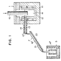
- Figure 1 is a schematic diagram showing an example of embodiment of this invention.
- Figure 2 is a microscopic picture of the structure of molten metal m' of which a portion has been quenched into a semi-solid state relating to an example of embodiment of this invention.
- Figure 3 is a microscopic picture of the structure of metallic slurry relating to an example of embodiment of this invention.
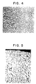
- Figure 4 is a microscopic picture of a billet made from metallic slurry related to an example of embodiment of this invention.
- Figure 5 is a microscopic picture of the structure of molten metal a portion of which was quenched into a semi-solid state for comparison purpose.
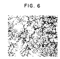
- Figure 6 is a microscopic picture of the structure of metallic slurry for comparison purpose.
- numbers 1, 2 and 3 denote molten metal discharge furnace, cooling unit, and holding furnace, respectively.
- the molten metal discharge furnace 1 is a furnace for accommodating and holding molten metal m of an aluminum alloy at a given temperature, or preferably at a temperature near the liquidus temperature, and it is composed of a well-known electric furnace 11 with a graphite crucible 12 inside, and a discharge feed pipe 14 equipped with a heater 13 and connected to the side thereof.
- Number 15 is a control rod to regulate the amount of discharged metal.
- the cooling unit 2 is for rapidly cooling a portion of the molten metal m poured from the molten metal discharge furnace 1 into a semi-solid state by contact with the molten metal. It is made of a material, such as copper plate coated with solution resistant material, in the shape of a flat and smooth plate, or a gutter (split cylinder), or a pipe (cylinder), located directly under the feed hole 14' of the discharge feed pipe 14 in a sloping position to allow molten metal m to flow down, and providing an inclined passage 21 on its surface where molten metal m is poured to flow.
- a material such as copper plate coated with solution resistant material, in the shape of a flat and smooth plate, or a gutter (split cylinder), or a pipe (cylinder), located directly under the feed hole 14' of the discharge feed pipe 14 in a sloping position to allow molten metal m to flow down, and providing an inclined passage 21 on its surface where molten metal m is poured to flow.
- Number 22 in the figure is a cooling pipe to circulate a coolant, such as water, to control and maintain the surface of the cooling unit 2 at a given temperature.
- a coolant such as water
- the surface temperature of the cooling unit 2, or the inclined passage 21, is controlled depending on the pouring temperature and flow rate, etc. of molten m to prevent it from flowing to the holding furnace 3 without creating a semi-solid state, or otherwise to prevent it from stagnating as it freezes.
- the temperature of molten metal m' before being held in the holding furnace 3, and at least a portion of which has been rapidly cooled into a semi-solid state by contacting the cooling unit 2 is controlled with the cooling unit 2 between (T L -T S )/2+ T S (T S denotes solidus temperature) and T L +40° C.
- T S denotes solidus temperature
- the temperature of molten metal m at the same time it contacts the inclined passage 21 of the cooling unit 2 is adjusted between liquidus T L and T L +60° C.
- T L liquidus
- T L +60° C it is difficult to control the cooling unit 2 and prevent molten metal m' from ceasing to flow on the inclined passage 21 of the cooling unit 2.
- T L +60° C it is also difficult to keep the semi-solid state of a portion of molten metal m' which has been put into contact with the surface of the inclined passage 21 of the cooling unit 2.
- the holding furnace 3 is for getting the primary grains to grow and stabilizing the globularized state of molten metal m' at least a portion of which is in a semi-solid state, or has crystallized primary grains, by holding the molten metal m' at solid-liquid coexisting temperature for a given time.
- a well-known electric furnace is used for the holding furnace 3.
- the holding time in the semi-molten metal temperature zone ( T S ⁇ T L ) in the holding furnace 3 is desirably 15 seconds or more; with an increase in the holding time, metallic slurry with more stabilized state of globularization was obtained.
- Aluminum alloy AC4C of JIS was used for molten metal m, and the molten metal temperature at the time of contact with the surface of the inclined passage 21 of the cooling unit 2 and the temperature of molten metal m' a portion of which was rapidly cooled into a semi-solid state were set at 644° C (liquidus temperature + 30° C) and 634° C (liquidus temperature + 20° C) respectively.
- the obtained molten metal m' a portion of which had been rapidly cooled into a state of semi-solid state was plunged into ice water and quenched.
- a microscopic picture of the structure of the metal is shown in Figure 2.
- the white section is primary grains. If molten metal does not contact the cooling unit 2, the structure becomes fine-grained, but dendritic. It is observed that the molten-metal which contacted the cooling unit 2 forred a granular structure.
- the primary grains have grown in good, globular crystals.
- the white section was the primary grains (solid phase) when the metal was in slurry, and the black section was the molten portion when the metal was in slurry. This applies to the following microscopic pictures of retal structures.
- Metallic slurry m" was obtained by using the same molten metal as in the above-mentioned embodiment, but the temperature of molten metal at the time of contacting the surface of the inclined passace 21 of the cooling unit 2 was 684° C (liquidus temperature +70 ° C) and the temperature of molten metal m' a portion of which had been rapidly cooled into a semi-solid state was 654° C (liquidus temperature + 40° C), and was held it in the holding furnace 3 at 577° C for one minute.
- Figure 5 and 6 show microscopic pictures of the structures of the molten metal m' a portion of which had been rapidly cooled into a semi-solid state and the metallic slurry m", which were both obtained under the above setting, and plunged into ice water and quenched as in the foregoing embodiment.
Description
- This invention relates to a method of manufacturing metallic slurry for casting. More precisely, it relates to a method of manufacturing metallic slurry for casting, including metallic slurry for Rheocasting and metallic slurry for casting billets for Thixocasting, which is semi-solidified metallic slurry in which metal in a molten state (liquid phase) and metal in a solid state (solid phase) coexist and fine grains are mixed with liquid.
- This kind of metallic slurry needs to be maintained in a state in which primary grains are separated from each other (by liquid matrix), and their crystal grains must be fine, homogeneous and non-dendritic, desirably globular. Slurry itself in such a state, or billet made by continuous casting and rapid cooling of the slurry and reheated becomes semi-molten metal of a high fraction solid and low viscosity, which can restrain shrinkage porosities in a casting and also improve its mechanical properties.
- Various attempts have been offered for this reason.
- A technique close to this invention was published in Japanese Patent Laid-Open No Sho61-235047.
- In the conventional technique, molten metal was poured on a temperature-controlled, inclined plate to produce a semi-molten metallic slurry as it flowed down the plate. However, the crystal grains became rosaceous and could not be satisfactorily globularized.
- It is also known from European Patent Application No 0392998 to produce semi-liquid aluminium, by melting the aluminium in a furnace, followed by pouring it down an inclined plate 2, and collecting it in a collecting vessel to producing aluminium which has a globular structure.
- However, the prior specification does not give any information as to what happens to the mass issuing from the cooling unit.
- The object of this invention is to obtain metallic slurry for casting, particularly of aluminium alloys, and to offer a method of manufacturing such slurry by which fine, homogeneous non-dendritic (globular) crystal grains can be obtained by means of simple facilities without requiring a complex process.
- According to the invention there is provided a method of manufacturing metallic slurry for casting comprising rapidly cooling at least a portion of molten metal into a semi-solid state containing primary grains by putting the molten metal in contact with a cooling unit, and from the cooling unit passing the semi-solid metal into a holding furnace, characterised in that the molten metal in semi-solid state is held within a semi-molten temperature zone for a given time, before being used for casting, to enable the primary grains to grow and stabilize in globular form.
- It is also characterised desirably by the adjustment of the temperature of the molten metal contacting the cooling unit between liquidus temperature TL and TL +60°C, and also by the setting of the temperature of the molten metal at least a portion of which has been rapidly cooled into a semi-solid state between (TL -TS )/2+ TS (TS represents solidus temperature) and TL +40 ° C.
Further, it is characterized by an arrangement to make at least a portion of the molten metal contact a cooling unit by pouring and letting the molten flow on the cooling unit, which specifically is an inclined passage on which molten metal is poured and let to flow down, and the inclined passage is made in the shape of a plate, or qutter, or pipe. - Figure 1 is a schematic diagram showing an example of embodiment of this invention.
- Figure 2 is a microscopic picture of the structure of molten metal m' of which a portion has been quenched into a semi-solid state relating to an example of embodiment of this invention.
- Figure 3 is a microscopic picture of the structure of metallic slurry relating to an example of embodiment of this invention.
- Figure 4 is a microscopic picture of a billet made from metallic slurry related to an example of embodiment of this invention.
- Figure 5 is a microscopic picture of the structure of molten metal a portion of which was quenched into a semi-solid state for comparison purpose.
- Figure 6 is a microscopic picture of the structure of metallic slurry for comparison purpose.
- The method of manufacturing metallic slurry for casting which relates to this invention is described below with reference to the (schematic) shown in Figure 1. This invention, however, is not limited to (such an embodiment).
- In the figure,
numbers 1, 2 and 3 denote molten metal discharge furnace, cooling unit, and holding furnace, respectively. - The molten metal discharge furnace 1 is a furnace for accommodating and holding molten metal m of an aluminum alloy at a given temperature, or preferably at a temperature near the liquidus temperature, and it is composed of a well-known electric furnace 11 with a
graphite crucible 12 inside, and adischarge feed pipe 14 equipped with aheater 13 and connected to the side thereof.Number 15 is a control rod to regulate the amount of discharged metal. - The cooling unit 2 is for rapidly cooling a portion of the molten metal m poured from the molten metal discharge furnace 1 into a semi-solid state by contact with the molten metal. It is made of a material, such as copper plate coated with solution resistant material, in the shape of a flat and smooth plate, or a gutter (split cylinder), or a pipe (cylinder), located directly under the feed hole 14' of the
discharge feed pipe 14 in a sloping position to allow molten metal m to flow down, and providing aninclined passage 21 on its surface where molten metal m is poured to flow. - Number 22 in the figure is a cooling pipe to circulate a coolant, such as water, to control and maintain the surface of the cooling unit 2 at a given temperature.
- The surface temperature of the cooling unit 2, or the
inclined passage 21, is controlled depending on the pouring temperature and flow rate, etc. of molten m to prevent it from flowing to theholding furnace 3 without creating a semi-solid state, or otherwise to prevent it from stagnating as it freezes. - Specifically, the temperature of molten metal m' before being held in the
holding furnace 3, and at least a portion of which has been rapidly cooled into a semi-solid state by contacting the cooling unit 2, is controlled with the cooling unit 2 between (TL -TS )/2+ TS (TS denotes solidus temperature) and TL +40° C. In this connection, if the temperature of molten metal is lower than ( TL -TS )/2+ TS , the molten metal portion of which has been rapidly cooled into a semi-solid state ceases to flow on the cooling unit 2. If it becomes higher than TL +40° C, the structure of metal m' held in theholding furnace 3 ends up as an undesirable structure which has grown dendritically. - By controlling the temperature of molten metal m' rapidly cooled by contact with the cooling unit 2 between (TL -TS )/2+ TS and TL +40° C, the structure of the molten metal m' when plunged into ice water (or the like) and quenched becomes a very fine, granular structure even at liquids TL + α (α below 40 degree C), whereas it was confirmed in an experiment that at the same (liquidus + α ) the structure of molten metal not contacting the cooling unit 2 does not become granular, but fine, dendritic when plunged into ice water or the like and quenched at the same liquidus TL + α .
- In this invention, the temperature of molten metal m at the same time it contacts the
inclined passage 21 of the cooling unit 2 is adjusted between liquidus TL and TL +60° C. When the temperature of molten metal m is below liquidus TL , it is difficult to control the cooling unit 2 and prevent molten metal m' from ceasing to flow on theinclined passage 21 of the cooling unit 2. When it is above TL +60° C, it is also difficult to keep the semi-solid state of a portion of molten metal m' which has been put into contact with the surface of theinclined passage 21 of the cooling unit 2. - The
holding furnace 3 is for getting the primary grains to grow and stabilizing the globularized state of molten metal m' at least a portion of which is in a semi-solid state, or has crystallized primary grains, by holding the molten metal m' at solid-liquid coexisting temperature for a given time. - For instance, a well-known electric furnace is used for the
holding furnace 3. - When molten metal m in the molten metal discharge furnace 1 is poured through the
discharge feed pipe 13 and let to flow down theinclined passage 21 of the cooling unit 2 after the molten metal temperature is adjusted between liquidus temperatures TL and TL +60° C, at least a portion of the molten metal m is rapidly cooled into a semi-solid state. And when the temperature of the molten metal m' rapidly cooled into a semi-solid state is controlled between ( TL -TS ) /2+ TS and TL +40° C, by means of the cooling unit 2 and the molten metal is held in theholding furnace 3 within the semi-molten temperature zone (TS ∼ TL ) for a given time, good metallic slurry m" with globular primary grains is obtained. - In an experiment, it was found that the holding time in the semi-molten metal temperature zone ( TS ∼ TL ) in the
holding furnace 3 is desirably 15 seconds or more; with an increase in the holding time, metallic slurry with more stabilized state of globularization was obtained. - Aluminum alloy AC4C of JIS was used for molten metal m, and the molten metal temperature at the time of contact with the surface of the
inclined passage 21 of the cooling unit 2 and the temperature of molten metal m' a portion of which was rapidly cooled into a semi-solid state were set at 644° C (liquidus temperature + 30° C) and 634° C (liquidus temperature + 20° C) respectively. The obtained molten metal m' a portion of which had been rapidly cooled into a state of semi-solid state was plunged into ice water and quenched. A microscopic picture of the structure of the metal is shown in Figure 2. - In this microscopic picture, the white section is primary grains. If molten metal does not contact the cooling unit 2, the structure becomes fine-grained, but dendritic. It is observed that the molten-metal which contacted the cooling unit 2 forred a granular structure.
- By holding the molten metal m' in the holding furnace at 577 ° c for one minute, metallic slurry m" was obtained. A microscopic picture of the structure of the metallic slurry m" after being plunged into ice water and quenched is shown in Figure 3.
- It is observed in this microscopic picture that the primary grains have grown in good, globular crystals. In the same picture, the white section was the primary grains (solid phase) when the metal was in slurry, and the black section was the molten portion when the metal was in slurry. This applies to the following microscopic pictures of retal structures.
- For reference sake, a microscopic picture of the structure of a billet which was made by continuous casting of the metallic slurry m" is shown in Figure 4. It is observed in this picture that the primary grains consist of good, globular crystals.
- Metallic slurry m" was obtained by using the same molten metal as in the above-mentioned embodiment, but the temperature of molten metal at the time of contacting the surface of the
inclined passace 21 of the cooling unit 2 was 684° C (liquidus temperature +70 ° C) and the temperature of molten metal m' a portion of which had been rapidly cooled into a semi-solid state was 654° C (liquidus temperature + 40° C), and was held it in theholding furnace 3 at 577° C for one minute. - Figure 5 and 6 show microscopic pictures of the structures of the molten metal m' a portion of which had been rapidly cooled into a semi-solid state and the metallic slurry m", which were both obtained under the above setting, and plunged into ice water and quenched as in the foregoing embodiment.
- It can be seen from these microscopic pictures that primary grains have grown in dendritic crystals.
- As described above, with the method relating to this invention of manufacturing metallic slurry for casting, fine-grained, nearly homogeneous non-dendritic (globular) primary grains can be obtained without the need of a complex process but with simple facilities.
- Having described specific preferred embodiments of the invention with reference to the accompanying drawings, it will be appreciated that the present invention is not limited to those precise embodiments, and that various changes and modifications can be effected therein by one of ordinary skill in the art without departing from the scope and spirit of the invention as defined by the appended claims.
- Also, it should be noted that although the specification is directed towards the creation of semi-molton metal slurries consisting of aluminium alloys, it is possible that other liquid alloys and elemental metal liquids may be used. In such cases the temperatures of the molten metal and of the cooling unit necessary to put the invention into practice are as prescribed in the specification for aluminium alloys.
Claims (6)
- A method of manufacturing metallic slurry for casting comprising rapidly cooling at least a portion of molten metal (m') into a semi-solid state containing primary grains by putting the molten metal (m) in contact with a cooling unit, and from the cooling unit passing the semi-solid metal (m') into a holding furnace (3), characterised in that the molten metal (m") in semi-solid state is held within a semi-molten temperature zone for a given time, before being used for casting, to enable the primary grains to grow and stabilize in globular form.
- A method of manufacturing metallic slurry for casting described in Claim (1) characterized by the adjustment of the temperature of the molten metal (m') contacting the cooling unit between liquidus temperatures TL and TL +60°C.
- A method of manufacturing metallic slurry for casting described in Claim (1) characterized by the setting of the temperature of the molten metal (m') at least a portion of which has been rapidly cooled into a semi-solid state between (TL -TS)/2+ TS, whereby TS represents a solidus temperature, and TL +40°C.
- A method of manufacturing metallic slurry for casting described in Claim (1) characterized by making at least a portion of the molten metal (m) to contact the cooling unit by pouring and letting the molten metal (m') flow on the cooling unit.
- A method of manufacturing metallic slurry for casting described in Claim (4) characterized by the cooling unit being an inclined passage or. which molten metal is poured and let to flow down.
- A method of manufacturing metallic slurry for casting described in Claim (5) characterized by the inclined passage being made in the shape of a plate, or gutter, or pipe.
Applications Claiming Priority (3)
| Application Number | Priority Date | Filing Date | Title |
|---|---|---|---|
| JP34014794 | 1994-12-28 | ||
| JP340147/94 | 1994-12-28 | ||
| JP34014794A JP3474017B2 (en) | 1994-12-28 | 1994-12-28 | Method for producing metal slurry for casting |
Publications (2)
| Publication Number | Publication Date |
|---|---|
| EP0719606A1 EP0719606A1 (en) | 1996-07-03 |
| EP0719606B1 true EP0719606B1 (en) | 2000-02-23 |
Family
ID=18334182
Family Applications (1)
| Application Number | Title | Priority Date | Filing Date |
|---|---|---|---|
| EP95309498A Expired - Lifetime EP0719606B1 (en) | 1994-12-28 | 1995-12-28 | A Method of manufacturing metallic slurry for casting |
Country Status (5)
| Country | Link |
|---|---|
| US (1) | US6595266B2 (en) |
| EP (1) | EP0719606B1 (en) |
| JP (1) | JP3474017B2 (en) |
| KR (1) | KR960021265A (en) |
| DE (1) | DE69515164T2 (en) |
Cited By (2)
| Publication number | Priority date | Publication date | Assignee | Title |
|---|---|---|---|---|
| US6470955B1 (en) | 1998-07-24 | 2002-10-29 | Gibbs Die Casting Aluminum Co. | Semi-solid casting apparatus and method |
| CN1886216B (en) * | 2003-12-30 | 2011-07-06 | 李汉重 | Method and apparatus for making semi-solid metal slurry |
Families Citing this family (28)
| Publication number | Priority date | Publication date | Assignee | Title |
|---|---|---|---|---|
| JP3211754B2 (en) * | 1996-11-28 | 2001-09-25 | 宇部興産株式会社 | Equipment for manufacturing metal for semi-solid molding |
| US6769473B1 (en) | 1995-05-29 | 2004-08-03 | Ube Industries, Ltd. | Method of shaping semisolid metals |
| CA2177455C (en) * | 1995-05-29 | 2007-07-03 | Mitsuru Adachi | Method and apparatus for shaping semisolid metals |
| US5881796A (en) * | 1996-10-04 | 1999-03-16 | Semi-Solid Technologies Inc. | Apparatus and method for integrated semi-solid material production and casting |
| US5887640A (en) * | 1996-10-04 | 1999-03-30 | Semi-Solid Technologies Inc. | Apparatus and method for semi-solid material production |
| WO1998036860A1 (en) * | 1997-02-19 | 1998-08-27 | Gut Giesserei Umwelt Technik Gmbh | Method and device for producing bodies on a metallic basis in a semi-solid state |
| DE69738657T2 (en) * | 1997-12-20 | 2009-06-04 | Ahresty Corp. | Method of providing a shot of mushy metal |
| US6428636B2 (en) | 1999-07-26 | 2002-08-06 | Alcan International, Ltd. | Semi-solid concentration processing of metallic alloys |
| US7513962B2 (en) | 2002-09-23 | 2009-04-07 | Worcester Polytechnic Institute | Alloy substantially free of dendrites and method of forming the same |
| KR100510056B1 (en) * | 2002-10-15 | 2005-08-25 | 한국과학기술연구원 | Production technology of magnesium alloy slurries for semi-solid near-net shaping |
| CN100340357C (en) * | 2003-07-10 | 2007-10-03 | 上海交通大学 | Self-mixed melt refined and frozen structure launder |
| CN1308102C (en) * | 2004-02-20 | 2007-04-04 | 北京有色金属研究总院 | Method of preparing semisolid alloy slurry and its equipment |
| JP2006305618A (en) * | 2005-05-02 | 2006-11-09 | Chiba Inst Of Technology | Semi-solid casting method |
| KR100673618B1 (en) | 2005-07-28 | 2007-01-24 | 경상대학교산학협력단 | Manufacturing apparatus for casting semi-solid materials and process method thereof |
| JP2007046071A (en) * | 2005-08-05 | 2007-02-22 | Chuo Kosan Kk | Mg ALLOY, AND CASTING METHOD OR FORGING METHOD OF THE SAME |
| CN100421841C (en) * | 2005-11-18 | 2008-10-01 | 北京有色金属研究总院 | Composite shearing semi-solid state metal rheological slurry preparation method |
| JP5035508B2 (en) * | 2006-07-03 | 2012-09-26 | 株式会社正田製作所 | Solidified aluminum alloy and method for producing the same |
| US8557936B2 (en) * | 2009-10-28 | 2013-10-15 | Exxonmobil Chemical Patents Inc. | Catalyst compounds and use thereof |
| EP2493935A4 (en) * | 2009-10-28 | 2013-06-26 | Exxonmobil Chem Patents Inc | Catalyst compounds and use thereof |
| US8541522B2 (en) * | 2009-10-28 | 2013-09-24 | Exxonmobil Chemical Patents Inc. | Catalyst compounds and use thereof |
| US8541521B2 (en) * | 2009-10-28 | 2013-09-24 | Exxonmobil Chemical Patents Inc. | Catalyst compounds and use thereof |
| WO2011086776A1 (en) * | 2010-01-12 | 2011-07-21 | 本田技研工業株式会社 | Method and device for molding semi-solidified metal, and cooling circuit structure for cooling jig |
| CA2817810C (en) * | 2010-12-22 | 2015-02-10 | Novelis Inc. | Elimination of shrinkage cavity in cast ingots |
| CN102240796B (en) * | 2011-06-27 | 2013-08-21 | 大连理工大学 | Semisolid alloy forming process and forming device used by same |
| CN107186181A (en) * | 2017-05-23 | 2017-09-22 | 广东工业大学 | A kind of device and method for preparing semi solid slurry |
| CN108273975B (en) * | 2018-01-31 | 2019-11-08 | 昆明理工大学 | A kind of semi solid slurry preparation and moulding integrated equipment |
| KR101993098B1 (en) * | 2018-10-19 | 2019-06-25 | 이창근 | Die casting system having preheating portion |
| CN110756750A (en) * | 2019-11-26 | 2020-02-07 | 扬州瑞斯乐复合金属材料有限公司 | Isothermal casting method of wrought aluminum alloy round ingot |
Family Cites Families (6)
| Publication number | Priority date | Publication date | Assignee | Title |
|---|---|---|---|---|
| ZA831483B (en) * | 1982-03-11 | 1983-11-30 | British Steel Corp | Cooling of materials |
| EP0242347A3 (en) * | 1983-02-10 | 1988-11-02 | CENTRE DE RECHERCHES METALLURGIQUES CENTRUM VOOR RESEARCH IN DE METALLURGIE Association sans but lucratif | Apparatus for metal slurry casting |
| JPS61235047A (en) * | 1985-04-11 | 1986-10-20 | Nippon Kokan Kk <Nkk> | Casting method for metal having fine crystal grain |
| DE3664487D1 (en) * | 1985-04-19 | 1989-08-24 | Nat Res Dev | Metal forming |
| JPH01192446A (en) * | 1988-01-26 | 1989-08-02 | Kawasaki Steel Corp | Apparatus for continuously producing semi-solidified metal |
| IT1229029B (en) * | 1989-04-14 | 1991-07-12 | Polvara Maria Crosti Giovanni | PROCESS FOR THE PRODUCTION OF CAST ALUMINUM ALLOYS IN THE SEMI-LIQUID STATE, AS WELL AS PLANT FOR ITS IMPLEMENTATION. |
-
1994
- 1994-12-28 JP JP34014794A patent/JP3474017B2/en not_active Expired - Fee Related
-
1995
- 1995-12-27 KR KR1019950059593A patent/KR960021265A/en not_active Application Discontinuation
- 1995-12-28 EP EP95309498A patent/EP0719606B1/en not_active Expired - Lifetime
- 1995-12-28 DE DE69515164T patent/DE69515164T2/en not_active Expired - Fee Related
-
1999
- 1999-10-05 US US09/412,318 patent/US6595266B2/en not_active Expired - Fee Related
Cited By (3)
| Publication number | Priority date | Publication date | Assignee | Title |
|---|---|---|---|---|
| US6470955B1 (en) | 1998-07-24 | 2002-10-29 | Gibbs Die Casting Aluminum Co. | Semi-solid casting apparatus and method |
| US6640879B2 (en) | 1998-07-24 | 2003-11-04 | Gibbs Die Casting Aluminum Co. | Semi-solid casting apparatus and method |
| CN1886216B (en) * | 2003-12-30 | 2011-07-06 | 李汉重 | Method and apparatus for making semi-solid metal slurry |
Also Published As
| Publication number | Publication date |
|---|---|
| JPH08187547A (en) | 1996-07-23 |
| DE69515164D1 (en) | 2000-03-30 |
| US6595266B2 (en) | 2003-07-22 |
| KR960021265A (en) | 1996-07-18 |
| DE69515164T2 (en) | 2000-07-13 |
| EP0719606A1 (en) | 1996-07-03 |
| JP3474017B2 (en) | 2003-12-08 |
| US20010037869A1 (en) | 2001-11-08 |
Similar Documents
| Publication | Publication Date | Title |
|---|---|---|
| EP0719606B1 (en) | A Method of manufacturing metallic slurry for casting | |
| US4960163A (en) | Fine grain casting by mechanical stirring | |
| US4108643A (en) | Method for forming high fraction solid metal compositions and composition therefor | |
| EP1018383B1 (en) | Die casting method | |
| US7870885B2 (en) | Method of and a device for producing a liquid-solid metal composition | |
| EP0063757B1 (en) | Method and apparatus for casting metals and alloys | |
| US6645323B2 (en) | Metal alloy compositions and process | |
| US4522784A (en) | Casting metals | |
| AU637447B2 (en) | Controlled casting of hypereutectic alloys | |
| EP0931607B1 (en) | Method of preparing a shot of semi-solid metal | |
| JP2793430B2 (en) | Die casting method for producing high mechanical performance parts by injection of semi-fluid metal alloy | |
| JP3246363B2 (en) | Forming method of semi-molten metal | |
| US4577676A (en) | Method and apparatus for casting ingot with refined grain structure | |
| JP3488093B2 (en) | Continuous casting method of molten steel | |
| CA1264522A (en) | Continuous casting method and ingot produced thereby | |
| JPH08318349A (en) | Production of casting metallic billet and producing apparatus thereof | |
| EP0185540A2 (en) | Method of refining grains fo primary silicon in hypereutectic Al-Si alloys | |
| JP3313220B2 (en) | Method and apparatus for producing metal slurry for casting | |
| EP1322439B1 (en) | Metal alloy compositions and process | |
| JP3473214B2 (en) | Forming method of semi-molten metal | |
| US4588019A (en) | Methods of controlling solidification of metal baths | |
| JPH08197216A (en) | Production of aluminum alloy casting stock suitable to half-melting molding | |
| JP2008012545A (en) | Aluminum alloy solidified body and its production method | |
| JPH0987773A (en) | Method for molding half-molten metal | |
| Bartuška et al. | The structure of rapidly solidified ribbons of Al‐12 at.% Zn alloy |
Legal Events
| Date | Code | Title | Description |
|---|---|---|---|
| PUAI | Public reference made under article 153(3) epc to a published international application that has entered the european phase |
Free format text: ORIGINAL CODE: 0009012 |
|
| AK | Designated contracting states |
Kind code of ref document: A1 Designated state(s): CH DE FR GB IT LI |
|
| 17P | Request for examination filed |
Effective date: 19961217 |
|
| 17Q | First examination report despatched |
Effective date: 19971010 |
|
| GRAG | Despatch of communication of intention to grant |
Free format text: ORIGINAL CODE: EPIDOS AGRA |
|
| GRAG | Despatch of communication of intention to grant |
Free format text: ORIGINAL CODE: EPIDOS AGRA |
|
| GRAH | Despatch of communication of intention to grant a patent |
Free format text: ORIGINAL CODE: EPIDOS IGRA |
|
| GRAH | Despatch of communication of intention to grant a patent |
Free format text: ORIGINAL CODE: EPIDOS IGRA |
|
| GRAA | (expected) grant |
Free format text: ORIGINAL CODE: 0009210 |
|
| ITF | It: translation for a ep patent filed |
Owner name: ING. FERRAROTTI GIOVANNI |
|
| AK | Designated contracting states |
Kind code of ref document: B1 Designated state(s): CH DE FR GB IT LI |
|
| REG | Reference to a national code |
Ref country code: CH Ref legal event code: NV Representative=s name: ABREMA AGENCE BREVETS ET MARQUES GANGUILLET & HUMP Ref country code: CH Ref legal event code: EP |
|
| ET | Fr: translation filed | ||
| REF | Corresponds to: |
Ref document number: 69515164 Country of ref document: DE Date of ref document: 20000330 |
|
| PLBE | No opposition filed within time limit |
Free format text: ORIGINAL CODE: 0009261 |
|
| STAA | Information on the status of an ep patent application or granted ep patent |
Free format text: STATUS: NO OPPOSITION FILED WITHIN TIME LIMIT |
|
| 26N | No opposition filed | ||
| REG | Reference to a national code |
Ref country code: GB Ref legal event code: IF02 |
|
| PGFP | Annual fee paid to national office [announced via postgrant information from national office to epo] |
Ref country code: GB Payment date: 20061129 Year of fee payment: 12 |
|
| PGFP | Annual fee paid to national office [announced via postgrant information from national office to epo] |
Ref country code: FR Payment date: 20061221 Year of fee payment: 12 |
|
| PGFP | Annual fee paid to national office [announced via postgrant information from national office to epo] |
Ref country code: CH Payment date: 20070118 Year of fee payment: 12 |
|
| PGFP | Annual fee paid to national office [announced via postgrant information from national office to epo] |
Ref country code: IT Payment date: 20071128 Year of fee payment: 13 |
|
| PGFP | Annual fee paid to national office [announced via postgrant information from national office to epo] |
Ref country code: DE Payment date: 20071127 Year of fee payment: 13 |
|
| REG | Reference to a national code |
Ref country code: CH Ref legal event code: PL |
|
| GBPC | Gb: european patent ceased through non-payment of renewal fee |
Effective date: 20071228 |
|
| PG25 | Lapsed in a contracting state [announced via postgrant information from national office to epo] |
Ref country code: LI Free format text: LAPSE BECAUSE OF NON-PAYMENT OF DUE FEES Effective date: 20071231 Ref country code: CH Free format text: LAPSE BECAUSE OF NON-PAYMENT OF DUE FEES Effective date: 20071231 |
|
| REG | Reference to a national code |
Ref country code: FR Ref legal event code: ST Effective date: 20081020 |
|
| PG25 | Lapsed in a contracting state [announced via postgrant information from national office to epo] |
Ref country code: GB Free format text: LAPSE BECAUSE OF NON-PAYMENT OF DUE FEES Effective date: 20071228 |
|
| PG25 | Lapsed in a contracting state [announced via postgrant information from national office to epo] |
Ref country code: FR Free format text: LAPSE BECAUSE OF NON-PAYMENT OF DUE FEES Effective date: 20071231 |
|
| PG25 | Lapsed in a contracting state [announced via postgrant information from national office to epo] |
Ref country code: DE Free format text: LAPSE BECAUSE OF NON-PAYMENT OF DUE FEES Effective date: 20090701 |
|
| PG25 | Lapsed in a contracting state [announced via postgrant information from national office to epo] |
Ref country code: IT Free format text: LAPSE BECAUSE OF NON-PAYMENT OF DUE FEES Effective date: 20081228 |