EP0723807A2 - Mixer and multiple component dispensing device assembly and method for the aligned connection of the mixer to the multiple component dispensing device - Google Patents
Mixer and multiple component dispensing device assembly and method for the aligned connection of the mixer to the multiple component dispensing device Download PDFInfo
- Publication number
- EP0723807A2 EP0723807A2 EP95810530A EP95810530A EP0723807A2 EP 0723807 A2 EP0723807 A2 EP 0723807A2 EP 95810530 A EP95810530 A EP 95810530A EP 95810530 A EP95810530 A EP 95810530A EP 0723807 A2 EP0723807 A2 EP 0723807A2
- Authority
- EP
- European Patent Office
- Prior art keywords
- mixer
- cartridge
- element group
- inlet section
- outlets
- Prior art date
- Legal status (The legal status is an assumption and is not a legal conclusion. Google has not performed a legal analysis and makes no representation as to the accuracy of the status listed.)
- Granted
Links
Images


Classifications
-
- B—PERFORMING OPERATIONS; TRANSPORTING
- B05—SPRAYING OR ATOMISING IN GENERAL; APPLYING FLUENT MATERIALS TO SURFACES, IN GENERAL
- B05C—APPARATUS FOR APPLYING FLUENT MATERIALS TO SURFACES, IN GENERAL
- B05C17/00—Hand tools or apparatus using hand held tools, for applying liquids or other fluent materials to, for spreading applied liquids or other fluent materials on, or for partially removing applied liquids or other fluent materials from, surfaces
- B05C17/005—Hand tools or apparatus using hand held tools, for applying liquids or other fluent materials to, for spreading applied liquids or other fluent materials on, or for partially removing applied liquids or other fluent materials from, surfaces for discharging material from a reservoir or container located in or on the hand tool through an outlet orifice by pressure without using surface contacting members like pads or brushes
- B05C17/00503—Details of the outlet element
- B05C17/00506—Means for connecting the outlet element to, or for disconnecting it from, the hand tool or its container
- B05C17/00509—Means for connecting the outlet element to, or for disconnecting it from, the hand tool or its container of the bayonet type
-
- B—PERFORMING OPERATIONS; TRANSPORTING
- B05—SPRAYING OR ATOMISING IN GENERAL; APPLYING FLUENT MATERIALS TO SURFACES, IN GENERAL
- B05C—APPARATUS FOR APPLYING FLUENT MATERIALS TO SURFACES, IN GENERAL
- B05C17/00—Hand tools or apparatus using hand held tools, for applying liquids or other fluent materials to, for spreading applied liquids or other fluent materials on, or for partially removing applied liquids or other fluent materials from, surfaces
- B05C17/005—Hand tools or apparatus using hand held tools, for applying liquids or other fluent materials to, for spreading applied liquids or other fluent materials on, or for partially removing applied liquids or other fluent materials from, surfaces for discharging material from a reservoir or container located in or on the hand tool through an outlet orifice by pressure without using surface contacting members like pads or brushes
- B05C17/00553—Hand tools or apparatus using hand held tools, for applying liquids or other fluent materials to, for spreading applied liquids or other fluent materials on, or for partially removing applied liquids or other fluent materials from, surfaces for discharging material from a reservoir or container located in or on the hand tool through an outlet orifice by pressure without using surface contacting members like pads or brushes with means allowing the stock of material to consist of at least two different components
- B05C17/00566—Hand tools or apparatus using hand held tools, for applying liquids or other fluent materials to, for spreading applied liquids or other fluent materials on, or for partially removing applied liquids or other fluent materials from, surfaces for discharging material from a reservoir or container located in or on the hand tool through an outlet orifice by pressure without using surface contacting members like pads or brushes with means allowing the stock of material to consist of at least two different components with a dynamic mixer in the nozzle
-
- B—PERFORMING OPERATIONS; TRANSPORTING
- B65—CONVEYING; PACKING; STORING; HANDLING THIN OR FILAMENTARY MATERIAL
- B65D—CONTAINERS FOR STORAGE OR TRANSPORT OF ARTICLES OR MATERIALS, e.g. BAGS, BARRELS, BOTTLES, BOXES, CANS, CARTONS, CRATES, DRUMS, JARS, TANKS, HOPPERS, FORWARDING CONTAINERS; ACCESSORIES, CLOSURES, OR FITTINGS THEREFOR; PACKAGING ELEMENTS; PACKAGES
- B65D81/00—Containers, packaging elements, or packages, for contents presenting particular transport or storage problems, or adapted to be used for non-packaging purposes after removal of contents
- B65D81/32—Containers, packaging elements, or packages, for contents presenting particular transport or storage problems, or adapted to be used for non-packaging purposes after removal of contents for packaging two or more different materials which must be maintained separate prior to use in admixture
- B65D81/325—Containers having parallel or coaxial compartments, provided with a piston or a movable bottom for discharging contents
-
- B—PERFORMING OPERATIONS; TRANSPORTING
- B05—SPRAYING OR ATOMISING IN GENERAL; APPLYING FLUENT MATERIALS TO SURFACES, IN GENERAL
- B05C—APPARATUS FOR APPLYING FLUENT MATERIALS TO SURFACES, IN GENERAL
- B05C17/00—Hand tools or apparatus using hand held tools, for applying liquids or other fluent materials to, for spreading applied liquids or other fluent materials on, or for partially removing applied liquids or other fluent materials from, surfaces
- B05C17/005—Hand tools or apparatus using hand held tools, for applying liquids or other fluent materials to, for spreading applied liquids or other fluent materials on, or for partially removing applied liquids or other fluent materials from, surfaces for discharging material from a reservoir or container located in or on the hand tool through an outlet orifice by pressure without using surface contacting members like pads or brushes
- B05C17/01—Hand tools or apparatus using hand held tools, for applying liquids or other fluent materials to, for spreading applied liquids or other fluent materials on, or for partially removing applied liquids or other fluent materials from, surfaces for discharging material from a reservoir or container located in or on the hand tool through an outlet orifice by pressure without using surface contacting members like pads or brushes with manually mechanically or electrically actuated piston or the like
Definitions
- US-A-5,228,599 discloses a multiple component dispensing cartridge having a mixer attached thereto with the aid of a coupling nut having an internal thread, wherein each storage cylinder ends in a dispensing opening which forms a common outlet, whereas the inlet of the mixer is not defined.
- the mixer is put on the cartridge and secured with the coupling nut screwed on an external thread at the cartridge.
- DE-U-94 05 922 discloses a two component cartridge wherein the containers are arranged concentrically and whereas the outlets are side by side and D-shaped. For better discharge of the residual material two sleeves are connected to the mixer. These sleeves, however, do not prevent cross-contamination of the two components while connecting or disconnecting the mixer to and from the cartridge.
- the separate inlets 28 and 29 see Fig. 10 of the mixer terminate in two separate inlets 36 leading to the separating element 3S.
- the method of the aligned connection of the mixer to the cartridge is axial and the same as the aforementioned without rotation of the separating means integral with mixer element group.
- the cartridge 50 comprises two cylindrical containers 51, and in this embodiment, a connecting flange 52 with the two bayonet prongs 15 for receiving the bayonet lugs 46 of the mixer 41.
- the stepped outlet nozzle 54 of the cartridge has two individual, separate D-shaped side by side outlets 55 and 56 which correspond to the respective outside shape of the separated inlets 48 and 49 of the mixer whereby they fit and seal into the outlets 55 and 56.
- both the outlets of the cartridge and the prealigned inlets of the mixer are connected axially such that no direct chemical component flow or contact is possible from one outlet across to the other outlet during attachment.
Abstract
Description
- The present invention relates to a mixer and a multiple reactive chemical component dispensing device assembly, in particular a two-component cartridge, according to the introduction of
claim 1 and to a method for the aligned connection of the mixer to the device. - There exists a great number of mixers and cartridges having means for connecting and attaching the mixer to the cartridge, e.g. according to US-A-4,767,026 or US-A-4,538,920 where the mixer has two bayonet locking lugs insertable into corresponding prongs on the cartridge. The rotary locking movement will cause contamination of one component against the other component at the interface between the cartridge and the mixer in that these components will be transported from one outlet to the other outlet, resp. from one inlet to the other inlet, causing an undesired reaction between them at the interface between cartridge and mixer and eventually carrying such a reaction back into the cartridge outlets, thus causing plugging of the outlets.
- US-A-5,228,599 discloses a multiple component dispensing cartridge having a mixer attached thereto with the aid of a coupling nut having an internal thread, wherein each storage cylinder ends in a dispensing opening which forms a common outlet, whereas the inlet of the mixer is not defined. The mixer is put on the cartridge and secured with the coupling nut screwed on an external thread at the cartridge.
- DE-U-94 05 922 discloses a two component cartridge wherein the containers are arranged concentrically and whereas the outlets are side by side and D-shaped. For better discharge of the residual material two sleeves are connected to the mixer. These sleeves, however, do not prevent cross-contamination of the two components while connecting or disconnecting the mixer to and from the cartridge.
- There is also a tendency towards components with faster reactivity for quicker end use, which causes greater problems with materials of construction of the package, chemical migration through the separating wall from part of the package to another and hence unwanted reaction within the package.
- Cartridges separated by one single wall, e.g. according to U.S. Patent No. 5,333,760, cannot exclude chemical migration through such a single wall separation barrier and therefore separation at the cartridge outlets is not sufficient if a reaction takes place during storage within the cylinders.
- On the basis of this prior art, it is an object of the present invention to provide for a mixer, a multiple reactive component dispensing device assembly and a method for the aligned connection of that mixer to the multiple reactive component dispensing device which, during attachment, avoids cross-contamination by keeping the reactive components separated from the cartridge outlets well into the mixer, at the same time providing for optimum mixing efficiency. This object is attained by the mixer and a multiple reactive component dispensing device assembly and the method for connecting that mixer to a cartridge according to the independent claims.
- It is a further object of the invention to provide for a cartridge which assures a total chemical separation along the whole length from where the chemicals are contained, ahead of the cylinder pistons, all the way through to the top of the outlets where, during storage, a closure means is installed. This further object is attained with a cartridge according to
claim 10. - The invention will be explained in more detail hereinafter with reference to a drawing of embodiments.
- Figs. 1-5
- show a first embodiment of the invention comprising a coupling ring, wherein
- Fig. 1
- is a section of a mixer,
- Fig. 2
- is a view on the inlet end of the mixer,
- Fig. 3
- is a side view of the outlet part of a cartridge with side by side outlets,
- Fig. 4
- is a top view of the cartridge of Fig. 2,
- Fig. 5
- is a top view of the coupling ring,
- Figs. 6A-6C
- show a variant of the mixer of the first embodiment with different separating means and a cartridge with two containers having different volumes,
- Figs. 7-10
- show a second embodiment of the invention employing a coupling ring, wherein
- Fig. 7
- is a section of a mixer,
- Fig. 8
- is a side view of the outlet part of a cartridge with distanced outlets,
- Fig. 9
- is a top view of the cartridge of Fig. 8,
- Fig. 10
- is a view on the inlet end of the mixer with the coupling ring,
- Figs. 11A-11C
- show a variant of the mixer of the second embodiment with separating means and a cartridge with two containers having different volumes and distanced outlets,
- Figs. 12-14
- show a third embodiment of the invention with a rotatable mixer housing, wherein
- Fig. 12
- is a partial section of a mixer and a side view of the outlet part of a cartridge with side by side outlets,
- Fig. 13
- is a top view of the cartridge of Fig. 12,
- Fig. 14
- is a view on the inlet end of the mixer,
- Figs. 15-17
- show a variant of the mixer of Fig. 12 with two containers having different volumes, and
- Figs. 18 and 19
- show a preferred embodiment of the invention in a partial section of a mixer and a top view of the outlet area of the cartridge.
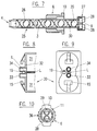
- Fig. 1 shows in a first embodiment a
mixer 1 comprising amixer housing 2, amixer element group 3, amixer outlet 4 and amixer inlet section 5. This mixer is fixed to the cartridge with the aid of acoupling ring 6. It follows in particular from Fig. 2 that themixer inlet section 5 forms two D-shaped,individual inlet openings element 3S serving in this embodiment as a separating means for guiding each component separately to the first dividingelement 3D of themixer element group 3. Aslot 9 aligns the mixer in regard to the cartridge. - As in this case and all further similar mixer embodiments without separated chambers, the
separating element 3S of the mixer element group is arranged such that its leadingedge 20, see Fig. 1, is in line with the plane separating the two inlets and the next element, which is the first dividingelement 3D, is at 90° to it such that its leading edge divides the two component streams evenly for optimum mixing. - At the mixer inlet end facing the cartridge, the
coupling ring 6 see Fig. 5 is provided with twobayonet lugs 10 and, for better manual gripping,ribs 11, on the outer cylindrical surface. - With
cartridge 12, see Figs. 3 and 4, only the outlet area is shown, the cartridge comprising twocylindrical containers 13, a connectingflange 14 with two bayonet prongs 15 receiving thebayonet lugs 10 of the mixer. The two individual, side byside outlets outlet tube 18 comprising anose piece 19 cooperating withslot 9 at the inlet of themixer 1 for aligning themixer 1 to thecartridge 12. The openings of the side byside outlets mixer inlet openings edge 20 of the separatingelement 3S. The cylindricalmixer inlet section 5 is formed for a sealing connection with thecartridge outlet tube 18 while fitting over thenose piece 19 of the cartridge. - It is important to note that when the
mixer 1 is attached to thecartridge 12, both chemical component streams leaving the side byside outlets separating mixer element 3S so that no chemical component material flow is possible from onecartridge outlet 16 across to theother cartridge outlet 17. Leadingedge 20 of the separatingelement 3S ofmixer element group 3, facing thecartridge outlet tube 18, fits and is pressed onto the surface or into thegroove 21 between the two side byside outlets first dividing element 3D of the mixer element group. - When connecting the
mixer 1 to thecartridge 12 thenose piece 19 on the cartridge can only fit intoslot 9 of themixer inlet section 5. This coded connection method assures not only one alignment possibility but also axial mixer attachment without rotation, thus preventing contamination of one chemical component by the other at the side by side outlets. The bayonet lugs 10 of thecoupling ring 6 enable a quick attachment of the mixer. - Figs. 6A-C show a variant to the embodiment shown in Figs. 1-5 in that
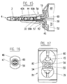
container 70 withoutlet 16A of cartridge 72 has a smaller cross-sectional area thancontainer 71 withoutlet 17A. Also themixer inlet section 22 has a separating means within themixer 73 and comprises separatedinlet chambers 23, resp. 24 having different cross-sectional areas and a smaller combined diameter than the cartridge outlet. This alternative separating means can have separated inlet chambers with equal cross-sectional areas or other than 1:1. For example, the ratio of the cross-sectional areas of the separated inlet chambers can be adapted relative to cross-sectional areas of the containers of the cartridge, resp. to its metering ratio. In this embodiment the separating means is fixedly connected to the mixer element group. - Fig. 7 shows in a
second embodiment mixer 25 comprising amixer housing 26, themixer element group 3, themixer outlet 4 but with amixer inlet section 27 with two cylindrical,separate inlets element 3S ofmixer element group 3. This mixer is also connected to the cartridge with the aid of thecoupling ring 6. Thecoupling ring 6 is the same as or similar to the coupling ring of the previous embodiment, comprising bayonet lugs 10. In this embodiment all mixer internal parts are integral with properly alignedmixer element group 3. - The
cartridge 30 comprises twocylindrical containers 31 of equal cross-sectional area substantially separated by an air gap L, see figs. 8 and 9, anoutlet face 32 with the twobayonet prongs 15 for receiving the bayonet lugs 10 of thecoupling ring 6.Cartridge outlet face 32 comprises two distancedoutlets separate mixer inlets mixer inlet section 27 than reversed arrangements with the same cross-sectional flow area of the cartridge outlets. - By providing a single piece cartridge with complete containers, resp. cylinders which are separated by an air gap L in between, a total chemical separation, substantially along the whole length wherein the chemicals are contained ahead of the cylinder pistons and all the way to the top of the outlets, is both assured and maintained within the mixer inlet section up to the
first dividing element 3D of themixer element group 3. - The invention however, is not limited to air gap separated containers and applies as well to cartridges with containers separated by one single wall according to Fig. 3.
- The
separate inlets separate inlets 36 leading to theseparating element 3S. The method of the aligned connection of the mixer to the cartridge is axial and the same as the aforementioned without rotation of the separating means integral with mixer element group. - Figs. 11A-C show a variant to the embodiment shown in Figs. 7-10 in that the
containers cartridge 78 have different cross-sectional areas and are also separated by an air gap L, see Figs. 11B and 11C. Theinlet section 37 ofmixer 40 is similar to themixer inlet section 27 of Fig. 6, whereby theseparate inlets inlet chamber 38, resp. 39 of different cross-sectional areas so as to correspond to different cartridge metering ratios and are housed in a smaller diameter with reference to themixer inlet section 37 and terminating in an outlet opening for each chamber for material to pass through. This arrangement is preferable for, but not limited to, mixing ratios other than 1:1. Distancedoutlets separate inlets - Fig. 12 shows, in a further embodiment,
mixer 41 comprising amixer housing 42, themixer element group 3, themixer outlet 4 and amixer inlet section 43 with the separatedinlets chambers element 3S of themixer element group 3. This mixer is attached to the cartridge by pressing the mixer onto the cartridge and by rotating themixer housing 42 of the mixer, whereas themixer element group 3 and the separatedchambers longitudinal ribs 44 which end at aflange 45, the two lateral ends of which are formed as bayonet lugs 46 cooperating with the bayonet prongs 15 of the cartridge. The inner wall of themixer inlet section 43 is stepped and the separated chambers are provided with a sealingflange 53. - The
mixer element group 3 is connected to the separatedchambers flange 53 is disposed in such a way within the housing that the housing itself is rotatable around themixer element group 3 with attached separating means and combined separatedinlets flange 53 will provide sealing between the inlet section and the mixer housing containing the mixer element group. - The
cartridge 50 comprises twocylindrical containers 51, and in this embodiment, a connectingflange 52 with the twobayonet prongs 15 for receiving the bayonet lugs 46 of themixer 41. The steppedoutlet nozzle 54 of the cartridge has two individual, separate D-shaped side byside outlets inlets outlets - Figs. 15-17 show a variant to the embodiment shown in Figs. 12-14 in that the
containers cartridge 81 have different cross-sectional areas. Themixer inlet section 57 ofmixer 58 comprises a separatedinlet 59 and aninlet opening 60 but each ending in separatedchambers 59A, resp. 60A with different cross-sections within a reduced diameter in comparison with the inlet section. This arrangement is preferable for mixing ratios other than 1:1, but not limited to them. For mixing ratios other than 1:1 it may be preferable to omitinlet part 49 of the major component which enters the mixer inlet section in order to adapt the cross-section of the flow path to the mixing ratio. - One longitudinal side between the bayonet lugs 46 has a
recess 47, see Fig. 16 and one of the bayonet prongs 15 has, at one of its lateral sides, anose piece 82 for cooperating with thatrecess 47 for the coded alignment of the mixer to the cartridge. - There are other coding means possible at the dispensing apparatus or cartridge and at the accessory for the coded alignment of the accessory to the dispensing apparatus or cartridge, e.g. pins, protruding parts of all kind fitting into a recess or cavity or slot.
- For attaching the mixer to the cartridge, the mixer is aligned and pressed onto the cartridge such that the
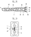
nose 82 fits intorecess 47 of the mixer flange and the inlets of the mixer fit into the outlets of the cartridge. When the mixer is in place and the outlets and inlets are connected,mixer housing 42 of the mixer is rotated by 90° for the engagement of the bayonet lugs 46 in the bayonet prongs of the cartridge. This method prevents the contamination of one chemical component by the other by avoiding relative rotation at the mixer/cartridge interface and enables a quick attachment of the mixer. - The Figs. 18 and 19 show a preferred embodiment, combining the distanced
outlets cartridge 30, having also complete cylindrical containers substantially separated by an air gap L. Amixer 83, with amixer housing 84, has amixer inlet section 85 withseparate inlets element 3S attached to themixer element group 3 ending at themixer outlet 4. Themixer housing 84 is provided withribs 86 ending in bayonet lugs 89 cooperating withbayonet prongs 15 at the cartridge. Correspondingseparate inlets mixer 83 fit over the distancedoutlets cartridge 30. - This mixer is fixed to the cartridge by pressing the mixer onto the cartridge and by rotating the
mixer housing 84 of the mixer, whereas theseparate inlets mixer element group 3, comprising thefirst dividing element 3D, do not rotate. It is evident that this embodiment can also be provided with separated chambers ending at the first dividing element. - All the above described embodiments have the advantage of being compact and result in low moulding and assembly costs since the whole inlet section, comprising the separating means and the mixer element group, is made in one piece. The integral construction of the internal parts ensures proper alignment thus providing optimum mixing efficiency.
- In the situation where a relatively long mixer element group is used and where rotational friction between this group and the housing might cause problems, it may be preferable to separate a part or the whole mixer element group from the separating means of the inlet section such that a part or the whole mixer element group may be fixedly assembled within the housing and therefore rotates while connecting the mixer to the cartridge. In this case - and as seen from the mixer inlet to the mixer outlet - the leading edge of the first element of the mixer element group, or of the portion thereof fixedly assembled within the housing, must be assembled in a pre-aligned position such that after rotating the housing so as to attach the mixer to the cartridge, correct alignment is achieved such that each material stream leaving the separating means, or the first element group attached to the separating means, will be evenly divided by the leading edge of the first element of the element group, or portion thereof fixedly assembled within the housing, for optimizing mixing efficiency.
- It is evident that instead of embodiments with D-shaped inlets and outlets, cylindrical, differently shaped, or dissimilar sized inlets and outlets are possible. Furthermore, the same principle can be used also for a dispensing device or cartridge dispensing more than two components.
- It follows from the above description that the inventive mixer-cartridge combination provides, in particular for cartridge containers substantially separated by an air gap up to and including the individual outlets, a port to port coded alignment for same or dissimilar size ports, with no cross-contamination caused by rotation while also maintaining separation past the interface into the mixer so as to hinder the spreading of any possible reaction and plugging of the components at the interface and back into the cartridge outlets. This combination also provides optimization of the mixing performance, especially but not uniquely, for ratios other than 1:1.
- While the foregoing description and the drawing of the cartridge embodiments pertained to multiple component cartridges with side-by-side containers, the teaching of the present invention is not limited thereto and can be applied as well to cartridges with concentric containers or otherwise arranged and formed containers, having side by side or distanced outlets.
Claims (14)
- A mixer and a multiple reactive component dispensing device assembly, in particular a two-component cartridge, the mixer (1, 25, 40, 41, 58, 73, 83) comprising a mixer housing (2, 26, 42, 42A, 84), a mixer element group (3), a mixer inlet section (5, 22, 27, 37, 43, 57, 85) having separate inlets (7, 8; 28, 29; 48, 49; 56, 60; 87, 88) for each outlet of the cartridge, the cartridge (12, 30, 72, 78, 50, 81) comprising at least two containers (13; 70, 71; 31; 76, 77; 51; 79, 80) and an outlet area with separate outlets (16, 17; 16A, 17A; 33, 34; 55, 56) for each container, the mixer and the cartridge being provided with cooperating attaching means (6, 10; 46, 89; 15), characterized in that the mixer inlet section (5, 22, 27, 37, 43, 57, 85) of the mixer (1, 25, 40, 41, 58, 73, 83) comprises separating means (3S; 23, 24; 38, 39; 48A, 49A; 59A, 60A) for maintaining separation of the components beyond the separate inlets, the mixer element group (3) and the inlet section (5, 22, 27, 37, 43, 57, 85) being arranged such, that while sealingly connecting the mixer to the cartridge, the inlets (7, 8; 28, 29; 48, 49; 59, 60; 87, 88) of the mixer inlet section remain aligned with the corresponding and matching outlets (16, 17; 16A, 17A; 33, 34; 55, 56) of the cartridge and the separating means (3S; 23, 24; 38, 39; 48A, 49A; 59A, 60A) are - after attaching the mixer assembly - aligned with the first dividing element (3D) of the mixer element group (3).
- A mixer according to claim 1, characterized in that the parts of the mixer inlet section (5, 22, 27, 37, 43, 57, 85) including the separating means (3S; 23, 24; 38, 39; 48A, 49A, 59A, 60A) and the mixer element group (3) are aligned and fixedly connected to each other.
- A mixer according to claim 1, characterized in that the mixer element group (3) and the inlet section (43, 57, 85) of the mixer (41, 58, 83) are arranged such that a rotation is possible between the inlet section and the element group, or a portion of the element group , whereby - as seen from the mixer inlet to the mixer outlet - after rotation required to attach the mixer assembly, the leading edge of the first element of the group, or portion thereof which is not fixedly attached to the inlet section, is aligned with the inlet section, or with the element group portion attached to the inlet section, so as to evenly divide each material stream for optimum mixing efficiency.
- A mixer according to any of claims 1 to 3, characterized in that - as seen from the mixer inlet to the mixer outlet - the first element (3S) of the mixer element group (3) is arranged thus that it serves as separating means for maintaining separation of the components.
- A mixer according to any of claims 1 to 3, characterized in that the separating means of the mixer inlet section (22, 37, 43, 57) consists of separated chambers (23, 24; 38, 39; 48A, 49A, 59A, 60A) leading to the first dividing element (3D) of the mixer element group (3).
- A mixer according to any of claims 1, 2, 4, 5, characterized in that the mixer housing (2, 26), the mixer element group (3) and the mixer inlet section (5, 22, 27, 37) are fixedly assembled together and is attached via a coupling ring (6) to the dispensing device or cartridge (12, 30, 72, 78).
- A mixer according to any of claims 1, 2, 4, 5, characterized in that the mixer element group (3) and the mixer inlet section (43, 57, 85) are fixedly connected and arranged in the mixer housing (42, 42A, 84) such that the housing is rotatable around the fixedly connected internal parts of the mixer during the attachment of the mixer to the dispensing device or cartridge.
- A mixer according to claim 3, characterized in that the housing, comprising a fixedly assembled mixer element group (3) or a part of it, is rotatable around the mixer inlet section and separating means, and other part of the element group if applicable, not fixedly assembled to the housing while attaching the mixer to the dispensing device or cartridge.
- A multiple reactive component dispensing device according to claim 1, characterized in that the outlets (33, 34) of the cartridge (30, 78) are separate and individual, arranged side by side or distanced and are approximately D-shaped or cylindrical, or of different cross-section.
- A multiple reactive component dispensing device according to claim 1 or 9, characterized in that the containers (31; 76, 77) and the outlets (33, 34) are substantially separated by an air gap (L) in between.
- An assembly according to any of claims 1 to 10, characterized in that the mixer housing (2, 26, 42A, 84) and the outlet area of the cartridge (12, 72, 30, 78, 81) are provided with mutual coding means (9, 19; 47, 82) for coded alignment of the mixer to the cartridge.
- A multiple reactive component dispensing device, in particular a two-component cartridge according to claim 1, characterized in that the cartridge is a single piece cartridge (30, 78) composed of at least two complete containers (31; 76, 77) with at least two separate outlets (33, 34), substantially separated by an air gap (L) in between.
- A method for connecting the mixer of claim 1 and 6 to a multiple reactive component dispensing device in particular a cartridge, engaging first the inlets of the mixer to the corresponding outlets of the dispensing device and then engaging the attaching means of claim 6 in such a way that the inlets of the mixer remain aligned to the outlets of the cartridge, thus preventing cross-contamination of the components.
- A method for connecting the mixer of claim 1 and 7 or 8 to a multiple reactive component dispensing device, engaging first the inlets of the mixer to the corresponding outlets of the cartridge and then rotating the housing of the mixer for engaging its attaching means to the attaching means of the cartridge in such a way that the inlets of the mixer stay aligned to the outlets of the cartridge, thus preventing cross-contamination of the components.
Priority Applications (3)
| Application Number | Priority Date | Filing Date | Title |
|---|---|---|---|
| EP19950810530 EP0723807B1 (en) | 1995-01-16 | 1995-08-24 | Mixer and multiple component dispensing device assembly and method for the aligned connection of the mixer to the multiple component dispensing device |
| US08/522,108 US5609271A (en) | 1995-01-25 | 1995-08-31 | Mixer and multiple component dispensing device assembly and method for the aligned connection of the mixer to the multiple component dispensing device |
| JP00349296A JP3769058B2 (en) | 1995-01-16 | 1996-01-12 | Assembly and matched coupling method of mixer and multi-reactive component distributor |
Applications Claiming Priority (3)
| Application Number | Priority Date | Filing Date | Title |
|---|---|---|---|
| EP95810027 | 1995-01-16 | ||
| EP95810027 | 1995-01-16 | ||
| EP19950810530 EP0723807B1 (en) | 1995-01-16 | 1995-08-24 | Mixer and multiple component dispensing device assembly and method for the aligned connection of the mixer to the multiple component dispensing device |
Publications (3)
| Publication Number | Publication Date |
|---|---|
| EP0723807A2 true EP0723807A2 (en) | 1996-07-31 |
| EP0723807A3 EP0723807A3 (en) | 1997-02-05 |
| EP0723807B1 EP0723807B1 (en) | 2001-09-19 |
Family
ID=26140654
Family Applications (1)
| Application Number | Title | Priority Date | Filing Date |
|---|---|---|---|
| EP19950810530 Expired - Lifetime EP0723807B1 (en) | 1995-01-16 | 1995-08-24 | Mixer and multiple component dispensing device assembly and method for the aligned connection of the mixer to the multiple component dispensing device |
Country Status (2)
| Country | Link |
|---|---|
| EP (1) | EP0723807B1 (en) |
| JP (1) | JP3769058B2 (en) |
Cited By (15)
| Publication number | Priority date | Publication date | Assignee | Title |
|---|---|---|---|---|
| EP0993864A1 (en) * | 1998-09-18 | 2000-04-19 | Sulzer Chemtech AG | Apparatus and method for mixing and dispensing several fluid components |
| US6161730A (en) * | 1998-09-18 | 2000-12-19 | Sulzer Chemtech Ag | Apparatus for carrying out a mixing dispensing of a plurality of flowable components |
| EP1738737A1 (en) | 2005-07-01 | 2007-01-03 | Kettenbach GmbH & CO. KG | Dimensionally stable articles from cured condensation-crosslinked dental material |
| US7498363B2 (en) | 2004-09-17 | 2009-03-03 | Kettenbach Gmbh & Co. Kg | Two-component dental molding material made of hydroxyl-functional polyethers and alkoxysilanes or silicic acid esters |
| US7504442B2 (en) | 2004-09-17 | 2009-03-17 | Kettenbach Gmbh & Co. Kg | Condensation-crosslinking two-component dental molding material made of alkoxysilyl- and hydroxysilyl-functional polyethers |
| EP2048091A3 (en) * | 2007-10-11 | 2010-01-20 | HILTI Aktiengesellschaft | Cartridge for an extrudable mass |
| DE102009021553A1 (en) | 2009-05-09 | 2010-11-18 | Kettenbach Gmbh & Co. Kg | Curable compositions, cured products made therefrom and their use |
| US7902269B2 (en) | 2004-02-13 | 2011-03-08 | Kettenbach Gmbh & Co. Kg | Dental material based on alkoxysilyl-functional polyethers containing a salt of a strong base as catalyst |
| DE102010046697A1 (en) | 2010-09-28 | 2012-03-29 | Kettenbach Gmbh & Co. Kg | Polymerizable dental material with reactive paste former, cured dental material and their use |
| WO2012172078A1 (en) * | 2011-06-16 | 2012-12-20 | Vosschemie Gmbh | Static mixer for mixing at least two flowable components |
| EP2599540A1 (en) | 2011-11-29 | 2013-06-05 | Sulzer Mixpac AG | Mixing element for a static mixer |
| WO2014033280A2 (en) | 2012-08-31 | 2014-03-06 | Kettenbach Gmbh & Co. Kg | Radically polymerisable dental material, cured product and usage |
| EP2965825A1 (en) * | 2014-07-09 | 2016-01-13 | Sulzer Mixpac AG | Dispensing apparatus, dispensing system and method of dispensing |
| US9381070B2 (en) | 2013-03-01 | 2016-07-05 | Gc Corporation | Dental mixer |
| EP3162433A1 (en) * | 2015-10-30 | 2017-05-03 | Sulzer Mixpac AG | Static mixer |
Families Citing this family (7)
| Publication number | Priority date | Publication date | Assignee | Title |
|---|---|---|---|---|
| DE102006001126A1 (en) | 2006-01-09 | 2007-07-12 | Kettenbach Gmbh & Co. Kg | Dental impression compounds, hardened products prepared therefrom and use of surfactants for the production of dental impression compounds |
| JP5172185B2 (en) | 2007-03-22 | 2013-03-27 | 株式会社ジーシー | Mixing chip |
| DE102007044983B4 (en) | 2007-09-19 | 2014-03-20 | Kettenbach Gmbh & Co. Kg | discharge |
| WO2009036962A2 (en) | 2007-09-19 | 2009-03-26 | Kettenbach Gmbh & Co. Kg | Dispensing device |
| JP5172514B2 (en) | 2008-07-15 | 2013-03-27 | 株式会社ジーシー | Mixing chip |
| WO2013026717A1 (en) | 2011-08-24 | 2013-02-28 | Kettenbach Gmbh & Co. Kg | Cartridge system and static mixer therefor |
| DE102012003390B4 (en) | 2011-08-24 | 2018-04-26 | Kettenbach Gmbh & Co. Kg | Cartridge system and static mixer for this |
Citations (5)
| Publication number | Priority date | Publication date | Assignee | Title |
|---|---|---|---|---|
| US4538920A (en) | 1983-03-03 | 1985-09-03 | Minnesota Mining And Manufacturing Company | Static mixing device |
| US4767026A (en) | 1987-01-16 | 1988-08-30 | Keller Wilhelm A | Dispensing and mixing apparatus |
| US5228599A (en) | 1990-07-20 | 1993-07-20 | Keller Wilhelm A | Multiple dispensing cartridge for multiple-component substances |
| DE9405922U1 (en) | 1994-04-09 | 1994-06-30 | Prestele Eugen | Two-component cartridge |
| US5333760A (en) | 1992-12-28 | 1994-08-02 | Coltene/Whaledent, Inc. | Dispensing and mixing apparatus |
Family Cites Families (8)
| Publication number | Priority date | Publication date | Assignee | Title |
|---|---|---|---|---|
| US3767085A (en) * | 1971-08-02 | 1973-10-23 | J Cannon | Mixing syringe |
| JPS60150820A (en) * | 1984-01-13 | 1985-08-08 | Colpo Co Ltd | Liquid pouring tool capable of stirring and mixing |
| EP0261466B1 (en) * | 1986-09-14 | 1990-07-25 | Wilhelm A. Keller | Double discharge cartridge for two-component compounds |
| DE3873628D1 (en) * | 1987-06-10 | 1992-09-17 | Wilhelm A Keller | DOUBLE DISCHARGE CARTRIDGE FOR TWO-COMPONENT DIMENSIONS. |
| DE8900469U1 (en) * | 1989-01-17 | 1990-05-23 | Espe Stiftung & Co Produktions- Und Vertriebs Kg, 8031 Seefeld, De | |
| DE9015118U1 (en) * | 1990-11-02 | 1992-02-27 | Muehlbauer, Ernst, 2000 Hamburg, De | |
| DE4138351A1 (en) * | 1991-11-21 | 1993-05-27 | Bostik Gmbh | Two-component paste premixer - has structured inner walls to lay adjacent material strands in alternating layers and hence achieves a homogeneous mixt. with low delivery pressure |
| DE59205705D1 (en) * | 1992-08-24 | 1996-04-18 | Wilhelm A Keller | Mixer for double discharge cartridges |
-
1995
- 1995-08-24 EP EP19950810530 patent/EP0723807B1/en not_active Expired - Lifetime
-
1996
- 1996-01-12 JP JP00349296A patent/JP3769058B2/en not_active Expired - Lifetime
Patent Citations (5)
| Publication number | Priority date | Publication date | Assignee | Title |
|---|---|---|---|---|
| US4538920A (en) | 1983-03-03 | 1985-09-03 | Minnesota Mining And Manufacturing Company | Static mixing device |
| US4767026A (en) | 1987-01-16 | 1988-08-30 | Keller Wilhelm A | Dispensing and mixing apparatus |
| US5228599A (en) | 1990-07-20 | 1993-07-20 | Keller Wilhelm A | Multiple dispensing cartridge for multiple-component substances |
| US5333760A (en) | 1992-12-28 | 1994-08-02 | Coltene/Whaledent, Inc. | Dispensing and mixing apparatus |
| DE9405922U1 (en) | 1994-04-09 | 1994-06-30 | Prestele Eugen | Two-component cartridge |
Cited By (29)
| Publication number | Priority date | Publication date | Assignee | Title |
|---|---|---|---|---|
| EP0993864A1 (en) * | 1998-09-18 | 2000-04-19 | Sulzer Chemtech AG | Apparatus and method for mixing and dispensing several fluid components |
| US6161730A (en) * | 1998-09-18 | 2000-12-19 | Sulzer Chemtech Ag | Apparatus for carrying out a mixing dispensing of a plurality of flowable components |
| US7902269B2 (en) | 2004-02-13 | 2011-03-08 | Kettenbach Gmbh & Co. Kg | Dental material based on alkoxysilyl-functional polyethers containing a salt of a strong base as catalyst |
| US7498363B2 (en) | 2004-09-17 | 2009-03-03 | Kettenbach Gmbh & Co. Kg | Two-component dental molding material made of hydroxyl-functional polyethers and alkoxysilanes or silicic acid esters |
| US7504442B2 (en) | 2004-09-17 | 2009-03-17 | Kettenbach Gmbh & Co. Kg | Condensation-crosslinking two-component dental molding material made of alkoxysilyl- and hydroxysilyl-functional polyethers |
| US7790781B2 (en) | 2005-07-01 | 2010-09-07 | Kettenbach Gmbh & Co. Kg | Condensation-crosslinkable dental material hardening to dimensionally stable casts |
| EP1738737A1 (en) | 2005-07-01 | 2007-01-03 | Kettenbach GmbH & CO. KG | Dimensionally stable articles from cured condensation-crosslinked dental material |
| EP2048091A3 (en) * | 2007-10-11 | 2010-01-20 | HILTI Aktiengesellschaft | Cartridge for an extrudable mass |
| AU2008227079B2 (en) * | 2007-10-11 | 2010-09-16 | Hilti Ag | Cartridge for an ejectable compound |
| US8042926B2 (en) | 2007-10-11 | 2011-10-25 | Hilti Aktiengesellschaft | Cartridge for an ejectable compound |
| DE102009021553A1 (en) | 2009-05-09 | 2010-11-18 | Kettenbach Gmbh & Co. Kg | Curable compositions, cured products made therefrom and their use |
| EP2253302A2 (en) | 2009-05-09 | 2010-11-24 | Kettenbach GmbH & CO. KG | Hardening compounds, products derived from same and use thereof |
| DE202009018142U1 (en) | 2009-05-09 | 2011-02-24 | Kettenbach Gmbh & Co. Kg | Curable compositions, cured products made therefrom and their use |
| US8614262B2 (en) | 2009-05-09 | 2013-12-24 | Kettenbach Gmbh & Co. Kg | Curable compositions, cured products produced therefrom and use thereof |
| WO2012052249A2 (en) | 2010-09-28 | 2012-04-26 | Kettenbach Gmbh & Co. Kg | Polymerizable dental material comprising reactive paste formers, hardened dental material and use thereof |
| DE102010046697A1 (en) | 2010-09-28 | 2012-03-29 | Kettenbach Gmbh & Co. Kg | Polymerizable dental material with reactive paste former, cured dental material and their use |
| WO2012172078A1 (en) * | 2011-06-16 | 2012-12-20 | Vosschemie Gmbh | Static mixer for mixing at least two flowable components |
| EP2599540A1 (en) | 2011-11-29 | 2013-06-05 | Sulzer Mixpac AG | Mixing element for a static mixer |
| US10293311B2 (en) | 2011-11-29 | 2019-05-21 | Sulzer Mixpac Ag | Mixing element for a static mixer |
| WO2014033280A2 (en) | 2012-08-31 | 2014-03-06 | Kettenbach Gmbh & Co. Kg | Radically polymerisable dental material, cured product and usage |
| US9381070B2 (en) | 2013-03-01 | 2016-07-05 | Gc Corporation | Dental mixer |
| WO2016005383A1 (en) * | 2014-07-09 | 2016-01-14 | Sulzer Mixpac Ag | Dispensing apparatus, dispensing system and method of dispensing |
| EP2965825A1 (en) * | 2014-07-09 | 2016-01-13 | Sulzer Mixpac AG | Dispensing apparatus, dispensing system and method of dispensing |
| US10300506B2 (en) | 2014-07-09 | 2019-05-28 | Sulzer Mixpac Ag | Dispensing apparatus, dispensing system and method of dispensing |
| EP3162433A1 (en) * | 2015-10-30 | 2017-05-03 | Sulzer Mixpac AG | Static mixer |
| WO2017072079A1 (en) * | 2015-10-30 | 2017-05-04 | Sulzer Mixpac Ag | Static mixer |
| CN106943909A (en) * | 2015-10-30 | 2017-07-14 | 苏舍米克斯帕克有限公司 | Static mixer |
| US10786790B2 (en) | 2015-10-30 | 2020-09-29 | Sulzer Mixpac Ag | Multicomponent static mixer for mixing components |
| CN106943909B (en) * | 2015-10-30 | 2021-06-29 | 苏舍米克斯帕克有限公司 | Static mixer |
Also Published As
| Publication number | Publication date |
|---|---|
| EP0723807B1 (en) | 2001-09-19 |
| JP3769058B2 (en) | 2006-04-19 |
| JPH08276125A (en) | 1996-10-22 |
| EP0723807A3 (en) | 1997-02-05 |
Similar Documents
| Publication | Publication Date | Title |
|---|---|---|
| US5609271A (en) | Mixer and multiple component dispensing device assembly and method for the aligned connection of the mixer to the multiple component dispensing device | |
| EP0723807B1 (en) | Mixer and multiple component dispensing device assembly and method for the aligned connection of the mixer to the multiple component dispensing device | |
| JP3655003B2 (en) | Plug-in locking device for correctly attaching accessories to multi-component cartridges or dispensing devices | |
| US6186363B1 (en) | Bayonet fastening device for the attachment of an accessory to a multiple component cartridge or dispensing device | |
| US6769574B1 (en) | Dispensing assembly having coded attachment of an accessory to a multiple component cartridge or dispensing device using differently sized inlets and outlets | |
| US4767026A (en) | Dispensing and mixing apparatus | |
| CA2311815C (en) | Double-barreled syringe with detachable locking mixing tip | |
| EP1656215B2 (en) | Unit-dose syringe for a multi-component material | |
| KR101435928B1 (en) | A multicomponent cartridge | |
| US6161730A (en) | Apparatus for carrying out a mixing dispensing of a plurality of flowable components | |
| JP5030950B2 (en) | Multi-component distributor with valve assembly | |
| US6398761B1 (en) | Double syringe barrels with ported delivery ends | |
| USRE36235E (en) | Dispensing and mixing apparatus | |
| JPH05246460A (en) | Container for flowable substances | |
| GB2304101A (en) | Dual cartridge dispenser and closure therefor | |
| CA2362946A1 (en) | Mixing adaptor and system | |
| JPH0866627A (en) | Mixer for compound distribution cartridge | |
| US8899446B2 (en) | Apparatus for mixing and dispensing multiple flowable components | |
| US8499976B2 (en) | Multichamber dispensing device | |
| EP4252897A1 (en) | Mixer for mixing at least two materials and mixing and dispensing assembly | |
| EP4252896A1 (en) | Mixer for mixing and dispensing at least two components | |
| EP4252899A1 (en) | Mixer assembly for mixing at least two materials | |
| CA1277641C (en) | Dispensing and mixing apparatus |
Legal Events
| Date | Code | Title | Description |
|---|---|---|---|
| PUAI | Public reference made under article 153(3) epc to a published international application that has entered the european phase |
Free format text: ORIGINAL CODE: 0009012 |
|
| AK | Designated contracting states |
Kind code of ref document: A2 Designated state(s): CH DE FR GB IT LI |
|
| AX | Request for extension of the european patent |
Free format text: LT;LV;SI |
|
| RAX | Requested extension states of the european patent have changed |
Free format text: LT;LV;SI |
|
| RBV | Designated contracting states (corrected) |
Designated state(s): CH DE FR GB IT LI |
|
| PUAL | Search report despatched |
Free format text: ORIGINAL CODE: 0009013 |
|
| 17P | Request for examination filed |
Effective date: 19961113 |
|
| AK | Designated contracting states |
Kind code of ref document: A3 Designated state(s): CH DE FR GB IT LI |
|
| AX | Request for extension of the european patent |
Free format text: LT;LV;SI |
|
| 17Q | First examination report despatched |
Effective date: 19980703 |
|
| TPAD | Observations filed by third parties |
Free format text: ORIGINAL CODE: EPIDOS TIPA |
|
| GRAG | Despatch of communication of intention to grant |
Free format text: ORIGINAL CODE: EPIDOS AGRA |
|
| GRAG | Despatch of communication of intention to grant |
Free format text: ORIGINAL CODE: EPIDOS AGRA |
|
| GRAH | Despatch of communication of intention to grant a patent |
Free format text: ORIGINAL CODE: EPIDOS IGRA |
|
| GRAH | Despatch of communication of intention to grant a patent |
Free format text: ORIGINAL CODE: EPIDOS IGRA |
|
| DAX | Request for extension of the european patent (deleted) | ||
| GRAA | (expected) grant |
Free format text: ORIGINAL CODE: 0009210 |
|
| AK | Designated contracting states |
Kind code of ref document: B1 Designated state(s): CH DE FR GB IT LI |
|
| ITF | It: translation for a ep patent filed |
Owner name: BARZANO' E ZANARDO MILANO S.P.A. |
|
| REG | Reference to a national code |
Ref country code: CH Ref legal event code: NV Representative=s name: AMMANN PATENTANWAELTE AG BERN Ref country code: CH Ref legal event code: EP |
|
| REF | Corresponds to: |
Ref document number: 69522793 Country of ref document: DE Date of ref document: 20011025 |
|
| REG | Reference to a national code |
Ref country code: GB Ref legal event code: IF02 |
|
| ET | Fr: translation filed | ||
| PLBE | No opposition filed within time limit |
Free format text: ORIGINAL CODE: 0009261 |
|
| STAA | Information on the status of an ep patent application or granted ep patent |
Free format text: STATUS: NO OPPOSITION FILED WITHIN TIME LIMIT |
|
| 26N | No opposition filed | ||
| REG | Reference to a national code |
Ref country code: GB Ref legal event code: 732E |
|
| REG | Reference to a national code |
Ref country code: FR Ref legal event code: TP |
|
| REG | Reference to a national code |
Ref country code: CH Ref legal event code: PUE Owner name: MIXPAC SYSTEMS AG Free format text: KELLER, WILHELM A.#OBSTGARTENWEG 9#CH-6402 MERLISCHACHEN (CH) -TRANSFER TO- MIXPAC SYSTEMS AG#GRUNDSTRASSE 12#6343 ROTKREUZ (CH) |
|
| REG | Reference to a national code |
Ref country code: DE Ref legal event code: R082 Ref document number: 69522793 Country of ref document: DE Representative=s name: MANITZ, FINSTERWALD & PARTNER GBR, DE |
|
| REG | Reference to a national code |
Ref country code: DE Ref legal event code: R082 Ref document number: 69522793 Country of ref document: DE Representative=s name: MANITZ FINSTERWALD PATENTANWAELTE PARTMBB, DE Effective date: 20111205 Ref country code: DE Ref legal event code: R082 Ref document number: 69522793 Country of ref document: DE Representative=s name: MANITZ, FINSTERWALD & PARTNER GBR, DE Effective date: 20111205 Ref country code: DE Ref legal event code: R081 Ref document number: 69522793 Country of ref document: DE Owner name: SULZER MIXPAC AG, CH Free format text: FORMER OWNER: MIXPAC SYSTEMS AG, ROTKREUZ, CH Effective date: 20111205 |
|
| REG | Reference to a national code |
Ref country code: DE Ref legal event code: R008 Ref document number: 69522793 Country of ref document: DE |
|
| REG | Reference to a national code |
Ref country code: DE Ref legal event code: R039 Ref document number: 69522793 Country of ref document: DE Effective date: 20121207 |
|
| REG | Reference to a national code |
Ref country code: CH Ref legal event code: PFUS Owner name: SULZER MIXPAC AG, CH Free format text: FORMER OWNER: MIXPAC SYSTEMS AG, CH Ref country code: CH Ref legal event code: NV Representative=s name: DR. GRAF AND PARTNER AG INTELLECTUAL PROPERTY, CH |
|
| REG | Reference to a national code |
Ref country code: GB Ref legal event code: 732E Free format text: REGISTERED BETWEEN 20140410 AND 20140416 |
|
| REG | Reference to a national code |
Ref country code: DE Ref legal event code: R097 Ref document number: 69522793 Country of ref document: DE Ref country code: DE Ref legal event code: R040 Ref document number: 69522793 Country of ref document: DE |
|
| REG | Reference to a national code |
Ref country code: DE Ref legal event code: R040 Ref document number: 69522793 Country of ref document: DE Effective date: 20140616 |
|
| PGFP | Annual fee paid to national office [announced via postgrant information from national office to epo] |
Ref country code: DE Payment date: 20140821 Year of fee payment: 20 Ref country code: CH Payment date: 20140820 Year of fee payment: 20 |
|
| PGFP | Annual fee paid to national office [announced via postgrant information from national office to epo] |
Ref country code: GB Payment date: 20140820 Year of fee payment: 20 Ref country code: FR Payment date: 20140821 Year of fee payment: 20 |
|
| PGFP | Annual fee paid to national office [announced via postgrant information from national office to epo] |
Ref country code: IT Payment date: 20140828 Year of fee payment: 20 |
|
| REG | Reference to a national code |
Ref country code: DE Ref legal event code: R071 Ref document number: 69522793 Country of ref document: DE |
|
| REG | Reference to a national code |
Ref country code: CH Ref legal event code: PL |
|
| REG | Reference to a national code |
Ref country code: GB Ref legal event code: PE20 Expiry date: 20150823 |
|
| PG25 | Lapsed in a contracting state [announced via postgrant information from national office to epo] |
Ref country code: GB Free format text: LAPSE BECAUSE OF EXPIRATION OF PROTECTION Effective date: 20150823 |